Embed Size (px)
Citation preview

Installazione Uso e Manutenzione
Installation, Operation and Maintenance Instructions
POSIZIONATORI PER SERVOMOTORI ROTANTI
ROTARY VALVE POSITIONERS
R99P R99E
PVP11BE.1 ATEX
Our products are manufactured under ISO-9001 Quality Assurance System, approved by CSQ certified under nr.9190.OMC2 - FIRST ISSUE 1994/08/04
OMC s.r.l. Industrial Automation Equipment
Valve positioners Posizionatori per valvole
ManR99ne 04/2014
Pag.2
In caso di problemi di installazione o di funzionamento,contattare il nostro Agente locale o il Servizio di AssistenzaTecnica OMC s.r.l.
In case of problems with the installation or operation of thisequipment please contact our Local Agent or our ServiceDepartment.
INDICE
1. DESCRIZIONE
2. DATI TECNICI
3. INSTALLAZIONE
2.1 MATERIALI
2.2 PORTATA ARIA
2.3 CONSUMO D'ARIA
2.4 DIMENSIONI DI INGOMBRO
3.1 MONTAGGIO SULL'ATTUATORE
INDEX
1. DESCRIPTION
2. TECHNICAL DATA
3. INSTALLATION
2.1 MATERIALS
2.2 AIR DELIVERY
2.3 AIR CONSUMPTION
2.4 DIMENSIONS
3.1 FITTING TO THE ACTUATOR
4. COORDINAMENTO TRA ATTUATUATORE E POSIZIONATORE
4. CORDINATION BETWEEN POSITIONER AND ACTUATOR
4.1 ATTUATORI A DOPPIO EFFETTO 4.1 DOUBLE ACTING ACUATORS
4.2 ATTUATORI A SEMPLICE EFFETTO 4.2 SINGLE ACTING ACTUATORS
5. CONNESSIONI ELETTRICHE E PNEUMATICHE 5. AIR AND ELECTRICAL CONNECTIONS
6. MONTAGGIO ACCESSORI 6. ACCESSORIES
7. MESSA IN FUNZIONE 7. COMMISSIONING
8. FUNZIONAMENTO IN SPLIT RANGE 8. SPLIT RANGE OPERATION
10. INVERSIONE DEL SENSO DI ROTAZIONE
10. REVERSING OF ROTATION
9. REGOLAZIONE VELOCITÀ VALVOLA
9.VALVE SPEED ADJUSTMENT
11. RICAMBI 11. SPARE PARTS
11.1 R99E e PVP11BE.1 11.1 R99E & PVP11BE.1
11.2 R99P 11.2 R99P
13. MALFUNZIONAMENTO: SINTOMI, CAUSE E RIMEDI
13. TROUBLE CHART: SYMPTOMS, CAUSES AND ACTION TO TAKE
12. MANUTENZIONE 12. MAINTENANCE
OMC s.r.l. - Via Galileo Galilei, 18 - 20060 Cassina de Pecchi (MI) - ITALY
Tel.: (+39) 02.95.28.468 - Fax: (+39) 02.95.21.495 - [email protected]
Pag. 3
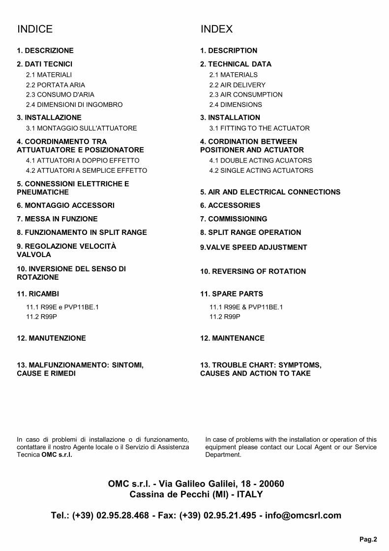
Posizionatore a semplice e doppio effetto con segnalein entrata 4÷20mA (R99E) o 3÷15 psi (R99P) perl'azionamento proporzionale di cilindri rotanti.L'apparecchio opera secondo il principio di equilibriodelle forze. Confronta il segnale standard di unregolatore elettronico o pneumatico con l'angolo dirotazione dello stelo inviando un segnale amplificatoche agisce sulle camere dell'attuatore. Disponibilianche nella versione a sicurezza intrinseca (Ex ia IICT6, T5 - ATEX - 94/9/CE- : II 1 G) mod. PVP11BE.1.
Single & double-acting Positioner, input signal4÷20mA (R99E) or 0.2÷1bar (R99P) for proportionalcontrol of rotary actuators. The positioner operates onthe force-balance principle by comparing the standardsignal transmitted from a pneumatic or an electroniccontroller device and the angular rotation of the stem,and conveys a positioning amplified pressure to thevalve actuator. An intrinsically safe version (Ex ia IICT6, T5 - ATEX - 94/9/CE- : II 1 G), PVP11BE.1 is alsoavailable.
1. DESCRIZIONE 1. DESCRIPTION
2. DATI TECNICI 2. TECHNICAL DATA
MONTAGGIO
CAMMA (Azione diretta o inversa)
CONNESSIONI PNEUMATICHE
ARIA DI ALIMENTAZIONE
USCITA
RIPETIBILITA'R99P
R99E - PVP11BE.1
ISTERESIR99P
R99E - PVP11BE.1
LINEARITA'R99P
R99E - PVP11BE.1
GRADO DI PROTEZIONEEN 60529
PESO CON MANOMETRI
TEMPERATURA AMBIENTE
R99P
R99E - PVP11BE.1
TEMPERATURA DI STOCCAGGIO
SEGNALE DI COMANDO
R99P
R99E - PVP11BE.1
CONNESSIONI ELETTRICHE(R99E e PVP11BE.1)
Ui
Ii
Pi
Impedenza
Ci
Li
MOUNTINGSu staffa ISO
CAM (Direct and reverse action)
0÷20° (*)0÷60° (standard) 0÷90° (standard)
0÷180° (*)0÷270° (*)0÷360° (*)
altre camme (*)
PNEUMATIC CONNECTIONS1/4" NPT
SUPPLY AIR PRESSURE3…10 bar
OUTPUT0...100 % della pressione di
alimentazione
REPEATIBILITY< 0,1 % del campo
< 0,2 % del campo
R99P
R99E - PVP11BE.1
< 0,6 % del campo
< 1 % del campoHYSTERESIS
R99P
R99E - PVP11BE.1
NON LINEARITY< 1,7 % del campo
< 2 % del campo
R99P
R99E - PVP11BE.1
PROTECTION CLASS(acc. to EN 60529)
IP55
WEIGHT WITH GAUGES2,4 Kg
AMBIENT TEMPERTURE
-20....+80 °C
-20....+70 °C
R99P
R99E - PVP11BE.1
STORAGE TEMPERATURE-30....+80 °C
INPUT
3÷15 Psi (0,2÷1 bar)altri segnali (*)
4 ÷ 20 mAaltri segnali (*)
R99P
R99E - PVP11BE.1
ELECTRIC CONNECTIONS(R99E and PVP11BE.1)
Pressacavo PG9altre misure (*)
Ui 30 V
Ii 150 mA
Pi 0,80 W
ImpedanceMax 250
Ci 0 (trascurabile)
Li 0 (trascurabile)
ISO reccomendedmounting bracket
0÷20° (*)0÷60° (standard) 0÷90° (standard)
0÷180° (*)0÷270° (*)0÷360° (*)
other cam (*)
1/4" NPT
3…10 bar
0...100 % of the supply air pressure
< 0,1 % of full range
< 0.2 % of full range
< 0,6 % of full range
< 1 % of full range
< 1,7 % of full range
< 2 % of full range
IP55
2,4 Kg
-20....+80 °C
-20....+70 °C
-30....+80 °C
3÷15 Psi (0,2÷1 bar)other input (*)
4 ÷ 20 mAother input(*)
Cable gland PG9other connections (*)
30 V
150 mA
0,80 W
Max 250
0 (negligible)
0 (negligible)
(*) su richiesta (*) on request
Pag. 4
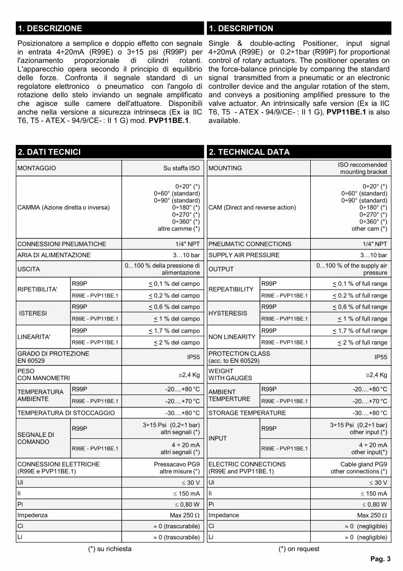
2.1 MATERIALI 2.1 MATERIALS
OU
TP
UT
SU
PP
LY
OU
TP
UT
SE
GN
ALE
DI C
OM
AN
DO
3 ÷
15 P
SI
3 ÷
15 P
SI
INP
UT
SIG
NA
L
ALIMENTAZIONE 4 BAR
2.2 PORTATA ARIA 2.2 AIR DELIVERY
regolabile da 1 a 16 Nm³/h 4 BAR SUPPLY adjustable from 1 to 16 Nm³/hProva effettuata con tubo 6 x 8 mm Test effected with pipe 6 x 8 mm
ALIMENTAZIONE 6 BAR regolabile da 1 a 22 Nm³/h 6 BAR SUPPLY adjustable from 1 to 22 Nm³/hALIMENTAZIONE 8 BAR regolabile da 1 a 28 Nm³/h 8 BAR SUPPLY adjustable from 1 to 28 Nm³/hALIMENTAZIONE 10 BAR regolabile da 1 a 34 Nm³/h 10 BAR SUPPLY adjustable from 1 to 34 Nm³/h
ALIMENTAZIONE 4 BAR
2.3 CONSUMO D'ARIA 2.3 AIR CONSUMPTION
max 0,4 Nm³/h 4 BAR SUPPLY max 0,4 Nm³/hProva effettuata con tubo 6 x 8 mm Test effected with pipe 6 x 8 mm
ALIMENTAZIONE 6 BAR max 0,8 Nm³/h 6 BAR SUPPLY max 0,8 Nm³/hALIMENTAZIONE 8 BAR max 1,0 Nm³/h 8 BAR SUPPLY max 1,0 Nm³/hALIMENTAZIONE 10 BAR max 1,5 Nm³/h 10 BAR SUPPLY max 1,5 Nm³/h
2.4 DIMENSIONI DI INGOMBRO 2.4 DIMENSIONS
Fig. 2.4
156
117
88
134
134
135
PolicarbonatoRP01 / RE01 PolycarbonateR99P / R99E
COPERCHIO COVERIn alluminio pressofuso verniciatura antiacido
PVP11BE.1Die cast aluminium with
anti corrosive paint PVP11BE.1
CORPO
INDICATORE DI POSIZIONE
BODY
POSITION INDICATOR
In alluminio pressofuso verniciatura antiacido
Policarbonato
Die cast aluminium with anti corrosive paint
Polycarbonate
LEVE LEVERSLega di zinco (ZAMA) Zamak
CAMMA CAMAcciaio INOX Stainless Steel
CASSETTO DISTRIBUTORE SLIDE VALVECassetto: Lega di BronzoPerno: Acciaio INOX
Box: Copper AlloyPivot: Stainless Steel
MEMBRANA RICEVITORE RECEIVER DIAPHRAGMGomma nitrilica Nitrile Rubber
Pag. 5
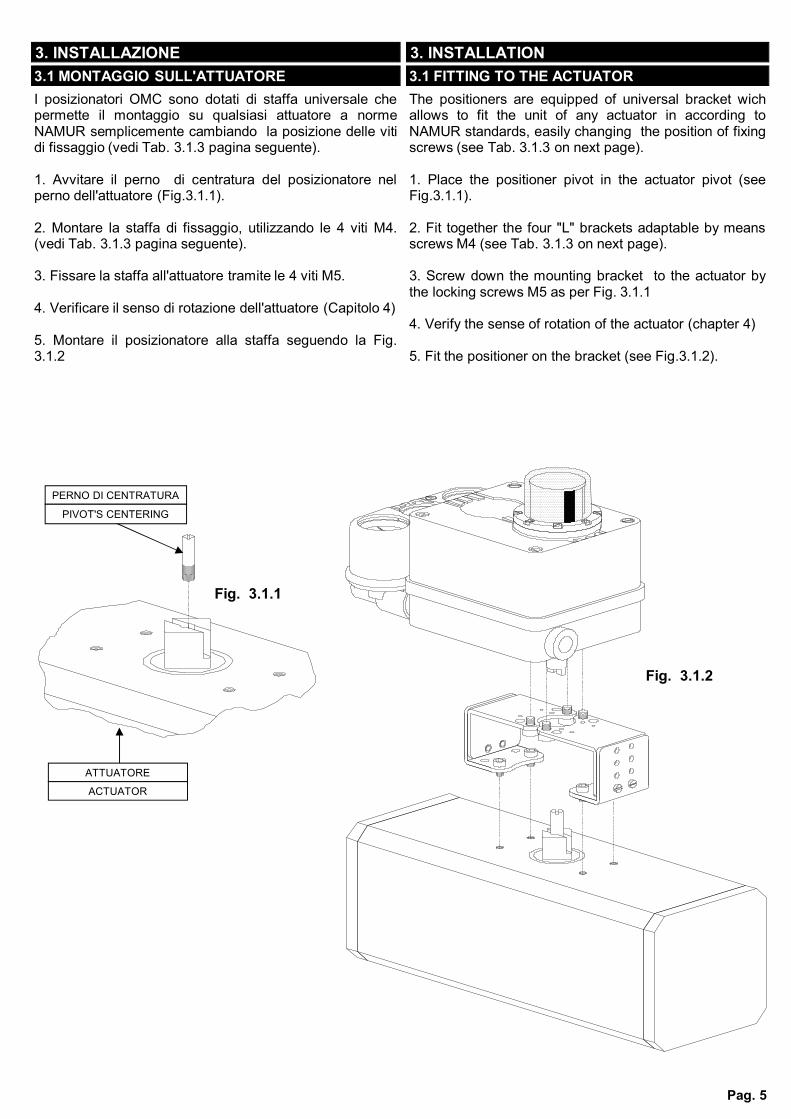
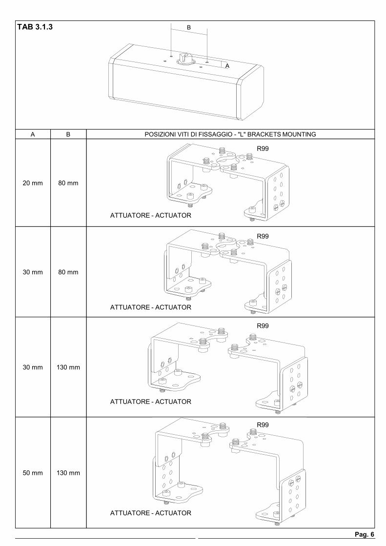
I posizionatori OMC sono dotati di staffa universale chepermette il montaggio su qualsiasi attuatore a normeNAMUR semplicemente cambiando la posizione delle vitidi fissaggio (vedi Tab. 3.1.3 pagina seguente).
1. Avvitare il perno di centratura del posizionatore nelperno dell'attuatore (Fig.3.1.1).
2. Montare la staffa di fissaggio, utilizzando le 4 viti M4.(vedi Tab. 3.1.3 pagina seguente).
3. Fissare la staffa all'attuatore tramite le 4 viti M5.
4. Verificare il senso di rotazione dell'attuatore (Capitolo 4)
5. Montare il posizionatore alla staffa seguendo la Fig.3.1.2
The positioners are equipped of universal bracket wichallows to fit the unit of any actuator in according toNAMUR standards, easily changing the position of fixingscrews (see Tab. 3.1.3 on next page).
1. Place the positioner pivot in the actuator pivot (seeFig.3.1.1).
2. Fit together the four "L" brackets adaptable by meansscrews M4 (see Tab. 3.1.3 on next page).
3. Screw down the mounting bracket to the actuator bythe locking screws M5 as per Fig. 3.1.1
4. Verify the sense of rotation of the actuator (chapter 4)
5. Fit the positioner on the bracket (see Fig.3.1.2).
Fig. 3.1.1
PERNO DI CENTRATURA
ATTUATORE
ACTUATOR
PIVOT'S CENTERING
Fig. 3.1.2
3. INSTALLAZIONE 3. INSTALLATION
3.1 MONTAGGIO SULL'ATTUATORE 3.1 FITTING TO THE ACTUATOR
Pag. 6
A
B
POSIZIONI VITI DI FISSAGGIO - "L" BRACKETS MOUNTINGBA
80 mm20 mm
80 mm30 mm
130 mm30 mm
130 mm50 mm
TAB 3.1.3
R99
R99
R99
R99
ATTUATORE - ACTUATOR
ATTUATORE - ACTUATOR
ATTUATORE - ACTUATOR
ATTUATORE - ACTUATOR
Pag. 7
OUT 2
P 1OUT 1
P 2
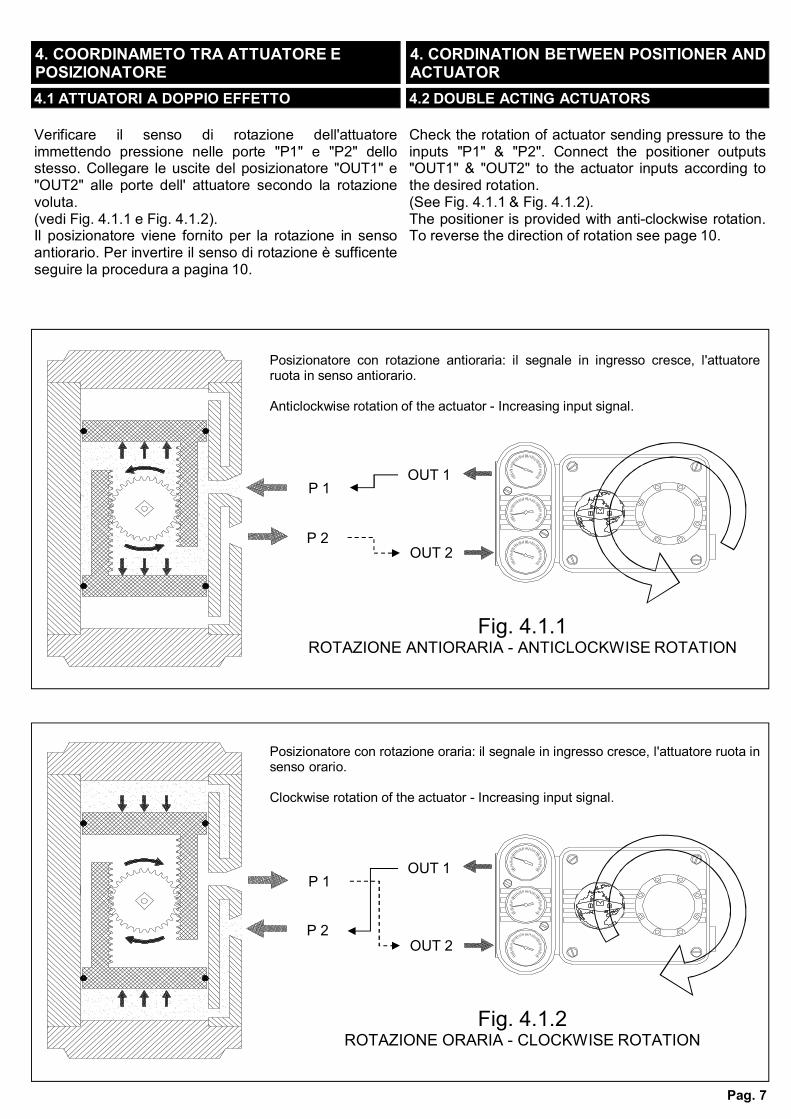
Posizionatore con rotazione antioraria: il segnale in ingresso cresce, l'attuatoreruota in senso antiorario.
Anticlockwise rotation of the actuator - Increasing input signal.
Fig. 4.1.1ROTAZIONE ANTIORARIA - ANTICLOCKWISE ROTATION
OUT 2
P 1OUT 1
P 2
Posizionatore con rotazione oraria: il segnale in ingresso cresce, l'attuatore ruota insenso orario.
Clockwise rotation of the actuator - Increasing input signal.
Fig. 4.1.2ROTAZIONE ORARIA - CLOCKWISE ROTATION
Verificare il senso di rotazione dell'attuatoreimmettendo pressione nelle porte "P1" e "P2" dellostesso. Collegare le uscite del posizionatore "OUT1" e"OUT2" alle porte dell' attuatore secondo la rotazionevoluta.(vedi Fig. 4.1.1 e Fig. 4.1.2).Il posizionatore viene fornito per la rotazione in sensoantiorario. Per invertire il senso di rotazione è sufficenteseguire la procedura a pagina 10.
Check the rotation of actuator sending pressure to theinputs "P1" & "P2". Connect the positioner outputs"OUT1" & "OUT2" to the actuator inputs according tothe desired rotation.(See Fig. 4.1.1 & Fig. 4.1.2).The positioner is provided with anti-clockwise rotation.To reverse the direction of rotation see page 10.
4. COORDINAMETO TRA ATTUATORE E POSIZIONATORE
4. CORDINATION BETWEEN POSITIONER AND ACTUATOR
4.1 ATTUATORI A DOPPIO EFFETTO 4.2 DOUBLE ACTING ACTUATORS
Pag. 8
OUT 2
P 1OUT 1
P 2
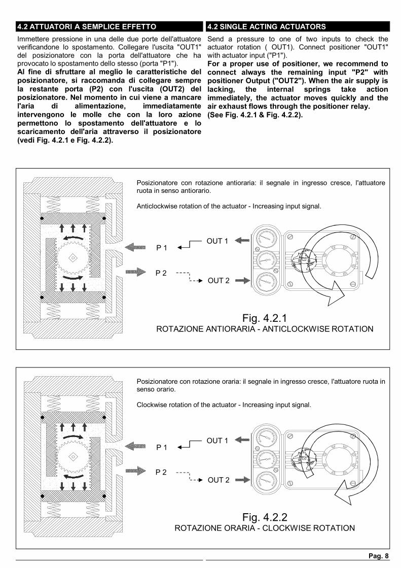
Posizionatore con rotazione antioraria: il segnale in ingresso cresce, l'attuatoreruota in senso antiorario.
Anticlockwise rotation of the actuator - Increasing input signal.
Fig. 4.2.1ROTAZIONE ANTIORARIA - ANTICLOCKWISE ROTATION
OUT 2
P 1OUT 1
P 2
Posizionatore con rotazione oraria: il segnale in ingresso cresce, l'attuatore ruota insenso orario.
Clockwise rotation of the actuator - Increasing input signal.
Fig. 4.2.2ROTAZIONE ORARIA - CLOCKWISE ROTATION
Immettere pressione in una delle due porte dell'attuatoreverificandone lo spostamento. Collegare l'uscita "OUT1"del posizionatore con la porta dell'attuatore che haprovocato lo spostamento dello stesso (porta "P1").Al fine di sfruttare al meglio le caratteristiche delposizionatore, si raccomanda di collegare semprela restante porta (P2) con l'uscita (OUT2) delposizionatore. Nel momento in cui viene a mancarel'aria di alimentazione, immediatamenteintervengono le molle che con la loro azionepermettono lo spostamento dell'attuatore e loscaricamento dell'aria attraverso il posizionatore(vedi Fig. 4.2.1 e Fig. 4.2.2).
Send a pressure to one of two inputs to check theactuator rotation ( OUT1). Connect positioner "OUT1"with actuator input ("P1").For a proper use of positioner, we recommend toconnect always the remaining input "P2" withpositioner Output ("OUT2"). When the air supply islacking, the internal springs take actionimmediately, the actuator moves quickly and theair exhaust flows through the positioner relay.(See Fig. 4.2.1 & Fig. 4.2.2).
4.2 ATTUATORI A SEMPLICE EFFETTO 4.2 SINGLE ACTING ACTUATORS
Pag. 9
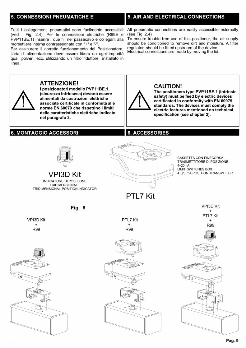
INDICATORE DI POSIZIONE TRIDIMENSIONALE
TRIDIMENSIONAL POSITION INDICATOR
VPI3D Kit
PTL7 Kit
CASSETTA CON FINECORSATRASMETTITORE DI POSIZIONE 4÷20mALIMIT SWITCHES BOX4...20 mA POSITION TRANSMITTER
VPI3D Kit+
R99
PTL7 Kit+
R99
VPI3D Kit+
PTL7 Kit+
R99
Fig. 6
Tutti i collegamenti pneumatici sono facilmente accessibili(vedi Fig. 2.4). Per le connessioni elettriche (R99E ePVP11BE.1) inserire i due fili nel passacavo e collegarli allamorsettiera interna contrassegnata con "+" e "-".Per assicurare il corretto funzionamento del Posizionatore,l'aria di alimentazione deve essere libera da ogni impuritàquali polveri, ecc. utilizzando un filtro riduttore installato inlinea.
All pneumatic connections are easily accessible externally(see Fig. 2.4)To ensure trouble free use of this positioner, the air supplyshould be conditioned to remove dirt and moisture. A filterregulator should be fitted upstream of the device.Electrical connections are made by moving the lid.
5. CONNESSIONI PNEUMATICHE E 5. AIR AND ELECTRICAL CONNECTIONS
6. MONTAGGIO ACCESSORI 6. ACCESSORIES
ATTENZIONE!I posizionatori modello PVP11BE.1 (sicurezza intrinseca) devono essere alimentati da costruzioni elettriche associate certificate in conformità alle norme EN 60079 che rispettino i limiti delle caratteristiche elettriche indicate nel paragrafo 2.
CAUTION!The positioners type PVP11BE.1 (intrinsic safety) must be feed by electric devices certificated in conformity with EN 60079 standards. The devices must comply the electric features mentioned on technical specification (see chapter 2).
Pag. 10
1. Controllare che tutti i collegamenti siano corretti.2. Alimentare il posizionatore.
N.B. Il posizionatore viene fornito per la rotazione insenso antiorario. Per invertire il senso di rotazione èsufficente seguire la procedura descritta al paragrafo10.
3. Inviare un segnale di 3 psi o 4 mA al posizionatore eagire sulla vite di zero (Fig. 7) sino a far partire lavalvola.4. Girare la vite di zero, molto lentamente, in sensocontrario sino a portare la valvola in posizione di iniziocorsa.5. Inviare un segnale di 15 psi o 20 mA al posizionatoree verificare l'apertura della valvola.6. Se la corsa della valvola non corrisponde a quella
desiderata, allentare il dado "1" e agire sulla vitedi correzione campo. Ruotare la vite in senso orario peraumentare il campo e in senso opposto per diminuirlo.Durante questa operazione tenere presente che ognirotazione completa della vite, corrisponde a circa 2° dirotazione della valvola. Serrare il dado "1".7. Inviare un segnale di 3 psi o 4 mA al posizionatore eripetere la correzione di zero.8. Inviare un segnale di 15 psi o 20 mA al posizionatoree verificare l'apertura della valvola. Se necessarioripetere le operazioni da 6 a 7 sino al conseguimentodei valori desiderati.
1. Check the piping connections2. Feed the positioner.
Note: The positioner is suplied with anticlockwiserotation as standard. To reverse the way of rotationfollows the procedure on item 10.
3. Send a 3 psi or 4mA signal to the positionerreaching the actuator starting point, by shifting the zeroadjustment screw (Fig.7)4. Turn slightly the screw (Fig. 7) to the oppositedirection until the actuator is come back to the startingposition.5. Send a 15 psi or 20mA signal to the positioner andcheck the valve opening.6. In case of the valve stroke is still incorrect, thenrelease the screw nut "1" and turn the spanadjustment screw (Fig. 7). Turn that screw onclockwise direction to increase the span oranticlockwise to reduce it. During the operation mindthat any complete turn of screw means about 2° ofvalve rotation angle. Now lock the nut "1".7. Repeat the zero adjustment still sending a 3 psi or4mA signal to the positioner.8. Send again a 15 psi or 20mA signal to the positionerand check the valve opening.If necessary, repeat the operation of items 6 and7 untilthe right calibration is reached.
CORREZIONE CAMPOSPAN ADJUSTMENT
1Fig. 7 (R99E)
7. MESSA IN FUNZIONE 7. COMMISSIONING
A
B
CORREZIONE ZEROZERO ADJUSTMENT
CONNESSIONI ELETTRICHE 4÷20mAELECTRICAL CONNECTIONS 4÷20mA
Pag. 11
Parecchie applicazioni richiedono che la valvola esegua i 90°di corsa con il segnale in ingresso ridotto del 50% (3÷9psi o9÷15psi per R99P ; 4÷12mA o 12÷20mA per R99E). Nel casosia richiesta questa operazione è sufficiente allentare ildado "1" Fig. 7, far compiere alla vite di regolazione campocirca 22 giri completi in senso orario e ripetere la proceduradel capitolo precedente sostituendo i segnali in ingresso.
Many applications require the 90° of valve stroke with a 50%reduced input signal (3÷9 psi or 9÷1 5 for R99P; 4÷12 or12÷20 mA for R99E).In this case release the screw nut "1" (Fig. 7) and turnthe span adjustment of about 22 periods on clockwisedirection and repeat the procedure of the previous chapter(by using the suitable input signals).
8. FUNZIONAMENTO IN SPLIT RANGE 8. SPLIT RANGE OPERATION
Con i posizionatori R99 è possibile regolare separatamentele velocità di apertura e chiusura della valvola, agendo sulleviti "A" e"B" Fig.7. Per diminuire le velocità, allentare i dadi dibloccaggio e ruotare le viti in senso orario. Per aumentare levelocità, allentare i dadi di bloccaggio e ruotare le viti insenso antiorario. La massima velocità si ottienetogliendo del tutto le viti "A" e"B"
A splitted opening / closing speed adjustment of the valveshould be made by means the nut screws "A" & "B" (Fig.7).To rise the valve speed, release these nuts and turn thescrew on anticlockwise direction. The maximum speedis obtained by removing the nut screws "A" & "B"completely.
9. REGOLAZIONE VELOCITÀ VALVOLA 9. VALVE SPEED ADJUSTMENT
Il posizionatore viene fornito per la rotazione in sensoantiorario (Fig.10.1). Per invertire il senso di rotazione èsufficente seguire la procedura sotto:1) Allentare il dado blocca camma "C"2) Ruotare la camma in senso orario, portando il cuscinetto"D" all'incirca nella posizione in Fig.10.23) Serrare il dado "C".4) Ripetere la procedura del capitolo 7
The positioner is provided with anti-clockwise rotation (seefig. 10.1). To reverse the direction of rotation see thefollowing items:1) Release the nut "C"2) Rotate the cam wheel as the arrow on Fig.10.2 (clockwiserotation). Hold the bearing on "D" position.3) Lock the nut "C".4) Now repeat the procedure mentioned on chapter 7.
10. INVERSIONE DEL SENSO DI ROTAZIONE 10. ROTATION REVERSING
C
D
CAMMACAM
Fig. 10.1 Fig. 10.2
ATTENZIONE!Prima di compiere questa manovra, assicurarsi che il posizionatore non sia alimentato.
CAUTION!Before be over this operate, make sure that the positioner has not in pressure.
Pag. 12
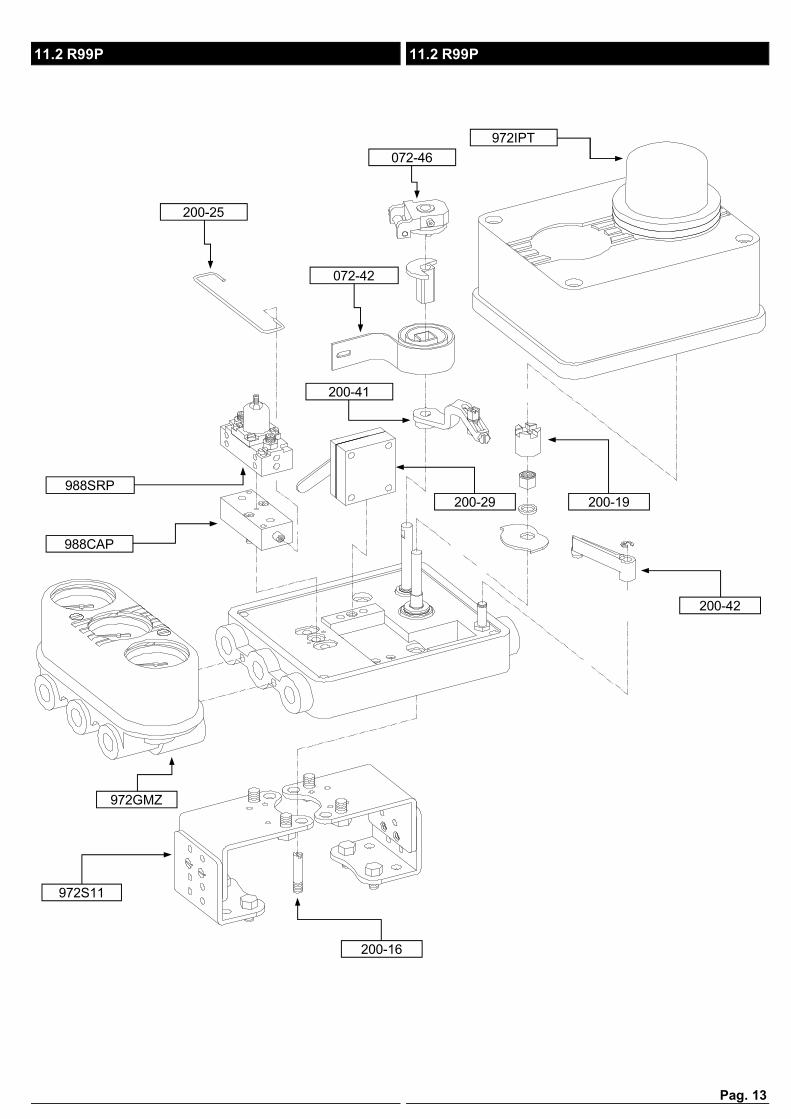
11. RICAMBI 11. SPARE PARTS
11.1 R99E e PVP11BE.1 11.1 R99E & PVP11BE.1
972IPT
072-46
072-42
200-25
200-32
200-41
988SRE
988CAE
200-30
200-42
110-145
200-31
200-16
972S11
972GMZ
200-19
200-44
110-164
073-105073-106
PVP11BE.1PVP11BE.1R99ER99E
INPUT mAINPUT VoltINPUT mAINPUT Volt
R99EPVP11BE.1
Pag. 13
972IPT
072-46
072-42
200-25
200-41
988SRP
988CAP
200-29
200-42
200-16
972S11
972GMZ
11.2 R99P 11.2 R99P
200-19
Pag. 14
13. MALFUNZIONAMENTO: SINTOMI, CAUSE E RIMEDI
13. TROUBLE: SYMPTOMS, CAUSES AND ACTION TO TAKE
Prima di mettere mano allo strumento, verificare quantosegue:- corretta alimentazione dello strumento- collegamenti pneumatici e di processo- buon funzionamento e stato della valvola
Before operating the unit, please check:- the unit proper supply- the pneumatic and process connections- the good operating conditions and status of the valve
SINTOMO CAUSA RIMEDIO
L'attuatore pendola e non si stabilizza.
Velocità di apertura e chiusura della valvola elevata.
Diminuire la velocità. Vedi capitolo 9
Mancato collegamento della porta "P2" dell'attuatore a semplice effetto.
Collegare la porta. Vedi capitolo 4.2
SYMPTOM CAUSE ACTION TO TAKE
Actuator hunting
Opening/Closing valve speed too high
Reduce the speed. See chapter 9
Connection "P2" missing on the single acting actuator
Connect the item "P2". See chapter 4.2
Errato dimensionamento tra attuatore e valvola; l'attuatore è sottodimensionato.
Utilizzare un attuatore di dimensioni maggiori adatto all'utilizzo del posizionatore.
Wrong sizing between actuator and valve; the actuator is undersize.
Use a bigger actuator suitable to operate with the positioner.
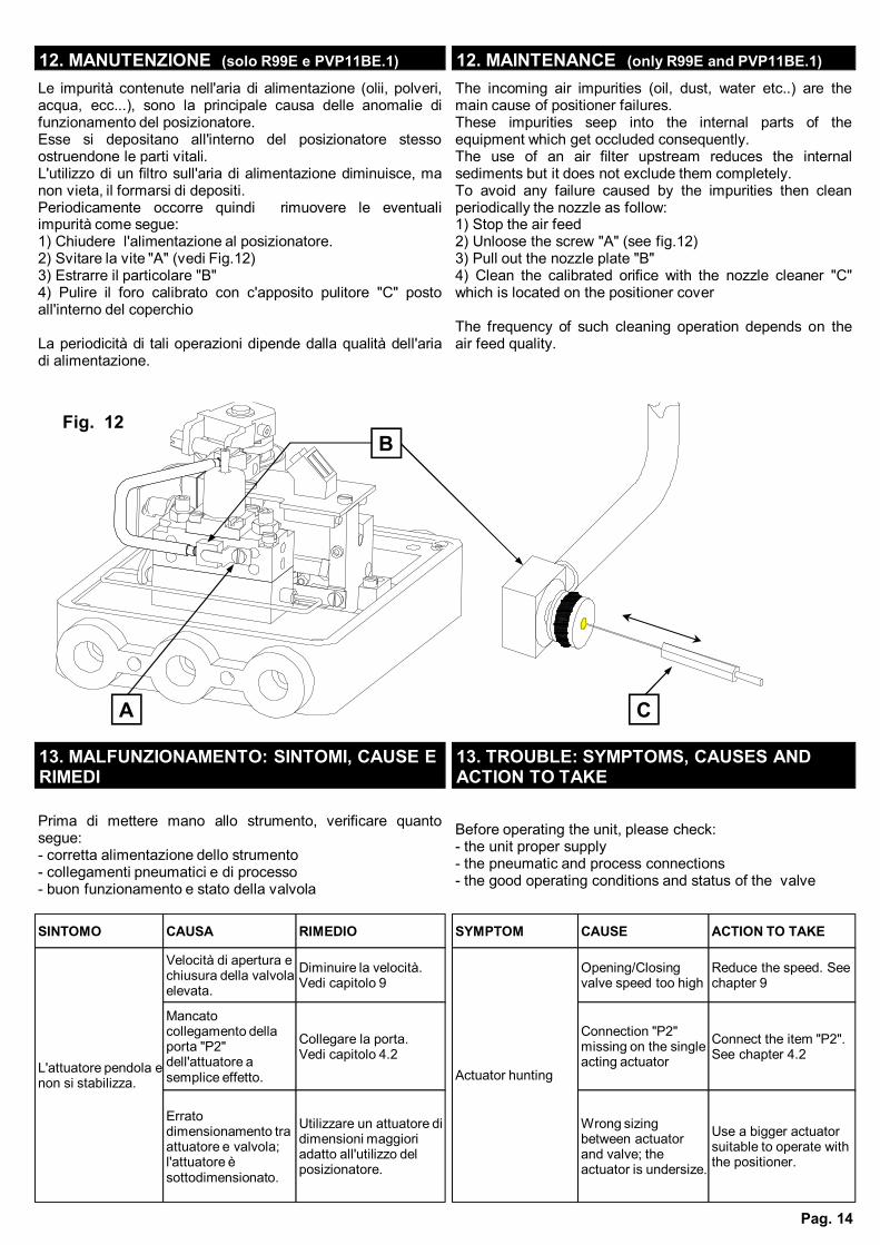
Le impurità contenute nell'aria di alimentazione (olii, polveri,acqua, ecc...), sono la principale causa delle anomalie difunzionamento del posizionatore.Esse si depositano all'interno del posizionatore stessoostruendone le parti vitali.L'utilizzo di un filtro sull'aria di alimentazione diminuisce, manon vieta, il formarsi di depositi.Periodicamente occorre quindi rimuovere le eventualiimpurità come segue:1) Chiudere l'alimentazione al posizionatore.2) Svitare la vite "A" (vedi Fig.12)3) Estrarre il particolare "B"4) Pulire il foro calibrato con c'apposito pulitore "C" postoall'interno del coperchio
La periodicità di tali operazioni dipende dalla qualità dell'ariadi alimentazione.
The incoming air impurities (oil, dust, water etc..) are themain cause of positioner failures.These impurities seep into the internal parts of theequipment which get occluded consequently.The use of an air filter upstream reduces the internalsediments but it does not exclude them completely.To avoid any failure caused by the impurities then cleanperiodically the nozzle as follow:1) Stop the air feed2) Unloose the screw "A" (see fig.12)3) Pull out the nozzle plate "B"4) Clean the calibrated orifice with the nozzle cleaner "C"which is located on the positioner cover
The frequency of such cleaning operation depends on theair feed quality.
12. MANUTENZIONE (solo R99E e PVP11BE.1) 12. MAINTENANCE (only R99E and PVP11BE.1)
Fig. 12
A
B
C
Pag. 15
L'attuatore si muove molto lentamente.
Velocità di apertura e chiusura della valvola bassa.
Aumentare la velocità. Vedi capitolo 9
Actuator motion is too slow.
Opening/Closing valve speed too low
Increase the speed. See chapter 9
Il posizionatore non regola correttamente apertura e chiusura dell'attuatore.
Connessioni pneumatiche tra posizionatore e attuatore invertite
Correggere.Vedi capitolo 4
Coordinamento tra attuatore e posizionatore errato.
Correggere.Vedi capitolo 4
Collegamenti elettrici invertiti.
Correggere.Vedi capitolo 5
La camma si trova in posizione errata
Correggere.Vedi capitolo 10
L'attuatore non compie il campo desiderato
Regolazione di campo errata
Correggere.Vedi capitolo 7
L'attuatore non parte dalla posizione desiderata
Regolazione di zero errata
Correggere.Vedi capitolo 7
Mancanza del segnale di comando
Controllare e correggere.
Mancanza aria di alimentazione
Controllare e correggere.
Positioner with wrong control action
Pneumatic connection between actuator and positioner has been inverted
Reverse its positionSee chapter 4
Actuator and positioner coupling is not correct
Adjust.See chapter 4
Electric connections has been inverted.
Adjust.See chapter 5
The position of cam wheel is wrong
Adjust.See chapter 10
Actuator span inadequate
Span adjustment is wrong
Adjust.See chapter 7
Actuator start point shifted
Zero adjustment missing
Adjust.See chapter 7
Control signal missing
Check and adjust
Supply air missing Check and adjust
L'attuatore si muove troppo velocemente.
Velocità di apertura e chiusura della valvola elevata.
Diminuire la velocità. Vedi capitolo 9
Actuator motion is too high.
Opening/Closing valve speed too high
Reduce the speed. See chapter 9
Strozzatura ostruita da depositi di impurità
Correggere.Vedi capitolo 12
The orifice is obstruct from impurity
Reverse its positionSee chapter 12
SINTOMO CAUSA RIMEDIO SYMPTOM CAUSE ACTION TO TAKE