Embed Size (px)
Citation preview
N-Class Divisions U.S. Navy Requirements for Fire Protection and Testing
USMAN SORATHIA Fire Protection Group
NAVAL SURFACE WARFARE CENTER, CARDEROCK DIVISIONWEST BETHESDA, MD 20817-5700301-227-5588; 301-227-4814 (Fax)
2
Outline
• History of Fires• Shipboard Assessment of Fire Curves• Adoption of Hydrocarbon pool fire curve• N-Class Divisions• Fire resistance test method, MIL-STD-3020• Approved N-Class Systems• Penetrations Through FZ Boundary• Summary

3
Fire: USS Forrestal in 1967
An accidentally fired air to ground rocket hit a fully fueled and armed A-4 Skyhawk. Blazing JP-5 fuel spilled onto the flight deck. Suddenly, two A-4s ahead of Lt. Cmdr John S. McCain’s plane were engulfed in flaming jet fuel. A bomb dropped to the deck and came to rest in a pool of burning fuel. The awful conflagration left 132 Forrestal crewman dead, and 62 more injured and two missing and presumed dead.

4
Fire: USS Enterprise in 1969
During the arming of an F-4 Phantom, a MK-32 Zuni rocket warhead attached to an F-4 Phantom detonated setting off fires and additional explosions. 27 lives were lost, and an additional 314 people were injured. The fire had destroyed 15 aircraft.

5
Fire: USS Belknap in 1975
Fire from a collision between the USS KENNEDY (CV-67) and the USS BELKNAP (CG 26) resulted in significant melting of aluminum deckhouse. The fire spread into the ship below. This influenced the Navy to improve the survivability of aluminum structures through mineral wool insulation. Use of steel in the deckhouse started with the DDG 51. Navy has experienced a resurgence of interest in the application of composites for topside structures because of weight savings and reduced maintenance.
6
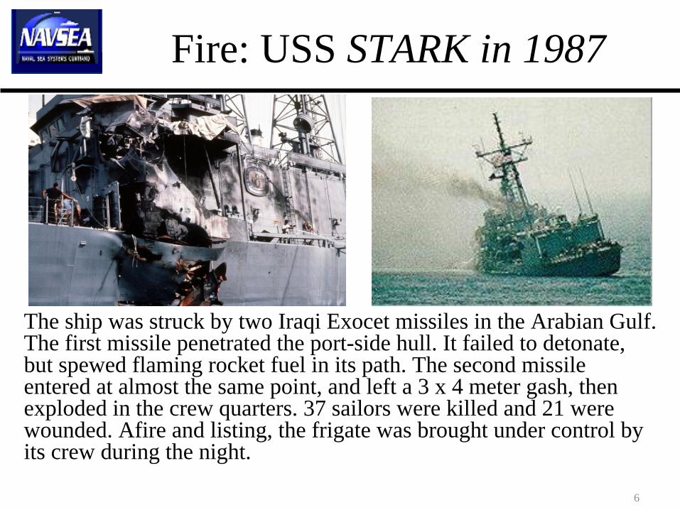
Fire: USS STARK in 1987
The ship was struck by two Iraqi Exocet missiles in the Arabian Gulf. The first missile penetrated the port-side hull. It failed to detonate, but spewed flaming rocket fuel in its path. The second missile entered at almost the same point, and left a 3 x 4 meter gash, then exploded in the crew quarters. 37 sailors were killed and 21 were wounded. Afire and listing, the frigate was brought under control by its crew during the night.

USS COLE in 2000
• In October 2000, the USS Cole (DDG 67) was attacked while it was harbored in the Yemeni port of Aden. Seventeen American sailors were killed.
8
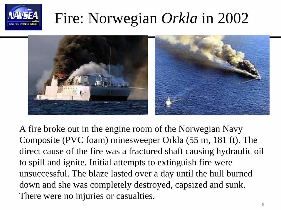
Fire: Norwegian Orkla in 2002
A fire broke out in the engine room of the Norwegian Navy Composite (PVC foam) minesweeper Orkla (55 m, 181 ft). The direct cause of the fire was a fractured shaft causing hydraulic oil to spill and ignite. Initial attempts to extinguish fire were unsuccessful. The blaze lasted over a day until the hull burned down and she was completely destroyed, capsized and sunk. There were no injuries or casualties.

9
Post Flashover Fire Curve• Following USS STARK incident, US
Navy conducted research to evaluate the tendency for fire spread from ship compartments after flashover.
• The tests were conducted in actual shipboard compartments on the US Navy’s fire test ship in Mobile, AL, the ex-USS SHADWELL LSD 15.
• Tests simulated a worse case flashover condition (diesel spray fire, 10 MW).
• The insulation mineral wool failed. • Fire insulation is typically tested against
ASTM E 119. • The fire threat used to simulate
flashover is much more severe than ASTM E 119 curve.
• The higher temperature exposure melted the fibers and destroyed the binder.
Fire exposure that simulated flashover in ex- USS SHADWELL is very close to the UL 1709 fire curve which is a rapid rise fire test.

ABS/NVR• The American Bureau of Shipping and the United States Navy formalized their
established strategic partnership through a Cooperative Agreement in 2003. ABS Naval Vessel Rules (ABS/NVR) were published in 2004. ABS/NVR is revised on a periodic basis.
• PEO Ships directed that the ABS classification process using Naval Vessel Rules (NVRs) would form a core part of the certification process for the DD(X), LCS and all future non-nuclear Navy surface ship procurements.
• Navy introduced N-Class Divisions in 2004, which is incorporated in NVR 1-2-1, Structural Fire Protection.
• Navy also introduced AN-Class Divisions. AN-Class Divisions are SOLAS/IMO approved A-Class Divisions with a requirement to pass the shock test. in accordance with MIL-S-901.
• For spaces where there are no flammable or combustible fluid systems and the survivability requirements do not include an unexpended missile fuel fire, AN-Class Divisions may be used in lieu of N-Class Divisions when approved by the Naval Technical Authority.
• Fire testing shall be conducted by an independent testing laboratory that is accredited to ISO/IEC 17025, General Requirements for the Competence of Testing and Calibration Laboratories. Accreditation to ISO/IEC 17025 shall be obtained from a recognized accreditation body, such as American Association for Laboratory Accreditation or International Code Council’s International Accreditation Services.

Navy N-Class Divisions• The Navy N-Class system for classifying fire resistant boundaries is analogous to the
commercial IMO system (e.g., A-Class divisions). However, some changes and modifications have been made to accommodate fire threats and combat environment.
• The key difference is the Navy N-Class fire exposure AFTER SHOCK TESTING. N- Class fire exposure uses the more severe temperature and heat flux requirements of a hydrocarbon (class B) fire exposure in accordance with the fire curve of UL-1709.
• An N-Class division boundary shall comply with the following:a. Constructed of steel or other equivalent material; "other equivalent material"
includes composite construction for topside structures when they pass the fire test requirements IAW DDS-078-1.
b. Prevent passage of smoke and flame to the end of the N-Class Division Fire Test, conducted in accordance with paragraph 5.5.1.2, for the specified period.
c. For composites, they shall be capable of supporting the maximum load (as defined in paragraph 5.5.1.3) for structural integrity fire testing to the end of the specified period.
– d. Limit the average (250 deg F) and peak (325 deg F) unexposed face temperature rise during the fire test within the time listed below:
Class N-60 60 minClass N-30 30 minClass N-0 0 min
12
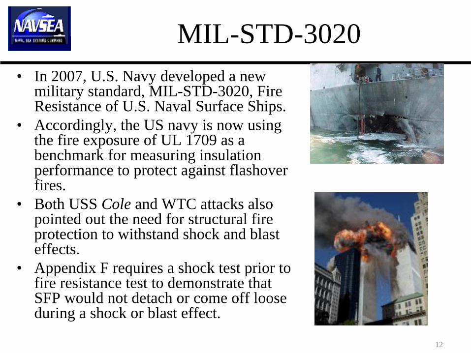
MIL-STD-3020• In 2007, U.S. Navy developed a new
military standard, MIL-STD-3020, Fire Resistance of U.S. Naval Surface Ships.
• Accordingly, the US navy is now using the fire exposure of UL 1709 as a benchmark for measuring insulation performance to protect against flashover fires.
• Both USS Cole and WTC attacks also pointed out the need for structural fire protection to withstand shock and blast effects.
• Appendix F requires a shock test prior to fire resistance test to demonstrate that SFP would not detach or come off loose during a shock or blast effect.

13
N-Class DivisionsN-Class:• Constructed of steel or other equivalent material.•"other equivalent material" includes polymer composite (FRP) construction for topside structures when they pass the fire test requirements of DDS- 078-1.
A-Class:• Constructed of steel or other equivalent material.• Polymer composite construction permitted in High Speed Craft Code.

14
N-Class DivisionsN-Class:• UL 1709 Fire Curve•heat flux of 204 ± 16 kW/m2;•temperature of 1,093 ± 111°C (2,000 ± 200°F).•Minimum duration of fire test is 30 minutes.
A-Class:• ISO 834 Standard fire curve •Minimum duration of fire test is 60 minutes.
Fire Curves
0
500
1000
1500
2000
2500
0 10 20 30 40 50 60
Time (Min)
Tem
pera
ture
(F)
ASTM E119 UL-1709 IMO
N-Class
A-Class

15
N-Class DivisionN-Class:• N-Class Division with SFP shall pass a MW shock test IAW MIL-S- 901 prior to the fire resistance test.
–No delamination or cracking of SFP–No failure of SFP attachment method such as large number of pins becoming loose
•The shock tested assembly shall then pass the intermediate fire resistance test.
A-Class: •No requirement.•AN Class requires a shock test.

16
N-Class Division• The shock test (medium weight,
Grade A) prior to fire resistance test is conducted IAW MIL-S-901D with intermediate scale 3048 x 1219 mm (10 feet x 4 feet) insulated bulkhead or deck test specimen.
• The medium weight shock test is a mechanical impact of a 1,361 kg (3,000 pound) hammer swinging through an arc and then hitting the anvil mounted on the underside of the table which holds the specimens.
• Shock Testing Insulation - April 2007-Rupert.wmv
Vertical Phase
Front
Incline Phase 30°Facing Down Incline
Incline Phase 30°Facing Across Incline
17
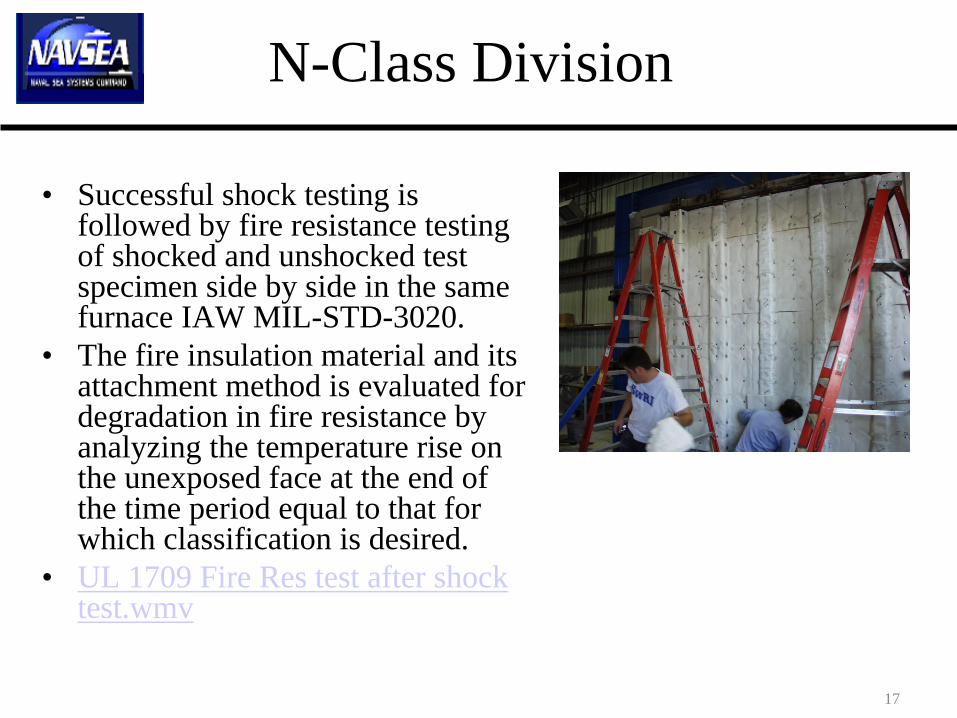
N-Class Division
• Successful shock testing is followed by fire resistance testing of shocked and unshocked test specimen side by side in the same furnace IAW MIL-STD-3020.
• The fire insulation material and its attachment method is evaluated for degradation in fire resistance by analyzing the temperature rise on the unexposed face at the end of the time period equal to that for which classification is desired.
• UL 1709 Fire Res test after shock test.wmv

18
N-Class Division Temperature on unexposed face
N-Class:• measured using Type K (Chromel-Alumel) thermocouples.•Nine thermocouples centered between the frame bays.•The thermocouples placed under dry felted pads as described in ASTM E 119 (6” x 6 ”x 0.375 ” thick).•Unexposed face temperature rise is higher (appx 50 deg F) from ASTM thermocouple pads than IMO thermocouple pads.
A-Class: •measured by 12 mm diameter copper disc (0.2 mm thick) thermocouples. •temperature rise from Five thermocouples;•thermocouple covered with a 30 mm square insulating pad (2 mm thick).
19
N-Class Division Structural Integrity Under Fire
• Steel: Not required to be tested under load. – demonstrated by analysis to illustrate that the stresses will not exceed
values acceptable to the NTA. • Aluminum: Not required to be tested under load.
– the avg. temperature of the structural core shall not rise more than 200oC over initial temperature.
• Polymer composites: Tested with the maximum load. – The maximum load for structural integrity fire testing is two times the
sum of the dead load, the design live load, and the firefighting live load. – The dead load is the weight of the structure. The live load is the weight
of equipment and personnel. The firefighting live load is assumed to be 50 pounds per square foot.
– There shall be no collapse of the structure or joint, or rupture of the structure for the period specified. The maximum average temperature on the unexposed side of the composite system shall not exceed the critical temperature of the composite where structural properties degrade rapidly (see Appendix A).

20
TEST SET UP
Photograph of FRP deck (overhead) test setup (unexposed side). Structural loading was provided by hydraulic jacks.

Penetrations Through FZ Boundary
• 2.2.2.1 Penetrations through Bulkheads and Decks
• Penetrations in fire resistant divisions shall be classified consistent with the rating of the boundary which they penetrate except where specified otherwise.
• NAVSEA STD Drawing 803-5184182 applies to all cable, pipe and vent penetrations though fire insulated boundaries.
• Details U and V require 12-in. insulation wrap on all penetrations through FZ boundary Recently Navy tested cable, pipe, and ventilation ducting penetrations with and without 12” insulation wrap.

Penetrations Through FZ Boundary
• CABLES (MCT):
• IN BOTH RESTRICTED AND UNRESTRICTED ORIENTATIONS, BOTH SMALL AND LARGE CABLE PENETRATIONS WITHOUT INSULATION WRAP DID NOT MEET THE CRITERIA.
• IN BOTH RESTRICTED AND UNRESTRICTED ORIENTATIONS, BOTH SMALL AND LARGE CABLE PENETRATIONS WITH 12-IN. INSULATION WRAP MET THE CRITERIA
• DRY PIPES:
• ONLY THE SMALL DRY PIPE PENETRATION WITH INSULATION WRAP MET THE CRITERIA IN UNRESTRICTED ORIENTATION.
• WET PIPES
• THE SMALL WET PIPE PENETRATION WITH INSULATION WRAP MET THE CRITERIA IN UNRESTRICTED ORIENTATION.
• THE LARGE WET PIPE PENETRATION WITH INSULATION WRAP MET THE CRITERIA IN BOTH ORIENTATIONS.
• VENT DUCT
• IN BOTH UNRESTRICTED AND RESTRICTED ORIENTATIONS, THE VENT DUCT WITH AND WITHOUT INSULATION WRAP DID NOT MEET THE CRITERIA.

23
Small Scale Screening Test
• In the current competitive business environment, the U.S. Navy is often called upon to qualify new materials and systems.
• For new SFP systems, 4x4 ft steel division in deck orientation which met the unexposed face temperature rise requirements of less than 250oF ( with 30 deg margin of safety) also met the N- 30 requirements in full scale deck test.
• New insulation systems proposed for use by the Navy must first pass the small scale fire tests prior to the investment of resources into full scale qualification process.
Small scale (4x4 ft) vs Full scale (12x13.5 ft)
0
50
100
150
200
250
300
350
400
450
500
0 10 20 30 40 50 60 70
Time, mins
Une
xpos
ed fa
ce te
mp.
, deg
F
Small scale (4x4 ft)Full scale (12x13.5 ft)

Effect of I vs 2 Layers of Insulation and AL-foil
Plate 3: FMMP, 1 layer, 2”: 30.5 minPlate 4: FMMP, 2 layers, 1”, with AL-foil: 35 minPlate 5: FMMP, 2 layers, 1”, without AL-foil: 31.6 min

Comparison Between A 60 and N-30
N-30 Test Results
N-30 Design
A-60 Design
Furance Temperature
0
100
200
300
400
500
600
0 5 10 15 20 25 30 35 40
Time (minutes)
Une
xpos
ed F
ace
Tem
pera
ture
(°F)
0
200
400
600
800
1000
1200
1400
1600
1800
2000
Furn
ace
Tem
pera
ture
(°F)
The test specimens were chosen to represent an approved N-30 design (47 mm, 1.875 in. AFPM) and an approved A-60 design (USCG approved 6pcf, 38 mm thick AES fiber). The A-60 design failed at 18.9 minutes into the N-30 test, while in the A-60 test of the N-30 design lasted 87 minutes (27 minutes beyond the 60 minute criteria for the A-60 test).

26
SUMMARY
• U.S. Navy fire performance requirements are now governed by the ABS Naval Vessel Rules.
• USN has introduced N-Class Divisions as part of the Lessons Learned from USS COLE and WTC attacks.
• The Navy N-Class Division system is used to classify fire resistant boundaries. • The N-Class division is analogous to the commercial International Maritime
Organization (IMO) system. The key difference is that N-Class divisions are designed to protect against structural failure and prevent the passage of fire and smoke when exposed to a rapid rise hydrocarbon pool fire exposure (UL-1709) after shock testing.
• MIL-STD-3020 provides the fire resistance test method for N-Class Divisions. • The N-Class divisions now form a core part of the certification process for the
DD(X), LCS and all future non-nuclear Navy surface ships.• Navy has tested and approved several N-30 systems for use in LCS, DDG
1000, and CVN-78.• Navy has tested and found that N-Class penetrations through FZ boundary
need to be insulated.

27
Future Need: Light Weight Insulation in Ships
• New ships have 100+ tons of insulation.
• Fire insulation (N-30, restricted application) weighs 1-1.3 psf.
• Absolute need for light weight fire insulation (< 1 psf).
• Navy investment into development of fire insulation materials in the last 3 yrs > $5M
• Current R & D programs include– Development of Panel
system