Embed Size (px)
Citation preview
13
Mechanical Advanced
Machining ProcessesUNIT 11 MECHANICAL ADVANCED MACHINING PROCESSES
Structure 11.1 Introduction
Objectives
11.2 Abrasive Jet Machining 11.2.1 Parametric Analysis 11.2.2 Process Capabilities and Applications
11.3 Ultrasonic Machining 11.3.1 Ultrasonic Machining System 11.3.2 Mechanics of Cutting 11.3.3 Parametric Process Analysis 11.3.4 Process Capabilities and Applications
11.4 Abrasive Flow Machining 11.4.1 Working Principle of Abrasive Flow Machining 11.4.2 Abrasive Flow Machining System 11.4.3 Process Variables 11.4.4 Process Performance and Applications
11.5 Summary
11.6 Key Words
11.7 Answers to SAQs
11.1 INTRODUCTION
There are various kinds of machining/finishing processes which fall under the category of mechanical type of advanced machining processes (MAMPs). In this unit, a brief introduction to three types of processes (AJM, USM and AFM), their working principles, and applications are discussed.
Mechanical type of AMPs can be divided into two categories, i.e., machining processes and finishing processes as shown in Unit 10. First category includes the processes like abrasive jet machining (AJM), ultrasonic machining (USM), water jet machining (WJM), and abrasive water jet machining (AWJM). The second category includes abrasive flow machining (AFM) and magnetic abrasive finishing (MAF). The second category of processes (i.e., finishing processes) are not used for bulk material removal, for correcting the machining defects, or for shaping the components. Rather, they are used for surface finishing. However, AFM is also used for radiusing and deburring. Usually, these processes are not used for correcting the tolerances also.
Objectives After studying this unit, you should be able to
• know various mechanical types of advanced machining processes,
• identify applications of AJM, USM and AFM, and
• choose a type of process for the given workpiece if it can be machined by any of these (AJM, USM and AFM) processes.
11.2 ABRASIVE JET MACHINING
In abrasive jet machining (AJM), a stream of very fine abrasive particles suspended in inert gas is made to strike the workpiece surface at high velocity ranging between
14
Non-conventional Material Removal Processes
200-400 m/s. The impact of high velocity abrasive particles, with the work surface, induces high surface stress in localized regions. This stress is often sufficient to cause cracking and fracture of the work material in tiny regions, resulting into material removal by erosion. This process has been employed for cutting, cleaning, etching, polishing and deburring. This method of material removal is quite effective on hard and/or brittle materials (viz., glass, silicon, tungsten, ceramics, etc.) but not so effective on soft materials like aluminum, rubber, etc.
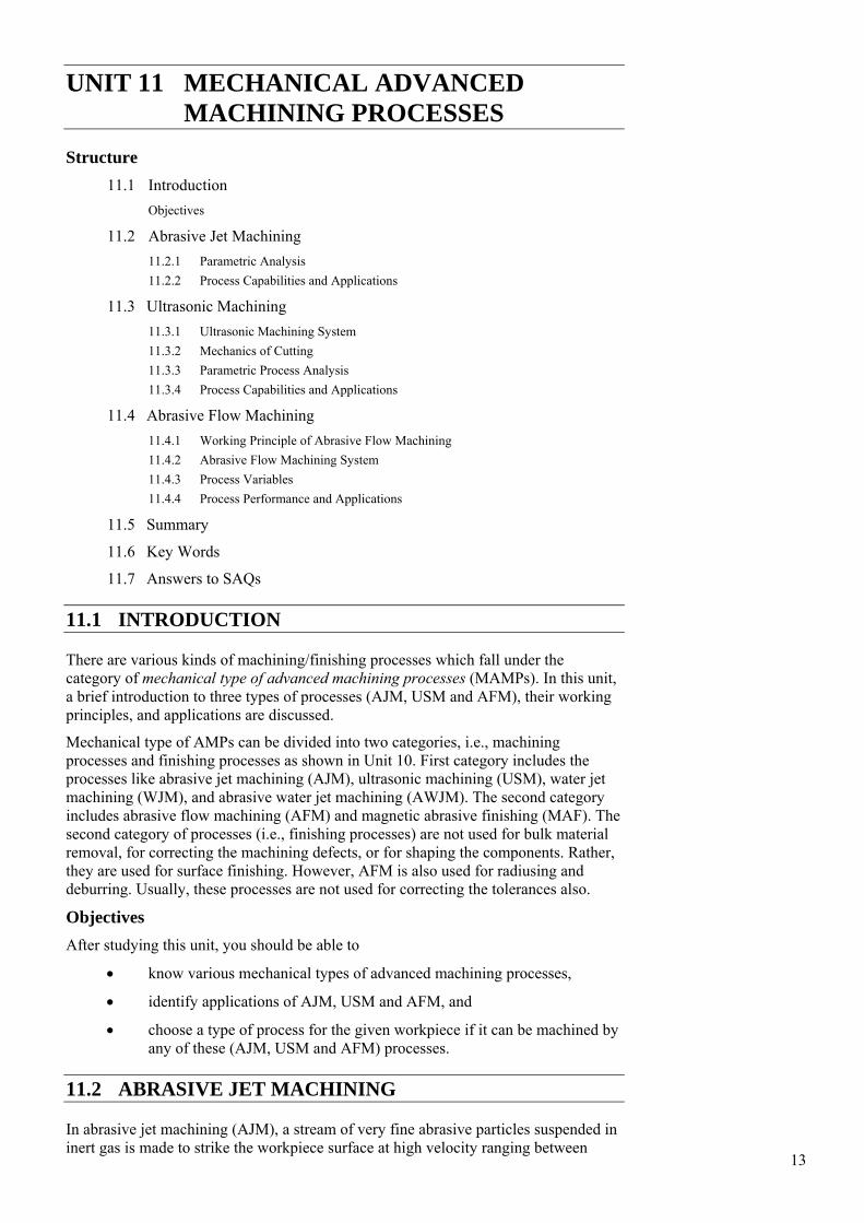
An abrasive jet machining (AJM) system comprises the following sub-systems/ elements : gas propulsion system, abrasive feeder, mixing chamber, nozzle, and abrasives. For gas propulsion system, high pressure gas (air, nitrogen, or CO2) is supplied either by a compressor or a cylinder to propel the abrasive particles to the mixing chamber. The gas should be dry and clean. In case of a compressor, air filter cum drier is used to avoid water/oil contamination of abrasive particles. The gas to be used should be nontoxic, cheap, and should have low divergence. It should be easily available. Quantity of abrasives supplied by the abrasive feeder to the mixing chamber is controlled by a vibrating sieve built into feeder (Figure 11.1). During the passage of high pressure mixture of gas and abrasive through the nozzle, the pressure energy is converted into kinetic energy which is utilized for material removal. To prevent the contamination of the surroundings, abrasive jet machining is normally carried out in a sealed chamber. Vacuum dust collector can be employed for this purpose.
Figure 11.1 : Abrasive Jet Machining (AJM) Setup
AJM nozzle is usually made of tungsten carbide or sapphire (usual life = 300 hr) with circular or rectangular cross-section. The nozzle material should have high resistance to wear. The nozzle pressure is generally maintained between 2-8.5 kgf/cm2 depending upon the workpiece material, desired accuracy, etc.
Wear of the nozzle results in irregular and stray cutting and poor work accuracy. Stray cutting can be controlled by the use of masks made of soft materials like rubber (for less accurate works) or metals (for more accurate works). Mask is applied to cover that part of the job surface where machining is not desirable.
Aluminum oxide (Al2O3), silicon carbide (SiC), glass beads, crushed glass, and sodium bicarbonate are some of the abrasives (size varies from 10 μm – 50 μm) used in AJM. Selection of abrasive depends upon the type of work material to be machined, desired material removal rate (MRR), and required machining accuracy. Al2O3 is good for cleaning, cutting, and deburring while SiC is also used for the similar applications but for harder work materials. For obtaining matt finish, glass beads are good. Small abrasive particles are used for cleaning and polishing, while large particles perform better during cutting. The abrasive particles should have sharp and irregular shape, and should be fine enough to remain suspended in the carrier gas. Furthermore, the abrasives should be cheap. Reuse of the abrasives is not recommended because of the two reasons : contaminated abrasives may block the nozzle passage, whereas the cutting ability of used abrasive is much lower.
15
Mechanical Advanced Machining Processes
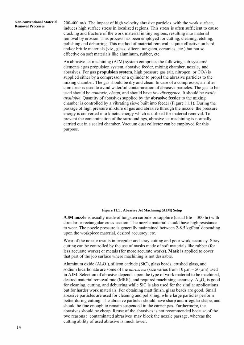
11.2.1 Parametric Analysis Important parameters that affect material removal rate in AJM are : stand-off-distance (i.e., SOD, or sometimes called as nozzle-tip-distance, NTD), type and size of abrasive particles, flow rate of abrasive, gas pressure, type of work material, and feed rate. The effects of these parameters on process performance are discussed below. Relationships between stand-off-distance and volumetric material removal rate (MRRv) as well as linear material removal rate (MRRι) are shown in Figure 11.2. A change in the shape of the machined cavity with a change in SOD is illustrated in Figure 11.3. In a range of SOD which usually varies from 0.75 to 1.0 mm, the MRR is maximum. A low value of SOD improves accuracy, decreases kerf width, and reduces taper in the machined groove. However, light operations like cleaning, frosting, etc. are conducted with a large SOD (say, 12.5 - 75 mm).
Figure 11.2 : Variation in Linear and Volumetric Material Removal Rate
with a Change in Stand-off-Distance [Verma and Lal, 1984]
Figure 11.3 : Effect of Stand-off-distance on the Shape of the Machined Cavity
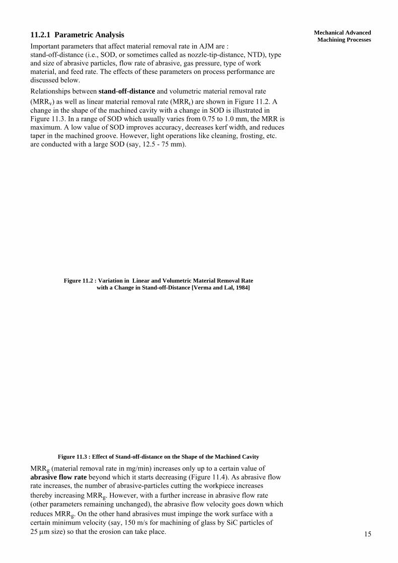
MRRg (material removal rate in mg/min) increases only up to a certain value of abrasive flow rate beyond which it starts decreasing (Figure 11.4). As abrasive flow rate increases, the number of abrasive-particles cutting the workpiece increases thereby increasing MRRg. However, with a further increase in abrasive flow rate (other parameters remaining unchanged), the abrasive flow velocity goes down which reduces MRRg. On the other hand abrasives must impinge the work surface with a certain minimum velocity (say, 150 m/s for machining of glass by SiC particles of 25 μm size) so that the erosion can take place.
16
Non-conventional Material Removal Processes
Kinetic energy (KE) of the abrasive particles is responsible for removal of material by erosion.
Mixing ratio (M, i.e., a ratio of volumetric flow rate of abrasive particles and volumetric flow rate of carrier gas) also influences MRRv. An Increase in the value of ‘M’ increases MRRv but a large value of ‘M’ may decrease jet velocity and sometimes may choke the nozzle. Thus, an optimum mixing ratio has been observed that gives maximum MRRv.
Figure 11.4 : Variation in Material Removal Rate with a Change in
Abrasive Flow Rate [Ingulli, 1967]
11.2.2 Process Capabilities and Applications
AJM is a low material removal rate process (approx. 0.015 cm3/min) and it can easily produce intricate details on hard and brittle materials. Production of narrow slots (0.12 - 0.25 mm), low tolerance (± 0.12 mm), good surface finish (0.25 - 1.25 μm), and sharp radius (≈ 0.2 mm) are some of the capabilities of the AJM process. AJM can machine without thermal damage to the work because the heat generation during machining is very small.
AJM is useful [Butler, 1980; Dombrowski, 1983] in the manufacture of electronic devices, deburring, marking on electronic and other products, deflashing small castings, cutting titanium foil, and drilling glass wafers. This process is also used for engraving registration numbers on the toughened glass, frosting glass surfaces, and cutting thin sectioned fragile components. It however, pollutes the working environment.
Example 11.1
During AJM, the mixing ratio used is 0.2. Calculate mass ratio if the ratio of density of abrasive and density of carrier gas is equal to 20.
(Note : Mass ratio = a
a g
MM +
⎛ ⎞⎜⎜⎝ ⎠
&& ⎟⎟ , where aM& is mass flow rate of abrasive and
is combined mass flow rate of abrasive and carrier both). gaM +&
Solution
We know, mixing ratio g
a
VV&&
=
Mass ratio, ggaa
aa
ga
a
VVV
MM
&&&
&&
ρ+ρρ
==α+
17
(Here, ρa and ρg are densities of abrasive and gas, respectively. aV& and gV& are volume flow rate of abrasive and carrier gas, respectively.)
Mechanical Advanced Machining Processes
or, 1 a a g g
a a
V VV
ρ + ρ=
α ρ
& &&
g g
a a
VV
ρ= ×ρ
&&
1 11 120 0.2
= + × = .25
or, 11.25
α =
α = 0.80
Example 11.2
Diameter of the AJM nozzle is 1.0 mm and jet velocity is 200 m/s. Find the volumetric flow rate (cm3/s) of the carrier gas and abrasive mixture, gaV +
& .
Solution
Cross-sectional area of the nozzle = π × (0.5)2 × 10− 2
= π × 25 × 10− 4 cm2
∴ = (π × 25 × 10a gV +& − 4) × 200 × 102
= π × 25 × 2
350 cm /sa gV + = π&
SAQ 1 (a) Examine whether the following statements are true (T) or false (F)
(i) The surface damage during AJM is significant.
(ii) AJM is a good process for cleaning metallic mould cavities.
(iii) AJM process can be employed to machine materials irrespective of whether they are insulator or conductor of electricity.
(iv) AJM and sand blasting are not similar kind of processes from application point of view.
(v) Shape of the abrasive particles affects MRR in AJM.
(vi) One obtains uniform diameter hole in AJM process. (b) Write all the correct answers (more than one answer may be correct).
(i) Materials not suitable for making a nozzle employed in AJM process may be (a) copper, (b) stainless steel, (c) sapphire, (d) WC.
(ii) In AJM, mixing ratio is governed by amplitude and frequency of vibration of the sieve. The frequency of vibration of sieve is (a) 50-60 Hz, (b) 10-15 kHz, (c) above 15 kHz.
(iii) In case of AJM, lower carrier gas pressure would yield (a) higher MRR and higher nozzle-life, (b) lower MRR and lower nozzle life, (c) higher nozzle life but lower MRR, (c) None of these.
(iv) In AJM, with the increase in stand-off-distance, the width of cut (a) decreases, (b) increases, (c) remains constant.
18
Non-conventional Material Removal Processes
(v) During AJM, increase in mass flow rate of abrasive particles would (a) decrease the value of mixing ratio, (b) increase the value of mixing ratio, (c) no definite effect on mixing ratio.
(vi) With an increase in abrasive particle size in AJM, (a) MRR as well as surface finish value increase, (b) MRR decreases but surface finish value increases, (c) MRR increases but surface finish value decreases.
(vii) The range(s) of size of abrasive particles which are not suitable for AJM are (a) 0.001-0.05 mm, (b) 0.1-0.5 mm, (c) 1-5 mm.
(viii) AJM is not suitable for machining of (a) Al, (b) Glass, (c) M.S.
(ix) In AJM, MRR decreases with (a) increase in NTD, (b) decrease in NTD, (c) no effect of NTD.
11.3 ULTRASONIC MACHINING
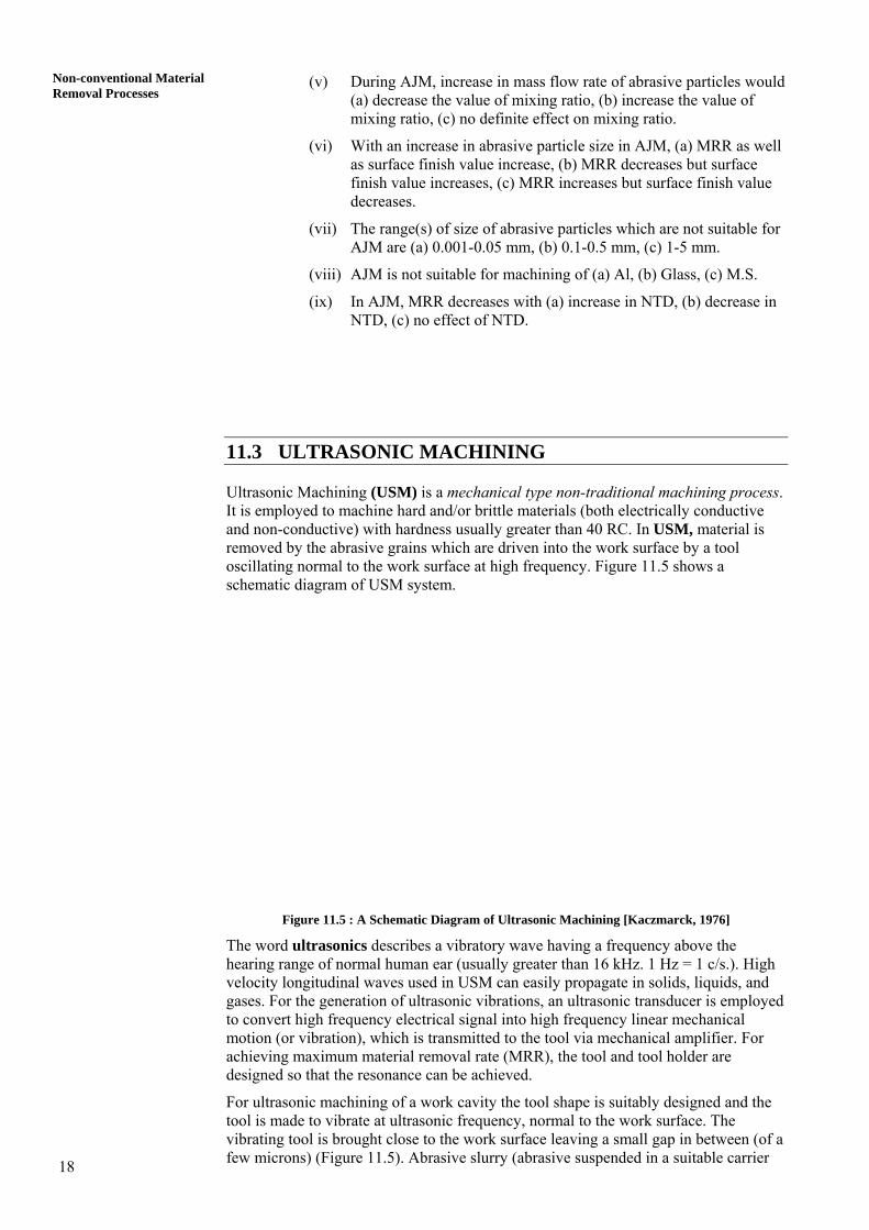
Ultrasonic Machining (USM) is a mechanical type non-traditional machining process. It is employed to machine hard and/or brittle materials (both electrically conductive and non-conductive) with hardness usually greater than 40 RC. In USM, material is removed by the abrasive grains which are driven into the work surface by a tool oscillating normal to the work surface at high frequency. Figure 11.5 shows a schematic diagram of USM system.
Figure 11.5 : A Schematic Diagram of Ultrasonic Machining [Kaczmarck, 1976]
The word ultrasonics describes a vibratory wave having a frequency above the hearing range of normal human ear (usually greater than 16 kHz. 1 Hz = 1 c/s.). High velocity longitudinal waves used in USM can easily propagate in solids, liquids, and gases. For the generation of ultrasonic vibrations, an ultrasonic transducer is employed to convert high frequency electrical signal into high frequency linear mechanical motion (or vibration), which is transmitted to the tool via mechanical amplifier. For achieving maximum material removal rate (MRR), the tool and tool holder are designed so that the resonance can be achieved.
For ultrasonic machining of a work cavity the tool shape is suitably designed and the tool is made to vibrate at ultrasonic frequency, normal to the work surface. The vibrating tool is brought close to the work surface leaving a small gap in between (of a few microns) (Figure 11.5). Abrasive slurry (abrasive suspended in a suitable carrier
19
Mechanical Advanced Machining Processes
medium) is circulated through the gap continuously to perform the cutting operation. The individual abrasive grains, on coming into contact with the vibrating tool, acquire high velocity and are propelled towards the work surfaces. High velocity bombardment of the work surface by the abrasive particles gives rise to the formation of a multitude of tiny stressed regions. The stress in these tiny regions is often sufficient to cause cracking, and fracture of the work surface resulting into material removal. The stress induced in the work surface is proportional to the KE of the abrasive particles hitting the work surface. The tool is constantly fed towards the workpiece to maintain a constant gap between the two. USM gives low MRR but is capable to machine intricate cavities in single pass in fragile or/and hard materials. A brittle material can be machined more easily than a ductile one. It is considered as a safe process because it does not involve high voltage, chemicals, large mechanical forces and heat.
11.3.1 Ultrasonic Machining System USM machines are available in the power output range of 40 W to 2.4 kW, and usually comprise five sub-systems, e.g., power supply, transducer, tool holder, tool, and abrasives. High power sine wave generator converts low frequency (50 Hz) electrical power to high frequency ( ≈ 20 kHz) electrical power. This high frequency electrical signal is transmitted to the transducer which converts it into high frequency low amplitude mechanical vibrations. In USM, either of the two types of transducers are used, i.e., piezoelectric type (for low power upto 900W) or magnetostrictive type (for high power, upto 2.4 kW). Piezoelectric crystals (say, quartz) generate a small electric current when compressed. Also, when an electric current is passed through the crystal, it expands; when the current is removed the crystal attains its original size. This effect is known as piezoelectric effect. Magnetostrictive transducer also works on a similar principle. Magnetostrictive transducers are made of nickel, or nickel alloy sheets and their efficiency (20-35%) is much lower than the piezoelectric transducers' (up to 95%), hence their cooling is essential to remove waste heat. The magnetostrictive type transducers are available with power capacity upto 2.4 kW. The US transducers can produce vibrations upto a maximum amplitude of 25 μm. Tool holder holds and connects the tool to the transducer (Figure 11.5), transmits the energy and, in some cases, amplifies the amplitude of vibration. Amplifying tool holders give as much as 6 times increased tool motion, and yield MRR upto 10 times higher than non-amplifying tool holder. However, amplifying tool holders are more expensive, demand higher operating cost and yield poorer surface quality. Material of the tool should have good acoustic properties, and high resistance to fatigue failure. Due measures should be taken to avoid ultrasonic welding between the transducer and the tool holder [Benedict, 987]. Commonly used materials for the tool holder are monel metal (for low amplitude applications), titanium and stainless steel. Tools are usually made of relatively ductile materials (brass, stainless steel, mild steel, etc.) to minimize tool wear rate (TWR). Value of the ratio of TWR and MRR depends upon the type of abrasive, workpiece material, and tool material combination. Surface finish of the tool affects the surface finish obtained on the workpiece. Silver brazing of the tool with tool holder minimizes the fatigue problem associated with screw attachment method. Abrasive material hardness, particle size, usable life time and cost are used as criteria for selecting the abrasive grains for USM. Commonly used abrasives in the order of increasing hardness, are Al2O3 , SiC and BB4C (Boron carbide). Abrasive hardness should be more than workpiece material hardness. MRR and surface finish obtained during USM also depend on the abrasive size. Finer grains result into lower MRR and better surface finish while reverse is true with coarser grains. Mesh sizes of grits generally used range from 240 to 800. Abrasive slurry consists of water and abrasives usually in 1 : 1 (by weight). However, it can vary depending upon type of operation, viz., thinner (or low concentration) mixtures are used while drilling deep holes, or machining complex cavities so that the slurry flow is more efficient. The slurry stored in a reservoir, is pumped to the gap formed by the tool and the work.
20
Non-conventional Material Removal Processes
11.3.2 Mechanics of Cutting The mechanism of material removal in USM has been studied by different researchers (Miller, 1957; Shaw, 1956; Kazantsev, 1965; Kainth, et. al, 1979). Theory proposed by M.C. Shaw (1956) is briefly explained below. Model Proposed by Shaw
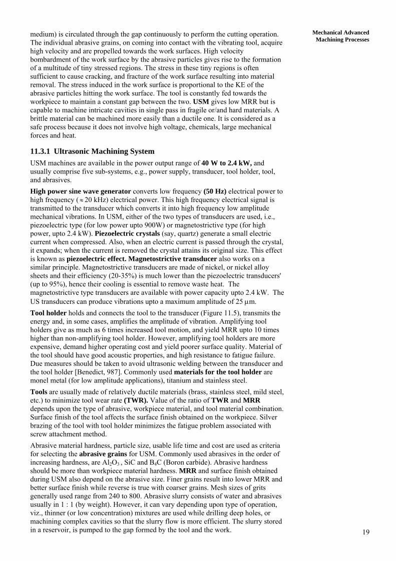
The mechanisms that can contribute to material removal in USM are : mechanical erosion, cavitation and chemical corrosion. Material removal due to cavitation under the tool, and chemical corrosion due to slurry medium are however, considered to be insignificant. Hence, material removal due to these two factors can be ignored. Contribution to the material removal by abrasive particle erosion due to throwing and hammering actions have been analyzed by Shaw as below. Abrasive particles are assumed to be spherical in shape having a uniform diameter of d. Abrasive particles suspended in a carrier fluid move under the high frequency vibrating tool. There are two possibilities when the vibrating tool hits the abrasive particles. If the size of the particle is small enough as compared to the gap between the tool and work surface, the particle will be thrown by the tool, to hit the work surface (throwing model). Large size abrasive grains on the other hand are likely to get entrapped between the work surface and the vibrating tool. Such particles would eventually be hammered down on to the work surface by the tool-hammering action. In both cases, it is assumed that a particle after hitting the work surface generates a crater of height h and radius r. It is also assumed that volume of the material removed from the workpiece is approximately proportional to the diameter of indentation (2 r). The volume of material (Vg) removed (shown by dashed lines in Figure 11.6) due to fracture per grit per cycle is given by
⎟⎠⎞
⎜⎝⎛ π= 3
g r34
21V (assuming hemispherical crater) . . . (11.1)
From the geometry of Figure 11.6(b),
22
2 h2d
2dr ⎟
⎠⎞
⎜⎝⎛ −−⎟
⎠⎞
⎜⎝⎛=
≈ dh (neglecting h2 term as h << d). . . . (11.2) From Eqs. (11.1) and (11.2), we can write Vg = K1 (hd)3/2 . . . (11.3) where, K1 is a constant. Number of impacts (N) on the workpiece by the grits in each cycle will depend upon the number of grits beneath the tool at any time. This is inversely proportional to the diameter of the grit (assumed spherical) as given below.
221
dKN = . . . (11.4)
where, K2 is a constant of proportionality. Let K3 be the probability of an abrasive particle under the tool being effective. Then volume (Vs) of material removed per second will be equal to the frequency (f) times the amount of material removed per cycle (Vc).
fdhKKKfVV
3
321cs .=×= . . . (11.5)
where, 2
23
321C d
hdKKKV
)(=
21
Mechanical Advanced Machining Processes
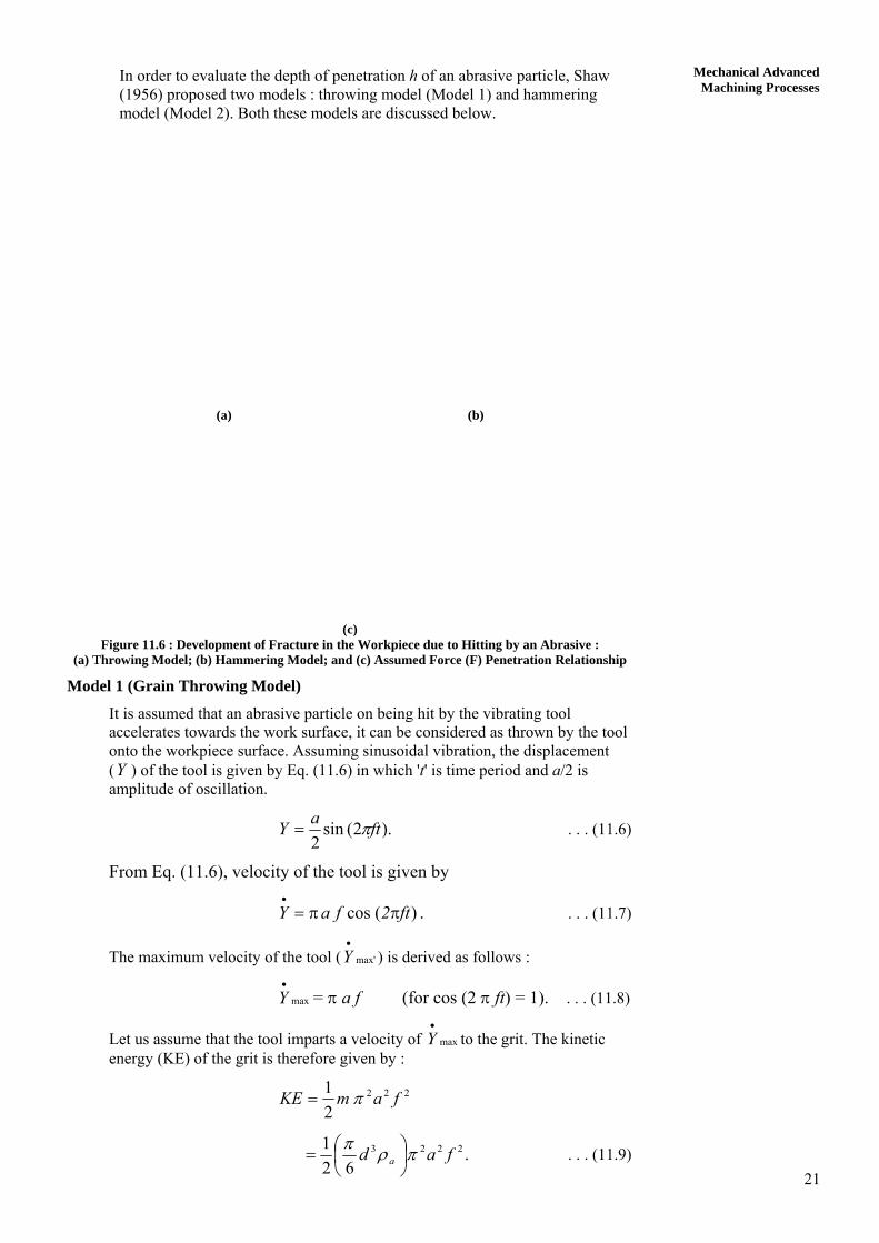
In order to evaluate the depth of penetration h of an abrasive particle, Shaw (1956) proposed two models : throwing model (Model 1) and hammering model (Model 2). Both these models are discussed below.
(a) (b)
(c) Figure 11.6 : Development of Fracture in the Workpiece due to Hitting by an Abrasive :
(a) Throwing Model; (b) Hammering Model; and (c) Assumed Force (F) Penetration Relationship
Model 1 (Grain Throwing Model)
It is assumed that an abrasive particle on being hit by the vibrating tool accelerates towards the work surface, it can be considered as thrown by the tool onto the workpiece surface. Assuming sinusoidal vibration, the displacement (Y ) of the tool is given by Eq. (11.6) in which 't' is time period and a/2 is amplitude of oscillation.
).2(sin2
ftaY π= . . . (11.6)
From Eq. (11.6), velocity of the tool is given by
. . . . (11.7) )(cos ft2faY ππ=•
The maximum velocity of the tool ( ) is derived as follows : max'
•
Y
= π a f (for cos (2 π ft) = 1). . . . (11.8) max
•
Y
Let us assume that the tool imparts a velocity of to the grit. The kinetic energy (KE) of the grit is therefore given by :
max
•
Y
222
21 famKE π=
.62
1 2223 fad a πρπ⎟⎠⎞
⎜⎝⎛= . . . (11.9)
22
Non-conventional Material Removal Processes
where, ρa is density of the abrasive particles.
It is assumed that when the thrown grit hits the works surface its KE is absorbed by the workpiece before the particle comes to rest after penetrating to a depth equal to ‘hth’. The work done by the grit (Wg) is given by
.thg Fh21W = . . . (11.10)
Here, it is assumed that variation in the penetration force (F) with the depth is triangular (Figure 11.6(c)).
Work done by a grit (Wg) can be equated to the KE of the impacting particle.
,62
121 2223 fadhF ath πρπ
⎟⎠⎞
⎜⎝⎛=
or, .Fdfa
6h a
3223
thρπ
= . . . (11.11)
The value of F can be derived from the workpiece property as follows : Mean stress acting on the workpiece surface (σW) is given by
dh
FAF
thW π
σ == (Using Eq. (11.2)).
.dhF thwσπ= . . . (11.12)
From Eqs. (11.11) and (11.12),
2 2 2 2 2.6
ath
wh a f d
ρ= π
σ
or, 6
ath
wh a f d
ρ= π
ρ . . . (11.13)
Material removal rate (MRRv) due to throwing action (Vth) can therefore be obtained using Eqs. (11.5) and (11.13).
3/ 42 2
5/ 21 2 3 6
ath
w
aV K K K d f
⎡ ⎤π ρ= ⎢ ⎥
σ⎢ ⎥⎣ ⎦ . . . (11.14)
Model 2 (Grain Hammering Model)
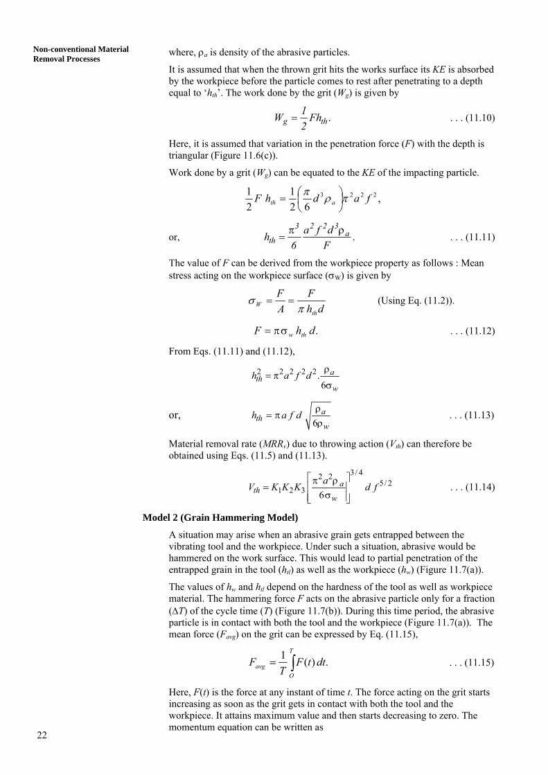
A situation may arise when an abrasive grain gets entrapped between the vibrating tool and the workpiece. Under such a situation, abrasive would be hammered on the work surface. This would lead to partial penetration of the entrapped grain in the tool (htl) as well as the workpiece (hw) (Figure 11.7(a)).
The values of hw and htl depend on the hardness of the tool as well as workpiece material. The hammering force F acts on the abrasive particle only for a fraction (ΔT) of the cycle time (T) (Figure 11.7(b)). During this time period, the abrasive particle is in contact with both the tool and the workpiece (Figure 11.7(a)). The mean force (Favg) on the grit can be expressed by Eq. (11.15),
∫=T
Oavg dttF
TF .)(1 . . . (11.15)
Here, F(t) is the force at any instant of time t. The force acting on the grit starts increasing as soon as the grit gets in contact with both the tool and the workpiece. It attains maximum value and then starts decreasing to zero. The momentum equation can be written as
23
Mechanical Advanced Machining Processes .
2)(∫ Δ⎟
⎠⎞
⎜⎝⎛≈
T
O
TFdttF . . . (11.16)
(a)
(b) (c) Figure 11.7 : (a) Partial Penetration of a Grit in the Tool and Workpiece; (b) Variation of Force (F)
with Time (T); and (c) Schematic Diagram of a Grain Hammering Model
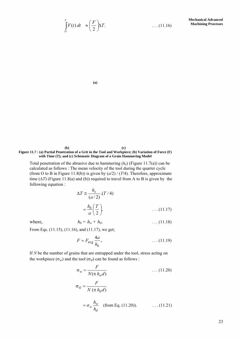
Total penetration of the abrasive due to hammering (hh) (Figure 11.7(a)) can be calculated as follows : The mean velocity of the tool during the quarter cycle (from O to B in Figure 11.8(b)) is given by (a/2) / (T/4). Therefore, approximate time (ΔT) (Figure 11.8(a) and (b)) required to travel from A to B is given by the following equation :
)4/.()2/(
Tah
T h≅Δ
.⎟⎠⎞
⎜⎝⎛=
2T
ahh . . . (11.17)
where, hh = hw + htl. . . . (11.18)
From Eqs. (11.15), (11.16), and (11.17), we get;
.hhaFF 4
avg= . . . (11.19)
If N be the number of grains that are entrapped under the tool, stress acting on the workpiece (σw) and the tool (σtl) can be found as follows :
) (σ
dhNF
ww π= . . . (11.20)
) ( t dhN
F
tll π=σ
tl
ww h
hσ= (from Eq. (11.20)). . . . (11.21)
24
Non-conventional Material Removal Processes
(a)
(b) Figure 11.8 : (a) Assumed Mode of Tool Vibration; and
(b) Various Positions of the Tool while Hitting Workpiece via a Grit
From Eqs. (11.4), (11.19) and (11.20),
)(4
2
2
dhKhdaF
whavgw π
=σ
)(
4
w2 tlw
avg
hhhKdaF+π
=
⎟⎟⎠
⎞⎜⎜⎝
⎛+π
=1
4
22
w
tlw
avg
hh
hK
daF. . . . (11.22)
We can define,
htl / hw = σw /σtl = j . . . (11.23) where, j is the ratio of hardness of workpiece material to the hardness of tool material. From Eqs. (11.22) and (11.23),
.)1(
4
2 +πσ=
jKaF
hw
avgw . . . (11.24)
Material removal rate from the workpiece due to hammering mechanism (Vh), can be evaluated using Eqs. (11.5) and (11.24) as follows
fdjKdFa
KKKVw
avgh
1/43/4
2321 )1(
4⎥⎦
⎤⎢⎣
⎡+πσ
= . . . (11.25)
25
Mechanical Advanced Machining Processes
From the computational results obtained using Eqs. (11.14) and (11.25), it is observed that Vh >> Vth.
11.3.3 Parametric Process Analysis
Performance (MRR, accuracy and surface finish) of the USM process depends upon the following parameters : Abrasives : (material size, shape, and concentration), Tool and tool holder : (material, frequency of vibration and amplitude of vibration), and Workpiece : (hardness).
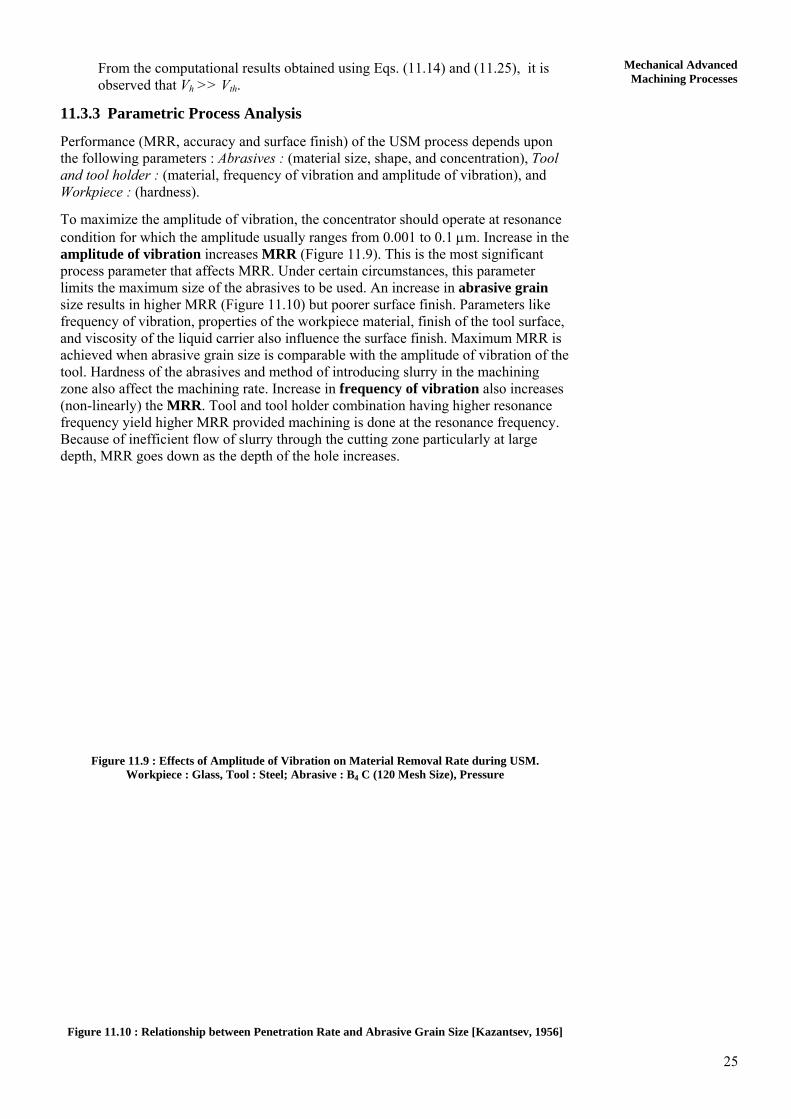
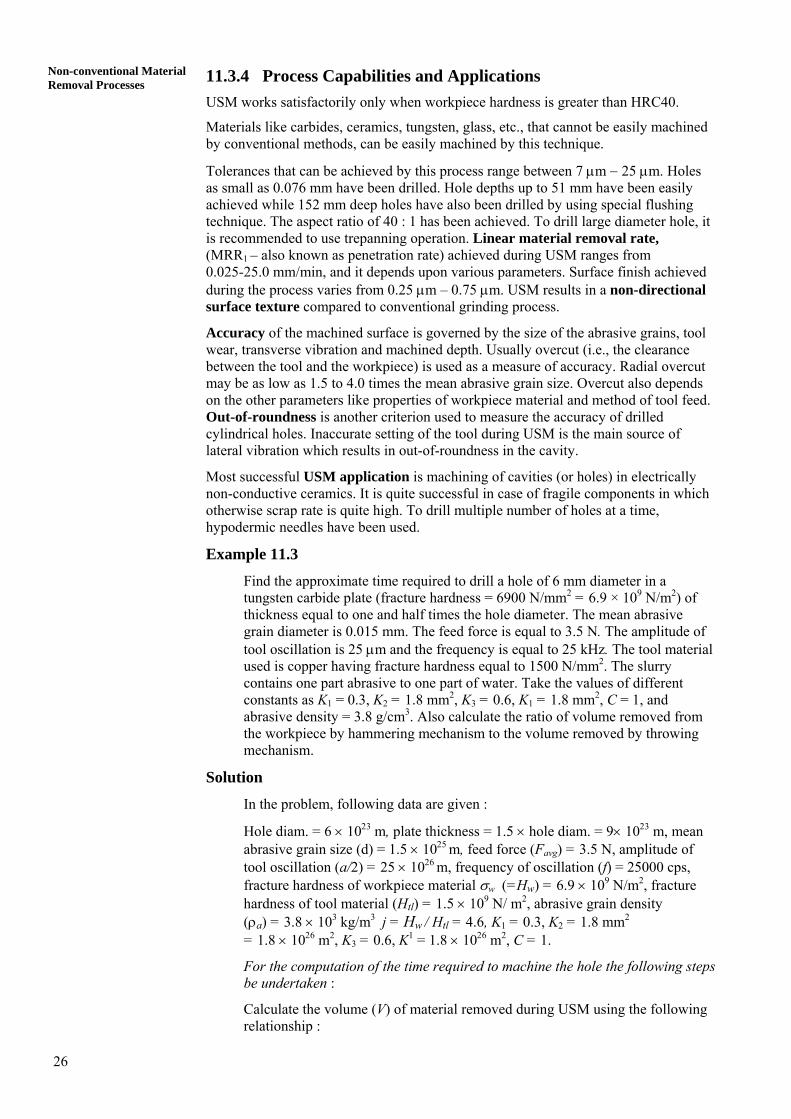
To maximize the amplitude of vibration, the concentrator should operate at resonance condition for which the amplitude usually ranges from 0.001 to 0.1 μm. Increase in the amplitude of vibration increases MRR (Figure 11.9). This is the most significant process parameter that affects MRR. Under certain circumstances, this parameter limits the maximum size of the abrasives to be used. An increase in abrasive grain size results in higher MRR (Figure 11.10) but poorer surface finish. Parameters like frequency of vibration, properties of the workpiece material, finish of the tool surface, and viscosity of the liquid carrier also influence the surface finish. Maximum MRR is achieved when abrasive grain size is comparable with the amplitude of vibration of the tool. Hardness of the abrasives and method of introducing slurry in the machining zone also affect the machining rate. Increase in frequency of vibration also increases (non-linearly) the MRR. Tool and tool holder combination having higher resonance frequency yield higher MRR provided machining is done at the resonance frequency. Because of inefficient flow of slurry through the cutting zone particularly at large depth, MRR goes down as the depth of the hole increases.
Figure 11.9 : Effects of Amplitude of Vibration on Material Removal Rate during USM. Workpiece : Glass, Tool : Steel; Abrasive : B4 C (120 Mesh Size), Pressure
Figure 11.10 : Relationship between Penetration Rate and Abrasive Grain Size [Kazantsev, 1956]
26
Non-conventional Material Removal Processes 11.3.4 Process Capabilities and Applications
USM works satisfactorily only when workpiece hardness is greater than HRC40.
Materials like carbides, ceramics, tungsten, glass, etc., that cannot be easily machined by conventional methods, can be easily machined by this technique.
Tolerances that can be achieved by this process range between 7 μm − 25 μm. Holes as small as 0.076 mm have been drilled. Hole depths up to 51 mm have been easily achieved while 152 mm deep holes have also been drilled by using special flushing technique. The aspect ratio of 40 : 1 has been achieved. To drill large diameter hole, it is recommended to use trepanning operation. Linear material removal rate, (MRR1 – also known as penetration rate) achieved during USM ranges from 0.025-25.0 mm/min, and it depends upon various parameters. Surface finish achieved during the process varies from 0.25 μm – 0.75 μm. USM results in a non-directional surface texture compared to conventional grinding process.
Accuracy of the machined surface is governed by the size of the abrasive grains, tool wear, transverse vibration and machined depth. Usually overcut (i.e., the clearance between the tool and the workpiece) is used as a measure of accuracy. Radial overcut may be as low as 1.5 to 4.0 times the mean abrasive grain size. Overcut also depends on the other parameters like properties of workpiece material and method of tool feed. Out-of-roundness is another criterion used to measure the accuracy of drilled cylindrical holes. Inaccurate setting of the tool during USM is the main source of lateral vibration which results in out-of-roundness in the cavity.
Most successful USM application is machining of cavities (or holes) in electrically non-conductive ceramics. It is quite successful in case of fragile components in which otherwise scrap rate is quite high. To drill multiple number of holes at a time, hypodermic needles have been used.
Example 11.3
Find the approximate time required to drill a hole of 6 mm diameter in a tungsten carbide plate (fracture hardness = 6900 N/mm2 = 6.9 × 10⁹ N/m2) of thickness equal to one and half times the hole diameter. The mean abrasive grain diameter is 0.015 mm. The feed force is equal to 3.5 N. The amplitude of tool oscillation is 25 μm and the frequency is equal to 25 kHz. The tool material used is copper having fracture hardness equal to 1500 N/mm2. The slurry contains one part abrasive to one part of water. Take the values of different constants as K1 = 0.3, K2 = 1.8 mm2, K3 = 0.6, K1 = 1.8 mm2, C = 1, and abrasive density = 3.8 g/cm3. Also calculate the ratio of volume removed from the workpiece by hammering mechanism to the volume removed by throwing mechanism.
Solution
In the problem, following data are given :
Hole diam. = 6 × 10²³ m, plate thickness = 1.5 × hole diam. = 9× 10²³ m, mean abrasive grain size (d) = 1.5 × 1025 m, feed force (Favg) = 3.5 N, amplitude of tool oscillation (a/2) = 25 × 1026 m, frequency of oscillation (f) = 25000 cps, fracture hardness of workpiece material σw (=Hw) = 6.9 × 10⁹ N/m2, fracture hardness of tool material (Htl) = 1.5 × 10⁹ N/ m2, abrasive grain density (ρa) = 3.8 × 10³ kg/m3
j = Hw / Htl = 4.6, K1 = 0.3, K2 = 1.8 mm2
= 1.8 × 1026 m2, K3 = 0.6, K1 = 1.8 × 1026 m2, C = 1.
For the computation of the time required to machine the hole the following steps be undertaken :
Calculate the volume (V) of material removed during USM using the following relationship :
27
Mechanical Advanced Machining Processesf
dhKKKV ⋅=
3
321 . . . (11.5)
Step 1 : Calculate the value of “h” which is different for throwing model (hth) and for hammering model (hw).
Step 2 : After computing the values of hth and hw, calculate Vth and Vh by substituting these values in the above Eq. (11.5). Find total volume of material removed per unit time (Vs) by adding Vth and Vh. Step 3 : Calculate the total amount of material to be removed to make a hole. Divide it by Vs to find the total time required to make the hole.
Step 4 : Find the ratio of Vth / Vh.
Following above steps, all calculations are made as given below. Step 1
In Eq. (11.5), except “h” all other parameters are known.
Let us calculate hth as given below.
w
ath dfah
σρ
π=6
)10(6.96
103.8)101.5()102.5()1050( 9
3546
×××
××××××π= −−
. mm10781 5−×= .hth
Penetration in the workpiece due to hammering (Eq. (11.24)) is equal to :
)1(
4
2 +σπ=
jkdaF
hw
avgw
4.6)(1)10(6.9)10(1.8π
)10(1.5)1025(23.5496
56
+×××××××××××
= −
−−
mm. 410192.2 −×=wh
(Here, hw is considered in place of hh because the hole is to be drilled in the workpiece.)
Step 2 Calculate the volume of material removed due to throwing action :
fd
hKKKV thth .
3
321=
42
35102.5.
101.5)10(1.780.61.80.3 ×
××
××= −
−
/smm10974 33−×= .Vth
Volume of material removed from the workpiece due to hammering action :
fdhKKKV w
h .3
321=
28
Non-conventional Material Removal Processes 4
2
34102.5
101.5)10(2.1920.61.80.3 ××
××
××= −
−
−3 3= 214.6 × 10 mm /shV
Step 3
Time required to drill a hole = )(MRR Volumetric
drilled be tohole theof Volume
thh VV +=
2(π/4) 6 9
0.219× ×
=
= 19.366 min
Step 4
Ratio, 00497.021460.0
=th
h
VV
= 43.48 It is thus, evident that the material removed in hammering is much more than throwing (approximately 43 times), hence, for approximate calculations, Vth can be ignored compared to Vh.
SAQ 2 (a) Write True (T) or False (F).
(i) Audible frequency would give higher MRR than ultrasonic frequency.
(ii) Piezoelectric transducers are made up of laminated construction.
(iii) The ratio of MRR to tool wear rate can be as low as 0.5 in case of USM using WC as work material and alumina as abrasive material.
(b) Multiple choice (more than one answer may be correct) questions :
(i) During calculation of MRR for USM (using Shaw’s hammering model), the abrasive density by mistake has been used as 2 units in place of 3 units. Calculate the ratio of actual MRR calculated with ρa = 3 units and ρa = 2 units.
(a) 1.71; (b) 1.36; (c) 0.74; (d) none.
(ii) The frequency of tool oscillation during USM is
(a) 10-15 kHz; (b) below 10 kHz; (c) above 15 kHz; (d) none of these.
(iii) If the temperature of the workpiece is raised much above room temperature during USM, it would result in :
(a) increased MRRv; (b) decreased MRRv; (c) no effect on MRR v; (d) unpredictable.
(iv) Performance (MRR and surface finish) of USM process is better in case of :
(a) electrically conductive work material;
(b) work material having high thermal conductivity;
(c) softer work material;
(d) none of these.
29
Mechanical Advanced Machining Processes
(v) The number of active grains under the tool is (a) directly proportional to the square of the diameter of the grit; (b) inversely proportional to grit diameter; (c) inversely proportional to the square of the grit diameter; (d) none of these.
(vi) Calculated volume of material removed by throwing model in USM is (a) directly proportional to frequency; (b) inversely proportional to frequency; (c) none of these.
(vii) During USM, abrasive mean diameter size is increased from 2 units to 3 units while workpiece hardness is increased to 2.25 times. What will be the ratio of new depth of penetration to the old depth of penetration (use throwing model)? (a) 1.33; (b) 0.36; (c) 3.00; (d) 1.00; (e) none of these.
11.4 ABRASIVE FLOW MACHINING
The basic idea behind abrasive flow finishing is to make use of a large number of randomly oriented cutting edges and geometry for effective removal of material with chip size smaller than that normally achieved in machining with conventional cutting tools. Because of extremely thin chips produced in abrasive machining, better surface finish and closer tolerances can be achieved. It also permits generation of more intricate surface features, and machining of harder and difficult-to-machine materials [Subramanian, 1994].
The processes used for ultra-finish machining are : lapping, honing, magnetic abrasive finishing (MAF), and abrasive flow machining (AFM). Lapping and honing are the two well known important processes while other two – magnetic abrasive finishing and abrasive flow machining – are quite new. This unit deals with AFM process only. For MAF, you can refer [Jain, 2002].
11.4.1 Working Principle of Abrasive Flow Machining Developments in the area of materials science are taking place at a fast pace. At the same time, demand for better quality, decreased lead time from design to production, and lower cost products is also increasing. Therefore, a need for automated finishing operations to substitute for manual finishing is also being felt. To meet such requirements, advanced finishing process named as abrasive flow machining (AFM) has been developed, which seems to have a potential to offer better accuracy, and higher efficiency, economy and consistency. In this process small quantity of material is removed by the flowing semisolid abrasive laden putty (i.e., high viscosity medium) over the work surface to be finished. Two vertically opposed cylinders (Figure 11.11) extrude the abrasive medium back and forth through passage(s) provided either in the workpiece or the tooling. The process can be employed to machine more than one similar type of parts at a time to enhance productivity. The process offers high flexibility, i.e., the same mahine can be used to do a variety of jobs just by changing the toolings, machining parameters, medium and abrasives. This process is good for operations like deburring, radiusing, polishing, removing recast layer, etc. During machining the compressive residual stresses are induced into the work surface.
Force required for extruding the abrasive in AFM may be applied hydraulically or mechanically. Velocity of medium is governed by cross-sectional area of the passageways. More the restriction offered by the passageway, larger is the force required. Abrasive particles act as cutting tools hence it can be called as a multi point cutting process giving very low MRR. It is employed for metals and non-metals both.
30
Non-conventional Material Removal Processes
It is equally suitable for workpieces which contain passageways that are not accessible for conventional deburring and polishing tools, e.g., hundreds of fine deep through holes.
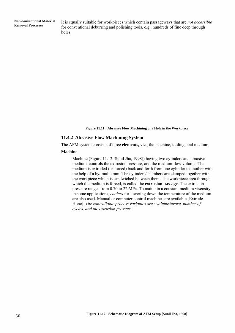
Figure 11.11 : Abrasive Flow Machining of a Hole in the Workpiece
11.4.2 Abrasive Flow Machining System The AFM system consists of three elements, viz., the machine, tooling, and medium. Machine
Machine (Figure 11.12 [Sunil Jha, 1998]) having two cylinders and abrasive medium, controls the extrusion pressure, and the medium flow volume. The medium is extruded (or forced) back and forth from one cylinder to another with the help of a hydraulic ram. The cylinders/chambers are clamped together with the workpiece which is sandwiched between them. The workpiece area through which the medium is forced, is called the extrusion passage. The extrusion pressure ranges from 0.70 to 22 MPa. To maintain a constant medium viscosity, in some applications, coolers for lowering down the temperature of the medium are also used. Manual or computer control machines are available [Extrude Hone]. The controllable process variables are : volume/stroke, number of cycles, and the extrusion pressure.
Figure 11.12 : Schematic Diagram of AFM Setup [Sunil Jha, 1998]
31
Mechanical Advanced Machining Processes
Tooling
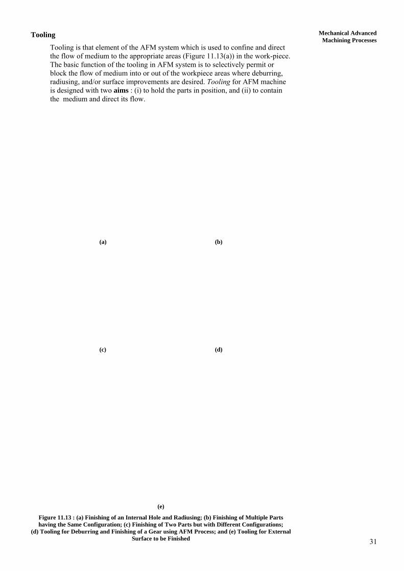
Tooling is that element of the AFM system which is used to confine and direct the flow of medium to the appropriate areas (Figure 11.13(a)) in the work-piece. The basic function of the tooling in AFM system is to selectively permit or block the flow of medium into or out of the workpiece areas where deburring, radiusing, and/or surface improvements are desired. Tooling for AFM machine is designed with two aims : (i) to hold the parts in position, and (ii) to contain the medium and direct its flow.
(a) (b)
(c) (d)
(e)
Figure 11.13 : (a) Finishing of an Internal Hole and Radiusing; (b) Finishing of Multiple Parts having the Same Configuration; (c) Finishing of Two Parts but with Different Configurations;
(d) Tooling for Deburring and Finishing of a Gear using AFM Process; and (e) Tooling for External Surface to be Finished
32
Non-conventional Material Removal Processes
Maximum material removal takes place wherever there is a maximum restriction to the flow of medium. While finishing internal surfaces like bore of a shaft, configuration of the bore itself decides the extent of restriction present to the flow of medium (Figures 11.13(a), 11.13(b) and 11.13(c)). In case of external surfaces, the tool designer decides the extent of restriction to be imposed (Figures 11.13(d) and 11.13(e)). In case of polishing of spur gear teeth, diameter of a cylinder placed around the gear teeth determines the extent of restriction present for the flow of medium (Figure 11.13(d)).
Passages of similar nature can be processed in parallel (Figure 11.13(b)). In case of a non-uniform cross-section, MRR at the narrowest section will be maximum and that of the widest section will be minimum (Figure 11.13(c)). Replaceable inserts made of nylon, teflon, or similar other materials are used for restricting the flow of medium to induce abrasive action. Once these inserts are worn out, they are replaced by new ones. Life of the inserts may be in terms of thousands of parts if they are properly designed.
Medium
Characteristics of the abrasive medium determine the aggressiveness of the action of abrasives during AFM process. AFM medium is pliable (easily molded) but is resilient enough to act as a self deforming grinding stone (Figure 11.14) when forced through a passageway [Rhoades, 1988]. It consists of the base material and abrasive grits. The base material (viscoplastic material) is made up of an organic polymer, and hydrocarbon gel. Composition of the base material determines its degree of stiffness. A stiff medium is used for large hole, while soft medium is used for small holes. High stiffness of the medium results in a kind of pure extrusion while soft medium will result into larger flow velocity in the center compared to that along the walls. It is reported that a stiff medium finishes a passageway more uniformly while a less stiff medium results in a greater radius at the passage opening [Williams, 1989]. When the abrasive medium comes in contact with the workpiece surface to be machined, the abrasive grains are held tightly in place and the medium acts as a self deformable grinding stone. Figure 11.14 shows the medium assuming different shapes depending upon the configuration of the workpiece to be finished. Hundreds of holes in a combustion liner of a gas turbine can be sized to a tolerance of hundredth of a millimeter. Types of abrasives used are Al2O3, SiC, cubic boron nitride (CBN) and diamond (written in the order of their increasing hardness and cost). These abrasives are available in different grit sizes. The abrasives have limited life. As a thumb rule, when the medium has machined an amount equal to 10% of its weight, it must be discarded. To assure a proper mixing of a new batch of medium (base material and abrasives), it should be cycled 20-50 times through a scrap part. Machined parts should be properly cleaned before use, by air or vacuum.
Figure 11.14 : Medium Acts as a Self-Deformable Stone
11.4.3 Process Variables Important factors that affect the process performance and the product quality (viz. accuracy, MRR, and surface integrity), are as discussed below :
(i) workpiece material (hardness and composition),
33
Mechanical Advanced Machining Processes
(ii) machine and tooling (fixture design, cylinder size, clamping pressure, etc.),
(iii) variable parameters (pressure, number of cycles, etc.),
(iv) geometry of the component(s) (passage shape, length to diameter ratio, length of flow path, etc.), and
(v) medium (viscosity and its change during the process, volume flow rate, and abrasive type, size, and concentration).
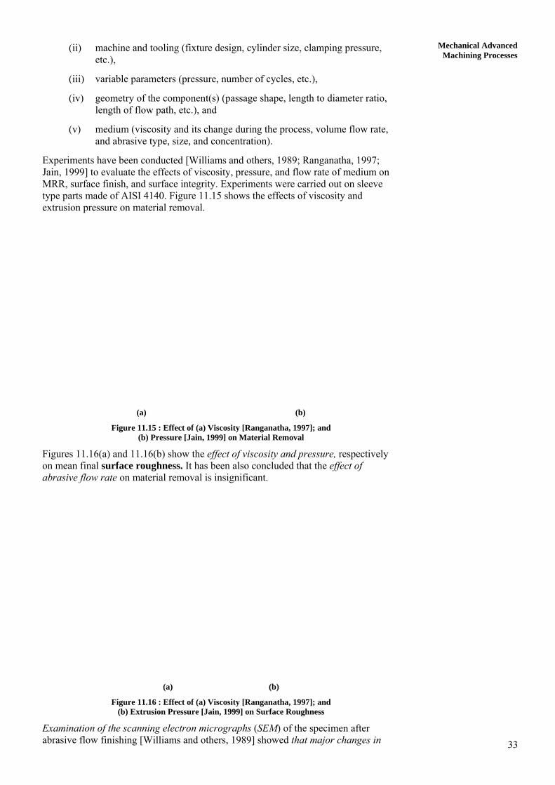
Experiments have been conducted [Williams and others, 1989; Ranganatha, 1997; Jain, 1999] to evaluate the effects of viscosity, pressure, and flow rate of medium on MRR, surface finish, and surface integrity. Experiments were carried out on sleeve type parts made of AISI 4140. Figure 11.15 shows the effects of viscosity and extrusion pressure on material removal.
(a) (b)
Figure 11.15 : Effect of (a) Viscosity [Ranganatha, 1997]; and (b) Pressure [Jain, 1999] on Material Removal
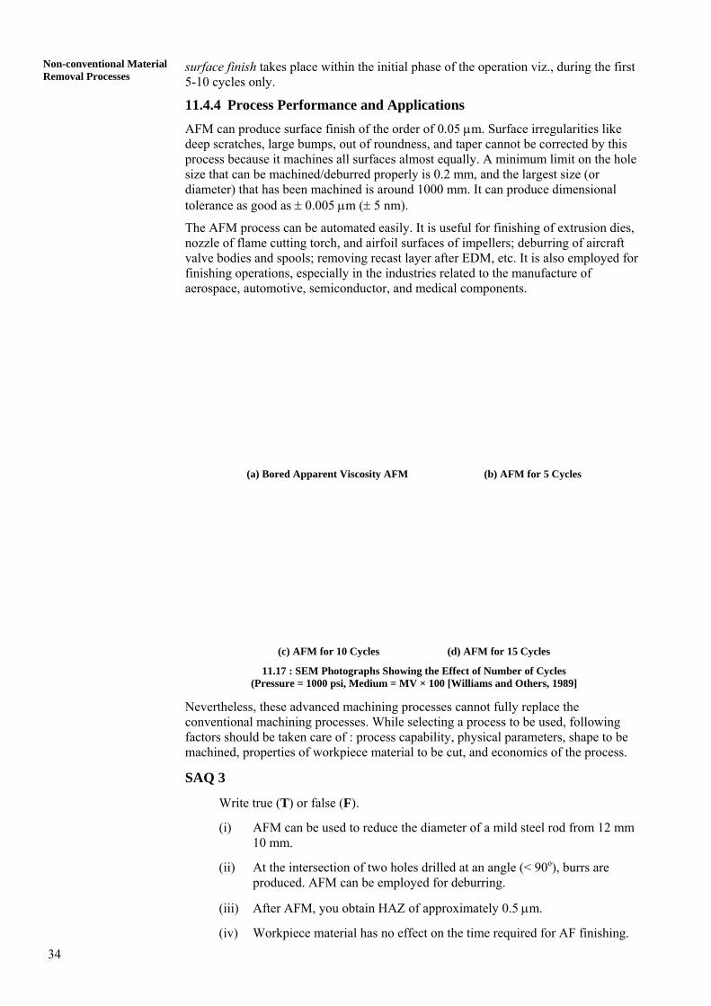
Figures 11.16(a) and 11.16(b) show the effect of viscosity and pressure, respectively on mean final surface roughness. It has been also concluded that the effect of abrasive flow rate on material removal is insignificant.
(a) (b)
Figure 11.16 : Effect of (a) Viscosity [Ranganatha, 1997]; and (b) Extrusion Pressure [Jain, 1999] on Surface Roughness
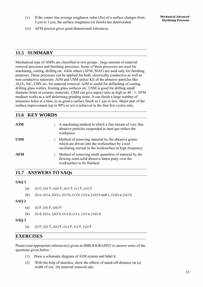
Examination of the scanning electron micrographs (SEM) of the specimen after abrasive flow finishing [Williams and others, 1989] showed that major changes in
34
Non-conventional Material Removal Processes
surface finish takes place within the initial phase of the operation viz., during the first 5-10 cycles only.
11.4.4 Process Performance and Applications AFM can produce surface finish of the order of 0.05 μm. Surface irregularities like deep scratches, large bumps, out of roundness, and taper cannot be corrected by this process because it machines all surfaces almost equally. A minimum limit on the hole size that can be machined/deburred properly is 0.2 mm, and the largest size (or diameter) that has been machined is around 1000 mm. It can produce dimensional tolerance as good as ± 0.005 μm (± 5 nm). The AFM process can be automated easily. It is useful for finishing of extrusion dies, nozzle of flame cutting torch, and airfoil surfaces of impellers; deburring of aircraft valve bodies and spools; removing recast layer after EDM, etc. It is also employed for finishing operations, especially in the industries related to the manufacture of aerospace, automotive, semiconductor, and medical components.
(a) Bored Apparent Viscosity AFM (b) AFM for 5 Cycles
(c) AFM for 10 Cycles (d) AFM for 15 Cycles
11.17 : SEM Photographs Showing the Effect of Number of Cycles (Pressure = 1000 psi, Medium = MV × 100 [Williams and Others, 1989]
Nevertheless, these advanced machining processes cannot fully replace the conventional machining processes. While selecting a process to be used, following factors should be taken care of : process capability, physical parameters, shape to be machined, properties of workpiece material to be cut, and economics of the process.
SAQ 3
Write true (T) or false (F).
(i) AFM can be used to reduce the diameter of a mild steel rod from 12 mm 10 mm.
(ii) At the intersection of two holes drilled at an angle (< 90o), burrs are produced. AFM can be employed for deburring.
(iii) After AFM, you obtain HAZ of approximately 0.5 μm.
(iv) Workpiece material has no effect on the time required for AF finishing.
35
Mechanical Advanced Machining Processes
(v) If the center line average roughness value (Ra) of a surface changes from 3 μm to 1 μm, the surface roughness (or finish) has deteriorated.
(vi) AFM process gives good dimensional tolerances.
11.5 SUMMARY
Mechanical type of AMPs are classified in two groups : large amount of material removal processes and finishing processes. Some of these processes are used for machining, cutting, drilling etc. while others (AFM, MAF) are used only for finishing purposes. These processes can be applied for both, electrically conductive as well as non-conductive materials. AJM and USM utilize KE of the abrasive particles like Al2O3, SiC, CBN etc. for material removal. AJM is useful for deflashing of casting, drilling glass wafers, frosting glass surfaces etc. USM is good for drilling small diameter holes in ceramic materials. USM can give aspect ratio as high as 40 : 1. AFM medium works as a self deforming grinding stone. It can finish a large number of miniature holes at a time, to as good a surface finish as 1 µm or less. Major part of the surface improvement (up to 90% or so) is achieved in the first few cycles only.
11.6 KEY WORDS
AJM : A machining method in which a fine stream of very fine abrasive particles suspended in inert gas strikes the workpiece.
USM : Method of removing material by the abrasive grains which are driven into the worksurface by a tool oscillating normal to the worksurface at high frequency.
AFM : Method of removing small quantities of material by the flowing semi-solid abrasive latten putty over the worksurface to be finished.
11.7 ANSWERS TO SAQs
SAQ 1
(a) (i) F, (ii) T, (iii) T, (iv) T, (v) T, (vi) F.
(b) (i) a, (ii) a, (iii) c, (iv) b, (v) b, (vi) a, (vii) b and c, (viii) a, (ix) b.
SAQ 2
(a) (i) F, (ii) F, (iii) F.
(b) (i) d, (ii) c, (iii) b, (iv) d, (v) c, (vi) a, (vii) d.
SAQ 3
(a) (i) F, (ii) T, (iii) F, (iv) F, (v) F, (vi) F.
EXERCISES
Please read appropriate reference(s) given in BIBLIOGRAPHY to answer some of the questions given below :
(1) Draw a schematic diagram of AJM system and label it.
(2) With the help of sketches, show the effects of stand-off-distance on (a) width of cut, (b) material removal rate.
36
Non-conventional Material Removal Processes
(3) Why abrasive jet machining process is not recommended to machine ductile materials?
(4) Draw a sketch showing the effect of carrier gas pressure on MRR during AJM.
(5) Name the parameters of AJM process.
(6) Write the applications of different types of abrasives used in AJM.
(7) Write functions of slurry, horn, transducer, and oscillator in USM.
(8) In table form, compare conventional grinding and USM.
(9) Write properties of different types of abrasives used in USM.
(10) Write working principle of piezoelectric transducers used in USM machine.
(11) Comment on the possible effects of use of audible frequency in USM.
(12) What do you understand by magnetostriction effects?
(13) Draw the relationship observed during USM for the following cases :
(a) frequency vs penetration rate;
(b) grain size vs machining rate;
(c) concentration vs machining rate;
(d) ratio of workpiece hardness to tool material hardness vs MRR.
(14) Write the four basic mechanisms by which material removal in USM can take place.
(15) USM is used for drilling a hole (under the same machining conditions) in aluminum and C.I. Which one will have higher depth of the drilled hole?
(16) A cylindrical impression of 10 mm diameter and 1 mm deep is to be made on a WC specimen. Feed force is constant, and is equal to 5 N. Average diameter of grains in the slurry is 10μm. Tool oscillates with the amplitude of 30 μm at 20 kHz. Abrasive and water ratio in the slurry is 1. Fracture hardness of WC workpiece may be taken as 7000 N/mm2 and that of copper tool as 1500 N/mm2. Calculate the time required to complete the job if only 20% of pulses are effective. Assume K1 = 0.3, K2 = 1.8 mm2, K3 = 0.6, and K1 = 1.8 mm2.
(17) Justify the statement : “AFM has high flexibility”.
(18) How the restriction offered by passageway in AFM governs MRR? Make necessary sketches.
(19) Explain the basic principle of tooling design for AFM process with the help of examples for internal as well as external surface finishing (take examples other than those given in this chapter).
(20) Write names of five such components which can be finished by AFM process but not by conventional processes.
(21) In which cases of the following, you will recommend the use of AFM process :
(a) A component has been machined by EDM process. It is found that extremely hard top layer (≈ 7 μm) has to be removed before it can be put to use.
(b) ECM'd component is found weak in fatigue strength. It is decided to remove a layer of material (≈ 1 × 10– 5 m) to improve its fatigue strength.
(c) During gear cutting, burrs are formed. Gears can be used only after removing these burrs.
37
Mechanical Advanced Machining Processes
(d) A cylinder has 50 small sized (0.6 mm diam.) holes to be finished. 20 such cylinders are to be finished every day.
(22) A hollow cylinder (inner diam. = 4 mm, outer diam. = 14 mm) requires improved surface finish on its outer and inner curved surfaces. Would you recommend AFM? Note that workpiece material is hardened steel and permissible dimensional change in its length is 20 μm. Draw the suggested tooling, if any.
(23) Comment on the reuse of abrasives in AFM process.
NOMENCLATURE
a/2 Amplitude of vibration
A Area
d (= 2R) Abrasive diameter
f Frequency of vibration of tool
F Force
h Crater height
htl Abrasive penetration depth in the tool
hw Abrasive penetration depth in the workpiece
hh htl + hw
j Ratio of hardness of workpiece material to the tool material
KE Kinetic Energy
K1, K2 Constants
K3 Probability of an abrasive particle under the tool being effective
m Mass of a grit
N Number of impacts on the workpiece by the grits in each cycle
r Crater radius
t Time
T Cycle time
ΔT Small time period
USM Ultrasonic machining
Vc Amount of material removed per cycle
Vs Volume of material removed per second
Vg Volume of material removed per grit per cycle
Vh Volumetric material removal rate from the workpiece due to hammering mechanism
Vth Volumetric material removal rate from the workpiece due to throwing mechanism
Wg Work done by the grit
Y Displacement of the tool
maxY& Maximum velocity of the tool
ρa Density of abrasive particles
σw Mean stress acting on the workpiece surface
σtl Mean stress acting on the tool surface

38
Non-conventional Material Removal Processes
Suffix
a abrasive
avg average
h hammering
max maximum
th throwing
tl tool
w workpiece
39
Mechanical Advanced Machining ProcessesBIBLIOGRAPHY
For Abrasive Jet Machining
Benedict, G. F. (1987), Non-traditional Manufacturing Processes, Marcel Dekker Inc., New York.
Bitter, J. G. A. (1962-63), A Study of Erosion Phenomenon-Part I, Wear, Vol. 5-6, p.5.
Butler, K. (Sept/ Oct 1980), Blast Your Problems Away, Tool Carbide, pp. 12-15.
Dombrowski, T. R. (Feb 1983), The How and Why of Abrasive Jet Machining, Modern Machine Shop, pp. 76-79.
Ingulli, C. N. (1967), Abrasive Jet Machining, Tool and Manuf. Engrs., Vol. 59, p. 28.
McGeough, J. A. (1988), Advanced Methods of Machining, Chapman and Hall, London, p. 211.
Pandey, P.C. and Shan, H. S. (1980), Modern Machining Processes, Tata McGraw Hill Publishing Co. Ltd., New Delhi, p. 39.
Sarkar, P. K. and Pandey, P.C. (1976), Some Investigations in Abrasive Jet Machining, J. Inst. of Engrs (I), Vol. 56, Pt. ME-5, p. 284.
Sheldon, G. L. and Finnie, I. (1966), The Mechanics of Material Removal in the Erosive Cutting of Brittle Materials, Trans ASME, Sr. B, Vol. 88, p. 393.
Verma, A. P. and Lal, G. K. (1985), Basic Mechanics of Abrasive Jet Machining, The Institution of Engineers (I), Production Engg. Div., Vol. 66, pp. 74-81.
Verma, A. P. and Lal, G. K. (1984), An Experimental Study of Abrasive Jet Machining, Int. J. Mach. Tool Des. Res., Vol. 24, No. 1, pp. 19-29.
For Ultrasonic Machining
Bellows, G. and Kohls, J. B. (1982), Drilling Without Drills, American Special Report, 743, p. 187.
Benedict, G. F. (1987), Nontraditional Manufacturing Processes, Marcel Dekker Inc., New York.
Bhattacharyya, A. (1973), New Technology, The Institution of Engineers (I), Calcutta.
Kainth, G. S. Nandy, A. and Singh, K. (1979), On the Mechanics of Material Removal in Ultrasonic Machining, Int. J. Mach. Tool Des. and Res., Vol. 19, pp. 33-41.
Kennedy, D. C. and Grieve, R. J. (Sept. 1975), Ultrasonic Machining A Review, The Production Engineer, Vol. 54, pp. 481-486.
Kremer, D. et al (1981), The State of the Art of Ultrasonic Machining, Annals of the CIRP, Vol. 30(1), pp. 107-110.
Markov, A. I. et al (1977), Ultrasonic Drilling and Milling of Hard Non Metallic Materials with Diamond Tools, Machines and Tooling, Vol. 48(9), pp. 33-35.
McGeough, J. A. (1988), Advanced Methods of Machining, Chapman & Hall, London.
Miller, G. E. (1957), Special Theory of Ultrasonic Machining, J. Applied Physics, No. 2, Vol. 28, p. 149.
40
Non-conventional Material Removal Processes
Pandey, P. C. and Shan, H. S. (1980), Modern Machining Processes, Tata McGraw Hill, New Delhi.
Shaw, M. C. (1956), Ultrasonic Grinding, Microtecnic, Vol. 10, p.257.
Soundararajan, V. and Radhakrishnan, V. (1986), An Experimental Investigation on the Basic Mechanism Involved in Ultrasonic Machining, Int. J. Mach. Tool Des. and Res., Vol. 26(3), pp. 307-332.
For Abrasive Flow Machining
Benedict, G. F. (1987), Nontraditional Manufacturing Processes, Marcel Dekker Inc., New York, pp. 53-65. Extrude Hone Technical Pamphlet U.S.A.
Jain, V. K. (2002), Advanced Machining Processes, Allied Publishers.
Jain, R. K., (1999), Modeling and Simulation of Abrasive Flow Process, Ph. D. Thesis, I.I.T., Kanpur, India.
Jha, Sunil (1998), On the Abrasive Flow Machining Process Performance, M. Tech. Thesis, I.I.T., Kanpur, India.
Kohut, T. (1984), Automatic Die Polishing, Extrusion Productivity Through Automation, Washington D. C., The Aluminium Association, Vol. 1, pp. 193-202.
Kohut, T. (1988), Surface Finishing with Abrasive Flow Machining Proc. 4th Int. Aluminium Extrusion Technology Seminar, Washington D. C., The Aluminium Association, Vol. 2.
Przyklen, K. (1986), Abrasive Flow Machining - A Process for Surface Finishing and Deburring of Workpieces with a Complicated Shape by Means of Abrasive Laden Medium, Advances in Nontraditional Machining PED, Vol. 22, Ed.: Rajurkar K. P., ASME, New York, pp. 101-110.
Pandit, S. M., and Sathyanarayanan, G. (1981), A New Approach to the Analysis of Wheel Workpiece Interaction in Surface Grinding, Proc. 9th North American Manufacturing Research Conference, pp. 311-320.
Pandit, S. M. and Wu, S. M. (1983), Time Series and System Analysis with Applications, John Wiley, New York.
Ranganatha, C. (1997), On the Evaluation of Rheological Properties of Media used in Abrasive Flow Machining, M. Tech. Thesis, I.I.T., Kanpur, India.
Rhoades, L. J. (1988), Abrasive Flow Machining, Manufacturing Engineering, pp. 75-78.
Sathyanarayanan, G. and Pandit, S. M. (1985), Fracture and Attritious Wear Rates in Grinding by Data Dependent System, Proc. 13th North American Manufacturing Research Conference, pp. 314 -320.
Williams, R. E. (1989), Metal Removal and Surface Finish Characteristics in Abrasive Flow Machining, M S Thesis, University of Nebraska at Lincoln, Nebraska, USA.
Williams, R. E. and Rajurkar, K. P. (1989), Mechanics of Deburring and Surface Finishing Processes, Presented at Winter Annual Meeting of ASME, held at San Francisco, Dec. 10-15, 1989, PED, Vol. 38, pp. 93-106.
Williams, R. E., Rajurkar, K. P. and Rhoades, L. J. (1989), Performance Characteristics of Abrasive Flow Machining, SME Technical Paper, FC 8980-610 to F8980-616.
Williams, R. E. and Rajurkar, K. P. (1992), Stochastic Modeling and Analysis of Abrasive Flow Machining, Trans ASME, J. of Engg. for Industry, Vol. 114, pp. 74-80.