Embed Size (px)
Citation preview
Freescale Semiconductor, Inc.Application Note
© 2010, 2013, 2015 Freescale Semiconductor, Inc. All rights reserved.
1 IntroductionThis application note describes the low-level blocks of the power management unit (PMU). This includes the basic power-supply and power-rail configurations and how to use the Linux BSP to configure the PMU on the i.MX28 processor for different applications. The application note also describes the battery charger block and power savings features of the i.MX28 processor.
2 i.MX28 power subsystemThis section provides an overview of the i.MX28 power subsystem, along with detailed information on power sources, power supply, power rails, and the battery charger.
2.1 i.Mx28 power subsystem—overview
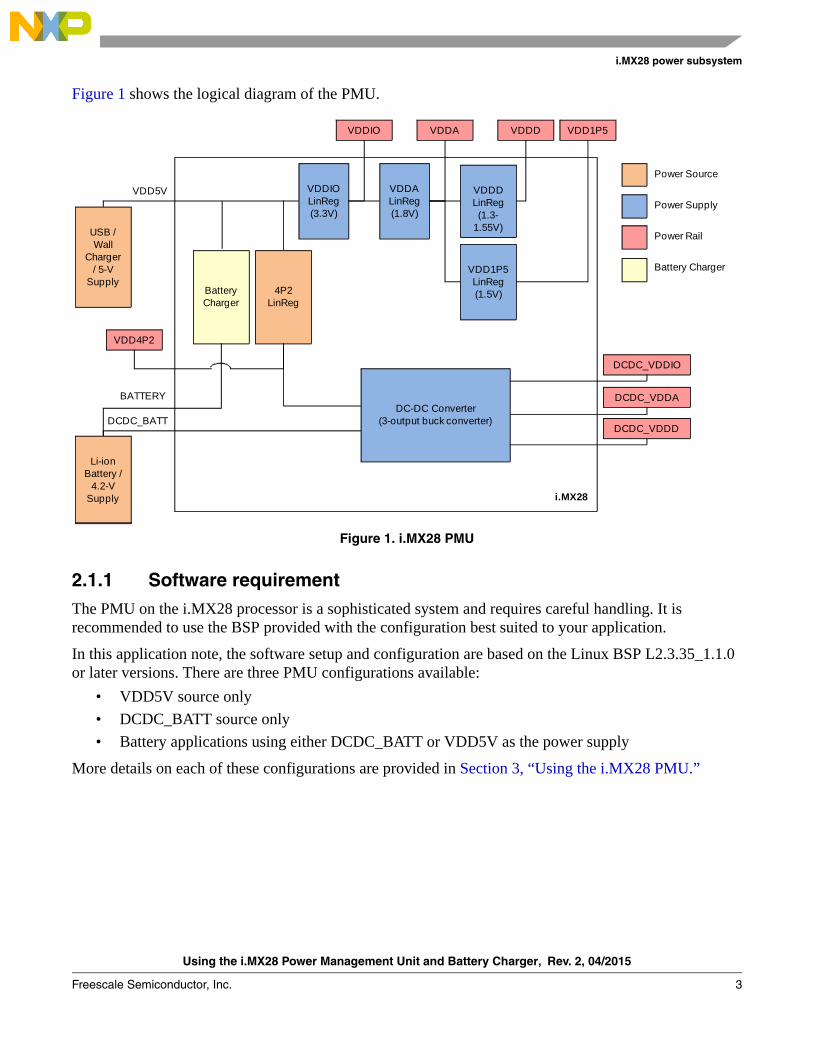
The i.MX28 application processor integrates a highly efficient and comprehensive power supply. This power supply is powered by the DCDC_BATT or VDD5V power source to generate five internal power rails.
Document Number: AN4199Rev. 2, 04/2015
Contents1. Introduction . . . . . . . . . . . . . . . . . . . . . . . . . . . . . . . . . 12. i.MX28 power subsystem . . . . . . . . . . . . . . . . . . . . . . 13. Using the i.MX28 PMU . . . . . . . . . . . . . . . . . . . . . . 174. Thermal overload protection . . . . . . . . . . . . . . . . . . . 265. Conclusion . . . . . . . . . . . . . . . . . . . . . . . . . . . . . . . . 276. References . . . . . . . . . . . . . . . . . . . . . . . . . . . . . . . . . 277. Revision history . . . . . . . . . . . . . . . . . . . . . . . . . . . . 27
Using the i.MX28 Power Management Unit and Battery ChargerGetting Started with Power Supply
Using the i.MX28 Power Management Unit and Battery Charger, Rev. 2, 04/2015
2 Freescale Semiconductor, Inc.
i.MX28 power subsystem
The hardware in the PMU is configured through firmware. The i.MX28 processor requires direct access to the registers in the power block. Though this increases the system complexity, it provides firmware the ability to optimize the PMU for different applications.
NOTEThe information provided in this application note is intended to supplement the information in the i.MX28 Applications Processor Reference Manual (MCIMX28RM).
The abbreviated form of the register names and bit fields that are frequently referred in this application note are given in Table 1.
The PMU consists of the following parts:
• Power sources—provide power to the internal power supplies
• Power supplies—convert the input sources to the voltage levels for the power rails of the i.MX28 processor
• Power rails—fed with the supply outputs
• Battery charger—activated by a 5-V supply that charges the attached Li-ion battery. The architecture of the i.MX28 processor allows the battery to be fully charged while powering devices through a separate power supply.
Table 1. Glossary
Term Definitions
DC-DC The only internal DC-DC switching converter in the i.MX28 processor. This is sometimes referred to as DCDC (without the hyphen) in the register names and bit fields.
LinReg Common abbreviation used for the linear regulator.
4P2 Alternate name for the 4.2-V rail. Here, P is the abbreviation used for “point” while referring to the rail in the data sheet or software.
Using the i.MX28 Power Management Unit and Battery Charger, Rev. 2, 04/2015
Freescale Semiconductor, Inc. 3
i.MX28 power subsystem
Figure 1 shows the logical diagram of the PMU.
Figure 1. i.MX28 PMU
2.1.1 Software requirementThe PMU on the i.MX28 processor is a sophisticated system and requires careful handling. It is recommended to use the BSP provided with the configuration best suited to your application.
In this application note, the software setup and configuration are based on the Linux BSP L2.3.35_1.1.0 or later versions. There are three PMU configurations available:
• VDD5V source only
• DCDC_BATT source only
• Battery applications using either DCDC_BATT or VDD5V as the power supply
More details on each of these configurations are provided in Section 3, “Using the i.MX28 PMU.”
Battery Charger
4P2LinReg
USB / Wall
Charger / 5-V
Supply
Li-ion Battery /
4.2-V Supply
BATTERY
DCDC_BATTDC-DC Converter
(3-output buck converter)
VDDIO LinReg(3.3V)
VDDA LinReg(1.8V)
VDD1P5 LinReg(1.5V)
VDDD LinReg(1.3-
1.55V)
VDD4P2
VDDIO VDDA VDDD VDD1P5
DCDC_VDDD
DCDC_VDDA
DCDC_VDDIO
i.MX28
VDD5V
Power Source
Power Supply
Power Rail
Battery Charger
Using the i.MX28 Power Management Unit and Battery Charger, Rev. 2, 04/2015
4 Freescale Semiconductor, Inc.
i.MX28 power subsystem
2.1.2 Hardware requirementThe i.MX28 processor is highly integrated and requires a few external components. The i.MX28 Reference Schematics are available at www.freescale.com/webapp/sps/site/prod_summary.jsp?code=i.MX280&nodeId=018rH3ZrDRA24A&fpsp=1&tab=Design_Tools_Tab .
2.1.2.1 Inductor
An inductor is required for the DC-DC switching converter. The size of the inductor depends on the application and product specifications. For more information, see the i.MX28 Reference Schematics.
2.1.2.2 Capacitor
Capacitors are used for the PMU. Each power rail requires a capacitor of at least 33 F for decoupling in addition to the capacitors of 0.01 F, 0.1 F, and 1 F. Additionally, the 4P2 rail, battery, and VDD5V rail require capacitors ranging from 0.01 to 33 F. For the exact capacitor locations and sizes, see the i.MX28 Reference Schematics.
2.1.2.3 External power supply
The internal DC-DC converter can deliver an output power up to 1.2 W. For applications requiring high power, an external DC-DC converter or LDO is required to offload some of the power from the internal DC-DC converter. For more information, see the i.MX28 Reference Schematics.
2.2 Power sourcesThe i.MX28 processor can be powered from the following sources:
• DCDC_BATT—Input to the DC-DC switching converter. The voltage should be in the range of 3.3–4.2 V. This input can be powered by a Li-ion battery or regulated output from 3.3–4.2 V. It is highly recommended as a power source for industrial applications, because it has no input current limit.
• VDD5V—Input to the internal LinRegs. It can also be used to source the internal DC-DC with the 4.2 V regulated by the 4P2 LinReg. The 5-V source can be taken from a universal serial bus (USB) connection, a wall charger with 5-V output, or a 5-V regulated from a supply with higher voltage. There is a 100-mA input current limit when the system is powering up from the Power-Off state. Product designers should pay attention to ensure the 100 mA is sufficient for the total system consumption during cold-boot or reboot.
The power sources do not have to be operated simultaneously. The PMU uses the VDD5V supply for powering the internal 4P2 power source to generate the 4P2 rail. This 4P2 rail is used as an input to the DC-DC converter.
The battery charger can also be considered as a power source. However, it provides power only to the battery and not directly to the system.
Using the i.MX28 Power Management Unit and Battery Charger, Rev. 2, 04/2015
Freescale Semiconductor, Inc. 5
i.MX28 power subsystem
2.2.1 DCDC_BATT sourcesThe DCDC_BATT source provides power directly to the DC-DC converter on the i.MX28 processor. The input voltage should be in the range of 3.3–4.2 V to provide a reliable power level to the system. The DC-DC converter starts to operate when applying an input supply to the source and PSWITCH is asserted. The DC-DC converter does not start when a supply is attached. It only starts when PSWITCH is asserted. The rails are then raised to their default values and the on-chip read-only-memory (ROM) begins to execute. The battery voltage monitor, which is configured by the firmware, should be set to alert the system when the voltage drops to a critically low level. This prevents brownouts and unexpected device shutdown.
2.2.2 VDD5V sourcesThe VDD5V source can take an input from a USB connection, a regulated 5-V source or a 5-V wall adaptor.
When a 5-V supply is detected on VDD5V, the internal LinRegs powers on the i.MX28 processor automatically. PSWITCH does not need to be asserted for the PMU to start. The power rails are then raised to their default values and the on-chip ROM begins to execute. After the i.MX28 processor is booted, the firmware enables the 4.2-V LinReg to supply the DC-DC converter instead of using the internal LinRegs to power the rails.
The 5-V removal detection is then set up by the firmware to alert the system when the supply on VDD5V is lost. The hardware is configured to switch automatically to the DCDC_BATT source if it is available. Otherwise, it is configured to power down the system when the 5-V supply is lost.
2.2.2.1 5-V detection methods
There are two 5V-detection mechanisms available in the i.MX28 processor: VBUSVALID and VDD5V_GT_VDDIO. Each method detects the 5-V voltage value differently.
VBUSVALID
The VBUSVALID detection method is an accurate 5-V detection mechanism in the i.MX28 processor. It is recommended to use this method during the normal operation. The VBUSVALID mechanism compares the VDD5V voltage with an internal bias voltage. The threshold value for a valid 5-V status is configured in the software, and the default value is 4.4 V on the Linux BSP. Additionally, the VBUSVALID method can be configured to generate an interrupt signal when the 5-V supply is removed or inserted.
VDD5V_GT_VDDIO
The VDD5V_GT_VDDIO detection method is the default method used at the device startup. This allows the PMU to determine the status of the VDD5V source before the internal bias and comparators are enabled. When the software gains control over the processor, the VBUSVALID method is initialized and used as the 5-V detection method.
The VDD5V_GT_VDDIO method compares VDD5V with the VDDIO voltage plus an offset. The offset is approximately 600 mV. This detection method works for the device on start-up. However, it is not recommended for normal operation, because it is not robust for detecting the removal of the 5-V supply. This is because the VDDIO LinReg is powered from the VDD5V rail, and during heavy loads on the
Using the i.MX28 Power Management Unit and Battery Charger, Rev. 2, 04/2015
6 Freescale Semiconductor, Inc.
i.MX28 power subsystem
VDDIO rail, the VDDIO voltage drops at the same rate as that of VDD5V. This delays the detection when the 5-V supply is removed.
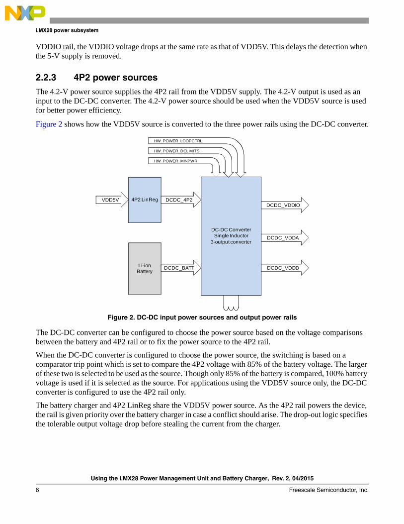
2.2.3 4P2 power sourcesThe 4.2-V power source supplies the 4P2 rail from the VDD5V supply. The 4.2-V output is used as an input to the DC-DC converter. The 4.2-V power source should be used when the VDD5V source is used for better power efficiency.
Figure 2 shows how the VDD5V source is converted to the three power rails using the DC-DC converter.
Figure 2. DC-DC input power sources and output power rails
The DC-DC converter can be configured to choose the power source based on the voltage comparisons between the battery and 4P2 rail or to fix the power source to the 4P2 rail.
When the DC-DC converter is configured to choose the power source, the switching is based on a comparator trip point which is set to compare the 4P2 voltage with 85% of the battery voltage. The larger of these two is selected to be used as the source. Though only 85% of the battery is compared, 100% battery voltage is used if it is selected as the source. For applications using the VDD5V source only, the DC-DC converter is configured to use the 4P2 rail only.
The battery charger and 4P2 LinReg share the VDD5V power source. As the 4P2 rail powers the device, the rail is given priority over the battery charger in case a conflict should arise. The drop-out logic specifies the tolerable output voltage drop before stealing the current from the charger.
VDD5V 4P2 LinReg
Li-ion Battery
DCDC_4P2
DCDC_BATT
DC-DC ConverterSingle Inductor
3-output converter
DCDC_VDDIO
DCDC_VDDA
DCDC_VDDD
HW_POWER_MINPWR
HW_POWER_DCLIMITS
HW_POWER_LOOPCTRL
Using the i.MX28 Power Management Unit and Battery Charger, Rev. 2, 04/2015
Freescale Semiconductor, Inc. 7
i.MX28 power subsystem
2.3 Power suppliesThe power supplies in the i.MX28 processor are as follows:
• Integrated single-inductor three-output DC-DC switching converter—This is the most power-efficient supply on the i.MX28 processor. It uses the input from DCDC_BATT or the internally generated 4P2 rail to supply power to the three output rails: VDDD, VDDA, and VDDIO.
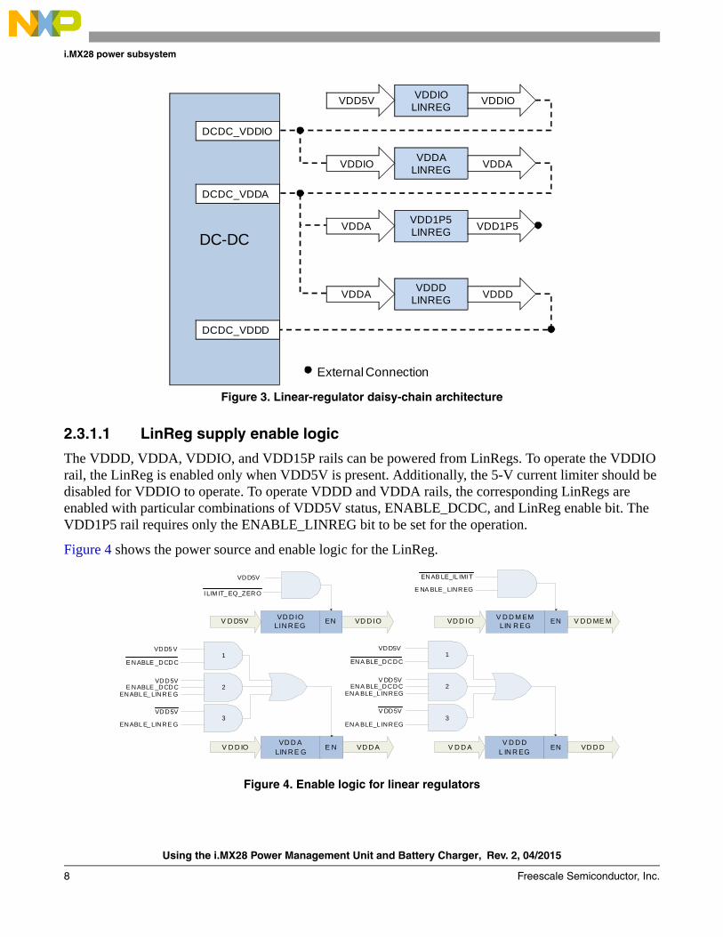
• Multiple LinRegs—Contains a group of LinRegs where each takes a single input and regulates the voltage to the target output level. The LinRegs are reliable and stable, but not as efficient as the DC-DC converter. The LinRegs for the power rails are in a daisy-chained architecture where the output voltage is available from higher to lower values. In cases where the input is an internal power rail, the LinReg can alternatively be powered from the DC-DC output of the rail. See Figure 3.
The 4.2-V LinReg uses the VDD5V source to provide 4.2 V to the DC-DC converter. This is called the 4P2 rail, and it takes the LinReg output to feed in the input of the DC-DC converter only from the 5-V supply. This allows the i.MX28 processor to use the more efficient DC-DC converter instead of the internal LinRegs when using the 5-V supply. The LinRegs are used to power the supply rails during boot-up when the 4.2-V LinReg is not initialized.
NOTEGenerally, the 4P2 LinReg is referred to as both an internal power source for the i.MX28 processor, and as the 4P2 power rail, because it is fed with the LinReg output.
2.3.1 LinReg power supplyThe LinReg power supply follows a linear-regulator daisy-chain architecture (see Figure 3). The VDDIO LinReg receives power from the VDD5V source, VDDA receives power from VDDIO, and VDDD receives power from VDDA, in turn. The VDD1P5 rail also receives power from VDDA. Because the DC-DC converter powers the VDDIO, VDDA, and VDDD rails, the DC-DC converter can also be the power source for the LinRegs.
Using the i.MX28 Power Management Unit and Battery Charger, Rev. 2, 04/2015
8 Freescale Semiconductor, Inc.
i.MX28 power subsystem
Figure 3. Linear-regulator daisy-chain architecture
2.3.1.1 LinReg supply enable logic
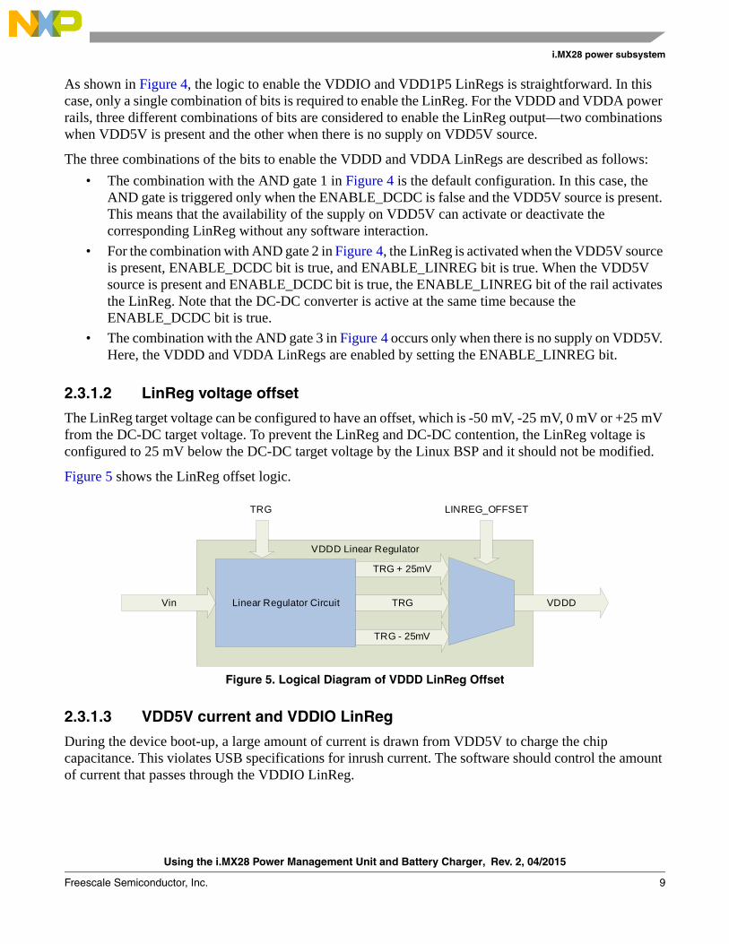
The VDDD, VDDA, VDDIO, and VDD15P rails can be powered from LinRegs. To operate the VDDIO rail, the LinReg is enabled only when VDD5V is present. Additionally, the 5-V current limiter should be disabled for VDDIO to operate. To operate VDDD and VDDA rails, the corresponding LinRegs are enabled with particular combinations of VDD5V status, ENABLE_DCDC, and LinReg enable bit. The VDD1P5 rail requires only the ENABLE_LINREG bit to be set for the operation.
Figure 4 shows the power source and enable logic for the LinReg.
Figure 4. Enable logic for linear regulators
DC-DC
DCDC_VDDIO
DCDC_VDDA
DCDC_VDDD
VDDIO LINREG
VDD5V VDDIO
VDDA LINREG
VDDIO VDDA
VDDD LINREG
VDDA VDDD
VDD1P5 LINREG
VDDA VDD1P5
External Connection
V D D ME MV D D M EM LIN R EG
ENVD D IO
VD D AVD D A
LIN R E GE NV D D IO VD D D
V D D D L IN R EG
ENV D D A
VD D IOVD D IO LIN R EG
ENV D D5V
VDD5V
I LIM IT_ EQ_ZERO
V DD5V2ENA BLE_DCDC
ENA BLE_L INREG
V DD5V3
ENA BLE_L INREG
ENAB LE_IL IMI T
E NA BLE_ LINREG
1VDD5V
ENA BLE_DCDC
VDD5V2E NABLE _DCDC
ENABL E_ LINRE G
VDD5V3
ENABL E_ LINRE G
1VDD5 V
E NABLE _DCDC
Using the i.MX28 Power Management Unit and Battery Charger, Rev. 2, 04/2015
Freescale Semiconductor, Inc. 9
i.MX28 power subsystem
As shown in Figure 4, the logic to enable the VDDIO and VDD1P5 LinRegs is straightforward. In this case, only a single combination of bits is required to enable the LinReg. For the VDDD and VDDA power rails, three different combinations of bits are considered to enable the LinReg output—two combinations when VDD5V is present and the other when there is no supply on VDD5V source.
The three combinations of the bits to enable the VDDD and VDDA LinRegs are described as follows:
• The combination with the AND gate 1 in Figure 4 is the default configuration. In this case, the AND gate is triggered only when the ENABLE_DCDC is false and the VDD5V source is present. This means that the availability of the supply on VDD5V can activate or deactivate the corresponding LinReg without any software interaction.
• For the combination with AND gate 2 in Figure 4, the LinReg is activated when the VDD5V source is present, ENABLE_DCDC bit is true, and ENABLE_LINREG bit is true. When the VDD5V source is present and ENABLE_DCDC bit is true, the ENABLE_LINREG bit of the rail activates the LinReg. Note that the DC-DC converter is active at the same time because the ENABLE_DCDC bit is true.
• The combination with the AND gate 3 in Figure 4 occurs only when there is no supply on VDD5V. Here, the VDDD and VDDA LinRegs are enabled by setting the ENABLE_LINREG bit.
2.3.1.2 LinReg voltage offset
The LinReg target voltage can be configured to have an offset, which is -50 mV, -25 mV, 0 mV or +25 mV from the DC-DC target voltage. To prevent the LinReg and DC-DC contention, the LinReg voltage is configured to 25 mV below the DC-DC target voltage by the Linux BSP and it should not be modified.
Figure 5 shows the LinReg offset logic.
Figure 5. Logical Diagram of VDDD LinReg Offset
2.3.1.3 VDD5V current and VDDIO LinReg
During the device boot-up, a large amount of current is drawn from VDD5V to charge the chip capacitance. This violates USB specifications for inrush current. The software should control the amount of current that passes through the VDDIO LinReg.
VDDD Linear Regulator
Linear Regulator Circuit
TRG + 25mV
TRG
TRG - 25mV
VDDDVin
LINREG_OFFSETTRG
Using the i.MX28 Power Management Unit and Battery Charger, Rev. 2, 04/2015
10 Freescale Semiconductor, Inc.
i.MX28 power subsystem
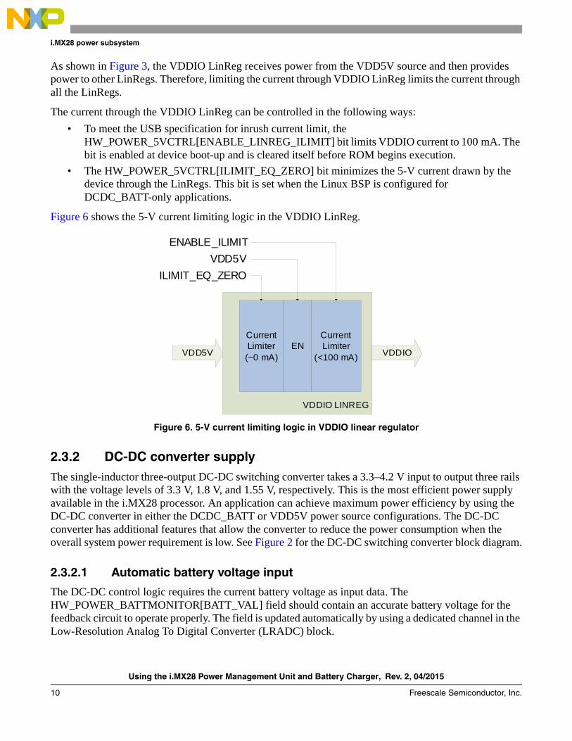
As shown in Figure 3, the VDDIO LinReg receives power from the VDD5V source and then provides power to other LinRegs. Therefore, limiting the current through VDDIO LinReg limits the current through all the LinRegs.
The current through the VDDIO LinReg can be controlled in the following ways:
• To meet the USB specification for inrush current limit, the HW_POWER_5VCTRL[ENABLE_LINREG_ILIMIT] bit limits VDDIO current to 100 mA. The bit is enabled at device boot-up and is cleared itself before ROM begins execution.
• The HW_POWER_5VCTRL[ILIMIT_EQ_ZERO] bit minimizes the 5-V current drawn by the device through the LinRegs. This bit is set when the Linux BSP is configured for DCDC_BATT-only applications.
Figure 6 shows the 5-V current limiting logic in the VDDIO LinReg.
Figure 6. 5-V current limiting logic in VDDIO linear regulator
2.3.2 DC-DC converter supplyThe single-inductor three-output DC-DC switching converter takes a 3.3–4.2 V input to output three rails with the voltage levels of 3.3 V, 1.8 V, and 1.55 V, respectively. This is the most efficient power supply available in the i.MX28 processor. An application can achieve maximum power efficiency by using the DC-DC converter in either the DCDC_BATT or VDD5V power source configurations. The DC-DC converter has additional features that allow the converter to reduce the power consumption when the overall system power requirement is low. See Figure 2 for the DC-DC switching converter block diagram.
2.3.2.1 Automatic battery voltage input
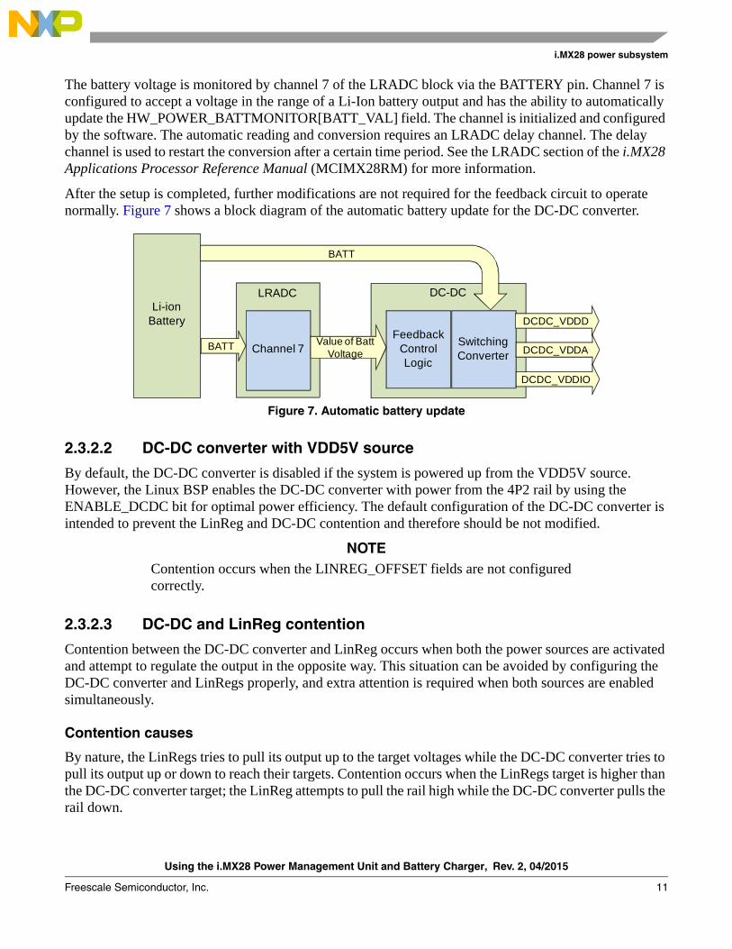
The DC-DC control logic requires the current battery voltage as input data. The HW_POWER_BATTMONITOR[BATT_VAL] field should contain an accurate battery voltage for the feedback circuit to operate properly. The field is updated automatically by using a dedicated channel in the Low-Resolution Analog To Digital Converter (LRADC) block.
VDDIO LINREG
VDDIOEN
VDD5V
VDD5V
Current Limiter
(<100 mA)
ENABLE_ILIMIT
Current Limiter (~0 mA)
ILIMIT_EQ_ZERO
Using the i.MX28 Power Management Unit and Battery Charger, Rev. 2, 04/2015
Freescale Semiconductor, Inc. 11
i.MX28 power subsystem
The battery voltage is monitored by channel 7 of the LRADC block via the BATTERY pin. Channel 7 is configured to accept a voltage in the range of a Li-Ion battery output and has the ability to automatically update the HW_POWER_BATTMONITOR[BATT_VAL] field. The channel is initialized and configured by the software. The automatic reading and conversion requires an LRADC delay channel. The delay channel is used to restart the conversion after a certain time period. See the LRADC section of the i.MX28 Applications Processor Reference Manual (MCIMX28RM) for more information.
After the setup is completed, further modifications are not required for the feedback circuit to operate normally. Figure 7 shows a block diagram of the automatic battery update for the DC-DC converter.
Figure 7. Automatic battery update
2.3.2.2 DC-DC converter with VDD5V source
By default, the DC-DC converter is disabled if the system is powered up from the VDD5V source. However, the Linux BSP enables the DC-DC converter with power from the 4P2 rail by using the ENABLE_DCDC bit for optimal power efficiency. The default configuration of the DC-DC converter is intended to prevent the LinReg and DC-DC contention and therefore should be not modified.
NOTEContention occurs when the LINREG_OFFSET fields are not configured correctly.
2.3.2.3 DC-DC and LinReg contention
Contention between the DC-DC converter and LinReg occurs when both the power sources are activated and attempt to regulate the output in the opposite way. This situation can be avoided by configuring the DC-DC converter and LinRegs properly, and extra attention is required when both sources are enabled simultaneously.
Contention causes
By nature, the LinRegs tries to pull its output up to the target voltages while the DC-DC converter tries to pull its output up or down to reach their targets. Contention occurs when the LinRegs target is higher than the DC-DC converter target; the LinReg attempts to pull the rail high while the DC-DC converter pulls the rail down.
Li-ion Battery
LRADC
Channel 7
DC-DC
FeedbackControlLogic
Switching Converter
BATT Value of BattVoltage
BATT
DCDC_VDDD
DCDC_VDDA
DCDC_VDDIO
Using the i.MX28 Power Management Unit and Battery Charger, Rev. 2, 04/2015
12 Freescale Semiconductor, Inc.
i.MX28 power subsystem
Contention effects
The effects of contention are as follows:
• The DC-DC converter pulls a high amount of current that leads to dips in the power source
• The current from VDD5V exceeds the USB specifications
• High current flow causes the processor to heat up, which raises the device temperature
Contention prevention
To prevent contention, the LinReg target output should be less than the DC-DC target output. In this case, the LinReg is satisfied when the output voltage is above the target voltage and does not further try to pull the output up. At the same time, the DC-DC converter does not try to pull the output down, because the output is at the target voltage. This configuration is set in the hardware through the LINREG_OFFSET bit. For each main power rail—VDDD, VDDA, and VDDIO—the Linux BSP sets the LINREG_OFFSET bit to 25 mV below the target voltage, and it should not be changed in any case.
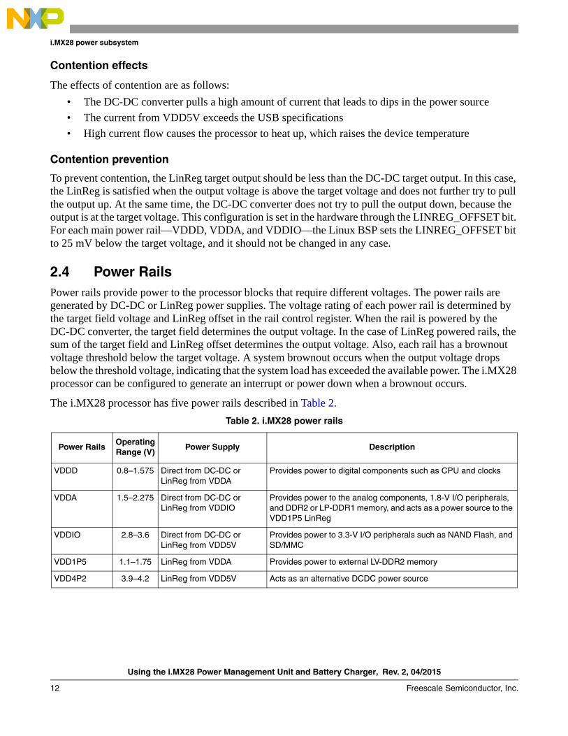
2.4 Power RailsPower rails provide power to the processor blocks that require different voltages. The power rails are generated by DC-DC or LinReg power supplies. The voltage rating of each power rail is determined by the target field voltage and LinReg offset in the rail control register. When the rail is powered by the DC-DC converter, the target field determines the output voltage. In the case of LinReg powered rails, the sum of the target field and LinReg offset determines the output voltage. Also, each rail has a brownout voltage threshold below the target voltage. A system brownout occurs when the output voltage drops below the threshold voltage, indicating that the system load has exceeded the available power. The i.MX28 processor can be configured to generate an interrupt or power down when a brownout occurs.
The i.MX28 processor has five power rails described in Table 2.
Table 2. i.MX28 power rails
Power RailsOperatingRange (V)
Power Supply Description
VDDD 0.8–1.575 Direct from DC-DC orLinReg from VDDA
Provides power to digital components such as CPU and clocks
VDDA 1.5–2.275 Direct from DC-DC orLinReg from VDDIO
Provides power to the analog components, 1.8-V I/O peripherals, and DDR2 or LP-DDR1 memory, and acts as a power source to the VDD1P5 LinReg
VDDIO 2.8–3.6 Direct from DC-DC orLinReg from VDD5V
Provides power to 3.3-V I/O peripherals such as NAND Flash, and SD/MMC
VDD1P5 1.1–1.75 LinReg from VDDA Provides power to external LV-DDR2 memory
VDD4P2 3.9–4.2 LinReg from VDD5V Acts as an alternative DCDC power source
Using the i.MX28 Power Management Unit and Battery Charger, Rev. 2, 04/2015
Freescale Semiconductor, Inc. 13
i.MX28 power subsystem
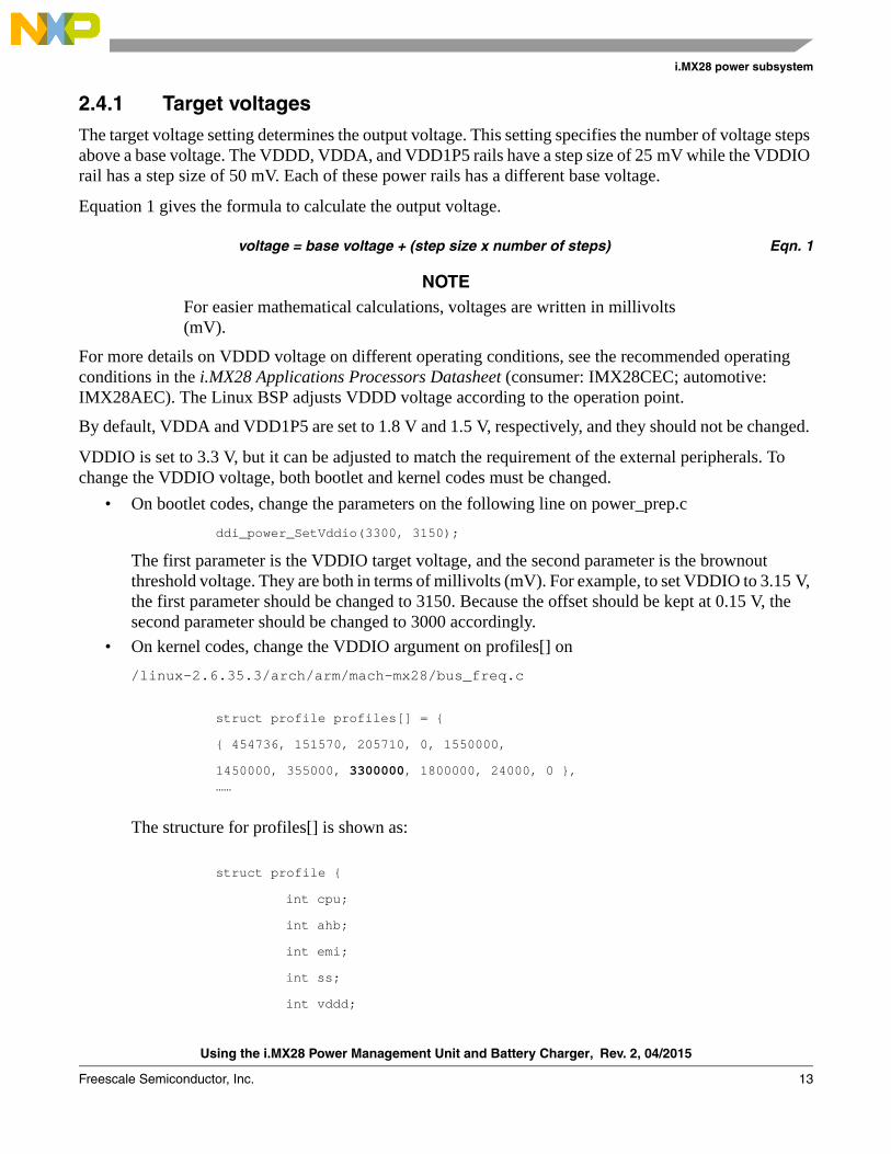
2.4.1 Target voltagesThe target voltage setting determines the output voltage. This setting specifies the number of voltage steps above a base voltage. The VDDD, VDDA, and VDD1P5 rails have a step size of 25 mV while the VDDIO rail has a step size of 50 mV. Each of these power rails has a different base voltage.
Equation 1 gives the formula to calculate the output voltage.
voltage = base voltage + (step size x number of steps) Eqn. 1
NOTEFor easier mathematical calculations, voltages are written in millivolts (mV).
For more details on VDDD voltage on different operating conditions, see the recommended operating conditions in the i.MX28 Applications Processors Datasheet (consumer: IMX28CEC; automotive: IMX28AEC). The Linux BSP adjusts VDDD voltage according to the operation point.
By default, VDDA and VDD1P5 are set to 1.8 V and 1.5 V, respectively, and they should not be changed.
VDDIO is set to 3.3 V, but it can be adjusted to match the requirement of the external peripherals. To change the VDDIO voltage, both bootlet and kernel codes must be changed.
• On bootlet codes, change the parameters on the following line on power_prep.c
ddi_power_SetVddio(3300, 3150);
The first parameter is the VDDIO target voltage, and the second parameter is the brownout threshold voltage. They are both in terms of millivolts (mV). For example, to set VDDIO to 3.15 V, the first parameter should be changed to 3150. Because the offset should be kept at 0.15 V, the second parameter should be changed to 3000 accordingly.
• On kernel codes, change the VDDIO argument on profiles[] on
/linux-2.6.35.3/arch/arm/mach-mx28/bus_freq.c
struct profile profiles[] = {
{ 454736, 151570, 205710, 0, 1550000,
1450000, 355000, 3300000, 1800000, 24000, 0 },……
The structure for profiles[] is shown as:
struct profile {
int cpu;
int ahb;
int emi;
int ss;
int vddd;

Using the i.MX28 Power Management Unit and Battery Charger, Rev. 2, 04/2015
14 Freescale Semiconductor, Inc.
i.MX28 power subsystem
int vddd_bo;
int cur;
int vddio;
int vdda;
u16 xbus;
/* map of the upper 16 bits of HW_CLKCTRL_HBUS register */
u16 h_autoslow_flags;
};
Only the argument vddio can be modified. The voltage here is in terms of V. Additionally, the VDDIO value here should be set to the same as that on the bootlet codes. As in the example above, the parameter should be changed from 3300000 to 3150000 in order to set VDDIO to 3.15 V. Other parameters control the voltage on other rails and should not be modified.
2.4.2 BrownoutsBrownouts occur when the voltage on a rail drops below the target voltage setting. Brownouts can be caused by excessive loads or insufficient input power. The i.MX28 PMU uses the brownout detectors that allow software or hardware to handle the brownouts. The software is notified of a brownout condition via interrupt so it can act accordingly. The hardware automatically shuts down the device when a brownout condition is detected.
2.4.2.1 Brownout thresholds
Brownout thresholds determine how much drop in voltage on a power rail would trigger a brownout. The threshold value is set in a register field that resides in one of the control registers. However, the calculation of the actual value to the written value varies with the type of brownout.
Power-rail brownout
The power-rail brownout threshold is an offset or margin from the target voltage register field. The actual value of the brownout threshold is the target output voltage minus the brownout voltage margin. The available range for the brownout offset is 0-175 mV in 25-mV steps for the VDDD, VDDA, VDDIO, and VDD1P5 power rails. On the Linux BSP, the brownout threshold is 100 mV for VDDD and VDD1P5, and the brownout threshold is 150 mV for VDDA and VDDIO. It is not recommended to change the brownout threshold.
Battery brownout
The battery brownout threshold is an absolute voltage level, unlike the power-rail brownout threshold, which is an offset value. The available range for the battery brownout threshold is 2.4–3.64 V with a 40-mV resolution. The battery brownout is triggered when the battery voltage drops below the threshold value and generates an interrupt notifying the application that the battery is low, and thus the system can be shut down gracefully. The minimum operating voltage with DCDC_BATT source is 3.3 V; therefore, the battery brownout voltage is set to 3.2 V by default. In cases that use a regulated supply with
Using the i.MX28 Power Management Unit and Battery Charger, Rev. 2, 04/2015
Freescale Semiconductor, Inc. 15
i.MX28 power subsystem
DCDC_BATT source, the brownout level should be modified according to the supply voltage for DCDC_BATT. The brownout level can be changed by modifying the definition for BATTERY_BRWNOUT_BITFIELD_VALUE in power_prep.c in the bootlet code. It should be set to a value equal to NUM_STEPS based on the formula below.
The formula to calculate the battery brownout threshold is similar to the equation to set a power-rail target voltage and is given in Equation 2.
BO_VOLT = BASE_VOLT + (STEP_SIZE x NUM_STEPS) Eqn. 2
Calculate the number of steps required to reach the brownout level of 3.2 V (3200 mV): Applying the values in Equation 2,
3200 = 2400 + (40 x NUM_STEPS))
NUM_STEPS = 20
VDD5V Brownout
In the i.MX28 PMU, the VDD5V-source brownout is called VBUS droop brownout. The VDD5V-source brownout level is a voltage threshold and is an absolute voltage value as in the case of a battery brownout. There are four available settings for VBUS droop brownout:
• 4.3 V
• 4.4 V
• 4.5 V
• 4.7 V
Each setting has a 50-mV hysteresis to prevent chattering. It is set to 4.5 V in the Linux BSP. The VBUS droop brownout only generates an interrupt when the VDD5V source drops below the threshold. This is useful to determine if the load on the VDD5V source is great and allows the software to handle it.
4P2 Brownout
The brownout threshold range for the 4P2 rail is 3.6-4.375 V with a resolution of 25 mV. The 4P2 brownout occurs when the 4P2 voltage reaches the brownout level. The device is configured to generate an interrupt when the 4P2 source drops below the threshold level.
2.4.2.2 Automatic hardware shutdown on brownout
The i.MX28 processor can be configured to automatically power down the device when brownout occurs. The power rails, VDDD, VDDA, VDDIO, battery, and VDD5V sources have this feature, depending on the presence of the VDD5V source. Each of these five brownout detectors has an enable bit to control the power locally, which, in turn, is controlled by the master enable switch.
In cases where the VDD5V supply is present, it is possible only for the VDD5V brownout automatic shutdown to be triggered. In this case, automatic shutdown due to the power-rail (VDDD, VDDA, and VDDIO) and battery brownouts are disabled. However, it should be noted that the Linux BSP has set up the interrupt to handle the brownout for these rails, regardless of the availability of the VDD5V supply.
Using the i.MX28 Power Management Unit and Battery Charger, Rev. 2, 04/2015
16 Freescale Semiconductor, Inc.
i.MX28 power subsystem
Automatic VDD5V Brownout Shutdown
The automatic VDD5V brownout shutdown uses the VBUSVALID threshold instead of the VBUSDROOP threshold. The automatic hardware shutdown is not activated until the VDD5V voltage level rises above the VBUSVALID threshold if the device is powering up from the VDD5V source. This feature is enabled for applications configured for VDD5V source only. For applications with both VDD5V and DCDC_BATT supplies, this feature is enabled only on startup and is disabled when the handoff-to-battery is set.
Automatic Battery Brownout Shutdown
The automatic battery brownout shutdown uses the battery brownout threshold. The battery brownout shutdown is enabled on applications with DCDC_BATT source as the only supply.
Automatic Power-Rail Brownout Shutdown
The power rails—VDDD, VDDA, and VDDIO—have automatic shutdown functionality. The VDD1P5 rail is generated from the VDDA rail and any brownout on the VDD1P5 rail affects the VDDA rail. The automatic shutdown is enabled during the device boot-up before the software interrupt handling is enabled. After boot-up, the automatic brownout shutdown is disabled and handled by software via interrupt.
2.4.2.3 Software brownout interrupts
The generation of the interrupts by the brownout detectors allows the software to handle the brownout conditions and find solutions to rectify them. These interrupts are sent through the ICOLL block and are configured as Fast Interrupt Requests (FIQ). As the automatic brownout shutdown is not available when VDD5V is present, the Linux BSP has set up the interrupts to the brownout on power rails and DCDC_BATT, so they can be handled properly regardless of the VDD5V source status.
2.5 Battery chargerThe integrated battery charger can fully charge a Li-ion battery with the VDD5V supply. The PMU should be configured to use the 4P2 source for the DC-DC converter to remove the load from a battery that is being charged. This allows the battery to reach its fully charged state without current stealing from the system.
The capacity of a battery is expressed in milliampere-hours (mAh). A 600-mAh battery can deliver an output current of 600 mA for one hour or 100 mA for six hours. The typical charging current of a Li-ion battery is 1C where C is the charge/discharge rate equal to the capacity of a battery in one hour. The battery charger supports a maximum charging current of 785 mA. However, the actual charging current is lower than 785 mA because the total current that can be drawn from the VDD5V source is also 785 mA, and part of the current is needed to power the system.
Using the i.MX28 Power Management Unit and Battery Charger, Rev. 2, 04/2015
Freescale Semiconductor, Inc. 17
Using the i.MX28 PMU
2.6 Low-power modesThe i.MX28 processor supports two low-power modes, Standby and Suspend-To-RAM, which are discussed in detail in this section.
2.6.1 Standby modeIn this mode, the ARM core is placed in the Wait-For-Interrupt (WFI) state, and the DRAM is placed in Self-Refresh mode. The DC-DC converter is still active but is configured for low-power operation. It enables the half-size FET and switches to Pulse-Frequency Modulation (PFM) mode to minimize the current consumed by the DC-DC converter. Additionally, the internal PLL is gated, and the ARM core switches the clock source to the 24-MHz oscillator. HBUS is set to the lowest frequency, and both CPU and EMI clocks are gated.
2.6.2 Suspend-To-RAM modeIn this mode, the i.MX28 is placed in the Power-Off state. The DRAM is placed in the Self-Refresh state, and all the context and register values are stored in the DRAM to allow the device to wake up quickly on resume. As the i.MX28 is in Power-Off state, the DC-DC converter is not active. Therefore, an external power supply is needed for the DRAM. Only PSWITCH can be used to wake up the device from Suspend-To-RAM mode.
Suspend-To-RAM mode can be supported when the i.MX28 is using DCDC_BATT as the power source. If the i.MX28 is powering from the VDD5V source, this mode is not supported, because the device restarts automatically after it is placed into the Power-Off state.
NOTEThe PMU on i.MX28 is powered off in this mode. There is no supply output from the i.MX28 rails. Therefore, an external power supply is required for the DRAM on the hardware design if it is required to support Suspend-To-RAM mode.
3 Using the i.MX28 PMUThis section describes how to use the i.MX28 PMU with different power sources.
The DC-DC converter and LinReg power supplies receive their power from either the VDD5V or DCDC_BATT source. This section describes how to configure the hardware and software when using different power sources.
3.1 Applications with permanent power supplyFor applications with an external power supply as a source, either the VDD5V or DCDC_BATT source should be used for powering the system. The DCDC_BATT is the preferred power source, because it supplies the DC-DC converter directly and has higher power efficiency. It is not recommended to use both input sources at the same time because it complicates both the software and hardware designs.
Using the i.MX28 Power Management Unit and Battery Charger, Rev. 2, 04/2015
18 Freescale Semiconductor, Inc.
Using the i.MX28 PMU
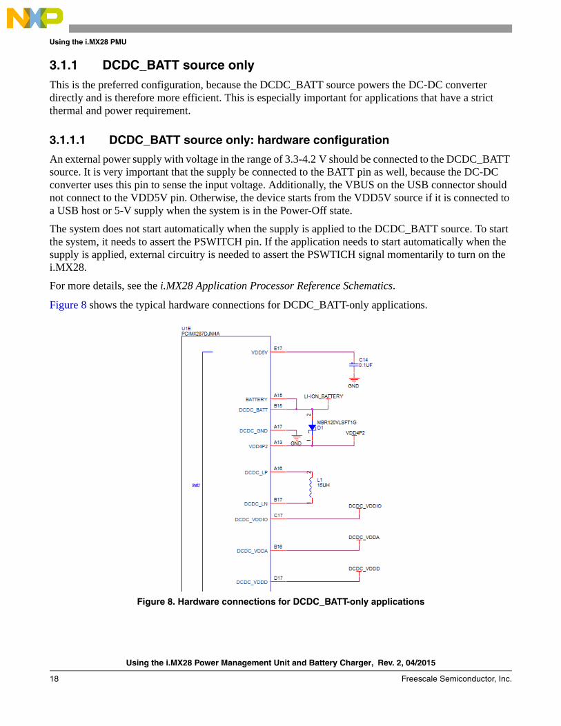
3.1.1 DCDC_BATT source onlyThis is the preferred configuration, because the DCDC_BATT source powers the DC-DC converter directly and is therefore more efficient. This is especially important for applications that have a strict thermal and power requirement.
3.1.1.1 DCDC_BATT source only: hardware configuration
An external power supply with voltage in the range of 3.3-4.2 V should be connected to the DCDC_BATT source. It is very important that the supply be connected to the BATT pin as well, because the DC-DC converter uses this pin to sense the input voltage. Additionally, the VBUS on the USB connector should not connect to the VDD5V pin. Otherwise, the device starts from the VDD5V source if it is connected to a USB host or 5-V supply when the system is in the Power-Off state.
The system does not start automatically when the supply is applied to the DCDC_BATT source. To start the system, it needs to assert the PSWITCH pin. If the application needs to start automatically when the supply is applied, external circuitry is needed to assert the PSWTICH signal momentarily to turn on the i.MX28.
For more details, see the i.MX28 Application Processor Reference Schematics.
Figure 8 shows the typical hardware connections for DCDC_BATT-only applications.
Figure 8. Hardware connections for DCDC_BATT-only applications
Using the i.MX28 Power Management Unit and Battery Charger, Rev. 2, 04/2015
Freescale Semiconductor, Inc. 19
Using the i.MX28 PMU
3.1.1.2 DCDC_BATT source only: software configuration
For an application that uses the DCDC_BATT source only, the NO_VDD5V_SOURCE needs to be defined on power_prep.c in the bootlet codes. Additionally, the programmer should ensure that NO_DCDC_BATT_SOURCE is not defined. For more details, see the Linux BSP Linux BSP User’s Guide.
Features of software configuration using DCDC_BATT source only
• The transfer of the power source from DCDC_BATT to VDD5V is permanently disabled
• The battery charger is disabled
• Automatic battery brownout shutdown is enabled to ensure the device can shut down properly under power interruptions
• Support for low-power modes including standby and Suspend-to-RAM
3.1.2 VDD5V source only
3.1.2.1 VDD5V source only: hardware configuration
An external 5-V power supply should be connected to the VDD5V source only. Additionally, a 1-k resistor is needed to place between the 4P2 rail and the DCDC_BATT pin, as well as between the 4P2 rail and the BATT pin to ensure the internal circuits are properly biased. The device starts automatically when a 5-V supply is applied. However, the device cannot be put in the Power-Off state when using the VDD5V source because the internal LinRegs are always turned on when there is a valid 5-V supply on VDD5V. The device restarts automatically after a reset or shutdown event. As the Suspend-To-RAM feature requires that the i.MX28 be put in the Power-Off state, this mode cannot be supported in this configuration.
For more details, see the i.MX28 Reference Schematics.
Using the i.MX28 Power Management Unit and Battery Charger, Rev. 2, 04/2015
20 Freescale Semiconductor, Inc.
Using the i.MX28 PMU
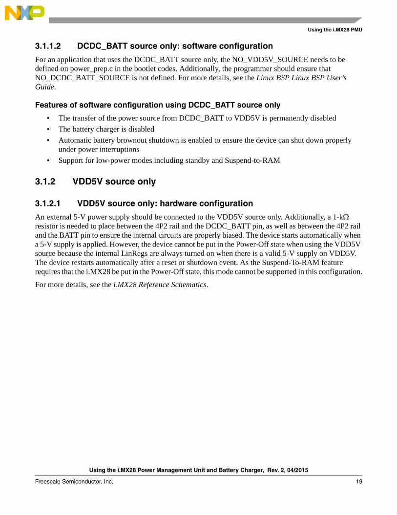
Figure 9 shows the typical hardware connections for VDD5V only application.
Figure 9. Hardware connections for VDD5V-only applications
Limitations
The VDD5V source–only configuration is a less power-efficient option than the DCDC_BATT option, because the VDD5V supply is first regulated to 4.2 V by LinReg to power the DC-DC converter instead of the DC-DC converter being powered directly.
Additionally, special consideration is needed for the hardware design in this configuration as the i.MX28 PMU is running on internal LinRegs on startup. The internal LinRegs have the following limitations:
• During the early stage of device startup, before on-chip ROM execution, the input current on VDD5V is limited to 100 mA.
• The device is running on internal LinRegs on power up, and it needs to wait for the software to set up the 4P2 rail before switching to the DC-DC converter as the power supply. The output current from LinRegs is much lower than that of the DC-DC converter.
It is strongly suggested to use the i.MX28 power supply to power the i.MX28 and core components like DRAM, NAND, and eMMC only. External supply is recommended for other peripherals like the Ethernet PHY and Wi-Fi modules.
Using the i.MX28 Power Management Unit and Battery Charger, Rev. 2, 04/2015
Freescale Semiconductor, Inc. 21
Using the i.MX28 PMU
4.1.2.2 VDD5V source only: software configuration
For an application that uses the VDD5V source only, NO_DCDC_BATT_SOURCE must be defined on power_prep.c in the bootlet codes. Additionally, the programmer should ensure that NO_VDD5V_SOURCE is not defined. For more details, see to the Linux BSP User’s Guide.
Features of software configuration using VDD5V source only
• The transfer of the power source from VDD5V to DCDC_BATT is permanently disabled.
• The battery charger is disabled.
• 4P2 rail is enabled to power the DC-DC converter.
• Automatic VDD5V and VDD4P2 brownout shutdowns are enabled to ensure the device can shut down properly under power interruptions.
• The only low-power mode supported is standby. Suspend-To-RAM mode cannot be supported due to hardware limitations.
3.2 Battery-powered applicationsFor battery-powered applications, the DCDC_BATT source should be used and connected to the Li-ion battery directly. This is the primary supply for the device. Optionally, the VDD5V source can be connected to a USB host port or a 5-V AC adaptor for charging the Li-ion battery.
3.2.1 Battery-powered applications: hardware configurationThe hardware connections should follow those described in the i.MX28 Reference Schematics.
Using the i.MX28 Power Management Unit and Battery Charger, Rev. 2, 04/2015
22 Freescale Semiconductor, Inc.
Using the i.MX28 PMU
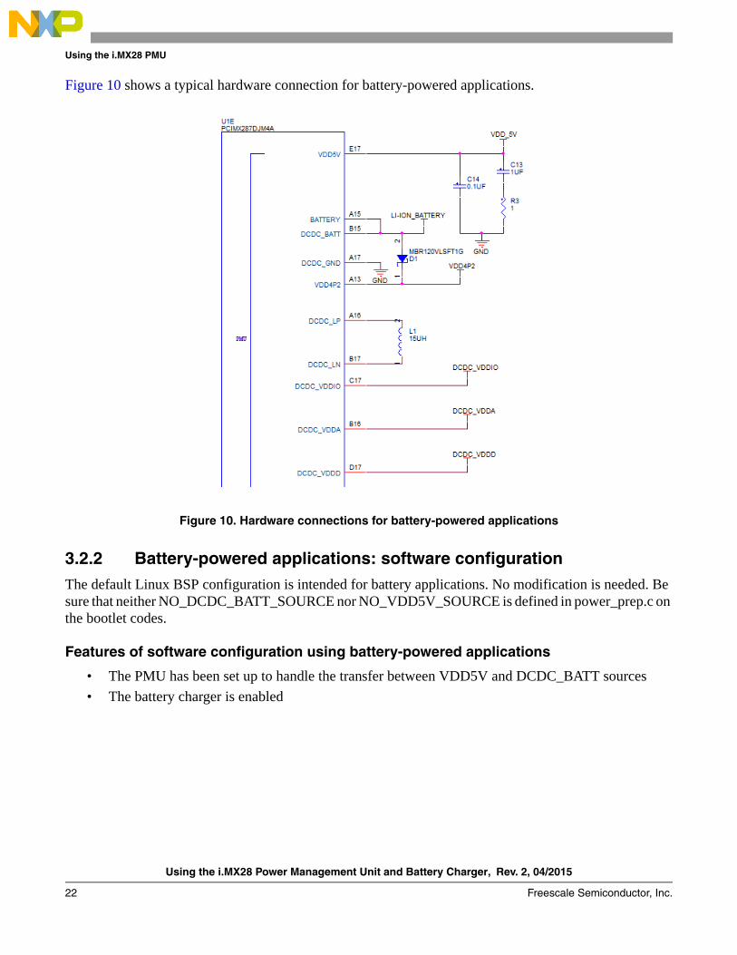
Figure 10 shows a typical hardware connection for battery-powered applications.
Figure 10. Hardware connections for battery-powered applications
3.2.2 Battery-powered applications: software configurationThe default Linux BSP configuration is intended for battery applications. No modification is needed. Be sure that neither NO_DCDC_BATT_SOURCE nor NO_VDD5V_SOURCE is defined in power_prep.c on the bootlet codes.
Features of software configuration using battery-powered applications
• The PMU has been set up to handle the transfer between VDD5V and DCDC_BATT sources
• The battery charger is enabled
Using the i.MX28 Power Management Unit and Battery Charger, Rev. 2, 04/2015
Freescale Semiconductor, Inc. 23
Using the i.MX28 PMU
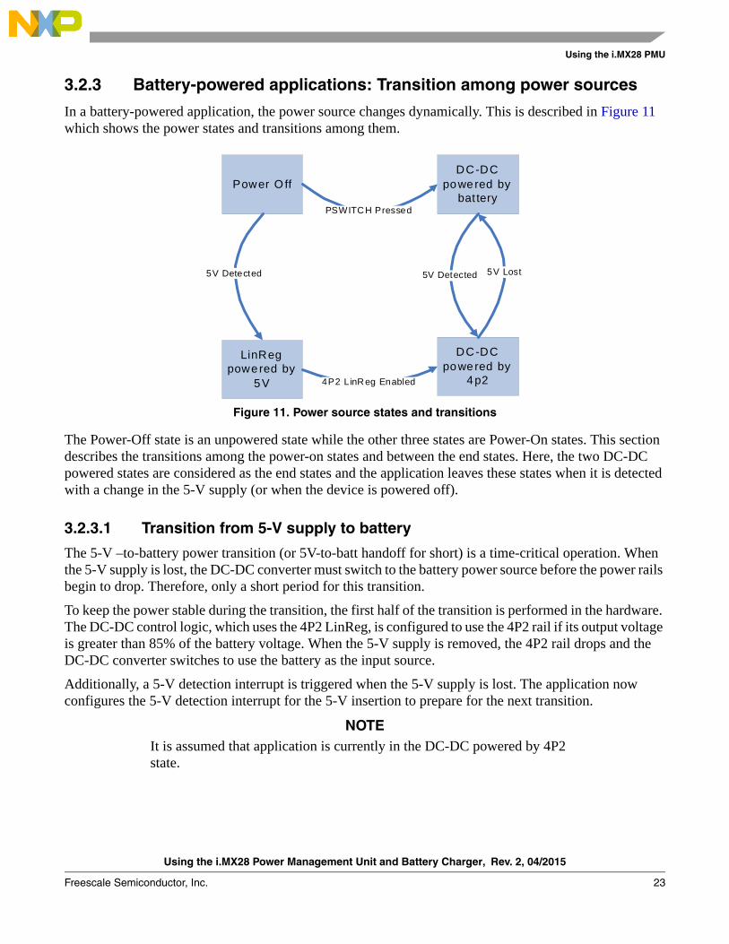
3.2.3 Battery-powered applications: Transition among power sources
In a battery-powered application, the power source changes dynamically. This is described in Figure 11 which shows the power states and transitions among them.
Figure 11. Power source states and transitions
The Power-Off state is an unpowered state while the other three states are Power-On states. This section describes the transitions among the power-on states and between the end states. Here, the two DC-DC powered states are considered as the end states and the application leaves these states when it is detected with a change in the 5-V supply (or when the device is powered off).
3.2.3.1 Transition from 5-V supply to battery
The 5-V –to-battery power transition (or 5V-to-batt handoff for short) is a time-critical operation. When the 5-V supply is lost, the DC-DC converter must switch to the battery power source before the power rails begin to drop. Therefore, only a short period for this transition.
To keep the power stable during the transition, the first half of the transition is performed in the hardware. The DC-DC control logic, which uses the 4P2 LinReg, is configured to use the 4P2 rail if its output voltage is greater than 85% of the battery voltage. When the 5-V supply is removed, the 4P2 rail drops and the DC-DC converter switches to use the battery as the input source.
Additionally, a 5-V detection interrupt is triggered when the 5-V supply is lost. The application now configures the 5-V detection interrupt for the 5-V insertion to prepare for the next transition.
NOTEIt is assumed that application is currently in the DC-DC powered by 4P2 state.
DC-DC powered by
bat tery
DC-DC powered by
4p2
LinReg powered by
5V
Power O ff
5V Detected 5V Detected 5V Lost
PSWITCH Pressed
4P2 L inReg Enabled
Using the i.MX28 Power Management Unit and Battery Charger, Rev. 2, 04/2015
24 Freescale Semiconductor, Inc.
Using the i.MX28 PMU
3.2.3.2 Transition from battery to 5-V power source
Unlike the 5V-to-batt handoff, the battery-to-5-V power transition (batt-to-5V handoff) is not time critical and therefore can be handled in the software. As the power from the battery is available when 5 V are applied, there is no time limit to perform the batt-to-5V handoff. Therefore, there is no time limit to perform the batt-to-5V handoff. An interrupt is triggered when 5 V are applied; the software then enables the 4P2 LinReg and sets up the DC-DC converter to use the 4P2 LinReg as the input. Additionally, the software configures the 5-V detection mechanism to check for 5-V removal for the next transition.
NOTEIt is assumed that the application is currently in the DC-DC Powered-By-Battery state.
3.2.4 Battery-powered applications: Battery chargingThe battery charger is only enabled for battery-powered configuration. For applications using a permanent supply, the Linux BSP disables the battery charger. The battery charger can be used as long as the VDD5V source is available. The charger shares from the VDD5V source with the 4P2 rail and generally, this does not cause any problem in the system. Current arbitration is done automatically only when the 4P2 rail is heavily loaded.
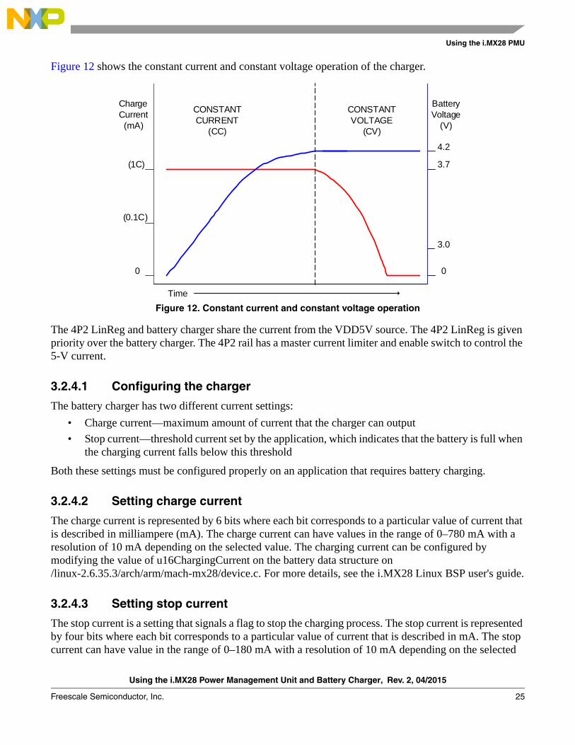
The i.MX28 battery charger has a two-stage operation—constant current and constant voltage. In the constant current state, the charge current is set by the application and the battery voltage is set below 4.2 V. As the battery receives current, the battery voltage rises. When the battery voltage reaches 4.2 V, the battery charger hardware lowers the current while keeping the battery voltage at 4.2 V. This begins the constant voltage stage. The hardware continues to lower the current until an internal current sensor detects that the battery current has reached a pre-determined threshold which is set by the application. This ends the battery charging process.
Using the i.MX28 Power Management Unit and Battery Charger, Rev. 2, 04/2015
Freescale Semiconductor, Inc. 25
Using the i.MX28 PMU
Figure 12 shows the constant current and constant voltage operation of the charger.
Figure 12. Constant current and constant voltage operation
The 4P2 LinReg and battery charger share the current from the VDD5V source. The 4P2 LinReg is given priority over the battery charger. The 4P2 rail has a master current limiter and enable switch to control the 5-V current.
3.2.4.1 Configuring the charger
The battery charger has two different current settings:
• Charge current—maximum amount of current that the charger can output
• Stop current—threshold current set by the application, which indicates that the battery is full when the charging current falls below this threshold
Both these settings must be configured properly on an application that requires battery charging.
3.2.4.2 Setting charge current
The charge current is represented by 6 bits where each bit corresponds to a particular value of current that is described in milliampere (mA). The charge current can have values in the range of 0–780 mA with a resolution of 10 mA depending on the selected value. The charging current can be configured by modifying the value of u16ChargingCurrent on the battery data structure on /linux-2.6.35.3/arch/arm/mach-mx28/device.c. For more details, see the i.MX28 Linux BSP user's guide.
3.2.4.3 Setting stop current
The stop current is a setting that signals a flag to stop the charging process. The stop current is represented by four bits where each bit corresponds to a particular value of current that is described in mA. The stop current can have value in the range of 0–180 mA with a resolution of 10 mA depending on the selected
ChargeCurrent (mA)
BatteryVoltage
(V)
(1C)
(0.1C)
4.2
3.7
3.0
0
Time
0
CONSTANT CURRENT
(CC)
CONSTANT VOLTAGE
(CV)
Using the i.MX28 Power Management Unit and Battery Charger, Rev. 2, 04/2015
26 Freescale Semiconductor, Inc.
Thermal overload protection
value. The stop current can be configured by modifying the value of u16ChargingThresholdCurrent on the battery data structure on /linux-2.6.35.3/arch/arm/mach-mx28/device.c. For more details, see the i.MX28 Linux BSP User's Guide.
4 Thermal overload protectionThe i.MX28 processor integrates a thermal-overload protection circuit to shut down the device when the on-die temperature exceeds a programmed target value. In the i.MX28 processor, a bipolar-based voltage generator tracks the on-die temperature and generates a temperature-dependant voltage. This voltage is compared with a fixed voltage level. This triggers the device shutdown if the temperature-dependant voltage is greater than the fixed voltage.
The thermal-overload protection circuit is configured by the HW_POWER_THERMAL register. By default, this circuit is disabled. The default thermal trip point for this circuit is 115 ºC and can be programmed up to 150 ºC in steps of 5 ºC. To ensure the proper operation of the system, the die temperature should not exceed the maximum junction temperature specified on the i.MX28 applications processor datasheets (automotive: IMX28AEC; consumer: IMX28CEC). The system operation at a higher temperature can cause permanent damages to the i.MX28 processor and the proper operation cannot be guaranteed.
4.1 Enabling thermal overload protectionThe steps to enable the thermal overload protection with the thermal trip point at 115 ºC are as follows:
1. Convert 115 ºC to the corresponding register setting:The formula to calculate the threshold temperature is provided in Equation 3:
THRESHOLD_TEMP = BASE_TEMP + (STEP_SIZE NUM_STEPS) Eqn. 3
Applying the corresponding values in Equation 3, 115 = 115 + (5 NUM_STEPS)Therefore, NUM_STEPS = 0
2. Write the threshold temperature to the thermal reset register field:HW_POWER_THERMAL [TEMP_THRESHOLD] = 0
3. Enable the thermal overload protection:HW_POWER_THERMAL [PWD] = 0
NOTEThe LRADC channels, 8 and 9, are dedicated for the internal die temperature sensing. They should also be enabled for the thermal overload protection. For more information, see the LRADC section of the i.MX28 Applications Processor Reference Manual.
NOTEThe 32-KHz crystal has to be running for the thermal protection circuit to operate properly. For more information, see the Real-time clock alarm watchdog persistent bits section of the i.MX28 Application Processors Reference Manual.
Using the i.MX28 Power Management Unit and Battery Charger, Rev. 2, 04/2015
Freescale Semiconductor, Inc. 27
Conclusion
5 ConclusionThe i.MX28 processor offers a highly efficient and comprehensive power supply. The instruction and descriptions provided in this application note should help configuring the PMU on the i.MX28 processor to maximize its power performance in applications using different input power sources.
6 ReferencesThis document includes references to the following documents available on www.freescale.com :
• i.MX28 Applications Processors for Automotive Parts (datasheet, document ID #IMX28AEC)
• i.MX28 Applications Processors for Consumer Parts (datasheet, document ID #IMX28CEC)
• i.MX28 Applications Processor Reference Manual (document ID #MCIMX28RM)
• i.MX28 Linux BSP User’s Guide (document ID #924-76408)
i.MX28 Reference Schematics ( www.freescale.com/webapp/sps/site/prod_summary.jsp?code=i.MX280&nodeId=018rH3ZrDRA24A&fpsp=1&tab=Design_Tools_Tab )
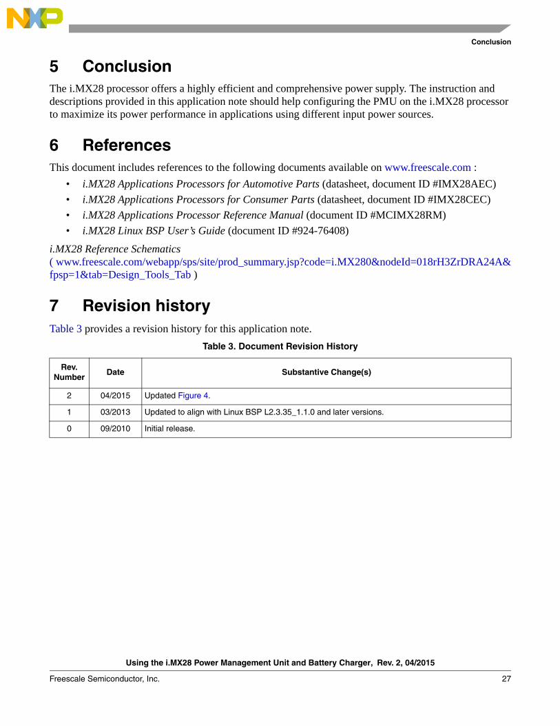
7 Revision history Table 3 provides a revision history for this application note.
Table 3. Document Revision History
Rev.Number
Date Substantive Change(s)
2 04/2015 Updated Figure 4.
1 03/2013 Updated to align with Linux BSP L2.3.35_1.1.0 and later versions.
0 09/2010 Initial release.
Document Number: AN4199Rev. 204/2015
Information in this document is provided solely to enable system and software
implementers to use Freescale products. There are no express or implied copyright
licenses granted hereunder to design or fabricate any integrated circuits based on the
information in this document.
Freescale reserves the right to make changes without further notice to any products
herein. Freescale makes no warranty, representation, or guarantee regarding the
suitability of its products for any particular purpose, nor does Freescale assume any
liability arising out of the application or use of any product or circuit, and specifically
disclaims any and all liability, including without limitation consequential or incidental
damages. “Typical” parameters that may be provided in Freescale data sheets and/or
specifications can and do vary in different applications, and actual performance may
vary over time. All operating parameters, including “typicals,” must be validated for each
customer application by customer’s technical experts. Freescale does not convey any
license under its patent rights nor the rights of others. Freescale sells products pursuant
to standard terms and conditions of sale, which can be found at the following address:
freescale.com/SalesTermsandConditions.
How to Reach Us:
Home Page: freescale.com
Web Support: freescale.com/support
Freescale and the Freescale logo are trademarks of Freescale Semiconductor, Inc.,
Reg. U.S. Pat. & Tm. Off. ARM and Cortex are registered trademarks of ARM Limited
(or its subsidiaries) in the EU and/or elsewhere. All rights reserved. All other product or
service names are the property of their respective owners.
© 2010, 2013, 2015 Freescale Semiconductor, Inc.