Embed Size (px)
Citation preview
Using the Digital I/O interface of Microchip
PIC18F Microcontrollers
Corrado Santoro
ARSLAB - Autonomous and Robotic Systems LaboratoryDipartimento di Matematica e Informatica - Universita di Catania, Italy
L.A.P. 1 Course
Corrado Santoro Digital I/O in PIC18F Family
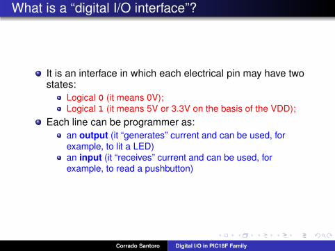
What is a “digital I/O interface”?
It is an interface in which each electrical pin may have twostates:
Logical 0 (it means 0V);
Logical 1 (it means 5V or 3.3V on the basis of the VDD);
Each line can be programmer as:
an output (it “generates” current and can be used, for
example, to lit a LED)
an input (it “receives” current and can be used, forexample, to read a pushbutton)
Corrado Santoro Digital I/O in PIC18F Family

Digital Input: Electrical consideration
An input connected to VDD is read (by software) as “1”
An input connected to Ground is read (by software) as “0”
If the input is floating (not connected) the value read cannot be
determined!
Corrado Santoro Digital I/O in PIC18F Family
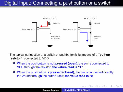
Digital Input: Connecting a pushbutton or a switch
The typical connection of a switch or pushbutton is by means of a “pull-up
resistor”, connected to VDD.
When the pushbutton is not pressed (open), the pin is connected to
VDD through the resistor; the valure read is “1”
When the pushbutton is pressed (closed), the pin is connected directly
to Ground through the button itself; the value read is “0”
Corrado Santoro Digital I/O in PIC18F Family
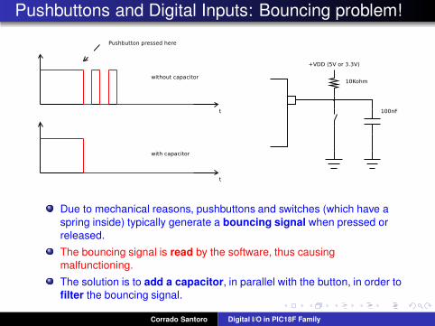
Pushbuttons and Digital Inputs: Bouncing problem!
Due to mechanical reasons, pushbuttons and switches (which have a
spring inside) typically generate a bouncing signal when pressed or
released.
The bouncing signal is read by the software, thus causing
malfunctioning.
The solution is to add a capacitor, in parallel with the button, in order to
filter the bouncing signal.
Corrado Santoro Digital I/O in PIC18F Family
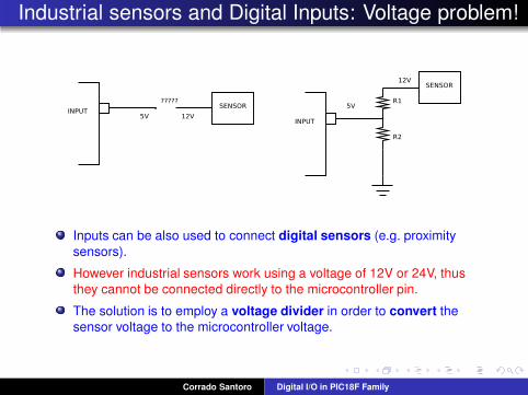
Industrial sensors and Digital Inputs: Voltage problem!
Inputs can be also used to connect digital sensors (e.g. proximity
sensors).
However industrial sensors work using a voltage of 12V or 24V, thus
they cannot be connected directly to the microcontroller pin.
The solution is to employ a voltage divider in order to convert the
sensor voltage to the microcontroller voltage.
Corrado Santoro Digital I/O in PIC18F Family
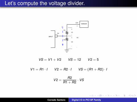
Let’s compute the voltage divider.
VS = V1 + V2 VS = 12 V2 = 5
V1 = R1 · I V2 = R2 · I VS = (R1 + R2) · I
V2 =R2
R1 + R2· VS
Corrado Santoro Digital I/O in PIC18F Family
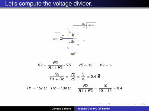
Let’s compute the voltage divider.
V2 =R2
R1 + R2· VS VS = 12 V2 = 5
R2
R1 + R2=
V2
VS=
5
12= 0.416
R1 = 15KΩ R2 = 10KΩR2
R1 + R2=
10
10 + 15= 0.4
Corrado Santoro Digital I/O in PIC18F Family
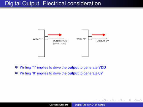
Digital Output: Electrical consideration
Writing “1” implies to drive the output to generate VDD
Writing “0” implies to drive the output to generate 0V
Corrado Santoro Digital I/O in PIC18F Family
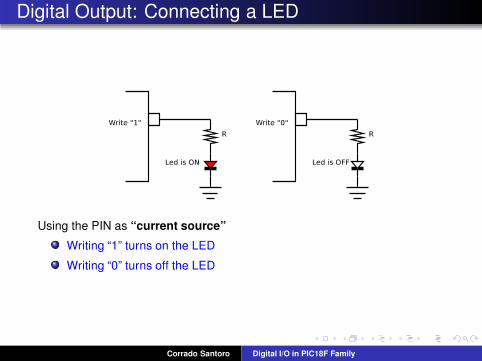
Digital Output: Connecting a LED
Using the PIN as “current source”
Writing “1” turns on the LED
Writing “0” turns off the LED
Corrado Santoro Digital I/O in PIC18F Family
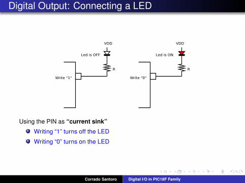
Digital Output: Connecting a LED
Using the PIN as “current sink”
Writing “1” turns off the LED
Writing “0” turns on the LED
Corrado Santoro Digital I/O in PIC18F Family
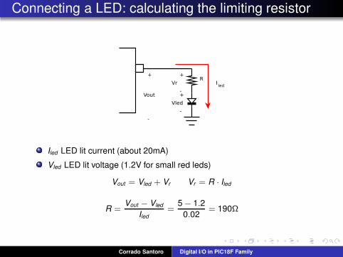
Connecting a LED: calculating the limiting resistor
Iled LED lit current (about 20mA)
Vled LED lit voltage (1.2V for small red leds)
Vout = Vled + Vr Vr = R · Iled
R =Vout − Vled
Iled
=5 − 1.2
0.02= 190Ω
Corrado Santoro Digital I/O in PIC18F Family

The Digital Interface of PIC18
MCUs of the PIC18 family have 5 digital ports, called PORT A, PORT
B, ..., PORT E.
Each port has 8 bits and thus 8 electrical pins
Pins are referred as Rxy, where x is the port name (A, B, ..., E) and y is
the bit (0, 1, ..., 7).
As an example, the pin RC3 is the bit 3 of the port C.
However, not all bits are mapped to electrical pins. This is a choice
“by-design”.
Corrado Santoro Digital I/O in PIC18F Family
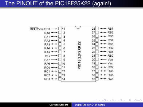
The PINOUT of the PIC18F25K22 (again!)
Corrado Santoro Digital I/O in PIC18F Family

Digital I/O and SFR
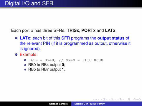
Each port x has three SFRs: TRISx, PORTx and LATx.
TRISx: each bit of this SFR programs the relevant PIN asinput or output:
A 0 means outputA 1 means input
Example:
TRISC = 0x30; // 0x30 = 0011 0000
RC0 to RC3:outputs;RC4, RC5: inputs;
RC6, RC7:outputs;
Corrado Santoro Digital I/O in PIC18F Family
Digital I/O and SFR
Each port x has three SFRs: TRISx, PORTx and LATx.
LATx: each bit of this SFR programs the output status of
the relevant PIN (if it is programmed as output, otherwise it
is ignored).
Example:
LATB = 0xe0; // 0xe0 = 1110 0000
RB0 to RB4 output 0;RB5 to RB7 output 1.
Corrado Santoro Digital I/O in PIC18F Family
Digital I/O and SFR
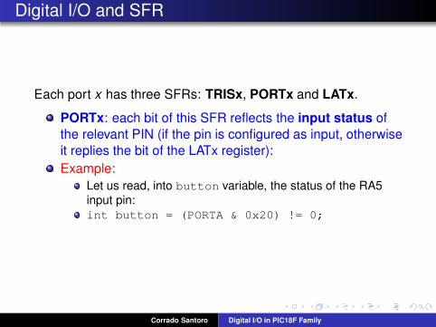
Each port x has three SFRs: TRISx, PORTx and LATx.
PORTx: each bit of this SFR reflects the input status of
the relevant PIN (if the pin is configured as input, otherwise
it replies the bit of the LATx register):
Example:
Let us read, into button variable, the status of the RA5
input pin:
int button = (PORTA & 0x20) != 0;
Corrado Santoro Digital I/O in PIC18F Family

Digital I/O and SFR: Summary
TRISx: programs the relevant PIN as input or output:
A 0 means outputA 1 means input
LATx: output status of the relevant PIN (if it is
programmed as output, otherwise it is ignored).
PORTx: input status of the relevant PINs (if the pin is
configured as input, otherwise it replies the bit of the LATx
register)
Corrado Santoro Digital I/O in PIC18F Family
Bit Mask Operations
Bit Mask Operations
Corrado Santoro Digital I/O in PIC18F Family
Bit Mask Operations
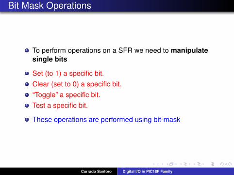
To perform operations on a SFR we need to manipulate
single bits
Set (to 1) a specific bit.
Clear (set to 0) a specific bit.
“Toggle” a specific bit.
Test a specific bit.
These operations are performed using bit-mask
Corrado Santoro Digital I/O in PIC18F Family

Setting a bit
Make an OR operation with a constant bit pattern formedas follows:
The bit to be set is “1”
All the other bits are “0”
Example: setting the bit 3 of the (8-bit) variable A:
A B7 B6 B5 B4 B3 B2 B1 B0 OR
mask 0 0 0 0 1 0 0 0 =
A B7 B6 B5 B4 1 B2 B1 B0
A = A | 0x08;
A |= 0x08;
Corrado Santoro Digital I/O in PIC18F Family

Clearing a bit
Make an AND operation with a constant bit pattern formedas follows:
The bit to be cleared is “0”
All the other bits are “1”
Example: clearing the bit 6 of the (8-bit) variable A:
A B7 B6 B5 B4 B3 B2 B1 B0 AND
mask 1 0 1 1 1 1 1 1 =
A B7 0 B5 B4 B3 B2 B1 B0
A = A & 0xbf;
A &= 0xbf;
Corrado Santoro Digital I/O in PIC18F Family
Toggling a bit
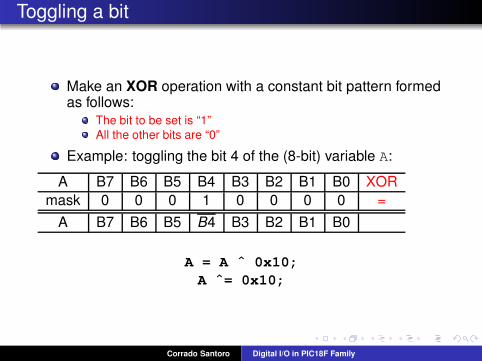
Make an XOR operation with a constant bit pattern formedas follows:
The bit to be set is “1”
All the other bits are “0”
Example: toggling the bit 4 of the (8-bit) variable A:
A B7 B6 B5 B4 B3 B2 B1 B0 XOR
mask 0 0 0 1 0 0 0 0 =
A B7 B6 B5 B4 B3 B2 B1 B0
A = A ˆ 0x10;
A ˆ= 0x10;
Corrado Santoro Digital I/O in PIC18F Family
Testing a bit
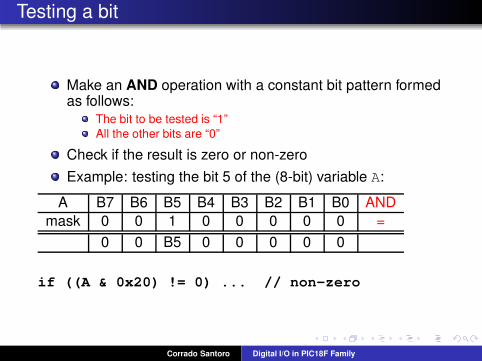
Make an AND operation with a constant bit pattern formedas follows:
The bit to be tested is “1”
All the other bits are “0”
Check if the result is zero or non-zero
Example: testing the bit 5 of the (8-bit) variable A:
A B7 B6 B5 B4 B3 B2 B1 B0 AND
mask 0 0 1 0 0 0 0 0 =
0 0 B5 0 0 0 0 0
if ((A & 0x20) != 0) ... // non-zero
Corrado Santoro Digital I/O in PIC18F Family

An Example
We have a circut where:
A pushbutton is connected to RA3;
A LED is connected to RB0.
Let us write a program that lits the LED with the pushbutton:
First configure RA3 as input and RB0 as output;
then use a continuous loop which copies RA3 to RB0.
Corrado Santoro Digital I/O in PIC18F Family

An Example
The listing
main()
TRISA |= 0x08; // RA3 as input
TRISB &= 0xfe; // RB0 as output
for (;;) // loop forever
if ((PORTA & 8) != 0) // read RA3
LATB |= 1; // write ‘‘1’’ to RB0
else
LATB &= 0xfe; // write ‘‘0’’ to RB0
Corrado Santoro Digital I/O in PIC18F Family
Manipulating bits
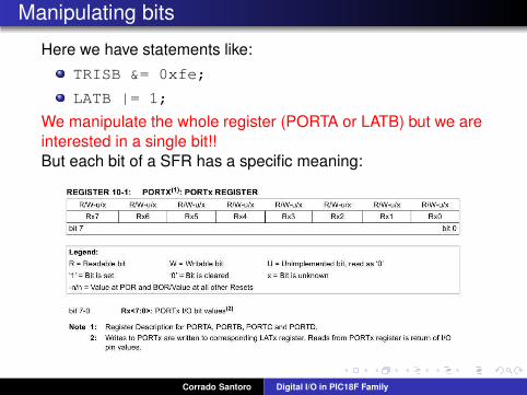
Here we have statements like:
TRISB &= 0xfe;
LATB |= 1;
We manipulate the whole register (PORTA or LATB) but we are
interested in a single bit!!
But each bit of a SFR has a specific meaning:
Corrado Santoro Digital I/O in PIC18F Family
Manipulating bits
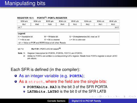
Each SFR is defined (in the compiler):
As an integer variable (e.g. PORTA);
As a struct, where the field are the single bits:
PORTAbits.RA3 is the bit 3 of the SFR PORTA
LATBbits.LATB0 is the bit 0 of the SFR LATB
Corrado Santoro Digital I/O in PIC18F Family
The example becomes
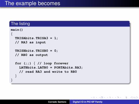
The listing
main()
TRISAbits.TRISA3 = 1;
// RA3 as input
TRISBbits.TRISB0 = 0;
// RB0 as output
for (;;) // loop forever
LATBbits.LATB0 = PORTAbits.RA3;
// read RA3 and write to RB0
Corrado Santoro Digital I/O in PIC18F Family

Using the Digital I/O interface of Microchip
PIC18F Microcontrollers
Corrado Santoro
ARSLAB - Autonomous and Robotic Systems LaboratoryDipartimento di Matematica e Informatica - Universita di Catania, Italy
L.A.P. 1 Course
Corrado Santoro Digital I/O in PIC18F Family