Embed Size (px)
Citation preview
C H A P T E R
Using the Border Gateway Protocol for Interdomain Routing 12-1
Using the Border Gateway Protocolfor Interdomain Routing
1 2
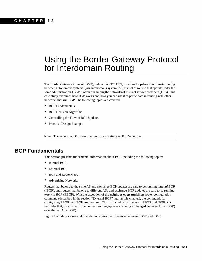
The Border Gateway Protocol (BGP), defined in RFC 1771, provides loop-free interdomain routingbetween autonomous systems. (An autonomous system [AS] is a set of routers that operate under thesame administration.) BGP is often run among the networks of Internet service providers (ISPs). Thiscase study examines how BGP works and how you can use it to participate in routing with othernetworks that run BGP. The following topics are covered:
• BGP Fundamentals
• BGP Decision Algorithm
• Controlling the Flow of BGP Updates
• Practical Design Example
Note The version of BGP described in this case study is BGP Version 4.
BGP FundamentalsThis section presents fundamental information about BGP, including the following topics:
• Internal BGP
• External BGP
• BGP and Route Maps
• Advertising Networks
Routers that belong to the same AS and exchange BGP updates are said to be runninginternal BGP(IBGP), and routers that belong to different ASs and exchange BGP updates are said to be runningexternal BGP (EBGP). With the exception of theneighbor ebgp-multihop router configurationcommand (described in the section “External BGP” later in this chapter), the commands forconfiguring EBGP and IBGP are the same. This case study uses the terms EBGP and IBGP as areminder that, for any particular context, routing updates are being exchanged between ASs (EBGP)or within an AS (IBGP).
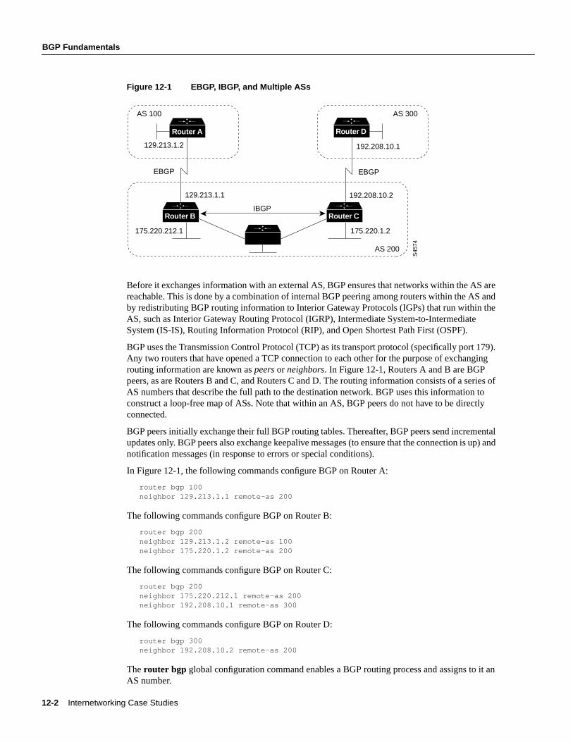
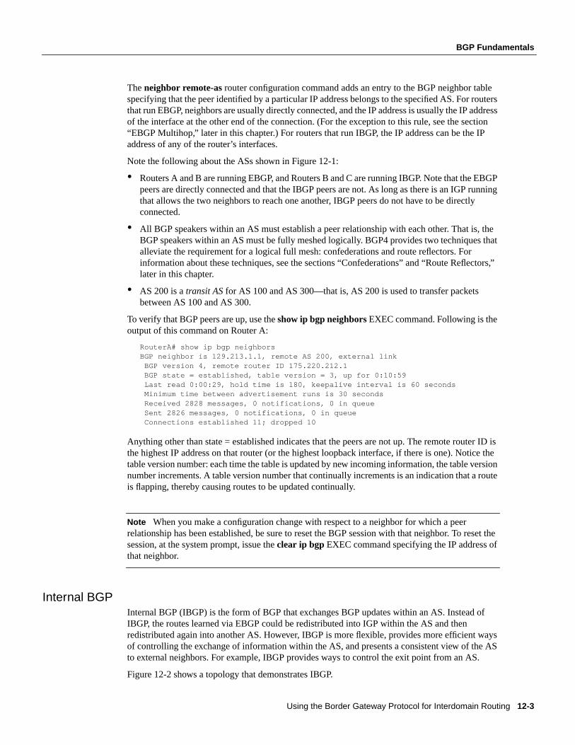
Figure 12-1 shows a network that demonstrates the difference between EBGP and IBGP.
12-2 Internetworking Case Studies
BGP Fundamentals
Figure 12-1 EBGP, IBGP, and Multiple ASs
Before it exchanges information with an external AS, BGP ensures that networks within the AS arereachable. This is done by a combination of internal BGP peering among routers within the AS andby redistributing BGP routing information to Interior Gateway Protocols (IGPs) that run within theAS, such as Interior Gateway Routing Protocol (IGRP), Intermediate System-to-IntermediateSystem (IS-IS), Routing Information Protocol (RIP), and Open Shortest Path First (OSPF).
BGP uses the Transmission Control Protocol (TCP) as its transport protocol (specifically port 179).Any two routers that have opened a TCP connection to each other for the purpose of exchangingrouting information are known aspeers or neighbors. In Figure 12-1, Routers A and B are BGPpeers, as are Routers B and C, and Routers C and D. The routing information consists of a series ofAS numbers that describe the full path to the destination network. BGP uses this information toconstruct a loop-free map of ASs. Note that within an AS, BGP peers do not have to be directlyconnected.
BGP peers initially exchange their full BGP routing tables. Thereafter, BGP peers send incrementalupdates only. BGP peers also exchange keepalive messages (to ensure that the connection is up) andnotification messages (in response to errors or special conditions).
In Figure 12-1, the following commands configure BGP on Router A:
router bgp 100neighbor 129.213.1.1 remote-as 200
The following commands configure BGP on Router B:
router bgp 200neighbor 129.213.1.2 remote-as 100neighbor 175.220.1.2 remote-as 200
The following commands configure BGP on Router C:
router bgp 200neighbor 175.220.212.1 remote-as 200neighbor 192.208.10.1 remote-as 300
The following commands configure BGP on Router D:
router bgp 300neighbor 192.208.10.2 remote-as 200
Therouter bgp global configuration command enables a BGP routing process and assigns to it anAS number.
AS 100
S45
74
AS 200
129.213.1.2
175.220.212.1
129.213.1.1 192.208.10.2
AS 300
EBGP EBGP
192.208.10.1
175.220.1.2
IBGPRouter B
Router A Router D
Router C
Using the Border Gateway Protocol for Interdomain Routing 12-3
BGP Fundamentals
Theneighbor remote-as router configuration command adds an entry to the BGP neighbor tablespecifying that the peer identified by a particular IP address belongs to the specified AS. For routersthat run EBGP, neighbors are usually directly connected, and the IP address is usually the IP addressof the interface at the other end of the connection. (For the exception to this rule, see the section“EBGP Multihop,” later in this chapter.) For routers that run IBGP, the IP address can be the IPaddress of any of the router’s interfaces.
Note the following about the ASs shown in Figure 12-1:
• Routers A and B are running EBGP, and Routers B and C are running IBGP. Note that the EBGPpeers are directly connected and that the IBGP peers are not. As long as there is an IGP runningthat allows the two neighbors to reach one another, IBGP peers do not have to be directlyconnected.
• All BGP speakers within an AS must establish a peer relationship with each other. That is, theBGP speakers within an AS must be fully meshed logically. BGP4 provides two techniques thatalleviate the requirement for a logical full mesh: confederations and route reflectors. Forinformation about these techniques, see the sections “Confederations” and “Route Reflectors,”later in this chapter.
• AS 200 is atransit AS for AS 100 and AS 300—that is, AS 200 is used to transfer packetsbetween AS 100 and AS 300.
To verify that BGP peers are up, use theshow ip bgp neighborsEXEC command. Following is theoutput of this command on Router A:
RouterA# show ip bgp neighborsBGP neighbor is 129.213.1.1, remote AS 200, external link BGP version 4, remote router ID 175.220.212.1 BGP state = established, table version = 3, up for 0:10:59 Last read 0:00:29, hold time is 180, keepalive interval is 60 seconds Minimum time between advertisement runs is 30 seconds Received 2828 messages, 0 notifications, 0 in queue Sent 2826 messages, 0 notifications, 0 in queue Connections established 11; dropped 10
Anything other than state = established indicates that the peers are not up. The remote router ID isthe highest IP address on that router (or the highest loopback interface, if there is one). Notice thetable version number: each time the table is updated by new incoming information, the table versionnumber increments. A table version number that continually increments is an indication that a routeis flapping, thereby causing routes to be updated continually.
Note When you make a configuration change with respect to a neighbor for which a peerrelationship has been established, be sure to reset the BGP session with that neighbor. To reset thesession, at the system prompt, issue theclear ip bgp EXEC command specifying the IP address ofthat neighbor.
Internal BGPInternal BGP (IBGP) is the form of BGP that exchanges BGP updates within an AS. Instead ofIBGP, the routes learned via EBGP could be redistributed into IGP within the AS and thenredistributed again into another AS. However, IBGP is more flexible, provides more efficient waysof controlling the exchange of information within the AS, and presents a consistent view of the ASto external neighbors. For example, IBGP provides ways to control the exit point from an AS.
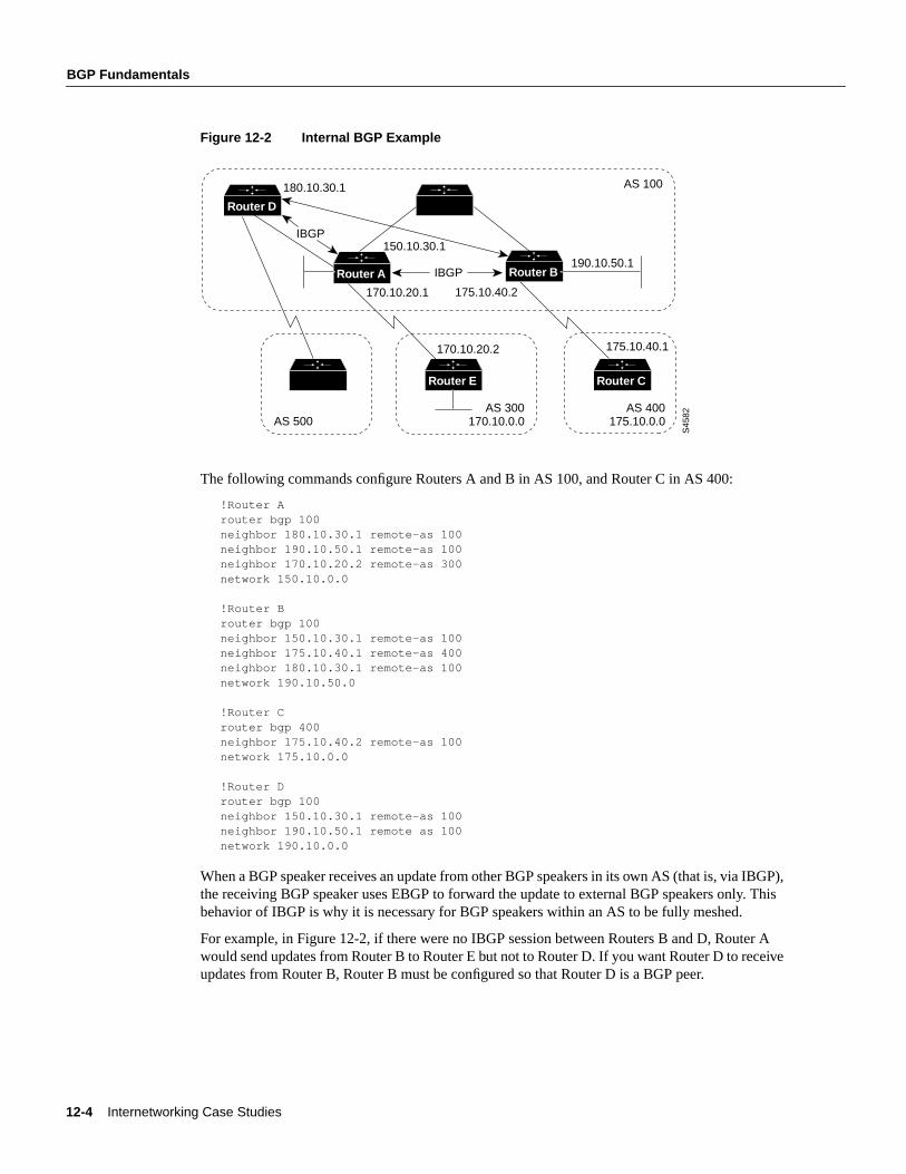
Figure 12-2 shows a topology that demonstrates IBGP.
12-4 Internetworking Case Studies
BGP Fundamentals
Figure 12-2 Internal BGP Example
The following commands configure Routers A and B in AS 100, and Router C in AS 400:
!Router Arouter bgp 100neighbor 180.10.30.1 remote-as 100neighbor 190.10.50.1 remote-as 100neighbor 170.10.20.2 remote-as 300network 150.10.0.0
!Router Brouter bgp 100neighbor 150.10.30.1 remote-as 100neighbor 175.10.40.1 remote-as 400neighbor 180.10.30.1 remote-as 100network 190.10.50.0
!Router Crouter bgp 400neighbor 175.10.40.2 remote-as 100network 175.10.0.0
!Router Drouter bgp 100neighbor 150.10.30.1 remote-as 100neighbor 190.10.50.1 remote as 100network 190.10.0.0
When a BGP speaker receives an update from other BGP speakers in its own AS (that is, via IBGP),the receiving BGP speaker uses EBGP to forward the update to external BGP speakers only. Thisbehavior of IBGP is why it is necessary for BGP speakers within an AS to be fully meshed.
For example, in Figure 12-2, if there were no IBGP session between Routers B and D, Router Awould send updates from Router B to Router E but not to Router D. If you want Router D to receiveupdates from Router B, Router B must be configured so that Router D is a BGP peer.
AS 300
S45
82
170.10.0.0AS 400
175.10.0.0
175.10.40.1
170.10.20.1
180.10.30.1
150.10.30.1
170.10.20.2
Router E
Router A
Router D
AS 100
IBGP
IBGP
190.10.50.1
175.10.40.2
Router B
AS 500
Router C
Using the Border Gateway Protocol for Interdomain Routing 12-5
BGP Fundamentals
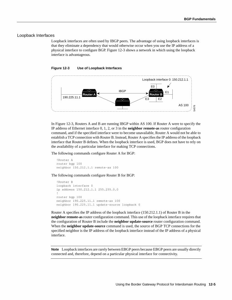
Loopback InterfacesLoopback interfaces are often used by IBGP peers. The advantage of using loopback interfaces isthat they eliminate a dependency that would otherwise occur when you use the IP address of aphysical interface to configure BGP. Figure 12-3 shows a network in which using the loopbackinterface is advantageous.
Figure 12-3 Use of Loopback Interfaces
In Figure 12-3, Routers A and B are running IBGP within AS 100. If Router A were to specify theIP address of Ethernet interface 0, 1, 2, or 3 in theneighbor remote-as router configurationcommand, and if the specified interface were to become unavailable, Router A would not be able toestablish a TCP connection with Router B. Instead, Router A specifies the IP address of the loopbackinterface that Router B defines. When the loopback interface is used, BGP does not have to rely onthe availability of a particular interface for making TCP connections.
The following commands configure Router A for BGP:
!Router Arouter bgp 100neighbor 150.212.1.1 remote-as 100
The following commands configure Router B for BGP:
!Router Bloopback interface 0ip address 150.212.1.1 255.255.0.0!router bgp 100neighbor 190.225.11.1 remote-as 100neighbor 190.225.11.1 update-source loopback 0
Router A specifies the IP address of the loopback interface (150.212.1.1) of Router B in theneighbor remote-asrouter configuration command. This use of the loopback interface requires thatthe configuration of Router B include theneighbor update-sourcerouter configuration command.When theneighbor update-source command is used, the source of BGP TCP connections for thespecified neighbor is the IP address of the loopback interface instead of the IP address of a physicalinterface.
Note Loopback interfaces are rarely between EBGP peers because EBGP peers are usually directlyconnected and, therefore, depend on a particular physical interface for connectivity.
AS 100
E1
E2E3
E0
S45
76
190.225.11.1
Loopback interface 0: 150.212.1.1
Router A Router BIBGP
12-6 Internetworking Case Studies
BGP Fundamentals
External BGPWhen two BGP speakers that are not in the same AS run BGP to exchange routing information, theyare said to be running EBGP. This section describes commands that solve configuration problemsthat arise when BGP routing updates are exchanged between different ASs:
• EBGP Multihop
• EBGP Load Balancing
• Synchronization
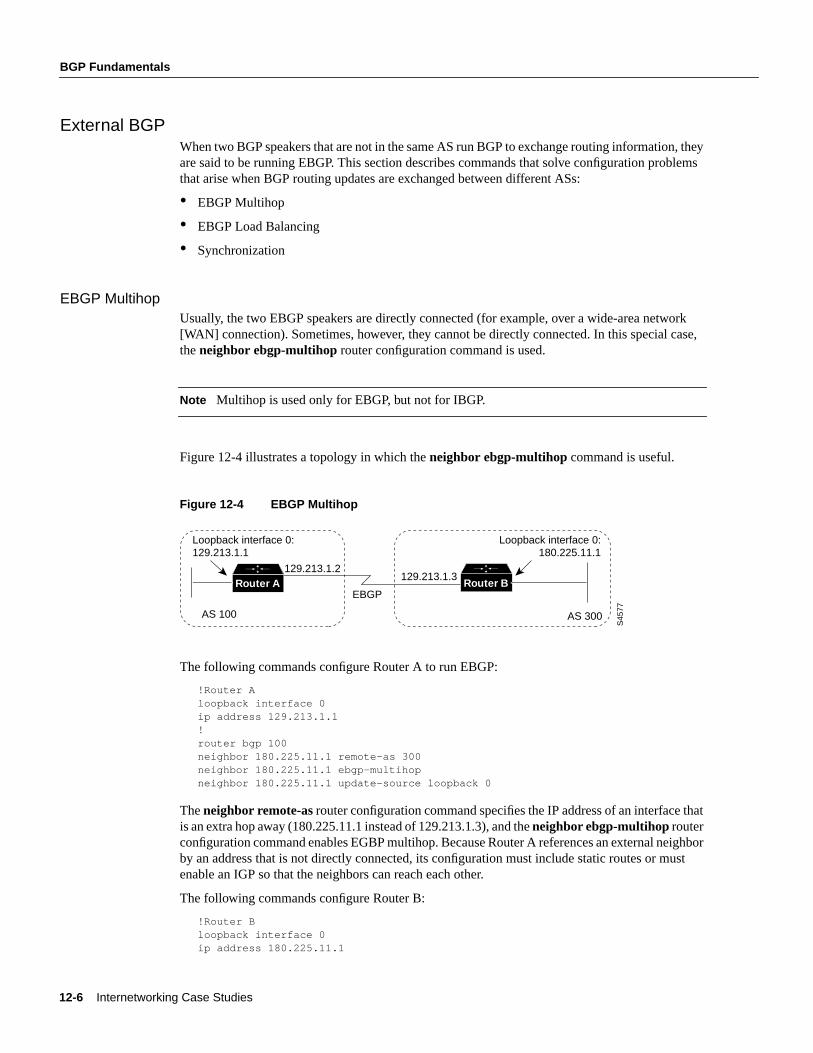
EBGP MultihopUsually, the two EBGP speakers are directly connected (for example, over a wide-area network[WAN] connection). Sometimes, however, they cannot be directly connected. In this special case,theneighbor ebgp-multihop router configuration command is used.
Note Multihop is used only for EBGP, but not for IBGP.
Figure 12-4 illustrates a topology in which theneighbor ebgp-multihop command is useful.
Figure 12-4 EBGP Multihop
The following commands configure Router A to run EBGP:
!Router Aloopback interface 0ip address 129.213.1.1!router bgp 100neighbor 180.225.11.1 remote-as 300neighbor 180.225.11.1 ebgp-multihopneighbor 180.225.11.1 update-source loopback 0
Theneighbor remote-asrouter configuration command specifies the IP address of an interface thatis an extra hop away (180.225.11.1 instead of 129.213.1.3), and theneighbor ebgp-multihoprouterconfiguration command enables EGBP multihop. Because Router A references an external neighborby an address that is not directly connected, its configuration must include static routes or mustenable an IGP so that the neighbors can reach each other.
The following commands configure Router B:
!Router Bloopback interface 0ip address 180.225.11.1
AS 100
Loopback interface 0:129.213.1.1
Loopback interface 0:180.225.11.1
EBGP
AS 300S
4577
129.213.1.3Router A Router B
129.213.1.2
Using the Border Gateway Protocol for Interdomain Routing 12-7
BGP Fundamentals
router bgp 300neighbor 129.213.1.1 remote-as 100neighbor 129.213.1.1 ebgp-multihopneighbor 129.213.1.1 update-source loopback 0
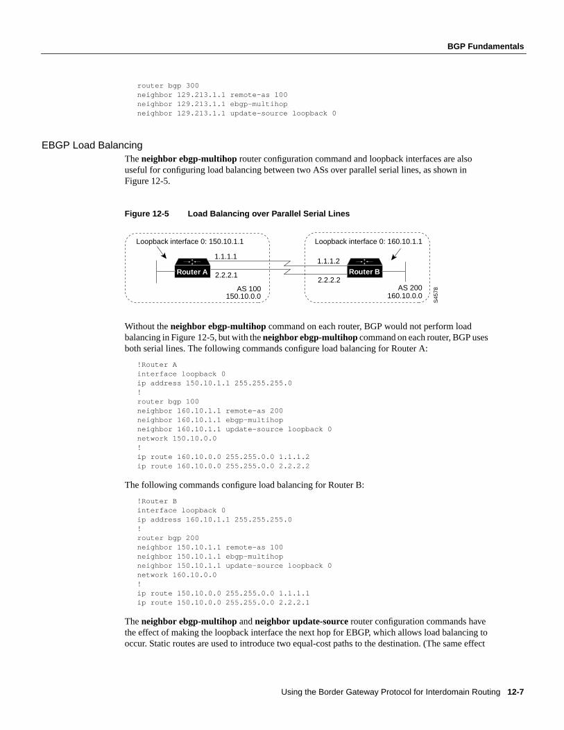
EBGP Load BalancingTheneighbor ebgp-multihop router configuration command and loopback interfaces are alsouseful for configuring load balancing between two ASs over parallel serial lines, as shown inFigure 12-5.
Figure 12-5 Load Balancing over Parallel Serial Lines
Without theneighbor ebgp-multihop command on each router, BGP would not perform loadbalancing in Figure 12-5, but with theneighbor ebgp-multihopcommand on each router, BGP usesboth serial lines. The following commands configure load balancing for Router A:
!Router Ainterface loopback 0ip address 150.10.1.1 255.255.255.0!router bgp 100neighbor 160.10.1.1 remote-as 200neighbor 160.10.1.1 ebgp-multihopneighbor 160.10.1.1 update-source loopback 0network 150.10.0.0!ip route 160.10.0.0 255.255.0.0 1.1.1.2ip route 160.10.0.0 255.255.0.0 2.2.2.2
The following commands configure load balancing for Router B:
!Router Binterface loopback 0ip address 160.10.1.1 255.255.255.0!router bgp 200neighbor 150.10.1.1 remote-as 100neighbor 150.10.1.1 ebgp-multihopneighbor 150.10.1.1 update-source loopback 0network 160.10.0.0!ip route 150.10.0.0 255.255.0.0 1.1.1.1ip route 150.10.0.0 255.255.0.0 2.2.2.1
Theneighbor ebgp-multihop andneighbor update-source router configuration commands havethe effect of making the loopback interface the next hop for EBGP, which allows load balancing tooccur. Static routes are used to introduce two equal-cost paths to the destination. (The same effect
AS 100 AS 200160.10.0.0
S45
78
1.1.1.1
2.2.2.1
1.1.1.2
2.2.2.2
150.10.0.0
Loopback interface 0: 160.10.1.1Loopback interface 0: 150.10.1.1
Router A Router B
12-8 Internetworking Case Studies
BGP Fundamentals
could also be accomplished by using an IGP.) Router A can reach the next hop of 160.10.1.1 in twoways: via 1.1.1.2 and via 2.2.2.2. Likewise, Router B can reach the next hop of 150.10.1.1 in twoways: via 1.1.1.1 and via 2.2.2.1.
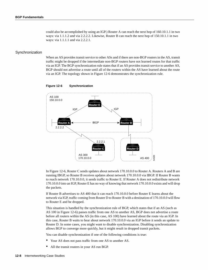
SynchronizationWhen an AS provides transit service to other ASs and if there are non-BGP routers in the AS, transittraffic might be dropped if the intermediate non-BGP routers have not learned routes for that trafficvia an IGP. The BGP synchronization rule states that if an AS provides transit service to another AS,BGP should not advertise a route until all of the routers within the AS have learned about the routevia an IGP. The topology shown in Figure 12-6 demonstrates the synchronization rule.
Figure 12-6 Synchronization
In Figure 12-6, Router C sends updates about network 170.10.0.0 to Router A. Routers A and B arerunning IBGP, so Router B receives updates about network 170.10.0.0 via IBGP. If Router B wantsto reach network 170.10.0.0, it sends traffic to Router E. If Router A does not redistribute network170.10.0.0 into an IGP, Router E has no way of knowing that network 170.10.0.0 exists and will dropthe packets.
If Router B advertises to AS 400 that it can reach 170.10.0.0 before Router E learns about thenetwork via IGP, traffic coming from Router D to Router B with a destination of 170.10.0.0 will flowto Router E and be dropped.
This situation is handled by the synchronization rule of BGP, which states that if an AS (such asAS 100 in Figure 12-6) passes traffic from one AS to another AS, BGP does not advertise a routebefore all routers within the AS (in this case, AS 100) have learned about the route via an IGP. Inthis case, Router B waits to hear about network 170.10.0.0 via an IGP before it sends an update toRouter D. In some cases, you might want to disable synchronization. Disabling synchronizationallows BGP to converge more quickly, but it might result in dropped transit packets.
You can disable synchronization if one of the following conditions is true:
• Your AS does not pass traffic from one AS to another AS.
• All the transit routers in your AS run BGP.
AS 300S
4589
170.10.0.0
AS 100150.10.0.0
IBGP
IGP IGP
2.2.2.2
2.2.2.1
Router C
Router E
Router A
AS 400
Router D
Router B
Using the Border Gateway Protocol for Interdomain Routing 12-9
BGP and Route Maps
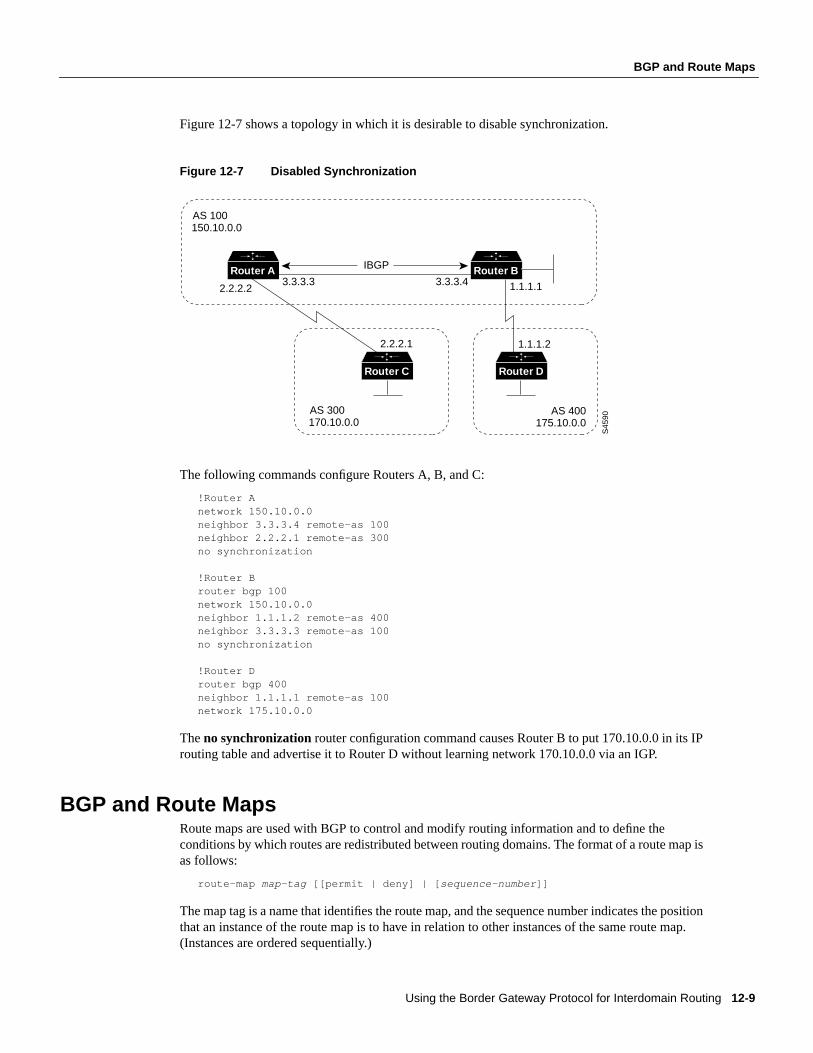
Figure 12-7 shows a topology in which it is desirable to disable synchronization.
Figure 12-7 Disabled Synchronization
The following commands configure Routers A, B, and C:
!Router Anetwork 150.10.0.0neighbor 3.3.3.4 remote-as 100neighbor 2.2.2.1 remote-as 300no synchronization
!Router Brouter bgp 100network 150.10.0.0neighbor 1.1.1.2 remote-as 400neighbor 3.3.3.3 remote-as 100no synchronization
!Router Drouter bgp 400neighbor 1.1.1.1 remote-as 100network 175.10.0.0
Theno synchronizationrouter configuration command causes Router B to put 170.10.0.0 in its IProuting table and advertise it to Router D without learning network 170.10.0.0 via an IGP.
BGP and Route MapsRoute maps are used with BGP to control and modify routing information and to define theconditions by which routes are redistributed between routing domains. The format of a route map isas follows:
route-map map-tag [[permit | deny] | [ sequence-number ]]
The map tag is a name that identifies the route map, and the sequence number indicates the positionthat an instance of the route map is to have in relation to other instances of the same route map.(Instances are ordered sequentially.)
AS 300
S45
90170.10.0.0
AS 100150.10.0.0
IBGP
2.2.2.23.3.3.3 3.3.3.4 1.1.1.1
1.1.1.22.2.2.1
Router C
Router A
AS 400175.10.0.0
Router D
Router B
12-10 Internetworking Case Studies
BGP and Route Maps
For example, you might use the following commands to define a route map named MYMAP:
route-map MYMAP permit 10! First set of conditions goes here.route-map MYMAP permit 20! Second set of conditions goes here.
When BGP applies MYMAP to routing updates, it applies the lowest instance first (in this case,instance 10). If the first set of conditions is not met, the second instance is applied, and so on, untileither a set of conditions has been met, or there are no more sets of conditions to apply.
Thematch andsetroute map configuration commands are used to define the condition portion of aroute map. Thematch command specifies a criteria that must be matched, and theset commandspecifies an action that is to be taken if the routing update meets the condition defined by thematchcommand.
Following is an example of a simple route map:
route-map MYMAP permit 10match ip address 1.1.1.1set metric 5
When an update matches IP address 1.1.1.1, BGP sets the metric for the update to 5, sends the update(because of thepermit keyword), and breaks out of the list of route-map instances.
When an update does not meet the criteria of an instance, BGP applies the next instance of the routemap to the update, and so on, until an action is taken, or there are no more route map instances toapply. If the update does not meet any criteria, the update is not redistributed or controlled.
When an update meets the match criteria, and the route map specifies thedenykeyword, BGP breaksout of the list of instances, and the update is not redistributed or controlled.
Note Route maps cannot be used to filter incoming BGP updates based on IP address. You can,however, use route maps to filter outgoing BGP updates based on IP address.
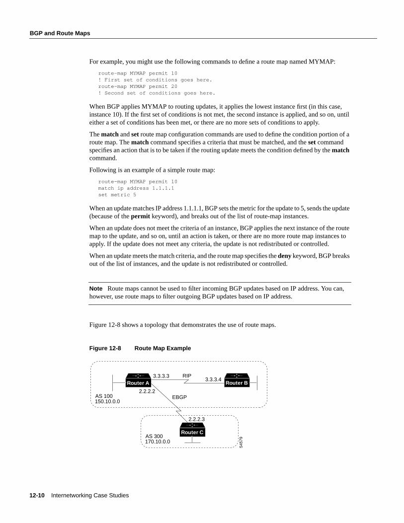
Figure 12-8 shows a topology that demonstrates the use of route maps.
Figure 12-8 Route Map Example
AS 100
S45
79
3.3.3.3
2.2.2.2
2.2.2.3
3.3.3.4
150.10.0.0
AS 300170.10.0.0
RIP
EBGP
Router A Router B
Router C
Using the Border Gateway Protocol for Interdomain Routing 12-11
BGP and Route Maps
In Figure 12-8, Routers A and B run RIP with each other, and Routers A and C run BGP with eachother. If you want Router A to redistribute routes from 170.10.0.0 with a metric of 2 and toredistribute all other routes with a metric of 5, use the following commands for Router A:
!Router Arouter ripnetwork 3.0.0.0network 2.0.0.0network 150.10.0.0passive-interface serial 0redistribute bgp 100 route-map SETMETRIC!router bgp 100neighbor 2.2.2.3 remote-as 300network 150.10.0.0!route-map SETMETRIC permit 10match ip-address 1set metric 2!route-map SETMETRIC permit 20set metric 5!access-list 1 permit 170.10.0.0 0.0.255.255
When a route matches the IP address 170.10.0.0, it is redistributed with a metric of 2. When a routedoes not match the IP address 170.10.0.0, its metric is set to 5, and the route is redistributed.
Assume that on Router C you want to set to 300 the community attribute of outgoing updates fornetwork 170.10.0.0. The following commands apply a route map to outgoing updates on Router C:
!Router Crouter bgp 300network 170.10.0.0neighbor 2.2.2.2 remote-as 100neighbor 2.2.2.2 route-map SETCOMMUNITY out!route-map SETCOMMUNITY permit 10match ip address 1set community 300!access-list 1 permit 0.0.0.0 255.255.255.255
Access list 1 denies any update for network 170.10.0.0 and permits updates for any other network.
Advertising NetworksA network that resides within an AS is said to originate from that network. To inform other ASsabout its networks, the AS advertises them. BGP provides three ways for an AS to advertise thenetworks that it originates:
• Redistributing Static Routes
• Redistributing Dynamic Routes
• Using the network Command
12-12 Internetworking Case Studies
BGP and Route Maps
Note It is important to remember that routes advertised by the techniques described in this sectionare advertisedin additionto other BGP routes that a BGP-configured router learns from its internaland external neighbors. BGP always passes on information that it learns from one peer to other peers.The difference is that routes generated by thenetwork andredistribute router configurationcommands specify the AS of the router as the originating AS for the network.
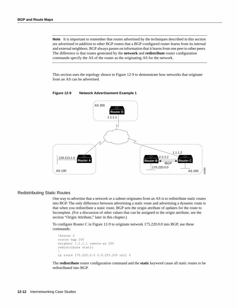
This section uses the topology shown in Figure 12-9 to demonstrate how networks that originatefrom an AS can be advertised.
Figure 12-9 Network Advertisement Example 1
Redistributing Static RoutesOne way to advertise that a network or a subnet originates from an AS is to redistribute static routesinto BGP. The only difference between advertising a static route and advertising a dynamic route isthat when you redistribute a static route, BGP sets the origin attribute of updates for the route toIncomplete. (For a discussion of other values that can be assigned to the origin attribute, see thesection “Origin Attribute,” later in this chapter.)
To configure Router C in Figure 12-9 to originate network 175.220.0.0 into BGP, use thesecommands:
!Router Crouter bgp 200neighbor 1.1.1.1 remote-as 300redistribute static!ip route 175.220.0.0 0.0.255.255 null 0
Theredistribute router configuration command and thestatic keyword cause all static routes to beredistributed into BGP.
AS 200
S45
80
175.220.0.0
129.213.1.0
1.1.1.1
1.1.1.22.2.2.2
IBGP
AS 100
Router B Router CRouter A
AS 300
Router D
Using the Border Gateway Protocol for Interdomain Routing 12-13
BGP and Route Maps
The ip route global configuration command establishes a static route for network 175.220.0.0. Intheory, the specification of the null 0 interface would cause a packet destined for network175.220.0.0 to be discarded. In practice, there will be a more specific match for the packet than175.220.0.0, and the router will send it out the appropriate interface. Redistributing a static route isthe best way to advertise a supernet because it prevents the route from flapping.
Note Regardless of route type (static or dynamic), theredistribute router configuration commandis the only way to inject BGP routes into an IGP.
Redistributing Dynamic RoutesAnother way to advertise networks is to redistribute dynamic routes. Typically, you redistribute IGProutes (such as Enhanced IGRP, IGRP, IS-IS, OSPF, and RIP routes) into BGP. Some of your IGProutes might have been learned from BGP, so you need to use access lists to prevent the redistributionof routes back into BGP.
Assume that in Figure 12-9 Routers B and C are running IBGP, that Router C is learning 129.213.1.0via BGP, and that Router B is redistributing 129.213.1.0 back into Enhanced IGRP. The followingcommands configure Router C:
!Router Crouter eigrp 10network 175.220.0.0redistribute bgp 200redistributed connecteddefault-metric 1000 100 250 100 1500!router bgp 200neighbor 1.1.1.1 remote-as 300neighbor 2.2.2.2 remote-as 200neighbor 1.1.1.1 distribute-list 1 outredistribute eigrp 10!access-list 1 permit 175.220.0.0 0.0.255.255
Theredistribute router configuration command with theeigrp keyword redistributes EnhancedIGRP routes for process ID 10 into BGP. (Normally, distributing BGP into IGP should be avoidedbecause too many routes would be injected into the AS.) Theneighbor distribute-list routerconfiguration command applies access list 1 to outgoing advertisements to the neighbor whose IPaddress is 1.1.1.1 (that is, Router D). Access list 1 specifies that network 175.220.0.0 is to beadvertised. All other networks, such as network 129.213.1.0, are implicitly prevented from beingadvertised. The access list prevents network 129.213.1.0 from being injected back into BGP as if itoriginated from AS 200, and allows BGP to advertise network 175.220.0.0 as originating fromAS 200.
Note Redistribution of dynamic routes requires careful use of access lists to prevent updates frombeing injected back into BGP. If possible, you should use thenetwork command (described in thesection “Using the network Command,” later in this chapter) or redistribute static routes instead ofredistributing dynamic routes.
12-14 Internetworking Case Studies
BGP and Route Maps
Using the network CommandAnother way to advertise networks is to use thenetwork router configuration command. When usedwith BGP, thenetwork command specifies the networks that the AS originates. (By way of contrast,when used with an IGP such as RIP, thenetwork command identifies the interfaces on which theIGP is to run.) Thenetwork command works for networks that the router learns dynamically or thatare configured as static routes. The origin attribute of routes that are injected into BGP by means ofthenetwork command is set to IGP.
The following commands configure Router C to advertise network 175.220.0.0:
!Router Crouter bgp 200neighbor 1.1.1.1 remote-as 300network 175.220.0.0
Thenetwork router configuration command causes Router C to generate an entry in the BGProuting table for network 175.220.0.0.
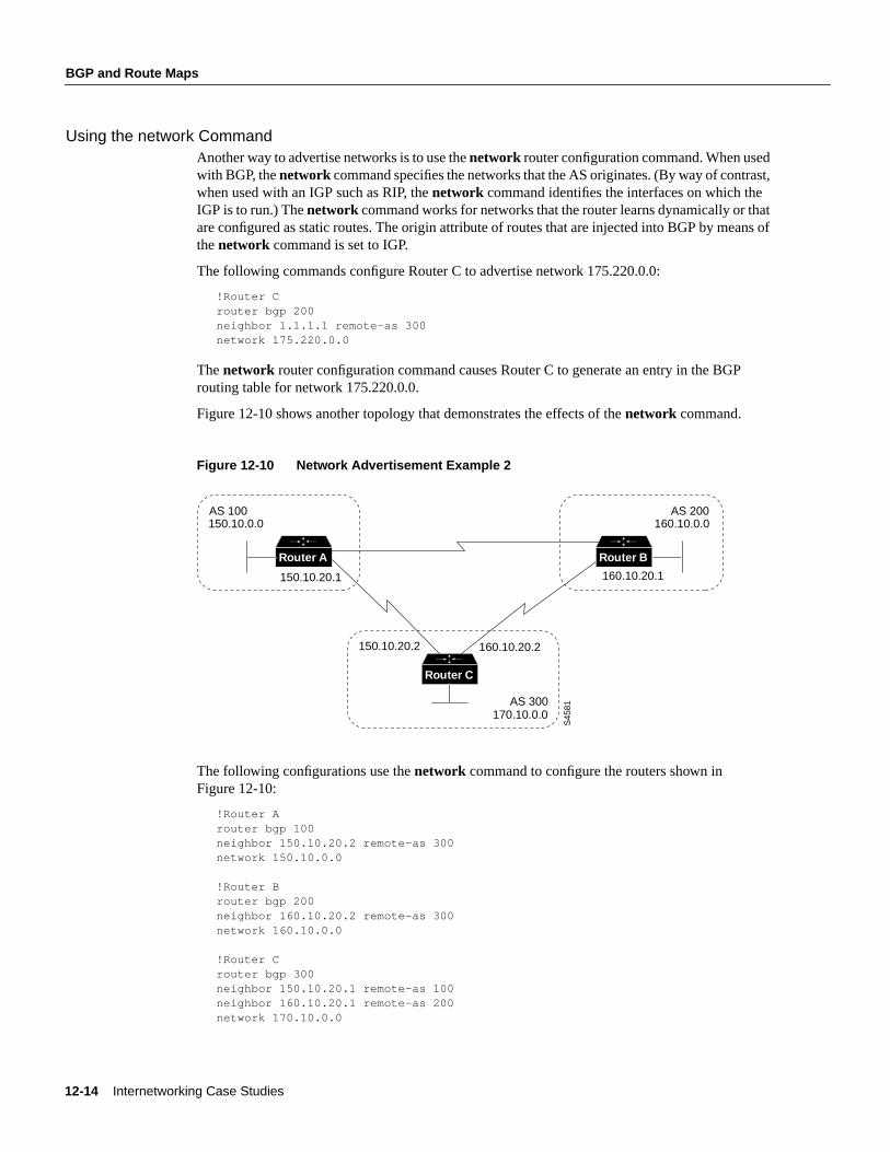
Figure 12-10 shows another topology that demonstrates the effects of thenetwork command.
Figure 12-10 Network Advertisement Example 2
The following configurations use thenetwork command to configure the routers shown inFigure 12-10:
!Router Arouter bgp 100neighbor 150.10.20.2 remote-as 300network 150.10.0.0
!Router Brouter bgp 200neighbor 160.10.20.2 remote-as 300network 160.10.0.0
!Router Crouter bgp 300neighbor 150.10.20.1 remote-as 100neighbor 160.10.20.1 remote-as 200network 170.10.0.0
AS 300
S45
81
170.10.0.0
AS 100150.10.0.0
150.10.20.1
150.10.20.2 160.10.20.2
Router C
Router A
AS 200160.10.0.0
160.10.20.1
Router B
Using the Border Gateway Protocol for Interdomain Routing 12-15
BGP Decision Algorithm
To ensure a loop-free interdomain topology, BGP does not accept updates that originated from itsown AS. For example, in Figure 12-10, if Router A generates an update for network 150.10.0.0 withthe origin set to AS 100 and sends it to Router C, Router C will pass the update to Router B with theorigin still set to AS 100. Router B will send the update (with the origin still set to AS 100) toRouter A, which will recognize that the update originated from its own AS and will ignore it.
BGP Decision AlgorithmWhen a BGP speaker receives updates from multiple ASs that describe different paths to the samedestination, it must choose the single best path for reaching that destination. Once chosen, BGPpropagates the best path to its neighbors. The decision is based on the value of attributes (such asnext hop, administrative weights, local preference, the origin of the route, and path length) that theupdate contains and other BGP-configurable factors. This section describes the following attributesand factors that BGP uses in the decision-making process:
• AS_path Attribute
• Origin Attribute
• Next Hop Attribute
• Weight Attribute
• Local Preference Attribute
• Multi-Exit Discriminator Attribute
• Community Attribute
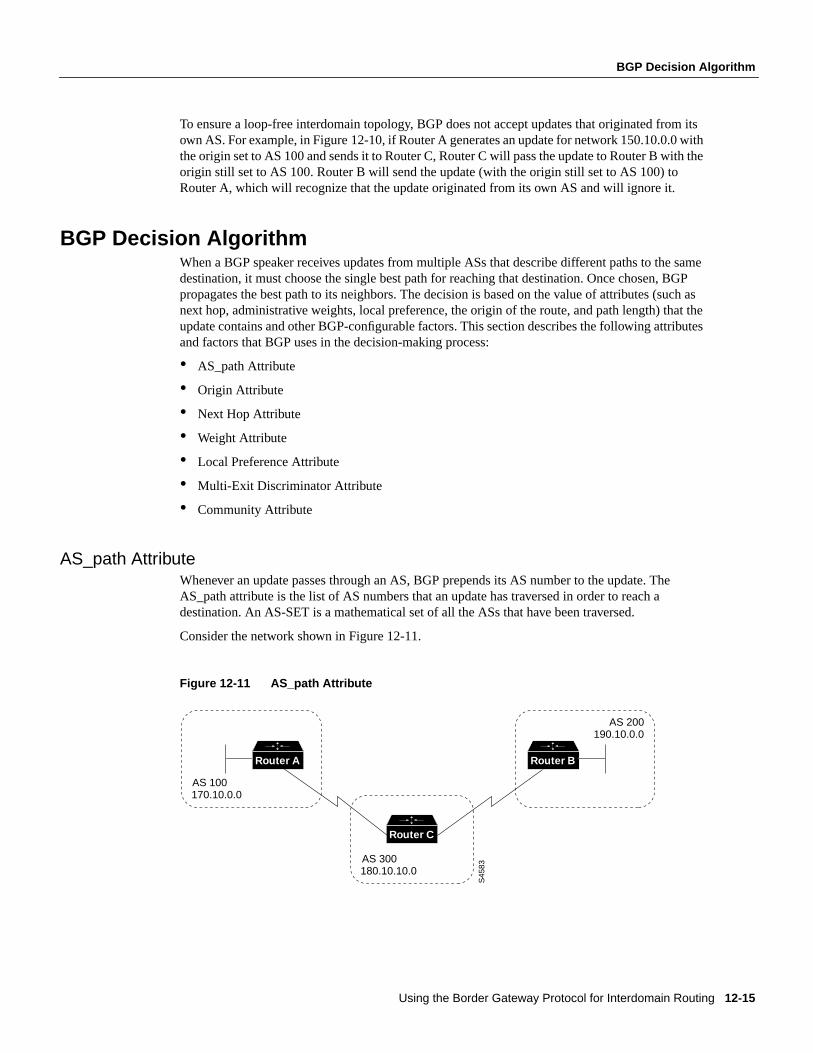
AS_path AttributeWhenever an update passes through an AS, BGP prepends its AS number to the update. TheAS_path attribute is the list of AS numbers that an update has traversed in order to reach adestination. An AS-SET is a mathematical set of all the ASs that have been traversed.
Consider the network shown in Figure 12-11.
Figure 12-11 AS_path Attribute
AS 300
S45
83180.10.10.0
AS 100170.10.0.0
Router C
Router A
AS 200190.10.0.0
Router B
12-16 Internetworking Case Studies
BGP Decision Algorithm
In Figure 12-11, Router B advertises network 190.10.0.0 in AS 200 with an AS_path of 200. Whenthe update for 190.10.0.0 traverses AS 300, Router C prepends its own AS number to it, so when theupdate reaches Router A, two AS numbers have been attached to it: 200 and then 300. That is, theAS_path attribute for reaching network 190.10.0.0 from Router A is 300, 200. Likewise, theAS_path attribute for reaching network 170.10.0.0 from Router B is 300, 100.
Origin AttributeThe origin attribute provides information about the origin of the route. The origin of a route can beone of three values:
• IGP—The route is interior to the originating AS. This value is set when thenetwork routerconfiguration command is used to inject the route into BGP. The IGP origin type is representedby the letter i in the output of theshow ip bgp EXEC command.
• EGP—The route is learned via the Exterior Gateway Protocol (EGP). The EGP origin type isrepresented by the letter e in the output of theshow ip bgp EXEC command.
• Incomplete—The origin of the route is unknown or learned in some other way. An origin ofIncomplete occurs when a route is redistributed into BGP. The Incomplete origin type isrepresented by the ? symbol in the output of theshow ip bgp EXEC command.
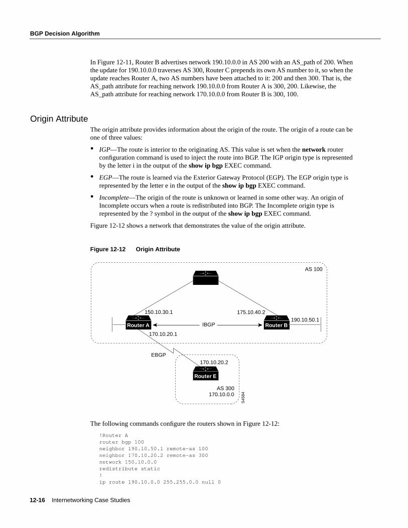
Figure 12-12 shows a network that demonstrates the value of the origin attribute.
Figure 12-12 Origin Attribute
The following commands configure the routers shown in Figure 12-12:
!Router Arouter bgp 100neighbor 190.10.50.1 remote-as 100neighbor 170.10.20.2 remote-as 300network 150.10.0.0redistribute static!ip route 190.10.0.0 255.255.0.0 null 0
AS 300
S45
84170.10.0.0
IBGP
EBGP
170.10.20.1
175.10.40.2
170.10.20.2
150.10.30.1
Router E
Router A
AS 100
190.10.50.1Router B
Using the Border Gateway Protocol for Interdomain Routing 12-17
BGP Decision Algorithm
!Router Brouter bgp 100neighbor 150.10.30.1 remote-as 100network 190.10.50.0
!Router Erouter bgp 300neighbor 170.10.20.1 remote-as 100network 170.10.0.0
Given these configurations, the following is true:
• From Router A, the route for reaching 170.10.0.0 has an AS_path of 300 and an origin attributeof IGP.
• From Router A, the route for reaching 190.10.50.0 has an empty AS_path (the route is in thesame AS as Router A) and an origin attribute of IGP.
• From Router E, the route for reaching 150.10.0.0 has an AS_path of 100 and an origin attributeof IGP.
• From Router E, the route for reaching 190.10.0.0 has an AS_path of 100 and an origin attributeof Incomplete (because 190.10.0.0 is a redistributed route).
Next Hop AttributeThe BGP next hop attribute is the IP address of the next hop that is going to be used to reach a certaindestination.
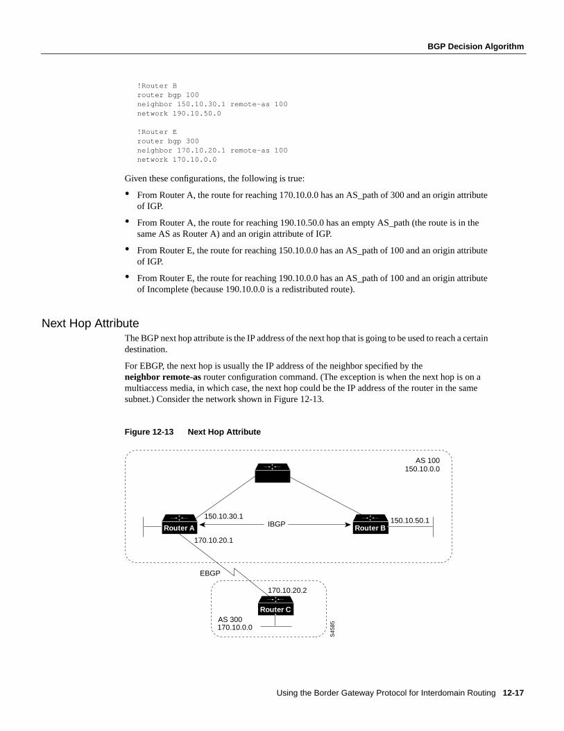
For EBGP, the next hop is usually the IP address of the neighbor specified by theneighbor remote-as router configuration command. (The exception is when the next hop is on amultiaccess media, in which case, the next hop could be the IP address of the router in the samesubnet.) Consider the network shown in Figure 12-13.
Figure 12-13 Next Hop Attribute
AS 300
AS 100
S45
85170.10.0.0
IBGP
EBGP
170.10.20.1
170.10.20.2
150.10.30.1
150.10.0.0
Router C
Router A150.10.50.1
Router B
12-18 Internetworking Case Studies
BGP Decision Algorithm
In Figure 12-13, Router C advertises network 170.10.0.0 to Router A with a next hop attribute of170.10.20.2, and Router A advertises network 150.10.0.0 to Router C with a next hop attribute of170.10.20.1.
BGP specifies that the next hop of EBGP-learned routes should be carried without modification intoIBGP. Because of that rule, Router A advertises 170.10.0.0 to its IBGP peer (Router B) with a nexthop attribute of 170.10.20.2. As a result, according to Router B, the next hop to reach 170.10.0.0 is170.10.20.2, instead of 150.10.30.1. For that reason, the configuration must ensure that Router B canreach 170.10.20.2 via an IGP. Otherwise, Router B will drop packets destined for 170.10.0.0 becausethe next hop address is inaccessible.
For example, if Router B runs IGRP, Router A should run IGRP on network 170.10.0.0. You mightwant to make IGRP passive on the link to Router C so that only BGP updates are exchanged.
The following commands configure the routers shown in Figure 12-13:
!Router Arouter bgp 100neighbor 170.10.20.2 remote-as 300neighbor 150.10.50.1 remote-as 100network 150.10.0.0
!Router Brouter bgp 100neighbor 150.10.30.1 remote-as 100
!Router Crouter bgp 300neighbor 170.10.20.1 remote-as 100network 170.10.0.0
Note Router C advertises 170.10.0.0 to Router A with a next hop attribute of 170.10.20.2, andRouter A advertises 170.10.0.0 to Router B with a next hop attribute of 170.10.20.2. The next hopof EBGP-learned routes is passed to the IBGP neighbor.
Next Hop Attribute and Multiaccess MediaBGP might set the value of the next hop attribute differently on multiaccess media, such as Ethernet.Consider the network shown in Figure 12-14.
Using the Border Gateway Protocol for Interdomain Routing 12-19
BGP Decision Algorithm
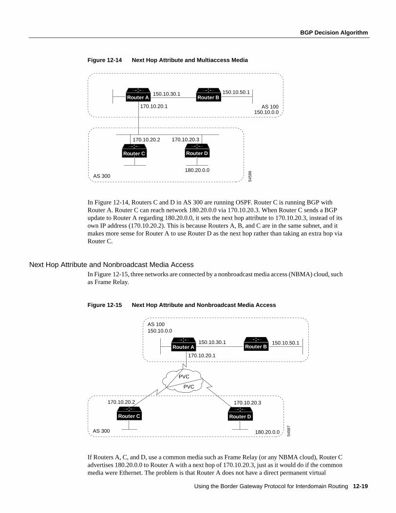
Figure 12-14 Next Hop Attribute and Multiaccess Media
In Figure 12-14, Routers C and D in AS 300 are running OSPF. Router C is running BGP withRouter A. Router C can reach network 180.20.0.0 via 170.10.20.3. When Router C sends a BGPupdate to Router A regarding 180.20.0.0, it sets the next hop attribute to 170.10.20.3, instead of itsown IP address (170.10.20.2). This is because Routers A, B, and C are in the same subnet, and itmakes more sense for Router A to use Router D as the next hop rather than taking an extra hop viaRouter C.
Next Hop Attribute and Nonbroadcast Media AccessIn Figure 12-15, three networks are connected by a nonbroadcast media access (NBMA) cloud, suchas Frame Relay.
Figure 12-15 Next Hop Attribute and Nonbroadcast Media Access
If Routers A, C, and D, use a common media such as Frame Relay (or any NBMA cloud), Router Cadvertises 180.20.0.0 to Router A with a next hop of 170.10.20.3, just as it would do if the commonmedia were Ethernet. The problem is that Router A does not have a direct permanent virtual
AS 300
AS 100150.10.0.0
S45
86
180.20.0.0
170.10.20.2
150.10.30.1
170.10.20.1
Router C
Router A
170.10.20.3
Router D
150.10.50.1Router B
S45
87
180.20.0.0
170.10.20.3170.10.20.2
AS 100150.10.0.0
AS 300
PVC
PVC
Router DRouter C
150.10.50.1
170.10.20.1
150.10.30.1Router BRouter A
12-20 Internetworking Case Studies
BGP Decision Algorithm
connection (PVC) to Router D and cannot reach the next hop, so routing will fail. To remedy thissituation, use theneighbor next-hop-selfrouter configuration command, as shown in the followingconfiguration for Router C:
!Router Crouter bgp 300neighbor 170.10.20.1 remote-as 100neighbor 170.10.20.1 next-hop-self
Theneighbor next-hop-self command causes Router C to advertise 180.20.0.0 with the next hopattribute set to 170.10.20.2.
Weight AttributeThe weight attribute is a special Cisco attribute that is used in the path selection process when thereis more than one route to the same destination. The weight attribute is local to the router on whichit is assigned, and it is not propagated in routing updates. By default, the weight attribute is 32768for paths that the router originates and zero for other paths. Routes with a higher weight are preferredwhen there are multiple routes to the same destination.
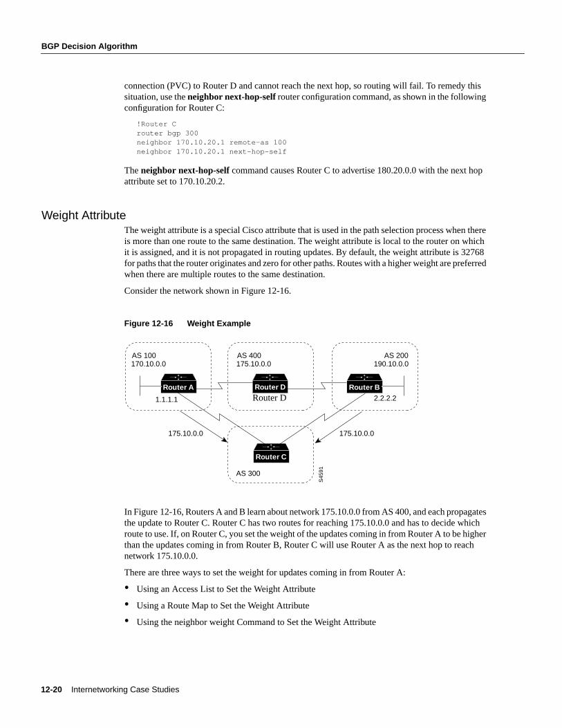
Consider the network shown in Figure 12-16.
Figure 12-16 Weight Example
In Figure 12-16, Routers A and B learn about network 175.10.0.0 from AS 400, and each propagatesthe update to Router C. Router C has two routes for reaching 175.10.0.0 and has to decide whichroute to use. If, on Router C, you set the weight of the updates coming in from Router A to be higherthan the updates coming in from Router B, Router C will use Router A as the next hop to reachnetwork 175.10.0.0.
There are three ways to set the weight for updates coming in from Router A:
• Using an Access List to Set the Weight Attribute
• Using a Route Map to Set the Weight Attribute
• Using the neighbor weight Command to Set the Weight Attribute
AS 300
S45
91
AS 100170.10.0.0
AS 400175.10.0.0
175.10.0.0 175.10.0.0
AS 200190.10.0.0
1.1.1.1 2.2.2.2
Router C
Router A Router BRouter D
Router D
Using the Border Gateway Protocol for Interdomain Routing 12-21
BGP Decision Algorithm
Using an Access List to Set the Weight AttributeThe following commands on Router C use access lists and the value of the AS_path attribute toassign a weight to route updates:
!Router Crouter bgp 300neighbor 1.1.1.1 remote-as 100neighbor 1.1.1.1 filter-list 5 weight 2000neighbor 2.2.2.2 remote-as 200neighbor 2.2.2.2 filter-list 6 weight 1000!ip as-path access-list 5 permit ^100$ip as-path access-list 6 permit ^200$
In this example, 2000 is assigned to the weight attribute of updates from the neighbor at IP address1.1.1.1 that are permitted by access list 5. Access list 5 permits updates whose AS_path attributestarts with 100 (as specified by ^) and ends with 100 (as specified by $). (The ^ and $ symbols areused to form regular expressions. For a complete explanation of regular expressions, see theappendix on regular expressions in the Cisco Internetwork Operating System (Cisco IOS) softwareconfiguration guides and command references.
This example also assigns 1000 to the weight attribute of updates from the neighbor at IP address2.2.2.2 that are permitted by access list 6. Access list 6 permits updates whose AS_path attributestarts with 200 and ends with 200.
In effect, this configuration assigns 2000 to the weight attribute of all route updates received fromAS 100 and assigns 1000 to the weight attribute of all route updates from AS 200.
Using a Route Map to Set the Weight AttributeThe following commands on Router C use a route map to assign a weight to route updates:
!Router Crouter bgp 300neighbor 1.1.1.1 remote-as 100neighbor 1.1.1.1 route-map SETWEIGHTIN inneighbor 2.2.2.2 remote-as 200neighbor 2.2.2.2 route-map SETWEIGHTIN in!ip as-path access-list 5 permit ^100$!route-map SETWEIGHTIN permit 10match as-path 5set weight 2000route-map SETWEIGHTIN permit 20set weight 1000
This first instance of the SETWEIGHTIN route map assigns 2000 to any route update from AS 100,and the second instance of the SETWEIGHTIN route map assigns 1000 to route updates from anyother AS.
Using the neighbor weight Command to Set the Weight AttributeThe following configuration for Router C uses theneighbor weight router configuration command:
!Router Crouter bgp 300neighbor 1.1.1.1 remote-as 100neighbor 1.1.1.1 weight 2000neighbor 2.2.2.2 remote-as 200neighbor 2.2.2.2 weight 1000
12-22 Internetworking Case Studies
BGP Decision Algorithm
This configuration sets the weight of all route updates from AS 100 to 2000, and the weight of allroute updates coming from AS 200 to 1000. The higher weight assigned to route updates fromAS 100 causes Router C to send traffic through Router A.
Local Preference AttributeWhen there are multiple paths to the same destination, the local preference attribute indicates thepreferred path. The path with the higher preference is preferred (the default value of the localpreference attribute is 100). Unlike the weight attribute, which is only relevant to the local router,the local preference attribute is part of the routing update and is exchanged among routers in thesame AS.
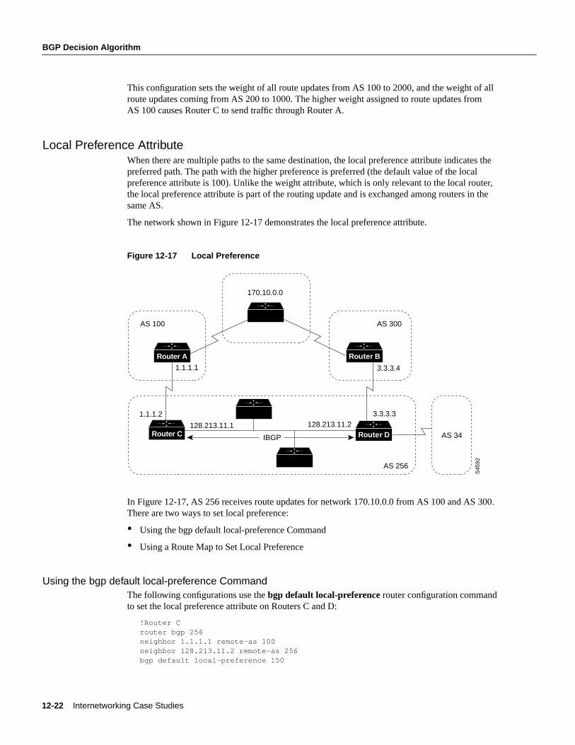
The network shown in Figure 12-17 demonstrates the local preference attribute.
Figure 12-17 Local Preference
In Figure 12-17, AS 256 receives route updates for network 170.10.0.0 from AS 100 and AS 300.There are two ways to set local preference:
• Using the bgp default local-preference Command
• Using a Route Map to Set Local Preference
Using the bgp default local-preference CommandThe following configurations use thebgp default local-preferencerouter configuration commandto set the local preference attribute on Routers C and D:
!Router Crouter bgp 256neighbor 1.1.1.1 remote-as 100neighbor 128.213.11.2 remote-as 256bgp default local-preference 150
S45
92
AS 100
170.10.0.0
128.213.11.1 128.213.11.2
AS 300
3.3.3.3
1.1.1.1 3.3.3.4
AS 256
1.1.1.2
Router C
Router A Router B
Router D AS 34IBGP
Using the Border Gateway Protocol for Interdomain Routing 12-23
BGP Decision Algorithm
!Router Drouter bgp 256neighbor 3.3.3.4 remote-as 300neighbor 128.213.11.1 remote-as 256bgp default local-preference 200
The configuration for Router C causes it to set the local preference of all updates from AS 300to 150, and the configuration for Router D causes it to set the local preference for all updates fromAS 100 to 200. Because local preference is exchanged within the AS, both Routers C and Ddetermine that updates regarding network 170.10.0.0 have a higher local preference when they comefrom AS 300 than when they come from AS 100. As a result, all traffic in AS 256 destined fornetwork 170.10.0.0 is sent to Router D as the exit point.
Using a Route Map to Set Local PreferenceRoute maps provide more flexibility than thebgp default local-preference router configurationcommand. When thebgp default local-preferencecommand is used on Router D in Figure 12-17,the local preference attribute of all updates received by Router D will be set to 200, including updatesfrom AS 34.
The following configuration uses a route map to set the local preference attribute on Router Dspecifically for updates regarding AS 300:
!Router Drouter bgp 256neighbor 3.3.3.4 remote-as 300route-map SETLOCALIN inneighbor 128.213.11.1 remote-as 256!ip as-path 7 permit ^300$route-map SETLOCALIN permit 10match as-path 7set local-preference 200!route-map SETLOCALIN permit 20
With this configuration, the local preference attribute of any update coming from AS 300 is setto 200. Instance 20 of the SETLOCALIN route map accepts all other routes.
Multi-Exit Discriminator AttributeThe multi-exit discriminator (MED) attribute is a hint to external neighbors about the preferred pathinto an AS when there are multiple entry points into the AS. A lower MED value is preferred over ahigher MED value. The default value of the MED attribute is 0.
Note In BGP Version 3, MED is known as Inter-AS_Metric.
Unlike local preference, the MED attribute is exchanged between ASs, but a MED attribute thatcomes into an AS does not leave the AS. When an update enters the AS with a certain MED value,that value is used for decision making within the AS. When BGP sends that update to another AS,the MED is reset to 0.
Unless otherwise specified, the router compares MED attributes for paths from external neighborsthat are in the same AS. If you want MED attributes from neighbors in other ASs to be compared,you must configure thebgp always-compare-med command.
12-24 Internetworking Case Studies
BGP Decision Algorithm
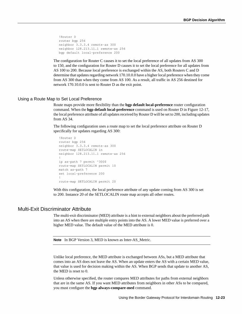
The network shown in Figure 12-18 demonstrates the use of the MED attribute.
Figure 12-18 MED Example
In Figure 12-18, AS 100 receives updates regarding network 180.10.0.0 from Routers B, C, and D.Routers C and D are in AS 300, and Router B is in AS 400.
The following commands configure Routers A, B, C, and D:
!Router Arouter bgp 100neighbor 2.2.2.1 remote-as 300neighbor 3.3.3.3 remote-as 300neighbor 4.4.4.3 remote-as 400
!Router Brouter bgp 400neighbor 4.4.4.4 remote-as 100neighbor 4.4.4.4 route-map SETMEDOUT outneighbor 5.5.5.4 remote-as 300!route-map SETMEDOUT permit 10set metric 50
!Router Crouter bgp 300neighbor 2.2.2.2 remote-as 100neighbor 2.2.2.2 route-map SETMEDOUT outneighbor 5.5.5.5 remote-as 400neighbor 1.1.1.2 remote-as 300!route-map SETMEDOUT permit 10set metric 120
!Router Drouter bgp 300neighbor 3.3.3.2 remote-as 100neighbor 3.3.3.2 route map SETMEDOUT outneighbor 1.1.1.1 remote-as 300route-map SETMEDOUT permit 10set metric 200
S45
93
3.3.3.3
3.3.3.22.2.2.2
2.2.2.1
1.1.1.1
180.10.0.0MED = 120
180.10.0.0MED = 200
180.10.0.0MED = 50
5.5.5.4
5.5.5.5
4.4.4.44.4.4.3
1.1.1.2AS 300
180.10.0.0
AS 100170.10.0.0
AS 400
Router C
Router A Router B
Router D
Using the Border Gateway Protocol for Interdomain Routing 12-25
BGP Decision Algorithm
By default, BGP compares the MED attributes of routes coming from neighbors in the same externalAS (such as AS 300 in Figure 12-18). Router A can only compare the MED attribute coming fromRouter C (120) to the MED attribute coming from Router D (200) even though the update comingfrom Router B has the lowest MED value.
Router A will choose Router C as the best path for reaching network 180.10.0.0. To force Router Ato include updates for network 180.10.0.0 from Router B in the comparison, use thebgp always-compare-med router configuration command, as in the following modifiedconfiguration for Router A:
!Router Arouter bgp 100neighbor 2.2.2.1 remote-as 300neighbor 3.3.3.3 remote-as 300neighbor 4.4.4.3 remote-as 400bgp always-compare-med
Router A will choose Router B as the best next hop for reaching network 180.10.0.0 (assuming thatall other attributes are the same).
You can also set the MED attribute when you configure the redistribution of routes into BGP. Forexample, on Router B you can inject the static route into BGP with a MED of 50 as in the followingconfiguration:
!Router Brouter bgp 400redistribute staticdefault-metric 50!ip route 160.10.0.0 255.255.0.0 null 0
The preceding configuration causes Router B to send out updates for 160.10.0.0 with a MEDattribute of 50.
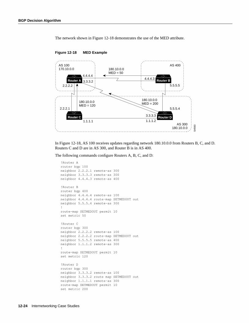
Community AttributeThe community attribute provides a way of grouping destinations (calledcommunities) to whichrouting decisions (such as acceptance, preference, and redistribution) can be applied.
Route maps are used to set the community attribute. A few predefined communities are listed inTable 12-1.
Table 12-1 Predefined Communities
The following route maps set the value of the community attribute:
route-map COMMUNITYMAPmatch ip address 1set community no-advertise!route-map SETCOMMUNITYmatch as-path 1set community 200 additive
Community Meaning
no-export Do not advertise this route to EBGP peers.
no-advertise Do not advertise this route to any peer.
internet Advertise this route to the internet community; all routers in the network belong to it.
12-26 Internetworking Case Studies
Controlling the Flow of BGP Updates
If you specify theadditive keyword, the specified community value is added to the existing value ofthe community attribute. Otherwise, the specified community value replaces any community valuethat was set previously.
To send the community attribute to a neighbor, you must use theneighbor send-communityrouterconfiguration command, as in the following example:
router bgp 100neighbor 3.3.3.3 remote-as 300neighbor 3.3.3.3 send-communityneighbor 3.3.3.3 route-map setcommunity out
For examples of how the community attribute is used to filter updates, see the section “CommunityFiltering,” later in this chapter.
Summary of the BGP Path Selection ProcessBGP selects only one path as the best path. When the path is selected, BGP puts the selected path inits routing table and propagates the path to its neighbors. BGP uses the following criteria, in the orderpresented, to select a path for a destination:
1 If the path specifies a next hop that is inaccessible, drop the update.
2 Prefer the path with the largest weight.
3 If the weights are the same, prefer the path with the largest local preference.
4 If the local preferences are the same, prefer the path that was originated by BGP running on thisrouter.
5 If no route was originated, prefer the route that has the shortest AS_path.
6 If all paths have the same AS_path length, prefer the path with the lowest origin type (where IGPis lower than EGP, and EGP is lower than Incomplete).
7 If the origin codes are the same, prefer the path with the lowest MED attribute.
8 If the paths have the same MED, prefer the external path over the internal path.
9 If the paths are still the same, prefer the path through the closest IGP neighbor.
10 Prefer the path with the lowest IP address, as specified by the BGP router ID.
Controlling the Flow of BGP UpdatesThis section describes techniques for controlling the flow of BGP updates. The techniques includethe following:
• Administrative Distance
• BGP Filtering
• BGP Peer Groups
• CIDR and Aggregate Addresses
• Confederations
• Route Reflectors
• Route Flap Dampening
Using the Border Gateway Protocol for Interdomain Routing 12-27
Controlling the Flow of BGP Updates
Administrative DistanceNormally, a route could be learned via more than one protocol. Administrative distance is used todiscriminate between routes learned from more than one protocol. The route with the lowestadministrative distance is installed in the IP routing table. By default, BGP uses the administrativedistances shown in Table 12-2.
Table 12-2 BGP Default Distances
Note Distance does not influence the BGP path selection algorithm, but it does influence whetherBGP-learned routes are installed in the IP routing table.
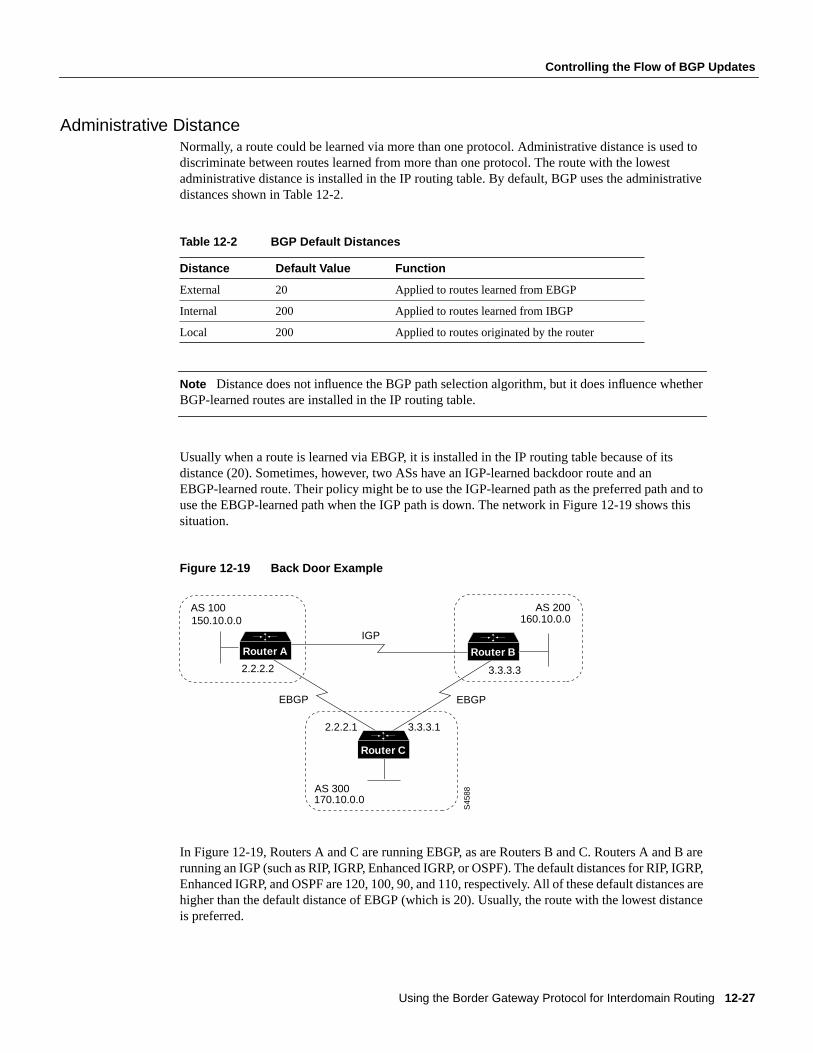
Usually when a route is learned via EBGP, it is installed in the IP routing table because of itsdistance (20). Sometimes, however, two ASs have an IGP-learned backdoor route and anEBGP-learned route. Their policy might be to use the IGP-learned path as the preferred path and touse the EBGP-learned path when the IGP path is down. The network in Figure 12-19 shows thissituation.
Figure 12-19 Back Door Example
In Figure 12-19, Routers A and C are running EBGP, as are Routers B and C. Routers A and B arerunning an IGP (such as RIP, IGRP, Enhanced IGRP, or OSPF). The default distances for RIP, IGRP,Enhanced IGRP, and OSPF are 120, 100, 90, and 110, respectively. All of these default distances arehigher than the default distance of EBGP (which is 20). Usually, the route with the lowest distanceis preferred.
Distance Default Value Function
External 20 Applied to routes learned from EBGP
Internal 200 Applied to routes learned from IBGP
Local 200 Applied to routes originated by the router
AS 200
S45
88
160.10.0.0
3.3.3.3
3.3.3.12.2.2.1
2.2.2.2
150.10.0.0
AS 300
AS 100
Router BRouter A
170.10.0.0
IGP
EBGP EBGP
Router C
12-28 Internetworking Case Studies
Controlling the Flow of BGP Updates
Router A receives updates about 160.10.0.0 from two routing protocols: EBGP and an IGP. Becausethe default distance for EBGP is lower than the default distance of the IGP, Router A will choose theEBGP-learned route from Router C. If you want Router A to learn about 160.10.0.0 from Router B(IGP), you could use one of the following techniques:
• Change the external distance of EBGP. (Not recommended because the distance will affect allupdates, which might lead to undesirable behavior when multiple routing protocols interact withone another.)
• Change the distance of the IGP. (Not recommended because the distance will affect all updates,which might lead to undesirable behavior when multiple routing protocols interact with oneanother.)
• Establish a BGP back door. (Recommended)
To establish a BGP back door, use thenetwork backdoor router configuration command.
The following commands configure Router A in Figure 12-19:
!Router Arouter eigrp 10network 150.10.0.0router bgp 100neighbor 2.2.2.1 remote-as 300network 160.10.0.0 backdoor
With thenetwork backdoor command, Router A treats the EBGP-learned route as local and installsit in the IP routing table with a distance of 200. The network is also learned via Enhanced IGRP (witha distance of 90), so the Enhanced IGRP route is successfully installed in the IP routing table and isused to forward traffic. If the Enhanced IGRP-learned route goes down, the EBGP-learned route willbe installed in the IP routing table and used to forward traffic.
Note Although BGP treats network 160.10.0.0 as a local entry, it does not advertise network160.10.0.0 as it normally would advertise a local entry.
BGP FilteringYou can control the sending and receiving of updates by using the following filtering methods:
• Prefix Filtering
• AS_path Filtering
• Route Map Filtering
• Community Filtering
Each method can be used to achieve the same result—the choice of method depends on the specificnetwork configuration.
Prefix FilteringTo restrict the routing information that the router learns or advertises, you can filter based on routingupdates to or from a particular neighbor. The filter consists of an access list that is applied to updatesto or from a neighbor.
The network shown in Figure 12-20 demonstrates the usefulness of prefix filtering.
Using the Border Gateway Protocol for Interdomain Routing 12-29
Controlling the Flow of BGP Updates
Figure 12-20 Route Filtering
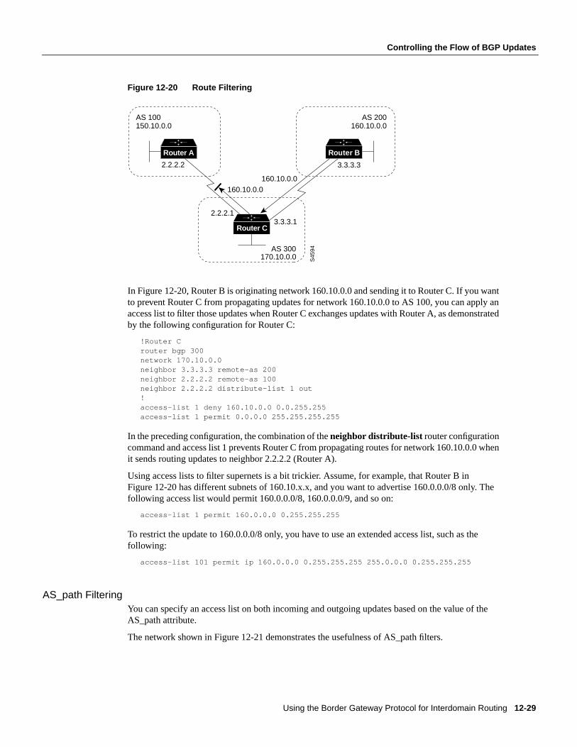
In Figure 12-20, Router B is originating network 160.10.0.0 and sending it to Router C. If you wantto prevent Router C from propagating updates for network 160.10.0.0 to AS 100, you can apply anaccess list to filter those updates when Router C exchanges updates with Router A, as demonstratedby the following configuration for Router C:
!Router Crouter bgp 300network 170.10.0.0neighbor 3.3.3.3 remote-as 200neighbor 2.2.2.2 remote-as 100neighbor 2.2.2.2 distribute-list 1 out!access-list 1 deny 160.10.0.0 0.0.255.255access-list 1 permit 0.0.0.0 255.255.255.255
In the preceding configuration, the combination of theneighbor distribute-list router configurationcommand and access list 1 prevents Router C from propagating routes for network 160.10.0.0 whenit sends routing updates to neighbor 2.2.2.2 (Router A).
Using access lists to filter supernets is a bit trickier. Assume, for example, that Router B inFigure 12-20 has different subnets of 160.10.x.x, and you want to advertise 160.0.0.0/8 only. Thefollowing access list would permit 160.0.0.0/8, 160.0.0.0/9, and so on:
access-list 1 permit 160.0.0.0 0.255.255.255
To restrict the update to 160.0.0.0/8 only, you have to use an extended access list, such as thefollowing:
access-list 101 permit ip 160.0.0.0 0.255.255.255 255.0.0.0 0.255.255.255
AS_path FilteringYou can specify an access list on both incoming and outgoing updates based on the value of theAS_path attribute.
The network shown in Figure 12-21 demonstrates the usefulness of AS_path filters.
S45
94
2.2.2.2
2.2.2.1
160.10.0.0160.10.0.0
170.10.0.0
3.3.3.1
3.3.3.3
AS 300
AS 100150.10.0.0
AS 200160.10.0.0
Router C
Router A Router B
12-30 Internetworking Case Studies
Controlling the Flow of BGP Updates
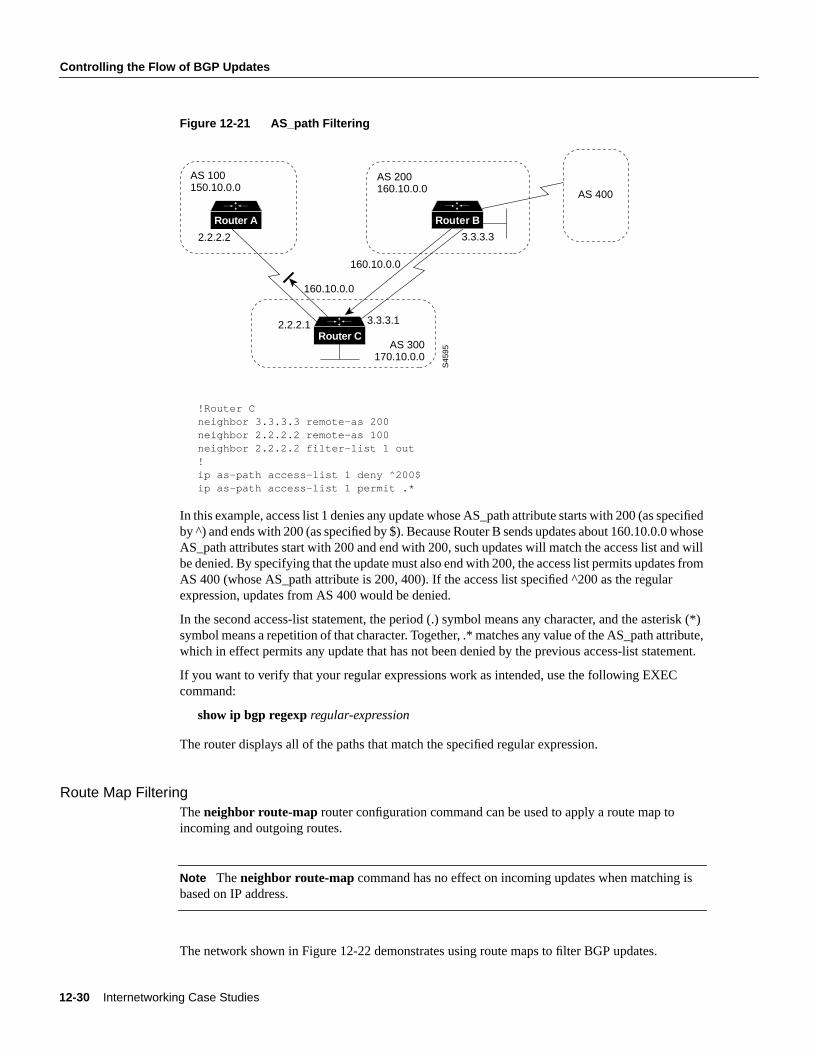
Figure 12-21 AS_path Filtering
!Router Cneighbor 3.3.3.3 remote-as 200neighbor 2.2.2.2 remote-as 100neighbor 2.2.2.2 filter-list 1 out!ip as-path access-list 1 deny ^200$ip as-path access-list 1 permit .*
In this example, access list 1 denies any update whose AS_path attribute starts with 200 (as specifiedby ^) and ends with 200 (as specified by $). Because Router B sends updates about 160.10.0.0 whoseAS_path attributes start with 200 and end with 200, such updates will match the access list and willbe denied. By specifying that the update must also end with 200, the access list permits updates fromAS 400 (whose AS_path attribute is 200, 400). If the access list specified ^200 as the regularexpression, updates from AS 400 would be denied.
In the second access-list statement, the period (.) symbol means any character, and the asterisk (*)symbol means a repetition of that character. Together, .* matches any value of the AS_path attribute,which in effect permits any update that has not been denied by the previous access-list statement.
If you want to verify that your regular expressions work as intended, use the following EXECcommand:
show ip bgp regexpregular-expression
The router displays all of the paths that match the specified regular expression.
Route Map FilteringTheneighbor route-map router configuration command can be used to apply a route map toincoming and outgoing routes.
Note Theneighbor route-map command has no effect on incoming updates when matching isbased on IP address.
The network shown in Figure 12-22 demonstrates using route maps to filter BGP updates.
S45
95
2.2.2.2
2.2.2.1 3.3.3.1
3.3.3.3
AS 400
AS 300170.10.0.0
AS 100150.10.0.0
AS 200160.10.0.0
Router C
Router A Router B
160.10.0.0
160.10.0.0
Using the Border Gateway Protocol for Interdomain Routing 12-31
Controlling the Flow of BGP Updates
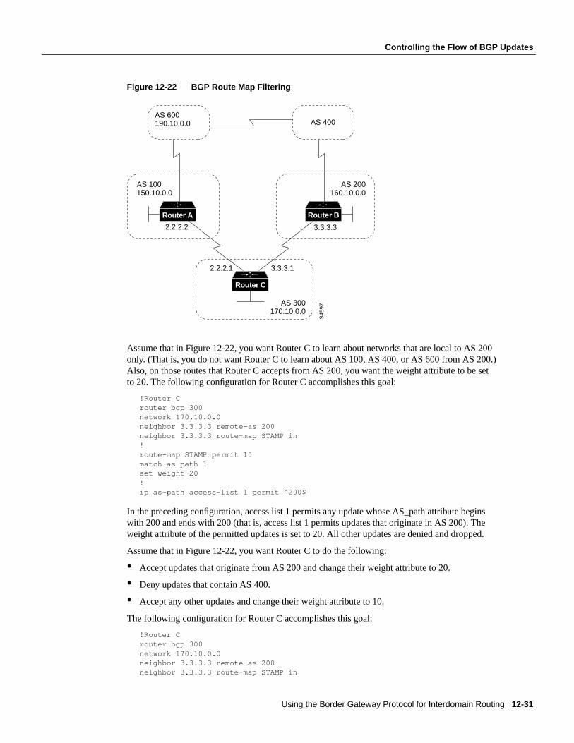
Figure 12-22 BGP Route Map Filtering
Assume that in Figure 12-22, you want Router C to learn about networks that are local to AS 200only. (That is, you do not want Router C to learn about AS 100, AS 400, or AS 600 from AS 200.)Also, on those routes that Router C accepts from AS 200, you want the weight attribute to be setto 20. The following configuration for Router C accomplishes this goal:
!Router Crouter bgp 300network 170.10.0.0neighbor 3.3.3.3 remote-as 200neighbor 3.3.3.3 route-map STAMP in!route-map STAMP permit 10match as-path 1set weight 20!ip as-path access-list 1 permit ^200$
In the preceding configuration, access list 1 permits any update whose AS_path attribute beginswith 200 and ends with 200 (that is, access list 1 permits updates that originate in AS 200). Theweight attribute of the permitted updates is set to 20. All other updates are denied and dropped.
Assume that in Figure 12-22, you want Router C to do the following:
• Accept updates that originate from AS 200 and change their weight attribute to 20.
• Deny updates that contain AS 400.
• Accept any other updates and change their weight attribute to 10.
The following configuration for Router C accomplishes this goal:
!Router Crouter bgp 300network 170.10.0.0neighbor 3.3.3.3 remote-as 200neighbor 3.3.3.3 route-map STAMP in
S45
97
2.2.2.2
2.2.2.1 3.3.3.1
3.3.3.3
AS 300170.10.0.0
AS 100150.10.0.0
AS 200160.10.0.0
Router C
Router A Router B
AS 600190.10.0.0 AS 400
12-32 Internetworking Case Studies
Controlling the Flow of BGP Updates
route-map STAMP permit 10match as-path 1set weight 20!route-map STAMP permit 20match as-path 2!route-map STAMP permit 30set weight 10!ip as-path access-list 1 permit ^200$ip as-path access-list 2 deny _400_
In the preceding configuration, access list 1 permits any update whose AS_path attribute beginswith 200 and ends with 200 (that is, access list 1 permits updates that originate in AS 200). Theweight attribute of the permitted updates is set to 20. Access list 2 denies updates whose AS_pathattribute contains 400. All other updates will have a weight of 10 (by means of instance 30 of theSTAMP route map) and will be permitted.
Suppose that in Figure 12-22 Router C advertises its own network (170.10.0.0) to AS 100 andAS 200. When updates about network 170.10.0.0 arrive in AS 600, the routers in AS 600 will havenetwork reachability information via two routes: via AS 100 with an AS_path attribute of (100, 300)and via AS 400 with an AS_path attribute of (400, 200, 300). Assuming that the values of all otherattributes are the same, the routers in AS 600 will pick the shortest AS_path attribute: the routethrough AS 100.
If you want to use the configuration of Router C to influence the choice of paths in AS 600, you cando so by prepending extra AS numbers to the AS_path attribute for routes that Router C advertisesto AS 100. A common practice is to repeat the AS number, as in the following configuration:
!Router Crouter bgp 300network 170.10.0.0neighbor 2.2.2.2 remote-as 100neighbor 2.2.2.2 route-map SETPATH out!route-map SETPATH permit 10set as-path prepend 300 300
Theset as-path route map configuration command with theprepend keyword causes Router C toprepend 300 twice to the value of the AS_path attribute before it sends updates to the neighbor at IPaddress 2.2.2.2 (Router A). As a result, the AS_path attribute of updates for network 170.10.0.0 thatAS 600 receives via AS 100 will be 100, 300, 300, 300, which is longer than the value of the AS_pathattribute of updates for network 170.10.0.0 that AS 600 receives via AS 400 (400, 200, 300). AS 600will choose (400, 200, 300) as the better path.
Community FilteringThe network shown in Figure 12-23 demonstrates the usefulness of community filters.
Using the Border Gateway Protocol for Interdomain Routing 12-33
Controlling the Flow of BGP Updates
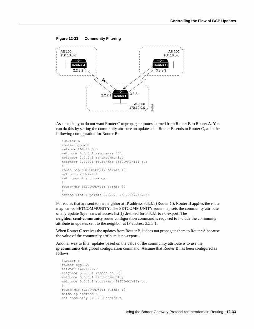
Figure 12-23 Community Filtering
Assume that you do not want Router C to propagate routes learned from Router B to Router A. Youcan do this by setting the community attribute on updates that Router B sends to Router C, as in thefollowing configuration for Router B:
!Router Brouter bgp 200network 160.10.0.0neighbor 3.3.3.1 remote-as 300neighbor 3.3.3.1 send-communityneighbor 3.3.3.1 route-map SETCOMMUNITY out!route-map SETCOMMUNITY permit 10match ip address 1set community no-export!route-map SETCOMMUNITY permit 20!access list 1 permit 0.0.0.0 255.255.255.255
For routes that are sent to the neighbor at IP address 3.3.3.1 (Router C), Router B applies the routemap named SETCOMMUNITY. The SETCOMMUNITY route map sets the community attributeof any update (by means of access list 1) destined for 3.3.3.1 to no-export. Theneighbor send-community router configuration command is required to include the communityattribute in updates sent to the neighbor at IP address 3.3.3.1.
When Router C receives the updates from Router B, it does not propagate them to Router A becausethe value of the community attribute is no-export.
Another way to filter updates based on the value of the community attribute is to use theip community-list global configuration command. Assume that Router B has been configured asfollows:
!Router Brouter bgp 200network 160.10.0.0neighbor 3.3.3.1 remote-as 300neighbor 3.3.3.1 send-communityneighbor 3.3.3.1 route-map SETCOMMUNITY out!route-map SETCOMMUNITY permit 10match ip address 2set community 100 200 additive
S45
96
2.2.2.2
2.2.2.1 3.3.3.1
3.3.3.3
AS 300170.10.0.0
AS 100150.10.0.0
AS 200160.10.0.0
Router C
Router A Router B
12-34 Internetworking Case Studies
Controlling the Flow of BGP Updates
route-map SETCOMMUNITY permit 20!access list 2 permit 0.0.0.0 255.255.255.255
In the preceding configuration, Router B adds 100 and 200 to the community value of any updatedestined for the neighbor at IP address 3.3.3.1. To configure Router C to use theip community-listglobal configuration command to set the value of the weight attribute based on whether thecommunity attribute contains 100 or 200, use the following configuration:
!Router Crouter bgp 300neighbor 3.3.3.3 remote-as 200neighbor 3.3.3.3 route-map check-community in!route-map check-community permit 10match community 1set weight 20!route-map check-community permit 20match community 2 exactset weight 10!route-map check-community permit 30match community 3!ip community-list 1 permit 100ip community-list 2 permit 200ip community-list 3 permit internet
In the preceding configuration, any route that has 100 in its community attribute matches communitylist 1 and has its weight set to 20. Any route whose community attribute is only 200 (by virtue of theexact keyword) matches community list 2 and has its weight set to 10. In the last community list(list 3) the use of theinternet keyword permits all other updates without changing the value of anattribute. (Theinternet keyword specifies all routes because all routes are members of the internetcommunity.)
BGP Peer GroupsA BGP peer group is a group of BGP neighbors that share the same update policies. Update policiesare usually set by route maps, distribution lists, and filter lists. Instead of defining the same policiesfor each individual neighbor, you define a peer group name and assign policies to the peer group.
Members of a peer group inherit all of the configuration options of the peer group. Peer groupmembers can also be configured to override configuration options if the options do not affectoutgoing updates. That is, you can only override options that are set for incoming updates.
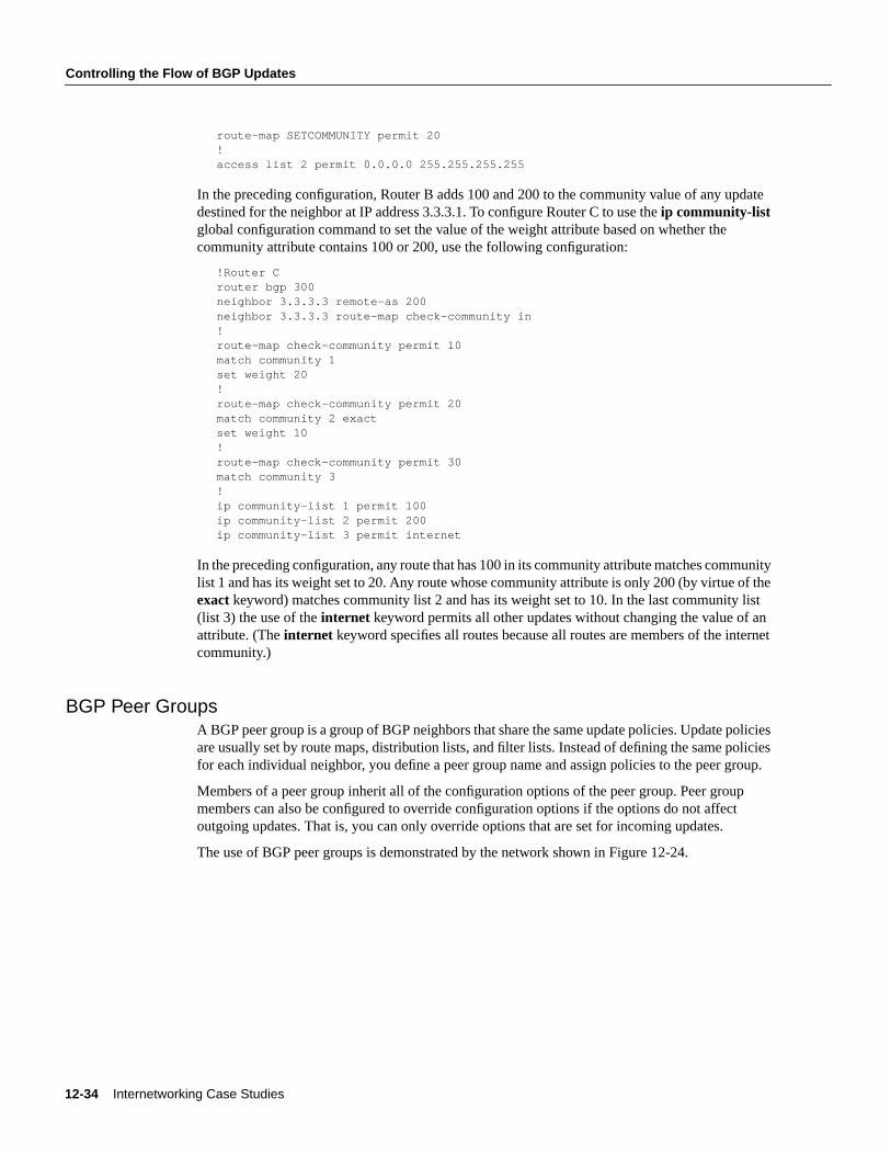
The use of BGP peer groups is demonstrated by the network shown in Figure 12-24.
Using the Border Gateway Protocol for Interdomain Routing 12-35
Controlling the Flow of BGP Updates
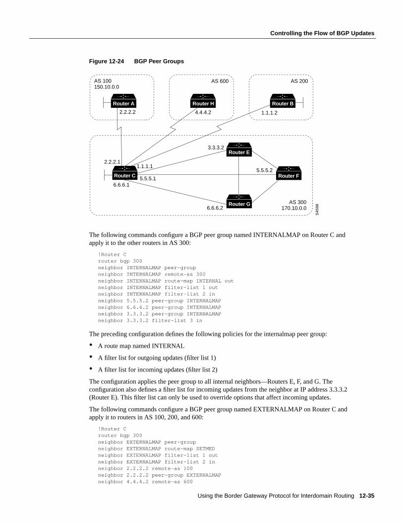
Figure 12-24 BGP Peer Groups
The following commands configure a BGP peer group named INTERNALMAP on Router C andapply it to the other routers in AS 300:
!Router Crouter bgp 300neighbor INTERNALMAP peer-groupneighbor INTERNALMAP remote-as 300neighbor INTERNALMAP route-map INTERNAL outneighbor INTERNALMAP filter-list 1 outneighbor INTERNALMAP filter-list 2 inneighbor 5.5.5.2 peer-group INTERNALMAPneighbor 6.6.6.2 peer-group INTERNALMAPneighbor 3.3.3.2 peer-group INTERNALMAPneighbor 3.3.3.2 filter-list 3 in
The preceding configuration defines the following policies for the internalmap peer group:
• A route map named INTERNAL
• A filter list for outgoing updates (filter list 1)
• A filter list for incoming updates (filter list 2)
The configuration applies the peer group to all internal neighbors—Routers E, F, and G. Theconfiguration also defines a filter list for incoming updates from the neighbor at IP address 3.3.3.2(Router E). This filter list can only be used to override options that affect incoming updates.
The following commands configure a BGP peer group named EXTERNALMAP on Router C andapply it to routers in AS 100, 200, and 600:
!Router Crouter bgp 300neighbor EXTERNALMAP peer-groupneighbor EXTERNALMAP route-map SETMEDneighbor EXTERNALMAP filter-list 1 outneighbor EXTERNALMAP filter-list 2 inneighbor 2.2.2.2 remote-as 100neighbor 2.2.2.2 peer-group EXTERNALMAPneighbor 4.4.4.2 remote-as 600
S45
98
6.6.6.1
6.6.6.2
AS 600 AS 200
5.5.5.2
3.3.3.2
1.1.1.24.4.4.22.2.2.2
1.1.1.12.2.2.1
5.5.5.1
AS 300170.10.0.0
AS 100150.10.0.0
Router E
Router G
Router A
Router FRouter C
Router H Router B
12-36 Internetworking Case Studies
Controlling the Flow of BGP Updates
neighbor 4.4.4.2 peer-group EXTERNALMAPneighbor 1.1.1.2 remote-as 200neighbor 1.1.1.2 peer-group EXTERNALMAPneighbor 1.1.1.2 filter-list 3 in
In the preceding configuration, theneighbor remote-asrouter configuration commands are placedoutside of theneighbor peer-grouprouter configuration commands because different external ASshave to be defined. Also note that this configuration defines filter list 3, which can be used to overrideconfiguration options for incoming updates from the neighbor at IP address 1.1.1.2 (Router B).
CIDR and Aggregate AddressesBGP4 supports classless interdomain routing (CIDR), which is a major improvement over BGP3.(CIDR is also known assupernetting.) CIDR is a new way of looking at IP addresses that eliminatesthe concept of classes (Class A, Class B, and so on). For example, network 192.213.0.0, which is anillegal Class C network number, is a legal supernet when it is represented in CIDR notation as192.213.0.0/16. The /16 indicates that the subnet mask consists of 16 bits (counting from the left).Therefore, 192.213.0.0/16 is similar to 192.213.0.0 255.255.0.0.
CIDR makes it easy to aggregate routes. Aggregation is the process of combining several differentroutes in such a way that a single route can be advertised, which minimizes the size of routing tables.
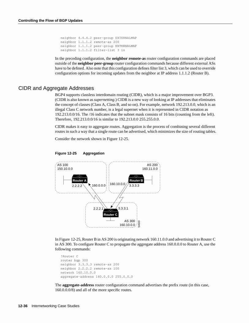
Consider the network shown in Figure 12-25.
Figure 12-25 Aggregation
In Figure 12-25, Router B in AS 200 is originating network 160.11.0.0 and advertising it to Router Cin AS 300. To configure Router C to propagate the aggregate address 160.0.0.0 to Router A, use thefollowing commands:
!Router Crouter bgp 300neighbor 3.3.3.3 remote-as 200neighbor 2.2.2.2 remote-as 100network 160.10.0.0aggregate-address 160.0.0.0 255.0.0.0
Theaggregate-address router configuration command advertises the prefix route (in this case,160.0.0.0/8) and all of the more specific routes.
Router A Router B
Router C
2.2.2.2 160.0.0.0 160.10.0.0 3.3.3.3
3.3.3.12.2.2.1
AS 100150.10.0.0
AS 200160.11.0.0
AS 300160.10.0.0
S46
00
Using the Border Gateway Protocol for Interdomain Routing 12-37
Controlling the Flow of BGP Updates
Note A router cannot aggregate an address if it does not have a more specific route of that addressin the BGP routing table. The more specific route can be injected in the BGP routing table byincoming updates from other ASs, can be redistributed from an IGP, or can be established by thenetwork router configuration command.
If you want Router C to propagate the prefix route only, and you do not want it to propagate a morespecific route, use the following command:
aggregate-address 160.0.0.0 255.0.0.0 summary-only
This command propagates the prefix (160.0.0.0/8) and suppresses any more specific routes that therouter may have in its BGP routing table.
Note If you use thenetwork command to advertise a network, the entry for that network is alwaysinjected into BGP updates, even if you specify thesummary-only keyword with theaggregate-address router configuration command.
If you want to suppress specific routes when aggregating routes, you can define a route map andapply it to the aggregate. If, for example, you want Router C in Figure 12-25 to aggregate 160.0.0.0and suppress the specific route 160.20.0.0, but propagate route 160.10.0.0, use the followingcommands:
!Router Crouter bgp 300neighbor 3.3.3.3 remote-as 200neighbor 2.2.2.2 remote-as 100network 160.10.0.0aggregate-address 160.0.0.0 255.0.0.0 suppress-map CHECK!route-map CHECK permit 10match ip address 1!access-list 1 deny 160.20.0.0 0.0.255.255access-list 1 permit 0.0.0.0 255.255.255.255
If you want the router to set the value of an attribute when it propagates the aggregate route, use anattribute map, as demonstrated by the following commands:
route-map SETORIGIN permit 10set origin igp!aggregate-address 160.0.0.0 255.0.0.0 attribute-map SETORIGIN
Aggregation and Static RoutesThe network shown in Figure 12-26 demonstrates how static routes can be used to generateaggregates.
12-38 Internetworking Case Studies
Controlling the Flow of BGP Updates
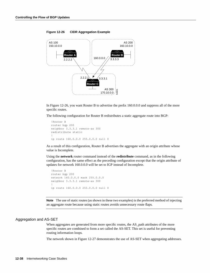
Figure 12-26 CIDR Aggregation Example
In Figure 12-26, you want Router B to advertise the prefix 160.0.0.0 and suppress all of the morespecific routes.
The following configuration for Router B redistributes a static aggregate route into BGP:
!Router Brouter bgp 200neighbor 3.3.3.1 remote-as 300redistribute static!ip route 160.0.0.0 255.0.0.0 null 0
As a result of this configuration, Router B advertises the aggregate with an origin attribute whosevalue is Incomplete.
Using thenetwork router command instead of theredistribute command, as in the followingconfiguration, has the same effect as the preceding configuration except that the origin attribute ofupdates for network 160.0.0.0 will be set to IGP instead of Incomplete.
!Router Brouter bgp 200network 160.0.0.0 mask 255.0.0.0neighbor 3.3.3.1 remote-as 300!ip route 160.0.0.0 255.0.0.0 null 0
Note The use of static routes (as shown in these two examples) is the preferred method of injectingan aggregate route because using static routes avoids unnecessary route flaps.
Aggregation and AS-SETWhen aggregates are generated from more specific routes, the AS_path attributes of the morespecific routes are combined to form a set called the AS-SET. This set is useful for preventingrouting information loops.
The network shown in Figure 12-27 demonstrates the use of AS-SET when aggregating addresses.
Router A Router B
Router C
2.2.2.2 3.3.3.3
3.3.3.12.2.2.1
AS 100150.10.0.0
AS 200160.10.0.0
AS 300170.10.0.0
S46
01
160.0.0.0
Using the Border Gateway Protocol for Interdomain Routing 12-39
Controlling the Flow of BGP Updates
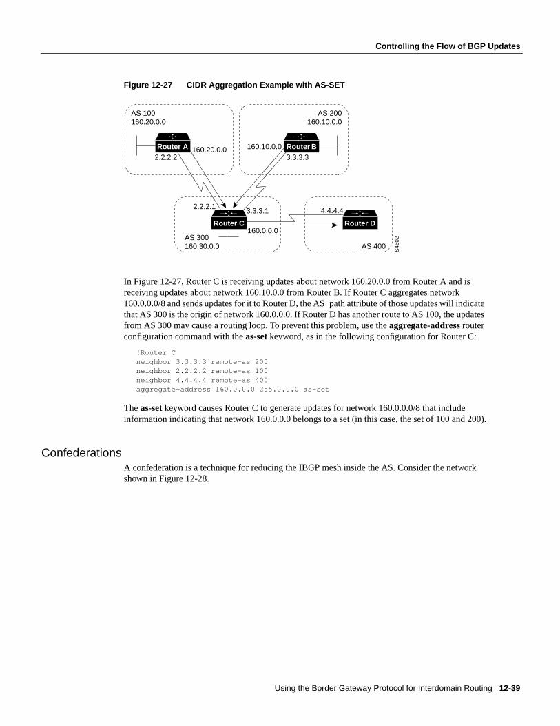
Figure 12-27 CIDR Aggregation Example with AS-SET
In Figure 12-27, Router C is receiving updates about network 160.20.0.0 from Router A and isreceiving updates about network 160.10.0.0 from Router B. If Router C aggregates network160.0.0.0/8 and sends updates for it to Router D, the AS_path attribute of those updates will indicatethat AS 300 is the origin of network 160.0.0.0. If Router D has another route to AS 100, the updatesfrom AS 300 may cause a routing loop. To prevent this problem, use theaggregate-addressrouterconfiguration command with theas-set keyword, as in the following configuration for Router C:
!Router Cneighbor 3.3.3.3 remote-as 200neighbor 2.2.2.2 remote-as 100neighbor 4.4.4.4 remote-as 400aggregate-address 160.0.0.0 255.0.0.0 as-set
Theas-set keyword causes Router C to generate updates for network 160.0.0.0/8 that includeinformation indicating that network 160.0.0.0 belongs to a set (in this case, the set of 100 and 200).
ConfederationsA confederation is a technique for reducing the IBGP mesh inside the AS. Consider the networkshown in Figure 12-28.
Router A Router B
Router C
2.2.2.2
160.10.0.0
160.0.0.0
3.3.3.3
3.3.3.12.2.2.1
AS 100160.20.0.0
AS 200160.10.0.0
AS 300160.30.0.0
Router D
S46
02
AS 400
4.4.4.4
160.20.0.0
12-40 Internetworking Case Studies
Controlling the Flow of BGP Updates
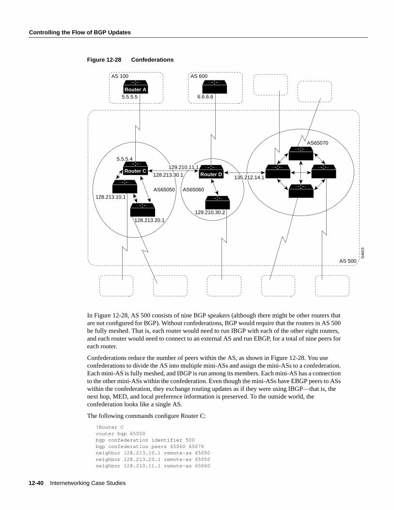
Figure 12-28 Confederations
In Figure 12-28, AS 500 consists of nine BGP speakers (although there might be other routers thatare not configured for BGP). Without confederations, BGP would require that the routers in AS 500be fully meshed. That is, each router would need to run IBGP with each of the other eight routers,and each router would need to connect to an external AS and run EBGP, for a total of nine peers foreach router.
Confederations reduce the number of peers within the AS, as shown in Figure 12-28. You useconfederations to divide the AS into multiple mini-ASs and assign the mini-ASs to a confederation.Each mini-AS is fully meshed, and IBGP is run among its members. Each mini-AS has a connectionto the other mini-ASs within the confederation. Even though the mini-ASs have EBGP peers to ASswithin the confederation, they exchange routing updates as if they were using IBGP—that is, thenext hop, MED, and local preference information is preserved. To the outside world, theconfederation looks like a single AS.
The following commands configure Router C:
!Router Crouter bgp 65050bgp confederation identifier 500bgp confederation peers 65060 65070neighbor 128.213.10.1 remote-as 65050neighbor 128.213.20.1 remote-as 65050neighbor 128.210.11.1 remote-as 65060
Router C
Router A
AS65070
AS 500
AS 100
5.5.5.5 6.6.6.6
AS 600
AS65050 AS65060
5.5.5.4
128.213.10.1
128.213.20.1
129.210.30.2
S46
03
Router D129.210.11.1
128.213.30.1 135.212.14.1
129.210.11.1
Using the Border Gateway Protocol for Interdomain Routing 12-41
Controlling the Flow of BGP Updates
neighbor 135.212.14.1 remote-as 65070neighbor 5.5.5.5 remote-as 100
Therouter bgp global configuration command specifies that Router C belongs to AS 50.
Thebgp confederation identifierrouter configuration command specifies that Router C belongs toconfederation 500.
The first twoneighbor remote-asrouter configuration commands establish IBGP connections to theother two routers within AS 65050. The second twoneighbor remote-ascommands establish BGPconnections with confederation peers 65060 and 65070. The lastneighbor remote-as commandestablishes an EBGP connection with external AS 100.
The following commands configure Router D:
!Router Drouter bgp 65060bgp confederation identifier 500bgp confederation peers 65050 65070neighbor 129.210.30.2 remote-as 65060neighbor 128.213.30.1 remote-as 65050neighbor 135.212.14.1 remote-as 65070neighbor 6.6.6.6 remote-as 600
Therouter bgp global configuration command specifies that Router D belongs to AS 65060.
Thebgp confederation identifierrouter configuration command specifies that Router D belongs toconfederation 500.
The firstneighbor remote-asrouter configuration command establishes an IBGP connection to theother router within AS 65060. The second twoneighbor remote-as commands establish BGPconnections with confederation peers 65050 and 65070. The lastneighbor remote-as commandestablishes an EBGP connection with AS 600.
The following commands configure Router A:
!Router Arouter bgp 100neighbor 5.5.5.4 remote-as 500
Theneighbor remote-as command establishes an EBGP connection with Router C. Router A isunaware of AS 65050, AS 65060, or AS 65070. Router A only has knowledge of AS 500.
Route ReflectorsRoute reflectors are another solution for the explosion of IBGP peering within an AS. As describedearlier in the section “Synchronization,” a BGP speaker does not advertise a route learned fromanother IBGP speaker to a third IBGP speaker. Route reflectors ease this limitation and allow arouter to advertise (reflect) IBGP-learned routes to other IBGP speakers, thereby reducing thenumber of IBGP peers within an AS.
The network shown in Figure 12-29 demonstrates how route reflectors work.
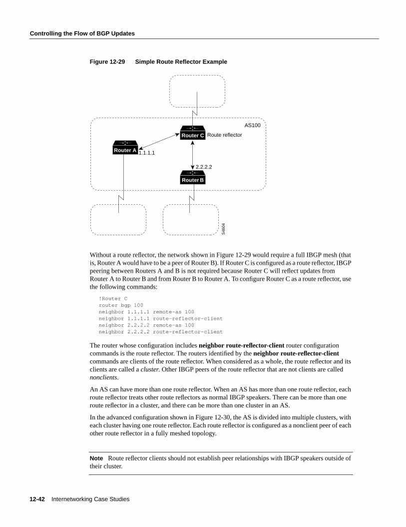
12-42 Internetworking Case Studies
Controlling the Flow of BGP Updates
Figure 12-29 Simple Route Reflector Example
Without a route reflector, the network shown in Figure 12-29 would require a full IBGP mesh (thatis, Router A would have to be a peer of Router B). If Router C is configured as a route reflector, IBGPpeering between Routers A and B is not required because Router C will reflect updates fromRouter A to Router B and from Router B to Router A. To configure Router C as a route reflector, usethe following commands:
!Router Crouter bgp 100neighbor 1.1.1.1 remote-as 100neighbor 1.1.1.1 route-reflector-clientneighbor 2.2.2.2 remote-as 100neighbor 2.2.2.2 route-reflector-client
The router whose configuration includesneighbor route-reflector-client router configurationcommands is the route reflector. The routers identified by theneighbor route-reflector-clientcommands are clients of the route reflector. When considered as a whole, the route reflector and itsclients are called acluster. Other IBGP peers of the route reflector that are not clients are callednonclients.
An AS can have more than one route reflector. When an AS has more than one route reflector, eachroute reflector treats other route reflectors as normal IBGP speakers. There can be more than oneroute reflector in a cluster, and there can be more than one cluster in an AS.
In the advanced configuration shown in Figure 12-30, the AS is divided into multiple clusters, witheach cluster having one route reflector. Each route reflector is configured as a nonclient peer of eachother route reflector in a fully meshed topology.
Note Route reflector clients should not establish peer relationships with IBGP speakers outside oftheir cluster.
Router A
Router C
Router B
Route reflector
1.1.1.1
2.2.2.2
AS100
S46
04
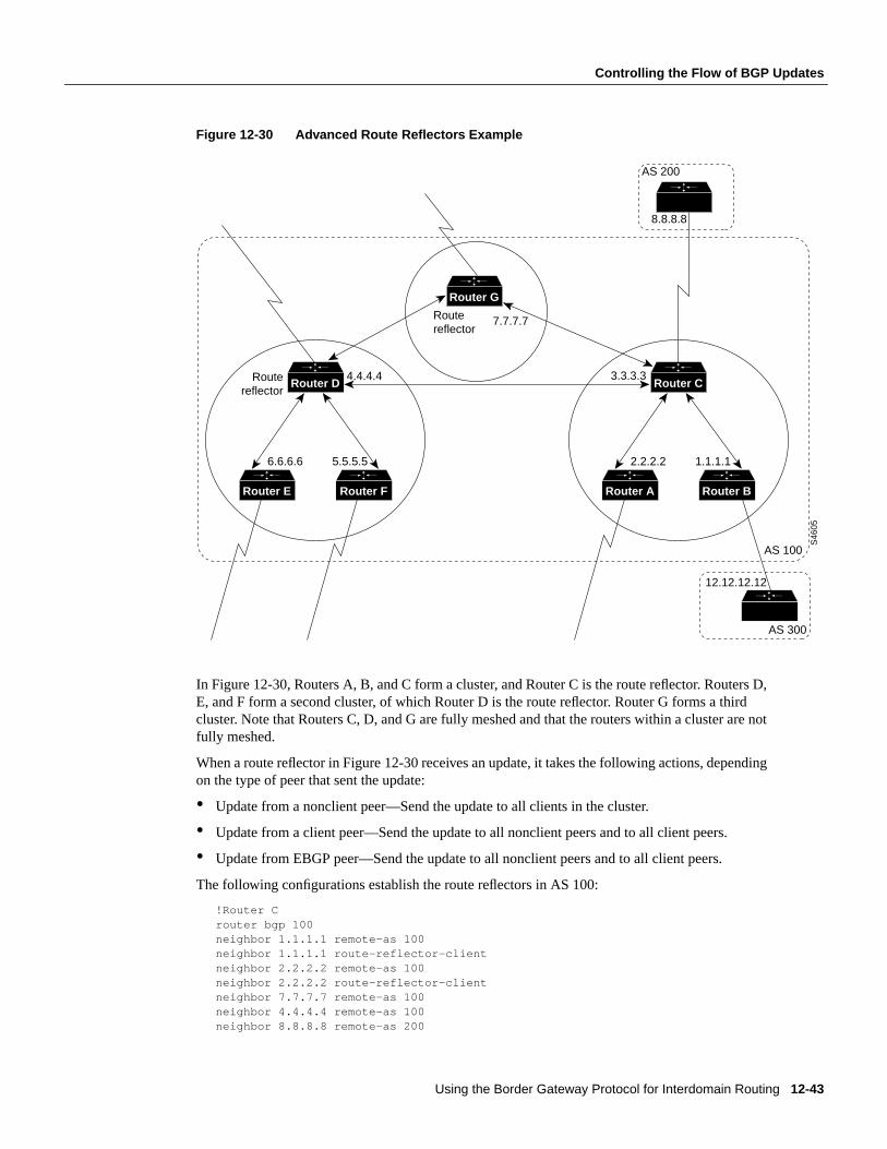
Using the Border Gateway Protocol for Interdomain Routing 12-43
Controlling the Flow of BGP Updates
Figure 12-30 Advanced Route Reflectors Example
In Figure 12-30, Routers A, B, and C form a cluster, and Router C is the route reflector. Routers D,E, and F form a second cluster, of which Router D is the route reflector. Router G forms a thirdcluster. Note that Routers C, D, and G are fully meshed and that the routers within a cluster are notfully meshed.
When a route reflector in Figure 12-30 receives an update, it takes the following actions, dependingon the type of peer that sent the update:
• Update from a nonclient peer—Send the update to all clients in the cluster.
• Update from a client peer—Send the update to all nonclient peers and to all client peers.
• Update from EBGP peer—Send the update to all nonclient peers and to all client peers.
The following configurations establish the route reflectors in AS 100:
!Router Crouter bgp 100neighbor 1.1.1.1 remote-as 100neighbor 1.1.1.1 route-reflector-clientneighbor 2.2.2.2 remote-as 100neighbor 2.2.2.2 route-reflector-clientneighbor 7.7.7.7 remote-as 100neighbor 4.4.4.4 remote-as 100neighbor 8.8.8.8 remote-as 200
Router D
Router FRouter E
Router G
AS 100
AS 200
6.6.6.6 5.5.5.5
4.4.4.4 3.3.3.3
7.7.7.7
8.8.8.8
AS 300
12.12.12.12
Routereflector
Routereflector
S46
05
Router C
Router BRouter A
2.2.2.2 1.1.1.1
12-44 Internetworking Case Studies
Controlling the Flow of BGP Updates
!Router Brouter bgp 100neighbor 3.3.3.3 remote-as 100neighbor 12.12.12.12 remote-as 300
!Router Drouter bgp 100neighbor 5.5.5.5 remote-as 100neighbor 5.5.5.5 route-reflector-clientneighbor 6.6.6.6 remote-as 100neighbor 6.6.6.6 route-reflector-clientneighbor 3.3.3.3 remote-as 100neighbor 7.7.7.7 remote-as 100
If a set clause is used to modify an attribute, a routing loop may occur when the IBGP-learned routesare reflected. BGP automatically prevents the set clause of outgoing route maps from affectingroutes reflected to IBGP peers. Another automatic restriction concerns theneighbor next-hop-selfrouter configuration command. Because the next hop of reflected routes should not be changed, theneighbor next-hop-selfcommand only affects the next hop of EBGP-learned routes when used withroute reflectors.
Two techniques prevent routing loops in route reflector configurations:
• Using an Originator ID
• Using a Cluster List
Using an Originator IDThe originator ID is a 4-byte BGP attribute that is created by the route reflector. This attribute carriesthe router ID of the originator of the route in the local AS. If, because of poor configuration, theupdate comes back to the originator, the originator ignores it.
Using a Cluster ListUsually a cluster has a single route reflector, in which case, the cluster is identified by the router IDof the route reflector. To increase redundancy and avoid single points of failure, a cluster might havemore than one route reflector. When a cluster has more than one route reflector, all of the routereflectors in the cluster need to be configured with a 4-byte cluster ID. The cluster ID allows routereflectors to recognize updates from other route reflectors in the same cluster.
A cluster list is a sequence of cluster IDs that an update has traversed. When a route reflector sendsa route from its clients to nonclients outside of the cluster, it appends the local cluster ID to thecluster list. If the route reflector receives an update whose cluster list contains the local cluster ID,the update is ignored.
In Figure 12-31, Routers D, E, F, and H belong to the same cluster; Routers D and H are routereflectors for the same cluster. Note that Routers D and H maintain a fully meshed peeringrelationship with the other route reflectors in AS 100 (that is, with Routers C and G). If Router Dgoes down, Router H is prepared to take its place.
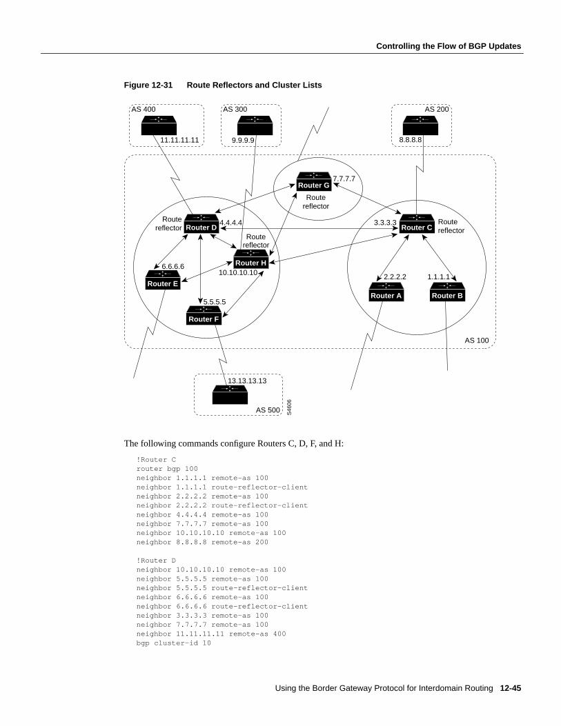
Using the Border Gateway Protocol for Interdomain Routing 12-45
Controlling the Flow of BGP Updates
Figure 12-31 Route Reflectors and Cluster Lists
The following commands configure Routers C, D, F, and H:
!Router Crouter bgp 100neighbor 1.1.1.1 remote-as 100neighbor 1.1.1.1 route-reflector-clientneighbor 2.2.2.2 remote-as 100neighbor 2.2.2.2 route-reflector-clientneighbor 4.4.4.4 remote-as 100neighbor 7.7.7.7 remote-as 100neighbor 10.10.10.10 remote-as 100neighbor 8.8.8.8 remote-as 200
!Router Dneighbor 10.10.10.10 remote-as 100neighbor 5.5.5.5 remote-as 100neighbor 5.5.5.5 route-reflector-clientneighbor 6.6.6.6 remote-as 100neighbor 6.6.6.6 route-reflector-clientneighbor 3.3.3.3 remote-as 100neighbor 7.7.7.7 remote-as 100neighbor 11.11.11.11 remote-as 400bgp cluster-id 10
Router D
Router H
Router E
Router F
Router G
AS 100
AS 200
6.6.6.6
5.5.5.5
4.4.4.4 3.3.3.3
7.7.7.7
8.8.8.8
AS 400
11.11.11.11
AS 500
13.13.13.13
Routereflector
Routereflector
10.10.10.10
Routereflector
Routereflector
S46
06
AS 300
9.9.9.9
Router C
Router BRouter A
2.2.2.2 1.1.1.1
12-46 Internetworking Case Studies
Controlling the Flow of BGP Updates
!Router Frouter bgp 100neighbor 10.10.10.10 remote-as 100neighbor 4.4.4.4 remote-as 100neighbor 13.13.13.13 remote-as 500
!Router Hrouter bgp 100neighbor 4.4.4.4 remote-as 100neighbor 5.5.5.5 remote-as 100neighbor 5.5.5.5 route-reflector-clientneighbor 6.6.6.6 remote-as 100neighbor 6.6.6.6 route-reflector-clientneighbor 7.7.7.7 remote-as 100neighbor 3.3.3.3 remote-as 100neighbor 9.9.9.9 remote-as 300bgp cluster-id 10
The configurations for Routers D and H include thebgp cluster-id router configuration command,which sets the cluster ID to 10. The configuration for Router C does not include thebgp cluster-idcommand because Router C is the only route reflector in its cluster.
Note You should not configure a peer group within a route reflector cluster. Clients inside a clusterdo not have direct IBGP peers; instead, they exchange updates through the route reflector.Configuring peer groups within such a cluster might cause a withdrawal to the source of a route onthe route reflector to be sent to all clients in the cluster. If you use theno bgp client-to-clientreflection command to turn off client-to-client reflection on the route reflector and if you enableredundant BGP peering between the clients, you can use peer groups within a cluster.
Route Reflectors and Conventional BGP SpeakersIt is normal for an AS in which route reflectors are configured to have BGP speakers that do notsupport route reflection. Such routers are known as conventional BGP speakers.
In Figure 12-32, Routers D, E, and F form a route reflector cluster, and Routers A, B, and C areconventional BGP speakers.
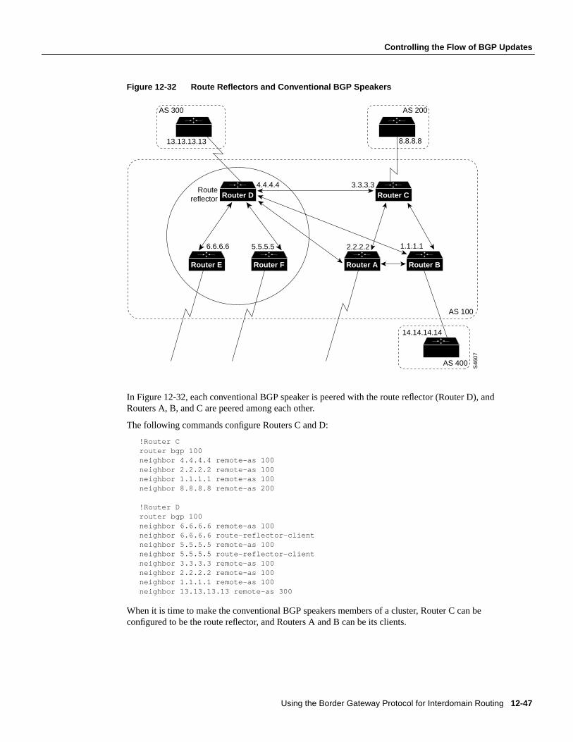
Using the Border Gateway Protocol for Interdomain Routing 12-47
Controlling the Flow of BGP Updates
Figure 12-32 Route Reflectors and Conventional BGP Speakers
In Figure 12-32, each conventional BGP speaker is peered with the route reflector (Router D), andRouters A, B, and C are peered among each other.
The following commands configure Routers C and D:
!Router Crouter bgp 100neighbor 4.4.4.4 remote-as 100neighbor 2.2.2.2 remote-as 100neighbor 1.1.1.1 remote-as 100neighbor 8.8.8.8 remote-as 200
!Router Drouter bgp 100neighbor 6.6.6.6 remote-as 100neighbor 6.6.6.6 route-reflector-clientneighbor 5.5.5.5 remote-as 100neighbor 5.5.5.5 route-reflector-clientneighbor 3.3.3.3 remote-as 100neighbor 2.2.2.2 remote-as 100neighbor 1.1.1.1 remote-as 100neighbor 13.13.13.13 remote-as 300
When it is time to make the conventional BGP speakers members of a cluster, Router C can beconfigured to be the route reflector, and Routers A and B can be its clients.
Router D
Router FRouter E
AS 100
AS 200
6.6.6.6 5.5.5.5
4.4.4.4 3.3.3.3
8.8.8.8
AS 400
14.14.14.14
Routereflector
S46
07
Router C
Router BRouter A
2.2.2.2 1.1.1.1
AS 300
13.13.13.13
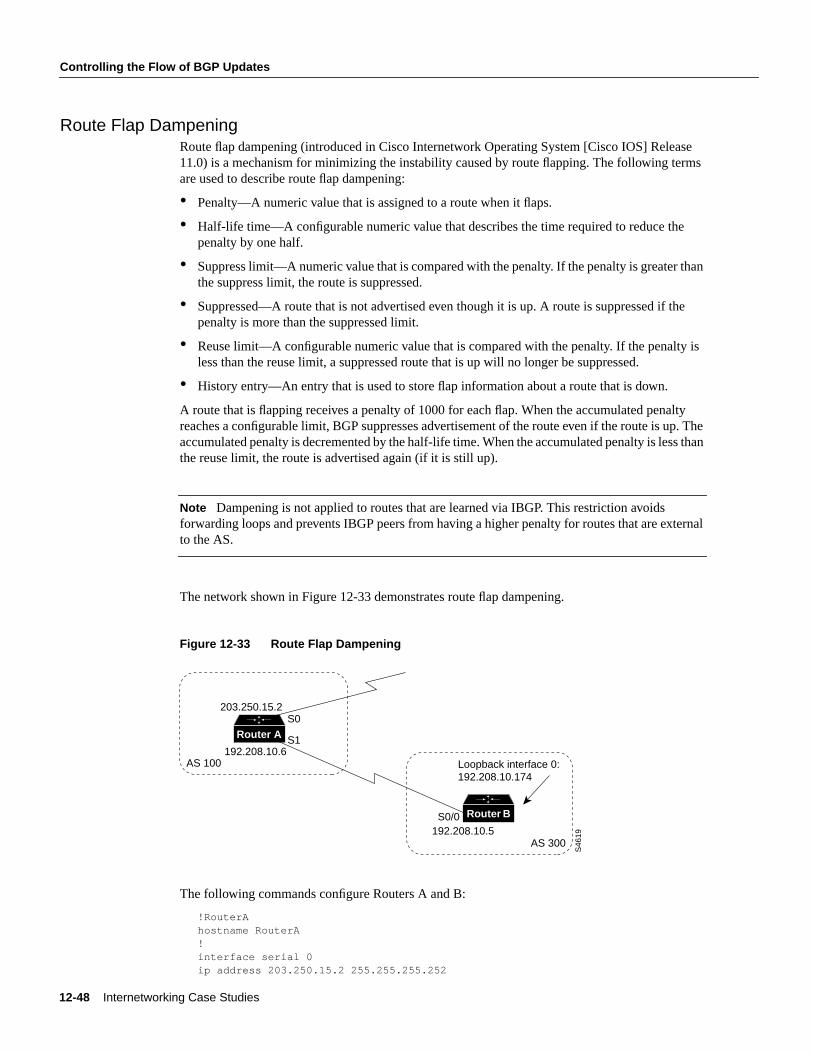
12-48 Internetworking Case Studies
Controlling the Flow of BGP Updates
Route Flap DampeningRoute flap dampening (introduced in Cisco Internetwork Operating System [Cisco IOS] Release11.0) is a mechanism for minimizing the instability caused by route flapping. The following termsare used to describe route flap dampening:
• Penalty—A numeric value that is assigned to a route when it flaps.
• Half-life time—A configurable numeric value that describes the time required to reduce thepenalty by one half.
• Suppress limit—A numeric value that is compared with the penalty. If the penalty is greater thanthe suppress limit, the route is suppressed.
• Suppressed—A route that is not advertised even though it is up. A route is suppressed if thepenalty is more than the suppressed limit.
• Reuse limit—A configurable numeric value that is compared with the penalty. If the penalty isless than the reuse limit, a suppressed route that is up will no longer be suppressed.
• History entry—An entry that is used to store flap information about a route that is down.
A route that is flapping receives a penalty of 1000 for each flap. When the accumulated penaltyreaches a configurable limit, BGP suppresses advertisement of the route even if the route is up. Theaccumulated penalty is decremented by the half-life time. When the accumulated penalty is less thanthe reuse limit, the route is advertised again (if it is still up).
Note Dampening is not applied to routes that are learned via IBGP. This restriction avoidsforwarding loops and prevents IBGP peers from having a higher penalty for routes that are externalto the AS.
The network shown in Figure 12-33 demonstrates route flap dampening.
Figure 12-33 Route Flap Dampening
The following commands configure Routers A and B:
!RouterAhostname RouterA!interface serial 0ip address 203.250.15.2 255.255.255.252
Router A
Router B
192.208.10.6
203.250.15.2
192.208.10.5
Loopback interface 0:192.208.10.174
AS 100
S1
S0
S0/0
AS 300
S46
19
Using the Border Gateway Protocol for Interdomain Routing 12-49
Controlling the Flow of BGP Updates
interface serial 1ip address 192.208.10.6 255.255.255.252!router bgp 100bgp dampeningnetwork 203.250.15.0neighbor 192.208.10.5 remote-as 300
!RouterBhostname RouterB!interface loopback 0ip address 192.208.10.174 255.255.255.192!interface serial 0/0ip address 192.208.10.5 255.255.255.252!router bgp 300network 192.208.10.0neighbor 192.208.10.6 remote-as 100
Router A is configured for route dampening. Assuming that the EBGP link to Router B is stable, theBGP table on Router A looks like this:
RouterB# show ip bgptable version is 24, local router ID is 203.250.15.2Status codes: s suppressed, d damped, h history, * valid, > best, i - internalOrigin codes: i - IGP, e - EGP, ? - incomplete
Network Next Hop Metric LocPrf Weight Path*> 192.208.10.0 192.208.10.5 0 0 300 i*> 203.250.15.0 0.0.0.0 0 32768 i
To simulate a route flap, enter this command on Router B:
clear ip bgp 192.208.10.6
Now, the BGP table on Router A looks like this:
RouterA# show ip bgptable version is 24, local router ID is 203.250.15.2Status codes: s suppressed, d damped, h history, * valid, > best, i - internalOrigin codes: i - IGP, e - EGP, ? - incomplete
Network Next Hop Metric LocPrf Weight Path h 192.208.10.0 192.208.10.5 0 0 300 i*> 203.250.15.0 0.0.0.0 0 32768 i
Because the route for 192.208.10.0. has flapped, the BGP entry for 192.208.10.0 has been withdrawnand put into the history state.
The output of theshow ip bgp EXEC command for network 192.208.10.0 is as follows:
RouterA# show ip bgp 192.208.10.0BGP routing table entry for 192.208.10.5 255.255.255.0, version 25Paths: (1 available, no best path)300 (history entry) 192.208.10.5 from 192.208.10.5 (192.208.10.174)Origin IGP, metric 0, externalDampinfo: penalty 1000, flapped 1 times in 0:02:03
12-50 Internetworking Case Studies
Practical Design Example
The route has been given a penalty (1000) for flapping but the penalty is still below the suppress limit(default 2000). Because the route is down, it is marked as a history entry. If the route flaps a few moretimes, theshow ip bgp command displays the following:
RouterA# show ip bgptable version is 32, local router ID is 203.250.15.2Status codes: s suppressed, d damped, h history, * valid, > best, i - internalOrigin codes: i - IGP, e - EGP, ? - incomplete
Network Next Hop Metric LocPrf Weight Path*d 192.208.10.0 192.208.10.5 0 0 300 i*> 203.250.15.0 0.0.0.0 0 32768 i
The output of theshow ip bgp command for network 192.208.10.0 is as follows:
RouterA# show ip bgp 192.208.10.0BGP routing table entry for 192.208.10.5 255.255.255.0, version 32Paths: (1 available, no best path)300, (suppressed due to dampening) 192.208.10.5 from 192.208.10.5 (192.208.10.174)Origin IGP, metric 0, externalDampinfo: penalty 2615, flapped 3 times in 0:05:18, reuse in 0:27:00
The route is up, but because the penalty is greater than the suppress limit, it is suppressed. The routewill be reused when the penalty reaches the reuse limit (default 750). The dampening informationwill be purged when the penalty becomes less than half of the reuse limit (750/2 = 350).
Practical Design ExampleFigure 12-34 shows a BGP network that demonstrates the types of topologies that are typical amongISPs.
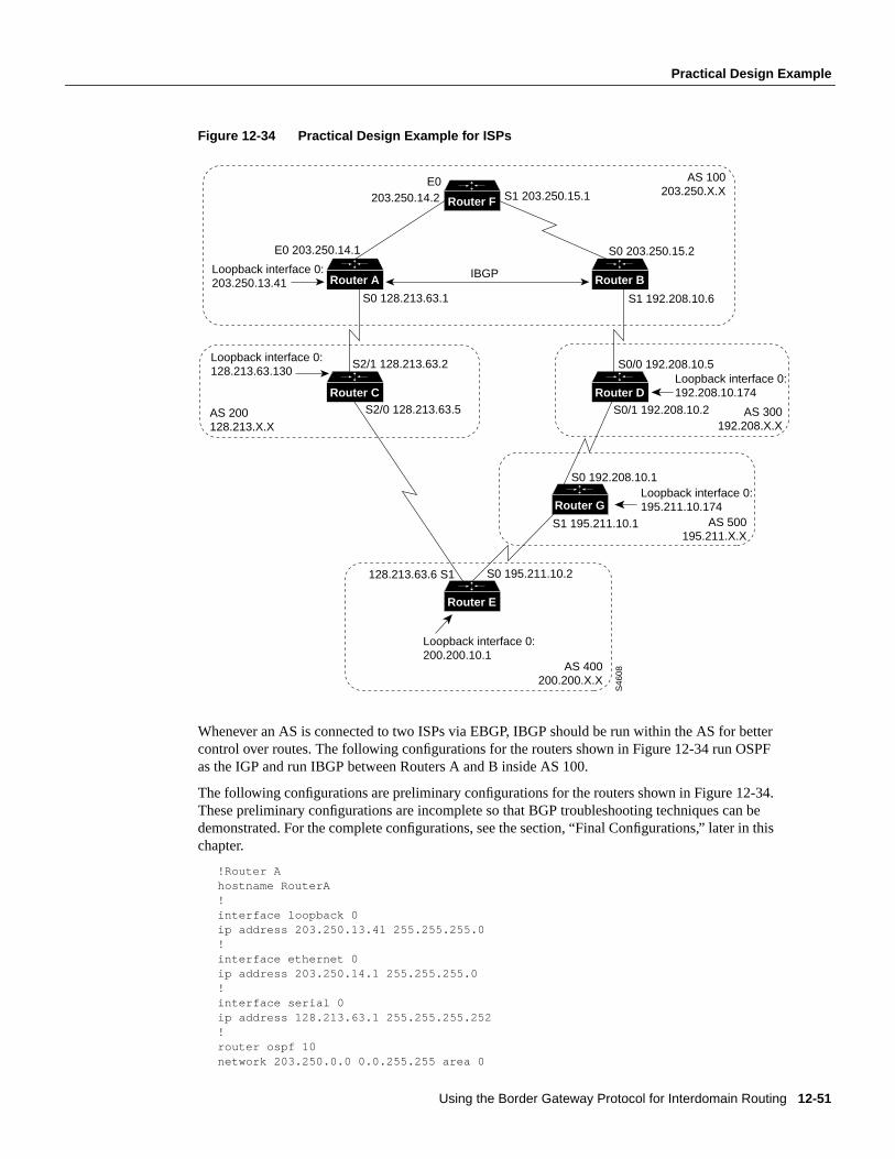
Using the Border Gateway Protocol for Interdomain Routing 12-51
Practical Design Example
Figure 12-34 Practical Design Example for ISPs
Whenever an AS is connected to two ISPs via EBGP, IBGP should be run within the AS for bettercontrol over routes. The following configurations for the routers shown in Figure 12-34 run OSPFas the IGP and run IBGP between Routers A and B inside AS 100.
The following configurations are preliminary configurations for the routers shown in Figure 12-34.These preliminary configurations are incomplete so that BGP troubleshooting techniques can bedemonstrated. For the complete configurations, see the section, “Final Configurations,” later in thischapter.
!Router Ahostname RouterA!interface loopback 0ip address 203.250.13.41 255.255.255.0!interface ethernet 0ip address 203.250.14.1 255.255.255.0!interface serial 0ip address 128.213.63.1 255.255.255.252!router ospf 10network 203.250.0.0 0.0.255.255 area 0
Router F
Router A Router B
Router C Router D
Router G
Router E
E0 AS 100203.250.X.X
AS 300192.208.X.X
AS 500195.211.X.X
AS 400200.200.X.X
203.250.14.2 S1 203.250.15.1
Loopback interface 0: 203.250.13.41
Loopback interface 0: 128.213.63.130
S0 128.213.63.1
128.213.63.6 S1 S0 195.211.10.2
S2/1 128.213.63.2 S0/0 192.208.10.5
S0 192.208.10.1
S0/1 192.208.10.2
S1 195.211.10.1
Loopback interface 0: 192.208.10.174
Loopback interface 0: 195.211.10.174
Loopback interface 0: 200.200.10.1
S2/0 128.213.63.5AS 200128.213.X.X
S0 203.250.15.2
S1 192.208.10.6
E0 203.250.14.1
S46
08
IBGP
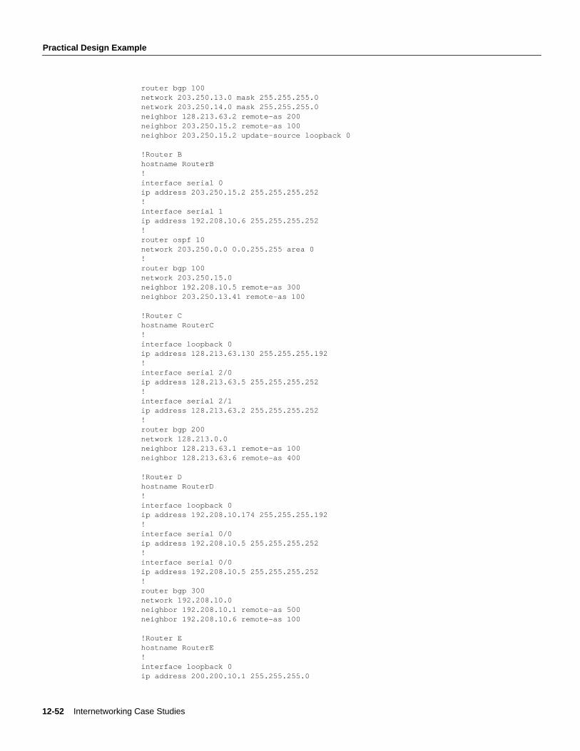
12-52 Internetworking Case Studies
Practical Design Example
router bgp 100network 203.250.13.0 mask 255.255.255.0network 203.250.14.0 mask 255.255.255.0neighbor 128.213.63.2 remote-as 200neighbor 203.250.15.2 remote-as 100neighbor 203.250.15.2 update-source loopback 0
!Router Bhostname RouterB!interface serial 0ip address 203.250.15.2 255.255.255.252!interface serial 1ip address 192.208.10.6 255.255.255.252!router ospf 10network 203.250.0.0 0.0.255.255 area 0!router bgp 100network 203.250.15.0neighbor 192.208.10.5 remote-as 300neighbor 203.250.13.41 remote-as 100
!Router Chostname RouterC!interface loopback 0ip address 128.213.63.130 255.255.255.192!interface serial 2/0ip address 128.213.63.5 255.255.255.252!interface serial 2/1ip address 128.213.63.2 255.255.255.252!router bgp 200network 128.213.0.0neighbor 128.213.63.1 remote-as 100neighbor 128.213.63.6 remote-as 400
!Router Dhostname RouterD!interface loopback 0ip address 192.208.10.174 255.255.255.192!interface serial 0/0ip address 192.208.10.5 255.255.255.252!interface serial 0/0ip address 192.208.10.5 255.255.255.252!router bgp 300network 192.208.10.0neighbor 192.208.10.1 remote-as 500neighbor 192.208.10.6 remote-as 100
!Router Ehostname RouterE!interface loopback 0ip address 200.200.10.1 255.255.255.0
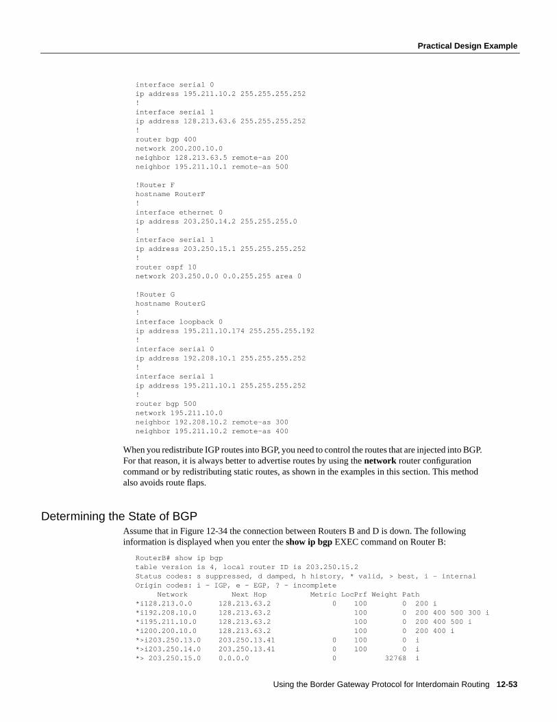
Using the Border Gateway Protocol for Interdomain Routing 12-53
Practical Design Example
interface serial 0ip address 195.211.10.2 255.255.255.252!interface serial 1ip address 128.213.63.6 255.255.255.252!router bgp 400network 200.200.10.0neighbor 128.213.63.5 remote-as 200neighbor 195.211.10.1 remote-as 500
!Router Fhostname RouterF!interface ethernet 0ip address 203.250.14.2 255.255.255.0!interface serial 1ip address 203.250.15.1 255.255.255.252!router ospf 10network 203.250.0.0 0.0.255.255 area 0
!Router Ghostname RouterG!interface loopback 0ip address 195.211.10.174 255.255.255.192!interface serial 0ip address 192.208.10.1 255.255.255.252!interface serial 1ip address 195.211.10.1 255.255.255.252!router bgp 500network 195.211.10.0neighbor 192.208.10.2 remote-as 300neighbor 195.211.10.2 remote-as 400
When you redistribute IGP routes into BGP, you need to control the routes that are injected into BGP.For that reason, it is always better to advertise routes by using thenetwork router configurationcommand or by redistributing static routes, as shown in the examples in this section. This methodalso avoids route flaps.
Determining the State of BGPAssume that in Figure 12-34 the connection between Routers B and D is down. The followinginformation is displayed when you enter theshow ip bgp EXEC command on Router B:
RouterB# show ip bgptable version is 4, local router ID is 203.250.15.2Status codes: s suppressed, d damped, h history, * valid, > best, i - internalOrigin codes: i - IGP, e - EGP, ? - incomplete Network Next Hop Metric LocPrf Weight Path*i128.213.0.0 128.213.63.2 0 100 0 200 i*i192.208.10.0 128.213.63.2 100 0 200 400 500 300 i*i195.211.10.0 128.213.63.2 100 0 200 400 500 i*i200.200.10.0 128.213.63.2 100 0 200 400 i*>i203.250.13.0 203.250.13.41 0 100 0 i*>i203.250.14.0 203.250.13.41 0 100 0 i*> 203.250.15.0 0.0.0.0 0 32768 i
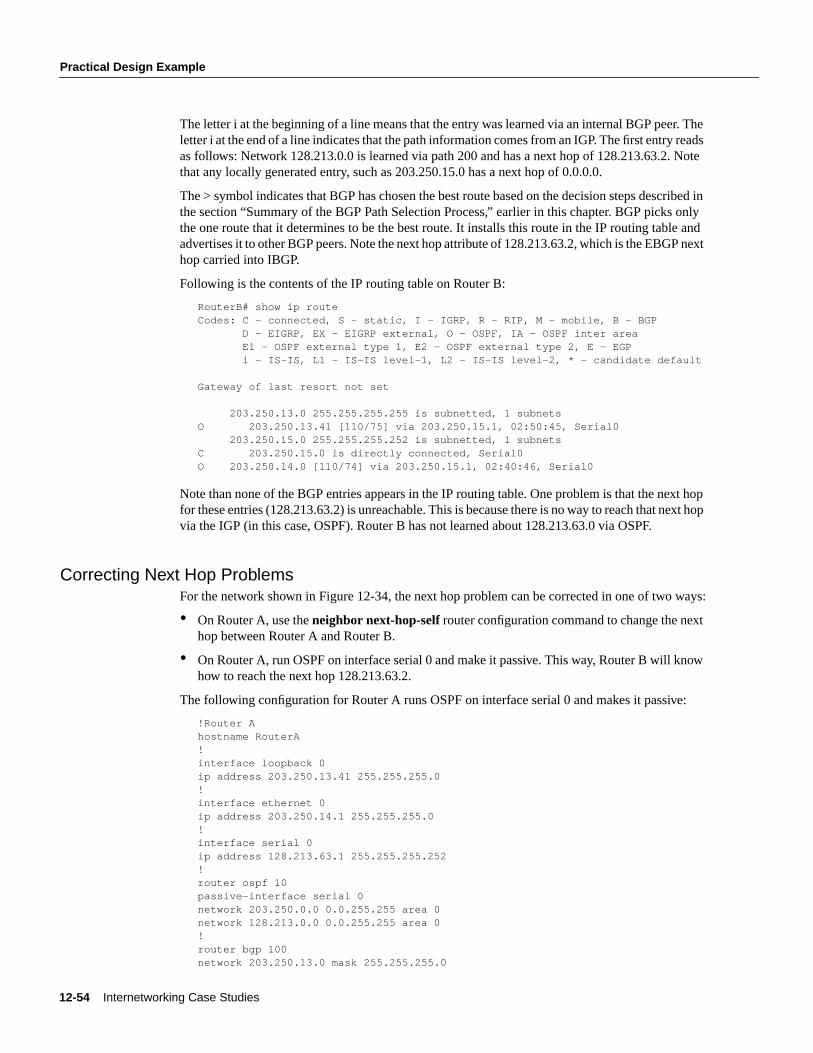
12-54 Internetworking Case Studies
Practical Design Example
The letter i at the beginning of a line means that the entry was learned via an internal BGP peer. Theletter i at the end of a line indicates that the path information comes from an IGP. The first entry readsas follows: Network 128.213.0.0 is learned via path 200 and has a next hop of 128.213.63.2. Notethat any locally generated entry, such as 203.250.15.0 has a next hop of 0.0.0.0.
The > symbol indicates that BGP has chosen the best route based on the decision steps described inthe section “Summary of the BGP Path Selection Process,” earlier in this chapter. BGP picks onlythe one route that it determines to be the best route. It installs this route in the IP routing table andadvertises it to other BGP peers. Note the next hop attribute of 128.213.63.2, which is the EBGP nexthop carried into IBGP.
Following is the contents of the IP routing table on Router B:
RouterB# show ip routeCodes: C - connected, S - static, I - IGRP, R - RIP, M - mobile, B - BGP D - EIGRP, EX - EIGRP external, O - OSPF, IA - OSPF inter area E1 - OSPF external type 1, E2 - OSPF external type 2, E - EGP i - IS-IS, L1 - IS-IS level-1, L2 - IS-IS level-2, * - candidate default
Gateway of last resort not set
203.250.13.0 255.255.255.255 is subnetted, 1 subnetsO 203.250.13.41 [110/75] via 203.250.15.1, 02:50:45, Serial0 203.250.15.0 255.255.255.252 is subnetted, 1 subnetsC 203.250.15.0 is directly connected, Serial0O 203.250.14.0 [110/74] via 203.250.15.1, 02:40:46, Serial0
Note than none of the BGP entries appears in the IP routing table. One problem is that the next hopfor these entries (128.213.63.2) is unreachable. This is because there is no way to reach that next hopvia the IGP (in this case, OSPF). Router B has not learned about 128.213.63.0 via OSPF.
Correcting Next Hop ProblemsFor the network shown in Figure 12-34, the next hop problem can be corrected in one of two ways:
• On Router A, use theneighbor next-hop-selfrouter configuration command to change the nexthop between Router A and Router B.
• On Router A, run OSPF on interface serial 0 and make it passive. This way, Router B will knowhow to reach the next hop 128.213.63.2.
The following configuration for Router A runs OSPF on interface serial 0 and makes it passive:
!Router Ahostname RouterA!interface loopback 0ip address 203.250.13.41 255.255.255.0!interface ethernet 0ip address 203.250.14.1 255.255.255.0!interface serial 0ip address 128.213.63.1 255.255.255.252!router ospf 10passive-interface serial 0network 203.250.0.0 0.0.255.255 area 0network 128.213.0.0 0.0.255.255 area 0!router bgp 100network 203.250.13.0 mask 255.255.255.0
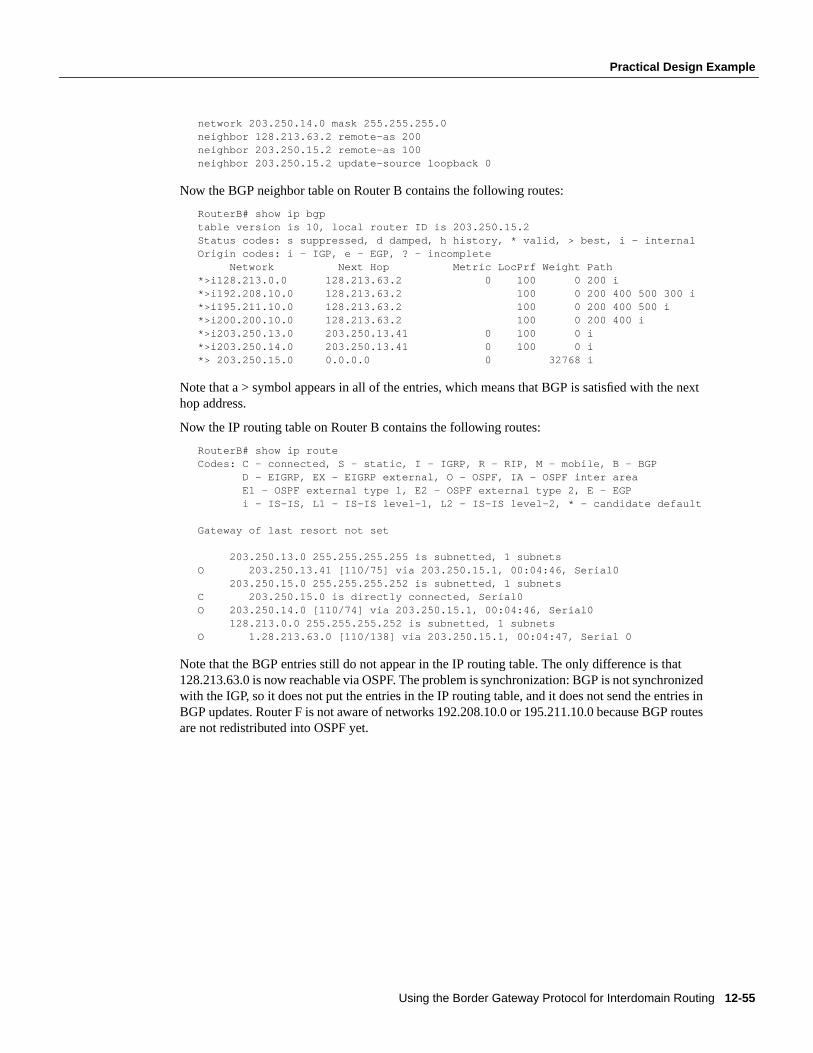
Using the Border Gateway Protocol for Interdomain Routing 12-55
Practical Design Example
network 203.250.14.0 mask 255.255.255.0neighbor 128.213.63.2 remote-as 200neighbor 203.250.15.2 remote-as 100neighbor 203.250.15.2 update-source loopback 0
Now the BGP neighbor table on Router B contains the following routes:
RouterB# show ip bgptable version is 10, local router ID is 203.250.15.2Status codes: s suppressed, d damped, h history, * valid, > best, i - internalOrigin codes: i - IGP, e - EGP, ? - incomplete Network Next Hop Metric LocPrf Weight Path*>i128.213.0.0 128.213.63.2 0 100 0 200 i*>i192.208.10.0 128.213.63.2 100 0 200 400 500 300 i*>i195.211.10.0 128.213.63.2 100 0 200 400 500 i*>i200.200.10.0 128.213.63.2 100 0 200 400 i*>i203.250.13.0 203.250.13.41 0 100 0 i*>i203.250.14.0 203.250.13.41 0 100 0 i*> 203.250.15.0 0.0.0.0 0 32768 i
Note that a > symbol appears in all of the entries, which means that BGP is satisfied with the nexthop address.
Now the IP routing table on Router B contains the following routes:
RouterB# show ip routeCodes: C - connected, S - static, I - IGRP, R - RIP, M - mobile, B - BGP D - EIGRP, EX - EIGRP external, O - OSPF, IA - OSPF inter area E1 - OSPF external type 1, E2 - OSPF external type 2, E - EGP i - IS-IS, L1 - IS-IS level-1, L2 - IS-IS level-2, * - candidate default
Gateway of last resort not set
203.250.13.0 255.255.255.255 is subnetted, 1 subnetsO 203.250.13.41 [110/75] via 203.250.15.1, 00:04:46, Serial0 203.250.15.0 255.255.255.252 is subnetted, 1 subnetsC 203.250.15.0 is directly connected, Serial0O 203.250.14.0 [110/74] via 203.250.15.1, 00:04:46, Serial0 128.213.0.0 255.255.255.252 is subnetted, 1 subnetsO 1.28.213.63.0 [110/138] via 203.250.15.1, 00:04:47, Serial 0
Note that the BGP entries still do not appear in the IP routing table. The only difference is that128.213.63.0 is now reachable via OSPF. The problem is synchronization: BGP is not synchronizedwith the IGP, so it does not put the entries in the IP routing table, and it does not send the entries inBGP updates. Router F is not aware of networks 192.208.10.0 or 195.211.10.0 because BGP routesare not redistributed into OSPF yet.
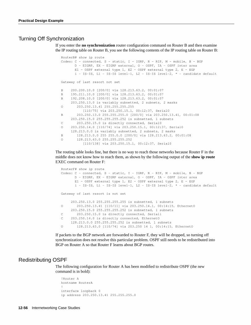
12-56 Internetworking Case Studies
Practical Design Example
Turning Off SynchronizationIf you enter theno synchronizationrouter configuration command on Router B and then examinethe IP routing table on Router B, you see the following contents of the IP routing table on Router B:
RouterB# show ip routeCodes: C - connected, S - static, I - IGRP, R - RIP, M - mobile, B - BGP D - EIGRP, EX - EIGRP external, O - OSPF, IA - OSPF inter area E1 - OSPF external type 1, E2 - OSPF external type 2, E - EGP i - IS-IS, L1 - IS-IS level-1, L2 - IS-IS level-2, * - candidate default
Gateway of last resort not set
B 200.200.10.0 [200/0] via 128.213.63.2, 00:01:07B 195.211.10.0 [200/0] via 128.213.63.2, 00:01:07B 192.208.10.0 [200/0] via 128.213.63.2, 00:01:07 203.250.13.0 is variably subnetted, 2 subnets, 2 masksO 203.250.13.41 255.255.255.255 [110/75] via 203.250.15.1, 00:12:37, Serial0B 203.250.13.0 255.255.255.0 [200/0] via 203.250.13.41, 00:01:08 203.250.15.0 255.255.255.252 is subnetted, 1 subnetsC 203.250.15.0 is directly connected, Serial0O 203.250.14.0 [110/74] via 203.250.15.1, 00:12:37, Serial0 128.213.0.0 is variably subnetted, 2 subnets, 2 masksB 128.213.0.0 255 255.0.0 [200/0] via 128.213.63.2, 00:01:08O 128.213.63.0 255.255.255.252 [110/138] via 203.250.15.1, 00:12:37, Serial0
The routing table looks fine, but there is no way to reach those networks because Router F in themiddle does not know how to reach them, as shown by the following output of theshow ip routeEXEC command on Router F:
RouterF# show ip routeCodes: C - connected, S - static, I - IGRP, R - RIP, M - mobile, B - BGP D - EIGRP, EX - EIGRP external, O - OSPF, IA - OSPF inter area E1 - OSPF external type 1, E2 - OSPF external type 2, E - EGP i - IS-IS, L1 - IS-IS level-1, L2 - IS-IS level-2, * - candidate default
Gateway of last resort is not set
203.250.13.0 255.255.255.255 is subnetted, 1 subnetsO 203.250.13.41 [110/11] via 203.250.14.1, 00:14:15, EthernetO 203.250.15.0 255.255.255.252 is subnetted, 1 subnetsC 203.250.15.0 is directly connected, SeriallC 203.250.14.0 is directly connected, EthernetO 128.213.0.0 255.255.255.252 is subnetted, 1 subnetsO 128.213.63.0 [110/74] via 203.250 14 1, 00:14:15, EthernetO
If packets to the BGP network are forwarded to Router F, they will be dropped, so turning offsynchronization does not resolve this particular problem. OSPF still needs to be redistributed intoBGP on Router A so that Router F learns about BGP routes.
Redistributing OSPFThe following configuration for Router A has been modified to redistribute OSPF (the newcommand is in bold):
!Router Ahostname RouterA!interface loopback 0ip address 203.250.13.41 255.255.255.0
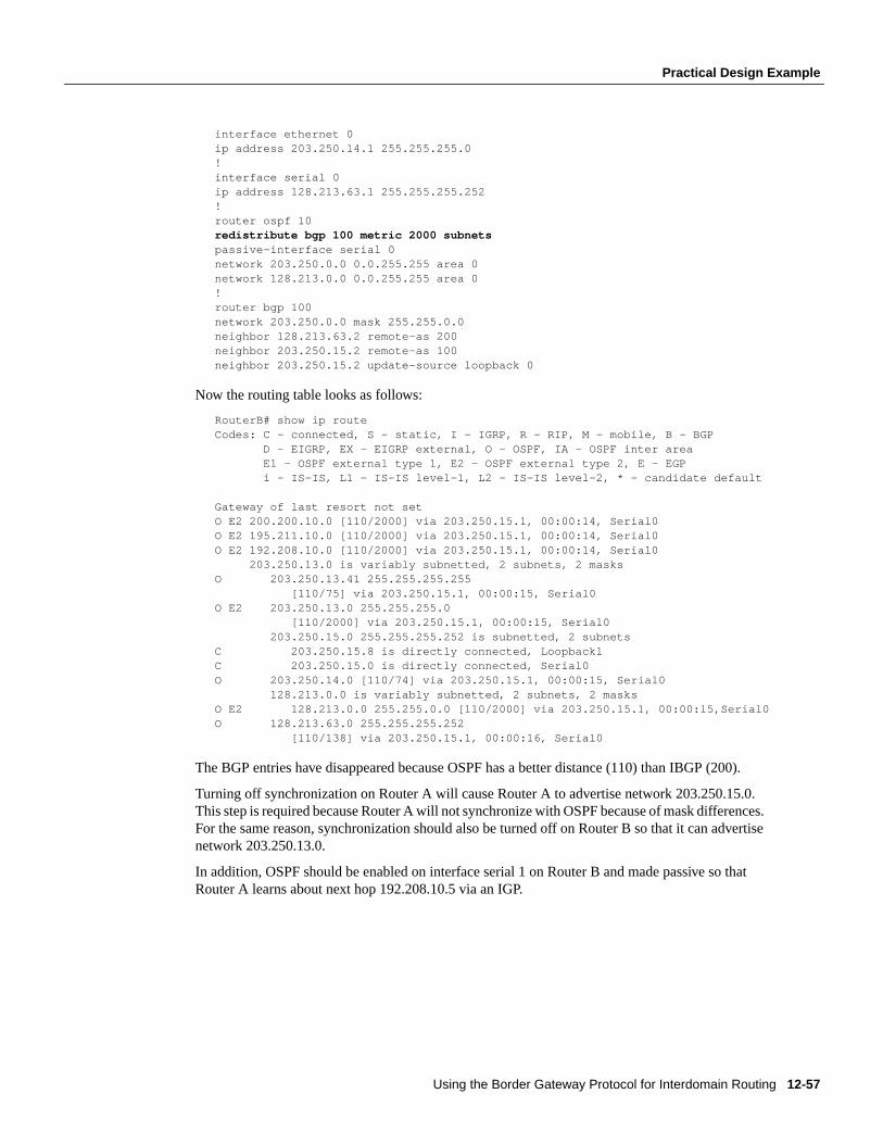
Using the Border Gateway Protocol for Interdomain Routing 12-57
Practical Design Example
interface ethernet 0ip address 203.250.14.1 255.255.255.0!interface serial 0ip address 128.213.63.1 255.255.255.252!router ospf 10redistribute bgp 100 metric 2000 subnetspassive-interface serial 0network 203.250.0.0 0.0.255.255 area 0network 128.213.0.0 0.0.255.255 area 0!router bgp 100network 203.250.0.0 mask 255.255.0.0neighbor 128.213.63.2 remote-as 200neighbor 203.250.15.2 remote-as 100neighbor 203.250.15.2 update-source loopback 0
Now the routing table looks as follows:
RouterB# show ip routeCodes: C - connected, S - static, I - IGRP, R - RIP, M - mobile, B - BGP D - EIGRP, EX - EIGRP external, O - OSPF, IA - OSPF inter area E1 - OSPF external type 1, E2 - OSPF external type 2, E - EGP i - IS-IS, L1 - IS-IS level-1, L2 - IS-IS level-2, * - candidate default
Gateway of last resort not setO E2 200.200.10.0 [110/2000] via 203.250.15.1, 00:00:14, Serial0O E2 195.211.10.0 [110/2000] via 203.250.15.1, 00:00:14, Serial0O E2 192.208.10.0 [110/2000] via 203.250.15.1, 00:00:14, Serial0 203.250.13.0 is variably subnetted, 2 subnets, 2 masksO 203.250.13.41 255.255.255.255 [110/75] via 203.250.15.1, 00:00:15, Serial0O E2 203.250.13.0 255.255.255.0 [110/2000] via 203.250.15.1, 00:00:15, Serial0 203.250.15.0 255.255.255.252 is subnetted, 2 subnetsC 203.250.15.8 is directly connected, LoopbacklC 203.250.15.0 is directly connected, Serial0O 203.250.14.0 [110/74] via 203.250.15.1, 00:00:15, Serial0 128.213.0.0 is variably subnetted, 2 subnets, 2 masksO E2 128.213.0.0 255.255.0.0 [110/2000] via 203.250.15.1, 00:00:l5,Serial0O 128.213.63.0 255.255.255.252 [110/138] via 203.250.15.1, 00:00:16, Serial0
The BGP entries have disappeared because OSPF has a better distance (110) than IBGP (200).
Turning off synchronization on Router A will cause Router A to advertise network 203.250.15.0.This step is required because Router A will not synchronize with OSPF because of mask differences.For the same reason, synchronization should also be turned off on Router B so that it can advertisenetwork 203.250.13.0.
In addition, OSPF should be enabled on interface serial 1 on Router B and made passive so thatRouter A learns about next hop 192.208.10.5 via an IGP.
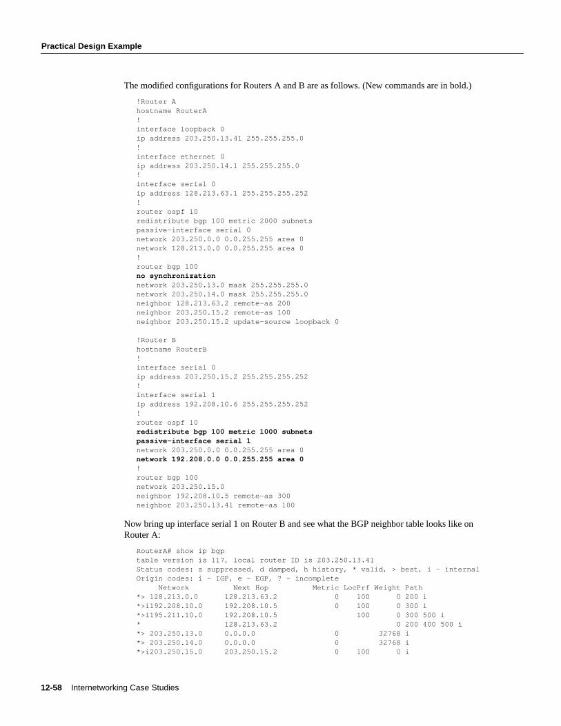
12-58 Internetworking Case Studies
Practical Design Example
The modified configurations for Routers A and B are as follows. (New commands are in bold.)
!Router Ahostname RouterA!interface loopback 0ip address 203.250.13.41 255.255.255.0!interface ethernet 0ip address 203.250.14.1 255.255.255.0!interface serial 0ip address 128.213.63.1 255.255.255.252!router ospf 10redistribute bgp 100 metric 2000 subnetspassive-interface serial 0network 203.250.0.0 0.0.255.255 area 0network 128.213.0.0 0.0.255.255 area 0!router bgp 100no synchronizationnetwork 203.250.13.0 mask 255.255.255.0network 203.250.14.0 mask 255.255.255.0neighbor 128.213.63.2 remote-as 200neighbor 203.250.15.2 remote-as 100neighbor 203.250.15.2 update-source loopback 0
!Router Bhostname RouterB!interface serial 0ip address 203.250.15.2 255.255.255.252!interface serial 1ip address 192.208.10.6 255.255.255.252!router ospf 10redistribute bgp 100 metric 1000 subnetspassive-interface serial 1network 203.250.0.0 0.0.255.255 area 0network 192.208.0.0 0.0.255.255 area 0!router bgp 100network 203.250.15.0neighbor 192.208.10.5 remote-as 300neighbor 203.250.13.41 remote-as 100
Now bring up interface serial 1 on Router B and see what the BGP neighbor table looks like onRouter A:
RouterA# show ip bgptable version is 117, local router ID is 203.250.13.41Status codes: s suppressed, d damped, h history, * valid, > best, i - internalOrigin codes: i - IGP, e - EGP, ? - incomplete Network Next Hop Metric LocPrf Weight Path*> 128.213.0.0 128.213.63.2 0 100 0 200 i*>i192.208.10.0 192.208.10.5 0 100 0 300 i*>i195.211.10.0 192.208.10.5 100 0 300 500 i* 128.213.63.2 0 200 400 500 i*> 203.250.13.0 0.0.0.0 0 32768 i*> 203.250.14.0 0.0.0.0 0 32768 i*>i203.250.15.0 203.250.15.2 0 100 0 i
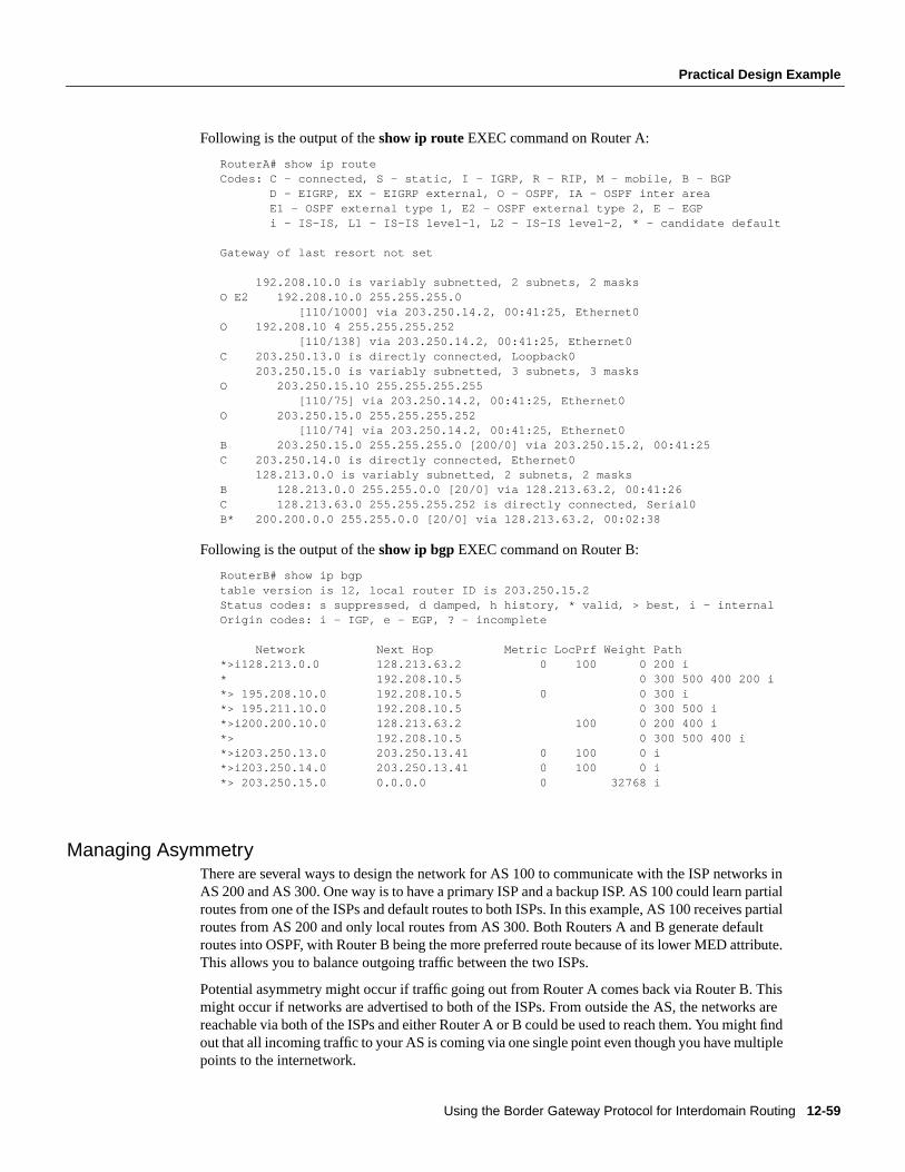
Using the Border Gateway Protocol for Interdomain Routing 12-59
Practical Design Example
Following is the output of theshow ip route EXEC command on Router A:
RouterA# show ip routeCodes: C - connected, S - static, I - IGRP, R - RIP, M - mobile, B - BGP D - EIGRP, EX - EIGRP external, O - OSPF, IA - OSPF inter area E1 - OSPF external type 1, E2 - OSPF external type 2, E - EGP i - IS-IS, L1 - IS-IS level-1, L2 - IS-IS level-2, * - candidate default
Gateway of last resort not set
192.208.10.0 is variably subnetted, 2 subnets, 2 masksO E2 192.208.10.0 255.255.255.0 [110/1000] via 203.250.14.2, 00:41:25, Ethernet0O 192.208.10 4 255.255.255.252 [110/138] via 203.250.14.2, 00:41:25, Ethernet0C 203.250.13.0 is directly connected, Loopback0 203.250.15.0 is variably subnetted, 3 subnets, 3 masksO 203.250.15.10 255.255.255.255 [110/75] via 203.250.14.2, 00:41:25, Ethernet0O 203.250.15.0 255.255.255.252 [110/74] via 203.250.14.2, 00:41:25, Ethernet0B 203.250.15.0 255.255.255.0 [200/0] via 203.250.15.2, 00:41:25C 203.250.14.0 is directly connected, Ethernet0 128.213.0.0 is variably subnetted, 2 subnets, 2 masksB 128.213.0.0 255.255.0.0 [20/0] via 128.213.63.2, 00:41:26C 128.213.63.0 255.255.255.252 is directly connected, Serial0B* 200.200.0.0 255.255.0.0 [20/0] via 128.213.63.2, 00:02:38
Following is the output of theshow ip bgp EXEC command on Router B:
RouterB# show ip bgptable version is 12, local router ID is 203.250.15.2Status codes: s suppressed, d damped, h history, * valid, > best, i - internalOrigin codes: i - IGP, e - EGP, ? - incomplete
Network Next Hop Metric LocPrf Weight Path*>i128.213.0.0 128.213.63.2 0 100 0 200 i* 192.208.10.5 0 300 500 400 200 i*> 195.208.10.0 192.208.10.5 0 0 300 i*> 195.211.10.0 192.208.10.5 0 300 500 i*>i200.200.10.0 128.213.63.2 100 0 200 400 i*> 192.208.10.5 0 300 500 400 i*>i203.250.13.0 203.250.13.41 0 100 0 i*>i203.250.14.0 203.250.13.41 0 100 0 i*> 203.250.15.0 0.0.0.0 0 32768 i
Managing AsymmetryThere are several ways to design the network for AS 100 to communicate with the ISP networks inAS 200 and AS 300. One way is to have a primary ISP and a backup ISP. AS 100 could learn partialroutes from one of the ISPs and default routes to both ISPs. In this example, AS 100 receives partialroutes from AS 200 and only local routes from AS 300. Both Routers A and B generate defaultroutes into OSPF, with Router B being the more preferred route because of its lower MED attribute.This allows you to balance outgoing traffic between the two ISPs.
Potential asymmetry might occur if traffic going out from Router A comes back via Router B. Thismight occur if networks are advertised to both of the ISPs. From outside the AS, the networks arereachable via both of the ISPs and either Router A or B could be used to reach them. You might findout that all incoming traffic to your AS is coming via one single point even though you have multiplepoints to the internetwork.
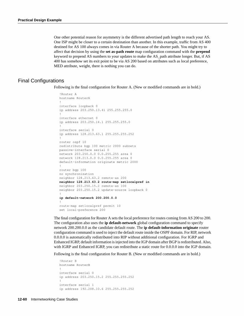
12-60 Internetworking Case Studies
Practical Design Example
One other potential reason for asymmetry is the different advertised path length to reach your AS.One ISP might be closer to a certain destination than another. In this example, traffic from AS 400destined for AS 100 always comes in via Router A because of the shorter path. You might try toaffect that decision by using theset as-path routemap configuration command with theprependkeyword to prepend AS numbers to your updates to make the AS_path attribute longer. But, if AS400 has somehow set its exit point to be via AS 200 based on attributes such as local preference,MED attribute, weight, there is nothing you can do.
Final ConfigurationsFollowing is the final configuration for Router A. (New or modified commands are in bold.)
!Router Ahostname RouterA!interface loopback 0ip address 203.250.13.41 255.255.255.0!interface ethernet 0ip address 203.250.14.1 255.255.255.0!interface serial 0ip address 128.213.63.1 255.255.255.252!router ospf 10redistribute bgp 100 metric 2000 subnetspassive-interface serial 0network 203.250.0.0 0.0.255.255 area 0network 128.213.0.0 0.0.255.255 area 0default-information originate metric 2000!router bgp 100no synchronizationneighbor 128.213.63.2 remote-as 200neighbor 128.213.63.2 route-map setlocalpref inneighbor 203.250.15.2 remote-as 100neighbor 203.250.15.2 update-source loopback 0!ip default-network 200.200.0.0!route-map setlocalpref permit 10set local-preference 200
The final configuration for Router A sets the local preference for routes coming from AS 200 to 200.The configuration also uses theip default-network global configuration command to specifynetwork 200.200.0.0 as the candidate default route. Theip default-information originate routerconfiguration command is used to inject the default route inside the OSPF domain. For RIP, network0.0.0.0 is automatically redistributed into RIP without additional configuration. For IGRP andEnhanced IGRP, default information is injected into the IGP domain after BGP is redistributed. Also,with IGRP and Enhanced IGRP, you can redistribute a static route for 0.0.0.0 into the IGP domain.
Following is the final configuration for Router B. (New or modified commands are in bold.)
!Router Bhostname RouterB!interface serial 0ip address 203.250.15.2 255.255.255.252!interface serial 1ip address 192.208.10.6 255.255.255.252
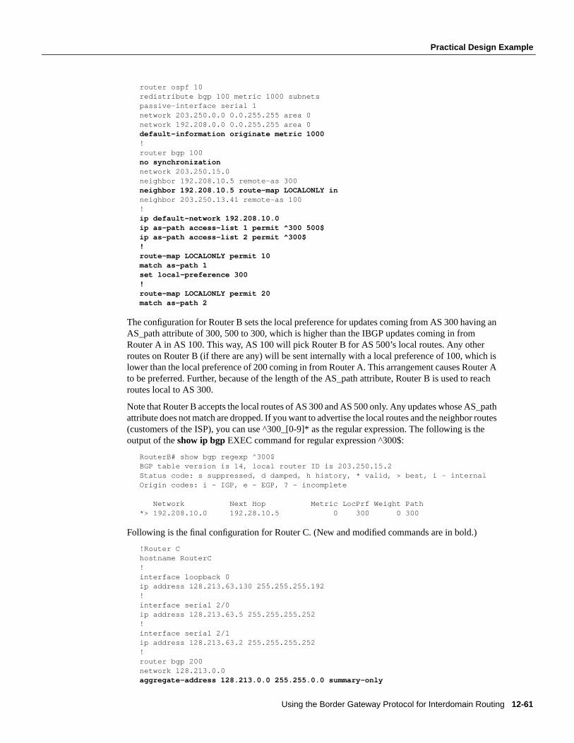
Using the Border Gateway Protocol for Interdomain Routing 12-61
Practical Design Example
router ospf 10redistribute bgp 100 metric 1000 subnetspassive-interface serial 1network 203.250.0.0 0.0.255.255 area 0network 192.208.0.0 0.0.255.255 area 0default-information originate metric 1000!router bgp 100no synchronizationnetwork 203.250.15.0neighbor 192.208.10.5 remote-as 300neighbor 192.208.10.5 route-map LOCALONLY inneighbor 203.250.13.41 remote-as 100!ip default-network 192.208.10.0ip as-path access-list 1 permit ^300 500$ip as-path access-list 2 permit ^300$!route-map LOCALONLY permit 10match as-path 1set local-preference 300!route-map LOCALONLY permit 20match as-path 2
The configuration for Router B sets the local preference for updates coming from AS 300 having anAS_path attribute of 300, 500 to 300, which is higher than the IBGP updates coming in fromRouter A in AS 100. This way, AS 100 will pick Router B for AS 500’s local routes. Any otherroutes on Router B (if there are any) will be sent internally with a local preference of 100, which islower than the local preference of 200 coming in from Router A. This arrangement causes Router Ato be preferred. Further, because of the length of the AS_path attribute, Router B is used to reachroutes local to AS 300.
Note that Router B accepts the local routes of AS 300 and AS 500 only. Any updates whose AS_pathattribute does not match are dropped. If you want to advertise the local routes and the neighbor routes(customers of the ISP), you can use ^300_[0-9]* as the regular expression. The following is theoutput of theshow ip bgp EXEC command for regular expression ^300$:
RouterB# show bgp regexp ^300$BGP table version is 14, local router ID is 203.250.15.2Status code: s suppressed, d damped, h history, * valid, > best, i - internalOrigin codes: i - IGP, e - EGP, ? - incomplete
Network Next Hop Metric LocPrf Weight Path*> 192.208.10.0 192.28.10.5 0 300 0 300
Following is the final configuration for Router C. (New and modified commands are in bold.)
!Router Chostname RouterC!interface loopback 0ip address 128.213.63.130 255.255.255.192!interface serial 2/0ip address 128.213.63.5 255.255.255.252!interface serial 2/1ip address 128.213.63.2 255.255.255.252!router bgp 200network 128.213.0.0aggregate-address 128.213.0.0 255.255.0.0 summary-only
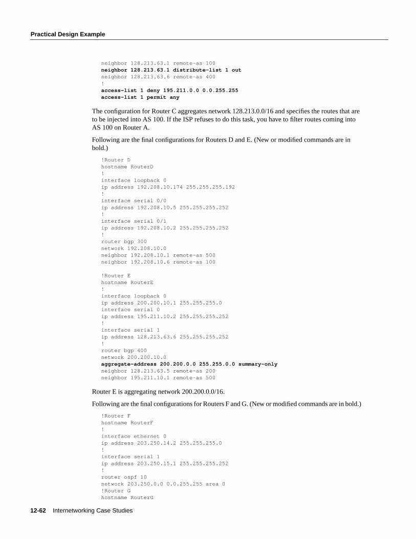
12-62 Internetworking Case Studies
Practical Design Example
neighbor 128.213.63.1 remote-as 100neighbor 128.213.63.1 distribute-list 1 outneighbor 128.213.63.6 remote-as 400!access-list 1 deny 195.211.0.0 0.0.255.255access-list 1 permit any
The configuration for Router C aggregates network 128.213.0.0/16 and specifies the routes that areto be injected into AS 100. If the ISP refuses to do this task, you have to filter routes coming intoAS 100 on Router A.
Following are the final configurations for Routers D and E. (New or modified commands are inbold.)
!Router Dhostname RouterD!interface loopback 0ip address 192.208.10.174 255.255.255.192!interface serial 0/0ip address 192.208.10.5 255.255.255.252!interface serial 0/1ip address 192.208.10.2 255.255.255.252!router bgp 300network 192.208.10.0neighbor 192.208.10.1 remote-as 500neighbor 192.208.10.6 remote-as 100
!Router Ehostname RouterE!interface loopback 0ip address 200.200.10.1 255.255.255.0interface serial 0ip address 195.211.10.2 255.255.255.252!interface serial 1ip address 128.213.63.6 255.255.255.252!router bgp 400network 200.200.10.0aggregate-address 200.200.0.0 255.255.0.0 summary-onlyneighbor 128.213.63.5 remote-as 200neighbor 195.211.10.1 remote-as 500
Router E is aggregating network 200.200.0.0/16.
Following are the final configurations for Routers F and G. (New or modified commands are in bold.)
!Router Fhostname RouterF!interface ethernet 0ip address 203.250.14.2 255.255.255.0!interface serial 1ip address 203.250.15.1 255.255.255.252!router ospf 10network 203.250.0.0 0.0.255.255 area 0!Router Ghostname RouterG
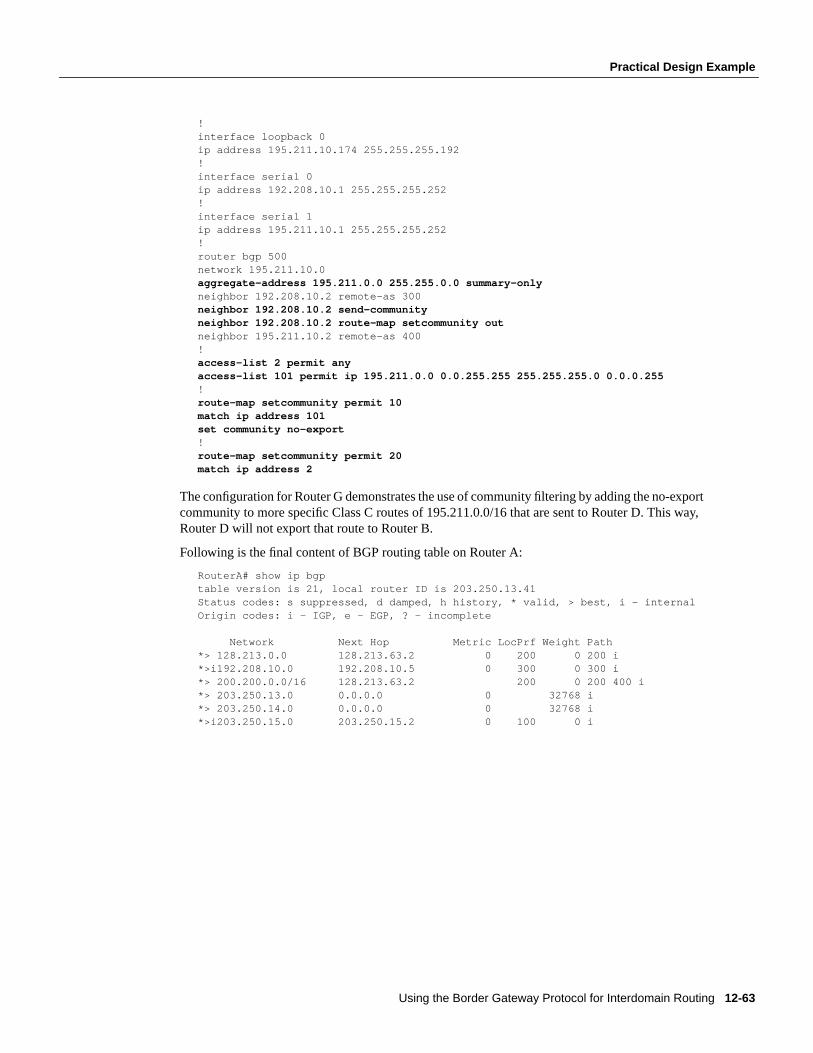
Using the Border Gateway Protocol for Interdomain Routing 12-63
Practical Design Example
!interface loopback 0ip address 195.211.10.174 255.255.255.192!interface serial 0ip address 192.208.10.1 255.255.255.252!interface serial 1ip address 195.211.10.1 255.255.255.252!router bgp 500network 195.211.10.0aggregate-address 195.211.0.0 255.255.0.0 summary-onlyneighbor 192.208.10.2 remote-as 300neighbor 192.208.10.2 send-communityneighbor 192.208.10.2 route-map setcommunity outneighbor 195.211.10.2 remote-as 400!access-list 2 permit anyaccess-list 101 permit ip 195.211.0.0 0.0.255.255 255.255.255.0 0.0.0.255!route-map setcommunity permit 10match ip address 101set community no-export!route-map setcommunity permit 20match ip address 2
The configuration for Router G demonstrates the use of community filtering by adding the no-exportcommunity to more specific Class C routes of 195.211.0.0/16 that are sent to Router D. This way,Router D will not export that route to Router B.
Following is the final content of BGP routing table on Router A:
RouterA# show ip bgptable version is 21, local router ID is 203.250.13.41Status codes: s suppressed, d damped, h history, * valid, > best, i - internalOrigin codes: i - IGP, e - EGP, ? - incomplete
Network Next Hop Metric LocPrf Weight Path*> 128.213.0.0 128.213.63.2 0 200 0 200 i*>i192.208.10.0 192.208.10.5 0 300 0 300 i*> 200.200.0.0/16 128.213.63.2 200 0 200 400 i*> 203.250.13.0 0.0.0.0 0 32768 i*> 203.250.14.0 0.0.0.0 0 32768 i*>i203.250.15.0 203.250.15.2 0 100 0 i
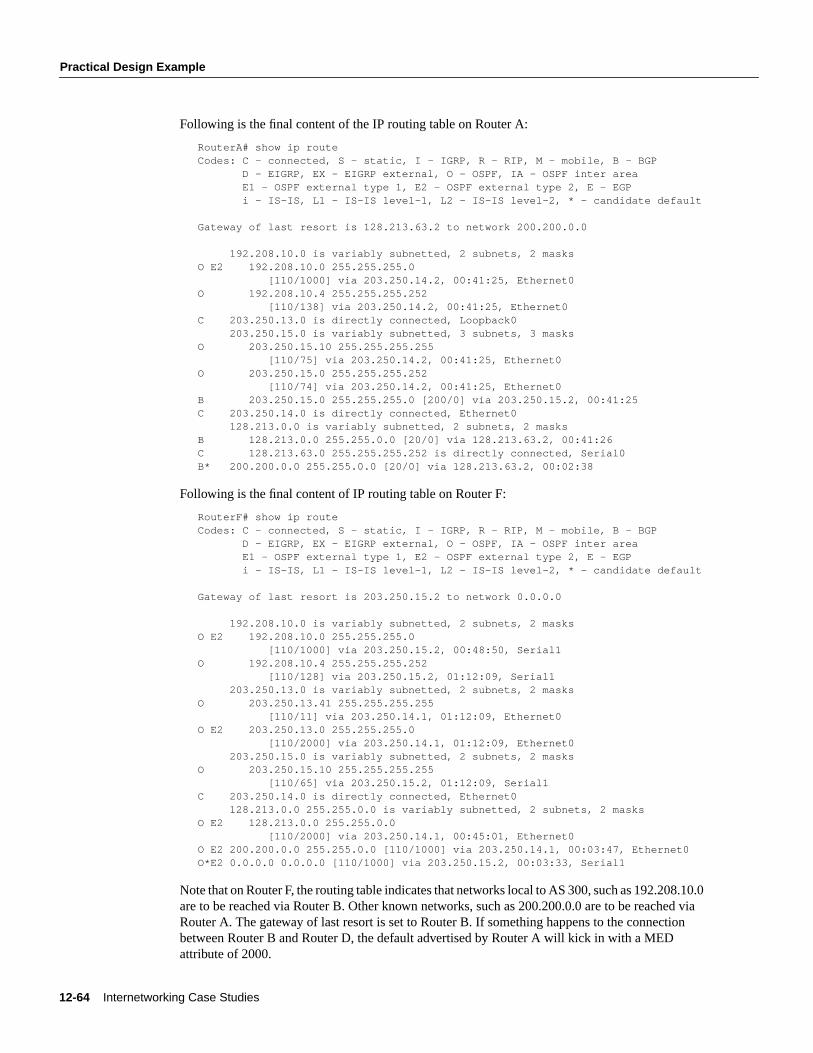
12-64 Internetworking Case Studies
Practical Design Example
Following is the final content of the IP routing table on Router A:
RouterA# show ip routeCodes: C - connected, S - static, I - IGRP, R - RIP, M - mobile, B - BGP D - EIGRP, EX - EIGRP external, O - OSPF, IA - OSPF inter area E1 - OSPF external type 1, E2 - OSPF external type 2, E - EGP i - IS-IS, L1 - IS-IS level-1, L2 - IS-IS level-2, * - candidate default
Gateway of last resort is 128.213.63.2 to network 200.200.0.0
192.208.10.0 is variably subnetted, 2 subnets, 2 masksO E2 192.208.10.0 255.255.255.0 [110/1000] via 203.250.14.2, 00:41:25, Ethernet0O 192.208.10.4 255.255.255.252 [110/138] via 203.250.14.2, 00:41:25, Ethernet0C 203.250.13.0 is directly connected, Loopback0 203.250.15.0 is variably subnetted, 3 subnets, 3 masksO 203.250.15.10 255.255.255.255 [110/75] via 203.250.14.2, 00:41:25, Ethernet0O 203.250.15.0 255.255.255.252 [110/74] via 203.250.14.2, 00:41:25, Ethernet0B 203.250.15.0 255.255.255.0 [200/0] via 203.250.15.2, 00:41:25C 203.250.14.0 is directly connected, Ethernet0 128.213.0.0 is variably subnetted, 2 subnets, 2 masksB 128.213.0.0 255.255.0.0 [20/0] via 128.213.63.2, 00:41:26C 128.213.63.0 255.255.255.252 is directly connected, Serial0B* 200.200.0.0 255.255.0.0 [20/0] via 128.213.63.2, 00:02:38
Following is the final content of IP routing table on Router F:
RouterF# show ip routeCodes: C - connected, S - static, I - IGRP, R - RIP, M - mobile, B - BGP D - EIGRP, EX - EIGRP external, O - OSPF, IA - OSPF inter area E1 - OSPF external type 1, E2 - OSPF external type 2, E - EGP i - IS-IS, L1 - IS-IS level-1, L2 - IS-IS level-2, * - candidate default
Gateway of last resort is 203.250.15.2 to network 0.0.0.0
192.208.10.0 is variably subnetted, 2 subnets, 2 masksO E2 192.208.10.0 255.255.255.0 [110/1000] via 203.250.15.2, 00:48:50, Serial1O 192.208.10.4 255.255.255.252 [110/128] via 203.250.15.2, 01:12:09, Serial1 203.250.13.0 is variably subnetted, 2 subnets, 2 masksO 203.250.13.41 255.255.255.255 [110/11] via 203.250.14.1, 01:12:09, Ethernet0O E2 203.250.13.0 255.255.255.0 [110/2000] via 203.250.14.1, 01:12:09, Ethernet0 203.250.15.0 is variably subnetted, 2 subnets, 2 masksO 203.250.15.10 255.255.255.255 [110/65] via 203.250.15.2, 01:12:09, Serial1C 203.250.14.0 is directly connected, Ethernet0 128.213.0.0 255.255.0.0 is variably subnetted, 2 subnets, 2 masksO E2 128.213.0.0 255.255.0.0 [110/2000] via 203.250.14.1, 00:45:01, Ethernet0O E2 200.200.0.0 255.255.0.0 [110/1000] via 203.250.14.1, 00:03:47, Ethernet0O*E2 0.0.0.0 0.0.0.0 [110/1000] via 203.250.15.2, 00:03:33, Serial1
Note that on Router F, the routing table indicates that networks local to AS 300, such as 192.208.10.0are to be reached via Router B. Other known networks, such as 200.200.0.0 are to be reached viaRouter A. The gateway of last resort is set to Router B. If something happens to the connectionbetween Router B and Router D, the default advertised by Router A will kick in with a MEDattribute of 2000.
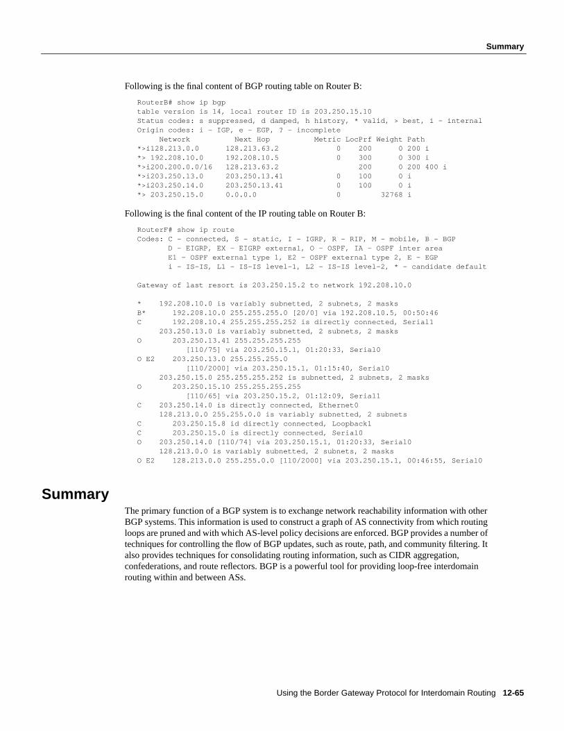
Using the Border Gateway Protocol for Interdomain Routing 12-65
Summary
Following is the final content of BGP routing table on Router B:
RouterB# show ip bgptable version is 14, local router ID is 203.250.15.10Status codes: s suppressed, d damped, h history, * valid, > best, i - internalOrigin codes: i - IGP, e - EGP, ? - incomplete Network Next Hop Metric LocPrf Weight Path*>i128.213.0.0 128.213.63.2 0 200 0 200 i*> 192.208.10.0 192.208.10.5 0 300 0 300 i*>i200.200.0.0/16 128.213.63.2 200 0 200 400 i*>i203.250.13.0 203.250.13.41 0 100 0 i*>i203.250.14.0 203.250.13.41 0 100 0 i*> 203.250.15.0 0.0.0.0 0 32768 i
Following is the final content of the IP routing table on Router B:
RouterF# show ip routeCodes: C - connected, S - static, I - IGRP, R - RIP, M - mobile, B - BGP D - EIGRP, EX - EIGRP external, O - OSPF, IA - OSPF inter area E1 - OSPF external type 1, E2 - OSPF external type 2, E - EGP i - IS-IS, L1 - IS-IS level-1, L2 - IS-IS level-2, * - candidate default
Gateway of last resort is 203.250.15.2 to network 192.208.10.0
* 192.208.10.0 is variably subnetted, 2 subnets, 2 masksB* 192.208.10.0 255.255.255.0 [20/0] via 192.208.10.5, 00:50:46C 192.208.10.4 255.255.255.252 is directly connected, Serial1 203.250.13.0 is variably subnetted, 2 subnets, 2 masksO 203.250.13.41 255.255.255.255 [110/75] via 203.250.15.1, 01:20:33, Serial0O E2 203.250.13.0 255.255.255.0 [110/2000] via 203.250.15.1, 01:15:40, Serial0 203.250.15.0 255.255.255.252 is subnetted, 2 subnets, 2 masksO 203.250.15.10 255.255.255.255 [110/65] via 203.250.15.2, 01:12:09, Serial1C 203.250.14.0 is directly connected, Ethernet0 128.213.0.0 255.255.0.0 is variably subnetted, 2 subnetsC 203.250.15.8 id directly connected, Loopback1C 203.250.15.0 is directly connected, Serial0O 203.250.14.0 [110/74] via 203.250.15.1, 01:20:33, Serial0 128.213.0.0 is variably subnetted, 2 subnets, 2 masksO E2 128.213.0.0 255.255.0.0 [110/2000] via 203.250.15.1, 00:46:55, Serial0
SummaryThe primary function of a BGP system is to exchange network reachability information with otherBGP systems. This information is used to construct a graph of AS connectivity from which routingloops are pruned and with which AS-level policy decisions are enforced. BGP provides a number oftechniques for controlling the flow of BGP updates, such as route, path, and community filtering. Italso provides techniques for consolidating routing information, such as CIDR aggregation,confederations, and route reflectors. BGP is a powerful tool for providing loop-free interdomainrouting within and between ASs.

12-66 Internetworking Case Studies
Summary


![15-744: Computer Networking L-3 BGP. 2 Next Lecture: Interdomain Routing BGP Assigned Reading MIT BGP Class Notes [Gao00] On Inferring Autonomous System](https://img.pdfslide.us/doc/110x75/56649d2d5503460f94a04b7a/15-744-computer-networking-l-3-bgp-2-next-lecture-interdomain-routing-bgp.jpg)