Embed Size (px)
Citation preview

Using Test Equipment to Detect and Measure
Power Quality Issues
PQ03
Related Presentations:
PQ01 – Harmonic Solutions for VFD’s
PQ02 - Power Quality and Monitoring with
iSense/iGrid/DySC & Surge/Sag/Transient Protection
2
Power Quality
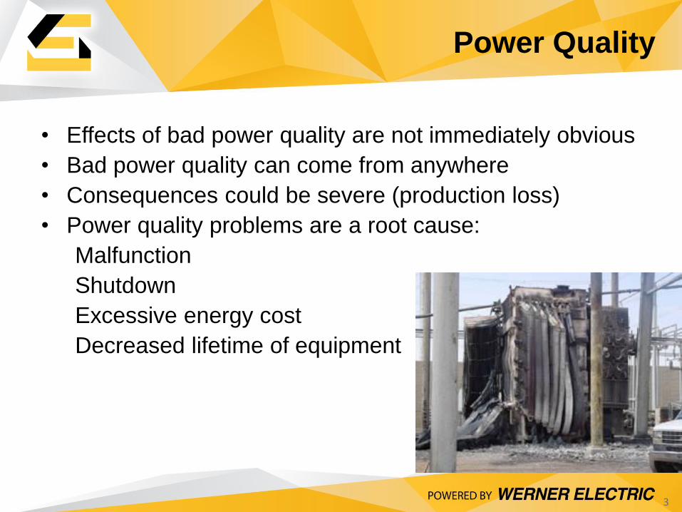
• Effects of bad power quality are not immediately obvious
• Bad power quality can come from anywhere
• Consequences could be severe (production loss)
• Power quality problems are a root cause:
Malfunction
Shutdown
Excessive energy cost
Decreased lifetime of equipment
3
Power Quality
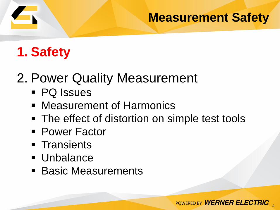
1. Safety
2. Power Quality Measurement PQ Issues
Measurement of Harmonics
The effect of distortion on simple test tools
Power Factor
Transients
Unbalance
Basic Measurements
4
Measurement Safety
5
Measurement Safety
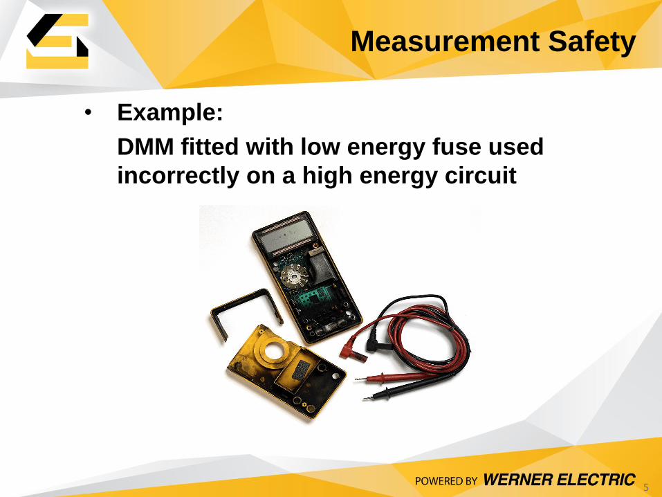
• Example:
DMM fitted with low energy fuse used
incorrectly on a high energy circuit
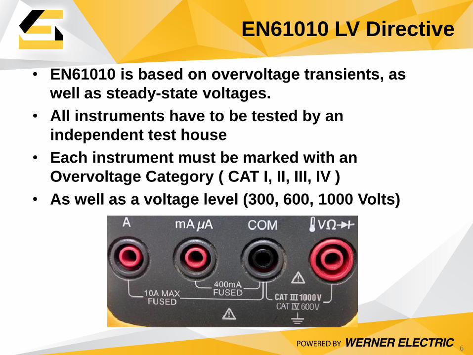
• EN61010 is based on overvoltage transients, as
well as steady-state voltages.
• All instruments have to be tested by an
independent test house
• Each instrument must be marked with an
Overvoltage Category ( CAT I, II, III, IV )
• As well as a voltage level (300, 600, 1000 Volts)
6
EN61010 LV Directive
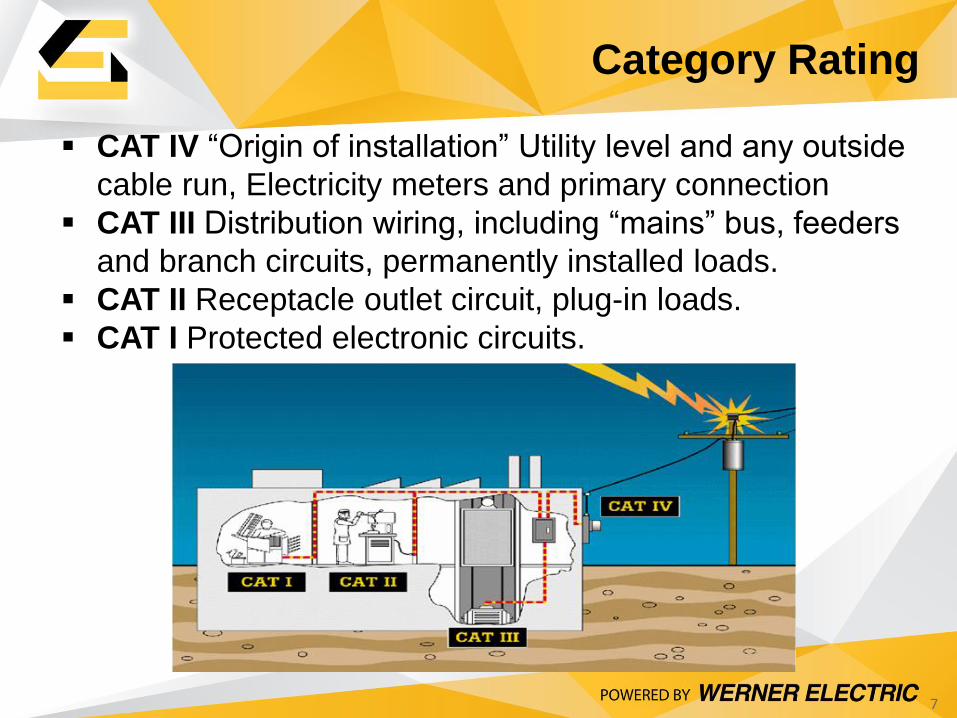
CAT IV “Origin of installation” Utility level and any outside
cable run, Electricity meters and primary connection
CAT III Distribution wiring, including “mains” bus, feeders
and branch circuits, permanently installed loads.
CAT II Receptacle outlet circuit, plug-in loads.
CAT I Protected electronic circuits.
7
Category Rating
8
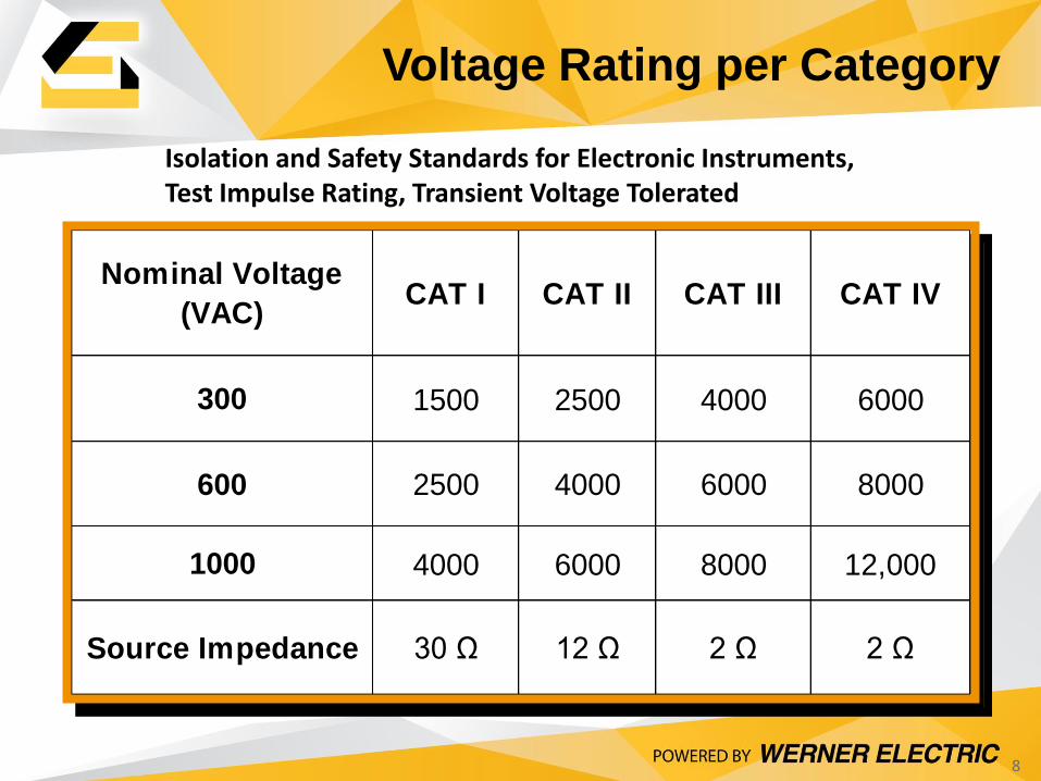
Voltage Rating per Category
Nominal Voltage
(VAC)CAT I CAT II CAT III CAT IV
300 1500 2500 4000 6000
600 2500 4000 6000 8000
1000 4000 6000 8000 12,000
Source Impedance 30 Ω 12 Ω 2 Ω 2 Ω
Isolation and Safety Standards for Electronic Instruments, Test Impulse Rating, Transient Voltage Tolerated
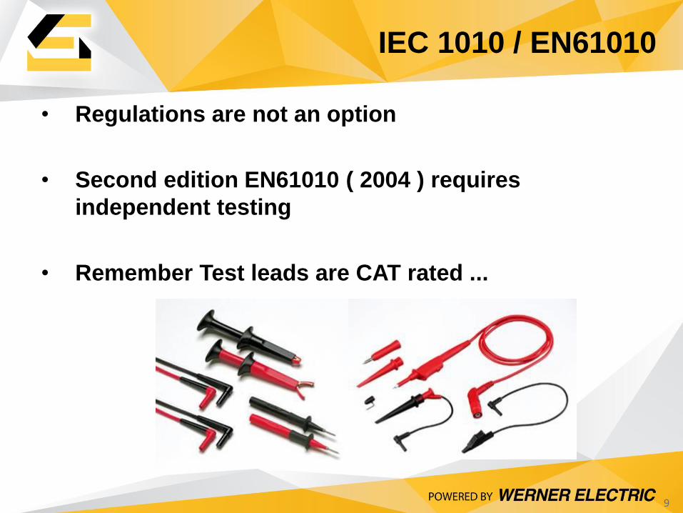
• Regulations are not an option
• Second edition EN61010 ( 2004 ) requires
independent testing
• Remember Test leads are CAT rated ...
9
IEC 1010 / EN61010
1. Safety
2. Power Quality Measurement PQ Issues
Measurement of Harmonics
The effect of distortion on simple test tools
Power Factor
Transients
Basic Measurements
10
PQ Measurement
• Lightning
• Non-Linear Loads – VFD’s, SMPS
• Capacitor switching transients
• Inrush Currents from Motors
• Sags, Surges
• Undersized Neutrals
• Electrical Noise
• Gen-Sets not sized for Harmonics
11
Power Quality Culprits
Fre
qu
ency
of
Occ
urr
ence
$ $$ $$$ $$$$
Low
V
ery
Low
M
ediu
m
Hig
h
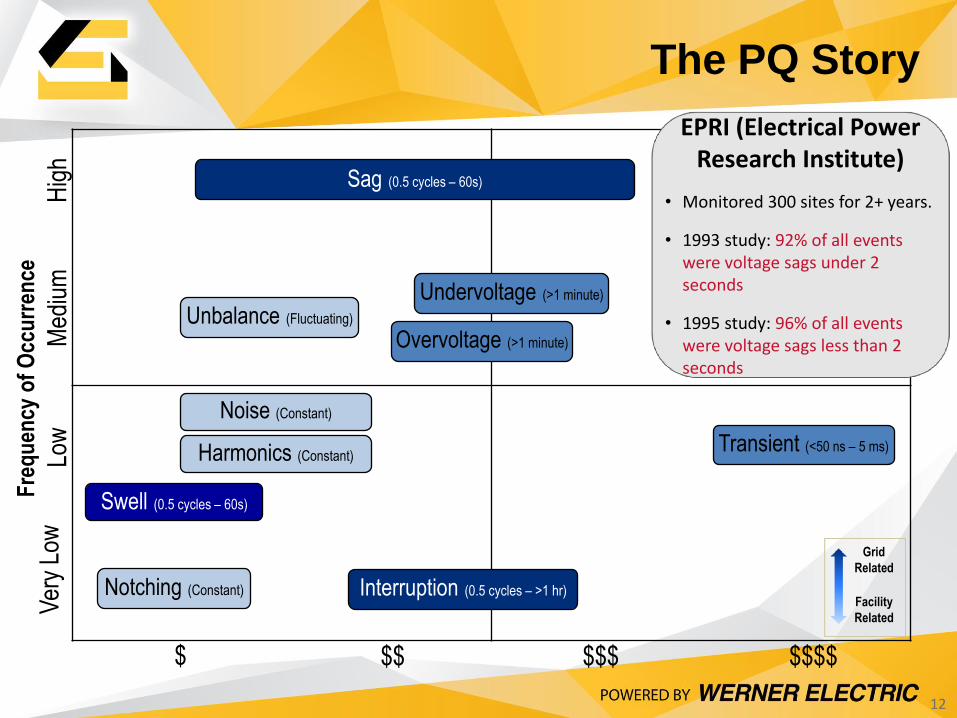
Notching (Constant)
Swell (0.5 cycles – 60s)
Noise (Constant)
Harmonics (Constant) Transient (<50 ns – 5 ms)
Unbalance (Fluctuating)
Undervoltage (>1 minute)
Overvoltage (>1 minute)
EPRI (Electrical Power Research Institute)
• Monitored 300 sites for 2+ years.
• 1993 study: 92% of all events were voltage sags under 2 seconds
• 1995 study: 96% of all events were voltage sags less than 2 seconds
Grid
Related
Facility
Related
Sag (0.5 cycles – 60s)
Interruption (0.5 cycles – >1 hr)
12
The PQ Story
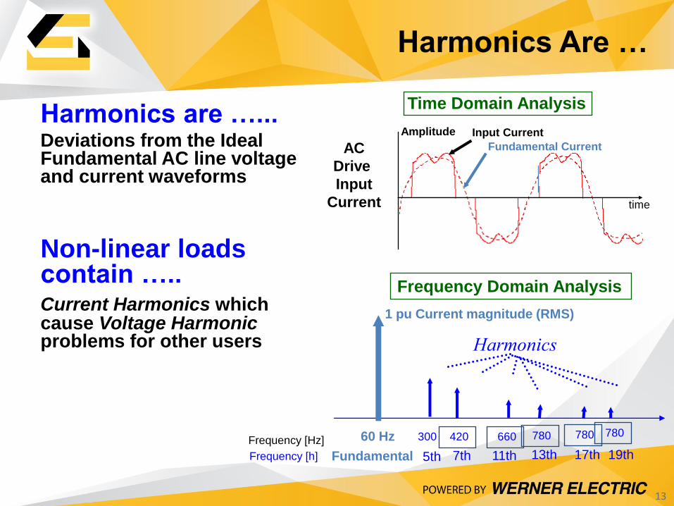
Harmonics are …... Deviations from the Ideal Fundamental AC line voltage and current waveforms
Non-linear loads contain ….. Current Harmonics which cause Voltage Harmonic problems for other users
AC
Drive
Input
Current
Input Current
Fundamental Current
Amplitude
time
Time Domain Analysis
Frequency Domain Analysis
1 pu Current magnitude (RMS)
60 Hz
Fundamental
Frequency [Hz] 300 420 660 780
Harmonics
5th 11th 7th 13th 19th 17th
780 780
Frequency [h]
13
Harmonics Are …
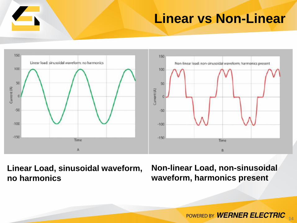
Linear Load, sinusoidal waveform,
no harmonics
Non-linear Load, non-sinusoidal
waveform, harmonics present
14
Linear vs Non-Linear
Non-linear Commercial loads
generally come from:
• Computers and CRT’s
• Electronic Ballasts
• And other single phase office equipment
Non-linear Industrial loads generally come from:
• Welders
• Arc furnaces
• UPS and DC power supplies
• AC & DC Drives
15
Non-Linear Loads
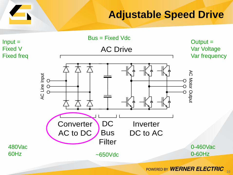
Converter
AC to DC
Inverter
DC to AC
DC
Bus
Filter
AC DriveA
C M
oto
r Outp
utA
C L
ine I
nput
Input =
Fixed V
Fixed freq
Output =
Var Voltage
Var frequency
480Vac
60Hz
0-460Vac
0-60Hz ~650Vdc
Bus = Fixed Vdc
16
Adjustable Speed Drive
Harmonic Measurement of Current
Waveform
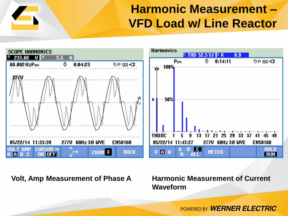
Volt, Amp Measurement of Phase A
Harmonic Measurement –
VFD Load w/ Line Reactor
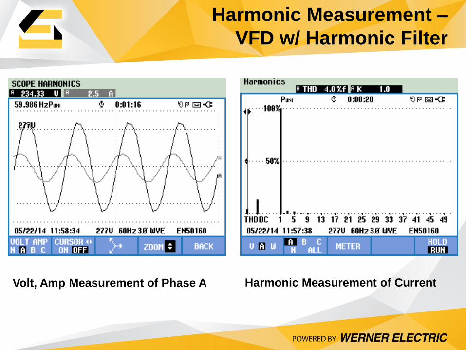
Volt, Amp Measurement of Phase A Harmonic Measurement of Current
Harmonic Measurement –
VFD w/ Harmonic Filter
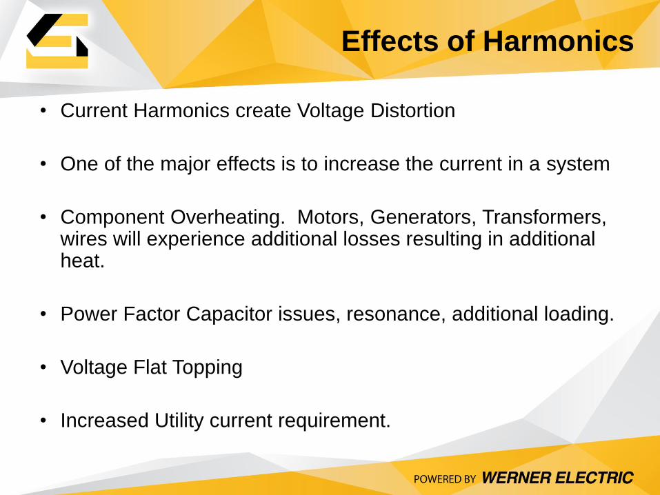
Effects of Harmonics
• Current Harmonics create Voltage Distortion
• One of the major effects is to increase the current in a system
• Component Overheating. Motors, Generators, Transformers, wires will experience additional losses resulting in additional heat.
• Power Factor Capacitor issues, resonance, additional loading.
• Voltage Flat Topping
• Increased Utility current requirement.
For troubleshooting:
• Check the harmonics present
• Check for the levels of the harmonics
• Look for recognizable patterns
Harmonics Troubleshooting
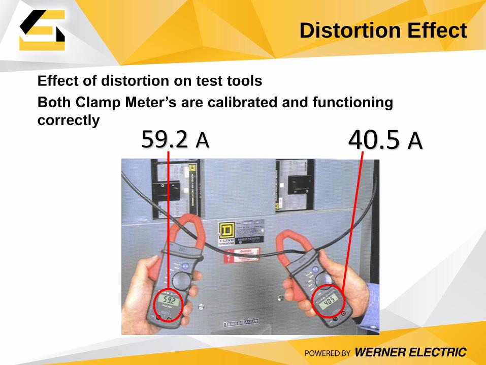
Effect of distortion on test tools
Both Clamp Meter’s are calibrated and functioning
correctly
59.2 A 40.5 A
Distortion Effect
True RMS Measurement
True RMS / Harmonics
A True RMS meter calculates the effective
heating value of the distorted waveform.
This will include all harmonics.
“RMS” stands for root-mean-square.
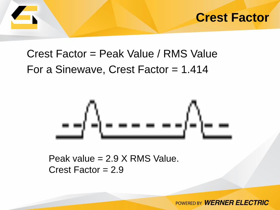
Crest Factor = Peak Value / RMS Value
For a Sinewave, Crest Factor = 1.414
RMS
Peak
Peak value = 2.9 X RMS Value.
Crest Factor = 2.9
Crest Factor
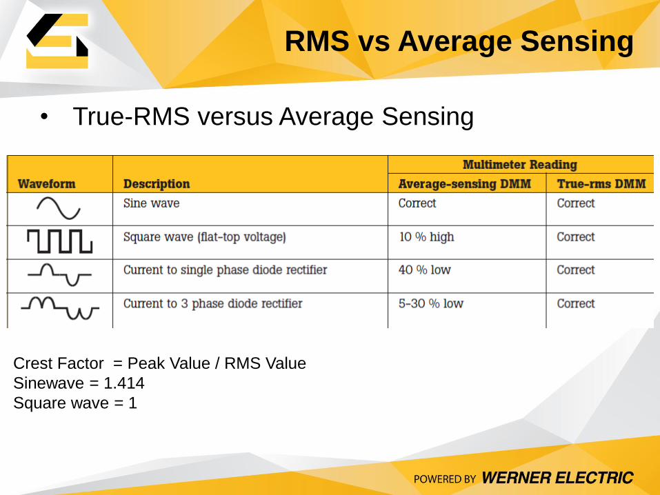
RMS vs Average Sensing
• True-RMS versus Average Sensing
Crest Factor = Peak Value / RMS Value
Sinewave = 1.414
Square wave = 1
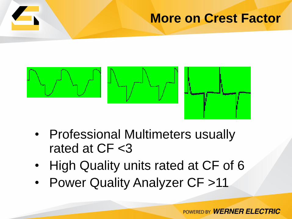
• Professional Multimeters usually rated at CF <3
• High Quality units rated at CF of 6
• Power Quality Analyzer CF >11
C.F. = 1.43 C.F. = 2.39 C.F. = 4.68
More on Crest Factor
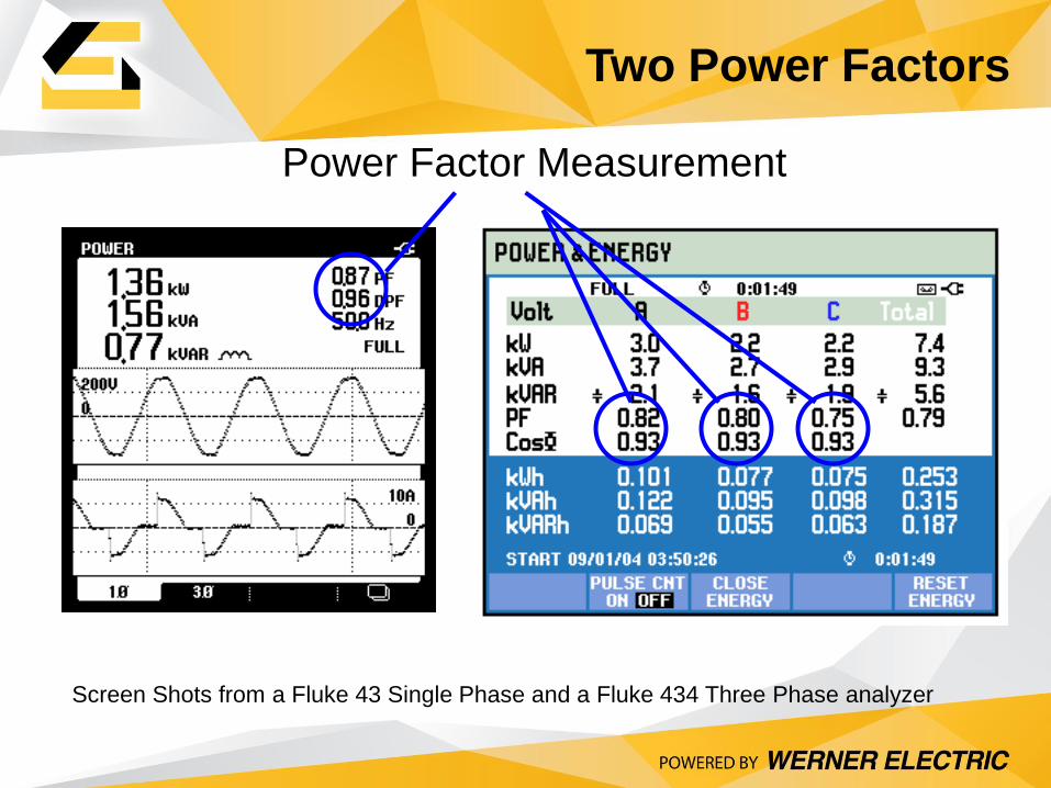
Power Factor Measurement
Screen Shots from a Fluke 43 Single Phase and a Fluke 434 Three Phase analyzer
Two Power Factors
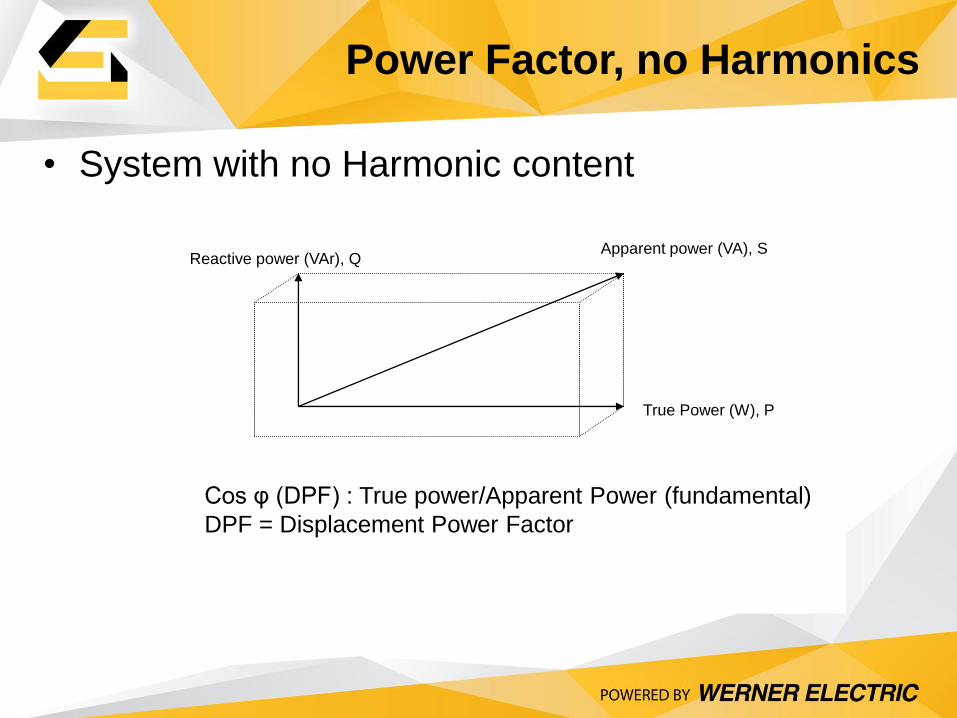
• System with no Harmonic content
True Power (W), P
Reactive power (VAr), Q
Cos φ (DPF) : True power/Apparent Power (fundamental)
DPF = Displacement Power Factor
Apparent power (VA), S
Power Factor, no Harmonics
28
HARMONIC
Current
Ireact
Ireal
Ifund
Itotal
Iharm
(in phase with
line-to-neutral
voltage, VLN)
REACTIVE
Current
Q
P
S1
S
D
x-axis
y-axis
z-axis
REAL
Current
222 DQPS
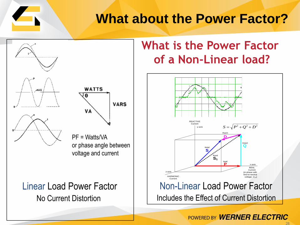
What is the Power Factor
of a Non-Linear load?
Linear Load Power Factor Non-Linear Load Power Factor
No Current Distortion Includes the Effect of Current Distortion
PF = Watts/VA
or phase angle between
voltage and current
What about the Power Factor?
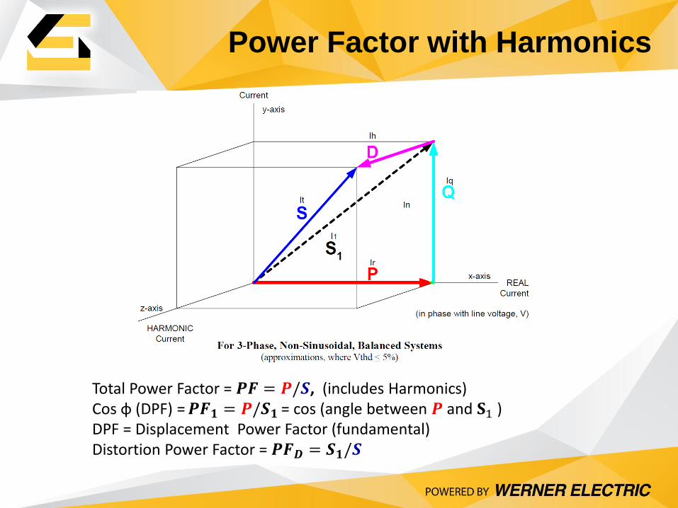
Power Factor with Harmonics
Total Power Factor = 𝑷𝑭 = 𝑷/𝑺, (includes Harmonics)
Cos φ (DPF) = 𝑷𝑭𝟏 = 𝑷/𝑺𝟏 = cos (angle between 𝑷 and 𝐒1 )
DPF = Displacement Power Factor (fundamental) Distortion Power Factor = 𝑷𝑭𝑫 = 𝑺𝟏/𝑺
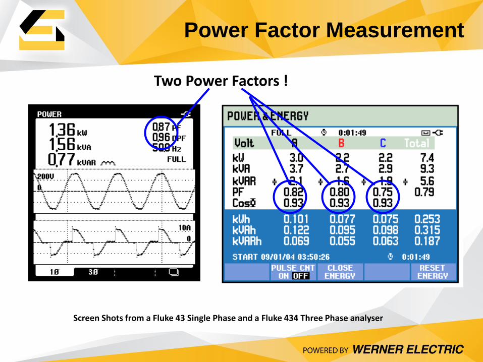
Screen Shots from a Fluke 43 Single Phase and a Fluke 434 Three Phase analyser
Two Power Factors !
Power Factor Measurement
31
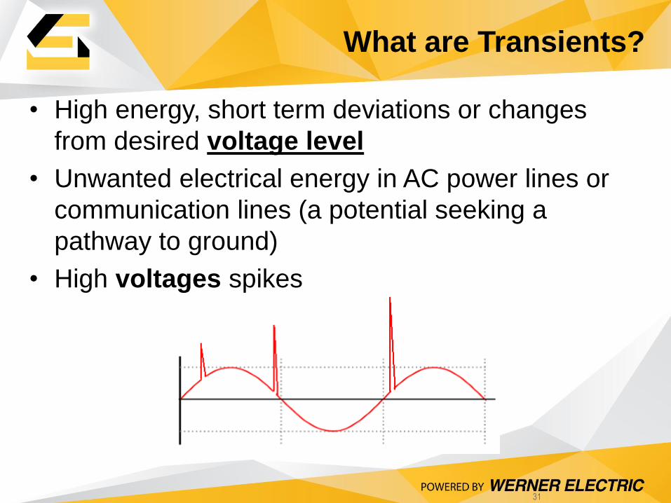
• High energy, short term deviations or changes
from desired voltage level
• Unwanted electrical energy in AC power lines or
communication lines (a potential seeking a
pathway to ground)
• High voltages spikes
What are Transients?
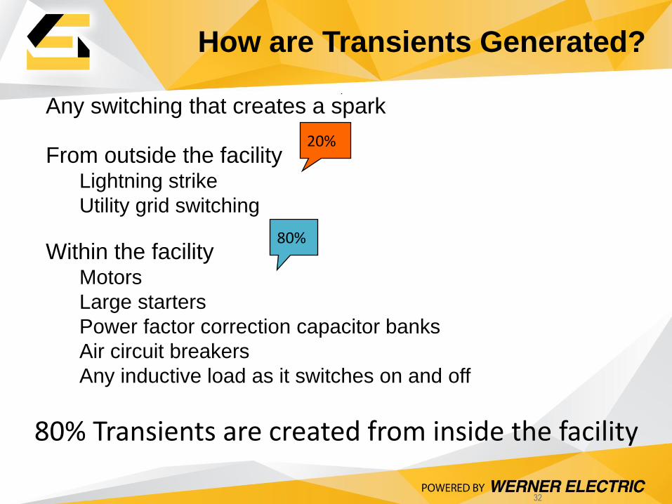
32
Any switching that creates a spark
From outside the facility Lightning strike
Utility grid switching
Within the facility Motors
Large starters
Power factor correction capacitor banks
Air circuit breakers
Any inductive load as it switches on and off
80%
20%
80% Transients are created from inside the facility
How are Transients Generated?
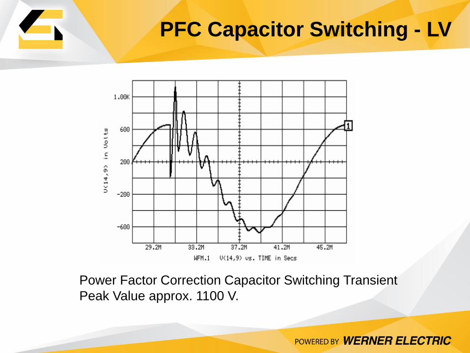
Power Factor Correction Capacitor Switching Transient
Peak Value approx. 1100 V.
PFC Capacitor Switching - LV
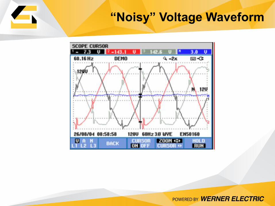
“Noisy” Voltage Waveform
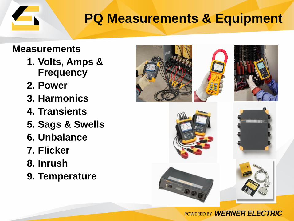
Measurements
1. Volts, Amps & Frequency
2. Power
3. Harmonics
4. Transients
5. Sags & Swells
6. Unbalance
7. Flicker
8. Inrush
9. Temperature
PQ Measurements & Equipment
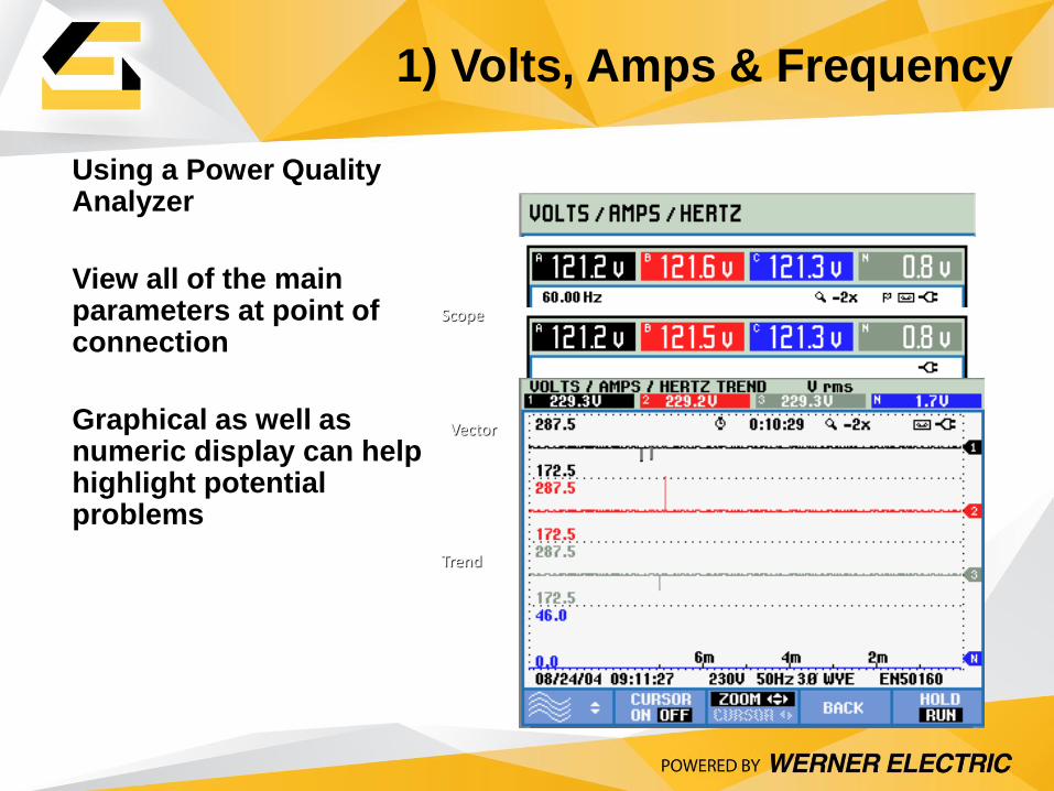
Using a Power Quality Analyzer
View all of the main parameters at point of connection
Graphical as well as numeric display can help highlight potential problems
Scope
Vector
Trend
1) Volts, Amps & Frequency
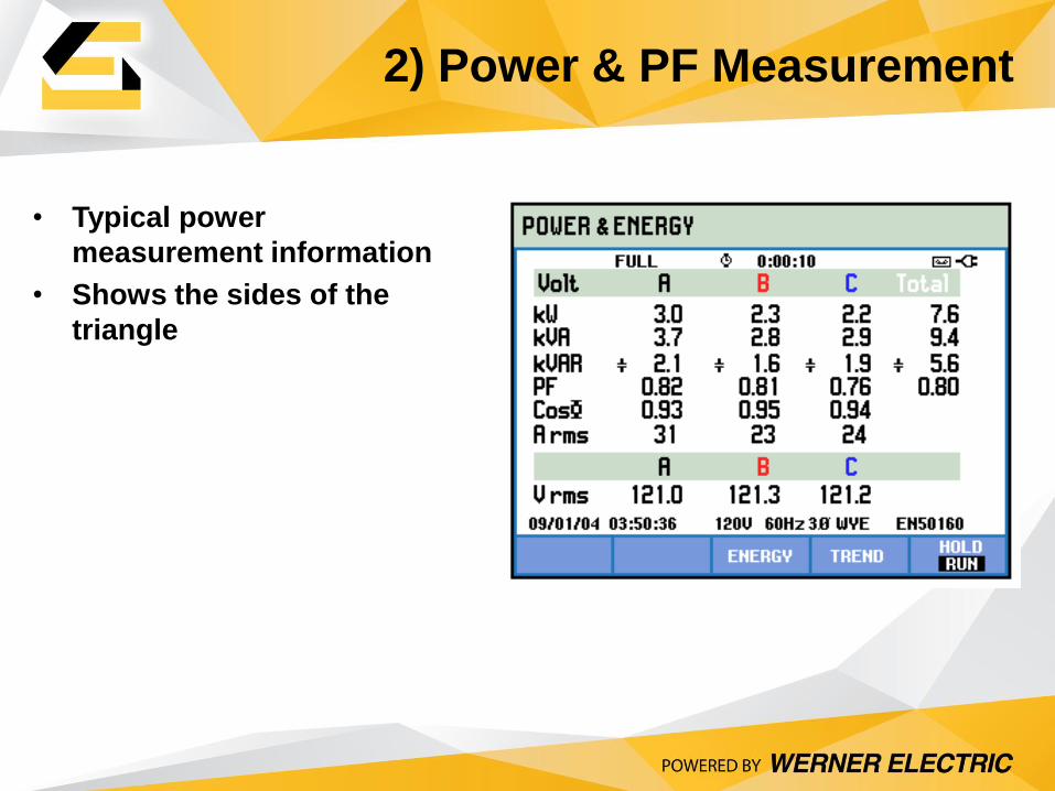
• Typical power
measurement information
• Shows the sides of the
triangle
2) Power & PF Measurement
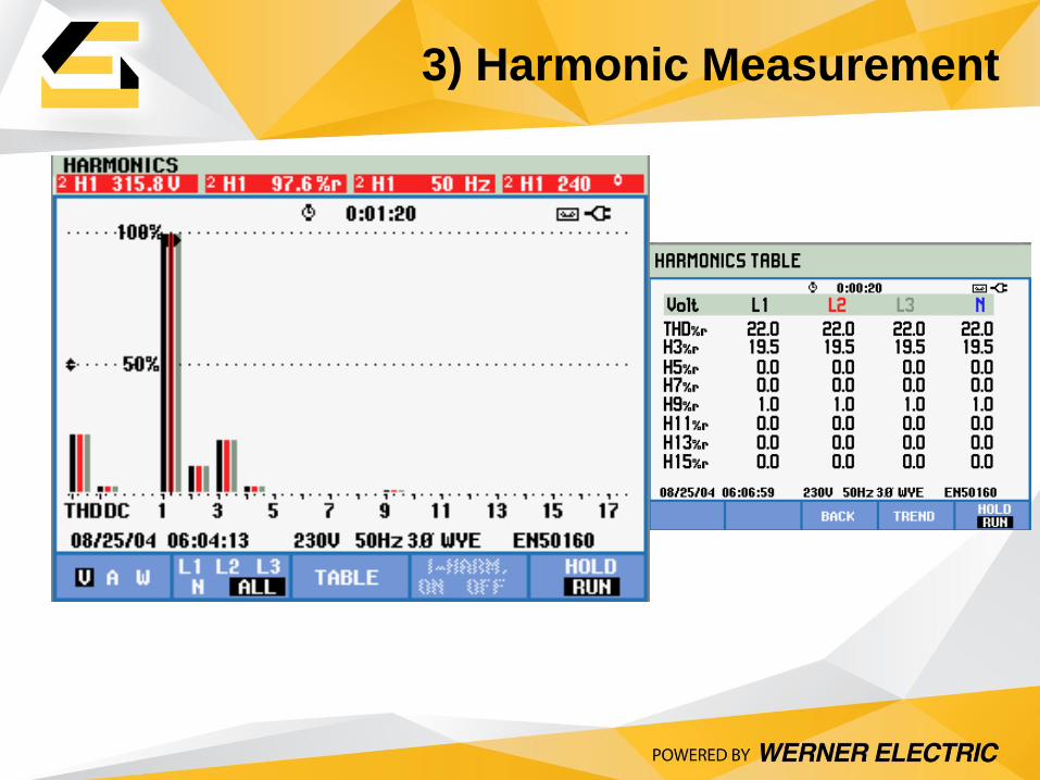
3) Harmonic Measurement
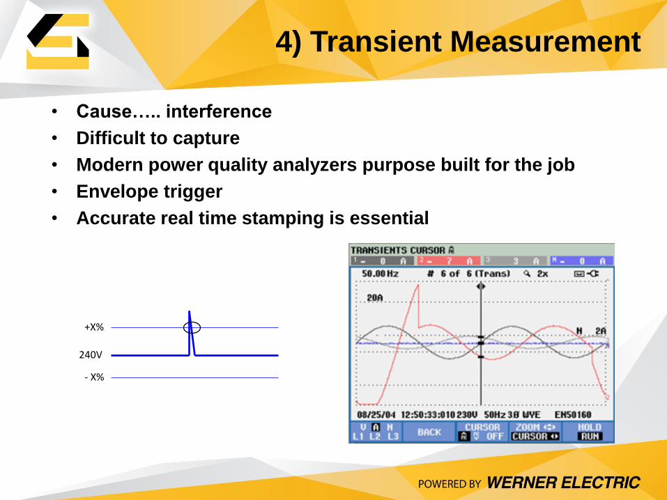
• Cause….. interference
• Difficult to capture
• Modern power quality analyzers purpose built for the job
• Envelope trigger
• Accurate real time stamping is essential
240V
+X%
- X%
4) Transient Measurement
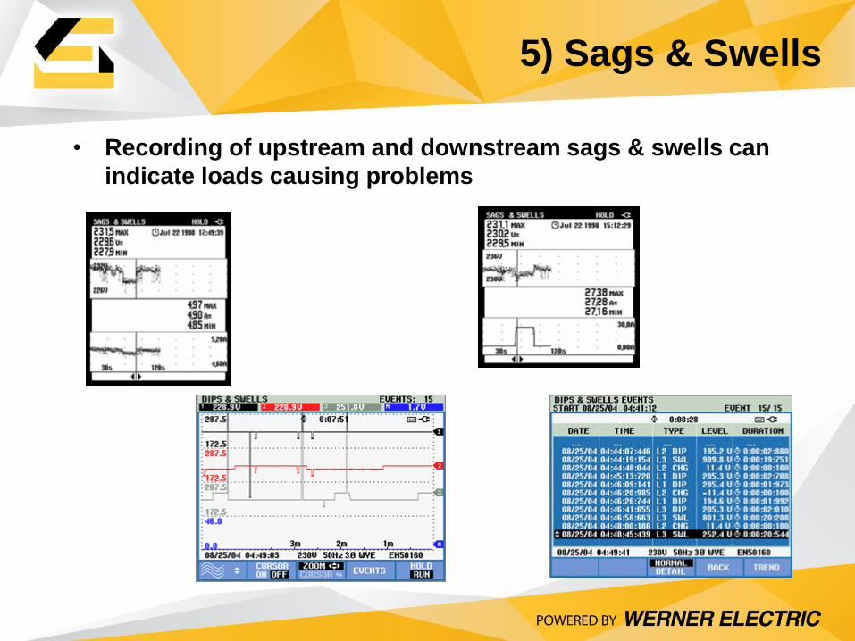
• Recording of upstream and downstream sags & swells can
indicate loads causing problems
Upstream Sag Downstream Sag
5) Sags & Swells
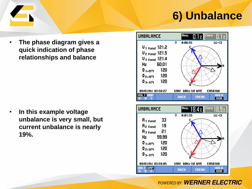
• The phase diagram gives a
quick indication of phase
relationships and balance
• In this example voltage
unbalance is very small, but
current unbalance is nearly
19%.
6) Unbalance
greater than 1 means that most people will perceive flicker in an incandescent
7) Flicker Measurements
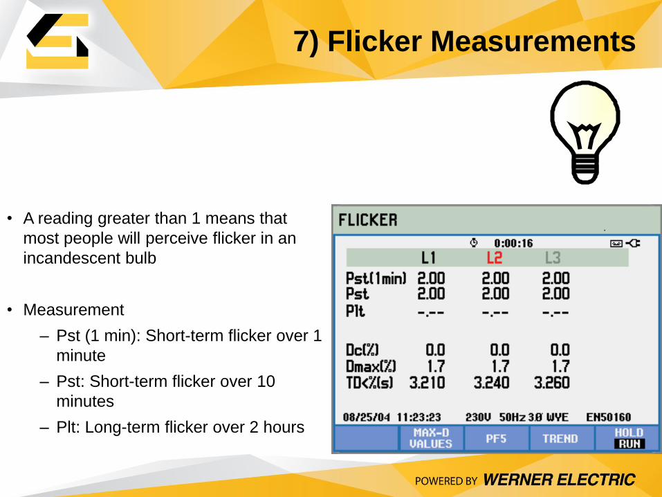
• A reading greater than 1 means that
most people will perceive flicker in an
incandescent bulb
• Measurement
– Pst (1 min): Short-term flicker over 1
minute
– Pst: Short-term flicker over 10
minutes
– Plt: Long-term flicker over 2 hours
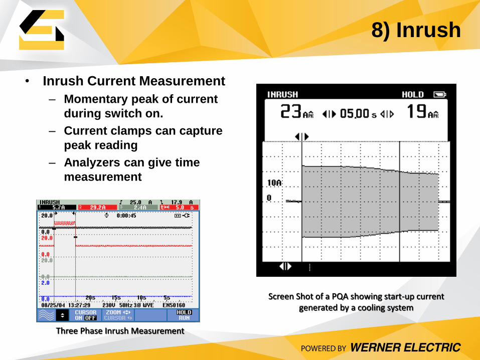
• Inrush Current Measurement
– Momentary peak of current
during switch on.
– Current clamps can capture
peak reading
– Analyzers can give time
measurement
Screen Shot of a PQA showing start-up current generated by a cooling system
Three Phase Inrush Measurement
8) Inrush
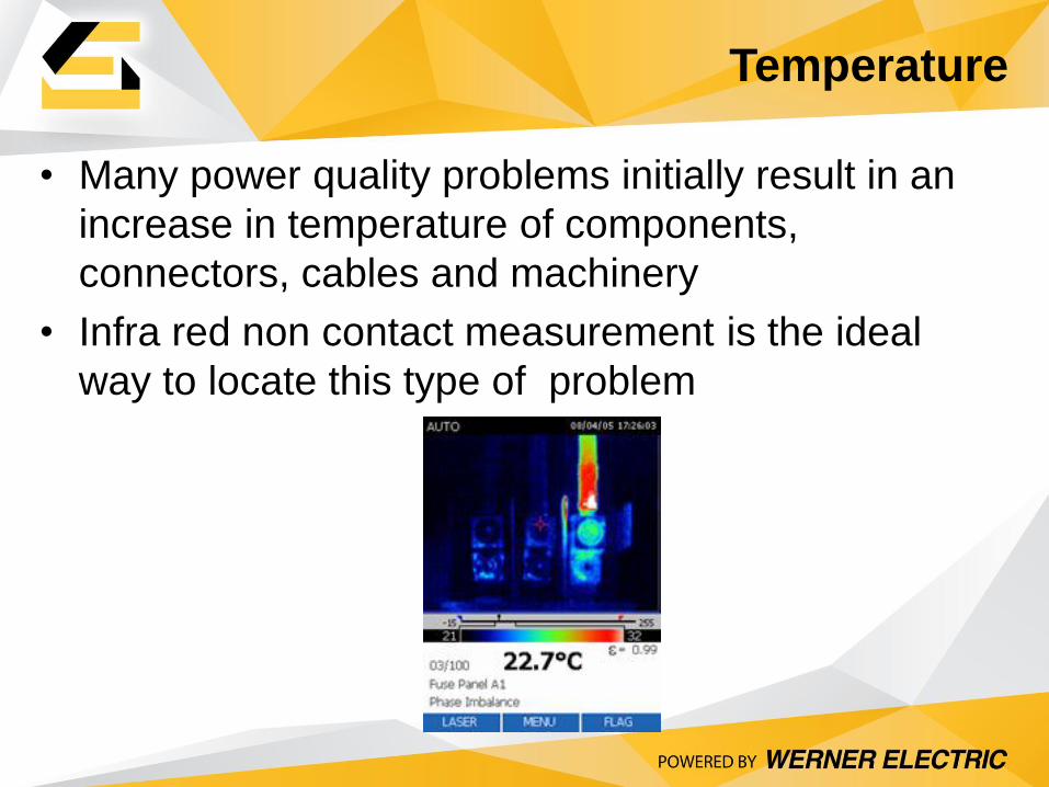
• Many power quality problems initially result in an
increase in temperature of components,
connectors, cables and machinery
• Infra red non contact measurement is the ideal
way to locate this type of problem
Temperature
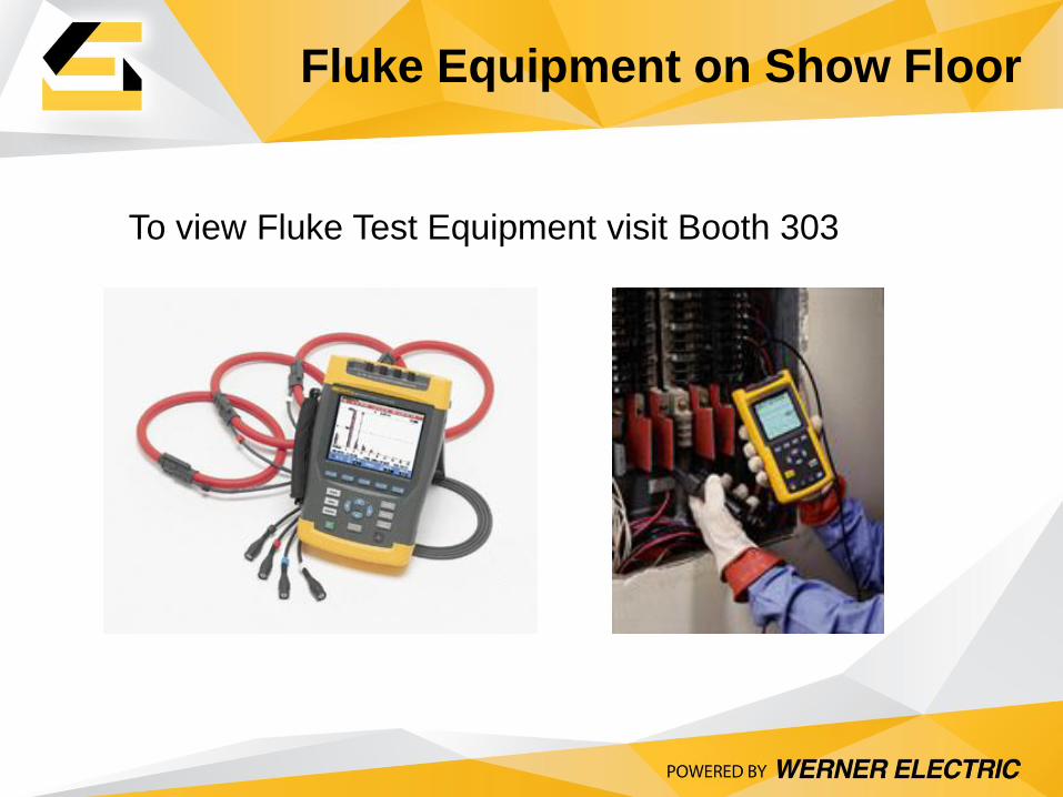
Fluke Equipment on Show Floor
To view Fluke Test Equipment visit Booth 303
Related Presentations:
PQ01 – Harmonic Solutions for VFD’s
PQ02 - Power Quality and Monitoring with iSense/iGrid/DySC & Surge/Sag/Transient Protection
Fluke Meters Booth 604
Rockwell Power Quality Solutions area SA1
46
Power Quality
Questions?
For questions or additional information please contact:
Mark Skoyen
Werner Electric
715-855-0584