Embed Size (px)
Citation preview
6/7/2015
1
Using Suggar++ With
Unstructured Grids
Ralph Noack, Ph.D.
President
Celeritas Simulation Technology, LLC
www.CeleritasSimTech.com
1
Outline
• Brief overview of overset approach
• Why use Overset?
• Introduction to Suggar++ Inputs
• Summary
2
6/7/2015
2
Overset / Chimera Fundamentals
• Set of body fitted grids (structured or unstructured) are constructed around each component of a complex configuration
• Component grids are constructed (mostly) independently from each other
• Overlap each other arbitrarily within each component, and between all components
• Interpolation links solution on component grids
6/7/2015
3
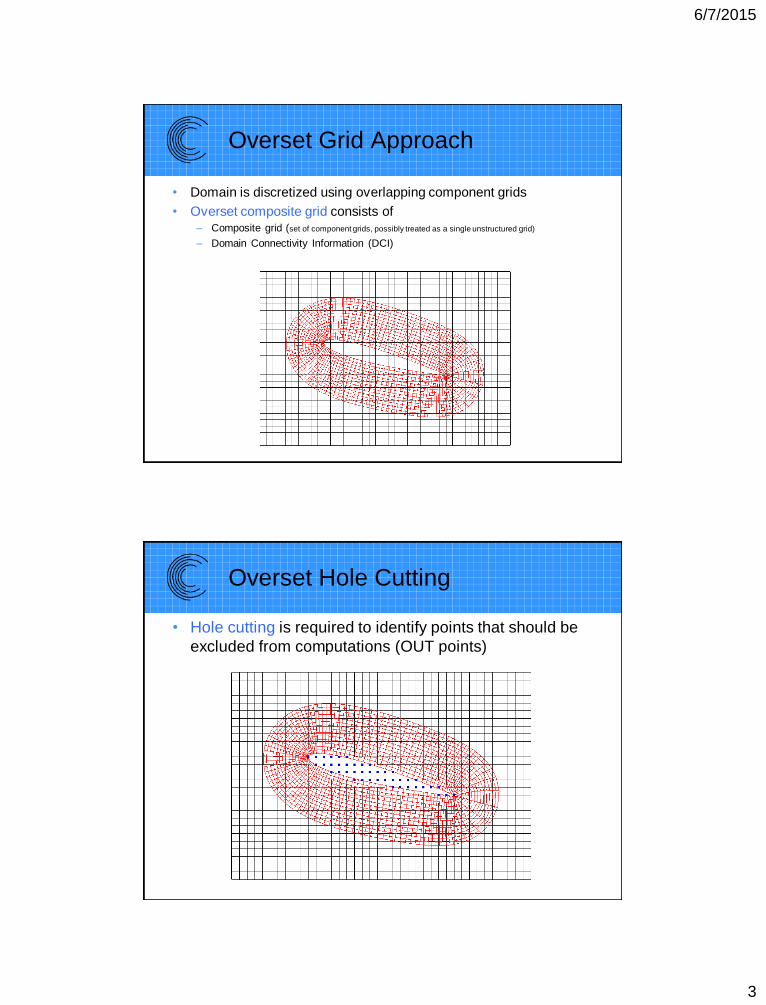
Overset Grid Approach
• Domain is discretized using overlapping component grids
• Overset composite grid consists of– Composite grid (set of component grids, possibly treated as a single unstructured grid)
– Domain Connectivity Information (DCI)
Overset Hole Cutting
• Hole cutting is required to identify points that should be
excluded from computations (OUT points)
6/7/2015
4
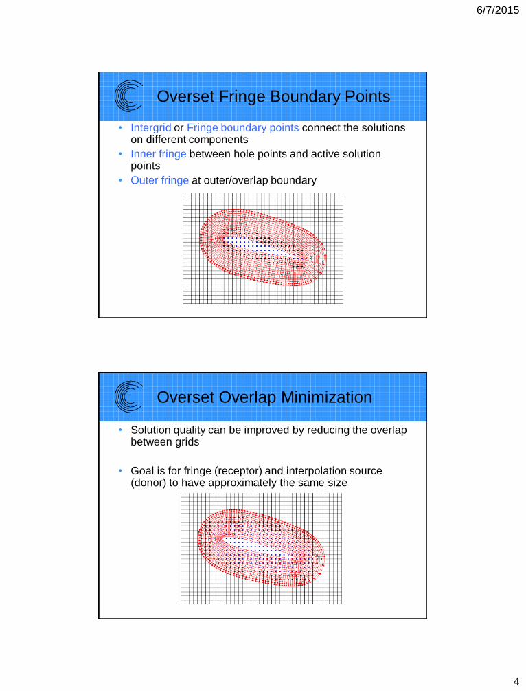
Overset Fringe Boundary Points
• Intergrid or Fringe boundary points connect the solutions on different components
• Inner fringe between hole points and active solution points
• Outer fringe at outer/overlap boundary
Overset Overlap Minimization
• Solution quality can be improved by reducing the overlap between grids
• Goal is for fringe (receptor) and interpolation source (donor) to have approximately the same size
6/7/2015
5
9
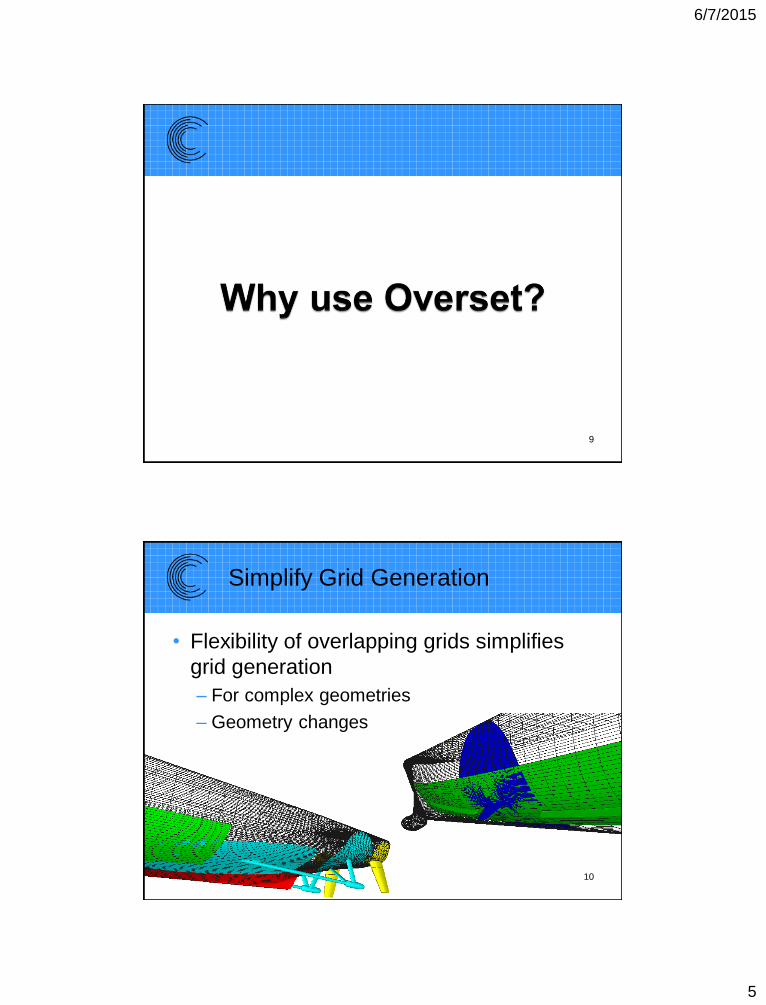
Simplify Grid Generation
• Flexibility of overlapping grids simplifies
grid generation
– For complex geometries
– Geometry changes
10
6/7/2015
6
Example of Flexibility
Easily Modify Geometry
11
Turbine Blade With Cooling Hole
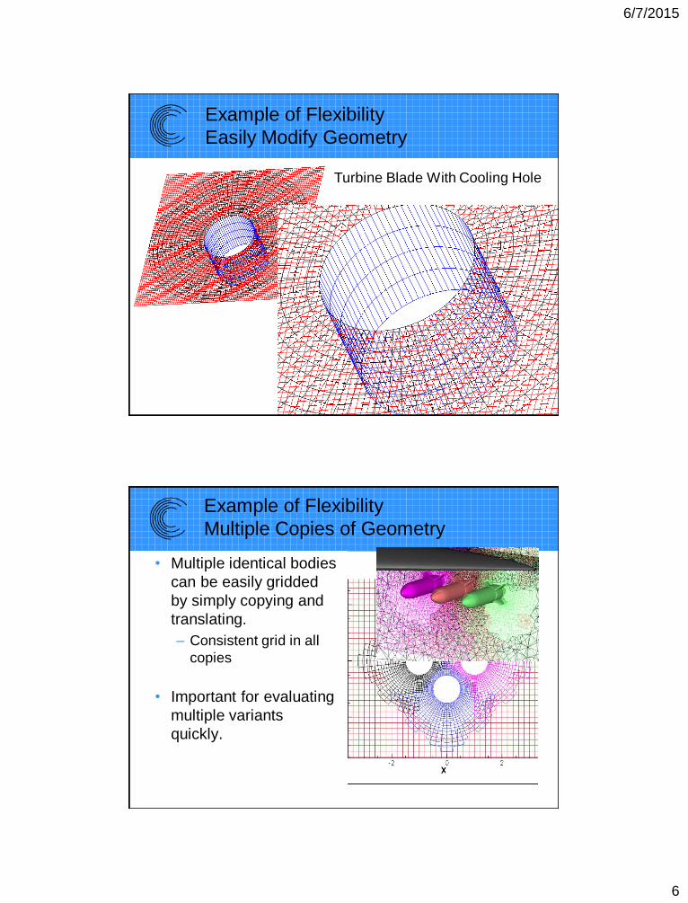
Example of Flexibility
Multiple Copies of Geometry
• Multiple identical bodies
can be easily gridded
by simply copying and
translating.
– Consistent grid in all
copies
• Important for evaluating
multiple variants
quickly.
6/7/2015
7
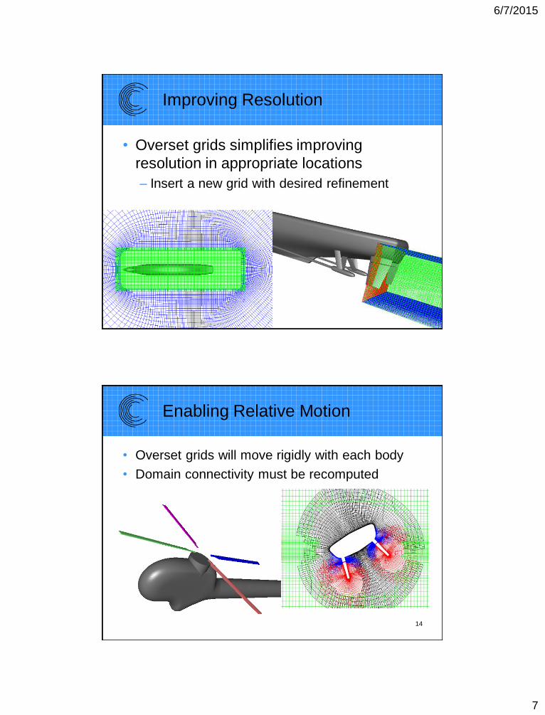
Improving Resolution
• Overset grids simplifies improving
resolution in appropriate locations
– Insert a new grid with desired refinement
13
Enabling Relative Motion
• Overset grids will move rigidly with each body
• Domain connectivity must be recomputed
14
6/7/2015
8
15
Overset Grid Generation
“Requirements”
• Need sufficient overlap between grids
• Better flow solution when
– Cell size is consistent in overlap region
• Fringe & donor have similar sizes
– Do not have large regions of overlap
• Use overlap minimization procedure to trim excess
overlap
16
6/7/2015
9
17
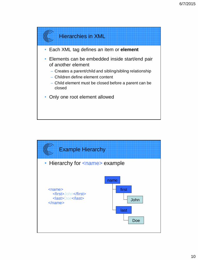
XML Tags/Markup Constructs
• An XML tag is enclosed in “< >”– <start>
• Must have an associated end tag– Same as start tag but with / after <
– </start>
<name>
<first>John</first>
<last>Doe</last>
</name>
• Empty elements can have implicit end tag
– <name></name> can be written as <name/>
6/7/2015
10
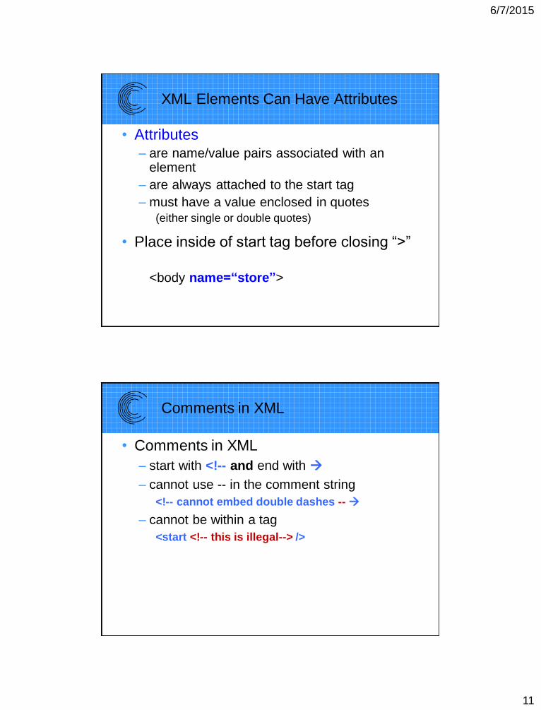
Hierarchies in XML
• Each XML tag defines an item or element
• Elements can be embedded inside start/end pair
of another element
– Creates a parent/child and sibling/sibling relationship
– Children define element content
– Child element must be closed before a parent can be
closed
• Only one root element allowed
Example Hierarchy
• Hierarchy for <name> example
name
first
last
John
Doe
<name><first>John</first><last>Doe</last>
</name>
6/7/2015
11
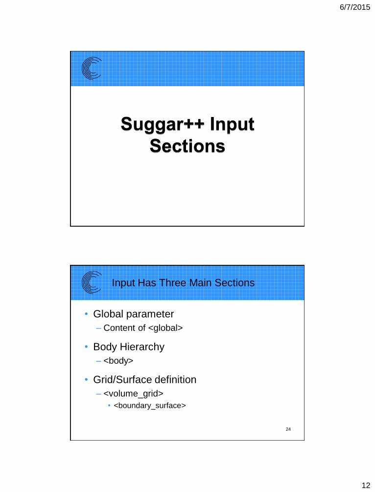
XML Elements Can Have Attributes
• Attributes
– are name/value pairs associated with an element
– are always attached to the start tag
– must have a value enclosed in quotes(either single or double quotes)
• Place inside of start tag before closing “>”
<body name=“store”>
Comments in XML
• Comments in XML
– start with <!-- and end with
– cannot use -- in the comment string
<!-- cannot embed double dashes --
– cannot be within a tag
<start <!-- this is illegal--> />
6/7/2015
12
Input Has Three Main Sections
• Global parameter
– Content of <global>
• Body Hierarchy
– <body>
• Grid/Surface definition
– <volume_grid>
• <boundary_surface>
24
6/7/2015
13
Values Specified by Attributes
• All input values are specified by element
attributes
– <body name=“root”>
– Data between elements (PCDATA) is ignored
• Can use as comments, some restricted characters
• Some attributes are required
– Will abort if not present
• Other attributes are optional25
6/7/2015
14
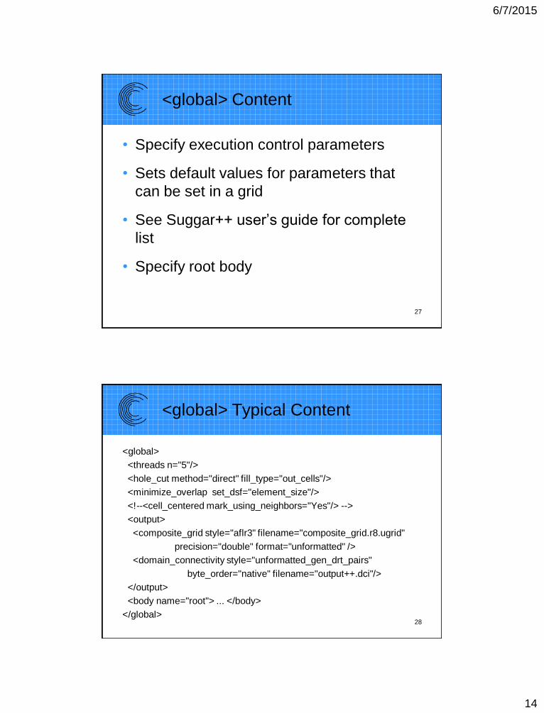
<global> Content
• Specify execution control parameters
• Sets default values for parameters that
can be set in a grid
• See Suggar++ user’s guide for complete
list
• Specify root body
27
<global> Typical Content
<global>
<threads n="5"/>
<hole_cut method="direct" fill_type="out_cells"/>
<minimize_overlap set_dsf="element_size"/>
<!--<cell_centered mark_using_neighbors="Yes"/> -->
<output>
<composite_grid style="aflr3" filename="composite_grid.r8.ugrid"
precision="double" format="unformatted" />
<domain_connectivity style="unformatted_gen_drt_pairs"
byte_order="native" filename="output++.dci"/>
</output>
<body name="root"> ... </body>
</global>28
6/7/2015
15
Composite Grid
• Best if flow solver uses composite grid
written by Suggar++
– Exporting from grid generator has possibility
of incorrect order of component grids
• Use <composite_grid/> to specify format
and filename
• Some restrictions on format of input
component grids and output composite
grid 29
6/7/2015
16
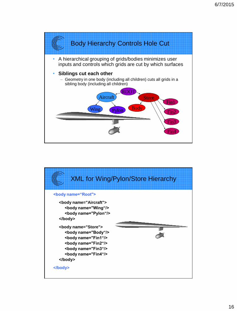
Body Hierarchy Controls Hole Cut
• A hierarchical grouping of grids/bodies minimizes user inputs and controls which grids are cut by which surfaces
• Siblings cut each other– Geometry in one body (including all children) cuts all grids in a
sibling body (including all children)
ROOTAircraft Store
Wing Pylon Body
Fin1
Fin2
Fin3
Fin4
XML for Wing/Pylon/Store Hierarchy
<body name=“Root">
<body name="Aircraft">
<body name="Wing“/>
<body name="Pylon“/>
</body>
<body name="Store">
<body name="Body“/>
<body name="Fin1“/>
<body name="Fin2“/>
<body name="Fin3“/>
<body name="Fin4“/>
</body>
</body>
6/7/2015
17
Transformations
• Associated with a body
• Hierarchical: Child body transforms are relative to parent
• Order dependent
• Suggar++ has two different types of transformations– Static transformations
• Applied to the grid coordinates on input
• Original coordinates are replaced by transformed coordinates
– Dynamic transformations
• Flags the body as moving
• Grid coordinates are left in original coordinates
– Transformations are always from original coordinate system
• Transformations are used internally during execution
• Output grids are transformed
6/7/2015
18
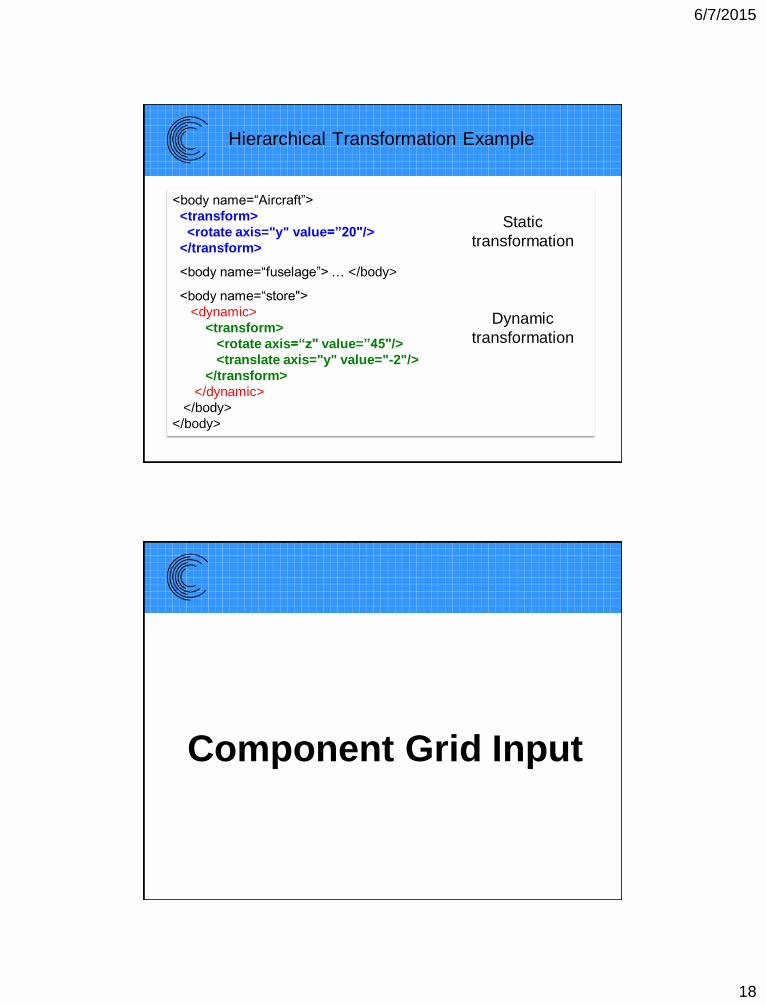
Hierarchical Transformation Example
<body name=“Aircraft”>
<transform>
<rotate axis="y" value=”20"/>
</transform>
<body name=“fuselage”> … </body>
<body name=“store">
<dynamic>
<transform>
<rotate axis=“z" value=”45"/>
<translate axis="y" value="-2"/>
</transform>
</dynamic>
</body>
</body>
Static
transformation
Dynamic
transformation
Component Grid Input
6/7/2015
19
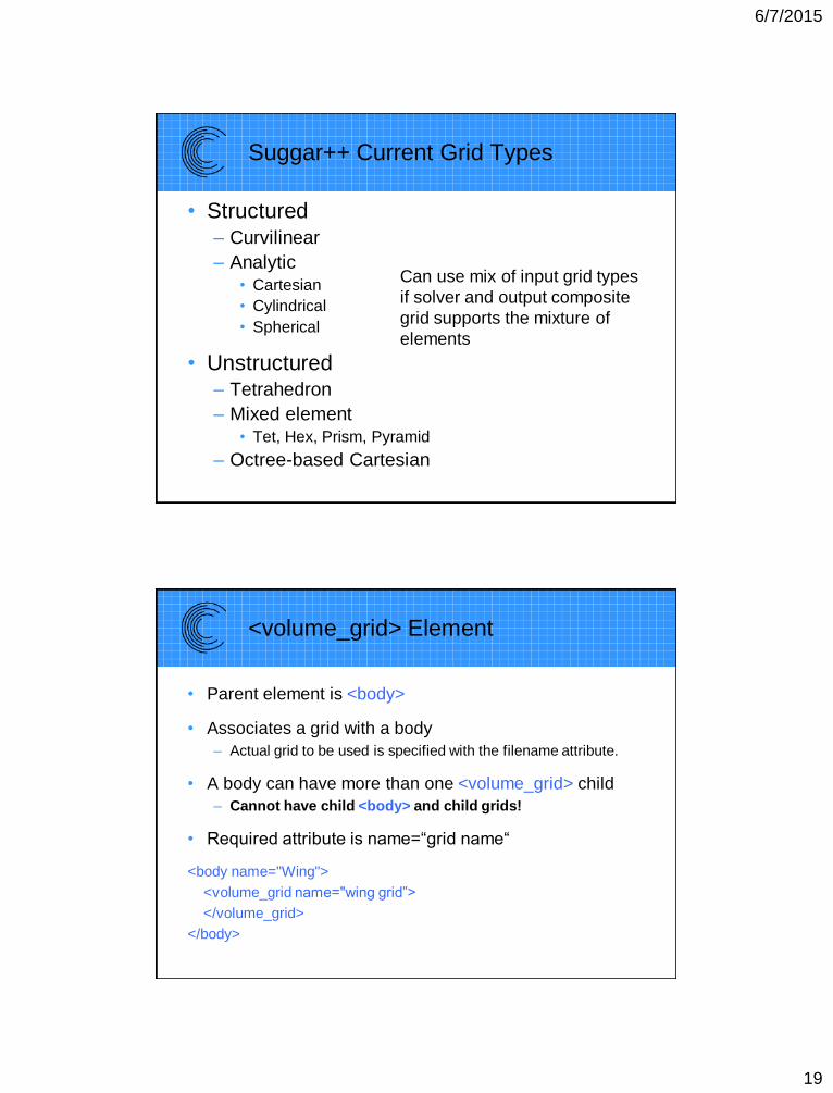
Suggar++ Current Grid Types
• Structured
– Curvilinear
– Analytic• Cartesian
• Cylindrical
• Spherical
• Unstructured– Tetrahedron
– Mixed element• Tet, Hex, Prism, Pyramid
– Octree-based Cartesian
Can use mix of input grid types
if solver and output composite
grid supports the mixture of
elements
<volume_grid> Element
• Parent element is <body>
• Associates a grid with a body
– Actual grid to be used is specified with the filename attribute.
• A body can have more than one <volume_grid> child
– Cannot have child <body> and child grids!
• Required attribute is name=“grid name“
<body name="Wing">
<volume_grid name="wing grid”>
</volume_grid>
</body>
6/7/2015
20
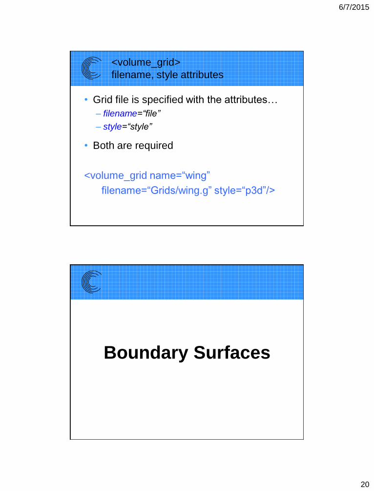
<volume_grid>
filename, style attributes
• Grid file is specified with the attributes…
– filename=“file”
– style=“style”
• Both are required
<volume_grid name=“wing”
filename=“Grids/wing.g” style=“p3d”/>
Boundary Surfaces
6/7/2015
21
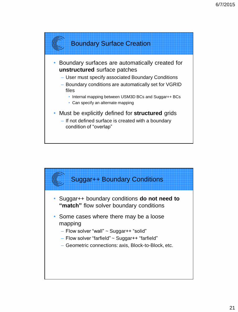
Boundary Surface Creation
• Boundary surfaces are automatically created for
unstructured surface patches
– User must specify associated Boundary Conditions
– Boundary conditions are automatically set for VGRID
files
• Internal mapping between USM3D BCs and Suggar++ BCs
• Can specify an alternate mapping
• Must be explicitly defined for structured grids
– If not defined surface is created with a boundary
condition of “overlap”
Suggar++ Boundary Conditions
• Suggar++ boundary conditions do not need to
“match” flow solver boundary conditions
• Some cases where there may be a loose
mapping
– Flow solver “wall” ~ Suggar++ “solid”
– Flow solver “farfield” ~ Suggar++ “farfield”
– Geometric connections: axis, Block-to-Block, etc.
6/7/2015
22
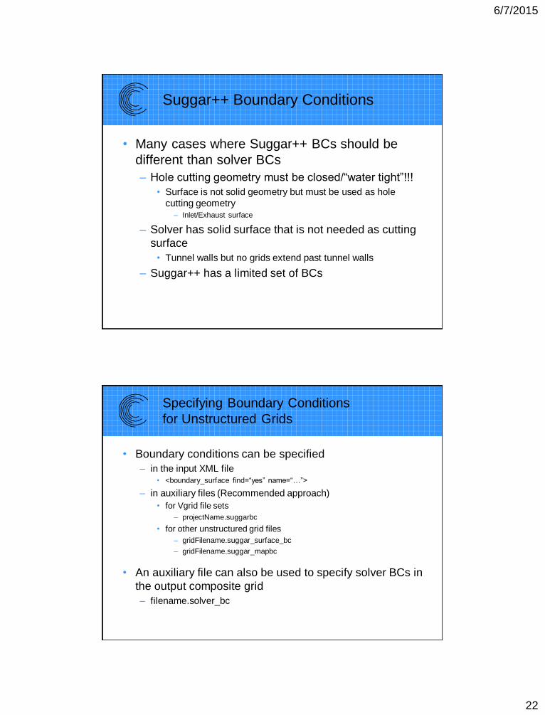
Suggar++ Boundary Conditions
• Many cases where Suggar++ BCs should be
different than solver BCs
– Hole cutting geometry must be closed/“water tight”!!!
• Surface is not solid geometry but must be used as hole
cutting geometry– Inlet/Exhaust surface
– Solver has solid surface that is not needed as cutting
surface
• Tunnel walls but no grids extend past tunnel walls
– Suggar++ has a limited set of BCs
Specifying Boundary Conditions
for Unstructured Grids
• Boundary conditions can be specified
– in the input XML file• <boundary_surface find=“yes” name=“…”>
– in auxiliary files (Recommended approach)
• for Vgrid file sets
– projectName.suggarbc
• for other unstructured grid files
– gridFilename.suggar_surface_bc
– gridFilename.suggar_mapbc
• An auxiliary file can also be used to specify solver BCs in
the output composite grid
– filename.solver_bc
6/7/2015
23
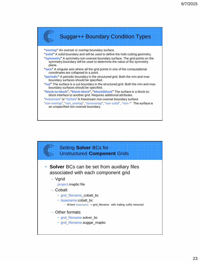
Suggar++ Boundary Condition Types
“overlap” An overset or overlap boundary surface.
“solid” A solid boundary and will be used to define the hole cutting geometry.
“symmetry” A symmetry non-overset boundary surface. The grid points on the symmetry boundary will be used to determine the value of the symmetry plane.
“axis” A singular axis where all the grid points in one of the computational coordinates are collapsed to a point.
“periodic” A periodic boundary in the structured grid. Both the min and max boundary surfaces should be specified.
“cut” The surface is a cut boundary in the structured grid. Both the min and max boundary surfaces should be specified.
“block-to-block”, “block-block”, “block2block” The surface is a block-to-block interface to another grid. Requires additional attributes.
“freestream” or “farfield” A freestream non-overset boundary surface
“non-overlap”, “non_overlap”, “nonoverlap”, “non-solid” , “non-*” The surface is an unspecified non-overset boundary.
Setting Solver BCs for
Unstructured Component Grids
• Solver BCs can be set from auxiliary files
associated with each component grid
– Vgrid
project.mapbc file
– Cobalt
• grid_filename_cobalt_bc
• basename.cobalt_bc– Where basename = grid_filename with trailing suffix removed
– Other formats
• grid_filename.solver_bc
• grid_filename.suggar_mapbc
6/7/2015
24
Solver BCs for
Unstructured Composite Grid
• Suggar++ will write selected solver
boundary condition files for the composite
grid
– Vgrid
project.mapbc file
– Cobalt
composite_grid_filename_cobalt_bc
– Other unstructured grid formats
composite_grid_filename.suggar_mapbc
Overlapping
Surface Grids
6/7/2015
25
Overlapping Surface Grids:
Additional Complexities
• Overlapping surfaces will have different
discrete representations
• Surfaces in a grid can be associated with
different geometry components
– Grid is in one body but some surfaces define
geometry in another body
• Overlapping surfaces require special
treatment to eliminate double counting in
Force and Moment integration
Overlapping Surface Grids:
Different Discrete Representations
• Surfaces that overlap on geometry with
curvature will have different discrete
representations
• Difficulties arise when the tangential
spacing is “large” relative to the curvature
and the normal spacing
• Special procedures are required to
properly find appropriate donors
6/7/2015
26
Surface Assembly
• Grid points are not changed
• Fringe points are shifted during the donor search
– Requires grid with structure normal to the surface
• Structured grid or mixed element with hex/prism layers
• Vgrid tet mesh with layers and poin1 file
• Surface assembly procedure is use to find the
shift for each fringe point
– Enabled with <surface_assembly/> element
– Relative to overlapping surface in each donor grid
• A fringe point will have different shifts/offsets for each donor
grid
52
6/7/2015
27
Integrating Force And Moments
On Overlapping Surfaces
• Special treatment to eliminate double counting in
force and moment integration
– Panel weights
• Weight factor between 0 & 1 for each integration surface
face/panel
– Single valued/water tight integration surface
• Remove overlap, glue remaining portions of original surfaces
together using new triangles
Suggar++ has integrated USURP capability
• Enabled with <usurp> element
• Output
– Panel weights
• Included in DCI file: Can be retrieved via DiRTlib
• Written to files
– Can create zipper grid
• Water tight surface grid with overlap eliminated
• Not sufficiently robust
6/7/2015
28
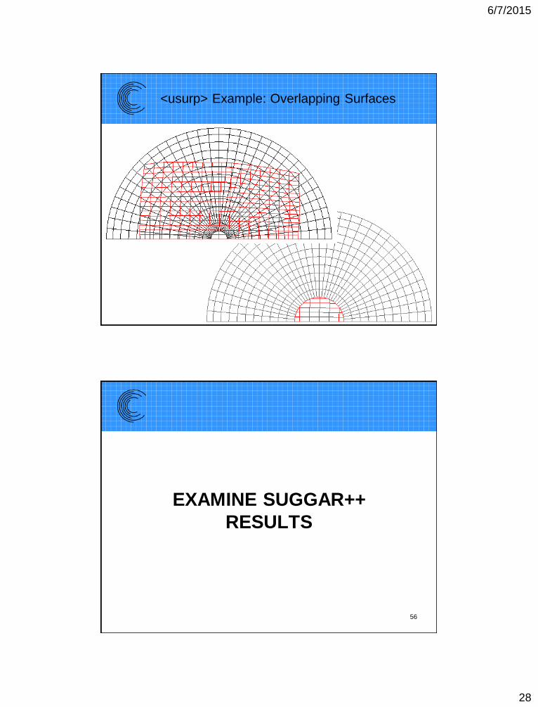
<usurp> Example: Overlapping Surfaces
EXAMINE SUGGAR++
RESULTS
56
6/7/2015
29
General Suggestions
Check Suggar++ Output
• Look at
– summary.log
– Standard error output file
• Suggar++ -reopen will write to out.stderr++
• Visualize the DCI
– Look at orphans
– All blanked points
• May have flood fill leak if entire grid is blanked out
– Use gviz or pointwise
SUGGAR++ USER’S GUIDE
58
6/7/2015
30
Suggar++ User’s Guide
• List of all inputs elements
– Hyperlinked to parent element
– Possible child content
• List of attributes
– Hyperlinked to parent element
• Sections on usage, advance topics, grid
formats, etc.
59
SUMMARY
60
6/7/2015
31
Summary
• Overset grids are an enabling technology
– Simplifies grid generation/model changes
– Enables moving body simulations
• Briefly presented some Suggar++ Inputs
• Briefly discussed overlapping surface grids
– Need surface assembly if overlapping
surfaces are not planar
– Force & Moment integration needs procedure
to eliminate double counting 61
62
Commercial distribution and support
for Suggar++ provided by
Celeritas Simulation Technology, LLC
http://www.CeleritasSimTech.com
Exportable under an EAR-99 license