Embed Size (px)
Citation preview
PREVIEW
COPY
Table of Contents
Lesson One Turbines............................................................................................3
Lesson Two Boiler Instrumentation, Controls, and Safety.................................21
Lesson Three Electrical Power Fundamentals......................................................37
Lesson Four Electrical Systems Analysis...........................................................53
Lesson Five Air-Conditioning Systems..............................................................69
© Copyright 1975, 1995, 2001 by TPC Training Systems, a division of Telemedia, Inc.
All rights reserved, including those of translation.
Printed and videotaped courseware are subject to the copyright laws of the United States. You are not autho-rized to make any copies of this material. If you do, then you are subject to the penalties provided under thecopyright law, which include statutory damages up to $50,000 for each infringement of copyrighted material, andalso recovery of reasonable attorneys’ fees. Further, you could be subject to criminal prosecution pursuant to 18U.S.C. § 2319.
Using Steam in thePower Plant
USING STEAM IN THE POWER PLANT
Lesson One
Turbines
11301
PREVIEW
COPY
PREVIEW
COPY
1
4
Lesson
Turbines
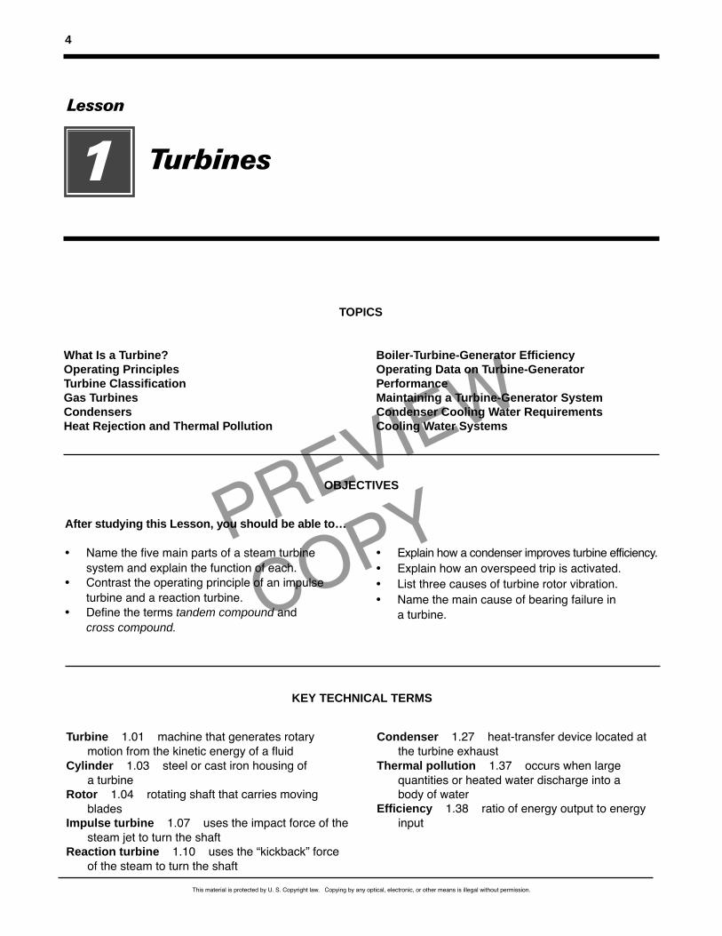
What Is a Turbine?Operating PrinciplesTurbine ClassificationGas TurbinesCondensersHeat Rejection and Thermal Pollution
Boiler-Turbine-Generator EfficiencyOperating Data on Turbine-Generator PerformanceMaintaining a Turbine-Generator SystemCondenser Cooling Water RequirementsCooling Water Systems
TOPICS
After studying this Lesson, you should be able to…
• Name the five main parts of a steam turbinesystem and explain the function of each.
• Contrast the operating principle of an impulseturbine and a reaction turbine.
• Define the terms tandem compound andcross compound.
• Explain how a condenser improves turbine efficiency.• Explain how an overspeed trip is activated.• List three causes of turbine rotor vibration.• Name the main cause of bearing failure in
a turbine.
OBJECTIVES
Turbine 1.01 machine that generates rotarymotion from the kinetic energy of a fluid
Cylinder 1.03 steel or cast iron housing ofa turbine
Rotor 1.04 rotating shaft that carries movingblades
Impulse turbine 1.07 uses the impact force of thesteam jet to turn the shaft
Reaction turbine 1.10 uses the “kickback” forceof the steam to turn the shaft
Condenser 1.27 heat-transfer device located atthe turbine exhaust
Thermal pollution 1.37 occurs when large quantities or heated water discharge into a body of water
Efficiency 1.38 ratio of energy output to energyinput
KEY TECHNICAL TERMS
This material is protected by U. S. Copyright law. Copying by any optical, electronic, or other means is illegal without permission.
PREVIEW
COPY
What Is a Turbine?
1.01 A turbine is a machine that generatesmechanical power in the form of rotary motion fromthe kinetic energy of a fluid (steam, air, or water). The most powerful and widely used turbines aresteam turbines. Steam turbines drive many kinds ofpower plant equipment. This equipment includes electric generators, pumps, and compressors. The output capacity of a steam turbine ranges from lessthan 1 kW to more than one million kW. The largercapacity steam turbines drive the electric generatorsin power plants.
1.02 A steam turbine consists of the following parts:
• a cylinder (casing or shell) containing thefixed (stationary) blade system and a set ofbearings to support the rotor shaft
• a rotor carrying the moving blades (bucketsor vanes) with bearing journals on the ends ofits shaft
• a governor and valve system to regulate theturbine's speed and power by controlling thesteam flow, and an oil system for lubricatingthe bearings and for hydraulically operatingthe control valves by means of a relay systemconnected with the governor
• a coupling or gear reducer to connect with themachine driven
• pipe connections to the steam supply from theboiler at the inlet, and to an exhaust system atthe outlet, of the casing.
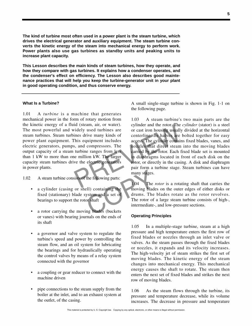
A small single-stage turbine is shown in Fig. 1-1 onthe following page.
1.03 A steam turbine's two main parts are thecylinder and the rotor. The cylinder (stator) is a steelor cast iron housing usually divided at the horizontalcenterline. Its halves are bolted together for easyaccess. The cylinder contains fixed blades, vanes, andnozzles that direct steam into the moving blades carried by the rotor. Each fixed blade set is mountedin diaphragms located in front of each disk on therotor, or directly in the casing. A disk and diaphragmpair form a turbine stage. Steam turbines can havemany stages.
1.04 The rotor is a rotating shaft that carries themoving blades on the outer edges of either disks ordrums. The blades rotate as the rotor revolves. The rotor of a large steam turbine consists of high-,intermediate-, and low-pressure sections.
Operating Principles
1.05 In a multiple-stage turbine, steam at a highpressure and high temperature enters the first row offixed blades or nozzles through an inlet valve orvalves. As the steam passes through the fixed bladesor nozzles, it expands and its velocity increases. The high-velocity jet of steam strikes the first set ofmoving blades. The kinetic energy of the steamchanges into mechanical energy. This mechanicalenergy causes the shaft to rotate. The steam thenenters the next set of fixed blades and strikes the nextrow of moving blades.
1.06 As the steam flows through the turbine, itspressure and temperature decrease, while its volumeincreases. The decrease in pressure and temperature
5
The kind of turbine most often used in a power plant is the steam turbine, whichdrives the electrical generator and auxiliary equipment. The steam turbine con-verts the kinetic energy of the steam into mechanical energy to perform work.Power plants also use gas turbines as standby units and peaking units toincrease plant capacity.
This Lesson describes the main kinds of steam turbines, how they operate, andhow they compare with gas turbines. It explains how a condenser operates, andthe condenser's effect on efficiency. The Lesson also describes good mainte-nance practices that will help you keep the turbine-generator unit in your plantin good operating condition, and thus conserve energy.
This material is protected by U. S. Copyright law. Copying by any optical, electronic, or other means is illegal without permission.
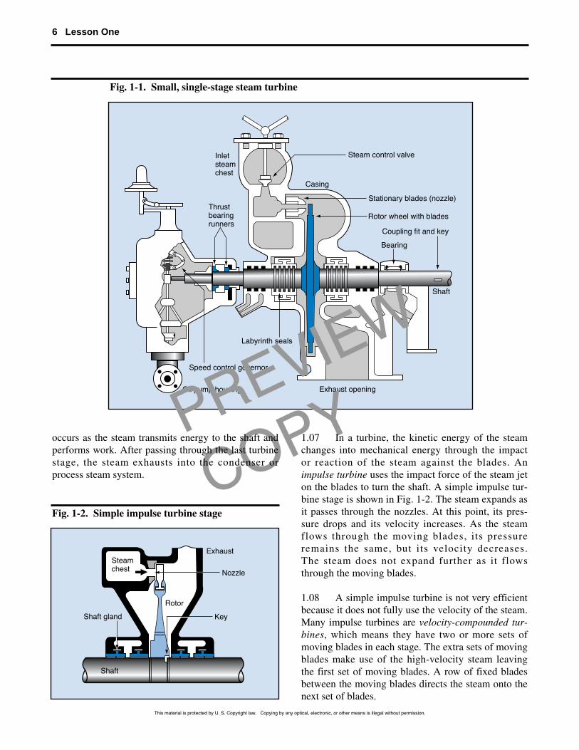
Speed control governor
Inletsteamchest
Steam control valve
Stationary blades (nozzle)
Rotor wheel with blades
Casing
Shaft
Bearing
Coupling fit and key
Exhaust opening
Labyrinth seals
Thrustbearingrunners
Oil pump housing
PREVIEW
COPYoccurs as the steam transmits energy to the shaft andperforms work. After passing through the last turbinestage, the steam exhausts into the condenser or process steam system.
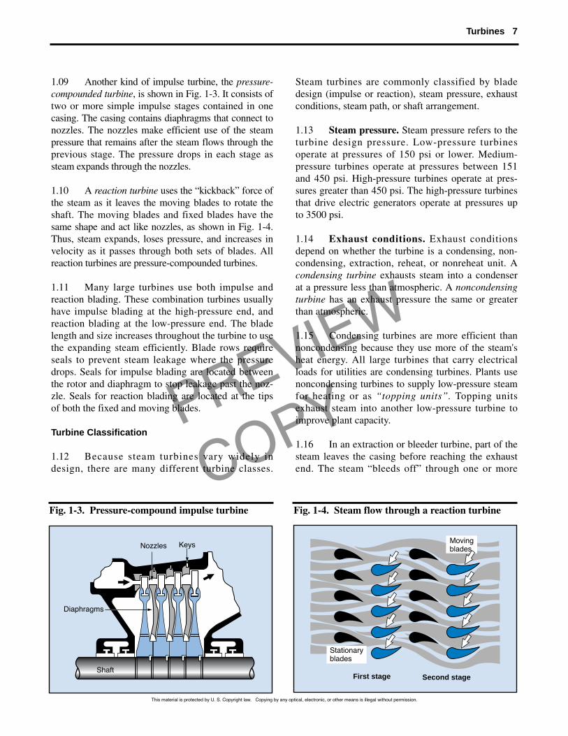
1.07 In a turbine, the kinetic energy of the steamchanges into mechanical energy through the impactor reaction of the steam against the blades. Animpulse turbine uses the impact force of the steam jeton the blades to turn the shaft. A simple impulse tur-bine stage is shown in Fig. 1-2. The steam expands asit passes through the nozzles. At this point, its pres-sure drops and its velocity increases. As the steamflows through the moving blades, its pressureremains the same, but its velocity decreases. The steam does not expand further as it flowsthrough the moving blades.
1.08 A simple impulse turbine is not very efficientbecause it does not fully use the velocity of the steam.Many impulse turbines are velocity-compounded tur-bines, which means they have two or more sets ofmoving blades in each stage. The extra sets of movingblades make use of the high-velocity steam leavingthe first set of moving blades. A row of fixed bladesbetween the moving blades directs the steam onto thenext set of blades.
6 Lesson One
Fig. 1-1. Small, single-stage steam turbine
Shaft gland
Nozzle
Key
Exhaust
Rotor
Shaft
Steamchest
Fig. 1-2. Simple impulse turbine stage
This material is protected by U. S. Copyright law. Copying by any optical, electronic, or other means is illegal without permission.
PREVIEW
COPY
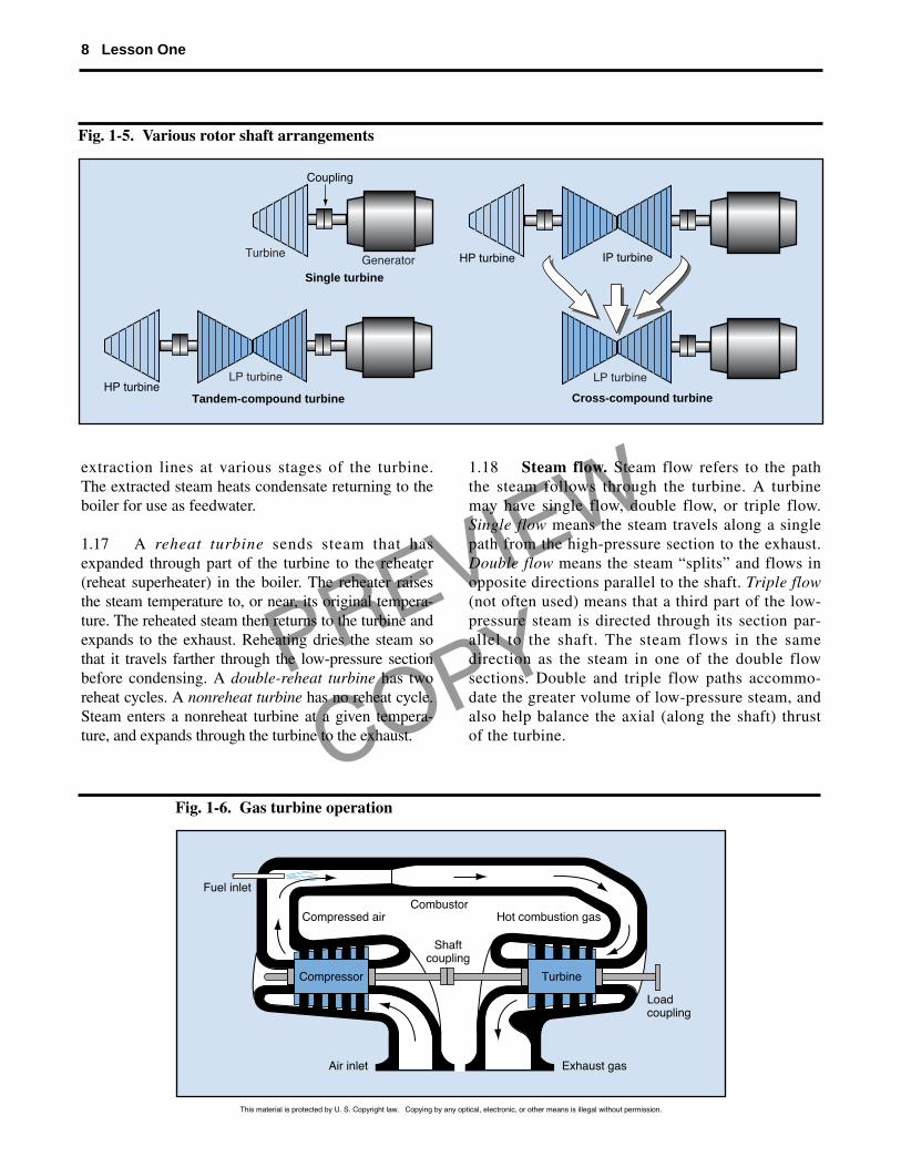
1.09 Another kind of impulse turbine, the pressure-compounded turbine, is shown in Fig. 1-3. It consists oftwo or more simple impulse stages contained in onecasing. The casing contains diaphragms that connect tonozzles. The nozzles make efficient use of the steampressure that remains after the steam flows through theprevious stage. The pressure drops in each stage assteam expands through the nozzles.
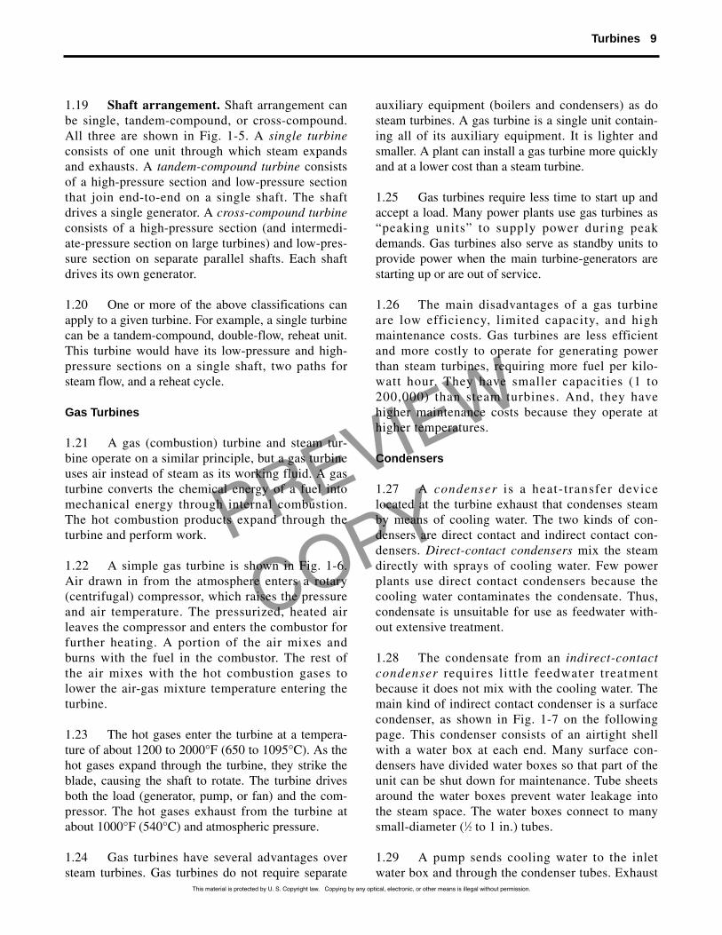
1.10 A reaction turbine uses the “kickback” force ofthe steam as it leaves the moving blades to rotate theshaft. The moving blades and fixed blades have thesame shape and act like nozzles, as shown in Fig. 1-4.Thus, steam expands, loses pressure, and increases invelocity as it passes through both sets of blades. Allreaction turbines are pressure-compounded turbines.
1.11 Many large turbines use both impulse andreaction blading. These combination turbines usuallyhave impulse blading at the high-pressure end, andreaction blading at the low-pressure end. The bladelength and size increases throughout the turbine to usethe expanding steam efficiently. Blade rows requireseals to prevent steam leakage where the pressuredrops. Seals for impulse blading are located betweenthe rotor and diaphragm to stop leakage past the noz-zle. Seals for reaction blading are located at the tipsof both the fixed and moving blades.
Turbine Classification
1.12 Because steam turbines vary widely indesign, there are many different turbine classes.
Steam turbines are commonly classified by bladedesign (impulse or reaction), steam pressure, exhaustconditions, steam path, or shaft arrangement.
1.13 Steam pressure. Steam pressure refers to theturbine design pressure. Low-pressure turbines operate at pressures of 150 psi or lower. Medium-pressure turbines operate at pressures between 151and 450 psi. High-pressure turbines operate at pres-sures greater than 450 psi. The high-pressure turbinesthat drive electric generators operate at pressures upto 3500 psi.
1.14 Exhaust conditions. Exhaust conditionsdepend on whether the turbine is a condensing, non-condensing, extraction, reheat, or nonreheat unit. Acondensing turbine exhausts steam into a condenserat a pressure less than atmospheric. A noncondensingturbine has an exhaust pressure the same or greaterthan atmospheric.
1.15 Condensing turbines are more efficient thannoncondensing because they use more of the steam'sheat energy. All large turbines that carry electricalloads for utilities are condensing turbines. Plants usenoncondensing turbines to supply low-pressure steamfor heating or as “topping units”. Topping unitsexhaust steam into another low-pressure turbine toimprove plant capacity.
1.16 In an extraction or bleeder turbine, part of thesteam leaves the casing before reaching the exhaustend. The steam “bleeds off” through one or more
Turbines 7
Diaphragms
Nozzles Keys
Shaft
Fig. 1-3. Pressure-compound impulse turbine
Stationaryblades
Movingblades
First stage Second stage
Fig. 1-4. Steam flow through a reaction turbine
This material is protected by U. S. Copyright law. Copying by any optical, electronic, or other means is illegal without permission.
PREVIEW
COPY
Fuel inletCombustor
Compressed air
Shaftcoupling
Compressor Turbine
Hot combustion gas
Loadcoupling
Exhaust gasAir inlet
extraction lines at various stages of the turbine. The extracted steam heats condensate returning to theboiler for use as feedwater.
1.17 A reheat turbine sends steam that hasexpanded through part of the turbine to the reheater(reheat superheater) in the boiler. The reheater raisesthe steam temperature to, or near, its original tempera-ture. The reheated steam then returns to the turbine andexpands to the exhaust. Reheating dries the steam sothat it travels farther through the low-pressure sectionbefore condensing. A double-reheat turbine has tworeheat cycles. A nonreheat turbine has no reheat cycle.Steam enters a nonreheat turbine at a given tempera-ture, and expands through the turbine to the exhaust.
1.18 Steam flow. Steam flow refers to the paththe steam follows through the turbine. A turbinemay have single flow, double flow, or triple flow.Single flow means the steam travels along a singlepath from the high-pressure section to the exhaust.Double flow means the steam “splits” and flows inopposite directions parallel to the shaft. Triple flow(not often used) means that a third part of the low-pressure steam is directed through its section par-allel to the shaft. The steam flows in the samedirection as the steam in one of the double flowsections. Double and triple flow paths accommo-date the greater volume of low-pressure steam, andalso help balance the axial (along the shaft) thrustof the turbine.
8 Lesson One
Cross-compound turbineTandem-compound turbine
Single turbine
HP turbine IP turbine
Coupling
LP turbine
TurbineGenerator
HP turbineLP turbine
Fig. 1-5. Various rotor shaft arrangements
Fig. 1-6. Gas turbine operation
This material is protected by U. S. Copyright law. Copying by any optical, electronic, or other means is illegal without permission.
PREVIEW
COPY
1.19 Shaft arrangement. Shaft arrangement canbe single, tandem-compound, or cross-compound.All three are shown in Fig. 1-5. A single turbineconsists of one unit through which steam expandsand exhausts. A tandem-compound turbine consistsof a high-pressure section and low-pressure sectionthat join end-to-end on a single shaft. The shaftdrives a single generator. A cross-compound turbineconsists of a high-pressure section (and intermedi-ate-pressure section on large turbines) and low-pres-sure section on separate parallel shafts. Each shaftdrives its own generator.
1.20 One or more of the above classifications canapply to a given turbine. For example, a single turbinecan be a tandem-compound, double-flow, reheat unit.This turbine would have its low-pressure and high-pressure sections on a single shaft, two paths forsteam flow, and a reheat cycle.
Gas Turbines
1.21 A gas (combustion) turbine and steam tur-bine operate on a similar principle, but a gas turbineuses air instead of steam as its working fluid. A gasturbine converts the chemical energy of a fuel intomechanical energy through internal combustion.The hot combustion products expand through theturbine and perform work.
1.22 A simple gas turbine is shown in Fig. 1-6.Air drawn in from the atmosphere enters a rotary(centrifugal) compressor, which raises the pressureand air temperature. The pressurized, heated airleaves the compressor and enters the combustor forfurther heating. A portion of the air mixes andburns with the fuel in the combustor. The rest ofthe air mixes with the hot combustion gases tolower the air-gas mixture temperature entering theturbine.
1.23 The hot gases enter the turbine at a tempera-ture of about 1200 to 2000°F (650 to 1095°C). As thehot gases expand through the turbine, they strike theblade, causing the shaft to rotate. The turbine drivesboth the load (generator, pump, or fan) and the com-pressor. The hot gases exhaust from the turbine atabout 1000°F (540°C) and atmospheric pressure.
1.24 Gas turbines have several advantages oversteam turbines. Gas turbines do not require separate
auxiliary equipment (boilers and condensers) as dosteam turbines. A gas turbine is a single unit contain-ing all of its auxiliary equipment. It is lighter andsmaller. A plant can install a gas turbine more quicklyand at a lower cost than a steam turbine.
1.25 Gas turbines require less time to start up andaccept a load. Many power plants use gas turbines as“peaking units” to supply power during peakdemands. Gas turbines also serve as standby units toprovide power when the main turbine-generators arestarting up or are out of service.
1.26 The main disadvantages of a gas turbineare low efficiency, limited capacity, and highmaintenance costs. Gas turbines are less efficientand more costly to operate for generating powerthan steam turbines, requiring more fuel per kilo-watt hour. They have smaller capacities (1 to200,000) than steam turbines. And, they havehigher maintenance costs because they operate athigher temperatures.
Condensers
1.27 A condenser is a heat-transfer devicelocated at the turbine exhaust that condenses steamby means of cooling water. The two kinds of con-densers are direct contact and indirect contact con-densers. Direct-contact condensers mix the steamdirectly with sprays of cooling water. Few powerplants use direct contact condensers because thecooling water contaminates the condensate. Thus,condensate is unsuitable for use as feedwater with-out extensive treatment.
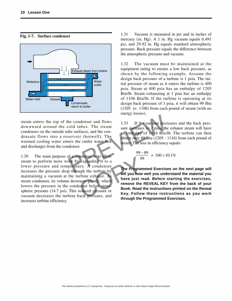
1.28 The condensate from an indirect-contactcondenser requires little feedwater treatmentbecause it does not mix with the cooling water. Themain kind of indirect contact condenser is a surfacecondenser, as shown in Fig. 1-7 on the followingpage. This condenser consists of an airtight shellwith a water box at each end. Many surface con-densers have divided water boxes so that part of theunit can be shut down for maintenance. Tube sheetsaround the water boxes prevent water leakage intothe steam space. The water boxes connect to manysmall-diameter (1⁄2 to 1 in.) tubes.
1.29 A pump sends cooling water to the inletwater box and through the condenser tubes. Exhaust
Turbines 9
This material is protected by U. S. Copyright law. Copying by any optical, electronic, or other means is illegal without permission.
PREVIEW
COPY
steam enters the top of the condenser and flowsdownward around the cold tubes. The steam condenses on the outside tube surfaces, and the con-densate flows into a reservoir (hotwell). Thewarmed cooling water enters the outlet water boxand discharges from the condenser.
1.30 The main purpose of a condenser is to allowsteam to perform more work by expanding it to alower pressure and temperature. A condenserincreases the pressure drop through the turbine bymaintaining a vacuum at the turbine exhaust. Assteam condenses, its volume decreases greatly, whichlowers the pressure in the condenser below atmo-spheric pressure (14.7 psi). This reduced pressure orvacuum decreases the turbine back pressure, andincreases turbine efficiency.
1.31 Vacuum is measured in psi and in inches ofmercury (in. Hg). A 1 in. Hg vacuum equals 0.491psi, and 29.92 in. Hg equals standard atmosphericpressure. Back pressure equals the difference betweenthe atmospheric pressure and vacuum.
1.32 The vacuum must be maintained at theequipment rating to ensure a low back pressure, asshown by the following example. Assume thedesign back pressure of a turbine is 1 psia. The ini-tial pressure of steam as it enters the turbine is 400psia. Steam at 400 psia has an enthalpy of 1205Btu/lb. Steam exhausting at 1 psia has an enthalpyof 1106 Btu/lb. If the turbine is operating at itsdesign back pressure of 1 psia, it will obtain 99 Btu(1205 to 1106) from each pound of steam (with noenergy losses).
1.33 If the vacuum decreases and the back pres-sure increases to 2 psia, the exhaust steam will havean enthalpy of 1116 Btu/lb. The turbine can thenobtain only 89 Btu (1205 - 1116) from each pound ofsteam. The loss in efficiency equals:
The Programmed Exercises on the next page willtell you how well you understand the material youhave just read. Before starting the exercises,remove the REVEAL KEY from the back of yourBook. Read the instructions printed on the RevealKey. Follow these instructions as you workthrough the Programmed Exercises.
99 8999
100 10 1− × = . %
10 Lesson One
Exhaust steam from turbine
Water outlet
Waterbox
Water inlet HotwellCondensatereturn to boiler
Fig. 1-7. Surface condenser
This material is protected by U. S. Copyright law. Copying by any optical, electronic, or other means is illegal without permission.
PREVIEW
COPY
1-1. A turbine rotor consists of a shaft withblades mounted on it.
1-2. Steam expands in an impulse turbinewhen it flows through the .
1-3. The kind of turbine that uses the kick-back force of steam is the
turbine.
1-4. The exhaust pressure of a condensingturbine is than atmospheric pressure.
1-5. A turbine that has both its high-pressureand low-pressure sections mounted on a single shaft is a(n) ______________ turbine.
1-6. A gas turbine performs work by meansof hot gases.
1-7. A surface condenser is a(n) -contact condenser.
1-8. How does a condenser allow steam toperform more work?
1-1. MOVING or ROTATINGEach blade set connects to a drumor disk.Ref: 1.04
1-2. NOZZLES
Ref: 1.07
1-3. REACTION
Ref: 1.10
1-4. LESS or LOWER
Ref: 1.14
1-5. TANDEM-COMPOUND
Ref: 1.19
1-6. COMBUSTIONThe gases expand through the turbine.
Ref: 1.21
1-7. INDIRECT
Ref: 1.28, Fig. 1-7
1-8. BY MAINTAINING A VACUUM AT THE TURBINE EXHAUST
Ref: 1.30
Programmed Exercises 11
This material is protected by U. S. Copyright law. Copying by any optical, electronic, or other means is illegal without permission.
PREVIEW
COPY
Heat Rejection and Thermal Pollution
1.34 The largest single loss of energy in a powerplant is the heat rejected to the condenser. More thanhalf of the heat energy of the steam leaving the boileris rejected or discarded to the condenser coolingwater. The heat lost is low-level heat, which means itstemperature is too low for practical heat recovery.
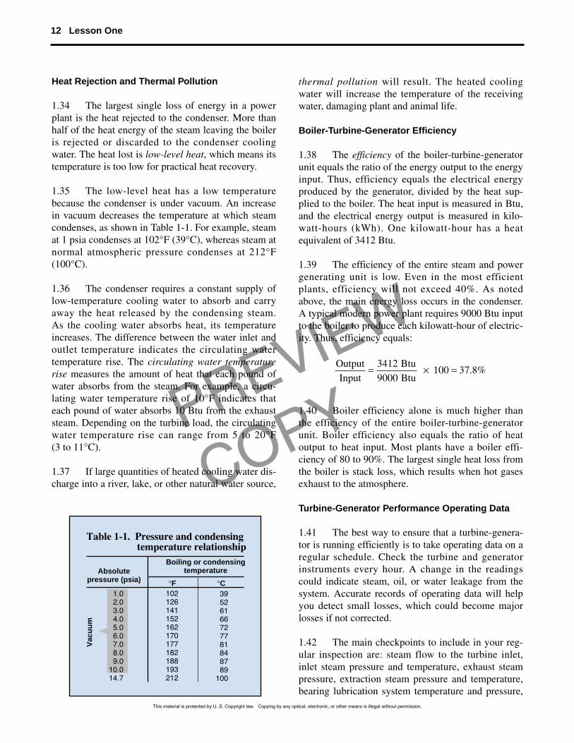
1.35 The low-level heat has a low temperaturebecause the condenser is under vacuum. An increasein vacuum decreases the temperature at which steamcondenses, as shown in Table 1-1. For example, steamat 1 psia condenses at 102°F (39°C), whereas steam atnormal atmospheric pressure condenses at 212°F(100°C).
1.36 The condenser requires a constant supply oflow-temperature cooling water to absorb and carryaway the heat released by the condensing steam. As the cooling water absorbs heat, its temperatureincreases. The difference between the water inlet andoutlet temperature indicates the circulating water temperature rise. The circulating water temperaturerise measures the amount of heat that each pound ofwater absorbs from the steam. For example, a circu-lating water temperature rise of 10°F indicates thateach pound of water absorbs 10 Btu from the exhauststeam. Depending on the turbine load, the circulatingwater temperature rise can range from 5 to 20°F (3 to 11°C).
1.37 If large quantities of heated cooling water dis-charge into a river, lake, or other natural water source,
thermal pollution will result. The heated coolingwater will increase the temperature of the receivingwater, damaging plant and animal life.
Boiler-Turbine-Generator Efficiency
1.38 The efficiency of the boiler-turbine-generatorunit equals the ratio of the energy output to the energyinput. Thus, efficiency equals the electrical energyproduced by the generator, divided by the heat sup-plied to the boiler. The heat input is measured in Btu,and the electrical energy output is measured in kilo-watt-hours (kWh). One kilowatt-hour has a heatequivalent of 3412 Btu.
1.39 The efficiency of the entire steam and powergenerating unit is low. Even in the most efficientplants, efficiency will not exceed 40%. As notedabove, the main energy loss occurs in the condenser.A typical modern power plant requires 9000 Btu inputto the boiler to produce each kilowatt-hour of electric-ity. Thus, efficiency equals:
1.40 Boiler efficiency alone is much higher thanthe efficiency of the entire boiler-turbine-generatorunit. Boiler efficiency also equals the ratio of heatoutput to heat input. Most plants have a boiler effi-ciency of 80 to 90%. The largest single heat loss fromthe boiler is stack loss, which results when hot gasesexhaust to the atmosphere.
Turbine-Generator Performance Operating Data
1.41 The best way to ensure that a turbine-genera-tor is running efficiently is to take operating data on aregular schedule. Check the turbine and generatorinstruments every hour. A change in the readingscould indicate steam, oil, or water leakage from thesystem. Accurate records of operating data will helpyou detect small losses, which could become majorlosses if not corrected.
1.42 The main checkpoints to include in your reg-ular inspection are: steam flow to the turbine inlet,inlet steam pressure and temperature, exhaust steampressure, extraction steam pressure and temperature,bearing lubrication system temperature and pressure,
OutputInput
Btu Btu
= × =34129000
100 37 8. %
12 Lesson One
Table 1-1. Pressure and condensing temperature relationship
Absolutepressure (psia)
Boiling or condensingtemperature
Vac
uu
m
1.02.03.04.05.06.07.08.09.0
10.014.7
39526166727781848789
100
102126141152162170177182188193212
°C°F
This material is protected by U. S. Copyright law. Copying by any optical, electronic, or other means is illegal without permission.
PREVIEW
COPY
generator temperature, generator load (in kW), inletcooling water temperature, and outlet cooling watertemperature. Be sure to note any unusual conditions(excess noise, chatter, vibration) in your log book.
Maintenance of Turbine-Generator System
1.43 A good preventive maintenance (PM) pro-gram that includes frequent checks on equipment willhelp keep a turbine-generator system operating effi-ciently. If a PM inspection indicates a problem in thesystem, take corrective action as soon as possible.Check the manufacturer’s manual for the recom-mended maintenance practices. Although specificmaintenance practices depend on the unit's design, theguidelines given below will help you reduce fourcommon maintenance problems: overspeeding, vibra-tion, bearing failure, and overload.
1.44 Overspeeding. Steam turbines that driveelectric generators operate at high speeds—either1800 or 3600 revolutions per minute (rpm). If thespeed increases above normal, the centrifugal forceacting on the rotor and other moving parts will alsoincrease. As the centrifugal force increases, it placesmechanical stresses on the turbines. Eventually, theturbine will weaken and burst.
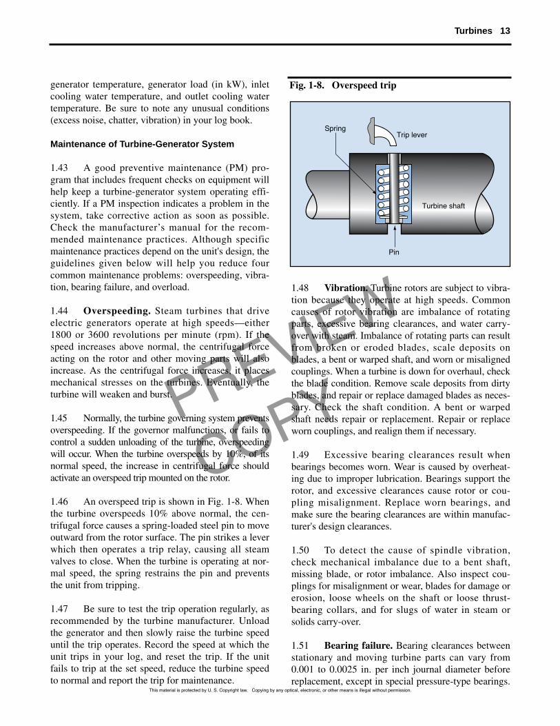
1.45 Normally, the turbine governing system preventsoverspeeding. If the governor malfunctions, or fails tocontrol a sudden unloading of the turbine, overspeedingwill occur. When the turbine overspeeds by 10%, of itsnormal speed, the increase in centrifugal force shouldactivate an overspeed trip mounted on the rotor.
1.46 An overspeed trip is shown in Fig. 1-8. Whenthe turbine overspeeds 10% above normal, the cen-trifugal force causes a spring-loaded steel pin to moveoutward from the rotor surface. The pin strikes a leverwhich then operates a trip relay, causing all steamvalves to close. When the turbine is operating at nor-mal speed, the spring restrains the pin and preventsthe unit from tripping.
1.47 Be sure to test the trip operation regularly, asrecommended by the turbine manufacturer. Unloadthe generator and then slowly raise the turbine speeduntil the trip operates. Record the speed at which theunit trips in your log, and reset the trip. If the unitfails to trip at the set speed, reduce the turbine speedto normal and report the trip for maintenance.
1.48 Vibration. Turbine rotors are subject to vibra-tion because they operate at high speeds. Commoncauses of rotor vibration are imbalance of rotatingparts, excessive bearing clearances, and water carry-over with steam. Imbalance of rotating parts can resultfrom broken or eroded blades, scale deposits onblades, a bent or warped shaft, and worn or misalignedcouplings. When a turbine is down for overhaul, checkthe blade condition. Remove scale deposits from dirtyblades, and repair or replace damaged blades as neces-sary. Check the shaft condition. A bent or warpedshaft needs repair or replacement. Repair or replaceworn couplings, and realign them if necessary.
1.49 Excessive bearing clearances result whenbearings becomes worn. Wear is caused by overheat-ing due to improper lubrication. Bearings support therotor, and excessive clearances cause rotor or cou-pling misalignment. Replace worn bearings, andmake sure the bearing clearances are within manufac-turer's design clearances.
1.50 To detect the cause of spindle vibration,check mechanical imbalance due to a bent shaft,missing blade, or rotor imbalance. Also inspect cou-plings for misalignment or wear, blades for damage orerosion, loose wheels on the shaft or loose thrust-bearing collars, and for slugs of water in steam orsolids carry-over.
1.51 Bearing failure. Bearing clearances betweenstationary and moving turbine parts can vary from0.001 to 0.0025 in. per inch journal diameter beforereplacement, except in special pressure-type bearings.
Turbines 13
Pin
Turbine shaft
Trip leverSpring
Fig. 1-8. Overspeed trip
This material is protected by U. S. Copyright law. Copying by any optical, electronic, or other means is illegal without permission.
PREVIEW
COPY
Examine bearings regularly for wear, wiping, grit-cut-ting, electrolysis (generator bearing), and static elec-trolysis (turbine-end bearing) or thrust. Bearingfailure seriously damages turbines.
1.52 The main cause of bearing failure is improperlubrication. Lubricating oil conducts heat away fromthe bearings and allows the shaft to rotate freely. Youcan prevent bearing failure by supplying the properkind and amount of lubrication, and by keeping theoil in good condition. Follow the manufacturersinstructions. Be sure to keep the oil supply in thereservoir at the proper level.
1.53 Lubricating oil must be free of dirt particlesand water to prevent damage to and corrosion of highly polished bearing surfaces. Oil tends to collect dirt as it flows through the supply system.Lubricating systems that recirculate oil have strainersfilters and purifiers to clean the oil before it re-entersthe turbine. Check these regularly and maintain as required.
1.54 Water leakage into oil lines can contaminateoil and cause bearing failure. A frequent cause ofwater contamination is steam leakage through turbineglands. Keep turbine glands properly maintained andreplace oil if leakage occurs. Another cause of watercontamination is condensed moisture in the sumptank. Check the sump tank daily by drawing off an oilsample to check for water entrainment.
1.55 Turbine overloaded. If a turbine is unableto carry its load, check the daily operating data forindications of trouble. The problem could be causedby a low inlet steam pressure or a high exhaust pressure. If the inlet pressure is low, check the steamsupply valves to be sure that they are providingsteam at the proper pressure. A high exhaust pressure could be caused by dirty condenser tubes,air leakage into the condenser, or warm condensercooling water.
1.56 Other items to check are the steam strainer,governor, and blades. The steam strainer preventslarge solids from entering the turbine at the steamstop valve. Check the strainer for plugging, andremove dirt deposits. The governor might requireadjustment or cleaning. Make sure the governor valvestem is clean and that the valve opens completely.Check fixed and moving blades for clogging, wear,
and damage. Remove dirt from clogged blades;replace worn or damaged ones.
Condenser Cooling Water Requirements
1.57 A condenser requires large quantities ofcooling water to absorb the latent heat of condens-ing steam. In general, a condenser uses between 75and 100 lb of cooling water to condense each poundof steam. Changes in turbine load affect the amountof water needed to maintain the design back pres-sure. If the turbine load decreases below normal,less exhaust steam enters the condenser. Thus, thecondenser requires less water to condense thedecreased supply of steam. If the turbine loadincreases, more exhaust steam flows to the con-denser. Then it requires more cooling water to con-dense the steam at the design exhaust temperatureand back pressure.
1.58 The cooling water inlet temperature mustbe maintained at design temperature for efficientcondenser and turbine operation. If the inlet watertemperature rises above the design temperature,the warmer water will increase the temperature inthe condenser. As the condenser temperature rises,the back pressure also increases. An increase inthe back pressure reduces the pressure dropthrough the turbine, and the steam will performless work.
1.59 Cooling water must circulate through the condenser at a steady rate to maintain the required vacuum. Common causes of reduced water flow areblockage of water intake screens, pump wear, and foul-ing of tube sheets. Intake screens at the cooling watersource (stream, lake, river) trap leaves, wood, and othersuspended solids. If the screens are dirty, the debris willplug the screen openings and restrict water flow into thecondenser. Wear on the impeller of the circulating pumpreduces the amount of water it can send to the con-denser. Tube sheet fouling results when breaks in theintake water screens allow debris to enter the condenser.The debris can plug the inlet ends of the condensertubes and restrict water flow.
1.60 Other factors that reduce condenser efficiencyare dirty tubes, leaking tubes, and air leakage into thesteam space. Dirty (fouled) tubes reduce heat transferfrom the exhaust steam to the cooling water. Leakingtubes allow cooling water to enter the steam space
14 Lesson One
This material is protected by U. S. Copyright law. Copying by any optical, electronic, or other means is illegal without permission.
PREVIEW
COPY
and contaminate the condensate. Air leakagedecreases the vacuum.
1.61 Dirty tubes. Tube fouling occurs when scale,slime, and algae collect on the water side of the tubes.Thick deposits reduce both heat transfer and water flowthrough the condenser. You can clean tubes with ahydraulic gun, by chemical treatment, or bybackwashing. A hydraulic gun shoots rubber plugsthrough the tubes with a water jet. The plugs rubagainst the tube walls, and dislodge slime and softscale. You can remove deposits chemically by addingchlorine or chlorine compounds to the water supply ona regular schedule. The chlorine destroys algae andreduces slime buildup. Backwashing reverses the waterflow which flushes out the inlet ends of the tubes.
1.62 Tube leakage. Leakage occurs when tube endspull away from the tube sheet and when tubes split orcrack. You can detect tube leakage in several ways. Onecommon method is to slant down the condenser (exceptfor the steam jets) and pass a lighted candle around thetubes and tube sheets. If there is a leak, the candle flamewill flicker or go out. Another way to detect leaks is toshut down the condenser and circulate water throughthe tubes. Water will drip through the tubes if leaks arepresent. Or, you can fill the steam space (instead of thetubes) with water. Water will collect in the water boxesif tubes are leaking.
1.63 These methods will tell you if large leaks arepresent, but small leaks are more difficult to find. Oneway to check for small leaks is to measure the conductivity of the condensate with a conductivitymeter. Condensate is high quality water that containsfew dissolved minerals (ions), and has a low electricalconductivity. Cooling water contains a higher concen-tration of dissolved minerals and has a higher electricalconductivity. If cooling water has leaked into the con-densate, it will increase the condensate's electrical con-ductivity and that will show on the meter.
1.64 Repair tube leaks as soon as possible afteryou discover them. When the condenser is down forshort maintenance periods, you can repair a split tubeby inserting a fiber or metal plug into the tube end.When the condenser is down for an extended period,replace damaged tubes.
1.65 Air leakage. Because a condenser is undervacuum, air tends to leak through seals, joints, and
condensate lines. It is also possible for air to enterthe condenser through leaks in the cooling watertubes. Any air remaining in the condenser forms afilm or blanket on condenser tubes. This filmreduces heat transfer. Air leakage will decrease orruin the vacuum.
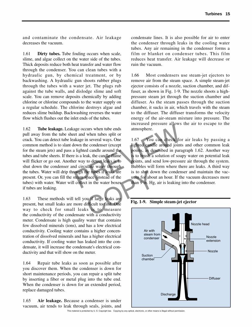
1.66 Most condensers use steam-jet ejectors toremove air from the steam space. A simple steam-jetejector consists of a nozzle, suction chamber, and dif-fuser, as shown in Fig. 1-9. The nozzle shoots a high-pressure steam jet through the suction chamber anddiffuser. As the steam passes through the suctionchamber, it sucks in air, which travels with the steamto the diffuser. The diffuser transforms the velocityenergy of the air-steam mixture into pressure. Theincreased pressure allows the air to escape to theatmosphere.
1.67 You can check for air leaks by passing alighted candle around joints and other common leakpoints, as described in paragraph 1.62. Another wayis to brush a solution of soapy water on potential leakpoints, and send low-pressure air through the system.Bubbles will form where there are leaks. A third wayis to shut down the condenser and maintain the vac-uum for about an hour. If the vacuum decreases morethan 9 in. Hg, air is leaking into the condenser.
Turbines 15
This material is protected by U. S. Copyright law. Copying by any optical, electronic, or other means is illegal without permission.
Air withsteam fromcondenser
Suctionchamber
Discharge
Diffuser
Nozzle
Nozzleextension
Nozzle head
Fig. 1-9. Simple steam-jet ejector
Water in
Air Air
Out
CondenserCirculating pump
Steam turbine
Dischargepipe
Hotwell
Condenser
Impeller
Circulatingpump
Circulating waterintake tunnel
Circulating wateroutlet tunnel
PREVIEW
COPY
16 Lesson One
This material is protected by U. S. Copyright law. Copying by any optical, electronic, or other means is illegal without permission.
Cooling Water System
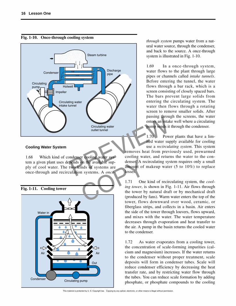
1.68 Which kind of condenser cooling water sys-tem a given plant uses depends on the available sup-ply of cool water. The two kinds of systems areonce-through and recirculation systems. A once-
through system pumps water from a nat-ural water source, through the condenser,and back to the source. A once-throughsystem is illustrated in Fig. 1-10.
1.69 In a once-through system,water flows to the plant through largepipes or channels called intake tunnels.Before entering the tunnel, the waterflows through a bar rack, which is ascreen consisting of closely spaced bars.The bars prevent large solids fromentering the circulating system. Thewater then flows through a rotatingscreen to remove smaller solids. Afterpassing through the screens, the waterenters an intake well where a circulatingpump sends it through the condenser.
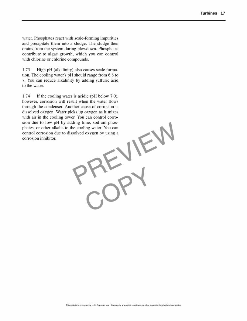
1.70 Power plants that have a lim-ited water supply available for coolinguse a recirculating system. This system
removes heat from previously used, prewarmedcooling water, and returns the water to the con-denser. A recirculating system requires only a smallamount of makeup water (5 to 10%) to replacelosses.
1.71 One kind of recirculating system, the cool-ing tower, is shown in Fig. 1-11. Air flows throughthe tower by natural draft or by mechanical draft(produced by fans). Warm water enters the top of thetower, flows downward over wood, ceramic, orfiberglass strips, and collects in a basin. Air entersthe side of the tower through louvers, flows upward,and mixes with the water. The water temperaturedecreases through evaporation and heat transfer tothe air. A pump in the basin returns the cooled waterto the condenser.
1.72 As water evaporates from a cooling tower,the concentration of scale-forming impurities (cal-cium and magnesium) increases. If the water returnsto the condenser without proper treatment, scaledeposits will form in condenser tubes. Scale willreduce condenser efficiency by decreasing the heattransfer rate, and by restricting water flow throughthe tubes. You can reduce scale formation by addingphosphate, or phosphate compounds to the cooling
Fig. 1-10. Once-through cooling system
Fig. 1-11. Cooling tower
PREVIEW
COPY
Turbines 17
water. Phosphates react with scale-forming impuritiesand precipitate them into a sludge. The sludge thendrains from the system during blowdown. Phosphatescontribute to algae growth, which you can controlwith chlorine or chlorine compounds.
1.73 High pH (alkalinity) also causes scale forma-tion. The cooling water's pH should range from 6.8 to7. You can reduce alkalinity by adding sulfuric acidto the water.
1.74 If the cooling water is acidic (pH below 7.0),however, corrosion will result when the water flowsthrough the condenser. Another cause of corrosion isdissolved oxygen. Water picks up oxygen as it mixeswith air in the cooling tower. You can control corro-sion due to low pH by adding lime, sodium phos-phates, or other alkalis to the cooling water. You cancontrol corrosion due to dissolved oxygen by using acorrosion inhibitor.
This material is protected by U. S. Copyright law. Copying by any optical, electronic, or other means is illegal without permission.
PREVIEW
COPY
1-9. The condensing temperature decreasesas the vacuum .
1-10. The efficiency of the boiler-turbine-gen-erator unit equals the ratio of the electri-cal energy output to the input.
1-11. Turbine overspeeding can occur whenthe malfunctions.
1-12. Excessive bearing clearances causemisalignment of the or coupling.
1-13. Two main causes of lubricating oil contamination are dirt and
leakage.
1-14. You can clean condenser tubes with ahydraulic gun, with chlorine, or by .
1-15. A steam-jet ejector is a device com-monly used to remove from a condenser.
1-16. Scale reduces condenser efficiency byrestricting water flow and reducing therate of .
1-9. INCREASES
Ref: 1.35, Table 1-1
1-10. HEAT
Ref: 1.38
1-11. GOVERNOR
Ref: 1.45
1-12. ROTOR
Ref: 1.49
1-13. WATER
Ref: 1.54
1-14. BACKWASHINGBackwashing reverses the water flow through the condenser.
Ref: 1.61
1-15. AIR
Ref: 1.66
1-16. HEAT TRANSFER
Ref: 1.72
18 Programmed Exercises
This material is protected by U. S. Copyright law. Copying by any optical, electronic, or other means is illegal without permission.
PREVIEW
COPY
1-1. The moving blades of a turbine connect towhich of the following?
� a. Cylinder� b. Diaphragm� c. Disc or drum� d. Stator
1-2. What kind of turbine rotates the shaft usingthe kickback force of the steam?
� a. Pressure-compounded impulse� b. Reaction� c. Simple impulse� d. Velocity-compounded impulse
1-3. A turbine that has two steam paths and hasits high-pressure and low-pressure sectionson a single shaft is classed as
� a. cross-compound, double flow� b. cross-compound, reheat � c. tandem-compound, double flow� d. tandem-compound, single flow
1-4. A condenser allows steam to perform morework in the turbine by
� a. decreasing the pressure drop� b. increasing the back pressure � c. increasing the condensing
temperature� d. increasing the pressure drop
1-5. If the circulating water temperature in a con-denser rises 5° F. each pound of waterabsorbs how much heat?
� a. 1 Btu� b. 5 Btu� c. 10 Btu� d. 15 Btu
1-6. Which of the following activates an overspeedtrip?
� a. Decrease in bearing clearances� b. Decrease in centrifugal force� c. Decrease in turbine speed� d. Increase in centrifugal force
1-7. Which of the following will result if the con-denser inlet water temperature rises abovethe design temperature?
� a. Back pressure will decrease� b. Pressure drop through the turbine will
decrease� c. The amount of work performed by the
steam will increase� d. The temperature in the condenser
will remain the same
1-8. You can use a conductivity meter to check for
� a. condenser air leakage � b. condenser tube leakage � c. improper bearing clearances� d. worn turbine blades
1-9. A cooling tower removes heat from water bymeans of
� a. air � b. cold water � c. jet ejectors� d. special oils
1-10. You can control condenser tube corrosiondue to low pH by adding which of the follow-ing to the cooling water?
� a. Calcium� b. Dissolved oxygen� c. Lime� d. Sulfuric acid
Self-Check Quiz 19
Answer the following questions by marking an “X”in the box next to the best answer.
This material is protected by U. S. Copyright law. Copying by any optical, electronic, or other means is illegal without permission.
PREVIEW
COPYAnswers to Self-Check Quiz
1-1. c. Disc or drum. Ref: 1.04
1-2. b. Reaction. Ref: 1.10
1-3. c. Tandem-compound, double flow.Ref: 1.20
1-4. d. Increasing the pressure drop.Ref: 1.30
1-5. b. 5 Btu. Ref: 1.36
1-6. d. Increase in centrifugal force.Ref: 1.44,1.45.
1-7. b. Pressure drop through the turbine will decrease. Ref: 1.58
1-8. b. Condenser tube leakage.Ref: 1.63
1-9. a. Air. Ref: 1.71
1-10. c. Lime. Ref: 1.74
A turbine is a machine that generates mechanicalpower from the kinetic energy of a fluid. Steamturbines are the most widely used kind. A steamturbine’s two main parts are the cylinder and therotor. In an impulse turbine, the impact force ofthe steam jet on the blades turns the shaft.Impulse turbines can be velocity compounded orpressure-compounded. A reaction turbine usesthe kickback force of the steam to rotate the shaft.Steam turbines can be classified not only byblade design, but also by exhaust conditions,steam path, or shaft arrangement.
Gas turbines and steam turbines operate on simi-lar principles. A gas turbine, however, uses airinstead of steam as its working fluid. A gas tur-bine converts the chemical energy of a fuel intomechanical energy through internal combustion.
A condenser is a heat-transfer device located atthe turbine exhaust. It uses cooling water to con-dense steam. The two kinds of condenser aredirect contact and indirect contact. Direct-contact
condensers mix the steam directly with sprays of cooling water. The condensate from an indi-rect-contact condenser does not mix with thecooling water.
The largest single loss of energy in a power plantis the heat rejected to the condenser. The efficiency of the boiler-turbine-generator unitequals the ratio of the energy output to theenergy input. Good preventive maintenance isyour best tool in keeping a turbine-generator system operating efficiently. Common mainte-nance problems are overspeeding, vibration,bearing failure, and overload.
The kind of condenser cooling water system usedin a given plant depends on the available supplyof cool water. A once-through system pumpswater from a natural source, through the con-denser, and back to the source. In a recirculatingsystem, the cooling water is returned to the con-denser. It is commonly used when a limitedamount of water is available for cooling.
20 Lesson One
SUMMARY
This material is protected by U. S. Copyright law. Copying by any optical, electronic, or other means is illegal without permission.