Embed Size (px)
Citation preview
Using SimDesigner on Convertible Top Latch Mechanism
Stephen Doncov – ASC Incorporated –CAE Specialist
John Ellison – MSC.Software –Application Engineer
-add your logo here-About ASC: History
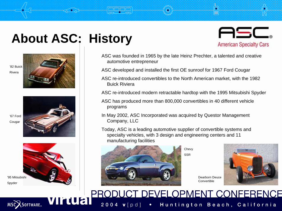
ASC was founded in 1965 by the late Heinz Prechter, a talented and creative automotive entrepreneur
ASC developed and installed the first OE sunroof for 1967 Ford Cougar
ASC re-introduced convertibles to the North American market, with the 1982 Buick Riviera
ASC re-introduced modern retractable hardtop with the 1995 Mitsubishi Spyder
ASC has produced more than 800,000 convertibles in 40 different vehicle programs
In May 2002, ASC Incorporated was acquired by Questor ManagementCompany, LLC
Today, ASC is a leading automotive supplier of convertible systems and specialty vehicles, with 3 design and engineering centers and 11manufacturing facilities
’67 Ford
Cougar
’82 Buick
Rivera
’95 Mitsubishi
Spyder
Chevy
SSR
Dearborn Deuce Convertible
-add your logo here-Objective:
To Perform a Virtual DVP on a Header Latch System
• Identify Areas/Specifications of Non-Conformance• Provide Feedback to Design Engineering for Changes• Get Closer to a Design-Analyze-Confirm mode and away
from Design-Build-Test• Save Time & Money
-add your logo here-Approach:
Utilize CATIA V5 FEA/DMU Kinematics and SimDesigner Motion/NonLineartools for all CAE even though design is based in CATIA V4.
Why?• Through evaluation, V5 analysis tools are robust, fast and easy to use. • Time lost in converting V4 models to V5 made up with productivity of V5.• CAE group preparing for migration to V5 and SimDesigner Products. We
will be leading ASC forward!• SimDesigner NonLinear expands ASC’s CAE capability and maintains goal
of utilizing integrated products.• Common V5 Database allows ASC to utilize completed V5 analysis models
performed by MSC.Software.
-add your logo here-Background:
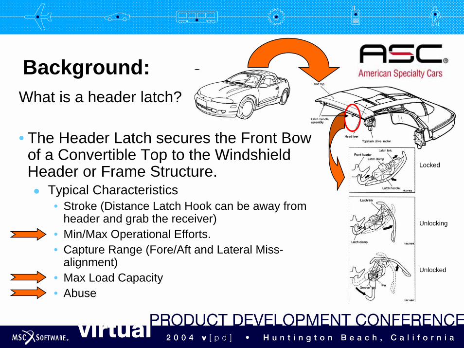
What is a header latch?
• The Header Latch secures the Front Bow of a Convertible Top to the Windshield Header or Frame Structure.
Typical Characteristics• Stroke (Distance Latch Hook can be away from
header and grab the receiver)• Min/Max Operational Efforts.• Capture Range (Fore/Aft and Lateral Miss-
alignment)• Max Load Capacity• Abuse
Locked
Unlocking
Unlocked
-add your logo here-
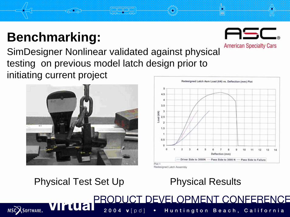
Benchmarking:SimDesigner Nonlinear validated against physical testing on previous model latch design prior to initiating current project
Physical Test Set Up Physical Results
-add your logo here-
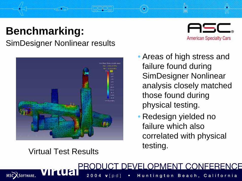
Benchmarking:SimDesigner Nonlinear results
• Areas of high stress and failure found during SimDesigner Nonlinear analysis closely matched those found during physical testing.
• Redesign yielded no failure which also correlated with physical testing.
Virtual Test Results
-add your logo here-
Benchmarking: Abuse and Ultimate Load AnalysesUse SimDesigner Nonlinear for requirements where the
ultimate strength value could be exceeded:• Benchmark of prior model design provided confidence in
results.• Benchmark provides insight into establishing failure
points.• Analytically test design (Virtual DVP&R) prior to physical
testing and construction of tools for manufacturing.• Verify criteria for acceptable design.
-add your logo here-Requirements:
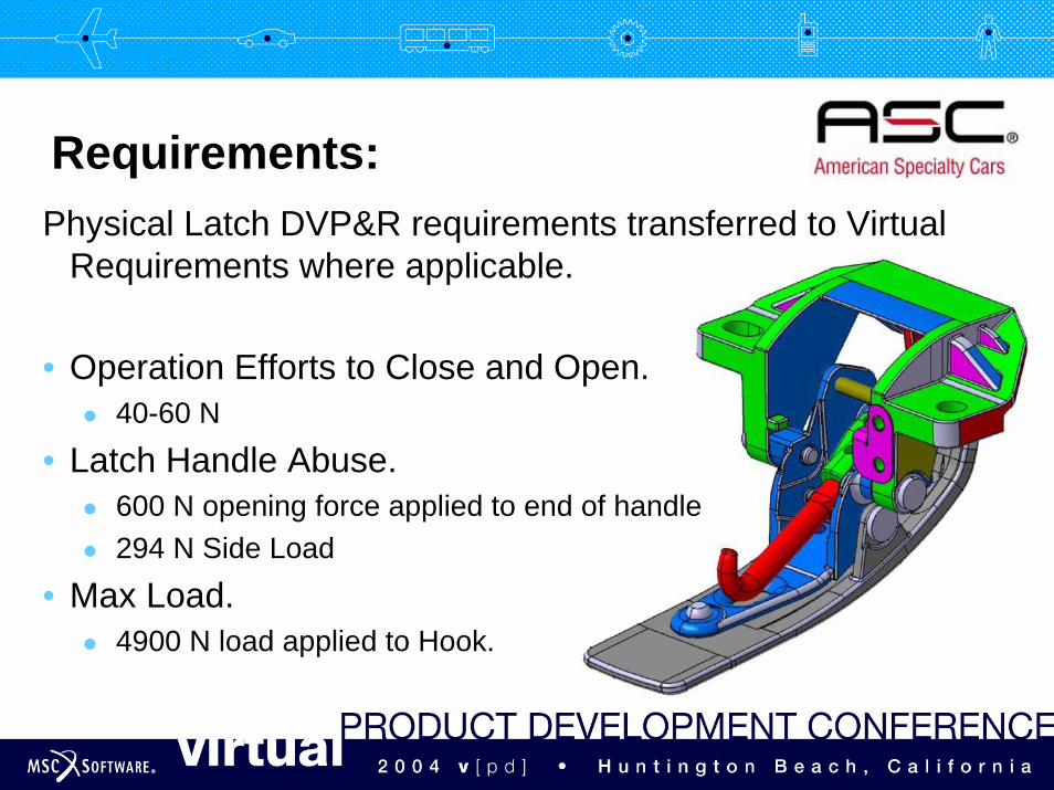
Physical Latch DVP&R requirements transferred to Virtual Requirements where applicable.
• Operation Efforts to Close and Open.40-60 N
• Latch Handle Abuse.600 N opening force applied to end of handle294 N Side Load
• Max Load.4900 N load applied to Hook.
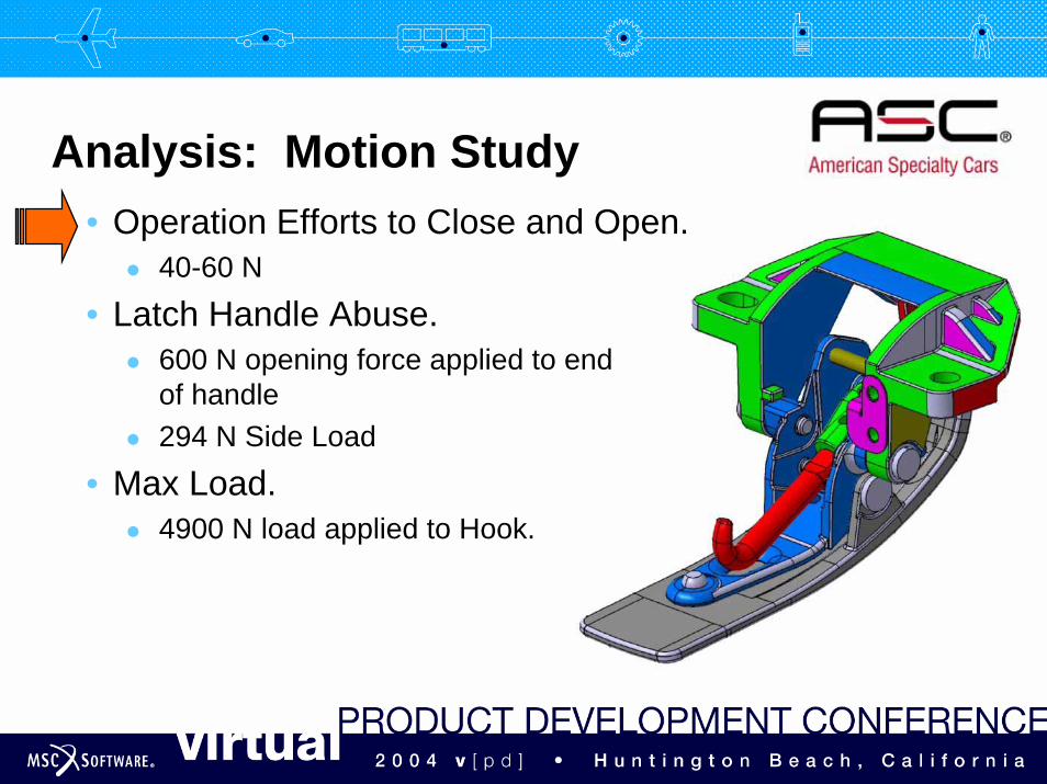
-add your logo here-Analysis: Motion Study
• Operation Efforts to Close and Open.40-60 N
• Latch Handle Abuse.600 N opening force applied to end of handle294 N Side Load
• Max Load.4900 N load applied to Hook.
-add your logo here-
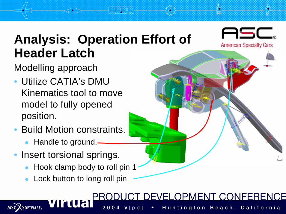
Modelling approach• Utilize CATIA’s DMU
Kinematics tool to move model to fully opened position.
• Build Motion constraints.Handle to ground.
• Insert torsional springs.Hook clamp body to roll pin 1Lock button to long roll pin
Analysis: Operation Effort of Header Latch

-add your logo here-
Modelling approach• Approximate leaf springs
using linear springs/dampers.
Handle detent springHandle to idler spring
Analysis: Operation Effort of Header Latch
-add your logo here-
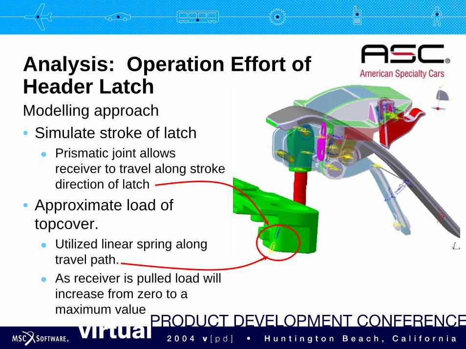
Modelling approach• Simulate stroke of latch
Prismatic joint allows receiver to travel along stroke direction of latch
• Approximate load of topcover.
Utilized linear spring along travel path.As receiver is pulled load will increase from zero to a maximum value
Analysis: Operation Effort of Header Latch
-add your logo here-
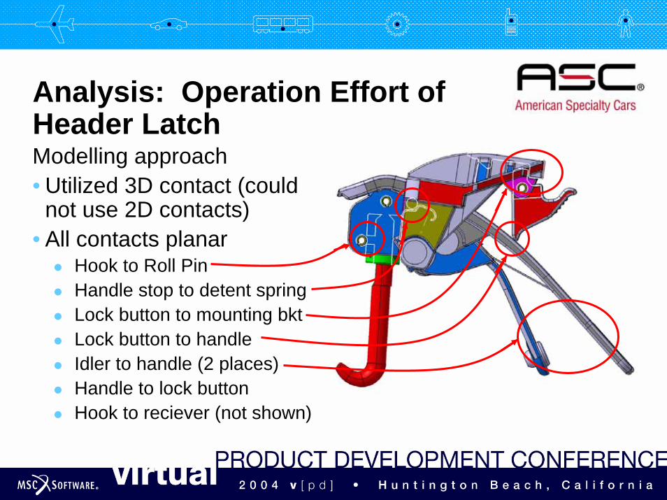
Modelling approach• Utilized 3D contact (could
not use 2D contacts)• All contacts planar
Hook to Roll PinHandle stop to detent springLock button to mounting bktLock button to handleIdler to handle (2 places)Handle to lock buttonHook to reciever (not shown)
Analysis: Operation Effort of Header Latch
-add your logo here-
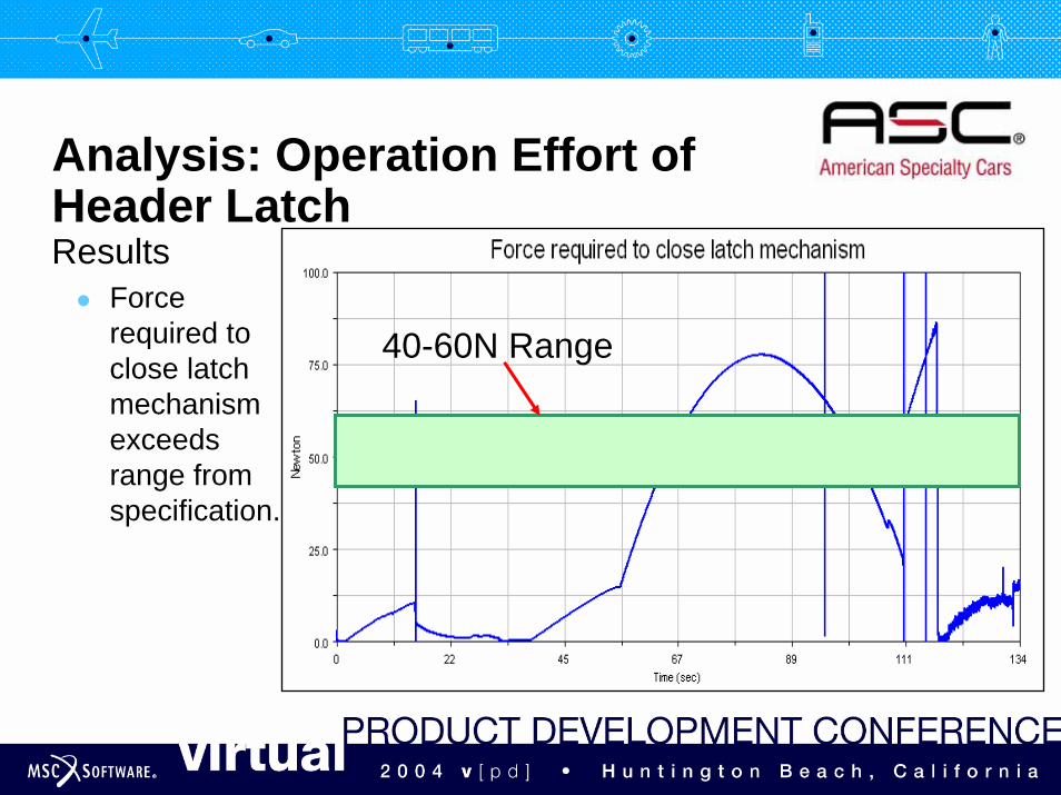
ResultsForce required to close latch mechanism exceeds range from specification.
Analysis: Operation Effort of Header Latch
40-60N Range
-add your logo here-
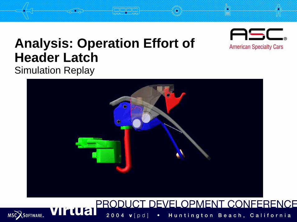
Simulation Replay
Analysis: Operation Effort of Header Latch
-add your logo here-
What did we learn?• Motion study confirmed operation of latching system.
Interaction of Latch Handle and Idler Bracket.Verified latch capture range (latch stroke).Verified operation of handle lock.
• Handle efforts exceeded requirement.Finer hook adjustment needed to reduce handle efforts.Leaf springs too stiff (Handle Detent, Handle to Idler).
• Discovered issue with 2D Contacts.
Analysis: Motion Study Results
-add your logo here-
2D contacts vs. 3D contacts.• Latch assembly contains many contacts which are planar.• Latch contacts ideally should be modelled as 2D contacts.
KISS approach.• 2D contacts compute much faster than 3D contacts.
Essential for complex Mechanisms.• We could not use 2D contacts because we kept getting a
“curves are not co-planar” • Generated CR 47465 to address the issue.• We use 2D contacts often and this issue needs resolution.
Analysis: 2D Contact Issue
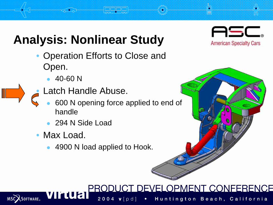
-add your logo here-Analysis: Nonlinear Study
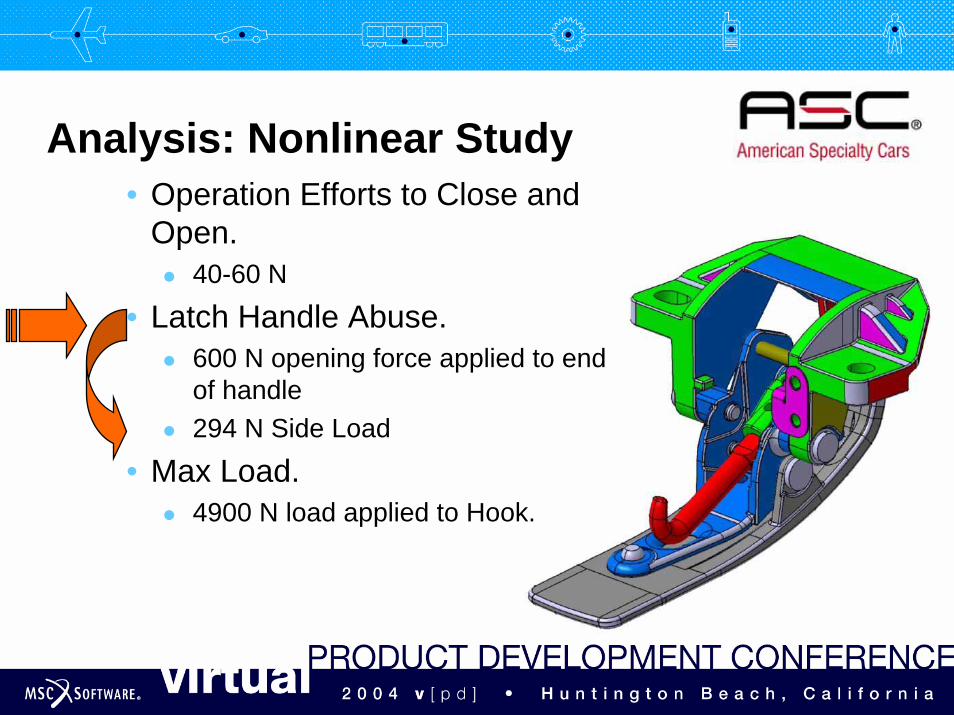
• Operation Efforts to Close and Open.
40-60 N
• Latch Handle Abuse.600 N opening force applied to end of handle294 N Side Load
• Max Load.4900 N load applied to Hook.
-add your logo here-Latch Handle Vertical Abuse
Modelling approach for 600N vertical load analysis• Use SimDesigner Linear analysis to determine which parts
could be omitted from the SimDesigner Nonlinear analysisParts that did not reach yield strength and were not critical tomaintain the integrated of the mechanism (i.e. connecting pins) were eliminated• Omitted the clamp_body, detent)spring, handle_spring, hook, receiver,
rubber_stop, and both roll_pin_1 and roll_pin_2
-add your logo here-Latch Handle Vertical Abuse
Modelling approach for 600N vertical load analysis• Meshing
All parts were original meshed with tet4’s.Ran a SimDesigner Nonlinear analysis to identify where the hot spots for high stress might be.The hot spots were found to be in the handle part• All parts except handle remained tet4’s but local mesh and local sag
conditions were implement around the areas of contact• Handle was set to tet10 meshing and local mesh and local sag conditions
were implement around the areas of contact and the hot spots
Encountered issue with combining Tet4/Tet10 in R13 • Correction to MSC.Marc solver has been implemented and will be
available soon
-add your logo here-Latch Handle Vertical Abuse
Modelling approach for 600N vertical load analysis• Boundary Conditions
Constraints • Clamp mounting bracket and both handle_to_idler_hinge pins.
Contact • Set to Inactive for bodies that would not collide and to eliminate
consideration of bodies contact themselves.• Set to Glue for bodies that did not need to rotate or translate relative one
another.• Set to Touch for bodies that could come in and out of contact with one
another or would need to rotate or translated relative to one another.Loading• Apply 600 N load in vertical direction to face near handle end
-add your logo here-Latch Handle Vertical Abuse
Modelling approach for 600N vertical load analysis• Material Properties
ZA8 – Zinc used for all components except the connector pins were model as 1010 – SteelNonlinear material curves were provided by customer although theexactness of the curves was not validated with physical testing• It’s critical that the exact treatment of each material is consider as any
amount of cold-working or heat treatment can lower or raise the yield and ultimate strength and dramatically effect the nonlinear material curve
Solver Settings• Contact bias at 90% and Coulomb friction activated
-add your logo here-Latch Handle Vertical Abuse
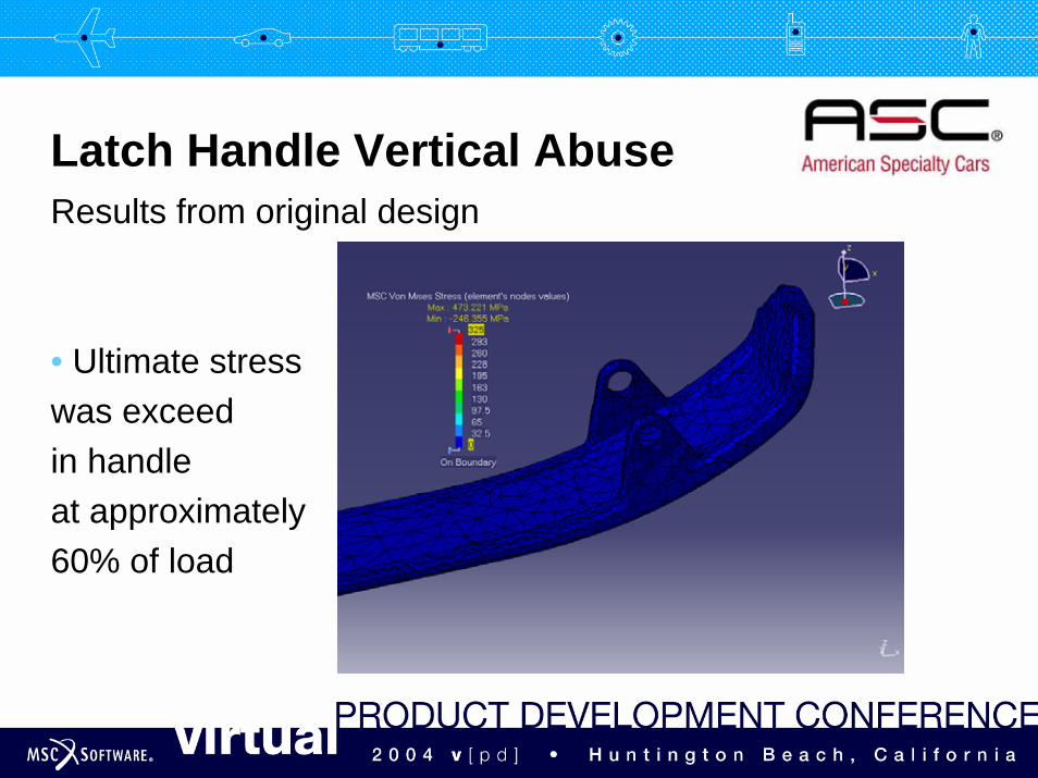
Results from original design
• Ultimate stress was exceed in handle at approximately60% of load

-add your logo here-Latch Handle Vertical Abuse
Results from modified design.
• Handle satisfies vertical abuse specification.
-add your logo here-Analysis: Nonlinear Study
• Operation Efforts to Close and Open.
40-60 N
• Latch Handle Abuse.600 N opening force applied to end of handle294 N Side Load
• Max Load.4900 N load applied to Hook.
-add your logo here-Latch Handle Side Load Abuse
Modelling approach for 294N side load analysis• Same boundary conditions, material properties, meshing,
solver settings as 600N vertical load analysis• Omitted the lock_button and long_roll_pin, in addition to,
the parts omitted for the 600N vertical load analysis
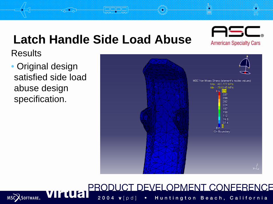
-add your logo here-Latch Handle Side Load Abuse
Results• Original design satisfied side load abuse design specification.

-add your logo here-Analysis: Nonlinear Study
• Operation Efforts to Close and Open.
40-60 N
• Latch Handle Abuse.600 N opening force applied to end of handle294 N Side Load
• Max Load.4900 N load applied to Hook.
-add your logo here-
<<4900N>> load in latch stroke directionModelling approach for 4900N load analysis• Use SimDesigner Linear analysis to determine which parts
could be omitted from the SimDesigner Nonlinear analysisParts that did not reach yield strength and were not critical tomaintain the integrated of the mechanism (i.e. connecting pins) were eliminated• Omitted all parts except the clamp_body, hook, roll_pin_1 and receiver
-add your logo here-
<<4900N>> load in latch stroke directionModelling approach for 4900N load analysis• Meshing
All parts were original meshed with tet4’s.Ran a SimDesigner Nonlinear analysis to identify where the hot spots for high stress might be.• Tet4 meshing on receiver and roll pin• Tet10 meshing used on clamp_body and hook• Local mesh and local sag conditions were implement around the areas of
contact and the hot spots
-add your logo here-
<<4900N>> load in latch stroke directionModelling approach for 4900N load analysis• Boundary Conditions
Constraints • Applied advanced restraint to roll_pin_1 allowing only translational
displacement in latch stroke direction • No consideration was made of rotational DOFs
Encountered issue with applying advance restraints in non-global axes system • Workaround was to change orientation of assembly to align latch stroke
direction with a principal axis.• Feature to be included in future release.
-add your logo here-
<<4900N>> load in latch stroke directionModelling approach for 4900N load analysis• Boundary Conditions
Contacts• Used inactive, glue, and touch as described in 600N latch abuse analysis
Encountered issue with overlapping volume of clamp body and hook• Initial interference was interpreted as an undesired pressure force • Workaround was to modify hook volume to eliminate interference• Product Development is working to include this functionality in the future
-add your logo here-
<<4900N>> load in latch stroke directionModelling approach for 4900N load analysis• Boundary Conditions
Loading• Applied distributed force of 4900 across roll pin in latch stroke direction
Encountered issue with modelling roll_pin_1 as rigid body • Initial intention was to apply an enforced displacement to a rigid
roll_pin_1 as the flexibility of roll_pin_1 was determined negligible • This option was negated as it is not currently possible to post process
reaction loads on rigid bodies solely within SimDesigner Nonlinear making it impossible to know at what displacement the 4900N requirement was achieved
• Product Development is working to include this functionality in the future
-add your logo here-
Modelling approach for 4900N load analysis• Material Properties
ZA8 – Zinc : Clamp Body1010 – Steel : Roll Pin 4130 – Steel : Receiver12L14 – Steel : Hook
• Solver SettingsContact bias at 90% and Coulomb friction activated
<<4900N>> load in latch stroke direction
-add your logo here-
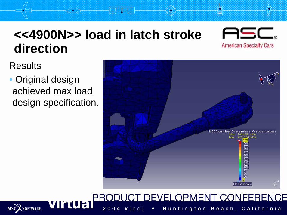
<<4900N>> load in latch stroke direction
Results• Original design achieved max load design specification.
-add your logo here-Conclusions
Significance of Work• By utilizing Design-Analyze-Confirm for approach, failure
points in the handle were identified and addressed; essentially replacing the first stage of physical prototyping and testing.
• A substantial amount of time and money was saved by determining early on the weak areas in the initial design which would not meet spec.
• Testing is done to confirm results. Failures trying to meet specifications can be troubling to customers. Performing a test to confirm predicted success scores big confidence points with customers!
-add your logo here-Conclusions
Benefits of SimDesigner for CATIA V5• One common interface and database that can be shared
by designers and analysts.• Seamless transition between CATIA design and analysis
and MSC.Software technology.• Issues identified in software. When you have to use your
own tools and things don’t work, issues become real. Important to getting resolution to issues.