Embed Size (px)
Citation preview

Using optical mouse sensors forsheet position measurement
W.P.H. Kamphuis
DCT 2007.20
Traineeship report
Coach(es): ir. B.H.M. Bukkemsir. P. van den Bosch (Océ)
Supervisor: dr. ir. M.J.G. van de Molengraft
Technische Universiteit EindhovenDepartment Mechanical EngineeringDynamics and Control Technology Group
Eindhoven, February, 2007

ii
Summary
In this report the possibility of using optical mouse sensors as contactlesssheet displacement sensors is investigated. This report is written as a manual,to setup a computer to measure displacement with an optical mouse.
Chapter 2 describes the working principle of an optical mouse. The spec-ifications of the displacement sensor for use in the experimental setup of apaperpathare are formulated. An optical mouse sensor is chosen that meetsthese specifications, and an optical mouse using this mouse sensor is chosen.
Chapter 3 describes the method for acquiring and using the mouse data,and can be used as setup manual. The adjustment of the resolution setting(the number of counts a movement of one inch generates) is described andthe setup of the software to adjust this is also explained.
Chapter 4 describes the programs that are used for obtaining the measure-ment data in a suitable format. Some important designing issues of the pro-grams are explained. The use of these programs is explained, and the resultsof some measurements are shown.
The report ends with some Conclusions and Recommendations.
iii

iv SUMMARY

Contents
Summary iii
1 Introduction 1
2 The optical mouse 32.1 Components of an optical mouse . . . . . . . . . . . . . . . . . 3
2.1.1 The optical system . . . . . . . . . . . . . . . . . . . . . 32.1.2 The mouse sensor . . . . . . . . . . . . . . . . . . . . . 52.1.3 The microcontroller . . . . . . . . . . . . . . . . . . . . 8
2.2 Optical mouse measurement specifications . . . . . . . . . . . 92.3 Mouse sensor choice . . . . . . . . . . . . . . . . . . . . . . . . 11
3 Acquiring and using mousedata 153.1 Pollingrate . . . . . . . . . . . . . . . . . . . . . . . . . . . . . 153.2 The USB connection . . . . . . . . . . . . . . . . . . . . . . . . 153.3 The operating system . . . . . . . . . . . . . . . . . . . . . . . 173.4 Linux setup . . . . . . . . . . . . . . . . . . . . . . . . . . . . . 18
3.4.1 Knoppix installation options . . . . . . . . . . . . . . . 193.4.2 Replacing the mousedriver in the Kernel . . . . . . . . 20
3.5 Using modules . . . . . . . . . . . . . . . . . . . . . . . . . . . 213.5.1 Reading the mouse data . . . . . . . . . . . . . . . . . . 22
3.6 Adjusting the mouse resolution . . . . . . . . . . . . . . . . . . 23
4 Programming 254.1 Accuracy . . . . . . . . . . . . . . . . . . . . . . . . . . . . . . 254.2 The measurement programs design . . . . . . . . . . . . . . . 264.3 Using the measurement program . . . . . . . . . . . . . . . . . 284.4 Measurement results . . . . . . . . . . . . . . . . . . . . . . . . 29
5 Conclusions & Recommendations 335.1 Conclusion . . . . . . . . . . . . . . . . . . . . . . . . . . . . . 33
v

5.2 Recommendations . . . . . . . . . . . . . . . . . . . . . . . . . 33
A Specs MX518 37
B LMCTL program 39B.1 lmctl.c adjustments . . . . . . . . . . . . . . . . . . . . . . . . 39B.2 cmdline.c adjustments . . . . . . . . . . . . . . . . . . . . . . . 41
C Program source 43C.1 possens.c . . . . . . . . . . . . . . . . . . . . . . . . . . . . . . 44C.2 startchoice.c . . . . . . . . . . . . . . . . . . . . . . . . . . . . 45C.3 calibrate.c . . . . . . . . . . . . . . . . . . . . . . . . . . . . . . 47C.4 measure.c . . . . . . . . . . . . . . . . . . . . . . . . . . . . . . 53
D Measurements 57D.1 Analyzed measurement results . . . . . . . . . . . . . . . . . . 61

Chapter 1
Introduction
In numerous applications it is needed to obtain position or speed informationof a moving object. To prevent the measuring device from influencing themotion, a contactless motion sensor is needed. Most of these sensors are veryexpensive, partly because they are not mass products.
Nowadays there is a mass produced cheap contactless motion measuringdevice on the market. This device, however, is not used as a sensor but as ahuman interface device (HID) for a personal computer: the optical mouse sen-sor. The mice with the highest performance, i.e. highest resolution, updatefrequency1, speed, and acceleration, are mouse sensors used in gamingmice.Their users have very high demands on speed and accuracy. Since these de-mands correspond to the demands on contactless motion sensors, the use ofmouse sensors used in optical gaming mice as contactless motion sensorsmight be a serious option.
This report presents the results of the study towards the usability of an or-dinary gamingmouse as a contactless motion sensor. The problem statemenetof this study can be formulated as follows:“Can an optical mouse be used as a contactless motion sensor?” Which opticalmice can be used. After making the selection this report can also be used as aninstallation manual to be able to receive the displacement data of the mouse.This study encompasses
1. the analysis of the mouse.
2. the analysis of the data communication of the mouse.
3. the interpretation of the data received by the computer. The computer
1Also known as the polling-rate the time between two polls. A poll is the transmissionof a data set. A polling-rate of 2 ms means the data sets are send 500 times per second.(An interval of 500 Hz)
1

2 CHAPTER 1. INTRODUCTION
has to interpret the received data as a motion measurement instead ofinput from a HID.
(a) A suitable operating system has to be chosen.
(b) The mousedriver has to be adjusted.
4. the design of a program to read the mousedata.
This report is organised as follows: Chapter 2 the optical mouse is analysedto understand how this device measures motion. In Paragraph 2.3 a suitablemouse is chosen. In Chapter 3 the connection of the mouse to the computeris explained and how the computer has to be setup to communicate with themouse. In Chapter 4 it is explained how the measuring programmust be usedand some important issues of the design of the program are explained. Thereport finishes with Chapter 5 Conclusions & Recommendations.

Chapter 2
The optical mouse
The mouse is a human interface device for a personal computer. The move-ment of the device is measured and results in a displacement of the mousepointer on the screen. In this report we only consider contactless optical micebecause a trackball or the conventional mouse, with a rolling rubber ball onthe surface, are not contactless. The optical mouse uses, as implicated by itsname, an optical device to measure displacement. The measuring system hasno moving parts, does not make contact with the surface, and needs no main-tenance. The main components of an optical mouse and their function willbe explained first[8, 10], afterwhich the specifications the mouse has to satisfywill be discussed.
2.1 Components of an optical mouse
The components an optical mouse needs to measure displacement are an op-tical system, mouse sensor, and a microcontroller. These components are de-scribed in the following subsections.
2.1.1 The optical system
The optical system consists mainly of three parts:
• Lens
• Lightsource
• Mouse sensor
These parts are shown in Figure 2.1, together with some other parts neededfor the assembly, i.e. the custom baseplate, custom printed circuit board (PCB)
3

4 CHAPTER 2. THE OPTICAL MOUSE
and the clip. The lens is the largest part and is mounted on the base plate ofthe mouse. It transports the light from the light source towards the surface tobe measured and projects a surface image on the mouse sensor. In Figure 2.2this is shown schematically and Figure 2.3 shows the actual optical path in anassembled optical mouse.
LightsourceClipMouse sensor
Custom PCB
Lens
Custum baseplate
Figure 2.1: Optical mouse components[8]
Figure 2.2: Optical system in use[9]
The light source is either a LED (Light Emitting Diode) or a VCSEL (Single-Mode Vertical-Cavity Surface Emitting Laser). The mouse sensor takes grayscale images of the underlying surface. These images vary from 16×16 pixelsto 30 × 30 pixels, depending on the image sensor used. Image detail doesnot only depend on the image size but also depends on lens quality and thewavelength and corresponding colour of the light source. The light colourcan affect the contrast of the surface image: for instance details are better rec-ognized with red light, than with blue light for instance. In Figure 2.4 therelative respons1 of the mouse sensor, to different wavelengths (light colours),is shown. Table 2.1 shows the wavelengths and corresponding colours, theavailable LED’s and their operating wavelength’s are arranged by colour. Therespons of the ADNS-3080 mouse sensor is taken as an example. A red LEDwith a wavelength of approximately 630 nm gives maximum response. This
1The maximum respons is set to 1, the respons at other wavelengths is related to thismaximum.

2.1. COMPONENTS OF AN OPTICAL MOUSE 5
Table 2.1: Wavelengths[10]The visible light spectrum 400 to 750 nm
Wavelength LED’s AvailableRange (nm) Colour (nm)(100-400) Ultraviolet (UV) (none)400-450 Violet “UV” 405450-500 Blue “Blue” 463, 470, 472500-570 Green “Green” 524-525570-590 Yellow “Yellow” 588-595590-610 Orange “Orange” 605610-750 Red “Red” 625-630, 660(700-1000) Infrared (IR) “IR” 850-860, 880, 940-950
LED is also very efficient power-wise, therefore this is the most commonlyused light source in optical mice. In an optical laser mouse, the VCSEL uses awavelength of approximately 830 nm (near infrared). The relative response atthis wavelength is lower than the relative response at a wavelength of 630 nm,as shown in Figure 2.4. On some transparent or reflecting surfaces the LEDmouse sensor2 only has an surface image with a blur, whereas the laser mousesensor3 can distinguish some detail. Hence, the latter one can also detect andmeasure a possible movement. In Figure 2.5 a few surface images of themouse sensor are shown, obtained using either a LED or a VCSEL (Laser) asillumination source. These images clearly show that the surfaces illuminatedwith a VCSEL show much more detail than the same surfaces illuminatedwith a red LED. Because of this fact an optical mouse with a VCSEL will workon more surfaces than an optical mouse using a LED. For the accuracy of themeasurement the distance between the lens and the surface to be measuredis important, because this distance influences the size of the projected imagethat the lens projects onto the mouse sensor. Therefore a mouse sensor isonly accurate if the surface moves within a small range among the designeddistance from the lens. Hence, the laser mouse sensor sees more detail there-fore the range of a laser mouse sensor is wider than the range of a LEDmousesensor.
2.1.2 The mouse sensor
The mouse sensor is an integrated circuit that contains an Image AcquisitionSystem (IAS), a Digital Signal Processor (DSP) and a serial port for communi-
2A LED mouse sensor is a mouse sensor with a surface illuminated by a LED3A laser mouse sensor is a mouse sensor with a surface illuminated by a VCSEL

6 CHAPTER 2. THE OPTICAL MOUSE
Figure 2.3: Optical path in assembled mouse[8]
Figure 2.4: relative response ADNS-3080 mouse sensor[8]

2.1. COMPONENTS OF AN OPTICAL MOUSE 7
Figure 2.5: Surface image[10]
cation. The mouse sensor controls the entire optical system including the LEDor VCSEL. The IAS is the final part of the optical system. In this componentthe image of the underlying surface is transformed into an electrical signalthat represents the actual image. This signal can contain from 256 bytes for a16× 16 pixel image to 900 bytes for an 30× 30 pixel image, depending on thesize of the IAS. The electrical signals of the images are processed in the DSP.
The DSP measures changes in position by comparing the sequentiallytaken images of the surface as shown in Figure 2.6. From the differencesbetween the two images a position change can be calculated. This results ina direction and distance of the displacement which give the relative displace-ment values δx and δy. The program to compare and calculate the relativedisplacement, the mouse sensor program, is provided by the mouse sensormanufacturer. The microcontroller to be described in Section 2.1.3, reads theδx and δy information. The mouse sensor connects with this microcontrollervia serial port.

8 CHAPTER 2. THE OPTICAL MOUSE
Figure 2.6: Sequential images[10]
The serial port is a four wire synchronous serial port for communicationwith a microcontroller and has the following connections:
• SCLK: Clock input, always generated by the the microcontroller.• MOSI: Input data (Master Out/ Slave In).• MISO: Output data (Master In/ Slave Out).• NCS: Chip select input (active low).
All communications are initiated by the microcontroller. In a write operation,the mouse sensor receives data from the microcontroller. To receive data NCSmust be low. If NCS raises during a transaction, the entire transaction isaborted. At the end of the transaction the NCS must be raised to terminate theburst mode, which is a fast continuous data stream mode. This mode is alsoused to load the mouse sensor program from the microcontroller’s memory(RAM) into the mouse sensor’s volatile memory. The mouse sensor programhas to be loaded on power-up or after a reset. The communication is accordingto the serial communication protocol.
2.1.3 The microcontroller
The second integrated circuit in the mouse contains a microcontroller: anEEPROM4 which contains the firmware and themouse sensor program, mem-ory (RAM), an internal timer and a USB Engine. Only if a mouse event hasoccurred, like mouse movement or the pressing of a button, the mouse sendsdata to the personal computer (PC). Table 2.2 shows an example of transmit-ted data in 8 bits/axis data format. The transmitted data has the followingformat: The first byte contains the button position The value of the most sig-nificant bit (MSB) is always 1, the remaining 7 bits are 0 if the corresponding
4EEPROM, short for electrically erasable programmable read-only memory. EEPROMis a special type of PROM that can be erased by exposing it to an electrical charge. Likeother types of PROM, EEPROM retains its contents even when the power is turned off.Also like other types of ROM, EEPROM is not as fast as RAM.

2.2. OPTICAL MOUSE MEASUREMENT SPECIFICATIONS 9
button is pressed or 1 if the corresponding button is released. In byte number1 of Table 2.2 This is shown for a three button mouse. The second byte con-tains the x−displacement. The third byte contains the y−displacement. Thefourth byte sends the z−displacement in case the mouse has a scroll wheel.All the displacement data is in signed byte format (from −128, +127). A posi-tive value is movement in upwards direction or to the right. The motion is thepoint of interest, but button and scroll wheel movement belong to the data set.The buttons will be used to be able to start and stop the measurement. In laterstage other digital sensors that act similar as a switch could be connected.
A fast mouse movement, results in a great displacement between two datasets. More bits/axis mean the mouse can operate at a higher velocity whichis important for a gaming mouse. Therefore some mice use also 12 or even16 bits/axis to be able to send more displacement data at a time. Becausea byte has only 8 bits, the remaining bits of the 12 and 16 bits data formatshave to be send in another byte. This is established by sending the remainingdisplacement data in a second series of 8 databits. The data shown in Table2.3 shows an extra fifth byte for 12 bits/axis 4 bits (D0 to D3 of byte num-ber 5 become D8 to D11 together with byte number 2)5 for x−displacement,and 4 bits (D4 to D7 of byte number 5 become D8 to D11 together with bytenumber 3) for y−displacement. In case of 16 bits/axis the fifth byte wouldbe used for the x′−displacement bits (D0 to D7 of byte number 5 become D8to D15 together with byte number 2) and the sixth byte would be used for they′−displacement (D0 to D7 of byte number 6 become D8 to D15 together withbyte number 3) as shown in Table 2.4.
2.2 Optical mouse measurement specifications
The application in which optical mice could be used as contactless displace-ment sensors, is an experimental setup of a printer paper path. With themouse sensors the actual displacement of the sheets in the paper path canbe measured. The paper path consists of the following elements: it starts witha paper input module, the so called PIM. The PIM feeds the sheets of paperinto the actual paper path. This paper path consist of a series of 5 pincheswhich drive the paper. A pinch is a set of rollers, consisting of a driven partand a non-driven part. The latter one is pressed onto the driven part by aset of springs. The sheets are transported by this set of rollers, and the non-driven rollers press the sheet onto the driven rollers, to prevent slip betweenthe driven roles and the sheet.
5D stands for databit D0 is the least significant bit (LSB) and D8 the most significantbit (MSB). In case of 12 bits/axis D11 is the MSB. In case of 16bits/axis D15 is the MSB

10 CHAPTER 2. THE OPTICAL MOUSE
Table 2.2: package data formatSerial data parameters: 1200bps, 8 databits, 1 stop-bitThe data is sent in byte packets in following format:
databit: D7 D6 D5 D4 D3 D2 D1 D0byte MSB LSB
number Most significant bit Least significant bit1. 1 0 0 0 0 LB CB RB2. X7 X6 X5 X4 X3 X2 X1 X03. Y7 Y6 Y5 Y4 Y3 Y4 Y1 Y04. Z7 Z6 Z5 Z4 Z3 Z4 Z1 Z0
LB left button state 0=pressed, 1=releasedCB center button state 0=pressed, 1=releasedRB right button state 0=pressed, 1=released
X7-X0 movement in X direction since last packetY7-Y0 movement in Y direction since last packetZ7-Z0 movement scrollwheel since last packet
Table 2.3: package data formatSerial data parameters: 12 databits
The data is sent in byte packets in following format:databit: D7 D6 D5 D4 D3 D2 D1 D0
byte MSB LSBnumber Most significant bit Least significant bit
1. 1 0 0 0 0 LB CB RB2. X7 X6 X5 X4 X3 X2 X1 X03. Y7 Y6 Y5 Y4 Y3 Y4 Y1 Y04. Z7 Z6 Z5 Z4 Z3 Z4 Z1 Z05. Y11 Y10 Y9 Y8 X11 X10 X9 X86. 0 0 0 0 Z11 Z10 Z9 Z8

2.3. MOUSE SENSOR CHOICE 11
Table 2.4: package data formatSerial data parameters: 16 databits
The data is sent in byte packets in following format:databit: D7 D6 D5 D4 D3 D2 D1 D0
byte MSB LSBnumber Most significant bit Least significant bit
1. 1 0 0 0 0 LB CB RB2. X7 X6 X5 X4 X3 X2 X1 X03. Y7 Y6 Y5 Y4 Y3 Y4 Y1 Y04. Z7 Z6 Z5 Z4 Z3 Z4 Z1 Z05. X15 X14 X13 X12 X11 X10 X9 X86. Y15 Y14 Y13 Y12 Y11 Y10 Y9 Y87. Z15 Z14 Z13 Z12 Z11 Z10 Z9 Z8
The setup will have a throughput of approximately 60 pages per minute,and a inter sheet spacing (ISS) of 0.04 m. The paper used in the paper pathis size A4 in landscape format. Hence, each sheet of paper has to be moved210 mm to pass a certain pinch. The nominal speed therefore becomes vnominal =0.21+0.04
1= 0.25 m/s. An industrial paper path contains a stopper for lateral
and skew correction, after a stop velocity (v) and acceleration (a) become mo-mentarily very high. Therefore the assumed maximum values in the paperpath are chosen to be v = 1 m/s, and a = 49 m/s2 (5 g). The mouse sensorhas to be able to measure this.
The desired print quality has a standerd deviation of: σ = 0.1 mm, mean-ing that a movement of 0.1 mm has to be detected. To be accurate the mousesensor must be able to measure a movement at least a factor 2 smaller, so amovement of 0.05 mm has to be measured by the mouse sensor. The mousesensor can only measure such a small displacement at high speed, if a recog-nizable pattern is visible on at least two sequential images. The resolution ofthe mouse sensor also gives a minimum value that can be measured.
2.3 Mouse sensor choice
A manufacturer of high performance mouse sensors is the company Agi-lent, which recently transformed the semiconductor division into a seperatecompany named Avagotech semiconductors[8]. In Table 2.5 the most recentmouse sensors are shown: three optical laser mouse sensors (ADNS-6000,ADNS-6010 and ADNS-6030) and one optical LEDmouse sensor (ADNS-3080).The optical laser mouse sensor ADNS-6010 and the optical mouse sensorADNS-3080, both high performance mouse sensors, are specially developed

12 CHAPTER 2. THE OPTICAL MOUSE
for use in gaming mice. The table is a representation of the technical datasheets [8] of each (laser) mouse sensor. In the table only the relevant specifi-cations are presented for easy comparison.
The ADNS-6000, ADNS-6010 and ADNS-6030 are laser (VCSEL) mousesensors, their main advantages over the ADNS-3080 LEDmouse sensor are thefollowing: An optical laser mouse sensors is accurate if the lens is mountedbetween 2.18−2.62 mm above the sheet surface. An optical LEDmouse sensoris only accurate if the lens is mounted between 2.3− 2.5 mm above the sheetsurface. Since the mounting height of the lens above the surface is 2.4 mmfor both sensors, the mounting range of the optical mouse sensor is less thanhalf the range of the optical laser mouse sensor. The second advantage ofan optical laser mouse sensor is that it can measure displacement on a widerrange of surfaces, e.g. transparent sheets. This is not an issue for the exper-imental setup, but will be when used in an industrial paperpath of a printer.The ADNS-3080 and ADNS-6010 mouse sensors can measure speeds up to1 m/s and accelerations of 15 g and 20 g respectively. The ADNS-6000 andADNS-6030 mouse sensors can measure speeds up to 0.5 m/s and accelera-tions of 8 g. Hence, these do not meet the requirement to measure velocitiesup to 1 m/s. The number of pictures the mouse sensor takes every second,depends on the frame rate. If the mouse sensor has a programmable framerate, this number can be set at different values. If the mouse sensor has aselfadjusting frame rate, the frame rate increases with speed to optimize per-formance. All mouse sensors compared in Table 2.5 have a smartspeed selfad-justing frame rate. The resolution given in counts per inch is transformed torepresent the displacement represented by each count, by the following equa-tion: mm/inch
counts per inch= mm/count. At 1600 cpi or 2000 cpi the resolution is
respectively 0.0159 and 0.0127 mm per count. Hence, a displacement is de-tected if at least one count is generated. The requirement to accurately detecta displacement of 0.1 mm is met because the minimum detectable displace-ment is respectively 6× or 8× smaller.
The ADNS-3080 and ADNS-6010 mouse sensors support serial port busmode for fast data transfer, the mouse sensor is able to send an entire frame.This frame is a surface picture, after taking such a picture the sensor must bereset to continue displacement measurement. This option is not needed fordisplacement measurement.
The ADNS-6010mouse sensor has a lowpower option. Powerconsumptionis important because wireless mice are battery operated. This option enablesthe mouse to enter standby mode, if it does not measure displacement dur-ing a certain timespan. At intervals the mouse checks if a displacement hasoccurred, if a displacement has occurred the mouse starts measuring again.

2.3. MOUSE SENSOR CHOICE 13
A movement starting between two intervals can only be partly measured. Fora motion measuring device this option must be disabled to prevent missingdisplacement data.
This concludes that the ADNS-3080 and ADNS-6010 are both able to mea-sure velocities of 1 m/s and accelerations of 5 g and are able to accuratelymeasure a displacement of 0.1 mm. The laser mouse sensor ADNS-6010would be preferred, because this mouse sensor has the highest resolution.Furthermore its sheet to lens distance, has a wider range with accurate mea-surement. However at the time a mouse had to be chosen for this traineeship,the wireless Logitech MX1000[9, 10] was the only optical laser mouse on themarket. Which laser mouse sensor the wireless Logitech MX1000 uses andthe specifications of the mouse are unknown. Furthermore the polling rate6,of the wireless connection would be too low. For this reason the mouse sen-sor of choice is the ADNS-3080 which is used in the logitech gaming mouseMX518[9, 10]. All the specifications of the MX518 gaming mouse are shownin Appendix A.
6The connectionspeed to be explained in Section 3.1

14 CHAPTER 2. THE OPTICAL MOUSE
Table 2.5: Four types of mouse sensors. [8]ADNS ADNS ADNS ADNS6000 6030 6010 3080 units
VCSEL VCSEL VCSEL LED Lightsource2.4 ±0.22 2.4 ±0.22 2.4 ±0.22 2.4 ±0.1 mm distance lens to surface and ±δ
ips High speed motion detection atmaximum frame rate,
20 20 45 40 ips up to inch per second508 508 1143 1016 mm/s or mm per second8 8 20 15 g g = 9.81 m/s2 at maximum frame
rate2000 2000 2000 2000 fps minimum frame rate in frames per
second6469 unknown 7080 6469 fps maximum frame rate in frames per
secondyes yes yes yes Programmable frame rate yes / noyes yes yes yes SmartSpeed selfadjusting frame rate
for optimum performance yes / nono no yes yes Serial port burst mode for fast data
transfer yes / nono yes no no Lowpower yes / no400 400 400 400 cpi selectable resolution
0.0635 0.0635 0.0635 0.0635 mm/c800 800 800 800 cpi cpi = counts / inch
0.0318 0.0318 0.0318 0.0318 mm/c mm/c = mm / count1200 1200 cpi
0.0212 0.0212 mm/c1600 1600 cpi
0.0159 0.0159 mm/c2000 cpi
0.0127 mm/c

Chapter 3
Acquiring and using mousedata
Because a mouse is a device that can be directly connected to a computer, thereis no need for a data acquisition system to translate the sensor signals into adigital signal that can be used in a personal computer. Nowadays most micecan be connected to a USB-port.
3.1 Pollingrate
The pollingrate is a delay setting between two sequential series of data. Ac-cording to the USB specifications USB supports pollingrates up to 1
8ms which
corresponds to a refreshrate of 8 kHz. At connection the PC and USB de-vice determine the optimal pollingrate. The only exception is Windows-XPwhich has limited the pollingrate to 125 Hz which makes Windows-XP in-compliant to the USB standard. The computer polls to the mouse at the op-timal pollingrate, and the mouse returns data in case of a mouse event. Amouse event is the touch of a button or mousemovement. Increasing thepollingrate increases the number of datapackets. Hence, the displacementeach datapacket sends decreases if the total displacement over a certain times-pan remains the same. For example a displacement of 1 cm can be send in5 packages with 2 mm displacement or 10 packages with 1 mm displacement.
3.2 The USB connection
Most modern computers have multiple USB ports. Therefore it is possible toconnect multiple mice directly to one computer. The number of available USBports can be increased by the use of a USB-hub which has multiple USB-portsand is plugged into one of the free USB-ports of the computer, as schemati-
15
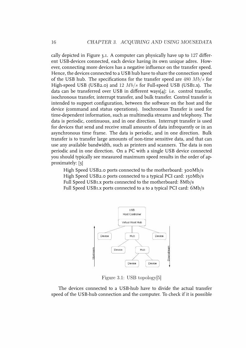
16 CHAPTER 3. ACQUIRING AND USING MOUSEDATA
cally depicted in Figure 3.1. A computer can physically have up to 127 differ-ent USB-devices connected, each device having its own unique adres. How-ever, connecting more devices has a negative influence on the transfer speed.Hence, the devices connected to a USB hub have to share the connection speedof the USB hub. The specifications for the transfer speed are 480 Mb/s forHigh-speed USB (USB2.0) and 12 Mb/s for Full-speed USB (USB1.x). Thedata can be transferred over USB in different ways[4]: i.e. control transfer,isochronous transfer, interrupt transfer, and bulk transfer. Control transfer isintended to support configuration, between the software on the host and thedevice (command and status operations). Isochronous Transfer is used fortime-dependent information, such as multimedia streams and telephony. Thedata is periodic, continuous, and in one direction. Interrupt transfer is usedfor devices that send and receive small amounts of data infrequently or in anasynchronous time frame. The data is periodic, and in one direction. Bulktransfer is to transfer large amounts of non-time sensitive data, and that canuse any available bandwidth, such as printers and scanners. The data is nonperiodic and in one direction. On a PC with a single USB device connectedyou should typically see measured maximum speed results in the order of ap-proximately: [3]
High Speed USB2.0 ports connected to the motherboard: 300Mb/sHigh Speed USB2.0 ports connected to a typical PCI card: 150Mb/sFull Speed USB1.x ports connected to the motherboard: 8Mb/sFull Speed USB1.x ports connected to a to a typical PCI card: 6Mb/s
Figure 3.1: USB topology[5]
The devices connected to a USB-hub have to divide the actual transferspeed of the USB-hub connection and the computer. To check if it is possible

3.3. THE OPERATING SYSTEM 17
to connect multiple mice to a USB hub we consider the fact that: the logitechMX518 uses 16 bits/axis. This mouse has three axis X, Y and Z (scrollwheel).The data package has the format as indicated in Table 2.4. An axis that is notused still sends two bytes of data, representing 0 displacement. The axis datafollows the first 8 bits with the mousebutton data. Therefore each cycle themouse has to send 8 + (3 ∗ 16) = 56 bits. If the data is received at 1000 Hz(pollingrate 1 ms), this results in 56 kb/s. So one USB1.x port can receive theamount of data generated by 8000
56= 143 MX518 gaming mice connected to
the motherboard, or 107 MX518 gaming mice connected to a USB port on aPCI card. This concludes that the USB connection is fast enough to connectmultiple mice as contactless measuring device.
3.3 The operating system
The data received by the computer has to be collected and processed insteadof being used for moving the mousepointer on the screen. The way the com-puter should handle data from a connected device is stated in the device driver.The device driver is a computerprogram that runs on the background to makeuse of the device possible. To be able to collect and process the mouse data thedevice driver for the mouse (mousedriver) has to be adjusted to make the dataavailable in an useable form. The logitech MX518 gaming mouse includes acd-rom with the mousedriver for Windows XP and software for a graphicaluser interface. This software can be used for adjusting the mouse sensitiv-ity and acceleration and for assigning functions to the mousebuttons. Thisdriver is a compiled computer program, and the actual computer program,the source code, is not available due to copyright restrictions. Without thesource code it is impossible to adjust the mousedriver on a Windows com-puter. The operating system Windows also has strict copyright restrictions, sothe Windows source code is also unavailable. Therefore a different operatingsystem with available sourcecode has been chosen to control the computer.This open source operating system is Linux. Linux is available in differentdistributions. Each distribution is based on the same Linux Kernel and is ac-companied by a selection of programs. The distributions differ in the selectedprograms and available tools that are included. Also the way some commandshave to be given differ slightly. The source code of linux is programmed usingthe programming language C.
The chosen Linux distribution is the Knoppix 4.0 DVD. This is a linuxdistribution that can directly run from cd or dvd. This cd or dvd version canalso be installed on a local harddrive of the computer. This is a quick and easyway to get Linux as operating system on the computer. A local harddrive install

18 CHAPTER 3. ACQUIRING AND USING MOUSEDATA
is needed to be able to adjust the mouse driver and recompile this driver.Figure 3.2 shows the dependencies among USBmodules in a linux operat-
ing system. The linux kernel is the basis of the operating system. The kernelcommunication with a USB device makes use of two separate modules: Theusbcore module and the input module. The usbcore module contains the soft-ware for hardware handling, the communication with the mouse. The hard-ware functionality is registered in the usbcore’s data structures by the hostcontroller device driver. USB has three host controller device drivers:
• OHCI the Open Host Controller Interfacerefers to the USB-1.0-specification.
• UHCI the Universal Host Controller Interfacerefers to the USB-1.1-specification.
• EHCI the Enhanced Host Controller Interfacerefers to the USB-2.0-interface.
Figure 3.2 is based on the UHCI controller, the host controller depends onwhich controller the connected device supports. Therefore OHCI and EHCIwill use the corresponding object files usb-ohci.o and usb-ehci.o to get thecorrect data structures.
The usbcore module collects data from the wire using the usb host con-troller device driver and sends it to the drive-specific drivers, the object filesusbmouse.o and usbkbd.o. The drive-specific drivers usbmouse and usbkbdread this data and send it to its final destination: the generic input handlers.The generic input handler objectfiles mousedev.o and usbkbd.o consume thedata. Hence, the object files usbmouse.o and usbkbd.o form the connectionbetween the usbcore.o module and the input.o module. Mousedev.o andkeybdev.o are generic input handlers that finally consume the data.
To measure the mouse movement, the standerd usbmouse device driverhas to be adjusted to make the mousedata available for a program that countsthe increments received from the mouse. In the TechUnited project, develop-ing a soccer playing robot, mice have already been used to measure displace-ment and detect lines on the surface. This adjusted driver is used as basis forthis traineeship. In Section 3.4 a short manual is described on how to get thismousedriver functional. This starts with the harddisk install of the knoppix4.0 DVD.
3.4 Linux setup
In this Section is described how the computer has to be setup to be able to getmeasurement data from a connected logitech MX518 gaming mouse. There-

3.4. LINUX SETUP 19
Figure 3.2: Dependencies among USB modules[11]
fore this section can be used as manual for the linux setup. Section3.6 is thesetup manual for the mouse resolution adjusting program.
3.4.1 Knoppix installation options
Knoppix running from DVD
Some extra options to be able to get a functional Knoppix 4.0 DVD version onthe student laptop NEC Versa pro 550 are described here. The Knoppix 4.0DVD can be downloaded from http://www.knoppix.org/. The additionaloptions are needed because the system would stop on the search for the properpcmcia cardmanager and the screen resolution is also corrected so the entirescreen can be used. This is realized by giving the following options afterboot: knoppix nopcmcia screen=1400x1050 depth=32Other boot options can be seen by pressing F2 or F3.
Knoppix harddisk install
Making a harddisk install of Knoppix 4.0 is described here. Knoppix 4.0 isa special version of Linux which is based on the Linux distribution Debianwith kernel 2.6.12. This version starts automatically with KDE. KDE is oneof the window managers of X-windows, the graphical user interface of Linux.Assuming Knoppix will be installed next to an existing Windows installation,there must be a separate partition on the harddisk for Linux.
If the entire disc is in use by Windows, the administrator can split up awindows partition by using a partition program like Partition Magic. Thisprogram should keep the existing data intact on the smaller partition. Alter-natives for Partition Magic are Dos or Linux Fdisk, which can be used in thecommand prompt. However these programs divide an existing partition into

20 CHAPTER 3. ACQUIRING AND USING MOUSEDATA
one or numerous new partitions which cause data loss of all the data on theexisting partition.
For the Linux install two partitions are needed: A swap partition of max-imum 500 Mb and the native partition for the actual install. While runninglinux from the knoppix 4.0 DVD, open a console window or console screen(The console is a text environment like Dos). The console window or screenshows the command line: knoppix@0[knoppix]$, this command line showsthe username followed by an ’at’-sign and the directory name within straightbrackets. The harddisk install starts by giving the command:sudo knoppix-installer, on the command line which results in:knoppix@0[knoppix]$ sudo knoppix-installerThe menu helps to get a harddisk install. Select2. Start installation and knoppix: Knoppix system like CDto get an install similar to the DVD or CD version. Finally a harddisk locationcan be selected for the install. Here is hda the first and hdb the second hard-disk hda1 is the first partition or Windows disk C:\, hda2 is the swap partition,hda3 the native partition for the installation or vice versa, hda4 is the secondwindows partition D:\, depending on the layout of the disk.
3.4.2 Replacing the mousedriver in the Kernel
After a harddisk install has been made, the existing usbmouse.cmouse driverhas to be replaced by an adjusted one. The file:/usr/src/linux-2.6.12/drivers/usb/input/usbmouse.chas to be replaced by the modified usbmouse.c1The system has to be recom-piled to make use of the new driver that provides the measurement data and ahardware timestamp (a time value).
In the kernel configuration file /usr/src/config-2.6.12 the USB HID2
Boot Protocol driver CONFIG_USB_MOUSE=mmust be activated. The option “m”means that this driver is available as module. Other options are “y” to in-stall or “n” not to install the given driver. The boot Protocol Driver can onlybe loaded as a module, the options “y” and “m” have both the same re-sult. By using the "make menuconfig" command, this option can be selectedin a menustructure, in which all desired configuration options can be set.The USB HID option can be found in the menu: "Device Drivers --->""USB support --->" "USB HID Boot Protocol drivers --->" The op-tion can be set by activating USB HIDBP Mouse (simple Boot) support.
1The usbmouse.c file is obtained from P. van den Bosch, Océ employee and a memberof the TechUnited project. In this project he used the chipset of the Logitech MX518mouse as sensor.
2Human Interface Device, (mouse, keyboard, etc.

3.5. USING MODULES 21
Leave this menu with <EXIT> and save the config file when asked.The config file now contains the configuration for the new Kernel. The
commands: "make", "make modules_install" and "make install" mustbe executed one after another in the /usr/src directory to compile the newkernel and modules.
Normally an “append string” like -version-sensor is given in menu-config because the basic kernel is adjusted to a personal version. The/boot/grub/menu.lst has to be adjusted to point to the new kernel of whichthe location is given after the compile proces. For some reason this does notresult in a working kernel. This is probably caused by the fact that the ramdiskimage /boot/initrd.img-2.6.12 is not created during the compile proces.The kernel 2.6 compile instruction as can be found on the internet did notresult in a working kernel. For this reason the kernel is compiled as describedin the previous paragraph. The /boot/grub/menu.lst does not have to bechanged because the new kernel uses the same name and directory as theprevious one.
3.5 Using modules
To be able to use a driver loaded as module, this module must be activated.A module can be activated by the user root with the command: "modprobe"followed by the name of the module, the module can be stopped with theextra command option "-r". As an example the module "ehci_hcd" is acti-vated to be able to use enhanced USB (USB2.0) with the following command:"modprobe ehci_hcd". The command "modprobe -r ehci_hcd" disablesthis module. For the Logitech MX518 gaming mouse, which uses the Uni-versal Host Controller Interface (USB1.1), this module is not required. Futuremice will be using enhanced USB (USB2.0) to be able to sendmore data faster.These mice require the activation of this module.
The existing mousedriver usbhid, used by X-windows has to be disabledand the adjusted mousedriver usbmouse has to be enabled to be able to use themouse as a measuring device. These modules are stopped and activated by thefollowing commands: "modprobe -r usbhid" and "modprobe usbmouse".The mousepointer in X-windows can still be used by a mouse connected to thePS-2 port. If an user wants to use a USB connected mouse as pointing devicethe commands "modprobe -r usbmouse" and "modprobe usbhid" restorethe original settings. Hence, the mouse can not be used as sensor with theseoriginal settings. A program possens is written to execute these commands,depending the included options on or off. With the command "possens on"the mouse can be used as a sensor and the command "possens off" the

22 CHAPTER 3. ACQUIRING AND USING MOUSEDATA
mouse returns to a normal pointing device. These commands must be exe-cuted by the user root. If the compiled program possens is saved in the follow-ing location: /usr/local/sbinmakes the program executable in every folder.The sourcecode possens.c of the program possens is listed in Appendix C.1.
3.5.1 Reading the mouse data
To be able to communicate with the adjusted usbmouse.c the device possenshas to be created. This device makes the data of the connected mice available.The device is created as root by the following command"mknod /dev/possens c 32 0". The “c” stands for a character device, 32 isthe MAJOR node, to identify the device class or group, 0 is the MINOR node,to identify a specific device. Possens is the device fromwhich another programcan collect the data generated by the mouse.
The generated device possens can be tested with the command:"cat /dev/possens" This instruction returns lines of data as long as the log-itech MX518 USB mouse moves. The instruction can be aborted by pressingthe ctrl-c keystroke. Each line of data, for example: 466703824,2,1,3, con-tains the following items: timestamp 466703824, mousenumber 2, δx−dis-placement 1 and δy−displacement 3, divided by commas. The timestampis a hardware timestamp in microseconds, which shows the time the mousedata was received and can be used to calculate speed and acceleration of themouse. The mousenumber specifies the mouse of which data is displayed,the driver supports up to four mice. The displacement data δx and δy containthe number of increments the mouse has moved in x or y direction, since thelast data was received. The "cat /dev/possens" output depends on how theusbmouse.c file defines its output, using the printf statement. The outputand its format are defined on programline 133 of usbmouse.c:
printf(string+strlen(string), "%u,%s,%d,%d\n",timestamp, mouse->usbdev->devpath, mouse->dx, mouse->dy);
The data argument %u gives the timestamp as an unsigned decimal character.The data argument %s gives the mousenumber as a string of non white char-acters. The data argument %d gives either the δx or the δy data as a decimalinteger. As can be seen these data argument types are separated by commas.The δx and δy displacement data has to be processed for both directions xand y of each mouse. A program programmed in C-code can read the for-matted input with the sscanf statement. The data is read with the followingprogramline:
sscanf( md_line, "%u,%s,%d,%d", ×tamp, mouseno, &dx, &dy);

3.6. ADJUSTING THE MOUSE RESOLUTION 23
The data is read as string md_line. The format of the string is an unsigneddecimal character, a character string and the two decimal integers, divided bycommas. The format is followed by the corresponding names for each dataargument. Integers need an adres operator because they are variable param-eters. Because the data argument %s reads the character string until it en-counters a white space or an end of line, only the first two data argumentsread a value. Reading the line of data from the previous example, the param-eters get the following values: timestamp = 466703824 mouseno = 2,1,3dx = 0 and dy = 0 The timestamp is read correctly, but the mouse numberalso reads the displacement.
It is not possible to read the mouse number as a single character withthe data argument %c because this depends on the output. In the programusbmouse.c the mouse number is defined as a character string, and is there-fore read until a white space. The easiest solution is to insert spaces betweenthe data arguments, replacing each comma in the output of usbmouse.c toenable another program to read each item seperately. Line 133 of usbmouse.cthen becomes:
sprintf(string+strlen(string), "%u %s %d %d\n",timestamp, mouse->usbdev->devpath, mouse->dx, mouse->dy);
The adapted usbmouse.c file has to replace the present version and the systemkernel has to be recompiled, as described in Section 3.4.2. After compiling theoutput of "cat /dev/possens" becomes 466703824 2 1 3.
The measurement returns the number of increments the mouse countsduring a displacement. The number of counts the mouse generates if themouse moves one inch, depends on the resolution settings. Using the 400 cpisetting a movement of one inch results in 400 increments while the samemovement results in 1600 increments if the resolution is set to 1600 cpi. Totranslate the counted increments to an actual measurement the resolution set-ting of the mouse must be available to the measurment program.
3.6 Adjusting the mouse resolution
The standard Linux mouse resolution setting of the Logitech MX518 gamingmouse after plugging in or at startup is 800 cpi. The resolution setting ofthe Logitech MX518 gaming mouse can be changed, possible settings are:400 cpi, 800 cpi, 1200 cpi and 1600 cpi. The resolution can be adjusted byhardware with two little buttons, above and below the scrollwheel on top ofthe mouse, to increase and decrease the resolution settings respectively. Theresolution can also be adjusted by software with the application LMCTL[2]

24 CHAPTER 3. ACQUIRING AND USING MOUSEDATA
Logitech Mouse control, which supports vendor-specific commands to con-trol Logitech USB mice. This application is used to receive and set the res-olution settings of the connected mice. This program was written for micethat could switch between either 400 or 800 cpi. The program must be ad-justed to recognize the Logitech MX518 and to make resolution setting avail-able for these mice. The LMCTL-0.3.1 program is available as the compressedarchive lmctl_0.3.1.tar.gz[2]. The archive file extracts to the lmctl-0.3.1folder, the extracted subfolder src contains the source code of the programfiles. The possible settings of supported mice and the connection with theUSB mouse are set in the lmctl.c file. The program cmdline.c containsthe user interface which handles the given commands, and has to be able toread and set all possible resolution settings. The LMCTL application uses aconfigure file which simplifies installation. The following commands installLMCTL: "./configure --prefix=/usr" "make" "make install", duringthis install the files in subfolder src are recompiled.
In Appendix B.1 the Logitech MX518 is added to the list of supported mice,with the variable resolution support enabled. The identifier 0xc01e was readby scanning for supported mice with the command "lmctl -s". The resolu-tion settings for 400 and 800 cpi are 3 and 4. The resolution settings 1200 and1600 cpi as proceeding steps logically result in 5 and 6. In Appendix B.2 thenew resolutions must be available for selection. The command "lmctl -8"sets the resolution to 800 cpi by reading the single character 8. The command"lmctl -12" results in an error. Reading a single character reads only thefirst character 1, the option -1 is a channel setting for wireless devices. Be-cause the Logitech MX518 has no wireless status, this option has an error asresult. Therefore there is a new option -r introduced to select resolution set-ting. The option -rmust be followed by the desired resolution. The followingoptions for LMCTL can be used:
LMCTL -Option Result"lmctl -s" Scan supported mice"lmctl -i" Inquire resolution setting"lmctl -4" or "lmctl --400" Set the resolution to 400 cpi"lmctl -8" or "lmctl --800" Set the resolution to 800 cpi"lmctl -r 4" or "lmctl -r 400" Set the resolution to 400 cpi"lmctl -r 8" or "lmctl -r 800" Set the resolution to 800 cpi"lmctl -r 12" or "lmctl -r 1200" Set the resolution to 1200 cpi"lmctl -r 16" or "lmctl -r 1600" Set the resolution to 1600 cpi

Chapter 4
Programming
The device /dev/possens makes the mouse data accessible. A program toreceive data from the device is written in the C programming language[1], tocollect this data. The program has to be able to count the movement data sep-arately for both (±x and ±y) directions of every mouse. The movement datais received in increments. The number of counts per inch (cpi) depends onthe resolution setting of each mouse. To obtain a displacement measurement,in millimeters the total number of counts in one direction divided by the reso-lution of the mouse results in a displacement in inches. The displacement ininches multiplied by 25.4 gives the displacement in millimeters for this direc-tion. The device possens also adds a timestamp to the data. The timestampis the timevalue in microseconds at which the data was received by the com-puter. The timestamp of the first measurement subtracted from a timestampreceived during the measurement, yields the elapsed time since the start ofthe measurement. Because the values of displacement and time are registeredsince the start of the measurement, average speed and acceleration can becalculated from these values.
4.1 Accuracy
How accurate is a mouse. To get an idea of the accuracy of the mouse, it has tobe calibrated. For example if the mouse is moved 10 inch (254 mm) in eitherx or y−direction this has to result in a total of 10 × RES counts, with RESthe resolution setting in cpi. If the total number of counts differs each time,this could be the result of a repeating error. To eliminate a repeating error, acorrection factor can be calculated, to correct the measurement of the mousesensor in that direction. To be able to do this, the mouse has to be displacedfor example exactly 254.0 mm (10 inch). The measurement used to calibrate
25

26 CHAPTER 4. PROGRAMMING
should be repeated at least 10 times to eliminate possible measurement errors.An average value of all measurement results is more trustworthy than thevalue of a single measurement.
In case the mouse sensor axes are oriented different than the axes of thesurface to be measured, the movement data in x− and y−direction do not cor-respond with the real movement in x− and y−direction, as shown in Figure4.1. If a movement along the x−axis of the surface, results in both displace-mentmeasurement on the x−axis and on the y−axis of themouse sensor. Themeasured displacement of the movement along the y−axis of the mouse sen-sor is caused because the axis of the mouse sensor are placed skew on the axisof the surface (skewness). With the aid of simple goniometry the skewnesscan be determined. If the degree of skewness is calculated the measured dis-placement on the mouse axes can be mapped to the real displacement on thesurface. Because the paper in the paperpath moves only forward or backwardalong one single axis, the skewness can be corrected by using the Pythagorastheorem. The hypotenuse is the displacement of the surface and the mea-sured displacement on the x− and y−axis of the mouse sensor are the sidesthat form the right-angle. To determine if the direction of the displacementwas forward or backward, the hypotenuse gets the same direction (positive ornegative) as the longest side adjacent to the right-angle.
Figure 4.1: Surface axes skew on mouse sensor axes
4.2 The measurement programs design
In this section some important issues are mentioned which determined thedesign of the measurement program. Appendix C lists the source code of allthe programs needed to be able to measure with the Logitech MX518 gaming

4.2. THE MEASUREMENT PROGRAMS DESIGN 27
mouse.The data of the device possens is read by the program lines at the end
of this paragraph. It starts with the pointer md which points to the readabledevice. Next the variables and its data types are declared. Finally, a whileloop is started which reads lines of data from the device md using the fgetsfunction. As long as fgets returns data, character strings are generated as linescontaining data. Each line of data is put in the character string md_line. Thefunction sscanf reads the formatted input of each string and separates thedata into the corresponding variables.
FILE *md;md = fopen( "/dev/possens", "r");if ( ! md ) printf(" Error opening file /dev/possens\n");
char md_line[MAXLINE];char mouseno[2];unsigned int timestamp;signed int dx;signed int dy;
while (fgets(md_line, MAXLINE, md) !=NULL){sscanf (md_line, "%u %s %d %d", ×tamp, mouseno, &dx, &dy);}
The math package must be included to be able to use mathematical func-tions like square root. To be able to compile the source code of calibrate.cand measure.c, the compiler needs the option -lm to be able to use the mathpackage math.h. The source calibrate.c and measure.c must be com-piled as follows: gcc calibrate.c -o calibrate -lm and gcc measure.c-o measure -lm to create the programs calibrate and measure.
To get correct results from a division, it is important to use the correct datatypes. Hence, an integer must be set to floating integer before it is divided orthe resulting floating integer is incorrect.
The program continuously adds or subtracts the received counts permouse.Eachmouse has a total x−displacement count (xtot) and a total y−displacementcount (ytot). The displacement is calculated from these totals each time theuser presses or releases a mousebutton. In case a mousebutton is pressed orreleased, the mouse returns a response with a zero displacement. This factis used in the calibrate program to end the calibration of that mouse. In themeasure program, this is used to let the user decide when a measurementhas to be made. The measurement data is printed on screen and saved tothe file measure.dat. This file is opened and closed each time data has to beadded, else the file would not be closed if the program is terminated using the

28 CHAPTER 4. PROGRAMMING
keystroke "ctrl-c". Without closing, no usable data can be obtained from thefile measure.dat.
A 32 bits signed integer has a maximum value of ±2, 147, 483, 647. Aninteger exceeding this value returns NI, short for Non Integer. Because thePythagoras theorem is used to calculate the displacement. The square of thetotal number of counts in x− and y−direction may not exceed this maximumvalue. Hence, the total number of counts in x−direction and y−direction maynot exceed
√2, 147, 483, 647 = 46, 340.95 ≈ 46, 341 counts. If the resolu-
tion is set to 1600 countsperinch the mouse can only measure a movement of735.7 mm (28.96 inch). This is not a problem in the program calibration,but it would be a limitation for the program measure. In the program measure,the total counts in x−direction and y−direction are divided by the resolutionsetting before they are raised to the square. The maximum movement be-comes 1177060.13 mm (1.177 km 46340.95 inch).
To be able to read data from or write data to a file, this file must be openedusing the following program lines:
FILE *f;f=fopen("filename", "option");
The option r (read) makes the file read only. The option w (write) opens afile for writing and the existing contents is lost. The option a (append) opensa file to write to, and new data is added to the existing contents. The file isclosed and the contents of a file with the write or append option is saved bythe program line: fclose(f);.
The entire program is programmed in C programming language[1] andit would be far fetched to describe the programs of Appendix C completely;more comments are included in the source files.
4.3 Using the measurement program
The user starts the measurement with the command "startchoice". Thisprogram asks the user if the mouse has to be calibrated and which resolutionthe mouse should use. It also gives the system commands and commandoptions to start the measurement with or without calibration with the desiredresolution. The source of this program is listed in Appendix C.2.
If calibration was selected, the program calibrate.c, of which the sourcecode is listed in Appendix C.3, is started. The user is asked how many micewill be calibrated, to move a desired mouse, and to push a mousebutton ofthis mouse when finished. The total number of counts on the x− and y−axisof the mouse sensor, and the derived number of counts on the hypotenuse are

4.4. MEASUREMENT RESULTS 29
listed. The next line lists the surface displacement in millimeters which is thenumber of counts on the hypotenuse divided by the resolution setting of themouse. The user is asked to give the actual displacement. The program calcu-lates a new correcting factor. The program gives the user three options: use thenew, the former, or no correction factor. The correction factor of each mouseis saved to a data file. Each resolution has its own datafile, i.e. cal_4.dat,cal_8.dat, cal_12.dat and cal_16.dat.
The measurement program measure.c, which source code is listed inAppendix C.4, is started. This program lists the data received by the device/dev/possens. Each time a mousebutton is pressed or released, the programreturns measurement data. The measurement data contains on each line thetime in seconds since the first data was received of the device /dev/possens,and the displacement in millimeters of each mouse since the start of the pro-gram measure. The measurement data is printed on screen and each line issaved in the file measure.dat for further analysis. The mouse continuousmeasuring until the keystroke "ctrl-c" is given, to terminate the program.
4.4 Measurement results
Twomice have been used tomeasure the length of an A4 paper sheet (297 mm).The mice are moved forward and backward along a guidance to guarantee adisplacement in only one direction. The guidance has a groove that lies di-rectly beneath the lens of the optical mice. If the mouse is displaced overthe guidance no displacement can be measured because the surface lies morethan 2.5 mm beneath the lens. An A4 paper sheet is placed upon this guid-ance, if the mice move along the guidance they also move directly over the A4paper sheet. This ensures the mouse can only measure a displacement whilemoving over the A4 paper sheet.
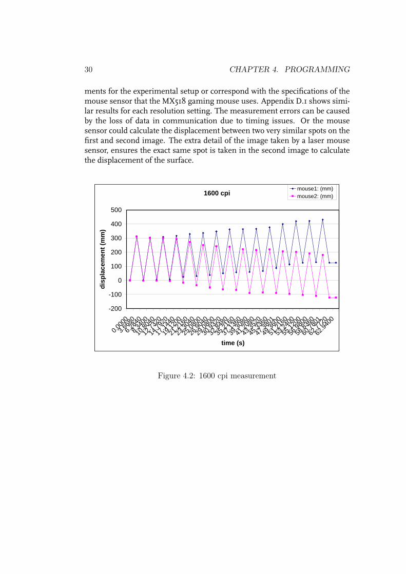
The measurements are taken with correction factor set to 1 so the data inthe measure.dat file is not corrected in any way, the contents of this file isincluded in Appendix D. As an example the measurement data at 1600 cpiis plotted as a graph in Figure 4.2. Appendix D.1 shows the analyzed mea-surements for each resolution, the measured length of the A4 paper sheet iscalculated for forward, and backward movement of the mouse, and plotted asbars as Figure 4.3 shows for this example. The average, maximum, minimumand standard deviation is determined of the forward, backward and absolutepaper length values as shown in Table 4.1 for the example. The results show adifference between the two mice. Mouse one is more accurate in forward dis-placement and mouse two is more accurate in backward displacement. Alsothe standard deviation (σ) is almost 7 mm. This does not meet the require-
30 CHAPTER 4. PROGRAMMING
ments for the experimental setup or correspond with the specifications of themouse sensor that the MX518 gaming mouse uses. Appendix D.1 shows simi-lar results for each resolution setting. The measurement errors can be causedby the loss of data in communication due to timing issues. Or the mousesensor could calculate the displacement between two very similar spots on thefirst and second image. The extra detail of the image taken by a laser mousesensor, ensures the exact same spot is taken in the second image to calculatethe displacement of the surface.
1600 cpi
-200
-100
0
100
200
300
400
500
0.000
0
3.668
0
6.284
0
8.340
0
10.80
40
12.73
20
14.79
20
17.14
40
19.12
00
21.21
60
23.30
40
25.08
00
26.90
40
29.08
00
30.93
20
32.84
80
35.21
60
37.13
60
39.30
80
41.20
80
43.35
20
45.33
60
47.38
01
49.36
00
51.21
60
53.24
00
55.12
00
56.98
00
58.83
60
60.78
01
62.77
20
62.94
00
time (s)
disp
lace
men
t (m
m)
mouse1: (mm) mouse2: (mm)
Figure 4.2: 1600 cpi measurement

4.4. MEASUREMENT RESULTS 31
-400
-300
-200
-100
0
100
200
300
400
1 3 5 7 9 11 13 15 17 19 21 23 25 27 29 31
mouse1: (mm) mouse2: (mm)
Figure 4.3: 1600 cpi δmouse measurement
Table 4.1: Measure results 1600 cpiδ mouse1: δ mouse2:
(mm) (mm)forward backward abs forward backward absolute
maximum 311.63 -285.94 311.63 309.42 -300.40 311.19average 306.39 -298.05 302.22 296.95 -305.12 301.03
minimum 297.22 -310.84 285.94 285.72 -311.19 285.72
maximum - average 5.24 12.11 9.41 12.47 4.72 10.16average - minimum 9.17 12.79 16.28 11.23 6.07 15.31
standard deviation 4.211 6.386 6.827 7.002 3.555 6.894

32 CHAPTER 4. PROGRAMMING

Chapter 5
Conclusions & Recommendations
5.1 Conclusion
This report shows that it is possible to use an optical mouse as a lowcostcontactless displacementsensor for sheet motion. The Logitech MX518 gam-ing mouse however does not meet the requirements for the use in the ex-perimental setup as shown by the measurements. The resolution settings ofthe connected mice can be set by software or mousebuttons. The optimumpollingrate for the device is determined on connection. And this report can beused as a manual to install Linux and adjust it to be able to receive measure-ment data from the Logitech MX518 gaming mouse. Hence, the data can bemade available in almost every desired format using the C Programming Lan-guage.
5.2 Recommendations
To be able to use the mouse sensor in an experimental setup, some extra studyis recommended. A study of a mouse that uses a laser could result in moreaccurate measurements because of the extra detail in the pictures processedby the mouse sensor. Beside this some other issues must be solved to be ableto make the mouse sensor a reliable displacement sensor.
To ensure accurate measurements, the mouse sensor must be calibrated.To be able to calibrate the mouse sensor, the exact movement of the mousemust be known. It would be a separate study to determine the exact movementof the mouse. A possible solution would be to use a measuring device to verifythe displacement of the mouse on the surface.
To be able to use the mouse as a motion sensor in a control loop, the con-troller must be able to receive the displacement data. The experimental setup
33
34 CHAPTER 5. CONCLUSIONS & RECOMMENDATIONS
of a printer paperpath model uses the program Matlab Simulink as a rapidprototyping environment. Therefore it would be useful to study the real timedata import of the measurement data generated by the mouse sensor.
If the mouse sensor is to be used to measure more than one direction, theprogram has to be adjusted to determine the skewness between the surfaceaxis and the axis of the mouse sensor. The degree of skewness is needed tocalculate the surface displacement in x−direction and y−direction. If needed,this displacement has to be corrected with a correction factor in x−directionand y−direction.

Bibliography
[1] Dennis M. Ritchie Brian W. Kernighan. THE C PROGRAMMING LAN-GUAGE. Number ISBN 0-13-110362-8. PRENTICE HALL, EnglewoodCliffs, New Jersey, second edition edition, 1988.
[2] Alexios Chouchoulas. Control logitech usb mice.http://www.bedroomlan.org/~alexios/coding_lmctl.html , July2004.
[3] Online. Passmark usb2.0 loop back plug faq.http://www.passmark.com/support/usb2loopback_faq.htm .
[4] Online. Usb data transfer types.http://www.jungo.com/support/documentation/windriver/811/wdusb_man_mhtml/node28.html .
[5] Online. Usb topology tree. http://it.linux-usb.org/linux.conf.au.02/talk/html/slide_4.html .
[6] Online. Document #: 38-08022 rev. *b.http://www.cypress.com/portal/server.pt/gateway/PTARGS_0_2_1524_209_259_43/http%3B/sjapp20%3B7001/publishedcontent//publish/design_resources/datasheets/contents/cy7c637xx_5.pdf , 2004.
[7] Online. Adns-3080 data sheet. http://www.avagotech.com/pc/downloadDocument.do?id=5092 , June 2005.
[8] Online. Mouse sensors. http://www.avagotech.com/products/category-detail.jsp?navId=H0,C1,C5231,C5233,C4939 , June 2005. Productsearch, or select sensor type in tree, (to get all details select data sheet inthe documents and downloads part).
[9] Online. Logitech website. http://www.logitech.com , Februari 2006.
[10] Richard L. Owens. Optical mouse technology.http://www.ida.net/users/oe1k/OpticalMouse/ , February 2006.
35

36 BIBLIOGRAPHY
[11] Alessandro Rubini. Usb device drivers.http://www.linux.it/~rubini/docs/usb/ (Reprint of Linux Maga-zine).

Appendix A
Specifications Logitech gamingmouse MX518[9]
37

38 APPENDIX A. SPECS MX518
Table A.1: Specifications Logitech gaming mouse MX518TrackingResolution 1600 cpiImage processing 5.8 megapixel/sMaximum acceleration 15 gMaximum speed 1 m/s (40"/s)
ResponsivenessUSB Data Format 16 bit/axisUSB Report Rate 125/s*USB Througput 8000 bits/sSleep mode No
GlideStatic Coefficient of friction (µs) 0.23**Dynamic Coefficient of friction (µk) 0.13**Total Weight 106 gCord 15 g
DurabillityButton life (clicks) 8 millionFeet 250 km
ComponentsMousesensor Avagotech (Agilent)[7]
ADNS3080Microcontroller Cypress[6]
CY7C63743
* This is a maximum of Microsoft Windows XP** Measured on a wood veneer surface
Appendix B
LMCTL program
To be able to list the changes the linux command diff is used to compare twofiles and list the changes. The option >filename saves this list with the givenfilename instead of displaying it on the screen. The following commands wereused:
"diff lmctl_old.c lmctl_new.c >diff_lmctl.txt""diff cmdline_old.c cmdline_new.c >diff_cmdline.txt"
In the files diff_lmctl.txt and diff_cmdline.txt the differences are listed. Thelinenumber is given followed by the deleted and added program lines. Adeleted program line comes after the smaller than symbol “<”. An addedprogram line comes after the bigger than symbol “>”.
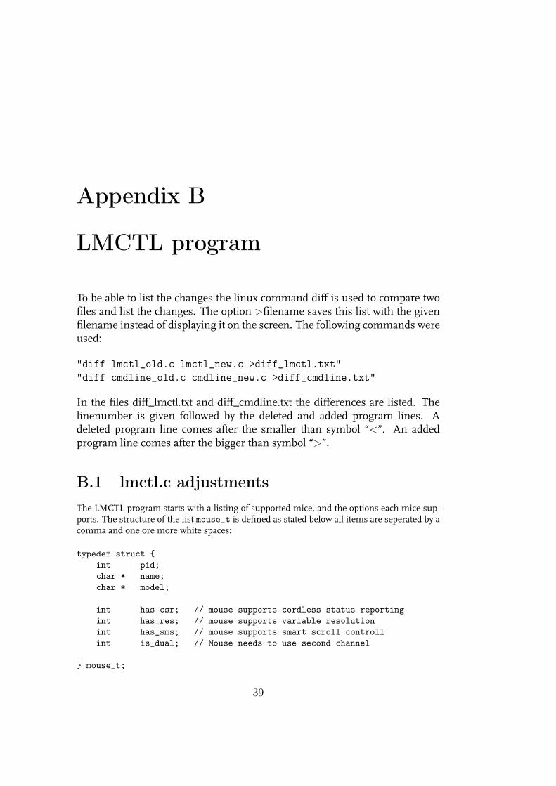
B.1 lmctl.c adjustmentsThe LMCTL program starts with a listing of supported mice, and the options each mice sup-ports. The structure of the list mouse_t is defined as stated below all items are seperated by acomma and one ore more white spaces:
typedef struct {int pid;char * name;char * model;
int has_csr; // mouse supports cordless status reportingint has_res; // mouse supports variable resolutionint has_sms; // mouse supports smart scroll controllint is_dual; // Mouse needs to use second channel
} mouse_t;
39

40 APPENDIX B. LMCTL PROGRAM
The integer “pid” is a product identifier, this contains a unique code for each type ofmice, this identifier is send by the mouse as soon as it is connected. If the list mouse_t doesnot contain the identifier the connected mouse is not supported, if it contains the number thename and model of the mouse are reported. The characters “name” and "model"contain thereported information as the identifier is recognized. The supported options are all integers,the value is “0”, if the option is not supported or “1” if the option is supported. The LogitechMX518 gaming mouse, which supports variable resolution, has to be listed as below:
{0xc01e, "MX518 Optical Mouse", "M-BS81A", 0, 1, 0, 0},Changes made to LMCTL.c The linenumbers of the original file are used. Inserted on
line 23 to 27:Revision 3.0 Januari 2006 Wiebo Kamphuis Added MX518 support, resolutions of 1200
and 1600 are now supported. Some comment was inserted for each mouse option so they areeasier recognized.
Lines 90 to 94 got the following comment:
int has_csr; // mouse supports cordless status reportingint has_res; // mouse supports variable resolutionint has_sms; // mouse supports smart scroll controllint is_dual; // Mouse needs to use second channel
Inserted on line 104:
{0xc01e, "MX518 Optical Mouse", "M-BS81A", 0, 1, 0, 0},
Replaced line:
assert ((buf [0] == 3) || (buf [0] == 4));
with:
assert ((buf [0] == 3) || (buf [0] == 4) ||(buf [0] == 5) || (buf [0] == 6));
The value buf [0] represents the resolution setting. The value 3 represents 400 cpi and 6represents 1600 cpi. The formula is ((buf [0])− 2) ∗ 400 = (setres)
Replaced line 358:
assert ((set_res == 400) || (set_res == 800));
with:
assert ((set_res == 400) || (set_res == 800) ||(set_res == 1200) || (set_res == 1600))

B.2. CMDLINE.C ADJUSTMENTS 41
B.2 cmdline.c adjustmentsThe cmdline.c program is used by LMCTL.c to handle the commandline options. The follow-ing changes were made to cmdline.c The linenumbers of the original file are used.
Inserted on line 61:
char * match_res = NULL;int inv_res = 0x0000;
On lines 128 and 130 a space was inserted between the value and the unit cpiInserted on line 132 is the text which list the possible command options for the lmctl
program. The text is listed if the command "lmctl --help" is given. Without an option thelmctl program refers to this command to get usage information.
{ "r", ’r’, "400", 0,"Set matching devices to a resolution of 400 cpi"},
{ "r", ’r’, "800", 0,"Set matching devices to a resolution of 800 cpi"},
{ "r", ’r’, "1200", 0,"Set matching devices to a resolution of 1200 cpi"},
{ "r", ’r’, "1600", 0,"Set matching devices to a resolution of 1600 cpi"},
Inserted on line 231 is the reading and handling of the option “r” to set the resolution.This option is possible to select a resolution of 1200 cpi and 1600 cpi. The option is read as asingle character. The options “12” and “16” would be read as the option “1” which is channelselection option for wireless mice, and therefore not supported by the MX518 gaming mouse.
case ’r’:match_res = strdup (arg);sscanf (arg, "%d", &inv_res);if ((inv_res / 100) > 0) inv_res = inv_res / 100;printf ("\tresolution key = %d\n",inv_res);
command = cmd_set;set_res = (int) (inv_res) * 100;break;

42 APPENDIX B. LMCTL PROGRAM

Appendix C
Program source
In this appendix the sourcecode is listed of al the new programs.
Appendix C.1 shows the program to turn the mouse into a measuring de-vice and back to the normal use as a pointing HID.
Appendix C.2 shows the program source for the user interface to choose ifa new calibration of the mouse is needed and which resolution will beused for measuring. All connected mice will be set to this resolution.
Appendix C.3 shows the program source for the calibration program. Themouse movement is measured until a mousebutton is pressed or re-leased. Because this gives a response from the mouse without a dis-placement. The program asks for the actual movement in a straight linefrom start to finish. A correction factor is calculated so the measureddata corresponds with the actual displacement. The correction factor issaved in a separate dat file for each resolution. (cal_4.dat, cal_8.dat,cal_12.dat and cal_16.dat)
Appendix C.4 shows the program that measures data. If a mousebuttonis pressed or released the passed time in seconds and the total move-ment of 4 mice in mm are listed. These lines are also saved in the filemeasure.dat for further analysis. This program uses the correction fac-tor from the dat-file generated by the calibrate program.
43

44 APPENDIX C. PROGRAM SOURCE
C.1 possens.cThe possens program is written to make it more easy to switch between the normal mousefunction as a pointing HID, and the use of the mouse as a measuring device.
/*************************************************************** Purpose: System function to deactivate hidmouse* driver and activate usbmouse driver.** Addition on and off as command option** Located in /usr/local/sbin makes the* program available in every folder.**************************************************************/
#include <stdio.h>#include <stdlib.h>#include <string.h>
int main(int argc, char *argv[]){if (argc == 2)
{printf("%s\n",argv[1]);
if (strcmp("on", argv[1])==0){
system("modprobe -r usbhid");system("modprobe usbmouse");
}else if (strcmp("off", argv[1])==0)
{system("modprobe -r usbmouse");system("modprobe usbhid");
}else
printf("possens on and possens off are the only valid options\n");}
else {printf("Possens needs a single option\n");printf("’Possens on’ to close usbhid and start usbmouse\n");printf("’Possens off’ to close usbmouse and start usbhid\n");}
return 0;}

C.2. STARTCHOICE.C 45
C.2 startchoice.c
/** This program is to be able to choose between calibrating each mouse* for the desired resolution and starting a measurement.*/
#include <stdio.h>#include <string.h>
int main(void){
char sel;char sel2;int ncal;int i;int res;
printf("Do you want to calibrate before starting the measurement? \t (Y)es or (N)o \n ");printf("Type Y or N followed by Enter\n ");scanf("%c", &sel);printf("\t The MX518 lasermouse supports multiple resolutions.\n ");printf("Possible resolutions are 400, 800, 1200 and 1600 counts per inch.\n ");printf("\t Type the desired resolution followed by Enter.\n ");scanf("%d", &res);
if (sel == ’Y’ || sel == ’y’) {printf("How many Logitech MX518 mice must be calibrated. The maximum is 4 mice.\n");printf("Type the number 1 - 4 followed by Enter\n");scanf("%d", &ncal);i = 1;printf("%d mice will be calibrated\n", ncal);while (i <= ncal){printf("The calibration program will be started for the selected resolution\n");
switch (res){case 400: system("calibrate 400"); break;case 800: system("calibrate 800"); break;case 1200: system("calibrate 1200"); break;case 1600: system("calibrate 1600"); break;default: printf ("The given resolution is not supported\n");};
printf("Type N followed by Enter to stop calibrating and start measurement or pressEnter to calibrate the next mouse\n ");
scanf("%c", &sel2);if (sel2 == ’N’ || sel2 == ’n’) break;i++;if (i > ncal){printf("The selected amount of %d calibrations are completed\n", ncal);

46 APPENDIX C. PROGRAM SOURCE
sel2 = ’N’;}
}}
if (sel == ’N’ || sel == ’n’) {printf("The measurement will be corrected with the data of the last
calibration.\n");switch (res){case 400: system("lmctl -r 400"); system("measure 400"); break;case 800: system("lmctl -r 800"); system("measure 800"); break;case 1200: system("lmctl -r 1200"); system("measure 1200"); break;case 1600: system("lmctl -r 1600"); system("measure 1600"); break;default: printf ("The given resolution is not supported\n");}
}
if (sel2 == ’N’ || sel2 == ’n’) {printf("The measurement will be corrected with the data of the calibration.\n");
switch (res){case 400: system("measure 400"); break;case 800: system("measure 800"); break;case 1200: system("measure 1200"); break;case 1600: system("measure 1600"); break;default: printf ("The given resolution is not supported\n");}
}
else printf("You typed a non valid option.\n");
return 0;}

C.3. CALIBRATE.C 47
C.3 calibrate.c
/*************************************************************** Purpose: Function to calibrate each mouse for every* resolution so the measurement can be adjusted* accordingly.**************************************************************/
#include <stdio.h>#include <stdlib.h>#include <string.h>#include <time.h>#include <math.h>
#define MAXLINE 25#define INPUT /dev/possens
signed int xtot1, xtot2, xtot3, xtot4;signed int ytot1, ytot2, ytot3, ytot4;float mov1, mov2, mov3, mov4;float rmov1, rmov2, rmov3, rmov4;float cfact1, cfact2, cfact3, cfact4;float oldcfact1, oldcfact2, oldcfact3, oldcfact4;int ABC;
// SUM Functionsigned int sum(signed int total, signed int delta ){
int s;s = total + delta;return s;
}
/*************************************************************** Purpose: System function to read resolution**************************************************************/
int measure(float RES){
FILE *md;char md_line[MAXLINE];int i;
signed int dx, dx1, dx2, dx3, dx4;signed int dy, dy1, dy2, dy3, dy4;

48 APPENDIX C. PROGRAM SOURCE
int mousenoi;char mouseno[2];
unsigned int timestamp;
md = fopen( "/dev/possens", "r");if ( ! md )
{printf(" Error opening file /dev/possens\n");}
i = 1;xtot1 = 0; xtot2 = 0; xtot3 = 0; xtot4 = 0;ytot1 = 0; ytot2 = 0; ytot3 = 0; ytot4 = 0;
while (fgets(md_line, MAXLINE, md) !=NULL){
sscanf (md_line, "%u %s %d %d", ×tamp, mouseno, &dx, &dy);
mousenoi = atoi(mouseno);
printf("time = %u mousenumber = %d position dx = %d dy = %d \n",timestamp, mousenoi, dx, dy);
switch (mousenoi){case 1: xtot1 = sum(xtot1, dx); ytot1 = sum(ytot1, dy); break;case 2: xtot2 = sum(xtot2, dx); ytot2 = sum(ytot2, dy); break;case 3: xtot3 = sum(xtot3, dx); ytot3 = sum(ytot3, dy); break;case 4: xtot4 = sum(xtot4, dx); ytot4 = sum(ytot4, dy); break;default: printf ("No mouse connected\n");}
if (dx == 0 && dy == 0) break;}return mousenoi;
}
int main(int argc, char *argv[]){float RES;
printf("\n\n\t Move mouse or surface the desired x direction and push one of itsmousebuttons when finished.\n\n\n");
FILE *f;if (argc == 2)
{printf("calibrating resolution %s\n",argv[1]);

C.3. CALIBRATE.C 49
if (strcmp("400", argv[1])==0){
system("lmctl -r 400");RES = 400;f=fopen("cal_4.dat", "r");
fscanf(f,"%*s %f %*s %f %*s %f %*s %f",&oldcfact1, &oldcfact2, &oldcfact3, &oldcfact4);
fclose(f);f=fopen("cal_4.dat", "w");if (f == NULL) printf("No correction data available for 400 cpi\n");
}else if (strcmp("800", argv[1])==0)
{system("lmctl -r 800");RES = 800;f=fopen("cal_8.dat", "r");
fscanf(f,"%*s %f %*s %f %*s %f %*s %f",&oldcfact1, &oldcfact2, &oldcfact3, &oldcfact4);
fclose(f);f=fopen("cal_8.dat", "w");if (f == NULL) printf("No correction data available for 800 cpi\n");
}else if (strcmp("1200", argv[1])==0)
{system("lmctl -r 1200");RES = 1200;f=fopen("cal_12.dat", "r");
fscanf(f,"%*s %f %*s %f %*s %f %*s %f",&oldcfact1, &oldcfact2, &oldcfact3, &oldcfact4);
fclose(f);f=fopen("cal_12.dat", "w");if (f == NULL) printf("No correction data available for 1200 cpi\n");
}else if (strcmp("1600", argv[1])==0)
{system("lmctl -r 1600");RES = 1600;f=fopen("cal_16.dat", "r");
fscanf(f,"%*s %f %*s %f %*s %f %*s %f",&oldcfact1, &oldcfact2, &oldcfact3, &oldcfact4);
fclose(f);f=fopen("cal_16.dat", "w");if (f == NULL) printf("No correction data available for 1600 cpi\n");
}else
printf("400, 800, 1200 and 1600 are the only options of cal.\n");}

50 APPENDIX C. PROGRAM SOURCE
else {printf("calibrate needs the resolution as a single option\n");printf("’calibrate 400, calibrate 800, calibrate 1200 or calibrate 1600.\n");}
int mouseno = measure(RES);float mm_pc = 25.4 / RES;
/* printf("mouse1: %f mouse2: %f mouse3: %f mouse4: %f Resolution: %.0f countsper inch\n",
oldcfact1, oldcfact2, oldcfact3, oldcfact4, RES);*/
/* Pythagoras theorem */
mov1 = sqrt((xtot1*xtot1)+(ytot1*ytot1));mov2 = sqrt((xtot2*xtot2)+(ytot2*ytot2));mov3 = sqrt((xtot3*xtot3)+(ytot3*ytot3));mov4 = sqrt((xtot4*xtot4)+(ytot4*ytot4));
/* One main direction determines if the direction is positive or negative.* In one dimensional measurement the measurement in the perpendicular
irection is caused by misalignment. */
if (fabs(xtot1) > fabs(ytot1) && xtot1 < 0) mov1 = -mov1;if (fabs(xtot1) < fabs(ytot1) && ytot1 < 0) mov1 = -mov1;if (fabs(xtot2) > fabs(ytot2) && xtot2 < 0) mov2 = -mov2;if (fabs(xtot2) < fabs(ytot2) && ytot2 < 0) mov2 = -mov2;if (fabs(xtot3) > fabs(ytot3) && xtot3 < 0) mov3 = -mov3;if (fabs(xtot3) < fabs(ytot3) && ytot3 < 0) mov3 = -mov3;if (fabs(xtot4) > fabs(ytot4) && xtot4 < 0) mov4 = -mov4;if (fabs(xtot4) < fabs(ytot4) && ytot4 < 0) mov4 = -mov4;
if (xtot1 != 0 && ytot1 != 0){printf("end calibration mouse 1: xtot1= %d and ytot1= %d gives: %.2f\n",
xtot1, ytot1, mov1);printf("mouse 1 moved %.3f mm. Give the real displacement in mm and press Enter\n",
mov1*mm_pc);scanf("%f", &rmov1);cfact1 = rmov1/(mov1*mm_pc);cfact2 = oldcfact2;cfact3 = oldcfact3;cfact4 = oldcfact4;printf("\tThis results to a correction factor of %.3f\n", cfact1);printf("Give your selection followed by Enter\n\t\t 1: to use the new correction
factor %.3f\n", cfact1);printf("\t\t 2: to use the former correction factor %.3f\n\t\t 3: to use no
correction factor\n", oldcfact1);scanf("%d", &ABC);switch(ABC){
case 1: oldcfact1 = cfact1; printf("\tThe measurements of mouse 1 will be

C.3. CALIBRATE.C 51
corrected by factor %.3f\n", cfact1); break;case 2: cfact1 = oldcfact1; printf("\tThe measurements of mouse 1 will be
corrected by factor %.3f\n", cfact1); break;case 3: cfact1 = 1; oldcfact1 = 1; printf("\tThe measurements of mouse 1 will
be corrected by factor %.3f\n", cfact1); break;default: printf ("a non valid option is given\n") ;}
}
if (xtot2 != 0 && ytot2 != 0){printf("end calibration mouse 2: xtot2= %d and ytot2= %d gives: %.2f\n",
xtot2, ytot2, mov2);printf("mouse 2 moved %.3f mm. Give the real displacement in mm and press Enter\n",
mov2*mm_pc);scanf("%f", &rmov2);cfact2 = rmov2/(mov2*mm_pc);cfact1 = oldcfact1;cfact3 = oldcfact3;cfact4 = oldcfact4;printf("\tThis results to a correction factor of %.3f\n", cfact2);printf("Give your selection followed by Enter\n\t\t 1: to use the new correction
factor %.3f\n", cfact2);printf("\t\t 2: to use the former correction factor %.3f\n\t\t 3: to use no
correction factor\n", oldcfact2);scanf("%d", &ABC);switch(ABC){
case 1: oldcfact2 = cfact2; printf("\tThe measurements of mouse 2 will be correctedby factor %.3f\n", cfact2); break;
case 2: cfact2 = oldcfact2; printf("\tThe measurements of mouse 2 will be correctedby factor %.3f\n", cfact2); break;
case 3: cfact2 = 1; oldcfact2 = 1; printf("\tThe measurements of mouse 2 will becorrected by factor %.3f\n", cfact2); break;
default: printf ("a non valid option is given\n") ;}
}
if (xtot3 != 0 && ytot3 != 0){printf("end calibration mouse 3: xtot3= %d and ytot3= %d gives: %.2f\n",
xtot3, ytot3, mov3);printf("mouse 3 moved %.3f mm. Give the real displacement in mm and press
Enter\n", mov3*mm_pc);scanf("%f", &rmov3);cfact3 = rmov3/(mov3*mm_pc);cfact1 = oldcfact1;cfact2 = oldcfact2;cfact4 = oldcfact4;printf("\tThis results to a correction factor of %.3f\n", cfact1);printf("Give your selection followed by Enter\n\t\t 1: to use the new correction
factor %.3f\n", cfact3);

52 APPENDIX C. PROGRAM SOURCE
printf("\t\t 2: to use the former correction factor %.3f\n\t\t 3: to use nocorrection factor\n", oldcfact3);
scanf("%d", &ABC);switch(ABC){
case 1: oldcfact3 = cfact3; printf("\tThe measurements of mouse 3 will becorrected by factor %.3f\n", cfact3); break;
case 2: cfact3 = oldcfact3; printf("\tThe measurements of mouse 3 will becorrected by factor %.3f\n", cfact3); break;
case 3: cfact3 = 1; oldcfact3 = 1; printf("\tThe measurements of mouse 3will be corrected by factor %.3f\n", cfact3); break;
default: printf ("a non valid option is given\n") ;}
}
if (xtot4 != 0 && ytot4 != 0){printf("end calibration mouse 4: xtot4= %d and ytot4= %d gives: %.2f\n",
xtot4, ytot4, mov4);printf("mouse 4 moved %.3f mm. Give the real displacement in mm and press
Enter\n", mov4*mm_pc);scanf("%f", &rmov4);cfact4 = rmov4/(mov4*mm_pc);cfact1 = oldcfact1;cfact2 = oldcfact2;cfact3 = oldcfact3;printf("\tThis results to a correction factor of %.3f\n", cfact4);printf("Give your selection followed by Enter\n\t\t 1: to use the new correction
factor %.3f\n", cfact4);printf("\t\t 2: to use the former correction factor %.3f\n\t\t 3: to use no
correction factor\n", oldcfact4);scanf("%d", &ABC);switch(ABC){
case 1: oldcfact4 = cfact4; printf("\tThe measurements of mouse 4 will becorrected by factor %.3f\n", cfact4); break;
case 2: cfact4 = oldcfact4; printf("\tThe measurements of mouse 4 will becorrected by factor %.3f\n", cfact4); break;
case 3: cfact4 = 1; oldcfact4 = 1; printf("\tThe measurements of mouse 4 willbe corrected by factor %.3f\n", cfact4); break;
default: printf ("a non valid option is given\n") ;}
}
printf("mouse1: %f mouse2: %f mouse3: %f mouse4: %f Resolution: %.0f counts perinch\n",cfact1, cfact2, cfact3, cfact4, RES);
fprintf(f,"mouse1: %f mouse2: %f mouse3: %f mouse4: %f Resolution: %.0f counts perinch\n",cfact1, cfact2, cfact3, cfact4, RES);
fclose(f);return 0;}

C.4. MEASURE.C 53
C.4 measure.c
/************************************************************** A programfile located in folder /usr/local/bin* makes this program available in every folder.*************************************************************/
/************************************************************** Purpose: Function to measure each mouse at the selected* resolution so the measurement can be adjusted* accordingly and corrected with the calibration* data for that resolution.*************************************************************/
#include <stdio.h>#include <stdlib.h>#include <string.h>#include <time.h>#include <math.h>
#define MAXLINE 25#define INPUT /dev/possens
// SUM Functionsigned int sum(signed int total, signed int delta ){
signed int s;s = total + delta;return s;
}
/* Pythagoras theorem *//* One main direction determines if the direction is positive or negative.* In one dimensional measurement the measurement in the perpendicular direction is
caused by misalignment. */
// MOV functionfloat MOV(signed int xtot, signed int ytot, float RES){
float mm_pi = 25.4;float MV;float MV_mm;float xtoti, ytoti;xtoti = xtot / RES;ytoti = ytot / RES;MV = sqrt((xtoti * xtoti)+(ytoti*ytoti));if (fabs(xtot) > fabs(ytot) && xtot < 0) MV = -MV;if (fabs(xtot) < fabs(ytot) && ytot < 0) MV = -MV;MV_mm = MV * mm_pi;return MV_mm;
}
54 APPENDIX C. PROGRAM SOURCE
/************************************************************** Purpose: System function to read resolution*************************************************************/
int main(int argc, char *argv[]){
signed int dx, dx1, dx2, dx3, dx4;signed int dy, dy1, dy2, dy3, dy4;signed int xtot1, xtot2, xtot3, xtot4;signed int ytot1, ytot2, ytot3, ytot4;float mov1, mov2, mov3, mov4;float cfact1, cfact2, cfact3, cfact4;float RES;
int mousenoi;char mouseno[2];
unsigned int timestamp;unsigned int timestamp_old;float dtime_us;float dtime_s;
printf("\n\t\t\t Push a mousebutton to receive data.\n");printf("\n\t The data received by pressing and releasing a mousebutton is saved to
the file measure.dat for further analysis.\n");printf("\n\t\t\t Press ctrl-c to stop measurement. \n");
FILE *fc;if (argc == 2)
{printf("calibrating resolution %s\n",argv[1]);
if (strcmp("400", argv[1])==0){
RES = 400;fc=fopen("cal_4.dat", "r");if (fc == NULL) printf("No correction data available for 400 cpi\n");
}else if (strcmp("800", argv[1])==0)
{RES = 800;fc=fopen("cal_8.dat", "r");if (fc == NULL) printf("No correction data available for 800 cpi\n");
}else if (strcmp("1200", argv[1])==0)
{RES = 1200;fc=fopen("cal_12.dat", "r");

C.4. MEASURE.C 55
if (fc == NULL) printf("No correction data available for 1200 cpi\n");}
else if (strcmp("1600", argv[1])==0){
RES = 1600;fc=fopen("cal_16.dat", "r");if (fc == NULL) printf("No correction data available for 1600 cpi\n");
}else
printf("400, 800, 1200 and 1600 are the only options of measure.\n");}
else {printf("measure needs the resolution as a single option\n");printf("measure 400, measure 800, measure 1200 or measure 1600.\n");}
fscanf(fc,"%*s %f %*s %f %*s %f %*s %f", &cfact1, &cfact2, &cfact3, &cfact4);fclose(fc);
/******************************************************************************* Opening file measure.dat to check if the data file is available.* With the option "w" for writable results in an empty file when closed.******************************************************************************/
FILE *fmd;fmd=fopen("measure.dat", "w");
if (fmd == NULL) {printf("The measurement-datafile measure.dat does not exist\n");return 0;}
fprintf(fmd,"time: (seconds) \tmouse1: (mm) \t\tmouse2: (mm) \t\tmouse3: (mm)\t\tmouse4: (mm) \n");
fclose(fmd);
/* actual measurement */
char md_line[MAXLINE];int i;FILE *md;md = fopen( "/dev/possens", "r");if ( ! md )
{printf(" Error opening file /dev/possens\n");}
i = 1;xtot1 = 0; xtot2 = 0; xtot3 = 0; xtot4 = 0;ytot1 = 0; ytot2 = 0; ytot3 = 0; ytot4 = 0;
while (fgets(md_line, MAXLINE, md) !=NULL)

56 APPENDIX C. PROGRAM SOURCE
{sscanf (md_line, "%u %s %d %d", ×tamp, mouseno, &dx, &dy);
mousenoi = atoi(mouseno);
printf("time = %u mousenumber = %d position dx = %d dy = %d \n",timestamp, mousenoi, dx, dy);
if (i== 1) timestamp_old = timestamp;switch (mousenoi){case 1: xtot1 = sum(xtot1, dx); ytot1 = sum(ytot1, dy); break;case 2: xtot2 = sum(xtot2, dx); ytot2 = sum(ytot2, dy); break;case 3: xtot3 = sum(xtot3, dx); ytot3 = sum(ytot3, dy); break;case 4: xtot4 = sum(xtot4, dx); ytot4 = sum(ytot4, dy); break;default: printf ("No mouse connected\n");}
/******************************************************************************* Mousebutton pressed gives mousesignal without movement.* Opening file meassure.dat with the option "a" for append* adds another line to the existing data in the file.* Without closing the file data would be lost if the measurement is* terminated with keystroke "ctrl-c".******************************************************************************/
if (dx == 0 && dy == 0) {dtime_us = (timestamp - timestamp_old);dtime_s = dtime_us / 1000000;mov1 = cfact1 * MOV(xtot1, ytot1, RES);mov2 = cfact2 * MOV(xtot2, ytot2, RES);mov3 = cfact3 * MOV(xtot3, ytot3, RES);mov4 = cfact4 * MOV(xtot4, ytot4, RES);printf("time %12.4f seconds positions mouse1: %.2f mm mouse2: %.2f mm mouse3:
%.2f mm mouse4: %.2f mm\n",dtime_s, mov1, mov2, mov3, mov4);
fmd=fopen("measure.dat", "a");fprintf(fmd,"%12.4f \t\t%12.2f \t\t%12.2f \t\t%12.2f \t\t%12.2f\n",
dtime_s, mov1, mov2, mov3, mov4);fclose(fmd);}
i++;}
return 0;}

Appendix D
Measurements
The measure.dat file after measurement at 400 cpi.
time: (seconds) mouse1: (mm) mouse2: (mm) mouse3: (mm) mouse4: (mm)0.0000 0.00 0.00 0.00 0.002.7360 310.32 305.31 0.00 0.005.1200 13.08 7.18 0.00 0.009.7000 329.18 312.55 0.00 0.00
11.8600 36.83 10.22 0.00 0.0014.5480 340.11 320.04 0.00 0.0016.3360 58.23 18.42 0.00 0.0018.1280 365.95 320.23 0.00 0.0019.8840 78.36 12.70 0.00 0.0021.7400 374.59 294.58 0.00 0.0023.4480 95.12 -7.75 0.00 0.0025.0200 392.49 278.89 0.00 0.0026.8280 89.28 -18.48 0.00 0.0028.5360 392.87 270.51 0.00 0.0030.1960 113.47 -24.51 0.00 0.0032.2640 416.62 278.19 0.00 0.0034.1520 120.78 -30.92 0.00 0.0036.3362 428.62 259.33 0.00 0.0037.9960 123.89 -42.61 0.00 0.0040.0000 435.55 238.63 0.00 0.0041.5320 153.92 -66.04 0.00 0.0043.6080 461.84 239.08 0.00 0.0045.5760 168.15 -69.21 0.00 0.0047.4240 476.44 236.66 0.00 0.0049.2440 170.50 -70.87 0.00 0.0050.9404 477.65 235.46 0.00 0.0052.7240 189.55 -68.45 0.00 0.0054.3441 493.01 233.43 0.00 0.0056.1640 208.92 -69.47 0.00 0.0057.8080 514.03 232.03 0.00 0.0059.7680 224.28 -68.01 0.00 0.0060.0360 224.28 -68.01 0.00 0.00
57

58 APPENDIX D. MEASUREMENTS
The measure.dat file after measurement at 800 cpi.
time: (seconds) mouse1: (mm) mouse2: (mm) mouse3: (mm) mouse4: (mm)0.0000 0.00 0.00 0.00 0.002.6640 307.69 304.01 0.00 0.004.8600 18.22 4.48 0.00 0.006.8080 324.39 291.56 0.00 0.008.6720 35.21 -10.45 0.00 0.00
10.5080 344.01 285.02 0.00 0.0012.5800 49.56 -20.73 0.00 0.0014.3240 362.90 278.45 0.00 0.0016.3960 66.20 -21.08 0.00 0.0018.0760 374.81 283.69 0.00 0.0020.1520 83.38 -15.75 0.00 0.0022.1480 394.11 271.43 0.00 0.0024.0440 88.14 -31.91 0.00 0.0025.8160 390.33 257.81 0.00 0.0027.9640 98.58 -53.34 0.00 0.0029.8280 403.32 251.24 0.00 0.0031.8080 102.24 -51.82 0.00 0.0033.6040 401.83 237.36 0.00 0.0035.4680 100.43 -67.60 0.00 0.0037.1760 413.00 238.38 0.00 0.0039.0440 123.99 -64.14 0.00 0.0040.7841 430.28 240.82 0.00 0.0042.7160 142.02 -64.04 0.00 0.0044.4080 446.85 237.74 0.00 0.0046.4280 142.46 -60.71 0.00 0.0048.1200 444.37 240.76 0.00 0.0050.1360 154.66 -61.56 0.00 0.0051.8360 462.50 225.90 0.00 0.0053.7120 166.12 -76.49 0.00 0.0055.3520 474.38 217.81 0.00 0.0057.2601 166.05 -90.30 0.00 0.0057.4481 166.05 -90.30 0.00 0.00

59
The measure.dat file after measurement at 1200 cpi.
time: (seconds) mouse1: (mm) mouse2: (mm) mouse3: (mm) mouse4: (mm)0.0000 0.00 0.00 0.00 0.003.3240 410.17 407.78 0.00 0.005.5480 12.34 -3.35 0.00 0.007.3680 422.70 387.65 0.00 0.009.2440 12.76 -18.83 0.00 0.00
11.0080 418.70 370.76 0.00 0.0012.6520 21.25 -39.31 0.00 0.0014.3280 429.60 338.39 0.00 0.0016.1040 42.29 -75.46 0.00 0.0017.6720 440.75 326.03 0.00 0.0019.2760 60.03 -67.95 0.00 0.0020.8280 462.36 322.28 0.00 0.0022.4200 78.34 -80.67 0.00 0.0023.9000 494.20 317.75 0.00 0.0025.6600 114.60 -85.43 0.00 0.0027.2200 525.44 306.75 0.00 0.0029.3680 121.60 -102.09 0.00 0.0031.1000 534.35 281.37 0.00 0.0033.1353 137.56 -132.61 0.00 0.0034.7440 544.55 266.19 0.00 0.0036.7160 155.22 -146.83 0.00 0.0038.5040 563.16 258.25 0.00 0.0040.4520 178.84 -153.99 0.00 0.0042.2320 592.65 230.70 0.00 0.0044.0560 187.24 -181.04 0.00 0.0045.6560 597.47 204.49 0.00 0.0047.5720 203.05 -194.25 0.00 0.0049.3520 607.14 194.52 0.00 0.0051.3200 219.16 -214.82 0.00 0.0053.0360 622.94 189.63 0.00 0.0055.1280 231.75 -221.70 0.00 0.0055.4920 231.75 -221.70 0.00 0.00

60 APPENDIX D. MEASUREMENTS
The measure.dat file after measurement at 1600 cpi.
time: (seconds) mouse1: (mm) mouse2: (mm) mouse3: (mm) mouse4: (mm)0.0000 0.00 0.00 0.00 0.003.6680 311.63 309.42 0.00 0.006.2840 0.79 -1.77 0.00 0.008.3400 301.78 301.12 0.00 0.00
10.8040 3.71 -1.64 0.00 0.0012.7320 307.71 299.45 0.00 0.0014.7920 4.84 -4.05 0.00 0.0017.1440 315.23 292.35 0.00 0.0019.1200 23.92 -16.15 0.00 0.0021.2160 328.61 272.51 0.00 0.0023.3040 30.12 -35.47 0.00 0.0025.0800 336.12 250.25 0.00 0.0026.9040 37.40 -50.96 0.00 0.0029.0800 346.74 240.91 0.00 0.0030.9320 50.58 -64.82 0.00 0.0032.8480 361.65 238.95 0.00 0.0035.2160 57.17 -67.96 0.00 0.0037.1360 362.95 221.01 0.00 0.0039.3080 59.90 -90.00 0.00 0.0041.2080 364.81 214.62 0.00 0.0043.3520 65.92 -86.96 0.00 0.0045.3360 376.30 218.59 0.00 0.0047.3801 87.46 -89.54 0.00 0.0049.3600 398.89 205.29 0.00 0.0051.2160 112.95 -95.11 0.00 0.0053.2400 419.62 201.85 0.00 0.0055.1200 124.02 -102.79 0.00 0.0056.9800 421.24 190.52 0.00 0.0058.8360 128.37 -109.91 0.00 0.0060.7801 429.67 180.27 0.00 0.0062.7720 125.00 -122.56 0.00 0.0062.9400 125.00 -122.56 0.00 0.00

D.1. ANALYZED MEASUREMENT RESULTS 61
D.1 Analyzed measurement results

62 APPENDIX D. MEASUREMENTS
Table D.1: Measure results 400 cpitime: mouse1: mouse2: δ mouse1: δ mouse2:
(seconds) (mm) (mm) (mm) (mm)0.0000 0.00 0.00 forward backward abs forward backward abs2.7360 310.32 305.31 310.32 310.32 305.31 305.315.1200 13.08 7.18 -297.24 297.24 -298.13 298.139.7000 329.18 312.55 316.10 316.1 305.37 305.37
11.8600 36.83 10.22 -292.35 292.35 -302.33 302.3314.5480 340.11 320.04 303.28 303.28 309.82 309.8216.3360 58.23 18.42 -281.88 281.88 -301.62 301.6218.1280 365.95 320.23 307.72 307.72 301.81 301.8119.8840 78.36 12.70 -287.59 287.59 -307.53 307.5321.7400 374.59 294.58 296.23 296.23 281.88 281.8823.4480 95.12 -7.75 -279.47 279.47 -302.33 302.3325.0200 392.49 278.89 297.37 297.37 286.64 286.6426.8280 89.28 -18.48 -303.21 303.21 -297.37 297.3728.5360 392.87 270.51 303.59 303.59 288.99 288.9930.1960 113.47 -24.51 -279.40 279.4 -295.02 295.0232.2640 416.62 278.19 303.15 303.15 302.70 302.734.1520 120.78 -30.92 -295.84 295.84 -309.11 309.1136.3362 428.62 259.33 307.84 307.84 290.25 290.2537.9960 123.89 -42.61 -304.73 304.73 -301.94 301.9440.0000 435.55 238.63 311.66 311.66 281.24 281.2441.5320 153.92 -66.04 -281.63 281.63 -304.67 304.6743.6080 461.84 239.08 307.92 307.92 305.12 305.1245.5760 168.15 -69.21 -293.69 293.69 -308.29 308.2947.4240 476.44 236.66 308.29 308.29 305.87 305.8749.2440 170.50 -70.87 -305.94 305.94 -307.53 307.5350.9404 477.65 235.46 307.15 307.15 306.33 306.3352.7240 189.55 -68.45 -288.10 288.1 -303.91 303.9154.3441 493.01 233.43 303.46 303.46 301.88 301.8856.1640 208.92 -69.47 -284.09 284.09 -302.90 302.957.8080 514.03 232.03 305.11 305.11 301.50 301.559.7680 224.28 -68.01 -289.75 289.75 -300.04 300.0460.0360 224.28 -68.01
maximum 316.10 -279.40 316.10 309.82 -295.02 309.82average 305.95 -290.99 298.47 298.31 -302.85 300.58
minimum 296.23 -305.94 279.40 281.24 -309.11 281.24
maximum - average 10.15 11.59 17.63 11.51 7.83 9.24average - minimum 9.72 14.95 19.07 17.07 6.26 19.34
standard deviation 4.952 8.718 10.303 9.320 4.012 7.525

D.1. ANALYZED MEASUREMENT RESULTS 63
400 cpi
-100
0
100
200
300
400
500
600
0.000
0
2.736
0
5.120
0
9.700
0
11.86
00
14.54
80
16.33
60
18.12
80
19.88
40
21.74
00
23.44
80
25.02
00
26.82
80
28.53
60
30.19
60
32.26
40
34.15
20
36.33
62
37.99
60
40.00
00
41.53
20
43.60
80
45.57
60
47.42
40
49.24
40
50.94
04
52.72
40
54.34
41
56.16
40
57.80
80
59.76
80
60.03
60
time (s)
disp
lace
men
t (m
m)
mouse1: (mm) mouse2: (mm)
Figure D.1: 400 cpi measurement
-400
-300
-200
-100
0
100
200
300
400
1 3 5 7 9 11 13 15 17 19 21 23 25 27 29 31
mouse1: (mm) mouse2: (mm)
Figure D.2: 400 cpi δmouse measurement

64 APPENDIX D. MEASUREMENTS
Table D.2: Measure results 800 cpitime: mouse1: mouse2: δ mouse1: δ mouse2:
(seconds) (mm) (mm) (mm) (mm)0.0000 0.00 0.00 forward backward abs forward backward abs2.6640 307.69 304.01 307.69 307.69 304.01 304.014.8600 18.22 4.48 -289.47 289.47 -299.53 299.536.8080 324.39 291.56 306.17 306.17 287.08 287.088.6720 35.21 -10.45 -289.18 289.18 -302.01 302.01
10.5080 344.01 285.02 308.80 308.8 295.47 295.4712.5800 49.56 -20.73 -294.45 294.45 -305.75 305.7514.3240 362.90 278.45 313.34 313.34 299.18 299.1816.3960 66.20 -21.08 -296.70 296.7 -299.53 299.5318.0760 374.81 283.69 308.61 308.61 304.77 304.7720.1520 83.38 -15.75 -291.43 291.43 -299.44 299.4422.1480 394.11 271.43 310.73 310.73 287.18 287.1824.0440 88.14 -31.91 -305.97 305.97 -303.34 303.3425.8160 390.33 257.81 302.19 302.19 289.72 289.7227.9640 98.58 -53.34 -291.75 291.75 -311.15 311.1529.8280 403.32 251.24 304.74 304.74 304.58 304.5831.8080 102.24 -51.82 -301.08 301.08 -303.06 303.0633.6040 401.83 237.36 299.59 299.59 289.18 289.1835.4680 100.43 -67.60 -301.40 301.4 -304.96 304.9637.1760 413.00 238.38 312.57 312.57 305.98 305.9839.0440 123.99 -64.14 -289.01 289.01 -302.52 302.5240.7841 430.28 240.82 306.29 306.29 304.96 304.9642.7160 142.02 -64.04 -288.26 288.26 -304.86 304.8644.4080 446.85 237.74 304.83 304.83 301.78 301.7846.4280 142.46 -60.71 -304.39 304.39 -298.45 298.4548.1200 444.37 240.76 301.91 301.91 301.47 301.4750.1360 154.66 -61.56 -289.71 289.71 -302.32 302.3251.8360 462.50 225.90 307.84 307.84 287.46 287.4653.7120 166.12 -76.49 -296.38 296.38 -302.39 302.3955.3520 474.38 217.81 308.26 308.26 294.30 294.357.2601 166.05 -90.30 -308.33 308.33 -308.11 308.1157.4481 166.05 -90.30
maximum 313.34 -288.26 313.34 305.98 -298.45 311.15average 306.90 -295.83 301.37 297.14 -303.16 300.15
minimum 299.59 -308.33 288.26 287.08 -311.15 287.08
maximum - average 6.44 7.57 11.97 8.84 4.71 11.00average - minimum 7.31 12.50 13.11 10.06 7.99 13.07
standard deviation 3.729 6.612 7.710 7.155 3.333 6.341

D.1. ANALYZED MEASUREMENT RESULTS 65
800 cpi
-100
0
100
200
300
400
500
0.000
0
2.664
0
4.860
0
6.808
0
8.672
0
10.50
80
12.58
00
14.32
40
16.39
60
18.07
60
20.15
20
22.14
80
24.04
40
25.81
60
27.96
40
29.82
80
31.80
80
33.60
40
35.46
80
37.17
60
39.04
40
40.78
41
42.71
60
44.40
80
46.42
80
48.12
00
50.13
60
51.83
60
53.71
20
55.35
20
57.26
01
57.44
81
time (s)
disp
lace
men
t (m
m)
mouse1: (mm) mouse2: (mm)
Figure D.3: 800 cpi measurement
-400
-300
-200
-100
0
100
200
300
400
1 3 5 7 9 11 13 15 17 19 21 23 25 27 29 31
mouse1: (mm) mouse2: (mm)
Figure D.4: 800 cpi δmouse measurement

66 APPENDIX D. MEASUREMENTS
Table D.3: Measure results 1200 cpitime: mouse1: mouse2: δ mouse1: δ mouse2:
(seconds) (mm) (mm) (mm) (mm)0.0000 0.00 0.00 forward backward abs forward backward abs3.3240 410.17 407.78 410.17 410.17 407.78 407.785.5480 12.34 -3.35 -397.83 397.83 -411.13 411.137.3680 422.70 387.65 410.36 410.36 391.00 3919.2440 12.76 -18.83 -409.94 409.94 -406.48 406.48
11.0080 418.70 370.76 405.94 405.94 389.59 389.5912.6520 21.25 -39.31 -397.45 397.45 -410.07 410.0714.3280 429.60 338.39 408.35 408.35 377.70 377.716.1040 42.29 -75.46 -387.31 387.31 -413.85 413.8517.6720 440.75 326.03 398.46 398.46 401.49 401.4919.2760 60.03 -67.95 -380.72 380.72 -393.98 393.9820.8280 462.36 322.28 402.33 402.33 390.23 390.2322.4200 78.34 -80.67 -384.02 384.02 -402.95 402.9523.9000 494.20 317.75 415.86 415.86 398.42 398.4225.6600 114.60 -85.43 -379.60 379.6 -403.18 403.1827.2200 525.44 306.75 410.84 410.84 392.18 392.1829.3680 121.60 -102.09 -403.84 403.84 -408.84 408.8431.1000 534.35 281.37 412.75 412.75 383.46 383.4633.1353 137.56 -132.61 -396.79 396.79 -413.98 413.9834.7440 544.55 266.19 406.99 406.99 398.80 398.836.7160 155.22 -146.83 -389.33 389.33 -413.02 413.0238.5040 563.16 258.25 407.94 407.94 405.08 405.0840.4520 178.84 -153.99 -384.32 384.32 -412.24 412.2442.2320 592.65 230.70 413.81 413.81 384.69 384.6944.0560 187.24 -181.04 -405.41 405.41 -411.74 411.7445.6560 597.47 204.49 410.23 410.23 385.53 385.5347.5720 203.05 -194.25 -394.42 394.42 -398.74 398.7449.3520 607.14 194.52 404.09 404.09 388.77 388.7751.3200 219.16 -214.82 -387.98 387.98 -409.34 409.3453.0360 622.94 189.63 403.78 403.78 404.45 404.4555.1280 231.75 -221.70 -391.19 391.19 -411.33 411.3355.4920 231.75 -221.70
maximum 415.86 -379.60 415.86 407.78 -393.98 413.98average 408.13 -392.68 400.40 393.28 -408.06 400.67
minimum 398.46 -409.94 379.60 377.70 -413.98 377.70
maximum - average 7.73 13.08 15.46 14.50 14.08 13.31average - minimum 9.67 17.26 20.80 15.58 5.92 22.97
standard deviation 4.493 8.858 10.441 8.646 5.705 10.405

D.1. ANALYZED MEASUREMENT RESULTS 67
1200 cpi
-300-200-100
0100200300400500600700
0.000
0
3.324
0
5.548
0
7.368
0
9.244
0
11.00
80
12.65
20
14.32
80
16.10
40
17.67
20
19.27
60
20.82
80
22.42
00
23.90
00
25.66
00
27.22
00
29.36
80
31.10
00
33.13
53
34.74
40
36.71
60
38.50
40
40.45
20
42.23
20
44.05
60
45.65
60
47.57
20
49.35
20
51.32
00
53.03
60
55.12
80
55.49
20
time (s)
disp
lace
men
t (m
m)
mouse1: (mm) mouse2: (mm)
Figure D.5: 1200 cpi measurement
-500
-400
-300
-200
-100
0
100
200
300
400
500
1 3 5 7 9 11 13 15 17 19 21 23 25 27 29 31
mouse1: (mm) mouse2: (mm)
Figure D.6: 1200 cpi δmouse measurement

68 APPENDIX D. MEASUREMENTS
Table D.4: Measure results 1600 cpitime: mouse1: mouse2: δ mouse1: δ mouse2:
(seconds) (mm) (mm) (mm) (mm)0.0000 0.00 0.00 forward backward abs forward backward abs3.6680 311.63 309.42 311.63 311.63 309.42 309.426.2840 0.79 -1.77 -310.84 310.84 -311.19 311.198.3400 301.78 301.12 300.99 300.99 302.89 302.89
10.8040 3.71 -1.64 -298.07 298.07 -302.76 302.7612.7320 307.71 299.45 304.00 304 301.09 301.0914.7920 4.84 -4.05 -302.87 302.87 -303.50 303.517.1440 315.23 292.35 310.39 310.39 296.40 296.419.1200 23.92 -16.15 -291.31 291.31 -308.50 308.521.2160 328.61 272.51 304.69 304.69 288.66 288.6623.3040 30.12 -35.47 -298.49 298.49 -307.98 307.9825.0800 336.12 250.25 306.00 306 285.72 285.7226.9040 37.40 -50.96 -298.72 298.72 -301.21 301.2129.0800 346.74 240.91 309.34 309.34 291.87 291.8730.9320 50.58 -64.82 -296.16 296.16 -305.73 305.7332.8480 361.65 238.95 311.07 311.07 303.77 303.7735.2160 57.17 -67.96 -304.48 304.48 -306.91 306.9137.1360 362.95 221.01 305.78 305.78 288.97 288.9739.3080 59.90 -90.00 -303.05 303.05 -311.01 311.0141.2080 364.81 214.62 304.91 304.91 304.62 304.6243.3520 65.92 -86.96 -298.89 298.89 -301.58 301.5845.3360 376.30 218.59 310.38 310.38 305.55 305.5547.3801 87.46 -89.54 -288.84 288.84 -308.13 308.1349.3600 398.89 205.29 311.43 311.43 294.83 294.8351.2160 112.95 -95.11 -285.94 285.94 -300.40 300.453.2400 419.62 201.85 306.67 306.67 296.96 296.9655.1200 124.02 -102.79 -295.60 295.6 -304.64 304.6456.9800 421.24 190.52 297.22 297.22 293.31 293.3158.8360 128.37 -109.91 -292.87 292.87 -300.43 300.4360.7801 429.67 180.27 301.30 301.3 290.18 290.1862.7720 125.00 -122.56 -304.67 304.67 -302.83 302.8362.9400 125.00 -122.56
maximum 311.63 -285.94 311.63 309.42 -300.40 311.19average 306.39 -298.05 302.22 296.95 -305.12 301.03
minimum 297.22 -310.84 285.94 285.72 -311.19 285.72
maximum - average 5.24 12.11 9.41 12.47 4.72 10.16average - minimum 9.17 12.79 16.28 11.23 6.07 15.31
standard deviation 4.211 6.386 6.827 7.002 3.555 6.894

D.1. ANALYZED MEASUREMENT RESULTS 69
1600 cpi
-200
-100
0
100
200
300
400
500
0.000
0
3.668
0
6.284
0
8.340
0
10.80
40
12.73
20
14.79
20
17.14
40
19.12
00
21.21
60
23.30
40
25.08
00
26.90
40
29.08
00
30.93
20
32.84
80
35.21
60
37.13
60
39.30
80
41.20
80
43.35
20
45.33
60
47.38
01
49.36
00
51.21
60
53.24
00
55.12
00
56.98
00
58.83
60
60.78
01
62.77
20
62.94
00
time (s)
disp
lace
men
t (m
m)
mouse1: (mm) mouse2: (mm)
Figure D.7: 1600 cpi measurement
-400
-300
-200
-100
0
100
200
300
400
1 3 5 7 9 11 13 15 17 19 21 23 25 27 29 31
mouse1: (mm) mouse2: (mm)
Figure D.8: 1600 cpi δmouse measurement