Embed Size (px)
Citation preview

University of West Bohemia
Faculty of Applied Sciences
Department of Computer Science and
Engineering
Master Thesis
Using MS Kinect Device for
Natural User Interface
Pilsen, 2013 Petr Altman

Declaration
I hereby declare that this master thesis is completely my own work and that
I used only the cited sources.
Pilsen, May 15th 2013 .........................................
Petr Altman

Acknowledgements
I would like to thank Ing. Petr Vaněček Ph.D., who gave me the opportunity to
explore the possibilities of the Kinect device and provided me with support and
resources necessary for the implementation of many innovative projects during
my studies. I would like to thank Ing. Vojtěch Kresl as well for giving me the oppor-
tunity to be part of the innovative human–machine interfaces development.

Abstract
The goal of this thesis is to design and implement a natural touch–less inter-
face by using the Microsoft Kinect for Windows device and investigate the usability
of various approaches of different designs of touch–less interactions by conducting
subjective user tests. From the subjective test results the most intuitive and com-
fortable design of the touch–less interface is integrated with ICONICS
GraphWorX64™ application as a demonstration of using the touch–less interactions
with the real application.

Contents
1. INTRODUCTION .................................................................................................................. 1
2. THEORETICAL PART ......................................................................................................... 2
2.1. Natural User Interface .................................................................................................................................. 2
2.1.1. Multi–touch Interface .............................................................................................................................................. 3
2.1.2. Touch–less Interface ............................................................................................................................................... 4
2.2. Microsoft Kinect Sensor ............................................................................................................................... 6
2.2.1. Inside the Kinect ........................................................................................................................................................ 6
2.2.2. Field of View ................................................................................................................................................................ 7
2.2.3. Software Development Kits .................................................................................................................................. 8
2.3. Microsoft Kinect for Windows SDK .......................................................................................................... 9
2.3.1. Depth Stream .............................................................................................................................................................. 9
2.3.2. Color Stream ............................................................................................................................................................ 11
2.3.3. Skeletal Tracking .................................................................................................................................................... 12
2.3.4. Face Tracking Toolkit .......................................................................................................................................... 13
2.3.5. Interaction Toolkit ................................................................................................................................................ 14
3. REALIZATION PART ....................................................................................................... 16
3.1. Design and Analysis .................................................................................................................................... 16
3.1.1. Kinect Device Setup .............................................................................................................................................. 16
3.1.2. Interaction Detection ........................................................................................................................................... 17
3.1.3. Interaction Quality ................................................................................................................................................ 19
3.1.4. Physical Interaction Zone ................................................................................................................................... 22
3.1.4.1. Planar Interaction Zone ............................................................................................................................. 22
3.1.4.2. Curved Interaction Zone ........................................................................................................................... 24
3.1.4.3. Comparison of the Physical Interaction Zone Designs ................................................................ 26
3.1.5. Cursor .......................................................................................................................................................................... 27
3.1.6. Action Triggering ................................................................................................................................................... 29
3.1.6.1. Point and Wait ............................................................................................................................................... 29
3.1.6.2. Grip ..................................................................................................................................................................... 30
3.1.7. Gestures ..................................................................................................................................................................... 30
3.1.7.1. Designing a Gesture .................................................................................................................................... 30
3.1.7.2. Wave gesture.................................................................................................................................................. 32
3.1.7.3. Swipe gesture ................................................................................................................................................. 33
3.2. Implementation ........................................................................................................................................... 34
3.2.1. Architecture.............................................................................................................................................................. 34
3.2.2. Data Structures ....................................................................................................................................................... 35
3.2.2.1. Depth Frame ................................................................................................................................................... 35

3.2.2.2. Color Frame .................................................................................................................................................... 36
3.2.2.3. Skeleton Frame ............................................................................................................................................. 37
3.2.2.4. Face Frame ...................................................................................................................................................... 38
3.2.3. Data Sources ............................................................................................................................................................. 39
3.2.3.1. Depth Source .................................................................................................................................................. 39
3.2.3.2. Color Source ................................................................................................................................................... 40
3.2.3.3. Skeleton Source ............................................................................................................................................. 41
3.2.3.4. Face Source ..................................................................................................................................................... 42
3.2.3.5. Kinect Source ................................................................................................................................................. 43
3.2.3.6. Kinect Source Collection ........................................................................................................................... 44
3.2.4. Touch–less Interface ............................................................................................................................................ 46
3.2.4.1. Interaction Recognizer .............................................................................................................................. 46
3.2.4.2. Touch–less Interactions Interface ........................................................................................................ 48
3.2.4.3. Action Detector ............................................................................................................................................. 49
3.2.4.4. Point and Wait Action Detector ............................................................................................................. 50
3.2.4.5. Grip Action Detector ................................................................................................................................... 51
3.2.4.6. Gesture Interface .......................................................................................................................................... 52
3.2.4.7. Wave Gesture Recognizer......................................................................................................................... 53
3.2.4.8. Swipe Gesture Recognizer ........................................................................................................................ 55
3.2.4.9. Iterative NUI Development and Tweaking ....................................................................................... 56
3.2.5. Integration with WPF ........................................................................................................................................... 57
3.2.6. Integration with Windows 8 ............................................................................................................................. 58
3.2.7. Visualization ............................................................................................................................................................. 59
3.2.7.1. Overlay Window ........................................................................................................................................... 59
3.2.7.2. Cursors Visualization ................................................................................................................................. 60
3.2.7.3. Assistance Visualization ............................................................................................................................ 60
3.3. Prototypes ...................................................................................................................................................... 62
3.3.1. Test Application ...................................................................................................................................................... 62
3.3.2. Touch–less Interface for Windows 8............................................................................................................. 64
3.4. User Usability Tests .................................................................................................................................... 65
3.4.1. Test Methodology .................................................................................................................................................. 65
3.4.2. Tests Results ............................................................................................................................................................ 67
3.4.3. Tests Evaluation ..................................................................................................................................................... 71
3.4.3.1. The Level of Comfort .................................................................................................................................. 71
3.4.3.2. The Level of Usability ................................................................................................................................. 72
3.4.3.3. The Level of Usability for Real Case Scenario .................................................................................. 72
3.4.4. Tests Conclusion .................................................................................................................................................... 73
3.5. Touch–less Interface Integration with ICONICS GraphWorX64™ .............................................. 73
3.5.1. About ICONICS GraphWorX64™ ...................................................................................................................... 73
3.5.2. Requirements .......................................................................................................................................................... 74
3.5.3. Touch–less Interface Integration .................................................................................................................... 74
3.5.3.1. Interactions ..................................................................................................................................................... 75

3.5.3.2. Visualization ................................................................................................................................................... 76
3.5.3.3. Safety and Reliability .................................................................................................................................. 76
4. CONCLUSION ..................................................................................................................... 77
LIST OF ABBREVIATIONS .................................................................................................. 78
LIST OF EQUATIONS ........................................................................................................... 79
LIST OF TABLES .................................................................................................................... 79
LIST OF FIGURES .................................................................................................................. 79
BIBLIOGRAPHY .................................................................................................................... 82
A. POINT AND WAIT ACTION DETECTION STATE CHART ................................... A–1
B. USER MANUAL ................................................................................................................ A–2
C. TEST APPLICATION SCREENSHOTS ........................................................................ A–3
D. WINDOWS 8 TOUCH–LESS APPLICATION SCREENSHOTS .............................. A–6
E. A FORM FOR USER SUBJECTIVE TESTS .................................................................. A–7

1
1. Introduction
Computers have evolved and spread into every field of industry and enter-
tainment. We use them every day at work, at home, at school, simply almost eve-
rywhere and computers, in any form, have become an integral part of our lives.
Today, when someone speaks about using a computer, we usually imagine typing
on the keyboard and moving the mouse device on the table. These input methods
have been invented in 1960s as a kind of artificial control allowing users to use
computers with limited computational power. Today the technological advance-
ment is making significant progress in the development of sensing technology and
makes it possible to gradually substitute the artificial way of human–computer
interaction by more natural interactions called Natural User Interface (NUI).
The NUI has already found its place in mobile devices in the form of multi–
touch screens. Selecting items, manipulating with images and multimedia using
touch makes the human–computer interaction more natural than it is with the tra-
ditional peripheries. However, in the past years the evolution of the sensing tech-
nology has gone much further beyond the limits of the currently used human–
computer interaction. The technological advancement in computer vision enabled
computers to discern and track movements of the human body.
Starting with the Microsoft Kinect for Xbox 360 introduced in November 2010,
the new touch–less interaction has unleashed a wave of innovative solutions in the
field of entertainment, shopping, advertising, industry or medicine. The new inter-
action revealed a world of new possibilities so far known only from sci–fi movies
like Minority Report.
The goal of this thesis is to design and implement the touch–less interface
using the Microsoft Kinect for Windows device and investigate the usability of vari-
ous approaches in different designs of the touch–less interactions by conducting
subjective user tests. Finally, on the basis of the results of the performed user tests
the most intuitive and comfortable design of the touch–less interface is integrated
with the ICONICS GraphWorX64™ application as a demonstration of using the
touch–less interactions with the real application.

2
2. Theoretical Part
This chapter introduces a theoretical basis for the related terminology, tech-
nology and software, linked to the subject of this thesis. In the first chapter, the
Natural User Interface terminology, history and its practical application is de-
scribed. The following chapter describes the Microsoft Kinect sensor, its compo-
nents, features, limitations and available Software Development Kits for its pro-
gramming. The last chapter introduces the official Microsoft Kinect for Windows
SDK and describes its features.
2.1. Natural User Interface
The interaction between man and computer has always been a crucial object
of development ever since computers were invented. Since the first computers,
which provided interaction only through a complex interface, consisting of buttons
and systems of lights as the only feedback to the user, the human–computer inter-
actions went through a significant evolution. At the beginning, the computer was
seen as a machine which is supposed to execute a command or a sequence of
commands. The first human–computer interface, which enabled users to interact
with computers more comfortably by entering commands using a keyboard, is a
Command Line Interface (CLI). But a need of making work with computers more
intuitive led to the invention of Graphical User Interface (GUI) helping users to use
complicated applications by exploration and graphical metaphors. The GUI gave
birth to the mouse device which allowed to point on any place in the graphical user
interface and execute the required command. We still use this way of the human–
computer interaction today, but in recent years the development of the human–
computer interaction is directed to a more natural way for using computers which
is called Natural User Interface (NUI).
A desire to enable communication with computers in the intuitive manner,
such as we use when we interact with other people, has roots in the 1960s, the
decade when computer science noticed a significant advancement. Since then, the
potential of computers has inspired many sci–fi movies and books in which the
authors predicted futuristic machines with artificial intelligence which are able to
understand a speech, mimics and body language. Such a natural way of human–
computer interaction remained only as a topic for sci–fi for the next 40 years.
However, over time, exploratory work at universities, government and corporate
research has made great progress in computer vision, speech recognition and ma-
chine learning. In conjunction with increasing performance of microprocessors,

3
the technological advancement allowed creating sensors that are capable to see,
feel and hear better than before. A vision of a real NUI was not just a farfetched
idea anymore but its creation came to be only a matter of time. During the research
of NUI there evolved a number of various approaches starting with speech recogni-
tion, touch interfaces and ending with more unconventional experiments like
Microsoft Skinput project [1], muscle–computer interface [1] or mind reading using
Electroencephalography (EEG) [2].
The touch interface and its successor, a multi–touch interface, are considered
as the first real applications of NUI. They let users interact with controls and appli-
cations more intuitively than a cursor–based interface because it is more direct so
instead of moving a cursor to select an item and clicking to open it, the user intui-
tively touches its graphical representation. However, most UI toolkits used to con-
struct interfaces executed with such technology are traditional GUI interfaces.
The real crucial moment for NUI has come with the unveiling of the Microsoft
Kinect as a new revolutionary game controller for Xbox 360 console, which, as the
first controller ever, was enabled to turn body movements into game actions
without a need of holding any device in the hands. Initially, the Kinect was
intended to be used only as a game controller but immediately after its release, the
race to hack the device was started which resulted in the official opening of the
device’s capabilities of the depth sensing and body tracking to the public. The po-
tential of the natural and touch–less way of controlling computers extended by
possibilities of depth sensing has found its place in entertainment, 3D scanning,
advertising, industry or even medicine.
The interfaces, commonly referred to as NUI are described further in the fol-
lowing chapters.
2.1.1. Multi–touch Interface
The multi–touch interface allows natural interaction by touching the screen by
the fingers. In comparison with the cursor–based interface, the user doesn’t have
to move the cursor to select an item and click to open it. The user simply touches a
graphical representation of the item which is more intuitive then using the mouse.
Additionally, due to an ability to recognize the presence of two or more points of
contact with the surface, this plural–point awareness implements advanced func-
tionality such as pinch to zoom or evoking predefined actions [3].

4
Moreover, the multi–touch interface enables interaction via predefined mo-
tions, usually gestures. Gestures, for example, help the user intuitively tap on the
screen in order to select or open an application, do a panning, zoom, drag objects
or listing between screens by using a flick. Such a way of interaction is based on
natural finger motions and in conjunction with additional momentum and friction
of graphical objects on the screen, the resulting behavior is giving an increased
natural feel to the final interaction.
Although the multi–touch interface refers to NUI, the interfaces for such tech-
nology are designed as a traditional GUI.
2.1.2. Touch–less Interface
The invention of sensors capable of depth sensing in real–time enabled com-
puters to see spatially without the need of complex visual analysis that is required
for images captured by regular sensors. This advantage in additional depth infor-
mation made it easier for computer vision and allowed to create algorithms such
as Skeletal Tracking, Face Tracking or Hand Detection. The Skeletal Tracking is able
to track body motion and enables the recognition of body language. The Face
Tracking extends the body motion sensing by recognition and identification of
facial mimics. Lastly, the Hand Detection enables tracking fingers [4] or recognizing
hand gestures [5].
The computer’s ability to understand body movements led to the design of a
whole new kind of human–computer interaction, which was termed: Touch–less
Interface [6]. The touch–less interface indicates that touch interaction and mouse
input will not be the only broadly accepted ways that users will engage with inter-
faces in the future.
The most common design for touch–less interface is using the user’s hands for
moving a cursor over the screen. This technique uses the Skeletal Tracking that can
be combined with a Hand Detection for performing a click. A usual scenario for use
of such a touch–less interface is that the user stands facing the sensor and with his
hand in certain distance from his body and high above the floor, he can move a
cursor on the screen by his hand’s movement. This kind of NUI is used by Microsoft
for Kinect for Xbox 360 dashboard (Figure 2.1) and also the company promotes it
for use with the Kinect for Windows targeted for PC. The design, however, requires
it to be combined with a traditional GUI for creating the user’s interface and giving

5
advices which means that this kind of natural interaction is still not a pure NUI but
it’s getting closer to it.
Figure 2.1 – An illustration of the Kinect for Xbox 360 touch–less interface. [7]
Another design for a touch–less interface takes advantage of the possibility to
track the user’s body movement and translate them to specific gestures. Gestures
are something what all people use independently in language and, moreover, in the
knowledge in controlling computers. They can use them naturally and learn them
very fast. Even though, innate gestures may have different meanings in different
parts of the world, computers can learn them and translate them to predefined
actions correctly. For example, the most often used gesture is waving, its meaning
is very understandable because people use wave for getting attention to them.
Analogously, the wave gesture may be used for login to start an interaction with
computer. Other common gesture is swipe which usually people use in a meaning
of getting something next or previous. The mentioned gestures for wave and swipe
are quite simple to recognize but there is an opportunity to teach computers even
more difficult ones using, for instance, machine learning algorithms and learn
computers to understand a hand write or the Sign Language [8].
Lately, the computing performance and electronics miniaturization gave birth
to even more advanced types of touch–less Interfaces. One of the most interesting
projects is certainly Gaze Interaction unveiled on CES 2013 by a company Tobii [9].
The gaze interaction is using an Eye tracking for enabling naturally select item on
the screen without any need of using any periphery device or even hands and that
all only by looking at the item. Another interesting project is a project Leap Motion

6
[10]. This sensor is based on the depth sensing but it disposes of very high resolu-
tion which allows much precise fingers tracking.
2.2. Microsoft Kinect Sensor
The Kinect sensor has been developed and patented [11] by Microsoft
Company originally under a project Natal since 2006. The intention to create a
revolutionary game controller for Xbox 360 was initiated by the unveiling of the
Wii console at the 2005 Tokyo Game Show conference. The console introduced a
new gaming device called the Wii Remote which can detect movement along three
axes and contains an optical sensor that detects where it is pointing. This induced
the Microsoft’s Xbox division to start on a competitive device which would surpass
the Wii. Microsoft created two competing teams to come up with the intended
device: one working with a PrimeSense technology and other working with tech-
nology developed by a company called 3DV. Eventually, the final product has been
named Kinect for Xbox 360 and was built on the PrimeSense’s depth sensing
technology.
At this time, Microsoft offers two versions of the Kinect device. The first one,
Kinect for Xbox 360, is targeted on the entertainment with Xbox 360 console and
was launched in November 2010. After the Kinect was hacked and many various
applications spread through the Internet, Microsoft noticed the existence of a
whole new market. On the basis of this finding Microsoft designed a second version
of the sensor, Kinect for Windows, targeted on the development of commercial
applications for PC. Technically, there are only slight differences between both
versions; however, the official Software Development Kit from Microsoft limits the
support of Kinect for Xbox 360 for development only. The most important
difference between Kinect for Xbox 360 and Kinect for Windows is especially in an
additional support of depth sensing in near range that enables the sensor to see
from 40 centimeters distance instead of 80 centimeters.
2.2.1. Inside the Kinect
The Kinect device is primarily based on a depth sensing technology that con-
sists of an Infra–Red (IR) camera and IR emitter positioned in a certain distance
between them. The principle of the depth sensing is an emitting of a predefined
pattern by the IR emitter and a capturing of its reflected image that is deformed by
physical objects using the IR camera. The processor then compares the original
pattern and its deformed reflected image and determines a depth on the basis of

7
variations between both patters. The resulting depth image has a horizontal reso-
lution of 640 pixels, vertical 480 and depth resolution of 8 meters divided by
millimeters.
The device is additionally equipped with the color (RGB) camera with up to
1280 960 pixels resolution, which may be used as another data source for
recognition. Other device’s component is a multi–array microphone for spatial
voice input with ability to recognize a direction of a voice source. The device’s tilt
angle is possible to set using a motor in range from -27 to 27 degrees which
increases a final vertical sensor’s field of view. Additionally, the device contains a
3–axis accelerometer primarily used for determining a device’s tilt angle but it can
be used for additional further applications. Figure 2.2 describes a layout of the
Kinect’s components.
Figure 2.2 – Kinect for Windows sensor components. [12]
2.2.2. Field of View
Because the sensor works in many ways similarly to a camera, it also can see
only a limited part of the scene facing it. This part of the scene that is visible for the
sensor, or camera generally, is called Field of View (FOV) [13]. The sensor’s FOV for
both depth and color camera is described by the following vertical and horizontal
angles in [14]. The horizontal angle is 57.5 degrees and the vertical angle is 43.5
degrees. The vertical angle can be moved within range from -27 to +27 degrees up
and down by using the sensor tilt. Additionally, the depth camera is limited in its
view distance. It can see within range from 0.4 meter to 8 meters but for the prac-
tical use there are recommended values within 1.2 meter to 3.5 meters. In this
range the objects are captured with minimal distortion and minimal noise. The
sensor’s FOV is illustrated by the Figure 2.3.

8
Figure 2.3 – Kinect for Windows sensor field of view. [15]
2.2.3. Software Development Kits
There are several Software Development Kits (SDK) available for enabling a
custom application development for the Kinect device. The first one is a libfreenect
library which was created as a result of the hacking effort in 2010, at the time
when Microsoft had not published public drivers and held back with providing any
development kits for PC. The library includes Kinect drivers and supports a read-
ing of a depth and color stream from the device. It also supports a reading of accel-
erometer state and interface for controlling motorized tilt.
Another SDK, available before the official one, is OpenNI released in 2010, a
month after the launch of Kinect for Xbox 360. The OpenNI library was published by
PrimeSense Company, the author of the depth sensing technology used by Kinect.
The SDK supports all standard inputs and in addition includes a Skeletal Tracking.
Since its release an OpenNI community has grown and developed a number of
interesting projects including 3D scanning and reconstruction or 3D fingers
tracking.
The Microsoft’s official SDK for Kinect was unveiled in its beta version in July
2011 and its first release was on February 2012 as the Kinect for Windows SDK
version 1.0. Currently, there is available the newest version of the SDK, a version
1.7. An evolution and features of the SDK are described in the following chapter.

9
2.3. Microsoft Kinect for Windows SDK
Microsoft published an official SDK after it had realized the Kinect’s potential
in opening a new market. The first final version of the SDK was officially released
in February 2012 as a Kinect for Windows SDK along with unveiling a commercial
version of the sensor, Kinect for Windows. The SDK supports a development in C++,
C#, VB.NET, and other .NET based languages under the Windows 7 and later oper-
ating systems. The latest version of the SDK is available for free on its official
website [16].
The Kinect for Windows SDK started by its very first beta version that was
released in July 2011. The beta was only a preview version with a temporary
Application Programming Interface (API) and allowed users to work with depth
and color data and also supported an advanced Skeletal Tracking which, in com-
parison with an open–source SDKs, did not already require T–pose to initialize
skeleton tracking as is needed in other Skeletal Tracking libraries. Since the first
beta Microsoft updated the SDK gradually up to version 1.7 and included a number
of additional functions.
The first major update came along with the 1.5 version that included a Face
Tracking library and Kinect Studio, a tool for recording and replaying sequences
captured by the sensor. The next version 1.6 extended SDK by the possibility of
reading an infrared image captured by the IR camera and finally exposed the API
for reading of accelerometer data. The currently latest Kinect for Windows SDK
version 1.7 was released in March 2013 and included advanced libraries such as
Kinect Fusion, a library for 3D scanning and reconstruction, and a library for hand
grip detection which has opened doors for more natural way of interaction.
The API of the Kinect for Windows SDK provides sensor’s depth, color and
skeleton data in a form of data streams. Each of these streams can produce actual
data frame by polling or by using an event that is raised every time a new frame is
available [17]. The following chapters describe particular data streams and their
options.
2.3.1. Depth Stream
Data from the Kinect’s depth camera are provided by the depth stream. The
depth data are represented as a frame made up of pixels that contain the distance
in millimeters from the camera plane to the nearest object as is illustrated by the
Figure 2.4.

10
Figure 2.4 – An illustration of the depth stream values.
The pixel merges the distance and player segmentation data. The player seg-
mentation data stores information about a relation to the tracked skeleton that
enables to associate the tracked skeleton with the depth information used for its
tracking. The depth data are represented as 16–bit unsigned integer value where
the first 3 bits are reserved for the player segmentation data and the rest 13 bits
for the distance. It means that the maximal distance stored in the depth data can be
up to 8 meters. The depth data representation is illustrated by the Figure 2.5.
Figure 2.5 – An illustration of the depth space range.
The depth frame is available in different resolutions. The maximum resolution
is 640 480 pixels and there are also available resolutions 320 240 and 80 60
pixels. Depth frames are captured in 30 frames per seconds for all resolutions.
The depth camera of the Kinect for Windows sensor can see in two range
modes, the default and the near mode. If the range mode is set to default value the
sensor captures depth values in range from 0.8 meter to 4.0 meters, otherwise
when the range mode is set to near value the sensor captures depth values in range
from 0.4 meter to 3.0 meters. According to the description of depth space range
described in [18] the maximal captured depth value may be up to 8.0 meters in
both range modes. However, quality of the depth value exceeding a limit value of
Un
kno
wn
Default Range
Near Range
Un
kno
wn
Too
Nea
r
Normal Values Too Far Unknown
Normal Values Too Far Unknown
0 0.4 0.8 3 4 8
Distance from sensor [m]

11
4.0 meters in default mode and value of 3.0 meters in near mode may be degraded
with distance.
2.3.2. Color Stream
Color data available in different resolutions and formats are provided through
the color stream. The color image’s format determines whether color data are
encoded as RGB, YUV or Bayer.
The RGB format represents the color image as 32–bit, linear X8R8G8B8–
formatted color bitmap. A color image in RGB format is updated at up to 30 frames
per seconds at 640 480 resolution and at 12 frames per second in high–definition
1280 960 resolution. [19]
The YUV format represents the color image as 16–bit, gamma–corrected linear
UYVY–formatted color bitmap, where the gamma correction in YUV space is equiv-
alent to standard RGB gamma in RGB space. According to the 16–bit pixel repre-
sentation, the YUV format uses less memory to hold bitmap data and allocates less
buffer memory. The color image in YUV format is available only at the 640 480
resolution and only at 15 fps. [19]
The Bayer format includes more green pixels values than blue or red and that
makes it closer to the physiology of human eye [20]. The format represents the
color image as 32–bit, linear X8R8G8B8–formatted color bitmap in standard RGB
color space. Color image in Bayer format is updated at 30 frames per seconds at
640 480 resolution and at 12 frames per second in high–definition 1280 960
resolution. [19]
Since the SDK version 1.6, custom camera settings that allow optimizing the
color camera for actual environmental conditions have been available. These set-
tings can help in scenarios with low light or a brightly lit scene and allow adjusting
hue, brightness or contrast in order to improve visual clarity.
Additionally, the color stream can be used as an Infrared stream by setting the
color image format to the Infrared format. It allows reading the Kinect’s IR
camera’s image. The primary use for the IR stream is to improve external camera
calibration using a test pattern observed from both the RGB and IR camera to more
accurately determine how to map coordinates from one camera to another. Also,
the IR data can be used for capturing an IR image in darkness with a provided IR
light source.

12
2.3.3. Skeletal Tracking
The crucial functionality provided by the Kinect for Windows SDK is the
Skeletal Tracking. The skeletal tracking allows the Kinect to recognize people and
follow their actions [21]. It can recognize up to six users in the field of view of the
sensor, and of these, up to two users can be tracked as the skeleton consisted of 20
joints that represent locations of the key parts of the user’s body (Figure 2.7). The
joints locations are actually coordinates relative to the sensor and values of X, Y, Z
coordinates are in meters. The Figure 2.6 illustrates the skeleton space.
Figure 2.6 – An illustration of the skeleton space.
Figure 2.7 – Tracked skeleton joints overview.
The tracking algorithm is designed to recognize users facing the sensor and in
the standing or sitting pose. The tracking sideways poses is challenging as part of
the user is not visible for the sensor. The users are recognized when they are in
front of the sensor and their head and upper body is visible for the sensor. No spe-
cific pose or calibration action needs to be taken for a user to be tracked.
The skeletal tracking can be used in both range modes of the depth camera,
see also 2.3.1. By using the default range mode, users are tracked in the distance
between 0.8 and 4.0 meters away, but a practical range is between 1.2 to 3.5
meters due to a limited field of view. In case of near range mode, the user can be
tracked between 0.4 and 3.0 meters away, but it has a practical range of 0.8 to 2.5
meters.
The tracking algorithm provides two modes of tracking [22]. The default mode
is designed for tracking all twenty skeletal joints of the user in a standing pose. The
seated mode is intended for tracking the user in a seated pose. The seated mode
tracks only ten joints of upper body. Each of these modes uses different pipeline

13
for the tracking. The default mode detects the user based on the distance of the
subject from the background. The seated mode uses movement to detect the user
and distinguish him or her from the background, such as a couch or a chair. The
seated mode uses more resources than the default mode and yields a lower
throughput on the same scene. However, the seated mode provides the best way to
recognize a skeleton when the depth camera is in near range mode. In practice,
only one tracking mode can be used at a time so it is not possible to track one user
in seated mode and the other one in default mode using one sensor.
The skeletal tracking joint information may be distorted due to noise and in-
accuracies caused by physical limitations of the sensor. To minimize jittering and
stabilize the joint positions over time, the skeletal tracking can be adjusted across
different frames by setting the Smoothing Parameters. The skeletal tracking uses
the smoothing filter based on the Holt Double Exponential Smoothing method used
for statistical analysis of economic data. The filter provides smoothing with less
latency than other smoothing filter algorithms [23]. Parameters and their effect on
the tracking behavior are described in [24].
2.3.4. Face Tracking Toolkit
With the Kinect for Windows SDK, Microsoft released the Face Tracking toolkit
that enables to create applications that can track human faces. The face tracking
engine analyzes input from a Kinect camera to deduct the head pose and facial ex-
pressions. The toolkit makes the tracking information available in real time.
The face tracking uses the same right–handed coordinate system as the skele-
tal tracking to output its 3D tracking results. The origin is located at the camera’s
optical center, Z axis is pointing toward a user, Y axis is pointing up. The meas-
urement units are meters for translation and degrees for rotation angles [25]. The
coordinate space is illustrated by the Figure 2.8.

14
Figure 2.8 – An illustration of the face coordinate space.
The face tracking output contains information about 87 tracked 2D points
illustrated in the Figure 2.9 with additional 13 points used for 3D mesh
reconstructions, information about 3D head pose and animation units that are
mentioned to be used for avatar animation. The 3D head pose provides infor-
mation about the head’s , , position and its orientation in the space. The head
orientation is captured by three angles: pitch, roll and yaw, described by the Figure
2.10.
Figure 2.9 – Tracked face points. [25]
Figure 2.10 – Head pose angles. [25]
2.3.5. Interaction Toolkit
The latest Kinect for Windows SDK version 1.7 came up with Interaction
toolkit. The interaction toolkit can detect a hand interaction state and decides
whether the hand is intended for interaction. In addition it newly includes a pre-
defined Physical Interaction Zone for mapping the hand’s movement on the screen
for up to 2 users.

15
The Interaction toolkit provides an interface for detecting user’s hand state
such as grip and press interaction [26]. In the grip interaction, it can detect grip
press and release states illustrated by the Figure 2.11. The grip press is recognized,
when the users have their hand open, palm facing towards the sensor, and then
make a fist with their hand. When users open the hand again, it is recognized as the
grip release.
Figure 2.11 – Grip action states (from the left: released, pressed).
According to the known issues [27] published by Microsoft, the grip detection
accuracy is worse for left hand than it is for right hand. There is a noticeable delay
in grip recognition. The grip does not work as well with sleeves or anything that
obstructs the wrist. Grip should be used within 1.5 to 2 meters away from the sen-
sor, and oriented directly facing the sensor.
In the press interaction, the users have their hand open, palm facing towards
the sensor, and arm not fully extended towards the sensor. When user extends the
hand toward the sensor, the press is recognized.
All information about the current interaction state is provided through the
Interaction Stream similar to the stream model of the other data sources [26].

16
3. Realization Part
In this chapter, the realization of the touch–less interface will be described.
The realization consists of the design and analysis, implementation, user tests and
description of the touch–less interface integration with the real case scenario. The
chapter Design and Analysis describes all important particular approaches and
explains the reason of their choice. The Implementation chapter deals with the im-
plementation of the particular approaches described in the Design and Analysis
chapter. The User Tests chapter evaluates tests based on the subjective user’s ex-
perience by using the touch–less interface with different configurations. In the last
chapter Touch–less Interface Integration With Iconics GraphWorX64™ the integra-
tion of the touch–less interface with the application from Iconics Company will be
described.
3.1. Design and Analysis
In this chapter all important approaches for the realization of the touch–less
interface are described and it is explained why the particular methods have been
chosen.
3.1.1. Kinect Device Setup
For the best experience, the environmental conditions and sensor’s placement
are crucial. The sensor is designed to be used inside and at places with no direct
and minimal ambient sunlight that decreases the depth sensor’s functionality. The
location of the sensor should be chosen regarding the intended interaction dis-
tance or the place of application.
There should be enough space in front of the sensor for the intended number
of engaged users and one should prevent other people from coming between the
engaged user and the sensor, for example, by using a sticker on the floor to indi-
cate where the user should stand, or by roping off an area so that people walk
around.
The sensor’s ideal placement is in the height of user’s shoulders and at the
center of the screen. Due to the diversity of the human’s body, the ideal placement
is not reachable. The recommended setup is at the center of the screen and above
or under the screen depending on the screen’s vertical size. The situation is illus-
trated by Figure 3.1. [15]

17
Figure 3.1 – An illustration of the Kinect’s setup.
3.1.2. Interaction Detection
In the real scenario the NUI device is capturing the user’s movements all the
time even when the user is not intending to interact. It means that the user’s be-
havior itself could have an influence on the natural interaction experience. This
finding leads us to think about designing a system for detecting the user’s intent to
interact.
We can get the inspiration in observation of our own interaction with other
people. This observation will tell us that when one person is talking to someone
else, he or she is looking at the other person’s face. The current solutions for the
natural interaction offer a system for tracking faces, described in chapter 2.3.4,
which is able to evaluate head angles and even the facial expression. For detecting
whether the user wants to interact with the system we can use the Face Tracking
for determining whether the user is looking toward the sensor. We can get three
head pose angles: pitch, yaw and roll, described by the Figure 2.10. For instance,
imagine a scenario where the user is standing in front of the sensor surrounded by
other people during some presentation. We can expect that when the user is pre-
senting, he or she is talking toward the audience and gesticulates. It means that the
user’s head is turned left or right from the sensor. This is the most frequented sce-
nario in practice and it leads us to a finding that for our intention to detect
whether the user is looking toward the sensor with his or her aim to interact we
could use one of the head pose angles, the yaw pose angle. A value of this angle is
in the range from -90 to 90 degrees relatively to the sensor [28]. We specify a limit
angle in which the interaction detector will detect that the user is intending to in-
teract with the system. Additionally, when the head pose angle will be getting
closer to the limit angle, the interaction detector informs the user about that the
interaction might be interrupted. Otherwise, beyond this angle all user interac-

18
tions will be ignored. The Figure 3.2 describes the usual scenario of the intended
and unintended user’s interaction.
The facial observation tells us about the user’s intention to interact but in the
concept of controlling the computer with the current NUI devices we need to take
into account situations which are not suitable for the recognition of the natural
user interaction. The main restriction is the NUI device’s limitation in the ability of
frontal capturing only [21]. It means that when the user is not standing facing the
sensor, the user’s pose recognition precision decreases. It leads us to avoid such
situations by observing a horizontal angle between the user’s body and the sensor.
Similarly to facial observation we specify a user’s body angle in which the interac-
tion detector will be detecting the user’s interaction intention and beyond this
angle all user interactions will be ignored. The Figure 3.3 illustrates the issue of
the user’s body observation in order to avoid unsuitable situations for the recogni-
tion of the touch–less user interaction.
Figure 3.2 – An illustration of the intended and unintended user interaction based on a face angle.
Figure 3.3 – An illustration of the unsuitable scenario for the recognition of the touch–less user
interaction.
For detecting the user’s interaction we can also consider the Interaction
Quality described in chapter 3.1.3. The interaction detector will detect the user’s
interaction only when the Interaction Quality of the user’s body parts of interest is
higher than a certain limit. Then, the system can use advices for instructing the
user about what he or she must do for better experience. For instance, when the
user turns his head out of the sensor, the system tells the user that he or she
should turn the head toward the sensor, or when the user’s right hand comes out-
side the sensor’s field of view the system instructs the user to move to the left in
order to get the user’s hand back into the field of view.
The described concept of detecting the user’s interaction prevents the situa-
tion where, for example, the interacting user walks out of the field of view and the
tracking system is not able to track his or her movements correctly. As a result this

19
solution ensures that the user’s interaction will be performed in the best condi-
tions dependent on the capabilities of the NUI device.
Figure 3.4 – An illustration of advices for helping user for better experience.
3.1.3. Interaction Quality
The essential purpose of the Natural Interaction is a creation of a natural
experience in controlling a computer. If we had an ideal sensor for capturing a user
pose in all angles of view and its optics would have an infinite field of view we
would be able to track the user’s movements in all his or her poses regardless on
his or her position and angle. Unfortunately, the current parameters of NUI
devices, including the Kinect device, are still very far from the ideal parameters.
These limitations may affect the precision of the user’s movement tracking which
could result in the incorrect recognition of the user’s interaction. For instance,
such undesired situation could happen when the user moves out of the sensor’s
field of view or he or she is too far from or too close to the sensor.

20
Figure 3.5 – An illustration of the example of a problematic scenario for touch–less interaction.
In order to evaluate how precise an interaction the user should expect we
define a variable with a value within range from 0 to 1 and call it the Interaction
Quality. When the interaction quality value is equal to 1 it means that current cap-
turing conditions are the best for the user’s interaction. Conversely, if the value is
equal to 0 we should expect the undesired behavior caused by inconvenient cap-
turing conditions.
In the real scenario the inter-
action quality is dependent on the
user’s distance from the borders of
the sensor’s field of view and the
user’s distance from the sensor. In
other words, the best interaction
quality we get if the user is within
the sensor’s field of view and
within the certain range of dis-
tance from the sensor. When the
user is within the sensor’s field of
view the resulting interaction
quality value is constantly equal to
1 but when the user approaches
Figure 3.6 – An illustration of the sensor’s field of view (FOV) with inner border and the interaction quality function q(d).

21
the borders of the sensor’s field of view in a certain distance , the interaction
quality starts to decrease to zero. The situation and interaction quality function is
described by the Figure 3.6. It means that when any part of the user is out of the
sensor’s field of view, the interaction quality is zero. The distance beyond which
the interaction quality starts to decrease is not fixed and it is given by a tolerance
set in the interaction recognizer. The calculation of the quality is described by the
Equation 3.1 where is the quality, is distance from the FOV, specifies in
which distance from the FOV the quality is set to zero and defines a
range within the quality value changes between 1 and 0.
( ) ( [ ( )
]
)
Equation 3.1 – An equation of the interaction quality function.
The most of the current devices for user’s pose recognition are based on the
Skeletal Tracking, see also 2.3.3, which can recognize and identify each tracked
body part. The tracked body part information consists of its position and identifi-
cation and it is expressed as a joint. Such a solution leads us to a concept,
illustrated by the Figure 3.7, where we can apply the interaction quality on each
particular joint. The concept allows us to determine how much each body part is
suitable for the interaction. For instance, we could use this information for
instructing the user what he or she should do for avoiding possible undesired
behavior.
Figure 3.7 – An illustration of the quality determination for each particular joint individually (the green joints have the highest quality, the red joints has the lowest quality).

22
3.1.4. Physical Interaction Zone
The touch–less interaction is based on a spatial mapping between the user’s
hand movements in physical space and the cursor on the screen. The area in front
of the user, where the user’s hand movements are used for the mapping, is called
Physical Interaction Zone (PhIZ). User’s hand movements within the boundaries of
the physical interaction zone correspond to cursor’s movements within the
boundaries of the screen. The physical interaction zone spans from around the
head to the navel and is centered on the range of motions of the hand on the left
and on the right sides [14].
We could consider two different approaches in spatial mapping between the
user’s hand movements in physical space and the cursor on the screen. The first
approach is basically based on defining a planar area in physical space. When the
hand moves within this area, the hand’s location in physical space is directly
mapped into the boundaries of the screen using basic transformations. The other
approach takes into account the fact that in the physical space the user’s hand is
moving around a central point along a circular path, which means that the depth of
the physical interaction zone should be curved. Using this approach the mapping
of the hand’s movements in physical space into the boundaries of the screen is
more complicated.
For the following description of the physical interaction zone design and its
mapping functions we need to define into what space we want to transform the
user’s hand position. After mapping we need to get 2–dimensional coordinates
( ) which corresponds to the boundaries of the screen. Considering the various
resolution of the screen the and values should be independent on the screen’s
resolution. The best way is to define the range of these values within the interval
⟨ ⟩ where position ( ) corresponds with the left–top corner of the screen
and position ( ) is equivalent to the right–bottom corner of the screen.
3.1.4.1. Planar Interaction Zone
The design of the planar physical interaction zone defined as a rectangular
area is based on its width and height, a central point in physical space, a distance
of the area’s plane from the central point along the axis and the offset of the area
from the central point. As the central point we can use a position of the center of
the shoulders which is lying on the user’s central axis. Then we can define the
offset from this point to the center of the rectangular area. The design is illustrated

23
by Figure 3.8. As seen from the following diagram, we get a rectangular area in a
certain distance from user’s body and located around the user’s hand relatively to
the user’s central axis. The last thing is to specify dimensions of the rectangular
area. The width and height values of the area are given in meters, i.e. in the physi-
cal units. In practice the dimensions should be given as relative values to the
physical size of the user.
Figure 3.8 – A planar physical interaction zone design (green area).
The following mapping of the user’s hand position into the boundaries of the
screen is very straightforward. When the user’s hand is within the boundaries of
the physical interaction zone we use the physical and coordinates of the user’s
hand, move them to the central point and transform they values into the range
from 0 to 1 by using rectangular area dimensions. In the result we linearly trans-
formed the physical position of the user’s hand into the screen space as it is shown
in the Figure 3.9.
Figure 3.9 – An illustration of mapped coordinates into the planar mapped hand space.

24
3.1.4.2. Curved Interaction Zone
For the design of the curved physical interaction zone we can use a shoulder
position as a central point of the hand’s movements. By using this point as a center
of the hand’s movement we ensure its independence on the user’s pose in physical
space because the hand moves always relatively to this point. When we have the
central point chosen we need to specify the boundaries of the physical interaction
zone. By the curved nature of the physical interaction zone the user’s hand and
position in physical space is not mapped directly on the screen but for the map-
ping it uses angles between the user’s hand and the central point in physical space
rather than spatial coordinates. Since we use angles instead of spatial coordinates
for a mapping between the user’s hand movement in physical space and the cursor
on the screen the area boundaries are defined by angles as well. We define two
sets of these angles. First set for the plane and the second set for the plane.
Each set contains two angles. The first angle ( ) defines a size of the sector for
user’s hand mapping in physical space and the second angle ( ) specifies
an offset about which the sector is rotated relatively from the center axis of the
sector. The zero angle of ( ) is in a center of the sector.
Figure 3.10 – An illustration of the curved physical interaction zone (green area).
The mapping function for the curved physical interaction zone transforms the
hand’s physical coordinates into the angular space and then it is transformed into
the planar screen space. We can divide the mapping function into the following
two steps:
25
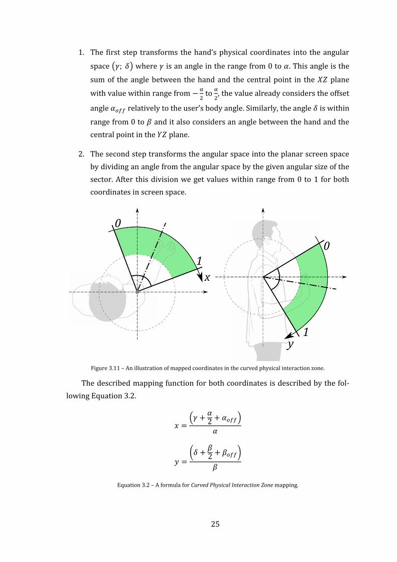
1. The first step transforms the hand’s physical coordinates into the angular
space ( ) where is an angle in the range from 0 to . This angle is the
sum of the angle between the hand and the central point in the plane
with value within range from
to
, the value already considers the offset
angle relatively to the user’s body angle. Similarly, the angle is within
range from 0 to and it also considers an angle between the hand and the
central point in the plane.
2. The second step transforms the angular space into the planar screen space
by dividing an angle from the angular space by the given angular size of the
sector. After this division we get values within range from 0 to 1 for both
coordinates in screen space.
Figure 3.11 – An illustration of mapped coordinates in the curved physical interaction zone.
The described mapping function for both coordinates is described by the fol-
lowing Equation 3.2.
(
)
(
)
Equation 3.2 – A formula for Curved Physical Interaction Zone mapping.

26
3.1.4.3. Comparison of the Physical Interaction Zone Designs
Each of the two different approaches in spatial mapping between the user’s
hand movements in physical space and the cursor on the screen, see also 3.1.5,
possess different behavior of the cursor’s movement on the screen.
In the case of the Planar Physical Interaction Zone the cursor position on the
screen corresponds to the user’s hand position in physical space. It means that the
trajectory of the cursor’s movement on the screen corresponds exactly to the tra-
jectory of the user’s hand movement in the physical space without any changes.
For the user, this effect may be in some aspects unnatural because the user must
move his or her hand along the plane which in the result requires more
concentration in combination with a need for moving the hand in a certain way
that it is within the boundaries of the rectangular area. This movement could be
complicated due to the fact that the user cannot see how far the rectangular area is
and according to it the user must concentrate on the hand’s distance from his body
all the time.
The other approach is using the Curved Physical Interaction Zone and in con-
trast to the Planar Physical Interaction Zone it considers the natural movement of
the user’s hand. This natural movement is based on the fact that the hand is mov-
ing around a central point of its movement. For instance, we can assume a shoul-
der position as the central point. The design of curved physical interaction zone is
based on mapping the user’s hand position into the screen space using angles
between the central point and the user’s hand position which results in the arc–
shaped trajectory of user’s hand movement. As a result, the approach allows the
user move the cursor more naturally by moving his or her hand around his or her
shoulder. According to the natural basis of this physical interaction zone, design of
the user’s hand movement doesn’t require much concentration and the user
doesn’t need to move his or her hand in an unnatural manner.

27
3.1.5. Cursor
The basic natural user interaction is based on the possibility of selecting,
clicking or dragging controls on the screen in the same way as when we are using
the mouse or touch input. The fundamental principle is using a cursor which rep-
resents a location where the user’s action is intended to be performed. Chapter
3.1.4 describes the mapping function which determines the cursor’s position on
the screen. The function is based on mapping the user’s hand position in physical
space into the screen space using a defined physical interaction zone.
Inasmuch as the on–screen position acquired by the mapping function may
contain inaccuracies caused by the imprecise user pose recognition, we can refine
the cursor’s position by adding a filter to reduce jittery and jumpy behavior [14].
In most cases the application of a filter could result in increasing lag. Lag can
greatly compromise the experience, making it feel slow and unresponsive.
Figure 3.12 – Cursor's position filtering and a potential lag. [14]
As a filter for refining the cursor’s position, one may use, for example, a simple
low–pass filter [29] described by an Equation 3.3. This filter makes the cursor’s
movement smoother and in certain extent is able to eliminate undesired jittery
and jumpy behavior but it is at the cost of the resulting lag. The final behavior of
the filter depends on a value of its weight which specifies an amount of the posi-
tion increment. Finding a good weight for balance between smoothness and lag
can be tough.
( ) [ ( )]
( ) [ ( )]
Equation 3.3 – Low–pass filter with two samples.
The final cursor’s position can be filtered also in order to increase the accu-
racy when the cursor is getting closer to the desired position on the screen. We can
modify the low–pass filter in order to filter the cursor’s position depending on its
acceleration. In other words, the position will be filtered only when it moves

28
slowly. This is scenario in where the user expects the most precise behavior of the
cursor with the intention of pointing at the desired place. We can even setup the
filter so that it won’t filter fast movements at all and will be applied only for slow
movements. This may be done by setting the filter’s weight dynamically according
to the actual cursor’s acceleration. A function of the filter’s weight is illustrated by
Figure 3.13 and described by Equation 3.4 where is cursor’s acceleration, is
the weight, is the upper limit for a resulting weight and is an acceleration
threshold specifying from which value the weight is modified.
√( ) ( )
( ) ( )
Equation 3.4 – A weight function for the modified low–pass filter.
Figure 3.13 – A weight function for the modified low–pass filter dependent on the cursor’s acceleration.
In case of two cursors appearing simultaneously on the screen, a problem may
occur, for example, when we move the right hand to the left side and the left hand
to the right side of the interaction zone. We notice that cursors are swapped on the
screen. This may lead to the confusion of the user and make the interaction incon-
venient. In order to prevent such a behavior the mutual horizontal position of the
cursors should be limited so the cursors won’t swap.
The current input methods consider a visual
feedback that tells the user at which position his or
her intended action will be performed. For instance,
for such a visual feedback the mouse uses a cursor
usually represented by an arrow drawn on the
screen. In case of the touch interface there is usually
nothing drawn on the screen but the user’s finger
itself is used as the visual feedback. Although, these
inputs use different ways of dealing with the visual
feedback, they both assure the user about the location where his or her action is
intended to be performed. In this regard, the natural user interaction is similar to
Figure 3.14 – A concept of the user's hand visualization using a cursor.

29
the mouse input. It doesn’t have straightforward mapping for the hand’s position
in physical space into the screen space so we need to provide an additional visual
feedback on the screen. A final look of the cursor should correspond to the nature
of the interaction. In case we interact by using hands, the cursor should be illus-
trated by a hand shape. Also the cursor’s graphics should change during the action
in order to show whether the cursor is or is not in action state.
3.1.6. Action Triggering
Analogously to the mouse or touch input we need to detect an action such as a
click, drag, pan, zoom, etc. Because the touch–less interaction doesn’t provide any
action triggering using a button like the mouse does, or any contact with the
screen like the touch input does, we need to detect the action in other way which
doesn’t require physical contact with the computer or any of its peripheries.
This chapter describes two different ways of action triggering which can be
used with the touch–less interface.
3.1.6.1. Point and Wait
The first Kinect touch–less interface for Xbox 360 came up with a simple way
how to trigger the click action. It is based on the principle that a user points the
cursor on a button he wants to click on and then he or she waits a few seconds
until the click is performed. This principle may be called as the Point and Wait
interaction.
The point and wait interaction is able to detect primarily the hand’s click and
drag and multi–touch gestures zoom and pan. The click is the simplest one. When
there is only the primary cursor tracked and it stands still for a certain time a click
is performed on the cursor’s position. In case of both tracked cursors there is only
down event raised on the primary cursor instead of the click which allows the
cursor to drag. The dragging ends when the primary cursor stands still for a
certain time again. Multi–touch gestures are possible to do when both cursors are
tracked. The primary cursor has to stand still for a certain time and then both
cursors must move simultaneously.
Additionally, this kind of interaction requires a visualization of the progress of
waiting in order to inform the user about the state of the interaction. Also, it is im-
portant to choose a timing that doesn’t frustrate users by forcing the interaction to
be too slow [14].

30
3.1.6.2. Grip
One of the possible action triggers based on a natural user’s acting is Grip
action. The grip action is detected when user clenches his or her hand in a fist. It’s
very simple to use because, for instance, for clicking it is the natural hand gesture
and it’s also easily understandable.
The grip action is able to perform click, drag and multi–touch gestures such as
zoom and pan. Practically, the grip action may perform any multi–touch gesture
using two hands.
Recognition of the grip action is based on computer vision and uses a depth
frame and a tracked skeleton as its input. The recognition itself is a difficult prob-
lem because it works with noisy and unpredictable data which are affected by the
actual user’s pose. It means that the hand shape is not constant due to its pose
facing the sensor and in certain situations it could look same for both states of
action.
The Kinect for Windows SDK v1.7 came up with the Interaction Toolkit,
described in chapter 1.1.1, which provides, among other things, recognition of the
grip action. The recognizer is based on the machine learning algorithms which are
able to learn and then identify whether the user’s hand is clenched in a fist. The
recognition is successful in most cases but still there can be some situations in
which the action could be recognized wrongly. These situations can occur when
the hand is rotated in such a way that it is invisible for the depth sensor. It hap-
pens, for example, when the users point their fingers toward the sensor.
3.1.7. Gestures
The natural user interface enables a new way of interacting by recognizing
patterns in user’s movement that match a specific gesture. The gestures allow exe-
cuting predefined actions very quickly and naturally, but the quality of the result-
ing user’s experience critically depends on the gesture’s design. If the gesture is
not reliable, the application will feel unresponsive and difficult to use. There are
many factors and situations which must be considered for a reliable and respon-
sive gesture design in order to avoid users’ frustration [14].
3.1.7.1. Designing a Gesture
A reliable gesture design considers its variability depending on the user’s
interpretation of a gesture that could be completely different from the other users.

31
Also, the design must take into account that once the user has engaged with the
system, the sensor is always monitoring and looking for patterns that match a
gesture. It means that the design should be able to distinguish intentional gestures
and ignore other movements such as touching face, adjusting glasses, drinking, etc.
Another influence on the gesture’s practicability has a choice of one or two–
handed gestures. One handed gesture is more intuitive and easier to do than two–
handed. Also, when there is a two–handed gesture designed, it should be symmet-
rical which is more intuitive and comfortable for the user. A target usage of both
gesture types should be also considered. One–handed gestures should be used for
critical and frequent tasks so the user can do them quickly and accurately. For
advanced and non–critical tasks two–handed gestures should be used.
The gesture’s design should also consider fatigue caused by performing the
gesture repeatedly. If the users get tired because of a gesture, they will have a bad
experience and will probably quit. One possible way of reducing fatigue is, in the
case of one–handed gesture, that it should allow being used for both hands so the
user can switch hands.
For successful human–computer interaction the requisite feedback deemed
essential [30]. The gestures are ephemeral and they don’t leave any record of their
path behind. It means, when the user makes a gesture and gets no response or
wrong response, it will make it difficult to him or her to understand why the ges-
ture was not accepted. This problem could be overcome by adding an interface for
indicating crucial states of the current progress of the recognition.
Design and implementation of a gesture recognizer is not part of the Kinect for
Windows SDK and thus the programmer must design and implement his own
recognition system. There are a couple of approaches used today from bespoken
algorithms to reusable recognition engines enabling to learn different gestures.
The basic approach is based on the algorithmic detection where a gesture is rec-
ognized by a bespoken algorithm. Such an algorithm uses certain joints of the
tracked skeleton and based on their relative position and a given threshold it can
detect the gesture. For recognizing more gestures there is a need of designing and
implementing a new recognizer for each one. It means that with a new gesture the
result size of the application grows and also a larger number of algorithms must be
executed to determine if a gesture has been performed. Other, more generic,
approaches use machine learning algorithms such as Neural Networks [31] or

32
Dynamic Time Warping [32]. These methods are more complicated but the
resulting algorithm is more generic and allows the recognition more complicated
gestures.
In the following chapters a design of two basic gestures such as a wave ges-
ture and swipe gesture is described. Both gestures are designed for algorithmic
detection and demonstrate the basic approach for creating gesture recognition.
3.1.7.2. Wave gesture
One of the most common gestures is the Wave gesture. People use wave ges-
tures for saying hello or good–bye. In the natural user interaction, the wave
gesture can be analogously used for saying the user is ready to begin the experi-
ence. The wave gesture has been used by Microsoft and proven as a positive way
of determining user intent for engagement [14].
The wave is a gesture with simple movements which makes it easy to detect
using an algorithmic approach [33]. From observation of the common way in
user’s waving we can notice the relationship between the hand and the arm during
the gesture. The gesture begins in neutral position when the forearm is perpendic-
ular to the rest of the arm. If the hand’s position exceeds a certain threshold by
moving either to the left or to the right, we consider this a segment of the gesture.
The wave gesture is recognized when the hand oscillates multiple times between
each segment. Otherwise, it is an incomplete gesture. From this observation one
can see that for recognition, two tracked skeleton’s joints, the hand joint and the
elbow joint are needed. Figure 3.15 illustrates all three gestures’ states and their
relationship.
Figure 3.15 – An illustration describing joints of interest and their relative position for wave gesture
recognition. [33]

33
3.1.7.3. Swipe gesture
Another basic gesture is the Swipe gesture. This gesture is commonly used for
getting to something next or previous such as a next or previous page, slide, etc.
The gesture consists of the hand’s horizontal movement from the right to the left
or from the left to the right. Depending on the movement direction there are two
swipe gesture types distinguished, the right swipe and left swipe. Even though the
direction of movement is different, the gestures are recognized on the same prin-
ciple.
According to the simple movements from which the swipe gesture consists, it
can be easily detected using an algorithmic approach. The user usually makes a
swipe by a quick horizontal movement which is, however, unambiguous because it
may be also one of the wave gesture’s segments. The swipe gesture detecting algo-
rithm should be designed more strictly in order to make the gesture more clear
and reliable. For instance, the right swipe gesture will be recognized by the
designed recognizer as the right hand’s horizontal movement performed from a
certain horizontal distance from the shoulder on the right side and moving along
the body to the certain horizontal distance from the shoulder on the left side. Also,
the swipe gesture will be detected only when the hand is above the elbow in order
to avoid detecting swipe gesture in situations like when user is relaxed. Based on
the described design of the gesture, it can be seen that for recognition there are
three tracked skeleton’s joints needed, the hand, elbow and shoulder. The swipe
gesture design, and the relationship between joints, is illustrated by Figure 3.16.
Figure 3.16 – An illustration describing joints of interest and their relative position for the swipe gesture recognition (green area indicates a horizontal movement range that is recognized as a swipe gesture).

34
3.2. Implementation
This chapter describes an implementation of the Touch–less Interface for fur-
ther use in an implementation of the prototypes, see also 3.3 . The implementation
of the touch–less interface consists of data layer for sensor’s data processing and
representation, Touch–less interactions using hands for moving cursor and a
several kinds of ways for performing action, Gesture Interface for user’s hand
movement classification, touch integration with WPF and Windows 8 input, and
visualization for giving a supportive visual feedback to the user.
3.2.1. Architecture
The Touch–less Interface is designed and implemented on the three layer ar-
chitecture. A data layer along with an application layer is implemented in the
library named KinectInteractionLibrary. A presentation layer is implemented as a
WPF control library and its implementation is located in the KinectInteraction-
WPFControls library.
The data layer implements a wrapper for encapsulating basic data structures
for more comfortable way of Kinect data processing. Also, it implements logic of
data sources for depth, color, skeleton and facial data input. This layer creates a
generic interface between the sensor’s implementation and application layer. The
application layer implements a functionality of the touch–less interface, interac-
tion detection, interaction’s quality system and gesture interface. The presentation
layer is based on WPF and it is implemented on top of the application layer. This
layer provides basic controls for sensor’s data visualization and foremost the visu-
alization for touch–less and gesture interaction. Also, on the same layer an integra-
tion of the touch–less interface with the user input is implemented. The architec-
ture is described by the Figure 3.17.
Figure 3.17 – A block diagram of the implementation architecture.
Visualization Integration with the UI
Touch-less Interface
Touch-less Interactions
Interaction Detector
Interaction Quality System
Gesture Interface
NUI Data Structures
Kinect for Windows SDK
Presentation Layer
Application Layer
Data Layer

35
3.2.2. Data Structures
The implementation is based on the data structures which represent data
provided by the sensor. The Kinect for Windows SDK implements its own data
structures but these structures have limited implementation. The data of these
structures is not possible to clone and regarding to its implementation with non–
public constructors there is not possible to instantiate them instantly and thus it is
not possible to use them for custom data. This limitations have been overcame by
encapsulating data from these native structures into the own object data
representation. Particular encapsulated data structures are described in the
following chapters.
3.2.2.1. Depth Frame
A depth image is represented and implemented by the DepthFrame class.
The class contains information about a depth image’s format, image’s dimensions,
time of its capture and above all the depth pixels data and user index data. Depth
data contains data of the depth image that are represented as an array of 16–bit
signed integer values where each value corresponds to a distance in physical space
measured in millimeters. An invalid depth value -1 means that the pixel is a part of
a shadow or it is invisible for the sensor. User index data are represented as a byte
array of the same length as the depth data array. The user index data contain
information about which pixel is related to which tracked user.
The DepthFrame class provides an interface for a basic manipulation with
depth and user index data such as getting and setting a depth or user index value
at given and coordinates, flipping and cropping depth image. The class also
provides a method Clone() for creation of its copy.
A class diagram describing a DepthFrame object representation is illustrated
by the Figure 3.18.

36
Figure 3.18 – A class diagram describing the depth frame data structure.
3.2.2.2. Color Frame
A color image is represented and implemented by the ColorFrame class. The
class contains information about a color image format, image dimensions and
image data. The image data are represented as a byte array. The color image is
stored in ARGB format, it means, the image pixels are stored as a sequence of four
bytes in order blue, green, red and alpha channel.
The ColorFrame class provides an in-
terface for a basic manipulation with pixel
data such as getting and setting pixel color at
given and coordinates and flipping the im-
age. The class also provides a method
Clone() for creation of its copy.
A class diagram describing a Color-
Frame object representation is illustrated by
the Figure 3.19.
Figure 3.19 – A class diagram describing the
color frame data structure.

37
3.2.2.3. Skeleton Frame
Information about all tracked skeletons is represented and implemented by
the SkeletonFrame class. This class contains an array of currently tracked skel-
etons. The class provides a method for getting a skeleton by a given id and also
provides a method Clone() for creation of its deep copy.
A tracked skeleton is represented and implemented by the Skeleton class.
The skeleton is identified by its ID stored in the property Id. An association of the
skeleton to the user’s information in the depth image is realized by the property
UserIndex which identifies depth pixels related to the tracked skeleton. The
skeleton data are composed of 20 types of joints representing user’s body parts of
interest. All of these 20 tracked joints are stored in the skeleton’s collection
Joints. In addition, the Skeleton class provides a property Position con-
taining a position of the tracked user blob [33] in physical space. The property
TrackingState contains information about a state of skeleton’s tracking. If the
skeleton is tracked, the state is set to a value Tracked, when the skeleton is not
tracked but the user’s blob position is available, the state has a value
PositionOnly, otherwise the skeleton is not tracked at all and the state is set to
a value NotTracked. In case of the user’s blob is partially out of the sensor’s field
of view and it’s clipped the property ClippedEdges indicates from which side
the tracked user blob is clipped.
The joint is represented and implemented by the SkeletonJoint class. The
class contains a position of the joint in physical space. A tracking state of the joint
is stored in property TrackingState. If the joint is tracked the state is set to a
value Tracked. When the joint is overlaid by another joint or its position is not
possible to determine exactly the tracking state has a value Inferred, although,
the position is tracked it could be inaccurate. Otherwise, when the joint is not
tracked its tracking state is set to a value NotTracked.
A class diagram describing a SkeletonFrame object representation is illus-
trated by the Figure 3.20.

38
Figure 3.20 – A class diagram describing architecture of the skeleton frame data structure.
3.2.2.4. Face Frame
Information about all tracked faces is represented and implemented by the
FaceFrame class. This class contains a property TrackedFaces which is real-
ized as a hash table where the tracked faces are stored under the related skeleton’s
as a key. It allows getting a tracked face for a given skeleton conveniently only
by passing the skeleton’s as a key.
Every single tracked face is represented by an instance of the TrackedFace
class. The class describes a tracked face by its rectangle in depth image coordi-
nates, see also 2.3.1, by its rotation, described in chapter 2.3.4, position in physical
space and its 3D shape projected into the color image.
A class diagram describing a FaceFrame object representation is illustrated
by the Figure 3.21.

39
Figure 3.21 – A class diagram describing architecture of the face frame data structure.
3.2.3. Data Sources
Logic for processing of obtained data from the sensor is implemented by data
sources. There are four types of data sources: DepthSource, ColorSource,
SkeletonSource and FaceSource which are additionally composed into the
KinectSource which handles the logic for obtaining data from the sensor. Each
data source implements logic for handling a given data input and processes ob-
tained data into the corresponding data structure. When data processing is fin-
ished the data source forwards the result data structure through its event–based
interface for the further data processing.
Figure 3.22 – A block diagram describing the data sources architecture and their output data.
3.2.3.1. Depth Source
A depth image obtained from the sensor is processed into the DepthFrame
data structure using logic implemented by the KinectDepthSource class. The
processing is handled by the method ProcessDepthImage() that passes a
native depth image represented by the Microsoft.Kinect.DepthImage-
Depth Source
Color Source
Skeletal Source
Face Source
Kinect for Windows SDKKinect Toolkit
Depth Frame
Color Frame
Skeletal Frame
Face Frame
Generates

40
Frame structure as its parameter. Depth pixel data are copied into the internal
buffer and then each pixel is decomposed into the depth and user index
component, see also chapter 2.3.1 for the depth pixel’s format description. When
the depth pixel data processing is done a new instance of the DepthFrame data
structure is created on the processed data and it is passed on by raising an event
DepthFrameReady.
The KinectDepthSource class also
provides properties that describe physical
parameters of the depth sensor such as a
value of the minimal or maximal depth
which the sensor is able to capture and a
value of the nominal horizontal, vertical
and diagonal field of view in degrees. The
class also provides a property for selecting
between default and near range mode of
the depth sensor, see also chapter 2.3.1.
Before the depth image data pro-
cessing can be started the depth source
has to be enabled. It can be done by
setting the Enabled property to true
which initializes the sensor’s depth data
stream. In default the depth source is
disabled so the first step before perform-
ing a depth image data processing is its
initialization by setting the Enabled
property to true.
A class diagram describing a KinectDepthSource object representation is
illustrated by the Figure 3.23.
3.2.3.2. Color Source
A color image obtained from the sensor is processed into the
KinectColorFrame data structure using logic implemented by the Color-
Source class. The processing is handled by the method ProcessColor-
Image() that passes a native color image represented by the Microsoft.Kin-
ect.ColorImageFrame structure as its parameter. Color pixel data are copied
Figure 3.23 – A class diagram describing an object model of the depth data source.

41
into the internal buffer which is then used for creating of a new ColorFrame
instance. Finally, the new instance of the ColorFrame is passed on by raising an
event ColorFrameReady.
Before the color image data pro-
cessing can be started the color source has
to be enabled. It can be done by setting the
Enabled property to true which initial-
izes the sensor’s RGB camera data stream.
In default the color source is disabled so
the first step before performing a color
image data processing is its initialization
by setting the Enabled property to true.
A class diagram describing a Kine-
ctColorSource object representation is
illustrated by the Figure 3.24.
3.2.3.3. Skeleton Source
Logic for a processing of skeleton data obtained from the Kinect’s skeleton
data stream is implemented by the KinectSkeletonSource class. The pro-
cessing is handled by the method ProcessSkeletonData() that passes a
native skeleton frame represented by the Microsoft.Kinect.Skeleton-
Frame structure as its parameter.
Skeletons data are copied into the
internal buffer. The processing algo-
rithm goes through all skeletons and
finds those which are in tracked state.
The tracked skeleton’s data are used for
creating of a new instance of Skeleton
class and the new instance is inserted
into the list of tracked skeletons. After
all skeletons are processed, a new
instance of the SkeletonFrame class
is created on the basis of the list of
tracked skeletons.
Figure 3.24 – A class diagram describing an object model of the color data source.
Figure 3.25 – A class describing an object model of the skeleton data source.

42
Before the skeleton data processing can be started the skeleton source has to
be enabled. It can be done by setting the Enabled property to true which ini-
tializes the sensor’s skeleton data stream. In default the skeleton source is disabled
so the first step before performing a skeleton data processing is its initialization by
setting the Enabled property to true.
A class diagram describing a KinectSkeletalSource object representa-
tion is illustrated by the Figure 3.25.
3.2.3.4. Face Source
For this work the Face Tracking feature, distributed as an additional library by
Microsoft, has been designed as a separated data source which is implemented by
the KinectFaceSource class. This class implements logic for processing depth,
color and skeletal data into the tracked face data structure. The face tracking itself
is handled by the external native library FaceTrackLib. A call of the native methods
for face tracking is done by using the .NET wrapper for the external native library
implemented by the Microsoft.Kinect.Toolkit.FaceTracking assembly.
The face source extends the basic face tracking functionality by an implemen-
tation of a timer for measuring the tracked face’s lifetime. Depending on the envi-
ronmental conditions, the face tracker can lose a track of the tracked face unpre-
dictably. The lifetime timer can prevent a loss of the tracked face caused by a noise
in a several frames. If the face is tracked the lifetime timer is active and has its
highest value. In case of the face tracker lost face’s track and the lifetime timer is
active, there is a last tracked face used as the currently tracked data. But when the
timer ticks out the tracked face is identified as not tracked. In the result the track-
ing is more stable, however, when the face tracker loses a track of the face, the face
source may use outdated and thus the inaccurate data. The target lifetime value in
milliseconds can be set by the FaceTrackingTTL property.
The face tracking is a very time intensive operation. Due to this fact the face
source implements the face tracking processing using a parallel thread. This solu-
tion prevents from dropping sensor’s data frames because the time intensive
tracking operation is performed in the other thread independently and it doesn’t
block a main thread in which the other data are processed.

43
As the face tracking is a time intensive
operation it is also CPU intensive. In some
cases there is not required to track a face in
each frame so in order to optimize the per-
formance the face source implements a
frame–limiter that allows setting a required
tracking frame rate. The lower the frame
rate is, the less performance is needed and
the face tracking operation won’t slow down
the system. The target frame rate can be set
by the Framerate property.
A class diagram describing a Kinect-
FaceSource object representation is
illustrated by the Figure 3.26.
3.2.3.5. Kinect Source
All data sources, described in previous chapters, are composed into the
KinectSource class. This class implements logic for controlling the sensor and
also it handles all events of the sensor. The Kinect source provides an interface for
enabling and disabling the sensor by calling the methods Initialize() and
Uninitialize().
The most important task of the Kinect source is handling of the sensor’s
AllFramesReady event. There are processed all data in the handler method us-
ing the corresponding data sources. After data processing of all sources is finished,
the Kinect source passes on all processed data by raising its event
AllFramesReady.
According to the described implementation, there is not possible to run the
particular data sources individually without using the Kinect source. In practice,
there is an instance of the KinectSource created and the particular data sources
are accessed through the interface of this instance.
A class diagram describing a KinectSource object representation is illus-
trated by the Figure 3.27.
Figure 3.26 – A class diagram describing an object model of the face data source.

44
Figure 3.27 – A class diagram describing an object model of the Kinect data source.
3.2.3.6. Kinect Source Collection
Dynamic Kinect sources instantiation and disposition depending on whether
the device has been connected or disconnected is implemented by the
KinectSourceCollection class. The class is implemented on the Singleton
design pattern. The implementation is based on the Microsoft.Kin-
ect.KinectSensorCollection class and handles its event StatusChanged
which indicates a sensor’s status change. Regarding the state the collection creates
or removes an instance of the KinectSource class for the given sensor. For each
status change there is the KinectSourceStatusChanged event raised in order
to inform about the change. In case of at least one sensor is connected at the time
the collection is instantiated, the event for informing about the status change is
raised for the connected Kinect source with a current sensor’s state. This
implementation is advantageous because it doesn’t require double check of the
connected device during the application start as it requires in case of an
implementation of the native sensor collection. Everything what is needed for the
KinectSource initialization is to register the KinectSourceStatusChanged
event and initialize the source in the event handler method as it is described by the
following code strip.

45
public void Initialize() { KinectSourceCollection.Sources.KinectSourceStatusChanged +=
Sources_KinectSourceStatusChanged; } private void Sources_KinectSourceStatusChanged(object sender,
KinectSourceStatusEventArgs e) { switch (e.Status) { case Microsoft.Kinect.KinectStatus.Connected: // kinect source initialization e.Source.Initialize(); // enables depth source e.Source.DepthSource.Enabled = true; // enables color source e.Source.ColorSource.Enabled = true; // enables skeleton source e.Source.SkeletonSource.Enabled = true; break; case Microsoft.Kinect.KinectStatus.Disconnected: // enables depth source e.Source.DepthSource.Enabled = false; // enables color source e.Source.ColorSource.Enabled = false; // enables skeleton source e.Source.SkeletonSource.Enabled = false; // kinect source uninitialization e.Source.Uninitialize(); break; } }
Currently instantiated and connected Kinect sources it is possible to enumer-
ate by using the collection’s indexer.
A class diagram describing a KinectSourceCollection object represen-
tation is illustrated by the Figure 3.28.
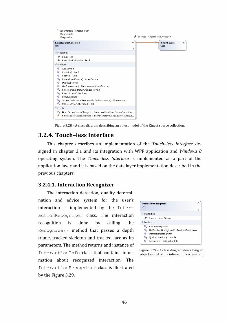
46
Figure 3.28 – A class diagram describing an object model of the Kinect source collection.
3.2.4. Touch–less Interface
This chapter describes an implementation of the Touch–less Interface de-
signed in chapter 3.1 and its integration with WPF application and Windows 8
operating system. The Touch–less Interface is implemented as a part of the
application layer and it is based on the data layer implementation described in the
previous chapters.
3.2.4.1. Interaction Recognizer
The interaction detection, quality determi-
nation and advice system for the user’s
interaction is implemented by the Inter-
actionRecognizer class. The interaction
recognition is done by calling the
Recognize() method that passes a depth
frame, tracked skeleton and tracked face as its
parameters. The method returns and instance of
InteractionInfo class that contains infor-
mation about recognized interaction. The
InteractionRecognizer class is illustrated
by the Figure 3.29.
Figure 3.29 – A class diagram describing an object model of the interaction recognizer.

47
The recognizer detects the user’s face angle using a given tracked face’s yaw
pose and evaluates whether the angle is within the specified range. Similarly, the
recognizer determines the user’s body angle using a given skeleton. The angle is
measured between shoulder joints around the axis. The recognizer also uses dis-
tances of the user’s position measured from each side of the sensor’s field of view.
On the basis of these distances and the equation described in chapter 3.1.3 a
quality of each particular joint is evaluated. If the user’s face angle, body angle and
a quality of joints is within specified ranges the interaction is indicated as detected.
In case of an insufficient quality the recognizer generates a list of advices
indicating what the user should do for a better interaction experience.
Figure 3.30 – A class diagram describing an object model of the interaction info data structure.
All these information are stored in an instance of the InteractionInfo
class and they are passed on for an evaluation in further implementation. A class
diagram describing the InteractionInfo object representation is illustrated by
the Figure 3.30.
The advices are evaluated on the worst found quality among all joints and on
whether the face angle and body angle are within their ranges. When the user is
not looking toward the sensor in the certain range of angle, the recognizer

48
generates an advice saying that the user should look at the sensor. Similarly, when
user turns his or her body out of the certain angle from the sensor, the recognizer
generates an advice notifies that the user should turn his body back toward the
sensor. The interaction quality is used for evaluating to which side the user is
approaching too close and on the basis of this information the recognizer can
generate an advice saying which way the user should move in order to stay within
the sensor’s field of view.
3.2.4.2. Touch–less Interactions Interface
A purpose of the touch–less interactions interface is to implement logic for
using the user’s hands for moving the cursor on the screen in order to allow basic
operations similar to multi–touch gestures, see also 2.1.1. The touch–less interac-
tion interface is implemented by the TouchlessInteractionInterface
class.
The touch–less interactions interface is based on the interaction recognizer,
gesture interface and a given action detector. The interaction recognition is used
for detection of the user’s interaction quality. The gesture interface enables to
detect a wave gesture which is required for a login to the interaction. The action
detector evaluates a current user’s action such as performing of the down or up
event that is analogous to mouse button down and up event, see also 3.2.4.3.
An interaction starts when the tracked user’s wave gesture is recognized.
Depending on the hand by which the user waved the primary hand is set to left or
right hand. The primary hand is meant to be used in further implementation on
top of the interaction system so it is made accessible through the
PrimaryCursor property. After the user is logged in the interaction system
starts to track the user’s hands movement and monitor the user’s interaction
quality. Regarding the user’s interaction quality, the system processes user’s hand
movement into the movement of the cursors on the screen. When the user’s
interaction is detected and overall interaction quality is sufficient the system
performs mapping of the hand’s position from physical space into the screen space
using a mapping function described by the current type of physical interaction
zone, see also 3.1.4. In case of two cursors on the screen, the resulting position of
the cursors is checked in order to prevent their swapping, see also 3.1.5. Then, an
action for the cursors is evaluated using the given action detector. Finally, the
system raises an event CursorsUpdated where it passes on the updated cursors
represented by a list of instances of the TouchlessCursor class.

49
The system allows switching the interaction between tracked users standing
toward the sensor. The current user is selected by waving his or her hand. The
system notifies the application about the change of the interacting user by raising
an event TrackedUserChanged. In case of there is at least one user tracked, the
system state, accessible through the State property, is set to Tracking state,
otherwise if there is no tracked user the system’s state is set to Idle and it is
waiting for the user’s login by using the wave gesture.
A class diagram describing an object representation of the touch–less interac-
tions interface is illustrated by the Figure 3.31.
Figure 3.31 – An object model of the touch–less interaction interface.
3.2.4.3. Action Detector
The action detector is implemented by the abstract class Action-
DetectorBase and it is used for detecting an action which is analogous to mouse
button down and up event. The action can be detected in different ways. There are

50
two approaches to action detection implemented: Point and Wait, see also 3.2.4.4,
and Grip, see also 3.2.4.5.
The action detector creates basis logic for performing down and up events on
cursors. The logic also implements a cursor’s position snapping to the position on
which the cursor was located before an action was detected. This functionality
enables to easily perform a click action.
The ActionDetectorBase class provides events CursorDown and
CursorUp notifying about whether the down or up action happened. For setting
the current action the class provides internal methods OnCursorDown() and
OnCursorUp() for handling logic of these actions. These methods are supposed
to be called in the further implementation of the particular action detector. The
detection of the action is supposed to be done by implementing the abstract
method Detect() which passes a collection of cursors, skeleton of interest and
current depth frame as its parameter. These parameters are used in the further
implementation of the method for detecting the final action.
A class diagram describing the ActionDetectorBase object representation
is illustrated by the Figure 3.32.
Figure 3.32 – A class diagram describing an object model of the action detector base.
3.2.4.4. Point and Wait Action Detector
An action detector for the Point and Wait action, described in chapter 3.1.6, is
implemented by the class PointAndWaitActionDetector. The class is based
on the abstract class ActionDetectorBase and implements logic for detecting
the action by overriding the abstract method OnDetect().

51
The point and wait action detector is implemented as a finite–state machine
[34]. Appendix A contains the state chart of the detection algorithm. The action
detector is able to detect primary hand’s click and drag and multi–touch gesture
zoom and pan. All actions are timer–based, which means that in order to perform
an action a cursor has to stand still for a certain time. This basic detection of an
action can be divided into two steps. The first step detects whether the cursor
stands still. The second step measures how long the cursor didn’t move. There is a
certain threshold for the detection of cursor’s movement. When the threshold is
not exceeded a timer is activated. When the timer ticks out an action is detected.
Otherwise, if the cursor moves before the timer ticks out no action is detected.
The point and wait action detector detects primary hand’s click and drag and
multi–touch gesture zoom and pan. The click is the simplest one. When there is
only the primary cursor tracked and it stands still for a certain time a click is per-
formed on the cursor’s position by continuous calling of OnCursorDown()and
OnCursorUp() methods. In case of both tracked cursors there is called only the
OnCursorDown()method in order to allow dragging. The dragging finishes by
calling the OnCursorUp() method when the primary cursor stands still for a
certain time again. Multi–touch gesture is possible to do when both cursors are
tracked. The primary cursor has to stand still for a certain time and then both
cursors must move immediately. Then, the OnCursorDown() method is called
for both cursors. The multi–touch gesture finishes when the primary cursor stands
still for a certain time and then the OnCursorUp() method is called for both
cursors.
3.2.4.5. Grip Action Detector
An action detector for the Grip action, described in chapter 3.1.6.2, is imple-
mented by the class GripActionDetector. The class is based on the abstract
class ActionDetectorBase and implements logic for detecting the action by
overriding the abstract method OnDetect().
The implementation is based on the Microsoft Kinect Interaction Toolkit, see
also 2.3.5, which is used for a grip action recognition implemented by the class
GripActionRecognizer. The implementation processes current data con-
tinuously for detecting a grip press and release actions. A current state of the grip
action can be acquired by calling the method Recognize()on an instance of the
class.

52
When grip action is recognized the action detector calls the
OnCursorDown() method in order to raise a down event. Then, when the grip
action is released, the OnCursorUp() method is called in order to notify about an
up event. In the result the Grip action detector provides functionality similar to
traditional multi–touch and allows performing any multi–touch gesture that uses
up to two touches.
3.2.4.6. Gesture Interface
A system for detection and classification of user’s gestures, described in chap-
ter 3.1.7, is represented by the Gesture Interface. The architecture of the gesture
interface consists of the class GestureInterface and the abstract class
Gesture. The GestureInterface class contains a list of instantiated gestures
and provides an interface for specifying which gestures the interface should use.
The gestures for detection are specified by calling a method AddGesture() that
passes a type of the gesture as its parameter. The gesture may be removed from
the list using a method RemoveGesture() that passes a type of the gesture to
remove as its parameter. When the gesture is detected successfully the gesture
interface raises an event GestureRecognized that passes an instance of the
GestureResult class containing an instance of the recognized gesture and the
related skeleton for further association of the gesture with a specific tracked
skeleton. A constructor of the gesture interface requires an instance of the
skeleton source. The gesture interface registers the SkeletonFrameReady
event of the skeleton source and in its handler method it handles recognition for
all gestures in the list.
The abstract class Gesture represents a gesture’s detection logic. A gesture
implemented on the basis of this class must implement all its abstract methods. A
method Initialize() implements an initialization code for the gesture and
provides an instance of the current skeleton source. A method Recognize()
implements the bespoken algorithm for gesture detection using passed tracked
skeleton and its result returns in the instance of the GestureResult class. For
resetting the gesture’s state there is the method Reset() that sets all variables to
the default values. The class provides the GestureState property informing
about the current detection state. When the gesture detection state has changed
the StateChanged event is raised.

53
An object representation of the gesture interface is illustrated by the Figure
3.33.
Figure 3.33 – An object model of the gesture interface.
3.2.4.7. Wave Gesture Recognizer
Detection of the wave gesture, described in chapter 3.1.7.2, is implemented by
the class WaveGestureRecognizer. The detection algorithm is implemented as
a finite–state machine [34] illustrated by the Figure 3.34.
Figure 3.34 – A state diagram of the wave gesture detection.
A detection algorithm is implemented inside the method TrackWave() that
passes a tracked skeleton as its parameter and returns a value true in case of
success and a value false in case of non–detected gesture. The algorithm uses the
Neutral position
None
Hand moved within neutral zone
Hand moved out of the netural zone
Left position
Hand moved to the left
Right position
Hand moved to the right
Failure
Timeout
Hand is under the elbow
Hand moved withinneutral zone Gesture
detected
Timeout tick
A required number ofiterations has been done

54
hand and the elbow joints for detecting the wave. First of all, it checks a tracking
state of both joints in order to don’t detect the gesture for non–tracked or inferred
joints. Then, a vertical position of both joints is compared and when the hand is
above the elbow the algorithm starts to look for the neutral hand’s position and
left or right hand’s oscillation. The neutral position is detected when the hand’s
joint is in the vertical line with the elbow and their horizontal relative position is
in the tolerance given by a threshold. When the hand’s position exceeds the
threshold by the horizontal movement to the left or to the right, the recognizer
increments a value of the current iteration. After a certain number of iterations in
certain timeout, the algorithm detects the wave gesture. The state of the gesture
provided by the property GestureState indicates whether the hand is on the
right or left side relatively to the neutral position or whether the gesture detection
failed.
Figure 3.35 – An object model of wave gestures.
The wave recognizer is used for implementation of the right and left wave ges-
ture. These gestures are represented by classes RightWaveGesture and
LeftWaveGesture implemented on the abstract class Gesture. Each gesture
has its own instance of the recognizer. The recognizer is set for detecting the
desired right or left hand through its constructor.

55
An object model of the wave gesture implementation is described by the
Figure 3.35.
3.2.4.8. Swipe Gesture Recognizer
Detection of the swipe gesture, described in chapter 3.1.7.3, is implemented
by the class SwipeGestureRecognizer. The detection algorithm is imple-
mented as a finite–state machine [34] illustrated by the Figure 3.36.
Figure 3.36 – A state diagram of the swipe detection.
A detection algorithm is implemented inside the method TrackSwipe() that
passes a tracked skeleton as its parameter and returns true in case of success and
false in case of non–detected gesture. The algorithm uses the hand, elbow and
shoulder joints for the detecting the swipe gesture. First of all, the tracking state of
each joint is checked in order to detect the gesture only if all joints are tracked.
Then, the hand position is checked whether it is located within an area above the
elbow. When the hand is within the area, the algorithm begins monitoring the
hands movement. For instance, the right swipe is initiated when the right hand’s
horizontal position exceeds a given threshold on the right side relatively to the
right shoulder. The gesture is detected if the hand horizontally exceeds the right
shoulder position by a given threshold to the left. This threshold is usually greater
than the previously mentioned one. If the gesture is not finished in a certain time
the gesture is cancelled and it is not detected.
The swipe recognizer is used for implementation of the right and left swipe
gesture. These gestures are represented by classes RightSwipeGesture and
LeftSwipeGesture implemented on the abstract class Gesture. Each gesture
has its own instance of the recognizer. The recognizer is set for detecting the right
or left hand through its constructor.
Hand is within
detection zone
None
Hand moved within detection zone
Hand moved out of the detection zone
Hand away from body
Gesture detected
Hand moved horizontally awayfrom body in a certain distance
Timer tick
Timeout
Hand movedhorizontally in
a certain distance

56
An object model of the swipe gesture implementation is described by the
Figure 3.37.
Figure 3.37 – An object model of the swipe gestures.
3.2.4.9. Iterative NUI Development and Tweaking
A development of the NUI is not as straightforward as a development of other
UI. The reason is primarily in the unpredictability of the user’s individual access to
using the natural gestures and movements. In the other words, not everybody con-
siders a gesture made in one way as natural as
the same gesture made by other person.
Although, the meaning of the gesture is the
same the movements are different either
because of the various high of the persons or
difference in their innate gesticulation. In the
result a final setup of the natural interactions
has an influence on the resulting user’s
experience and also on fatigue and comfort of
the natural interaction.
Figure 3.38 – An iteration process of the NUI development.

57
The finding of the optimal setup for the natural interactions is the most
important and circuitous process of the NUI development. Usually, it is based on
the iterative process that starts with a new design of the setup. Then, the setup is
tested by the widest range of users in order to evaluate its usability. The iteration
process is illustrated by the Figure 3.38. On the basis of evaluation the usability
tests a new iteration is initiated. The final setup will never be ideal for all users,
but through conducting frequent usability tests the final setup will be a
compromise that works for the most people.
3.2.5. Integration with WPF
The integration of the touch–less interface with the WPF application is done
via implementing the abstract class TouchDevice that creates a base for any
touch input of the WPF framework. The abstract class provides methods for re-
porting the down, up and move actions. These methods are intended to be called
by the particular implementation of the touch input.
The WPF touch input base for the touch–less interactions is implemented by
the abstract class NuiTouchDevice. This class implements basic logic for
switching between mouse and touch events
in order to handle actions via mouse when
the touch events have not been handled by
the application. Whether the touch events
have been handled is indicated by the flag
value returned by methods
ReportDown(), ReportUp(),
ReportMove(). The invoking of the
mouse operations is done through the
Windows API that is wrapped by the static
class MouseWin32. The abstract class
NuiTouchDevice provides virtual
methods OnDown(), OnUp() and
OnMove(). These methods are intended to
be called by the further implementation
based on this class in order to handle the
desired actions. The algorithm is described
by the Figure 3.39.
OnDown() called
Event has been handled
Raising Touch Down event by
ReportDown()
Down event reported
Yes
Raising Mouse Down event
No
Figure 3.39 - A block diagram of the WPF touch device implementation.

58
The final touch–less input device is implemented by the class Touch-
lessInputDevice. The class inherits from the abstract class NuiTouch-
Device described above. The input device represents one cursor on the screen
which means there are two instances of the input device needed for creating a full
two–handed touch–less solution. Each input device is identified by its ID. The ID
should be unique and that’s why the constructor requires a type of the cursor as a
one of its parameters. As the other parameters the constructor demands a
presentation source specifying on which graphical elements the input device is
intended to be used and an instance of the natural interaction interface, described
in chapter 3.2.4.2. The touch–less input device registers update event of the
interaction interface. When cursors are updated the input device stores the last
state of the given cursor type, calculates the cursor’s position on the screen and
then it calls the corresponding report methods regarding the cursor’s current
action.
3.2.6. Integration with Windows 8
The integration with the operating system is done via the Touch Injection API
available only in the Windows 8. It enables any application to generate touch mes-
sages and inject them into the system’s message loop. Microsoft doesn’t provide
any .NET wrapper for this API and that’s way the wrapper has been implemented
as a part of this thesis. The wrapper is implemented as the C++ project TouchDLL
and the C# class TouchOperationsWin8.
The touch injection is initialized by calling a method InitializeTouch()
that passes a maximal number of touches as its parameter. A particular touch is
represented by the structure POINTER_TOUCH_INFO containing information
about its position, state, pressure, etc. When any touch is intended to be injected,
an instance of this structure is created, all its attributes specified and then passed
into the system’s message loop by calling the method SendTouchInput().
The integration of the touch–less interactions is implemented by the class
TouchlessDriverWin8. The implementation combines touch injection for
multi–touch interaction with the system using the touch–less cursors and integra-
tion of calling keyboard shortcuts using swipe gestures. The driver’s constructor
requires an instance of the natural interaction interface, described in chapter
3.2.4.2. The driver registers update event of the interaction interface. When

59
cursors are updated the driver calculates the cursor’s position on the screen and
then injects touches with a state regarding the cursor’s current action.
The driver also registers the event for recognized gesture. When the swipe
gesture is recognized the driver calls the corresponding keyboard shortcut. There
are two sets of shortcuts. The first one is used for presentation so it simulates a
press of the Page Up key for the left swipe gesture and a press of the Page Down
key for the right swipe gesture. The second set provides keyboard shortcuts for
showing the start screen by using the left swipe gesture and closing an active
application by the right swipe gesture.
3.2.7. Visualization
The visual feedback of the touch–less interface is implemented on the WPF
and it is divided into two parts: Cursors and Assistance visualization. The following
chapters describe an implementation of both these parts and demonstrate their
final graphical look.
3.2.7.1. Overlay Window
The visualization is implemented as an overlay window. In order to overlay
the applications by the visualization window, the window is set to be the top most.
Also, the applications must be visible through the overlay window so the window
is made borderless and transparent. In addition, the window is set as a non–
focusable and its focus is not set after startup which disables any noticeable
interaction with the window.
The WPF window enables to overlay desktop by drawing transparent graphics
which makes the visualization more attractive and also practical in that way the
visualization is not too invasive and doesn’t distract the user. But there is one
problem to solve in order to make the window invisible for the mouse and touch
events and allow them to be handled by the applications and not by the overlay
window. This problem has been resolved using the Windows API for setting a flag
WS_EX_TRANSPARENT to the window’s extended style. This makes the window
transparent for any input events. The method for creating the transparent window
is implemented as an window’s extension method SetInputEventTrans-
parent() in the static class WindowExtensions.
The cursors and assistant visualization are implemented in their own
separated overlay window. The reason of their separation into their own windows

60
is the resulting performance. A rendering of the visualization graphics is time–
consuming and it slows down rendering and the resulting effect is less smooth and
could make the using of the touch–less interface uncomfortable.
3.2.7.2. Cursors Visualization
The cursors visualization shows a position of the user’s hands mapped into
the screen space. The position is visualized by drawing graphics at the position of
the cursor. The cursor’s graphical representation is a hand–shape image that is
made at least 70% transparent with regard to make the controls under the cursor
visible. In an inactive state, when the cursor has no action and it is only moving
across the screen in order to point a desired place, an opened palm hand–shape is
used as the image. When the cursor is in an action state, a closed palm hand–shape
is used as the image. It helps the users to recognize whether their action is per-
formed or they should do the action more clearly. In addition, a progress circle
indicating a timeout for firing an action is added for the point and wait action trig-
ger. All three described graphical representations of the cursor’s state are illus-
trated by the Figure 3.40.
Figure 3.40 – An illustration of cursor actions, from the left: point and wait timer, grip released, grip pressed.
The cursors visualization is implemented as an overlay window, described in
chapter 3.2.7.1, by the class InteractionOverlayWindow. It contains an in-
stance of the natural interaction interface and handles its update event. When cur-
sors are updated, the visualization invalidates a visual, maps the cursor’s position
into the screen space and renders the cursor’s graphics on the window.
3.2.7.3. Assistance Visualization
A help to achieve the best experience is provided by the assistance visualiza-
tion. It shows a contour of the user as it is seen by the sensor and gives the user an
overview about his or her visibility to the sensor. The data for rendering the con-
tour are taken from the current depth frame which contains the depth information
along with the player segmentation data representing a relation between the
depth data and the user’s tracked skeleton, see also 2.3.1. By combining the infor-
mation a contour of the user is separated from the rest of the scene and written as

61
ARGB pixels into the WritibleBitmap instance. Then, the resulting bitmap is
rendered on the window. The final look of the user’s contour is illustrated by the
Figure 3.41.
Figure 3.41 – An illustration of the user's contour.
In case of an inconvenient user’s pose, the assistance visualization can give
corresponding advices to the user such as an instruction about which way the user
should move to get back within the sensor’s field of view or instruct the user to
turn his body or face toward the sensor. These instructions are shown in a notifi-
cation bar bellow the user’s contour.
Also, the assistance visualization can give a visual feedback for gestures. It
shows instructions of the crucial states for the currently performed gesture. For
example, it indicates which way the users should move their hand in order to make
the wave gesture right, or it indicates whether the gesture was detected or can-
celed. This visualization is used also for creating a login visualization that helps the
user to get engaged with the touch–less interface.
The assistance visualization is implemented as a WPF user control by the class
UserAssistantControl. The control is composed into an overlay window im-
plemented by the class AssistantOverlayWindow in order to enable the assis-
tant control to be shown above the rest of the running applications. The assistant
control contains an instance of the natural interaction interface and handles its
update event. When the cursors are updated the visualization invalidates a visual
and renders a contour of the tracked user based on the last available depth frame
data. If any advice is available the assistance control shows it by fading in a notifi-
cation bar bellow the user’s contour. The final look of the assistance visualization
is illustrated by the Figure 3.42.

62
Figure 3.42 – An illustration of the assistance visualization.
3.3. Prototypes
As a part of this thesis is an implementation of a set of prototypes demon-
strating different approaches in the touch–less interface design. There have been
two prototype applications implemented based on the implementation of the
touch–less interaction described in chapter 3.2.4 . The first prototype is aimed at
subjective tests of using the touch–less interactions for clicking, dragging and
multi–touch gestures with different types of action triggers and physical interac-
tion zones. The second prototype integrates the touch–less interactions with the
Windows 8 operating system via the touch injection interface and allows testing
the touch–less interface in the real case scenario.
3.3.1. Test Application
The first prototype application is aimed at subjective tests of using the touch–
less interactions. The prototype is designed for evaluating a subjective experience
in using the touch–less interface for common actions like clicking, dragging and
multi–touch gestures. Multi–touch integration with the prototype application is
done by implementing a custom WPF input device described in chapter 3.2.5. In
order to evaluate mentioned subjective experience, the prototype consists of the
following six scenarios (an illustration for each scenario is attached as the
appendix B):
1. A scenario with a large button that is moved across the screen and user is
intended to click on it. A positions of the button are chosen with regard to
evaluate user’s subjective experience in clicking on the button in standard
and extreme situations such as button located at the corners of the screen
or buttons located too near to each other.
2. A scenario similar to the first one but instead of the large button there is a
small button used in order to evaluate user’s subjective experience in
clicking and pointing on very small objects.

63
3. A scenario aimed on the user’s experience in dragging objects onto the
desired place. The test is designed in such a way the objects must be
dragged from the extreme positions, which are the corners of the screen,
and must be dragged into the middle of the screen. In order to avoid user’s
first–time confusion and help him or her to get easily oriented in the task
there are added visual leads showing which object is supposed to be moved
on which place.
4. A scenario evaluating user’s experience in dragging objects similar to the
previous one. In this test the user moves objects from the middle of the
screen into the screen’s corners.
5. A scenario aimed on the user’s experience in scrolling among a large num-
ber of items in a list–box. As the list–box control is used a touch control
from the Microsoft Surface SDK 2.0 [35] enabling to scroll the items using
touch gestures. The test is designed in such a way the user must select one
given item which is located in the first third of the list. This particular loca-
tion is chosen due to evaluation of the precision during the scrolling the
items. At the beginning, the user doesn’t know how far the object is so he or
her starts to list through the list quickly, but then the item shows up and the
user must response in such a way he or she is able to click on it.
6. A scenario evaluating user’s experience in using multi–touch gestures with
the touch–less interactions. The test uses the WPF Bing Maps control [36]. It
supports multi–touch gestures such as pan and pinch to zoom combined
with a rotation.
The prototype combines two ways of action triggering, described in chapter
3.1.6, with two types of the physical interaction zone, described in chapter 3.1.4. In
the result the test application creates the following four prototypes, each with a
different configuration of the touch–less interactions:
1. Planar physical interaction zone, with Point and Wait action trigger.
2. Planar physical interaction zone, with Grip action trigger.
3. Curved physical interaction zone, with Point and Wait action trigger.
4. Curved physical interaction zone, with Grip action trigger.
The application is implemented as one executable KinectInteractionApp.exe
which takes a path to the configuration XML file as its argument. The XML file con-

64
tains the entire set of the configurable variables for the touch–less interaction.
There have been created four configuration XML files each for one configuration
described above.
3.3.2. Touch–less Interface for Windows 8
A prototype aimed at using the touch–less interactions in the real case sce-
nario with Windows 8 operating system. The Windows 8 has been designed espe-
cially for touch devices, which makes it a suitable candidate for evaluating the
user’s subjective experience in using the touch–less interactions with the current
applications and UI.
The application consists of the touch–less interface including gestures, its
integration with the system and its visualization. The touch–less interactions are
based on the Curved physical interaction zone, see also 3.1.4.2, and Grip for trigger-
ing the actions, see also 3.2.4.5. The integration with the operating system is done
via the Touch Injection API available only in the Windows 8, see also 3.2.6. The
visualization consists of the visualization of the cursors and assistance control
described in chapter 3.2.7.
The Windows 8 doesn’t allow the applications to overlay Windows 8 UI inter-
face usually. Particularly, for intend of drawing the graphical elements above the
applications, the prototype application has needed to be signed by a trusted
certificate and the UI access changed for the highest level of its execution. After
these tweaks the desired visualization of the touch–less interactions overlaying
the Windows UI interface has been done. The appendix D illustrates the Windows
8 application overlaid by the touch–less interaction visualization.
The application enables to use the touch–less interactions through the regular
multi–touch input. In addition, it makes it possible to use swipe gestures for
executing actions. The application implements two ways of using the gestures:
1. Swipe gestures for presentation. The user can list between slides, pictures
or pages via right or left swipe.
2. Swipe gestures for the system actions such as showing the Start screen by
using the left swipe and closing the current application by using the right
swipe.

65
The prototype application is implemented as an executable application
KinectInteractionWin8App.exe which takes a path to the configuration XML file as
its argument. The XML file contains the entire set of the configurable variables for
the touch–less interaction including a setting of the Windows 8 integration. The
setting enables to choose a behavior of the integration between using gestures for
a presentation or for the system actions.
3.4. User Usability Tests
This chapter describes the methodology of the subjective usability tests and
evaluates their results in order to find out which approaches are more and less
suitable for the realization of the touch–less interactions.
3.4.1. Test Methodology
According to the nature of the NUI, there is no particular test methodology for
an objective evaluation of the level of usability for the concept of the touch–less
interactions. The concept could be usable for some people but for other people
might be very difficult to use. It means that the conclusive results can be collected
by conducting usability tests which evaluate the subjective level of usability and
the level of comfort for each tested user.
For an evaluation of usability of the NUI, designed and implemented in this
thesis, a test was designed and aimed at user experience in using the touch–less
interactions for common actions such as a click, drag, scroll, pan and zoom. The
test uses a setup with a large 60” inches LCD panel with the Kinect for Windows
sensor placed under the panel. The tested user is standing in front of the LCD panel
in a distance of about one and a half meter. The setup is illustrated by the Figure
3.43.

66
Figure 3.43 – A setup for user usability tests.
The test investigates the user’s subjective experience in the level of comfort
and level of usability. The test is divided into two parts:
The first part investigates the user’s experience in using particular action trig-
gers described in chapter 3.1.6 and types of interaction zones described in
chapter 3.1.4. As a testing application, the Test Application, described in chap-
ter 3.3.1., is used. The aim of the test is to evaluate the users’ subjective levels
of usability and the levels of comfort.
The level of usability is evaluated for both types of action trigger. The level
of usability is defined by a rating scale divided into a scale of ten. The rating 9
represents the intuitive experience without requisite need for learning and the
rating 0 represents the worst experience when the interactions are not usable
at all. The rating scale is described by the Table 1:
Intuitive Usable Requires a
habit
Difficult to use Unusable
9 8 7 6 5 4 3 2 1 0
Table 1 – The level of usability rating scale.
The level of comfort is evaluated for both types of interaction zone. The
level of comfort is defined by a rating scale divided into a scale of six. The rat-
ing 5 represents the comfortable experience without any noticeable fatigue and
the rating 0 represents a physically challenging experience. The rating scale is
described by the Table 2:

67
Comfortable Fatigue Challenging
5 4 3 2 1 0
Table 2 – The level of comfort rating scale.
The second part investigates the usability of the touch–less interactions in real
case scenario by using it for controlling the Windows 8 UI and applications. As
a testing application, the Touch–less Interface for Windows 8, described in chap-
ter 3.3.2, is used. The level of usability in the real case scenario is defined by a
rating scale divided into eight degrees. The rating 7 represents the comfortable
and intuitive experience without any noticeable fatigue and the rating 0 repre-
sents a physically and practically challenging experience. The rating scale is de-
scribed by the Table 3:
Intuitive and
comfortable
Usable, no fatigue Usable, fatigue Challenging
7 6 5 4 3 2 1 0
Table 3 – The level of usability rating scale for the real case scenario.
The test conducts the user’s subjective level of usability for the following
Windows 8 applications and common actions:
o Using swipe gestures for presentation
o Using swipe gesture for showing the Start screen
o Using swipe gesture for closing an active application
o Launching a Windows 8 application
o Selecting items in Windows 8 application
o Targeting and selecting small items
o Using maps
o Using web browsers
A test form used for conducting the user’s subjective level of usability, level of
comfort and level in experience using touch–less interactions for controlling the
Window 8 UI is attached in the appendix E.
3.4.2. Tests Results
This chapter shows the results of the subjective usability tests. The tests have
been conducted by testing 15 users of various heights and various knowledge in
human–computer interactions. The following charts visualize the results in partic-
ular aspects of the designed test described in chapter 3.4.1:

68
The level of comfort for the Planar Physical Interaction Zone:
Figure 3.44 – A chart showing the results of the level of comfort for Planar Physical Interaction Zone.
The level of comfort for the Curved Physical Interaction Zone:
Figure 3.45 – A chart showing the results of the level of comfort for Curved Physical Interaction Zone.
1
3
9
2
0 0
5 - Comfortable 4 - Comfortable 3 - Fatiguing 2 - Fatiguing 1 - Challenging 0 - Challenging
0
1
2
3
4
5
6
7
8
9
10
The Level of Comfort - Planar PhIZ
5
10
0 0 0 0
5 - Comfortable 4 - Comfortable 3 - Fatiguing 2 - Fatiguing 1 - Challenging 0 - Challenging
0
2
4
6
8
10
12
The Level of Comfort - Curved PhIZ

69
The level of usability for Point and Wait action trigger:
Figure 3.46 – A chart showing the results of the level of usability for Point and Wait action trigger.
The level of usability for Grip action trigger:
Figure 3.47 – A chart showing the results of the level of usability for Grip action trigger.
0
1
2
3
4
5
6
7
8
9
The Level of Usability - Point and Wait action trigger
Click Drag Scroll Pan Zoom
0
1
2
3
4
5
6
7
8
9
10
The Level of Usability - Grip action trigger
Click Drag Scroll Pan Zoom

70
The level of usability for the real case scenario:
Figure 3.48 – A chart showing the results of the level of usability for swipe gestures.
Figure 3.49 – A chart showing the results of the level of usability for targeting and selecting items.
0
1
2
3
4
5
6
7
8
9
The Level of Usability - Swipe Gestures
Swipe gestures for Presentation Left swipe gesture for showing the Start
Right swipe gesture for closing an application
0
1
2
3
4
5
6
7
8
9
The Level of Usability - Targeting and Selecting Items
Targeting and selecting large items Trageting and selecting small items

71
Figure 3.50 – A chart showing the results of the level of usability for using Windows 8 applications.
3.4.3. Tests Evaluation
This chapter evaluates the results of the usability tests shown in the previous
chapter 3.4.2. The level of comfort, level of usability and level of usability in real
case scenario are evaluated. Based on these results, the most comfortable and usa-
ble design will be chosen for the final implementation in chapter 3.5.
3.4.3.1. The Level of Comfort
The level of comfort has been investigated for two types of the physical inter-
action zone, the planar (3.1.4.1) and curved (3.1.4.2). The Figure 3.44 shows that
the planar physical interaction zone was fatiguing for most of the tested users.
Keeping hands in a certain distance toward the sensor was sometimes fatiguing
especially for users of low height. They often reported that they are getting tired
and were missing the possibility of resting their arms at their side so they would
relax the hand.
Figure 3.45 shows that the curved physical interaction zone has been found as
a more comfortable design than the planar physical interaction zone. The tested
users were more comfortable with the possibility of relaxing the hand at their side
0
1
2
3
4
5
6
7
The Level of Usability - Windows 8 Applications
Launching Windows 8 application Using Windows 8 maps Using Windows 8 web browser

72
and more natural movements of their hand during the interaction. The only diffi-
culty that was reported was the variable cursor’s behavior when the user was ap-
proaching the left or the right side of the screen. It has shown that such behavior is
caused by the spherical design of the interaction zone.
3.4.3.2. The Level of Usability
The level of usability has been investigated for two types of action triggers, the
Point and Wait action trigger (3.1.6.1) and Grip action trigger (3.1.6.2). Figure 3.46
shows that the designed point and wait action trigger for doing a click is usable but
it was not fully intuitive for most of the tested users. The rest of them reported
that such a kind of interaction requires it to become a habit for them. The results
for other types of interactions such as drag, scroll, pan and zoom show that such a
design of action triggering is not suitable for performing advanced interactions.
The Figure 3.47 shows that the Grip action trigger has been reported as a
much more intuitive and usable solution for performing all kinds of investigated
interactions. For most of the tested users, without any knowledge of such a way of
action triggering, the grip was the first gesture they used for clicking or dragging
items. More complicated usability was reported with using of multi–touch gestures
and gesture for scrolling by users which were not familiar with using multi–touch
gestures. Foremost, the test has shown that using the multi–touch gesture for
zoom could be difficult due to a need for coordinating both hands on the screen.
3.4.3.3. The Level of Usability for Real Case Scenario
Figure 3.48 shows the results of using the touch–less interface for controlling
the real Windows 8 applications. The test was investigating eight types of interac-
tions. The results have shown that the most intuitive and usable way for control-
ling the application was by using left and right swipe gesture. Generally, the touch–
less interactions were also evaluated as a usable but quite fatiguing way for
controlling Windows 8 applications. Some difficulties have been observed with
using maps and web browser. There the users had to use multi–touch gestures
which, according to the usability tests results in chapter 3.4.3.2, have been
investigated as unintuitive for touch–less interactions. More difficult experience
was reported when the users were trying to click on small buttons and items due
to the precision of the Skeletal Tracking and Grip action detector in case of users of
lower height.

73
3.4.4. Tests Conclusion
The tests have evaluated that for the best level of comfort, the design of the
Curved Physical Interaction Zone should be used, due to its more natural way of
mapping the hand movements onto the cursor’s position. The hand Grip gesture is
seen as the most intuitive solution for triggering actions. The tests showed that
such a way of interaction is intuitive and usable in most cases.
A combination of the Curved Physical Interaction Zone and Grip trigger action
has been tested in the real case scenario with controlling the Window 8 applica-
tion. The tests have shown that such a touch–less interface design is usable and the
users are able to use it immediately with a minimal familiarization. The tests also
have shown a disadvantage of the current design. The disadvantage is that the
users start to feel fatigue after about 15 minutes of using touch–less interactions.
3.5. Touch–less Interface Integration with ICONICS
GraphWorX64™
In this chapter, an integration of the touch–less interface, designed in chapter
3.1 with the ICONICS GraphWorX64™ application will be described. The integration
demonstrates a practical application of the touch–less interactions in the real case
scenario.
3.5.1. About ICONICS GraphWorX64™
The GraphWorX64™ is part of the bundle of the industrial automation soft-
ware GENESIS64™ developed by the ICONICS company. The bundle consists of
many other tools such as AlarmWorX64™, TrendWorX64™, EarthWorX™, and others
[37]. GraphWorX64™ is a rich HMI and SCADA data visualization tool. It allows
users to build scalable, vector–based graphics that do not lose details when it is
zoomed on. It allows users to build intuitive graphics that depict real world
locations and integrate TrendWorX64™ viewers and AlarmWorX64™ viewers to
give a full picture of operations. It makes configuring all projects quick and easy.
Users can reuse content through the GraphWorX64™ Symbol Library, Galleries and
Templates as well as configure default settings to allow objects to be drawn as
carbon copies of each other without additional styling.
GraphWorX64™ allows creating rich, immersive displays with three dimen-
sions. It makes easy to create a 3D world with Windows Presentation Foundation
(WPF) and get a true 360 degree view of customer’s assets. It makes it possible to

74
combine 2D and 3D features using WPF with annotations that move with 3D
objects or create a 2D display that can overlay a 3D scene. It utilizes the 2D vector
graphics to create true to life depictions of customer’s operations and view them
over the web through WPF.
GraphWorX64™ is at the core of the GENESIS64™ Product Suite. It brings in
content and information from all over GENESIS64™ such as native data from SNMP
or BACnet [38] devices, AlarmWorX64™ alarms and TrendWorX64 trends. Through
a desire to have a consistent experience all of GENESIS64™ takes advantage of the
familiar ribbon menus found throughout integrated applications, such as Microsoft
Office. [39]
3.5.2. Requirements
The ICONICS Company required using the touch–less interactions with the
GraphWorX64™ displays. According to the application of the displays in industry
and energetics the interactions must be safe and secured from any unpredictable
behavior. The following list shows the crucial requirements for the touch–less
interface integration:
Possibility of use with WPF and standard Windows controls, such as scrollbar,
list view, ribbon bar, etc.
Prevent a random user tracking by using a login gesture.
Prevent losing the engagement with the system when someone else comes in
front of the sensor.
Prevent unpredictable behavior caused by a user’s unintended interaction.
Provide an appropriate visual feedback.
3.5.3. Touch–less Interface Integration
The integration of the touch–less interface with the GraphWorX64™ applica-
tion can be divided into two parts. The first part deals with integrating the interac-
tions into the user input system of the application and the second part creates a
visualization layer on it.
From the user usability tests conclusion evaluated in chapter 3.4.4, the inte-
grated touch–less interface is designed on the Curved Physical Interaction Zone
described in chapter 3.1.4.2 and the Grip action trigger described in chapter
3.1.6.2. A combination of these two designs has resulted in the most natural and
comfortable touch–less interface solution.

75
According to company’s know–how the integration of the touch–less interface
with the product is described only superficially and demonstrates the results of
the whole integration process. Also, in order to create an industrial solid solution
suitable for use in real deployment, the whole implementation part of this thesis
has been rewritten and the resulting source code is licensed by the ICONICS
Company.
The overview of the integration architecture is described by the block diagram
in the Figure 3.51.
Figure 3.51 – Overview of the touch–less interface integration with GraphWorX64™ application.
3.5.3.1. Interactions
The GraphWorX64™ application is based on more than one presentation
framework. Although, it is a Windows Forms application, the displays are based on
the WPF due to its vector based graphics. It leads to making the integration able to
handle mouse and touch input simultaneously. It has been resolved by using the
WPF integration using the modified WPF touch input device implementation
described in chapter 3.2.5. According to its design based on the standard mouse
input and WPF touch input, it enables to use the touch–less interactions for inter-
acting with the standard windows controls and with the WPF controls including its
touch interface.
Touch–less gestures such as left and right swipe gesture were also integrated..
All controls composed in the GraphWorX64™ display have a pick action which says
what is going to happen when a user clicks on it. In order to integrate touch–less
gestures with the display, it has been made possible to associate these gestures
with any pick action. It enables the user, for instance, to change the actual view of
GraphWorX
WPF
Touch-less Visualization
WPF touch-less Input Device
Touch-less Interface
Kinect for Windows SDK

76
the 3D scene by using only swipe gestures without any need for having any device
in the hands or having any contact with the computer.
3.5.3.2. Visualization
A touch–less interaction visualization has been implemented as an overlay
window, see also 3.2.7.1. This solution enables to use and visualize touch–less
interaction over the whole screen. The visualization consists of the cursors visuali-
zation, described in chapter 3.2.7.2, and the assistance visualization described in
chapter 3.2.7.3. The resulting look of the touch–less interface inside the
GraphWorX64™ application is illustrated by the Figure 3.52.
Figure 3.52 – A screenshot of the touch–less interface in the GraphWorX64™ application.
3.5.3.3. Safety and Reliability
The ICONICS Company required a safe and reliable functionality of the touch–
less interface in order to prevent any unwanted situations due to an unpredictable
behavior of the interactions. The requirement has been resolved by integrating the
interaction detection designed in chapter 3.1.2 and the interaction quality system
designed in chapter 3.1.3. As a result, the system is able to recognize intended
interactions by observing the user’s body and face pose and also is able to deter-
mine whether the user’s position is suitable for a comfortable interaction.

77
4. Conclusion
This thesis has dealt with the design, implementation and integration of the
touch–less interface in the real case scenario. The work was divided into three
parts. Each part dealt with one aspect of the assignment.
The first part of the thesis was dealing with the design of the touch–less
interface and its implementation as a prototype library. Based on this library a set
of five prototypes has been implemented. Four prototypes demonstrate different
designs for the touch–less interactions and the fifth prototype integrates the
touch–less interactions with the Windows 8 operating system in order to enable
the interactions to be used for common tasks.
In the second part of the thesis, subjective user tests were performed in order
to investigate which approach for designing the touch–less interactions is the most
intuitive and comfortable. The results have shown that the best design is a combi-
nation of curved physical interaction zone (3.1.4.2), based on the natural move-
ment of the human hand, and grip action triggering (3.1.6.2).
The third part of the thesis was dealing with an integration of the designed
touch–less interface with the ICONICS GraphWorX64™ application as a demonstra-
tion of using the touch–less interactions in real case scenario. The final implemen-
tation of the touch–less interface for the application has been based on the results
from the performed subjective user tests.
As a result of this thesis a touch–less interface has been designed and imple-
mented. The final implementation was based on the subjective user tests that
evaluated the most natural approaches for realization of the touch–less interac-
tions. The resulting touch–less interface has been integrated with the ICONICS
GraphWorX64™ application as a demonstration of using the touch–less interac-
tions in a real case scenario. According to these conclusions, all points of the thesis
assignment have been accomplished.

78
List of Abbreviations
MS – Microsoft
PC – Personal Computer
WPF – Windows Presentation Foundation
NUI – Natural User Interface
UI – User Interface
API – Application Programming Interface
FOV – Filed of View
PhIZ – Physical Interaction Zone
RGB – An additive color model consisted of Red, Green and Blue component
IR – Infrared light spectrum
CPU – Central Processing Unit
HMI – Human–Machine Interface
SCADA – Supervisory Control and Data Acquisition
SNMP – Simple Network Management Protocol

79
List of Equations EQUATION 3.1 – AN EQUATION OF THE INTERACTION QUALITY FUNCTION. ........................................... 21
EQUATION 3.2 – A FORMULA FOR CURVED PHYSICAL INTERACTION ZONE MAPPING. ............................ 25
EQUATION 3.3 – LOW–PASS FILTER WITH TWO SAMPLES. ....................................................................... 27
EQUATION 3.4 – A WEIGHT FUNCTION FOR THE MODIFIED LOW–PASS FILTER. ...................................... 28
List of Tables TABLE 1 – THE LEVEL OF USABILITY RATING SCALE. .................................................................................. 66
TABLE 2 – THE LEVEL OF COMFORT RATING SCALE. .................................................................................. 67
TABLE 3 – THE LEVEL OF USABILITY RATING SCALE FOR THE REAL CASE SCENARIO. ................................ 67
List of Figures FIGURE 2.1 – AN ILLUSTRATION OF THE KINECT FOR XBOX 360 TOUCH–LESS INTERFACE. [7] .................. 5
FIGURE 2.2 – KINECT FOR WINDOWS SENSOR COMPONENTS. [12] ........................................................... 7
FIGURE 2.3 – KINECT FOR WINDOWS SENSOR FIELD OF VIEW. [15] ........................................................... 8
FIGURE 2.4 – AN ILLUSTRATION OF THE DEPTH STREAM VALUES. ........................................................... 10
FIGURE 2.5 – AN ILLUSTRATION OF THE DEPTH SPACE RANGE. ................................................................ 10
FIGURE 2.6 – AN ILLUSTRATION OF THE SKELETON SPACE. ...................................................................... 12
FIGURE 2.7 – TRACKED SKELETON JOINTS OVERVIEW. ............................................................................. 12
FIGURE 2.8 – AN ILLUSTRATION OF THE FACE COORDINATE SPACE. ........................................................ 14
FIGURE 2.9 – TRACKED FACE POINTS. [25] ................................................................................................ 14
FIGURE 2.10 – HEAD POSE ANGLES. [25] ................................................................................................... 14
FIGURE 2.11 – GRIP ACTION STATES (FROM THE LEFT: RELEASED, PRESSED). .......................................... 15
FIGURE 3.1 – AN ILLUSTRATION OF THE KINECT’S SETUP. ........................................................................ 17
FIGURE 3.2 – AN ILLUSTRATION OF THE INTENDED AND UNINTENDED USER INTERACTION BASED
ON A FACE ANGLE. ............................................................................................................. 18
FIGURE 3.3 – AN ILLUSTRATION OF THE UNSUITABLE SCENARIO FOR THE RECOGNITION OF THE
TOUCH–LESS USER INTERACTION. ..................................................................................... 18
FIGURE 3.4 – AN ILLUSTRATION OF ADVICES FOR HELPING USER FOR BETTER EXPERIENCE. .................. 19
FIGURE 3.5 – AN ILLUSTRATION OF THE EXAMPLE OF A PROBLEMATIC SCENARIO FOR TOUCH–
LESS INTERACTION. ............................................................................................................ 20
FIGURE 3.6 – AN ILLUSTRATION OF THE SENSOR’S FIELD OF VIEW (FOV) WITH INNER BORDER
AND THE INTERACTION QUALITY FUNCTION Q(D). ............................................................ 20
FIGURE 3.7 – AN ILLUSTRATION OF THE QUALITY DETERMINATION FOR EACH PARTICULAR JOINT
INDIVIDUALLY (THE GREEN JOINTS HAVE THE HIGHEST QUALITY, THE RED JOINTS
HAS THE LOWEST QUALITY). .............................................................................................. 21
FIGURE 3.8 – A PLANAR PHYSICAL INTERACTION ZONE DESIGN (GREEN AREA). ...................................... 23
FIGURE 3.9 – AN ILLUSTRATION OF MAPPED COORDINATES INTO THE PLANAR MAPPED HAND
SPACE. ................................................................................................................................ 23

80
FIGURE 3.10 – AN ILLUSTRATION OF THE CURVED PHYSICAL INTERACTION ZONE (GREEN AREA). ......... 24
FIGURE 3.11 – AN ILLUSTRATION OF MAPPED COORDINATES IN THE CURVED PHYSICAL
INTERACTION ZONE............................................................................................................ 25
FIGURE 3.12 – CURSOR'S POSITION FILTERING AND A POTENTIAL LAG. [14] ........................................... 27
FIGURE 3.13 – A WEIGHT FUNCTION FOR THE MODIFIED LOW–PASS FILTER DEPENDENT ON THE
CURSOR’S ACCELERATION. ................................................................................................. 28
FIGURE 3.14 – A CONCEPT OF THE USER'S HAND VISUALIZATION USING A CURSOR. .............................. 28
FIGURE 3.15 – AN ILLUSTRATION DESCRIBING JOINTS OF INTEREST AND THEIR RELATIVE
POSITION FOR WAVE GESTURE RECOGNITION. [33] ......................................................... 32
FIGURE 3.16 – AN ILLUSTRATION DESCRIBING JOINTS OF INTEREST AND THEIR RELATIVE
POSITION FOR THE SWIPE GESTURE RECOGNITION (GREEN AREA INDICATES A
HORIZONTAL MOVEMENT RANGE THAT IS RECOGNIZED AS A SWIPE GESTURE). ............ 33
FIGURE 3.17 – A BLOCK DIAGRAM OF THE IMPLEMENTATION ARCHITECTURE. ...................................... 34
FIGURE 3.18 – A CLASS DIAGRAM DESCRIBING THE DEPTH FRAME DATA STRUCTURE............................ 36
FIGURE 3.19 – A CLASS DIAGRAM DESCRIBING THE COLOR FRAME DATA STRUCTURE. .......................... 36
FIGURE 3.20 – A CLASS DIAGRAM DESCRIBING ARCHITECTURE OF THE SKELETON FRAME DATA
STRUCTURE. ....................................................................................................................... 38
FIGURE 3.21 – A CLASS DIAGRAM DESCRIBING ARCHITECTURE OF THE FACE FRAME DATA
STRUCTURE. ....................................................................................................................... 39
FIGURE 3.22 – A BLOCK DIAGRAM DESCRIBING THE DATA SOURCES ARCHITECTURE AND THEIR
OUTPUT DATA. ................................................................................................................... 39
FIGURE 3.23 – A CLASS DIAGRAM DESCRIBING AN OBJECT MODEL OF THE DEPTH DATA SOURCE. ........ 40
FIGURE 3.24 – A CLASS DIAGRAM DESCRIBING AN OBJECT MODEL OF THE COLOR DATA SOURCE. ........ 41
FIGURE 3.25 – A CLASS DESCRIBING AN OBJECT MODEL OF THE SKELETON DATA SOURCE. ................... 41
FIGURE 3.26 – A CLASS DIAGRAM DESCRIBING AN OBJECT MODEL OF THE FACE DATA SOURCE. ........... 43
FIGURE 3.27 – A CLASS DIAGRAM DESCRIBING AN OBJECT MODEL OF THE KINECT DATA SOURCE. ....... 44
FIGURE 3.28 – A CLASS DIAGRAM DESCRIBING AN OBJECT MODEL OF THE KINECT SOURCE
COLLECTION. ...................................................................................................................... 46
FIGURE 3.29 – A CLASS DIAGRAM DESCRIBING AN OBJECT MODEL OF THE INTERACTION
RECOGNIZER. ...................................................................................................................... 46
FIGURE 3.30 – A CLASS DIAGRAM DESCRIBING AN OBJECT MODEL OF THE INTERACTION INFO
DATA STRUCTURE............................................................................................................... 47
FIGURE 3.31 – AN OBJECT MODEL OF THE TOUCH–LESS INTERACTION INTERFACE. ................................ 49
FIGURE 3.32 – A CLASS DIAGRAM DESCRIBING AN OBJECT MODEL OF THE ACTION DETECTOR
BASE. .................................................................................................................................. 50
FIGURE 3.33 – AN OBJECT MODEL OF THE GESTURE INTERFACE. ............................................................. 53
FIGURE 3.34 – A STATE DIAGRAM OF THE WAVE GESTURE DETECTION. .................................................. 53
FIGURE 3.35 – AN OBJECT MODEL OF WAVE GESTURES. .......................................................................... 54
FIGURE 3.36 – A STATE DIAGRAM OF THE SWIPE DETECTION. ................................................................. 55
FIGURE 3.37 – AN OBJECT MODEL OF THE SWIPE GESTURES. .................................................................. 56
FIGURE 3.38 – AN ITERATION PROCESS OF THE NUI DEVELOPMENT. ....................................................... 56
FIGURE 3.39 - A BLOCK DIAGRAM OF THE WPF TOUCH DEVICE IMPLEMENTATION. ............................... 57

81
FIGURE 3.40 – AN ILLUSTRATION OF CURSOR ACTIONS, FROM THE LEFT: POINT AND WAIT
TIMER, GRIP RELEASED, GRIP PRESSED. ............................................................................. 60
FIGURE 3.41 – AN ILLUSTRATION OF THE USER'S CONTOUR. ................................................................... 61
FIGURE 3.42 – AN ILLUSTRATION OF THE ASSISTANCE VISUALIZATION. ................................................... 62
FIGURE 3.43 – A SETUP FOR USER USABILITY TESTS.................................................................................. 66
FIGURE 3.44 – A CHART SHOWING THE RESULTS OF THE LEVEL OF COMFORT FOR PLANAR
PHYSICAL INTERACTION ZONE. .......................................................................................... 68
FIGURE 3.45 – A CHART SHOWING THE RESULTS OF THE LEVEL OF COMFORT FOR CURVED
PHYSICAL INTERACTION ZONE. .......................................................................................... 68
FIGURE 3.46 – A CHART SHOWING THE RESULTS OF THE LEVEL OF USABILITY FOR POINT AND
WAIT ACTION TRIGGER. ..................................................................................................... 69
FIGURE 3.47 – A CHART SHOWING THE RESULTS OF THE LEVEL OF USABILITY FOR GRIP ACTION
TRIGGER. ............................................................................................................................ 69
FIGURE 3.48 – A CHART SHOWING THE RESULTS OF THE LEVEL OF USABILITY FOR SWIPE
GESTURES. .......................................................................................................................... 70
FIGURE 3.49 – A CHART SHOWING THE RESULTS OF THE LEVEL OF USABILITY FOR TARGETING
AND SELECTING ITEMS. ...................................................................................................... 70
FIGURE 3.50 – A CHART SHOWING THE RESULTS OF THE LEVEL OF USABILITY FOR USING
WINDOWS 8 APPLICATIONS. .............................................................................................. 71
FIGURE 3.51 – OVERVIEW OF THE TOUCH–LESS INTERFACE INTEGRATION WITH
GRAPHWORX64™ APPLICATION. ....................................................................................... 75
FIGURE 3.52 – A SCREENSHOT OF THE TOUCH–LESS INTERFACE IN THE GRAPHWORX64™
APPLICATION. ..................................................................................................................... 76

82
Bibliography
1. NORMAN, DON. Natural User Interfaces Are Not Natural. jnd.org. [Online] 2012.
[Cited: 04 15, 2013.] http://www.jnd.org/dn.mss/natural_user_interfa.html.
2. MICROSOFT. Kinect for Windows SDK 1.7.0. Known Issues. MSDN. [Online]
MICROSOFT. [Cited: 04 30, 2014.] http://msdn.microsoft.com/en-
us/library/dn188692.aspx.
3. JARRETT WEBB, JAMES ASHLEY. Beginning Kinect Programming with the
Microsoft Kinect SDK. New York : Springer Science+ Business Media New York,
2012. ISBN-13: 978-1-4302-4104-1.
4. CORRADINI, ANDREA. Dynamic TimeWarping for Off-line Recognition of a Small.
[http://citeseerx.ist.psu.edu/viewdoc/download?doi=10.1.1.200.2035&rep=r
ep1&type=pdf] Beaverton, Oregon : Oregon Graduate Institute.
5. Touchless Interaction in Medical Imaging. Microsoft Research. [Online]
MICROSOFT. [Cited: 04 15, 2013.] http://research.microsoft.com/en-
us/projects/touchlessinteractionmedical/.
6. Tobii Gaze Interaction. [Online] TOBII. [Cited: 04 18, 2013.]
http://www.tobii.com/en/gaze-interaction/global/.
7. MICROSOFT. Teaching Kinect for Windows to Read Your Hands. Microsoft
Research. [Online] 03 2013. [Cited: 04 17, 2013.]
http://research.microsoft.com/apps/video/dl.aspx?id=185502.
8. Skeletal Joint Smoothing White Paper. MSDN. [Online] MICROSOFT. [Cited: 04
26, 2013.]
9. Sign Language Recognition with Kinect. [Online] [Cited: 04 18, 2013.]
http://page.mi.fu-berlin.de/block/abschlussarbeiten/Bachelor-Lang.pdf.
10. New, Natural User Interfaces. Microsoft Research. [Online] MICROSOFT, 03 02,
2010. [Cited: 04 30, 2013.] http://research.microsoft.com/en-
us/news/features/030210-nui.aspx.
11. Neural Network. Wikipedia. [Online] [Cited: 04 30, 2013.]
http://en.wikipedia.org/wiki/Neural_network.

83
12. Natural User Interface: the Future is Already Here. Design float blog. [Online]
[Cited: 04 17, 2013.] http://www.designfloat.com/blog/2013/01/09/natural-
user-interface/.
13. APPLE. Multi-touch gestures. [Online] [Cited: 04 30, 2013.]
http://www.apple.com/osx/what-is/gestures.html.
14. Mind Control: How EEG Devices Will Read Your Brain Waves And Change Your
World. Huffington Post Tech. [Online] 11 20, 2012. [Cited: 04 30, 2013.]
http://www.huffingtonpost.com/2012/11/20/mind-control-how-eeg-
devices-read-brainwaves_n_2001431.html.
15. Microsoft Surface 2.0 SDK. MSDN. [Online] MICROSOFT. [Cited: 04 30, 2013.]
http://msdn.microsoft.com/en-us/library/ff727815.aspx.
16. Leap Motion. [Online] LEAP. [Cited: 04 18, 2013.]
https://www.leapmotion.com/.
17. KinectInteraction Concepts. MSDN. [Online] [Cited: 04 30, 2013.]
http://msdn.microsoft.com/en-us/library/dn188673.aspx.
18. Kinect Skeletal Tracking Modes. MSDN. [Online] MICROSOFT. [Cited: 04 26,
2013.] http://msdn.microsoft.com/en-us/library/hh973077.aspx.
19. Kinect Skeletal Tracking Joint Filtering. MSDN. [Online] MICROSOFT. [Cited: 04
26, 2013.] http://msdn.microsoft.com/en-us/library/jj131024.aspx.
20. Kinect Skeletal Tracking. MSDN. [Online] MICROSOFT. [Cited: 04 26, 2013.]
http://msdn.microsoft.com/en-us/library/hh973074.aspx.
21. Kinect for Xbox 360 dashboard and navigation. Engadget. [Online] [Cited: 04
30, 2013.] http://www.engadget.com/gallery/kinect-for-xbox-360-
dashboard-and-navigation/3538766/.
22. Kinect for Windows Sensor Components and Specifications. MSDN. [Online]
MICROSOFT. [Cited: 04 30, 2013.] http://msdn.microsoft.com/en-
us/library/jj131033.aspx.
23. MICROSOFT. Kinect for Windows | Human Interface Guide. 2012.
24. Kinect for Windows. [Online] MICROSOFT. [Cited: 04 19, 2013.]
http://www.microsoft.com/en-us/kinectforwindows/.

84
25. Kinect Face Tracking. MSDN. [Online] MICROSOFT. [Cited: 04 26, 2013.]
http://msdn.microsoft.com/en-us/library/jj130970.aspx.
26. Kinect Coordinate Spaces. MSDN. [Online] MICROSOFT. [Cited: 04 25, 2013.]
http://msdn.microsoft.com/en-us/library/hh973078.aspx.
27. Kinect Color Stream. MSDN. [Online] MICROSOFT. [Cited: 04 26, 2013.]
http://msdn.microsoft.com/en-us/library/jj131027.aspx.
28. Kinect 3D Hand Tracking. [Online] [Cited: 04 17, 2013.]
http://cvrlcode.ics.forth.gr/handtracking/.
29. MICROSOFT. Human Interface Guidelines v1.7.0. [PDF] 2013.
30. GraphWorX64. ICONICS. [Online] ICONICS. [Cited: 04 30, 2013.]
http://iconics.com/Home/Products/HMI-SCADA-Software-
Solutions/GENESIS64/GraphWorX64.aspx.
31. MICROSOFT. Getting the Next Frame of Data by Polling or Using Events. MSDN.
[Online] [Cited: 04 30, 2013.] http://msdn.microsoft.com/en-
us/library/hh973076.aspx.
32. ICONICS. GENESIS64. ICONICS. [Online] [Cited: 04 30, 2013.]
http://iconics.com/Home/Products/HMI-SCADA-Software-
Solutions/GENESIS64.aspx.
33. Finite-sate machine. Wikipedia. [Online] [Cited: 04 30, 2013.]
https://en.wikipedia.org/wiki/Finite-state_machine.
34. Field of view. Wikipedia. [Online] [Cited: 04 30, 2013.]
http://en.wikipedia.org/wiki/Field_of_view.
35. Face Tracking. MSDN. [Online] 2012. [Cited: 04 13, 2013.]
http://msdn.microsoft.com/en-us/library/jj130970.aspx.
36. Depth projector system with integrated VCSEL array. [Online] 11 27, 2012.
[Cited: 04 30, 2013.]
https://docs.google.com/viewer?url=patentimages.storage.googleapis.com/pd
fs/US8320621.pdf.
37. Definition of: touch-less user interface. PCMag. [Online] [Cited: 04 30, 2013.]
http://www.pcmag.com/encyclopedia/term/62816/touchless-user-interface.

85
38. Definition of the Simplest Low-Pass. Stanford. [Online] [Cited: 04 30, 2013.]
https://ccrma.stanford.edu/~jos/filters/Definition_Simplest_Low_Pass.html.
39. Bing Maps WPF Control. MSDN. [Online] [Cited: 04 30, 2013.]
http://msdn.microsoft.com/en-us/library/hh750210.aspx.
40. Bayer Filter. Wikipedia. [Online] [Cited: 04 26, 2013.]
http://en.wikipedia.org/wiki/Bayer_filter.
41. BACnet. [Online] [Cited: 04 30, 2013.] http://www.bacnet.org/.

A–1
A. Point and Wait Action Detection State Chart
Figure A.1 – A state chart for the Point and Wait action detector.
Right click
Right cursor active
None
Right cursor activated
Right cursor deactivated
Right hand on its place
Right cursor on its placeAND initial timer tick out
Initialtimeout tick
Actiontimeout tick Right Cursor
DOWN
action timer tick out
Right cursor moved
Right CursorUP
Action performed
Right cursor moved
Right cursor panning
manipulation
Left cursor activated
Left cursortimeout tick
Right cursor on its place
Right cursor onits place
Right cursormoved
Actiontimeout tick
Action timouttick out
Left CursorDOWN
Left cursor movedAND left cursor timeout tick out
Right cursor on its place
Actiontimeout tick
Right cursor onits place
Right cursor moved
Left CursorUP
Action timeoutTick out
Left cursorDeactivated
ORRight cursordeactivated
Right cursor deactivatedRight cursordeactivated
Right drag
Right and left drag(multitouch zoom gesture)

A–2
B. User Manual
The Test Application is an executable application KinectInteractionApp.exe and
it is located in the bin folder. The executable application takes a path to the
configuration XML file as its argument.
C:\TestApp\bin\KinectInteractionApp.exe config.xml
There are prepared four batch files, each for one combination of the physical
interaction zone and action trigger:
1–curved–paw.bat
2–curved–grip.bat
3–planar–paw.bat
4–planar–grip.bat
The Touch–less Interface for Windows 8 is an executable application
KinectInteractionWin8App.exe located in the bin folder. The executable takes a
path to the configuration XML file as its argument.
C:\Win8App\bin\KinectInteractionWin8App.exe config.xml
There are prepared two batch files, the first one for using the touch–less
swipe gestures for controlling a presentation, the second one for using the touch–
less swipe gestures for controlling the Windows 8 UI:
1-presenter.bat
2-windows8.bat
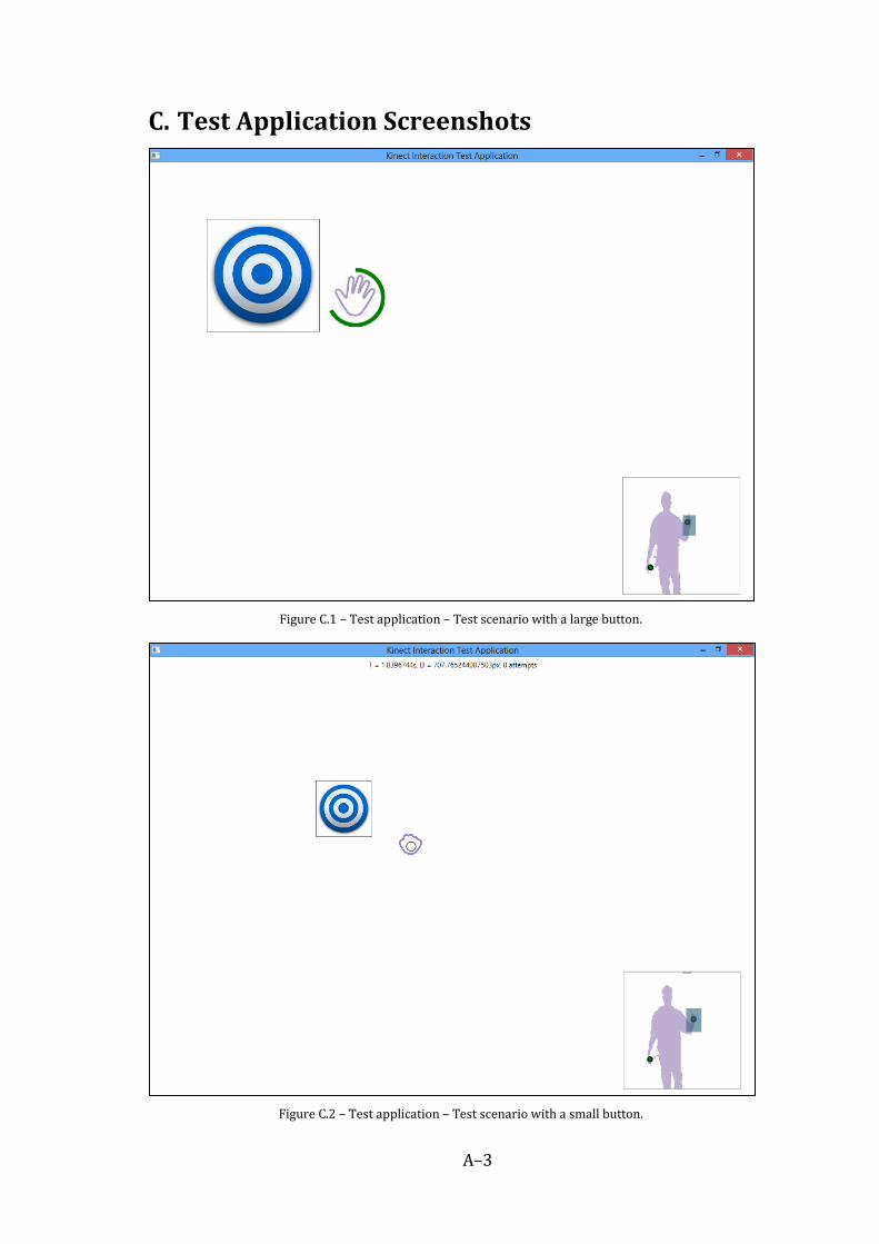
A–3
C. Test Application Screenshots
Figure C.1 – Test application – Test scenario with a large button.
Figure C.2 – Test application – Test scenario with a small button.

A–4
Figure C.3 – Test application – Test scenario for dragging objects from the window’s corners to the center of
the screen.
Figure C.4 – Test application – Test scenario for dragging objects from the center of the screen into the
window’s corners.

A–5
Figure C.5 – Test application – Test scenario with a list box.
Figure C.6 – Test application – Test scenario with a multi–touch maps.

A–6
D. Windows 8 Touch–less Application Screenshots
Figure D.1 – Window 8 Touch–less Application – Multi–touch integration with Windows 8 UI.
Figure D.2 – Window 8 Touch–less Application – Using touch–less with Web Browser.

A–7
E. A Form for User Subjective Tests