Embed Size (px)
Citation preview

Using Motion Analyzer V4.73

UUUsssiiinnnggg MMMoootttiiiooonnn AAAnnnaaalllyyyzzzeeerrr::: HHHaaannndddsss---OOOnnn LLLaaabbb
TTTrrraaaiiinnniiinnnggg LLLaaabbb MMMaaannnuuuaaalll

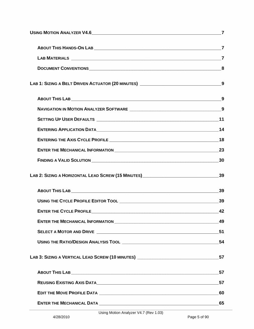
USING MOTION ANALYZER V4.6___________________________________________________7
ABOUT THIS HANDS-ON LAB __________________________________________________7
LAB MATERIALS ___________________________________________________________7
DOCUMENT CONVENTIONS____________________________________________________8
LAB 1: SIZING A BELT DRIVEN ACTUATOR (20 MINUTES) ________________________________9
ABOUT THIS LAB ___________________________________________________________9
NAVIGATION IN MOTION ANALYZER SOFTWARE ____________________________________9
SETTING UP USER DEFAULTS ________________________________________________11
ENTERING APPLICATION DATA________________________________________________14
ENTERING THE AXIS CYCLE PROFILE ___________________________________________18
ENTER THE MECHANICAL INFORMATION _________________________________________23
FINDING A VALID SOLUTION __________________________________________________30
LAB 2: SIZING A HORIZONTAL LEAD SCREW (15 MINUTES)______________________________39
ABOUT THIS LAB __________________________________________________________39
USING THE CYCLE PROFILE EDITOR TOOL _______________________________________39
ENTER THE CYCLE PROFILE__________________________________________________42
ENTER THE MECHANICAL INFORMATION _________________________________________49
SELECT A MOTOR AND DRIVE ________________________________________________51
USING THE RATIO/DESIGN ANALYSIS TOOL ______________________________________54
LAB 3: SIZING A VERTICAL LEAD SCREW (10 MINUTES) ________________________________57
ABOUT THIS LAB __________________________________________________________57
REUSING EXISTING AXIS DATA________________________________________________57
EDIT THE MOVE PROFILE DATA _______________________________________________60
ENTER THE MECHANICAL DATA _______________________________________________65
Using Motion Analyzer V4.7 (Rev 1.03) 4/28/2010 Page 5 of 90

SELECT THE MOTOR AND DRIVE ______________________________________________67
ANALYZE THE SYSTEM SHUNT REQUIREMENTS ___________________________________69
EXTRA TASK: USING MOTION SELECTOR (20 MINUTES) ________________________________73
ABOUT THIS LAB__________________________________________________________73
OPEN MOTION SELECTOR ___________________________________________________73
SELECT MOTION ITEMS FOR THE BELT INDEXER AXIS_______________________________76
SELECT MOTION ITEMS FOR THE BELT INDEXER AXIS_______________________________76
SELECT MOTION ITEMS FOR THE VERTICAL SCREW AXIS ____________________________78
SELECT MOTION ITEMS FOR THE HORIZONTAL SCREW AXIS __________________________80
CHOOSE THE SYSTEM COMPONENTS ___________________________________________81
CHOOSE THE MOTION ACCESSORIES ___________________________________________83
VIEW THE MOTION BILL OF MATERIAL __________________________________________85
APPENDIX A: DRIVE PEAK TORQUE ENHANCEMENTS __________________________________87
ABOUT THIS APPENDIX _____________________________________________________87
LOCATING THE REQUIRED TOOLS _____________________________________________87
LAB SUMMARY ___________________________________________________________90
Using Motion Analyzer V4.7 (Rev 1.03) 4/28/2010 Page 6 of 90
Using Motion Analyzer V4.73
About This Hands-On Lab
This lab introduces you to Rockwell Automation’s motion sizing and system analysis software, Motion Analyzer. The software allows you to enter information about the moving axes of your machine (the load and the actuator that is moving it) as well as your required move or cycle profile in order to select the appropriate servo motor and drive combination. SolidWorks users can import their system models directly, without having to recreate them in Motion Analyzer. Motion Analyzer additionally allows machine designers to optimize their machine design using advanced analysis tools.
You will enter the information for (3) common types of mechanical actuators and search for a valid motor and drive combination for each. The following sections explain what you’ll be doing in this lab session, and what you will need to do to complete the hands-on exercises.
What You Will Accomplish In This Lab
As you complete the exercises in this hands-on session, you will:
Learn how to use Motion Analyzer software
Learn what type of information is required by the software
Gain exposure to the advanced analysis and optimization tools in Motion Analyzer
Who Should Complete This Lab
This hands-on lab is intended for individuals who:
Would like to learn more about sizing motion systems
Would like to learn more about using Motion Analyzer software
Lab Materials
For this Hands-On lab, we have provided you with the following materials that will allow you to complete the labs in this workbook.
Hardware
This hands-on lab uses no hardware.
Software
This hands-on lab uses the following software:
Motion Analyzer V4.6 (available for download at www.ab.com/motion)
OPTIONAL: Motion Selector V4.5.1 (also available for download at www.ab.com/motion)
Lab Files This hands-on lab requires no additional files.
A “Motion Application Data Checklist” document is provided for reference. Print this file to gather the required information for each axis of motion and use it when working with Motion Analyzer on your next motion system.
Using Motion Analyzer V4.7 (Rev 1.03) 4/28/2010 Page 7 of 90
Document Conventions
Throughout this workbook, we have used the following conventions to help guide you through the lab materials.
This style or symbol: Indicates: Words shown in bold italics (e.g., RSLogix 5000 or OK)
Any item or button that you must click on, or a menu name from which you must choose an option or command. This will be an actual name of an item that you see on your screen or in an example.
Words shown in bold italics, enclosed in single quotes (e.g., 'Controller1')
An item that you must type in the specified field. This is information that you must supply based on your application (e.g., a variable).
Note: When you type the text in the field, remember that you do not need to type the quotes; simply type the words that are contained within them (e.g., Controller1).
The text that appears inside of this gray box is supplemental information regarding the lab materials, but not information that is required reading in order for you to complete the lab exercises. The text that follows this symbol may provide you with helpful hints that can make it easier for you to use this product. Most often, authors use this “Tip Text” style for important information they want their students to see.
Note: If the mouse button is not specified in the text, you should click on the left mouse button.
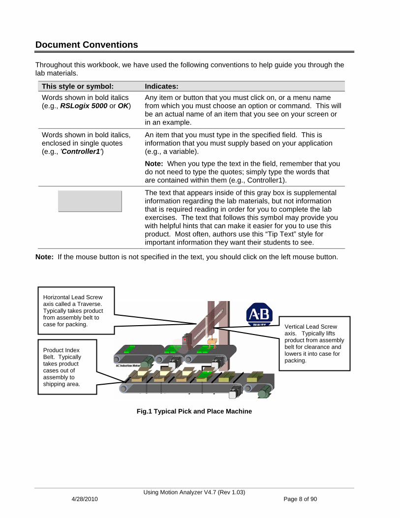
Horizontal Lead Screw axis called a Traverse. Typically takes product from assembly belt to case for packing. Vertical Lead Screw
axis. Typically lifts product from assembly belt for clearance and lowers it into case for packing.
Product Index Belt. Typically takes product cases out of assembly to shipping area.
Fig.1 Typical Pick and Place Machine
Using Motion Analyzer V4.7 (Rev 1.03) 4/28/2010 Page 8 of 90

Lab 1: Sizing a Belt Driven Actuator (20 minutes) This lab session addresses the sizing and selection of (3) different axes of motion:
A belt driven indexing conveyor
A horizontal lead screw actuator
A vertical lead screw actuator
A Pick and Place machine example (see Fig. 1) will be the source of data for each of the labs. Pick and Place machines are used in the consumer products industry for a wide variety of product transfer applications. The machine typically takes a product or products from machines such as wrappers, cartoners or fillers, and places them into a case, which then is ready for palletizing or shipment.
About This Lab
In this lab, you will use Motion Analyzer to select a servo motor and drive for the Pick and Place machine’s Product Index Belt. You will:
Learn how to navigate in Motion Analyzer software
Setup Motion Analyzer’s default values to suit your needs
Create a new application
Enter the required data for the Product Index Belt application
Follow the steps below to complete Lab Section 1.
Navigation in Motion Analyzer Software
1. Open Motion Analyzer sizing software by double-clicking on the desktop shortcut, or by selecting Start > Programs > Rockwell Automation > Motion Analyzer > Motion Analyzer.
Using Motion Analyzer V4.7 (Rev 1.03) 4/28/2010 Page 9 of 90
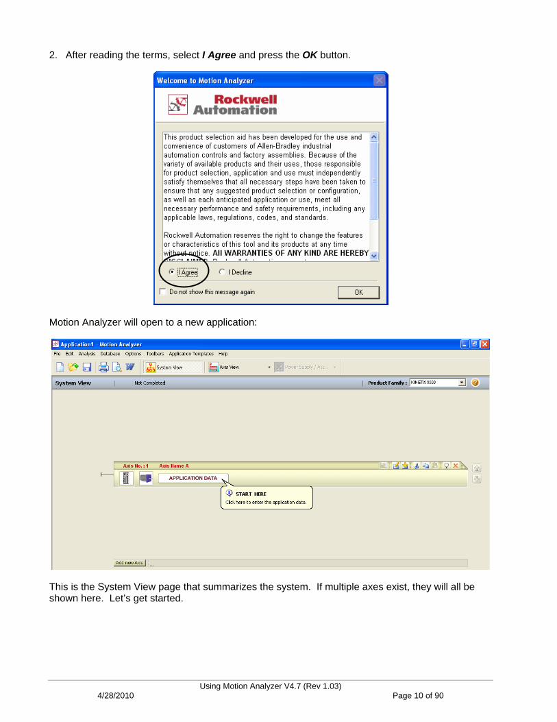
2. After reading the terms, select I Agree and press the OK button.
Motion Analyzer will open to a new application:
This is the System View page that summarizes the system. If multiple axes exist, they will all be shown here. Let’s get started.
Using Motion Analyzer V4.7 (Rev 1.03) 4/28/2010 Page 10 of 90

Setting Up User Defaults
3. From the top menu, select Options > Units of Measure.
4. Change the selection to Metric and check the box to Make the selected units the Default Setting, if desired. Press OK to save and exit.
Most mechanical actuator vendors conduct business in metric units.
Using Motion Analyzer V4.7 (Rev 1.03) 4/28/2010 Page 11 of 90

5. From the top menu again, select Options > Operating Limits. Press OK to save and exit.
The automatic selection process is affected by the limits entered in this table. Each of the motor/amplifier/gearbox variables listed in the table is a percentage of the rated values listed. The idea here is to choose operating limits based on the reliability of the data that is entered. Think of this page or table as a safety factor when selecting a combination. Keep the numbers as shown.
6. Press Cancel to exit without changes.
If entered data (load, transmission, profile and environment information) is absolutely reliable, these limits could all be set to 100% utilization but we all know that some information may not be totally accurate or we may encounter some unknowns during the implementation of the application.
“Peak Velocity” and “Bus Volts” are the most easily defined so keep these numbers at 90% or higher.
“Peak Torque”, “Peak Current” and “Average Current” are less reliable so keep these numbers at 80%.
“Winding Temperature” is the most sensitive to errors so 80 % would be normal.
7. From the top menu again, select Options > User Information.
Using Motion Analyzer V4.7 (Rev 1.03) 4/28/2010 Page 12 of 90
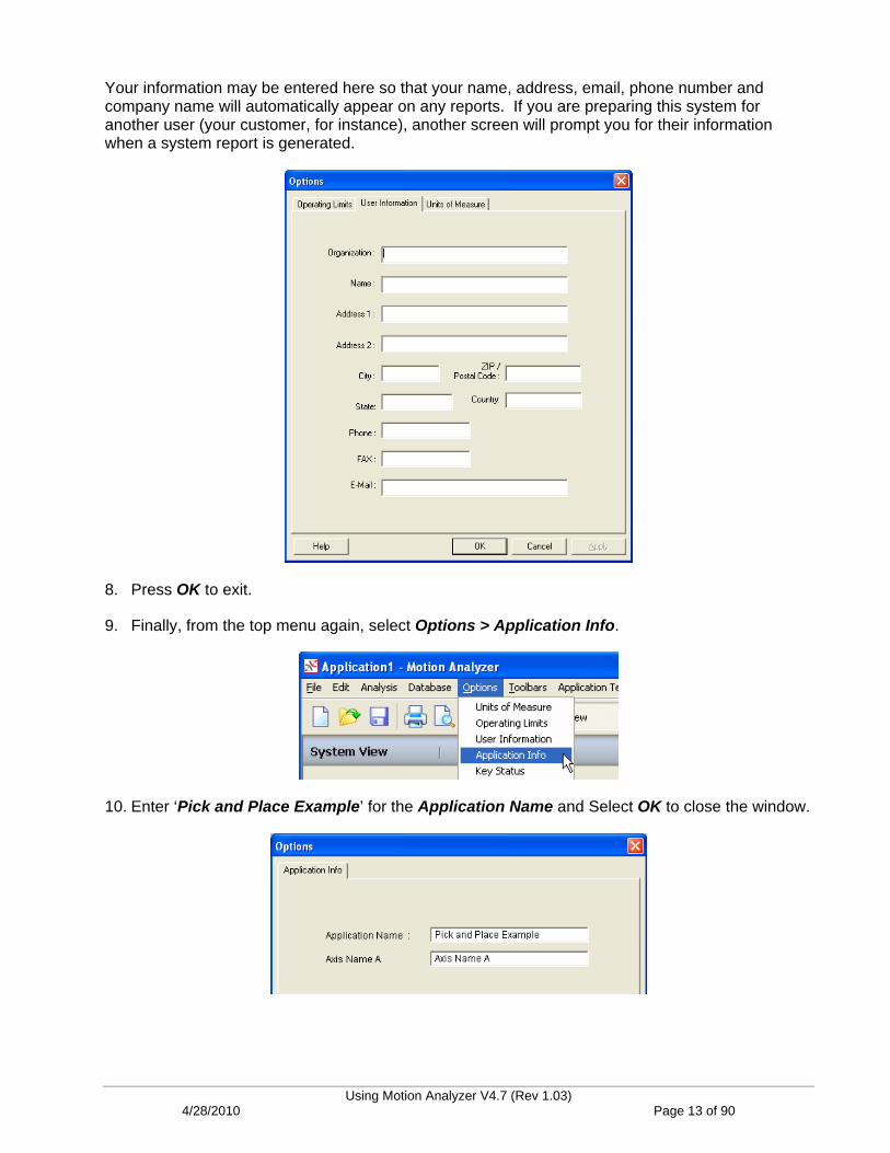
Your information may be entered here so that your name, address, email, phone number and company name will automatically appear on any reports. If you are preparing this system for another user (your customer, for instance), another screen will prompt you for their information when a system report is generated.
8. Press OK to exit.
9. Finally, from the top menu again, select Options > Application Info.
10. Enter ‘Pick and Place Example’ for the Application Name and Select OK to close the window.
Using Motion Analyzer V4.7 (Rev 1.03) 4/28/2010 Page 13 of 90
Entering Application Data
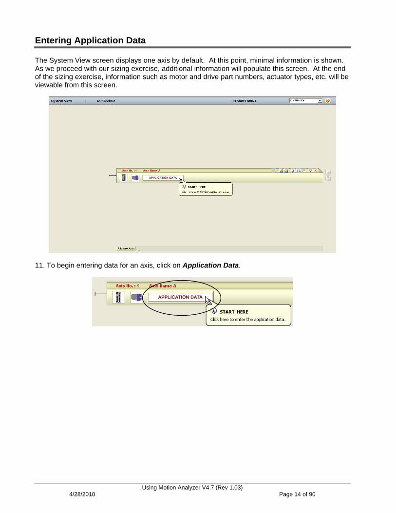
The System View screen displays one axis by default. At this point, minimal information is shown. As we proceed with our sizing exercise, additional information will populate this screen. At the end of the sizing exercise, information such as motor and drive part numbers, actuator types, etc. will be viewable from this screen.
11. To begin entering data for an axis, click on Application Data.
Using Motion Analyzer V4.7 (Rev 1.03) 4/28/2010 Page 14 of 90

The Axis Data page displays basic setup options for the axis.
On this page, you choose whether your axis is linear or rotary, and whether the axis is built from user-provided components or one of Rockwell Automation’s MP-Series Integrated Linear Stages. The voltage (or range of voltages) that will be provided to the drives is defined here, and you can enter a typical ambient temperature or altitude for the motor’s operating environment. If your axis requires a (factory only) holding brake, you can make this selection here. Finally, this is where you can give the axis a meaningful name.
12. At the bottom of the screen, click on the area marked System Notes.
This is where you can enter important information about the system, or keep track of assumptions that were made in the sizing process. This data will be printed on the system report and it will remind you that these assumptions need verified.
It is quite common for data to be missing or unavailable during this process.
Using Motion Analyzer V4.7 (Rev 1.03) 4/28/2010 Page 15 of 90

Let’s get started entering information about the belt indexer axis.
There are (7) steps to sizing a motion application in Motion Analyzer. They are:
(1) Specify load type (linear or rotary)
(2) Determine application preferences
(3) Specify the machine’s cycle profile, or worst case move
(4) Specify actuator type
(5) Specify transmission stage(s)
(6) Search for a suitable motor/drive combination for the application
(7) Select shunt (if required) and system module (for Kinetix 2000/6000 drives)
Let’s follow the (7) steps outlined above to enter our application data.
Here is the data that was provided for the belt indexer axis:
Package weight (i.e. total weight on belt at any one time) = 3 kg Belt Actuator:
Belt Weight = 2 kg
Drive Rolls, Quantity (2):
100mm diameter (about 4”)
600mm long (about 24”)
Rolled Steel
Motor Coupling Moment of Inertia = 2.6g-cm^2
Move 250mm (about 10”) in 1 sec. and dwell for 1 sec.
Plant operates at 460Vac with an ambient temp of 30 degrees (C)
Using Motion Analyzer V4.7 (Rev 1.03) 4/28/2010 Page 16 of 90

13. Some additional system information provided by the customer is that the plant has 460Vac and the system operates in a ‘30’ (degree C) environment. On the Axis Setup tab, fill in the data for the ‘Belt Indexer‘ axis as shown below.
The tabs across the top lead you through entering the required data. The green check mark means that you have completed a tab and the red “x” indicates that more data is needed.
Using Motion Analyzer V4.7 (Rev 1.03) 4/28/2010 Page 17 of 90
Entering the Axis Cycle Profile
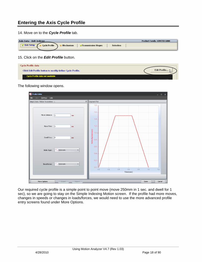
14. Move on to the Cycle Profile tab.
15. Click on the Edit Profile button.
The following window opens.
Our required cycle profile is a simple point to point move (move 250mm in 1 sec. and dwell for 1 sec), so we are going to stay on the Simple Indexing Motion screen. If the profile had more moves, changes in speeds or changes in loads/forces, we would need to use the more advanced profile entry screens found under More Options.
Using Motion Analyzer V4.7 (Rev 1.03) 4/28/2010 Page 18 of 90
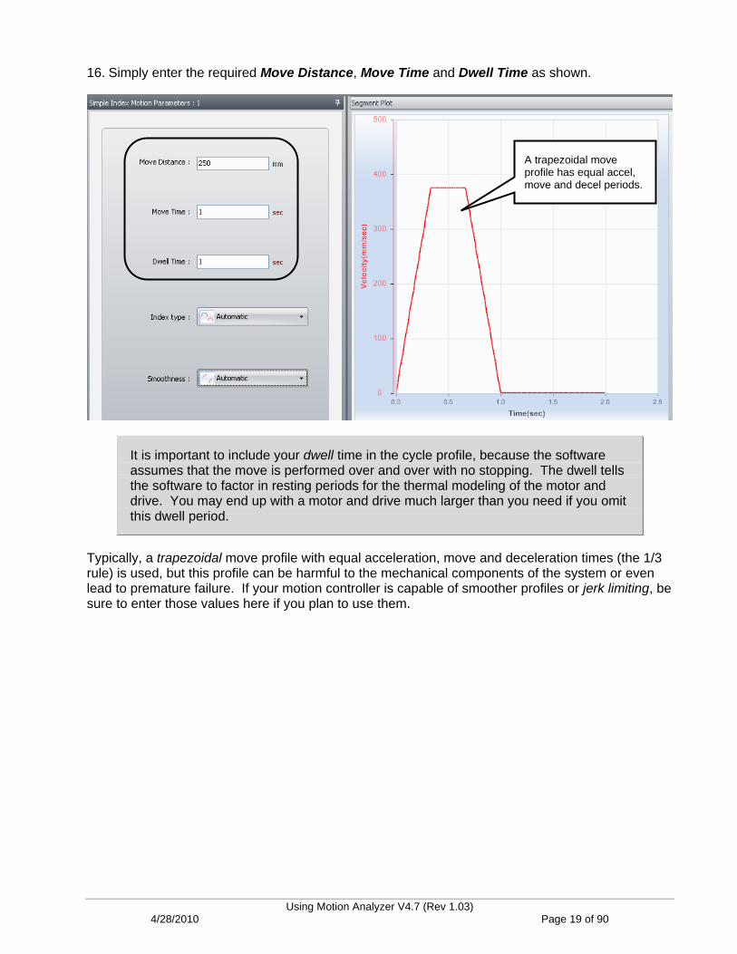
16. Simply enter the required Move Distance, Move Time and Dwell Time as shown.
A trapezoidal move profile has equal accel, move and decel periods.
It is important to include your dwell time in the cycle profile, because the software assumes that the move is performed over and over with no stopping. The dwell tells the software to factor in resting periods for the thermal modeling of the motor and drive. You may end up with a motor and drive much larger than you need if you omit this dwell period.
Typically, a trapezoidal move profile with equal acceleration, move and deceleration times (the 1/3 rule) is used, but this profile can be harmful to the mechanical components of the system or even lead to premature failure. If your motion controller is capable of smoother profiles or jerk limiting, be sure to enter those values here if you plan to use them.
Using Motion Analyzer V4.7 (Rev 1.03) 4/28/2010 Page 19 of 90

Pure S-Curve profiles limit acceleration for 100% of the time and a Trapezoidal profile for 0% of the time. Studies have shown that the best compromise between move speed and smoothness is simply 50% jerk limitation (50% of overall accel or decel time).
Trapezoidal Profile S-Curve Profile
Smoother move profiles require higher motor speeds and higher motor torques in order to complete in the same amount of time. Failure to enter this profile here could
lead to a motor being chosen that is not capable of the required speed or torque.
17. Click on More Options to specify our move profile parameters.
Using Motion Analyzer V4.7 (Rev 1.03) 4/28/2010 Page 20 of 90
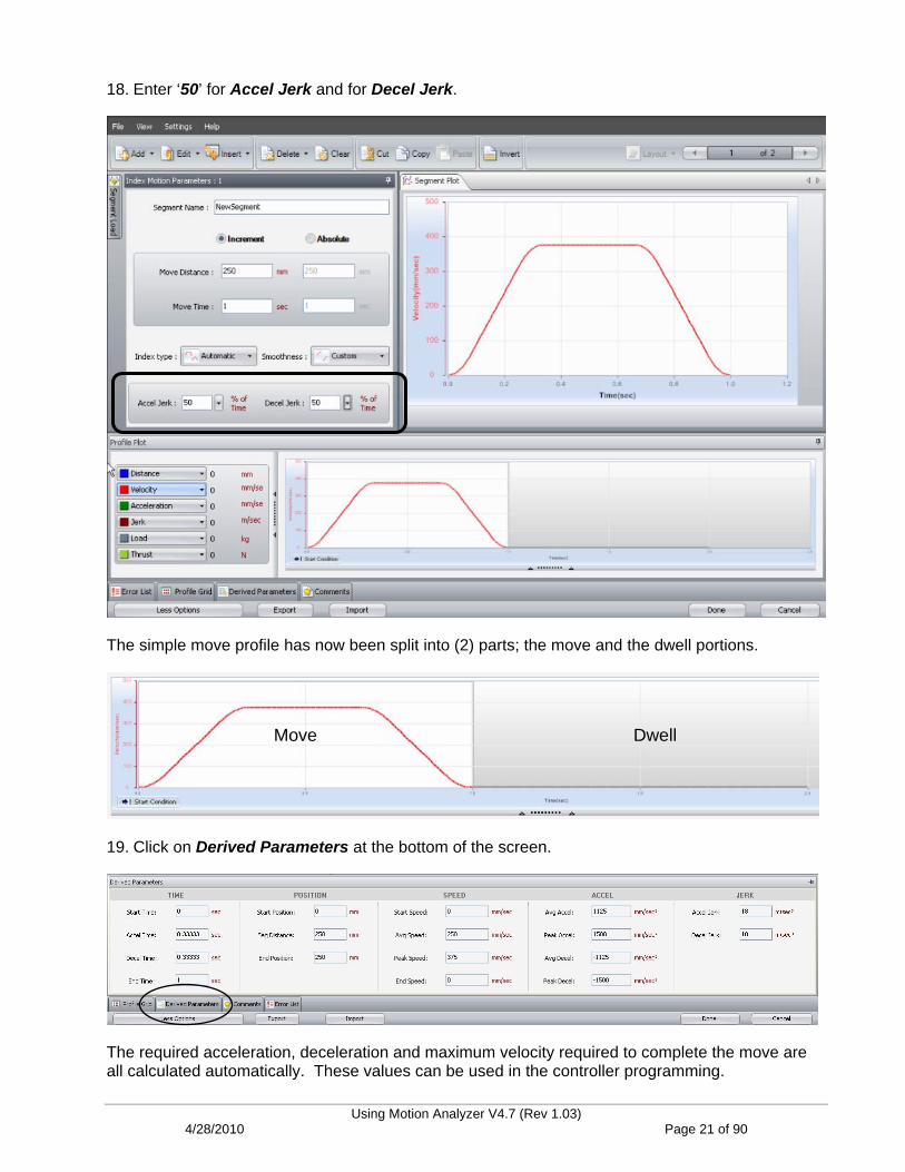
18. Enter ‘50’ for Accel Jerk and for Decel Jerk.
The simple move profile has now been split into (2) parts; the move and the dwell portions.
Move Dwell
19. Click on Derived Parameters at the bottom of the screen.
The required acceleration, deceleration and maximum velocity required to complete the move are all calculated automatically. These values can be used in the controller programming.
Using Motion Analyzer V4.7 (Rev 1.03) 4/28/2010 Page 21 of 90

20. Click on Comments at the bottom of the screen.
There are places to makes notes on the overall cycle profile or even every individual segment.
There are many more advanced features and functions provided by the enhanced profile editor. We will explore more of these throughout the remaining chapters of
this lab.
21. Press Done when complete.
The Cycle Profile should appear as shown.
Using Motion Analyzer V4.7 (Rev 1.03) 4/28/2010 Page 22 of 90

Enter the Mechanical Information
22. Click on the Mechanism tab to continue.
23. Locate the Load Data section. Using our axis data, enter a Mass of ’3’ kg to account for the weight of the packages on the belt. Since our drive rolls are typically made with roller bearings, we can use the Coefficient of Friction for a Ball Slide, which is listed as ‘0.01.’ You should add this to your list of items to be verified in the System Notes if you are not sure. Leave the Inclination angle at (0) degrees since we’re working with a horizontal axis.
This tab also includes extremely helpful diagrams of the different types of actuators supported by Motion Analyzer. The actuators are selected from the pull down menu for Actuator Type. Notice how the input parameters and the diagram change for each type of actuator. Helpful values for terms like coefficient of friction are included as well.
Using Motion Analyzer V4.7 (Rev 1.03) 4/28/2010 Page 23 of 90
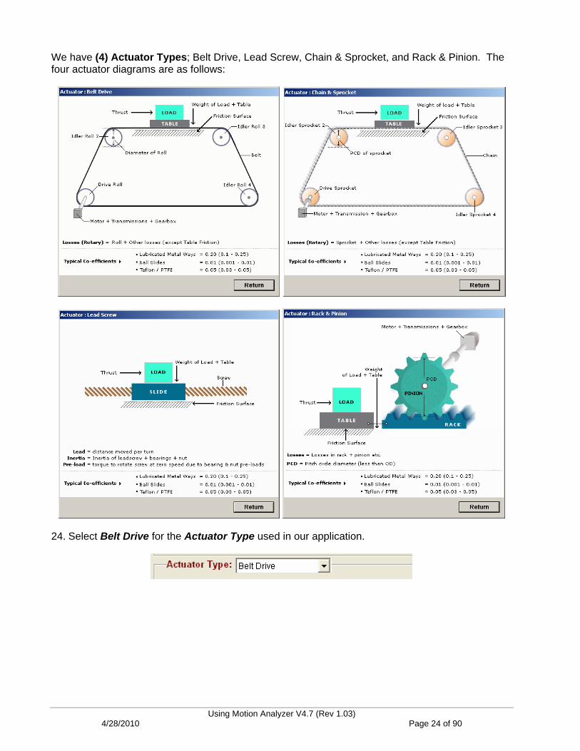
We have (4) Actuator Types; Belt Drive, Lead Screw, Chain & Sprocket, and Rack & Pinion. The four actuator diagrams are as follows:
24. Select Belt Drive for the Actuator Type used in our application.
Using Motion Analyzer V4.7 (Rev 1.03) 4/28/2010 Page 24 of 90
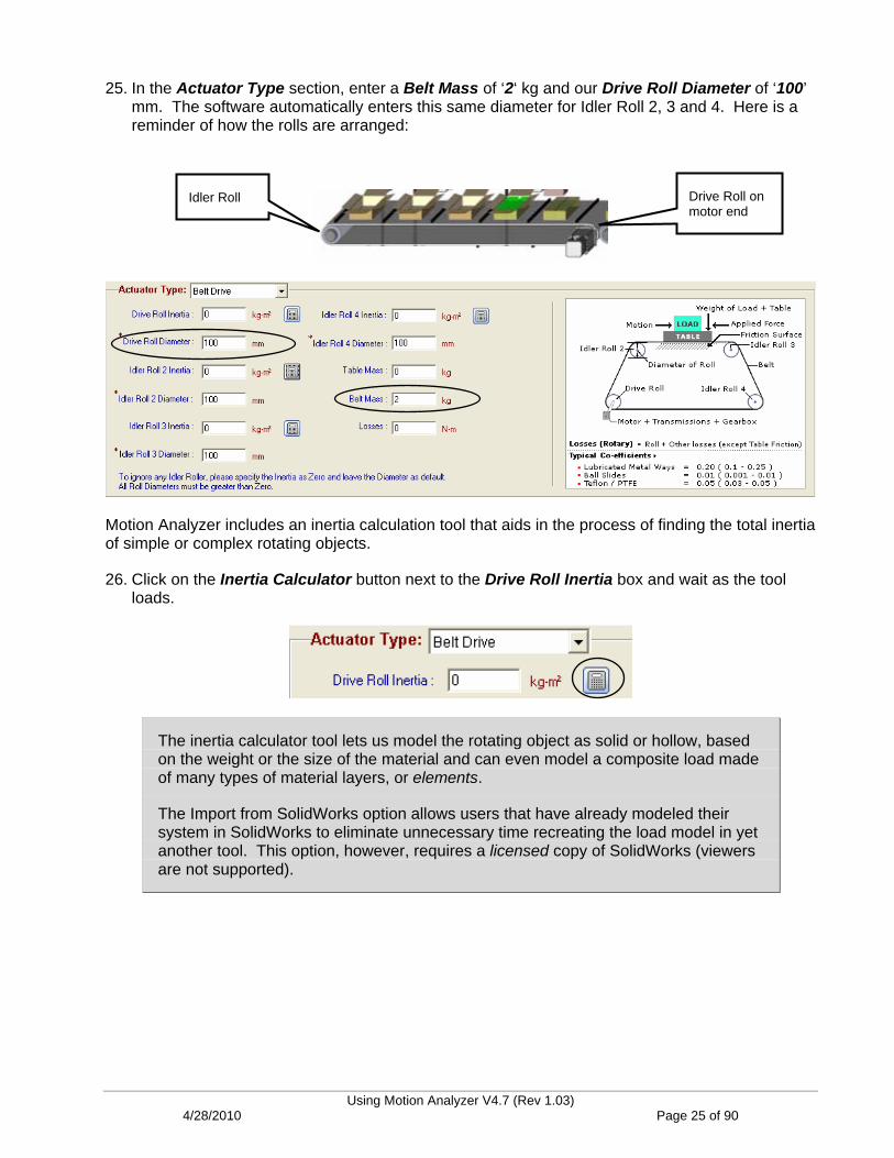
25. In the Actuator Type section, enter a Belt Mass of ‘2‘ kg and our Drive Roll Diameter of ‘100’ mm. The software automatically enters this same diameter for Idler Roll 2, 3 and 4. Here is a reminder of how the rolls are arranged:
Drive Roll on motor end
Idler Roll
Motion Analyzer includes an inertia calculation tool that aids in the process of finding the total inertia of simple or complex rotating objects.
26. Click on the Inertia Calculator button next to the Drive Roll Inertia box and wait as the tool loads.
The inertia calculator tool lets us model the rotating object as solid or hollow, based on the weight or the size of the material and can even model a composite load made of many types of material layers, or elements.
The Import from SolidWorks option allows users that have already modeled their system in SolidWorks to eliminate unnecessary time recreating the load model in yet another tool. This option, however, requires a licensed copy of SolidWorks (viewers are not supported).
Using Motion Analyzer V4.7 (Rev 1.03) 4/28/2010 Page 25 of 90
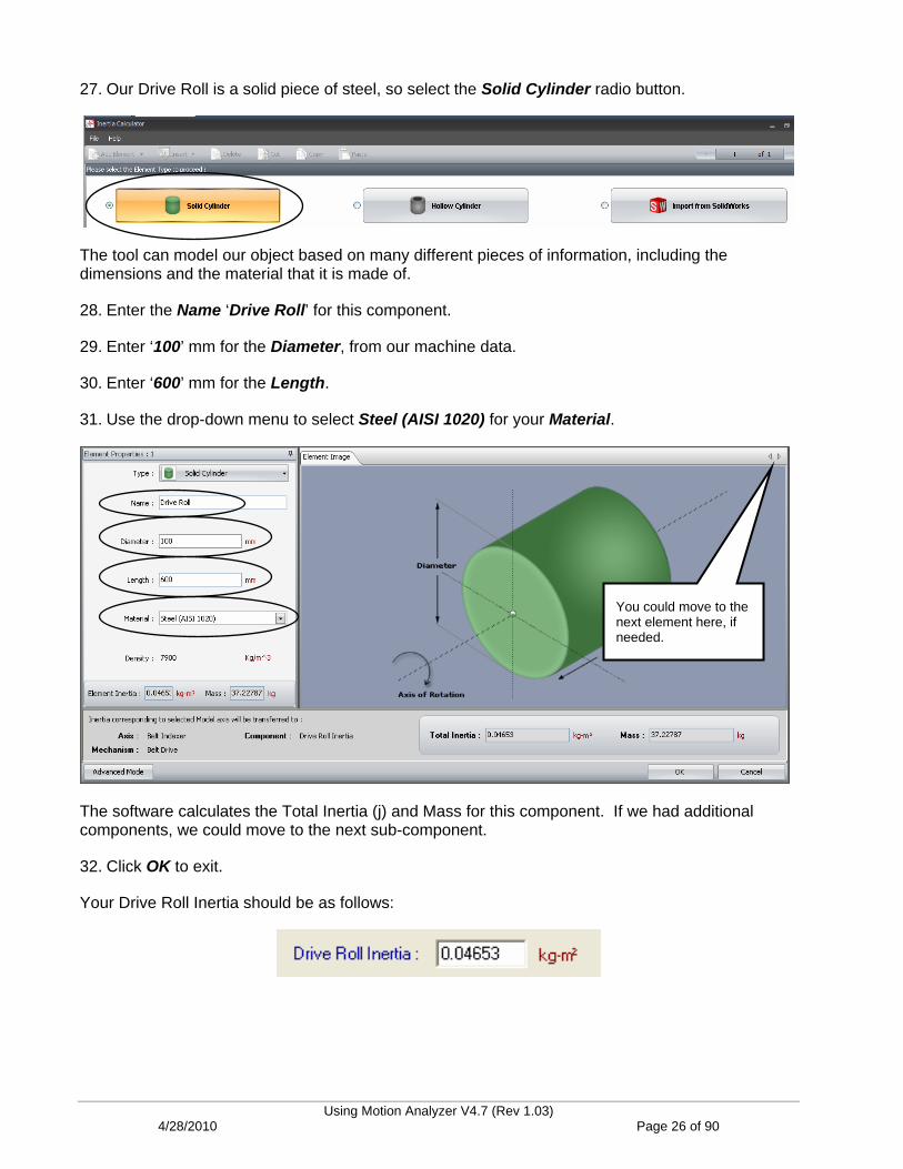
27. Our Drive Roll is a solid piece of steel, so select the Solid Cylinder radio button.
The tool can model our object based on many different pieces of information, including the dimensions and the material that it is made of.
28. Enter the Name ‘Drive Roll’ for this component.
29. Enter ‘100’ mm for the Diameter, from our machine data.
30. Enter ‘600’ mm for the Length.
31. Use the drop-down menu to select Steel (AISI 1020) for your Material.
You could move to the next element here, if needed.
The software calculates the Total Inertia (j) and Mass for this component. If we had additional components, we could move to the next sub-component.
32. Click OK to exit.
Your Drive Roll Inertia should be as follows:
Using Motion Analyzer V4.7 (Rev 1.03) 4/28/2010 Page 26 of 90

33. Since the Drive Roll and Idler Roll are the same geometry and material, simply Copy and Paste the Drive Roll Inertia value into the Idler Roll 2 Inertia field.
You don’t need to fill in anything for the remaining idlers, since this axis only has (2) rolls. If you have more idlers than the (4) provided, note that you can simply add the inertia values together and enter the total in one of the spaces provided.
34. Your Mechanism tab should look as follows:
35. Move to the Transmission Stages tab.
Using Motion Analyzer V4.7 (Rev 1.03) 4/28/2010 Page 27 of 90

This tab allows you to enter the mechanical information for any rotating devices connected between the motor shaft and actuator. Use the drop-down menu to view the (4) available models and their associated diagram. A helpful Compute Model is also provided for each to aid in entering the required data.
36. Select a Coupling for our system, as mentioned in the machine data section.
This is published data available from the coupling manufacturer. It can be used in the Simulation feature of Motion Analyzer to model system performance.
Using Motion Analyzer V4.7 (Rev 1.03) 4/28/2010 Page 28 of 90
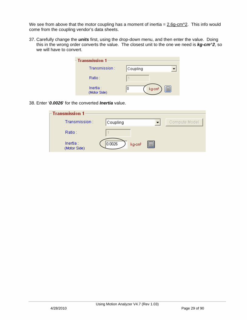
We see from above that the motor coupling has a moment of inertia = 2.6g-cm^2. This info would come from the coupling vendor’s data sheets.
37. Carefully change the units first, using the drop-down menu, and then enter the value. Doing this in the wrong order converts the value. The closest unit to the one we need is kg-cm^2, so we will have to convert.
38. Enter ‘0.0026‘ for the converted Inertia value.
Using Motion Analyzer V4.7 (Rev 1.03) 4/28/2010 Page 29 of 90

Finding a Valid Solution
39. We have finished entering the application data and now we can select a motor and drive. Move to the Selection tab.
This tab allows us to set our selection preferences.
We can specify whether to include or exclude a gearbox.
We can specify which motor families to include, even down to the frame size of the motor. By default, the MPL Series motors are chosen. These motors are fine for most applications.
40. Press the radio button to Show the Solutions within the Max Inertia Ratio (load to motor mismatch). We will exclude solutions above 10:1 in order to insure system stability. This is a concern when trying to position accurately.
Using Motion Analyzer V4.7 (Rev 1.03) 4/28/2010 Page 30 of 90
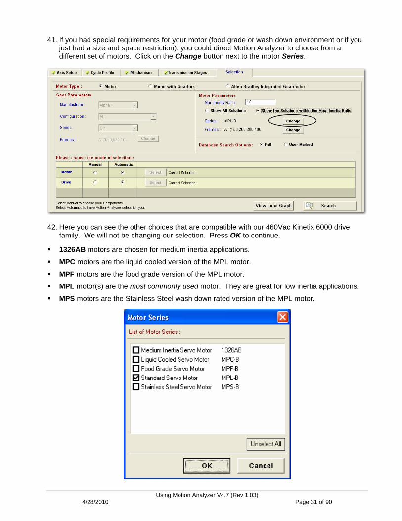
41. If you had special requirements for your motor (food grade or wash down environment or if you just had a size and space restriction), you could direct Motion Analyzer to choose from a different set of motors. Click on the Change button next to the motor Series.
42. Here you can see the other choices that are compatible with our 460Vac Kinetix 6000 drive family. We will not be changing our selection. Press OK to continue.
1326AB motors are chosen for medium inertia applications.
MPC motors are the liquid cooled version of the MPL motor.
MPF motors are the food grade version of the MPL motor.
MPL motor(s) are the most commonly used motor. They are great for low inertia applications.
MPS motors are the Stainless Steel wash down rated version of the MPL motor.
Using Motion Analyzer V4.7 (Rev 1.03) 4/28/2010 Page 31 of 90
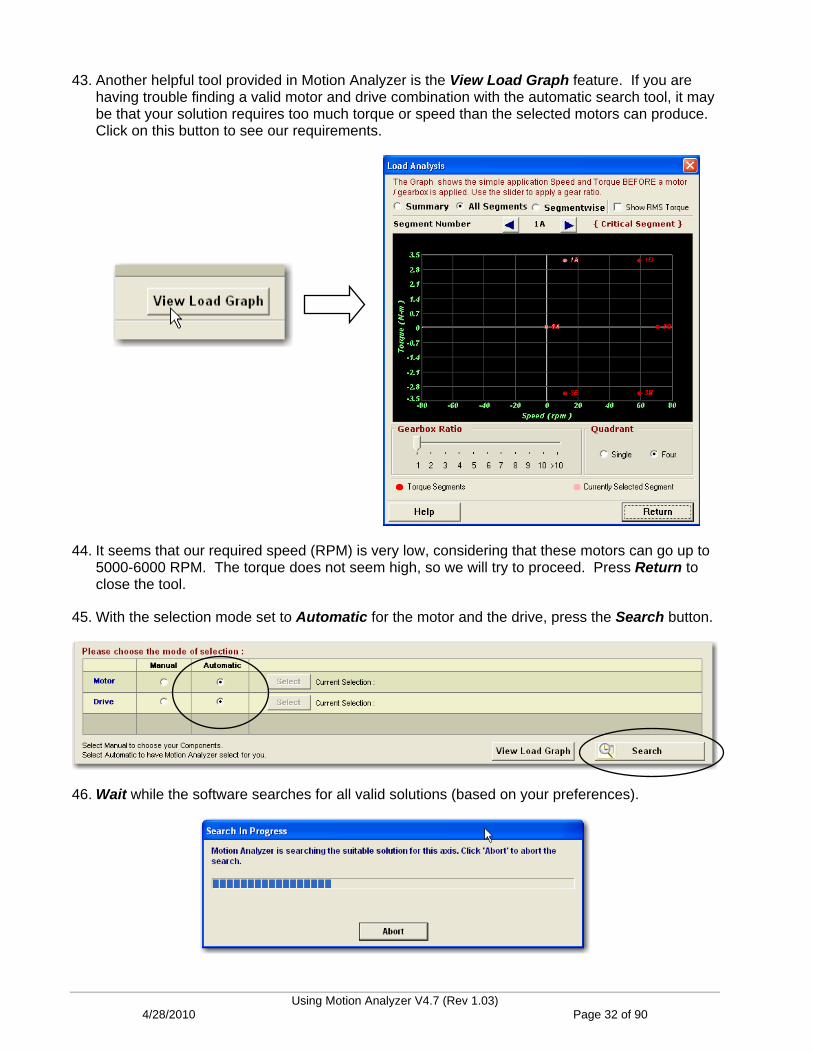
43. Another helpful tool provided in Motion Analyzer is the View Load Graph feature. If you are having trouble finding a valid motor and drive combination with the automatic search tool, it may be that your solution requires too much torque or speed than the selected motors can produce. Click on this button to see our requirements.
44. It seems that our required speed (RPM) is very low, considering that these motors can go up to 5000-6000 RPM. The torque does not seem high, so we will try to proceed. Press Return to close the tool.
45. With the selection mode set to Automatic for the motor and the drive, press the Search button.
46. Wait while the software searches for all valid solutions (based on your preferences).
Using Motion Analyzer V4.7 (Rev 1.03) 4/28/2010 Page 32 of 90

Motion Analyzer displays the list of viable motor and drive combinations. The list can be sorted in a variety of ways, based on your needs, and the color codes indicate whether a parameter exceeds your “safety margin” setting or exceeds the capacity of the product (usually when manually chosen). The motors displayed are actually quite large, due to our high inertia.
Throughout the lab, your solution list may vary, based on the last time you ran Current Updater.
47. Let’s sort our solutions by cost in ascending order. Click on the M+D Cost (motor and drive) column as shown below. 100% is defined as the highest priced solution. All of the solutions are listed as solution state value of 1 or passing (green). Slide the lower scroll bar to view the other operating parameters (or any offending values in the case of a solution state other than 1).
Using Motion Analyzer V4.7 (Rev 1.03) 4/28/2010 Page 33 of 90
First, you will only want to look at solutions with a Solution State of “1” because that indicates no criteria failed, or is within the safety margin. Then you will most likely want to pick a solution that has the best cost or inertia ratio. When you consider the inertia ratio, you ideally would like to minimize it but that is always based on how much bandwidth you really need in the application. If it is a point to point move where some overshoot can happen, you could possibly go 10:1 or less and probably be ok. If it is a high bandwidth requirement such as something that does contouring, etc., you try to match it lower, say 3:1 or less. Ideally, you try to match the motor rotor inertia to the load so that they act in unison.
If you look at the drive, you will want to make sure the peak currents/torques are below 80% since any type of loss or friction that is not accounted for may mean the difference from doing an acceleration and deceleration. Motion Analyzer is only as good as what you enter into it. If you look at the motor, you will want to make sure Motor Winding Temperature less than 60% to make up for losses or friction that was not accounted for.
Bus utilization of the drive is next important because if it is exceeded, then there isn’t enough DC Bus to spin the motor at the required V/1000rpm that the application needs. Peak Velocity in the motor section tells you what the motor can and can't do based on the input voltage. If the bus utilization is too high, then the motor can not make that move. Many times you need to increase the input voltage, if you can or change to a different motor winding or in the long run, change the cycle profile and/or work with the mechanics.
You can also tell a lot from the speed torque curve. If you are seeing a lot of torque required but only at very low speeds, some kind of reduction may help to improve that situation. Generally, it moves the points down and to the right because the motor generates less torque but requires much higher speed.
For motors that have a low rpm and high RMS torque, you will want to consider a gearbox.
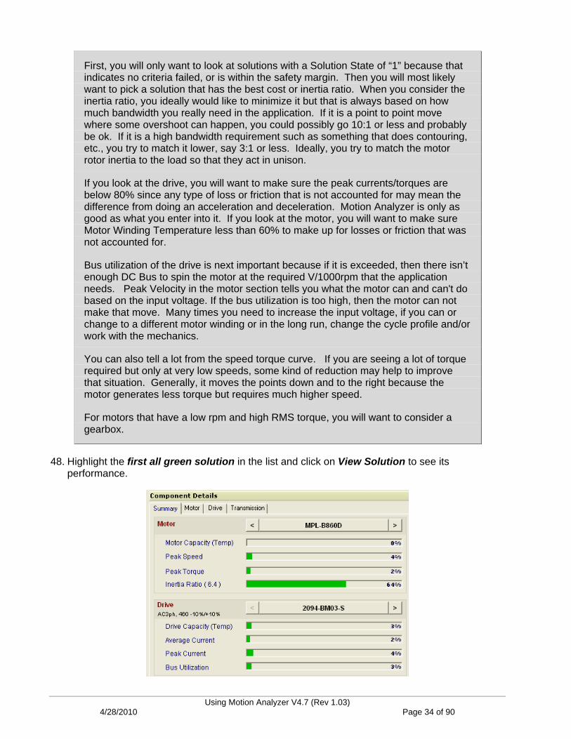
48. Highlight the first all green solution in the list and click on View Solution to see its performance.
Using Motion Analyzer V4.7 (Rev 1.03) 4/28/2010 Page 34 of 90
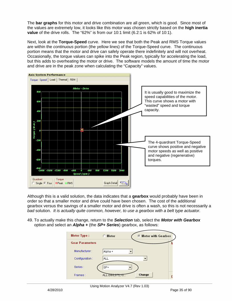
The bar graphs for this motor and drive combination are all green, which is good. Since most of the values are extremely low, it looks like this motor was chosen strictly based on the high inertia value of the drive rolls. The “62%” is from our 10:1 limit (6.2:1 is 62% of 10:1).
Next, look at the Torque-Speed curve. Here we see that both the Peak and RMS Torque values are within the continuous portion (the yellow lines) of the Torque-Speed curve. The continuous portion means that the motor and drive can safely operate there indefinitely and will not overheat. Occasionally, the torque values can spike into the Peak region, typically for accelerating the load, but this adds to overheating the motor or drive. The software models the amount of time the motor and drive are in the peak zone when calculating the “Capacity” values.
It is usually good to maximize the speed capabilities of the motor. This curve shows a motor with “wasted” speed and torque capacity.
The 4-quardrant Torque-Speed curve shows positive and negative motor speeds as well as positive and negative (regenerative) torques.
Although this is a valid solution, the data indicates that a gearbox would probably have been in order so that a smaller motor and drive could have been chosen. The cost of the additional gearbox versus the savings of a smaller motor and drive is often a wash, so this is not necessarily a bad solution. It is actually quite common, however, to use a gearbox with a belt type actuator.
49. To actually make this change, return to the Selection tab, select the Motor with Gearbox option and select an Alpha + (the SP+ Series) gearbox, as follows:
Using Motion Analyzer V4.7 (Rev 1.03) 4/28/2010 Page 35 of 90

50. Press Search and use your skills to select the best, low-cost solution in the list.
Your new lost-cost solution results might look similar to this (many possibilities are available):
A simple gearbox now allows us to use one of the smallest motors and drives available. Why? Because the high inertia of the idler rolls is reduced by the square of the gear ratio (35^2 = 1225), while the motor speed requirement only increases 1:1 with the gear ratio. Ah, physics!
There are many additional analysis tools included with Motion Analyzer, shown at the bottom of the screen. Each one helps optimize the motor and drive selection and possibly remove costs from the system.
Ratio/Design Analysis gives great insight on what the best gear ratio (or belt reduction ratio) may be, based on the motor and drive parameters.
Tolerance/Design Analysis offers the ability to examine the crucial system parameters as one system variable changes, such as line speed or product weight.
Torque Analysis and Segment Data help to investigate what aspect of the system require the most torque during a duty cycle. It is often surprising where the losses or requirements are originating.
Look for additional (advanced) labs available on these topics.
Using Motion Analyzer V4.7 (Rev 1.03) 4/28/2010 Page 36 of 90

51. Return to the System View.
Observe all of the icons that represent our selected components. Our motor, drive (and gearbox, if chosen) selection are even specified.
Drive, motor, gearbox, coupling, belt actuator and cycle profile (shown above). The yellow triangle above simple points out that the gearbox selected comes from our 3-party provider, Wittenstein, and not Rockwell Automation.
52. Be sure to Save your work. Confirm any prompts and choose a location to save your file.
Using Motion Analyzer V4.7 (Rev 1.03) 4/28/2010 Page 37 of 90

Lab 2: Sizing a Horizontal Lead Screw (15 Minutes)
About This Lab
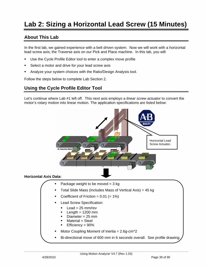
In the first lab, we gained experience with a belt driven system. Now we will work with a horizontal lead screw axis; the Traverse axis on our Pick and Place machine. In this lab, you will:
Use the Cycle Profile Editor tool to enter a complex move profile
Select a motor and drive for your lead screw axis
Analyze your system choices with the Ratio/Design Analysis tool.
Follow the steps below to complete Lab Section 2.
Using the Cycle Profile Editor Tool
Let’s continue where Lab #1 left off. This next axis employs a linear screw actuator to convert the motor’s rotary motion into linear motion. The application specifications are listed below:
Horizontal Lead Screw Actuator.
Horizontal Axis Data:
Package weight to be moved = 3 kg
Total Slide Mass (Includes Mass of Vertical Axis) = 45 kg
Coefficient of Friction = 0.01 (= 1%)
Lead Screw Specification: Lead = 25 mm/rev Length = 1200 mm Diameter = 25 mm Material = Steel Efficiency = 90%
Motor Coupling Moment of Inertia = 2.6g-cm^2
Bi-directional move of 600 mm in 6 seconds overall. See profile drawing.
Using Motion Analyzer V4.7 (Rev 1.03) 4/28/2010 Page 39 of 90
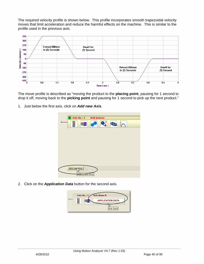
The required velocity profile is shown below. This profile incorporates smooth trapezoidal velocity moves that limit acceleration and reduce the harmful effects on the machine. This is similar to the profile used in the previous axis.
The move profile is described as “moving the product to the placing point, pausing for 1 second to drop it off, moving back to the picking point and pausing for 1 second to pick up the next product.”
1. Just below the first axis, click on Add new Axis.
2. Click on the Application Data button for the second axis.
Using Motion Analyzer V4.7 (Rev 1.03) 4/28/2010 Page 40 of 90
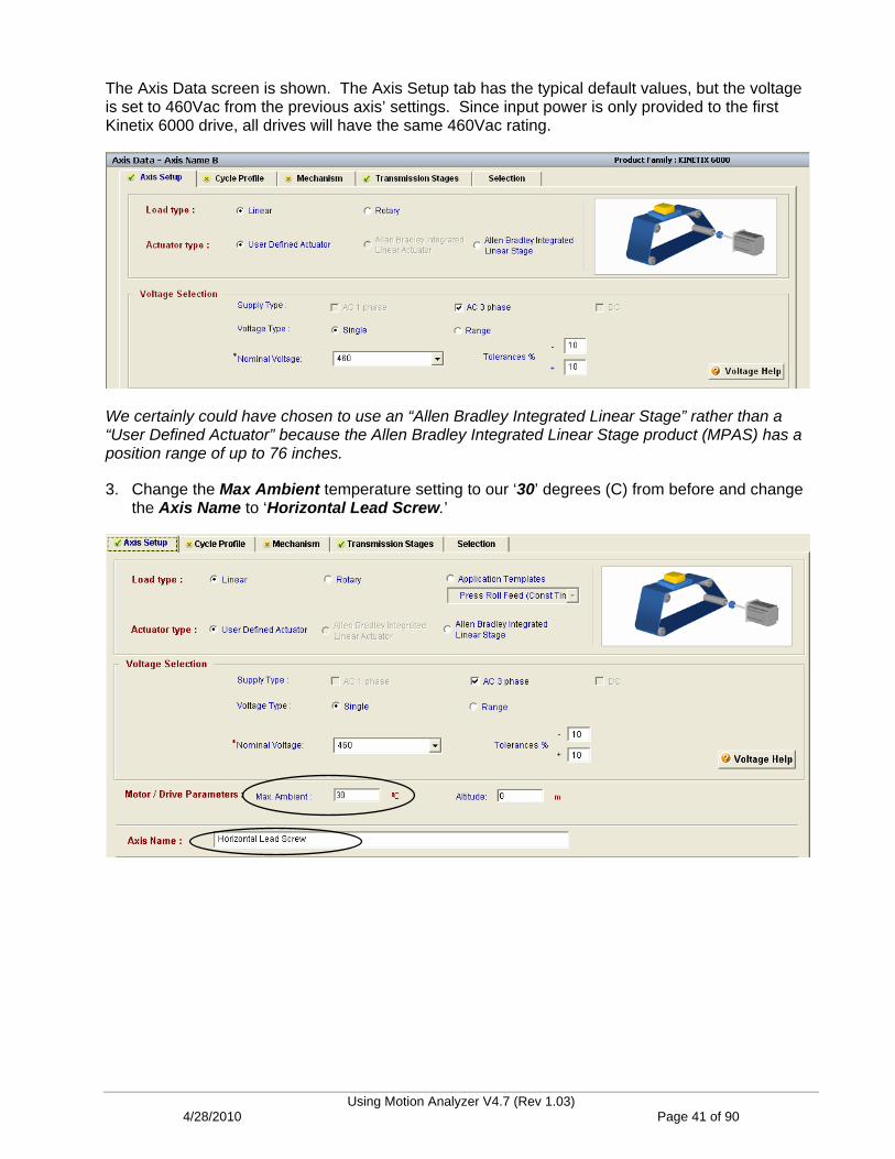
The Axis Data screen is shown. The Axis Setup tab has the typical default values, but the voltage is set to 460Vac from the previous axis’ settings. Since input power is only provided to the first Kinetix 6000 drive, all drives will have the same 460Vac rating.
We certainly could have chosen to use an “Allen Bradley Integrated Linear Stage” rather than a “User Defined Actuator” because the Allen Bradley Integrated Linear Stage product (MPAS) has a position range of up to 76 inches.
3. Change the Max Ambient temperature setting to our ‘30’ degrees (C) from before and change the Axis Name to ‘Horizontal Lead Screw.’
Using Motion Analyzer V4.7 (Rev 1.03) 4/28/2010 Page 41 of 90

Enter the Cycle Profile
4. Move to the Cycle Profile tab.
5. Click on the Edit Profile button.
Since this move profile consists of more than one simple point to point move, we will need to use a more advanced profile editor. Here is the required move profile, segment by segment:
Let’s enter the first (2) segments using the Simple Index editor.
6. As we did before, enter a Move Distance of ‘600’ mm.
7. Enter a Move Time of ‘2’seconds.
8. Enter a Dwell Time of ‘1’ second.
Using Motion Analyzer V4.7 (Rev 1.03) 4/28/2010 Page 42 of 90
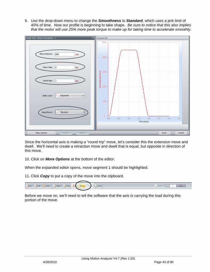
9. Use the drop-down menu to change the Smoothness to Standard, which uses a jerk limit of 40% of time. Now our profile is beginning to take shape. Be sure to notice that this also implies that the motor will use 25% more peak torque to make up for taking time to accelerate smoothly.
Since the horizontal axis is making a “round trip” move, let’s consider this the extension move and dwell. We’ll need to create a retraction move and dwell that is equal, but opposite in direction of this move.
10. Click on More Options at the bottom of the editor.
When the expanded editor opens, move segment 1 should be highlighted.
11. Click Copy to put a copy of the move into the clipboard.
Before we move on, we’ll need to tell the software that the axis is carrying the load during this portion of the move.
Using Motion Analyzer V4.7 (Rev 1.03) 4/28/2010 Page 43 of 90

12. Click on the Segment Load tab on the side of the editor and add our ‘3’ kg Payload Mass to the profile.
We could also apply any external forces here as well.
13. Click the > right navigation arrow to move to the next move segment.
Technically, the payload is still in place for this portion of the move, so we’ll add it. This is much more important to consider when sizing a vertical axis which is always overcoming gravity.
14. Click on the Segment Load tab again and add our ‘3’ kg Payload Mass to the profile.
Using Motion Analyzer V4.7 (Rev 1.03) 4/28/2010 Page 44 of 90
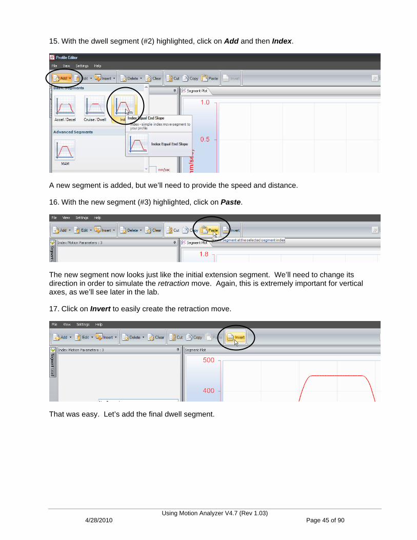
15. With the dwell segment (#2) highlighted, click on Add and then Index.
A new segment is added, but we’ll need to provide the speed and distance.
16. With the new segment (#3) highlighted, click on Paste.
The new segment now looks just like the initial extension segment. We’ll need to change its direction in order to simulate the retraction move. Again, this is extremely important for vertical axes, as we’ll see later in the lab.
17. Click on Invert to easily create the retraction move.
That was easy. Let’s add the final dwell segment.
Using Motion Analyzer V4.7 (Rev 1.03) 4/28/2010 Page 45 of 90

18. With segment (#3) highlighted, click Add and then Dwell.
19. Change the dwell Time to ‘1’ sec.
20. You can confirm your payload by clicking on Load in the lower left area of the editor. The line indicates that the load is indeed present for segments 1 and 2, but then removed for segments 3 and 4.
Experienced Motion Analyzer users may notice a lot of new enhancements to the profile editor, beginning in V4.6.
The load is removed.
Using Motion Analyzer V4.7 (Rev 1.03) 4/28/2010 Page 46 of 90

21. Next, click Export at the bottom of the editor.
Motion Analyzer saves you time and money on your development by allowing you to easily export your cycle profile where it is actually needed; in the motion controller’s
application program.
22. Click Next to see more options for exporting.
New for version 4.6, users can eliminate the task of having to recreate the motion profile in the motion controller by simply pasting it into their Logix motion application code or into SolidWorks for program simulation.
Using Motion Analyzer V4.7 (Rev 1.03) 4/28/2010 Page 47 of 90
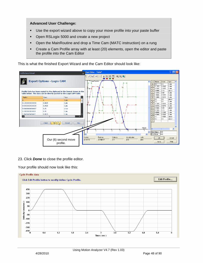
Advanced User Challenge:
Use the export wizard above to copy your move profile into your paste buffer
Open RSLogix 5000 and create a new project
Open the MainRoutine and drop a Time Cam (MATC instruction) on a rung
Create a Cam Profile array with at least (20) elements, open the editor and paste the profile into the Cam Editor
This is what the finished Export Wizard and the Cam Editor should look like:
Our (6) second move
profile.
23. Click Done to close the profile editor.
Your profile should now look like this:
Using Motion Analyzer V4.7 (Rev 1.03) 4/28/2010 Page 48 of 90

Enter the Mechanical Information
24. Move to the Mechanism tab.
25. Enter the Load Date for the horizontal axis from our application information.
26. Use the drop-down selector to choose a Lead Screw for the Actuator Type and enter the known data as shown below.
27. Click on the Inertia Calculator button.
The Mass is left at ‘0’ because we entered its value in the Cycle Profile section.
Using Motion Analyzer V4.7 (Rev 1.03) 4/28/2010 Page 49 of 90
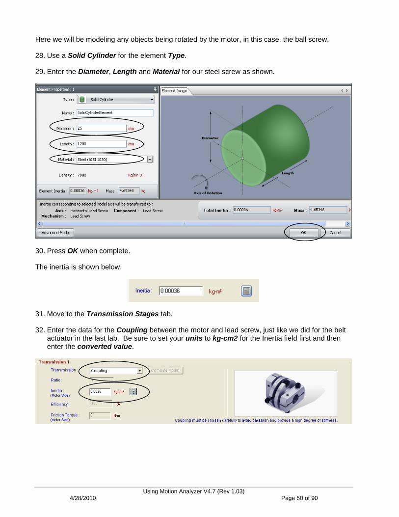
Here we will be modeling any objects being rotated by the motor, in this case, the ball screw.
28. Use a Solid Cylinder for the element Type.
29. Enter the Diameter, Length and Material for our steel screw as shown.
30. Press OK when complete.
The inertia is shown below.
31. Move to the Transmission Stages tab.
32. Enter the data for the Coupling between the motor and lead screw, just like we did for the belt actuator in the last lab. Be sure to set your units to kg-cm2 for the Inertia field first and then enter the converted value.
Using Motion Analyzer V4.7 (Rev 1.03) 4/28/2010 Page 50 of 90

Select a Motor and Drive
We have entered all of the known information and it is time to select the motor and drive. When using lead screw actuators, you are not typically required to use a gearbox.
33. Move to the Selection tab.
34. We will once again choose to Show the solutions within the Max Inertia Ratio and allow the software to automatically search for our motor and drive combination. Press Search when ready.
35. Sort the list by M+D Cost again.
You can see that the first two solutions are flagged as a Solution State 2, meaning “Caution.”
Using Motion Analyzer V4.7 (Rev 1.03) 4/28/2010 Page 51 of 90

36. Use the scroll bars to move over far enough to see that Inertia Ratio is causing this rating. It has exceeded our 80% safety margin.
37. Double-click on the third solution in the list, the MPL-B420P motor with the 2094-BMP5-S-250 drive.
The following note appears:
Important: The smaller 2094-BMP5-S drive will do the job, but not without some modification.
Please refer to Appendix A of this lab for the steps required to easily configure this drive for our enhanced usage.
38. Click OK to continue.
The bar graphs are all green and the Torque-Speed curve shows continuous and peak data points within the correct regions.
Using Motion Analyzer V4.7 (Rev 1.03) 4/28/2010 Page 52 of 90

The required speed and torque are actually quite low for this motor. Why didn’t the software choose a smaller motor? You can easily review the results of other motors (or drives) using the handy Previous/Next buttons in the bar graph area.
39. Use the Previous (<) button 2 times to view the performance of smaller motors.
It looks like Inertia is the reason the larger motor was chosen.
40. Use the Next (>) button to return to the MPL-B420P motor selection.
Using Motion Analyzer V4.7 (Rev 1.03) 4/28/2010 Page 53 of 90
Using the Ratio/Design Analysis Tool
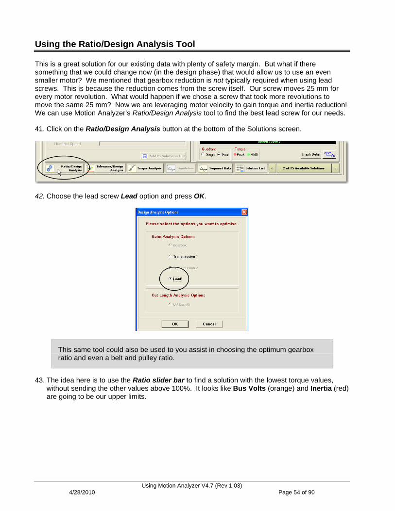
This is a great solution for our existing data with plenty of safety margin. But what if there something that we could change now (in the design phase) that would allow us to use an even smaller motor? We mentioned that gearbox reduction is not typically required when using lead screws. This is because the reduction comes from the screw itself. Our screw moves 25 mm for every motor revolution. What would happen if we chose a screw that took more revolutions to move the same 25 mm? Now we are leveraging motor velocity to gain torque and inertia reduction! We can use Motion Analyzer’s Ratio/Design Analysis tool to find the best lead screw for our needs.
41. Click on the Ratio/Design Analysis button at the bottom of the Solutions screen.
42. Choose the lead screw Lead option and press OK.
This same tool could also be used to you assist in choosing the optimum gearbox ratio and even a belt and pulley ratio.
43. The idea here is to use the Ratio slider bar to find a solution with the lowest torque values, without sending the other values above 100%. It looks like Bus Volts (orange) and Inertia (red) are going to be our upper limits.
Using Motion Analyzer V4.7 (Rev 1.03) 4/28/2010 Page 54 of 90
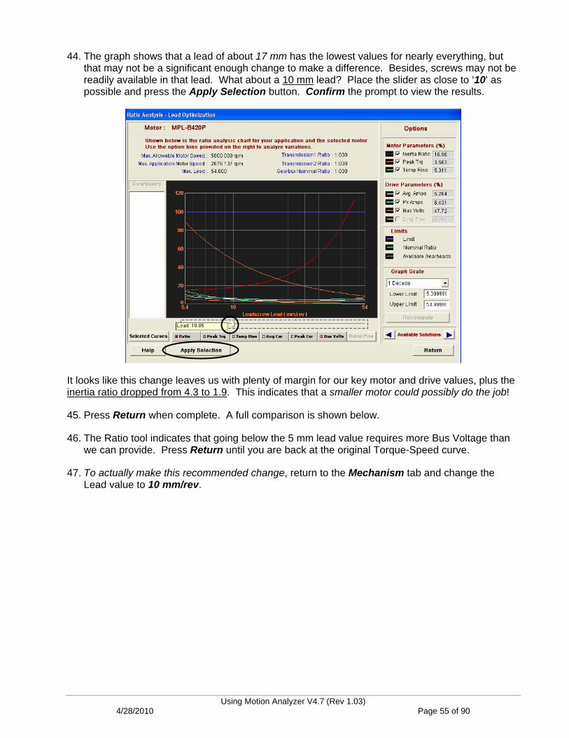
44. The graph shows that a lead of about 17 mm has the lowest values for nearly everything, but that may not be a significant enough change to make a difference. Besides, screws may not be readily available in that lead. What about a 10 mm lead? Place the slider as close to ‘10’ as possible and press the Apply Selection button. Confirm the prompt to view the results.
It looks like this change leaves us with plenty of margin for our key motor and drive values, plus the inertia ratio dropped from 4.3 to 1.9. This indicates that a smaller motor could possibly do the job!
45. Press Return when complete. A full comparison is shown below.
46. The Ratio tool indicates that going below the 5 mm lead value requires more Bus Voltage than we can provide. Press Return until you are back at the original Torque-Speed curve.
47. To actually make this recommended change, return to the Mechanism tab and change the Lead value to 10 mm/rev.
Using Motion Analyzer V4.7 (Rev 1.03) 4/28/2010 Page 55 of 90
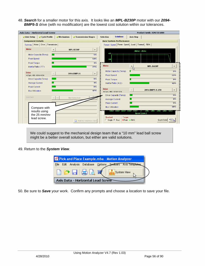
48. Search for a smaller motor for this axis. It looks like an MPL-B230P motor with our 2094-BMP5-S drive (with no modification) are the lowest cost solution within our tolerances.
Compare with results using the 25 mm/rev lead screw.
We could suggest to the mechanical design team that a “10 mm” lead ball screw might be a better overall solution, but either are valid solutions.
49. Return to the System View.
50. Be sure to Save your work. Confirm any prompts and choose a location to save your file.
Using Motion Analyzer V4.7 (Rev 1.03) 4/28/2010 Page 56 of 90

Lab 3: Sizing a Vertical Lead Screw (10 minutes)
About This Lab
We’ve completed sizing a horizontal lead screw, so we understand what is involved with this type of actuator. What happens when we use a lead screw in a vertical application? What are the effects of gravity on the motor and drive? What additional considerations are we responsible for investigating? In this lab, you will:
Reuse axis data from an existing axis
Edit the Move Profile Data in the Advanced Profile Editor
Select a motor and drive for your vertical lead screw axis
Analyze the system using the Shunt Analysis tool
Follow the steps below to complete Lab Section 3.
Reusing Existing Axis Data
If you’ve already created an axis of motion similar to your current axis in Motion Analyzer, you can easily copy and paste the data as a quick starting point. In this section of the lab, you will use the axis data from the previous lab (the horizontal lead screw) as the starting point for sizing the vertical lead screw axis.
Vertical Lead Screw Actuator.
Using Motion Analyzer V4.7 (Rev 1.03) 4/28/2010 Page 57 of 90
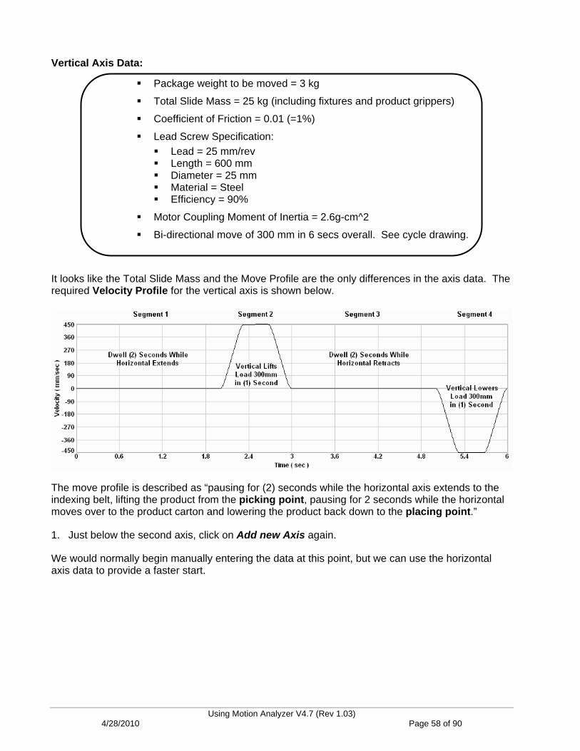
Vertical Axis Data:
Package weight to be moved = 3 kg
Total Slide Mass = 25 kg (including fixtures and product grippers)
Coefficient of Friction = 0.01 (=1%)
Lead Screw Specification: Lead = 25 mm/rev Length = 600 mm Diameter = 25 mm Material = Steel Efficiency = 90%
Motor Coupling Moment of Inertia = 2.6g-cm^2
Bi-directional move of 300 mm in 6 secs overall. See cycle drawing.
It looks like the Total Slide Mass and the Move Profile are the only differences in the axis data. The required Velocity Profile for the vertical axis is shown below.
The move profile is described as “pausing for (2) seconds while the horizontal axis extends to the indexing belt, lifting the product from the picking point, pausing for 2 seconds while the horizontal moves over to the product carton and lowering the product back down to the placing point.”
1. Just below the second axis, click on Add new Axis again.
We would normally begin manually entering the data at this point, but we can use the horizontal axis data to provide a faster start.
Using Motion Analyzer V4.7 (Rev 1.03) 4/28/2010 Page 58 of 90

2. Right-click on the Horizontal Lead Screw axis and select Copy Axis.
3. Next, right-click on Axis No.: 3 and select Paste Axis. Confirm by answering Yes to the prompt.
The information is brought in.
4. Double-click on Axis No.: 3 to begin editing the data for the vertical axis.
5. Begin on the Axis Setup tab.
All of the data is pre-populated here, since we copied it from axis 2.
6. Change the Axis Name to ‘Vertical Lead Screw’.
Using Motion Analyzer V4.7 (Rev 1.03) 4/28/2010 Page 59 of 90
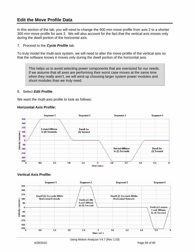
Edit the Move Profile Data
In this section of the lab, you will need to change the 600 mm move profile from axis 2 to a shorter 300 mm move profile for axis 3. We will also account for the fact that the vertical axis moves only during the dwell portion of the horizontal axis.
7. Proceed to the Cycle Profile tab.
To truly model the multi-axis system, we will need to alter the move profile of the vertical axis so that the software knows it moves only during the dwell portion of the horizontal axis.
This helps us to avoid selecting power components that are oversized for our needs. If we assume that all axes are performing their worst case moves at the same time when they really aren’t, we will wind up choosing larger system power modules and shunt modules than we truly need.
8. Select Edit Profile.
We want the multi-axis profile to look as follows:
Horizontal Axis Profile:
Vertical Axis Profile:
Using Motion Analyzer V4.7 (Rev 1.03)
4/28/2010 Page 60 of 90

Right away, we need to insert a dwell move in front of the existing trapezoidal move segment.
9. Click on Insert > Cruise / Dwell from the main menu.
10. Fill out the Segment Name, Velocity and Time settings as shown below.
11. Click on the Next Segment navigation arrow to move Segment 2.
Using Motion Analyzer V4.7 (Rev 1.03) 4/28/2010 Page 61 of 90

12. Enter the correct Move Distance and Move Time for our upward vertical profile.
Note that the Segment Load already includes our 3 kg Payload Mass from the horizontal axis data.
Once again, the Profile Editor is greatly improved in version 4.6 of the software.
13. Click on the Next Segment navigation arrow to move Segment 3.
14. Change the Dwell Time to ‘2’ seconds while the horizontal move completes the retraction move.
15. Click on the Next Segment navigation arrow to move Segment 4.
Using Motion Analyzer V4.7 (Rev 1.03) 4/28/2010 Page 62 of 90
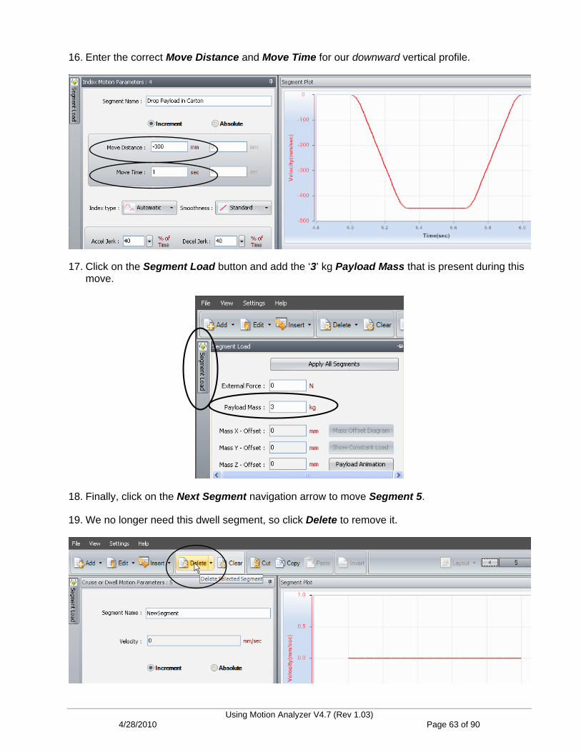
16. Enter the correct Move Distance and Move Time for our downward vertical profile.
17. Click on the Segment Load button and add the ‘3’ kg Payload Mass that is present during this move.
18. Finally, click on the Next Segment navigation arrow to move Segment 5.
19. We no longer need this dwell segment, so click Delete to remove it.
Using Motion Analyzer V4.7 (Rev 1.03) 4/28/2010 Page 63 of 90
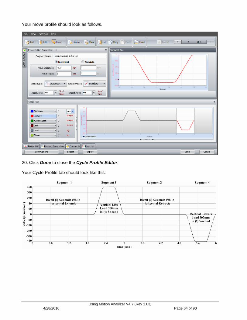
Your move profile should look as follows.
20. Click Done to close the Cycle Profile Editor.
Your Cycle Profile tab should look like this:
Using Motion Analyzer V4.7 (Rev 1.03) 4/28/2010 Page 64 of 90

Enter the Mechanical Data
21. Move to the Mechanism tab.
22. Most importantly, change the Inclination value to 90 degrees, to reflect our vertical axis. Press OK when the brake message appears.
NOTE: If power is ever removed from this vertical axis, the motor would not have the ability to hold (or stop) the load from falling. Therefore, we need to select an option that will do so. Since this is a factory only option, so we must be careful to remember to choose this motor option before we place an order.
23. If it isn’t already, set the Lead value to ‘25’ mm/rev from the application data. We will be much less affected by inertia on this smaller axis.
24. Click on the Inertia Calculator button as before.
Using Motion Analyzer V4.7 (Rev 1.03) 4/28/2010 Page 65 of 90

25. Change the Length value to the ‘600’ mm specified for this axis. Press OK when complete.
26. Change the Slide Mass to ‘25’ kg.
Your vertical lead screw data should look as follows:
The coupling is the same as from the horizontal axis, so we can skip the Transmission Stages tab.
Using Motion Analyzer V4.7 (Rev 1.03) 4/28/2010 Page 66 of 90

Select the Motor and Drive
27. Move to the Selection tab.
28. All of our preferences came over from the previous axis, so press the Search button to begin looking for a valid solution. Answer OK to the prompt about the motor brake again.
29. When the list appears, be sure that it is sorted by M+D Cost again and open the first green solution in the list.
30. Press OK to the reminder about the 250% settings required to use this drive.
This solution looks great and the motor and drive are some of the smallest that we offer. We are satisfied.
Using Motion Analyzer V4.7 (Rev 1.03) 4/28/2010 Page 67 of 90

NOTE: If you are concerned about using the lower power drive and having to manually set the Peak Current limits to 250%, simply press the ‘>’ arrow to view the axis’ performance using next larger rated drive.
The 2094-BM01-S drive does not require the custom settings, doesn’t take up any additional Kinetix power rail space and costs only about 15% more than the lower power drive.
31. Return to the System View as before.
32. Save your work.
Using Motion Analyzer V4.7 (Rev 1.03) 4/28/2010 Page 68 of 90

Analyze the System Shunt Requirements
You may have noticed the prompt that keeps appearing when you save your work. It mentions a system shunt. There are also some clues in the System View that alert us to the fact that we are not done yet.
Kinetix 2000 and 6000 drives are multi-axis drives and include (1) integrated axis module where the AC supply voltage is provided and up to (7) additional axis modules. The integrated axis modules contain a converter that creates an internal DC bus voltage on the backplane which powers the additional axis modules. The integrated axis module must be sized large enough to provide the required DC power to the axis modules.
Fig. 2 The left-most drive is the Integrated Axis Module and the others are expansion Axis Modules
Additionally, most servo drives contain a shunt resistor that helps to prevent the internal power bus from an overload. This is typically a concern when stopping the axis; especially when stopping a vertical axis from falling because gravity is working against you. Kinetix 2000 and 6000 drives can share their shunt capacity across the backplane, so if one drive requires additional stopping power and another drive has extra capacity, they work together. This can save on shunt costs and space requirements.
Motion Analyzer contains tools to assist you in determining the needs of your system.
Using Motion Analyzer V4.7 (Rev 1.03) 4/28/2010 Page 69 of 90

33. To select the proper integrated axis module and determine if your system requires additional shunting components, click on Power Supply / Accessories at the top of the screen.
As mentioned in the lab, the phase relationship between the various axis profiles in a common DC bus system affects the peak bus current requirement. For example, if all axes accelerate simultaneously, the bus current demand will be much greater than if each accelerates in turn. Drop-down boxes allow the user to set the axes for random or synchronized operation if you know this relationship.
The “safe” setting for system sizing is all set to “Random.” In this case, the worst case current demand for each axis is automatically lined up by adjusting the phase relationship of the axis profiles.
34. Since we took the time to enter our move profiles in real time, change the settings for Axis 2 and Axis 3 to Sync with Axis 1 for our system.
35. Press the Search IAM & Shunt button to automatically size and select your required components.
Using Motion Analyzer V4.7 (Rev 1.03) 4/28/2010 Page 70 of 90

36. Unless you know that Axis 1 is the largest or you are working with an existing system, select Arrange axes in order of decreasing power and press Perform Search.
The software is not requiring any additional shunting components. The internal shunts are sufficient in this application.
The software has changed the order of axes 2 and 3.
No additional shunting is required.
37. If you select the Graph tab, you can see that the Vertical axis does require the drive to absorb some regenerative bus current.
Using Motion Analyzer V4.7 (Rev 1.03) 4/28/2010 Page 71 of 90

NOTE: If your system requires external shunting, be sure to keep the continuous usage percentage below 20%. These types of chopper/resistor sets are typically rated for a 20% duty cycle. If you are an inverter drive user, you already know this.
If used, keep these ratings below 20%.
38. Return to the System View as before.
39. Save your work.
Your system is now complete! You can see the new order of the axes, as well as any motor, drive and gearbox part numbers. What about cables and accessories? There must be an easy tool for finding these, right?
Continue on with the Extra Task if you would like to use Motion Selector to create a complete bill of material for your motion system.
Using Motion Analyzer V4.7 (Rev 1.03) 4/28/2010 Page 72 of 90

Extra Task: Using Motion Selector (20 Minutes)
About This Lab
In the Extra Task, you can use the Motion Selector tool to create a complete bill of material for your motion system. Motion Selector does not include the controller items, such as your CompactLogix L43 controller, but it does include all motion-related components. This can include servo motors, drives and cables, as well as the motion module for your CompactLogix system and the SERCOS fiber cables to connect them all together. In this lab, you will:
Open Motion Selector and start with your Motion Analyzer file from labs 1-3 above
Use Motion Selector’s wizard tools to choose your axis components
Choose the motion accessories that complete your bill of material
Follow the steps below to complete the Extra Task.
Open Motion Selector
Motion Selector is installed when you install Motion Analyzer, but runs separately. There should be desktop icons for each tool, or you can find them in the Start > Programs > Rockwell Automation tree.
1. Open Motion Selector by double-clicking on the desktop shortcut.
2. Click on the Proceed button from opening screen.
Your choices are defined as follows:
Using Motion Analyzer V4.7 (Rev 1.03) 4/28/2010 Page 73 of 90

Create a Quick Quote – After selecting the drive platform, you are given a list of all motors, cables and accessories for that platform. You simply enter a quantity for the items that you need and can then create a bill of material of them when you are done. This selection requires that you know the part numbers of the items that you need.
Create a new Configuration – This selection allows you to select a drive platform and walks you through the (10) steps necessary to select a drive, motor, cables and all required accessories for each axis in your system. Although you do have to know your drive and motor part number, you can start with the ones already selected in Motion Analyzer simply by pointing to the completed system file. Selecting the rest of the components using this method is much more wizard driven.
Open existing Configuration – This selection allows you to continue working with a Motion Selector project that you previously saved to a file.
3. We will start with our existing Motion Analyzer file by selecting the second option. Give it the name ‘My Configuration’ and press continue.
4. Select the Start with an existing Motion Analyzer application radio button and press Browse to locate your existing file.
Using Motion Analyzer V4.7 (Rev 1.03) 4/28/2010 Page 74 of 90

5. Browse to the location of your Motion Analyzer file from above, select it and press Open.
6. On the Create New Configuration window, press continue.
Using Motion Analyzer V4.7 (Rev 1.03) 4/28/2010 Page 75 of 90

Select Motion Items for the Belt Indexer Axis
The selection of the motor and drive has already been completed for you, based on your selections from the Motion Analyzer file.
Axis 1 is our belt indexing axis and we can see Steps 1-4, have been selected for us.
7. Scroll down under Step 3: Motor/Actuator to view the motor that we selected for the Belt Indexing axis.
Similarly, the drive has been selected.
Use these drop-downs to specify options and motor preferences.
8. For Step 5, you’ll need to check the box to include a Motor Power Cable and then use the drop-down menu to select a Cable Length of 3m (10ft).
Using Motion Analyzer V4.7 (Rev 1.03) 4/28/2010 Page 76 of 90

9. Step 6 lets you choose either a pre-made cable or one with flying leads, but this also requires a connector. The note tells us that the connector is available in the Accessories section. Check the box for the Universal (flying lead) cable and select 3m (10ft) as above.
We don’t need a brake cable for our belt indexing axis, so skip Step 7.
Resistive Brake Modules are used to dynamically stop a moving axis in the event of a drive loosing power. Our safety auditor says that this system doesn’t require this option, so we will skip Steps 8 and 9.
Skip Step 10, since Kinetix drives already include these particular connector sets as shipped. We will choose additional connectors (for our control I/O and feedback) in the Accessories section.
10. Press continue to move on to the next axis.
Using Motion Analyzer V4.7 (Rev 1.03) 4/28/2010 Page 77 of 90
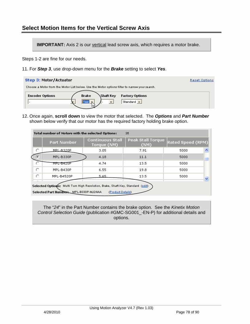
Select Motion Items for the Vertical Screw Axis
IMPORTANT: Axis 2 is our vertical lead screw axis, which requires a motor brake.
Steps 1-2 are fine for our needs.
11. For Step 3, use drop-down menu for the Brake setting to select Yes.
12. Once again, scroll down to view the motor that selected. The Options and Part Number shown below verify that our motor has the required factory holding brake option.
The “24” in the Part Number contains the brake option. See the Kinetix Motion Control Selection Guide (publication #GMC-SG001_-EN-P) for additional details and
options.
Using Motion Analyzer V4.7 (Rev 1.03) 4/28/2010 Page 78 of 90
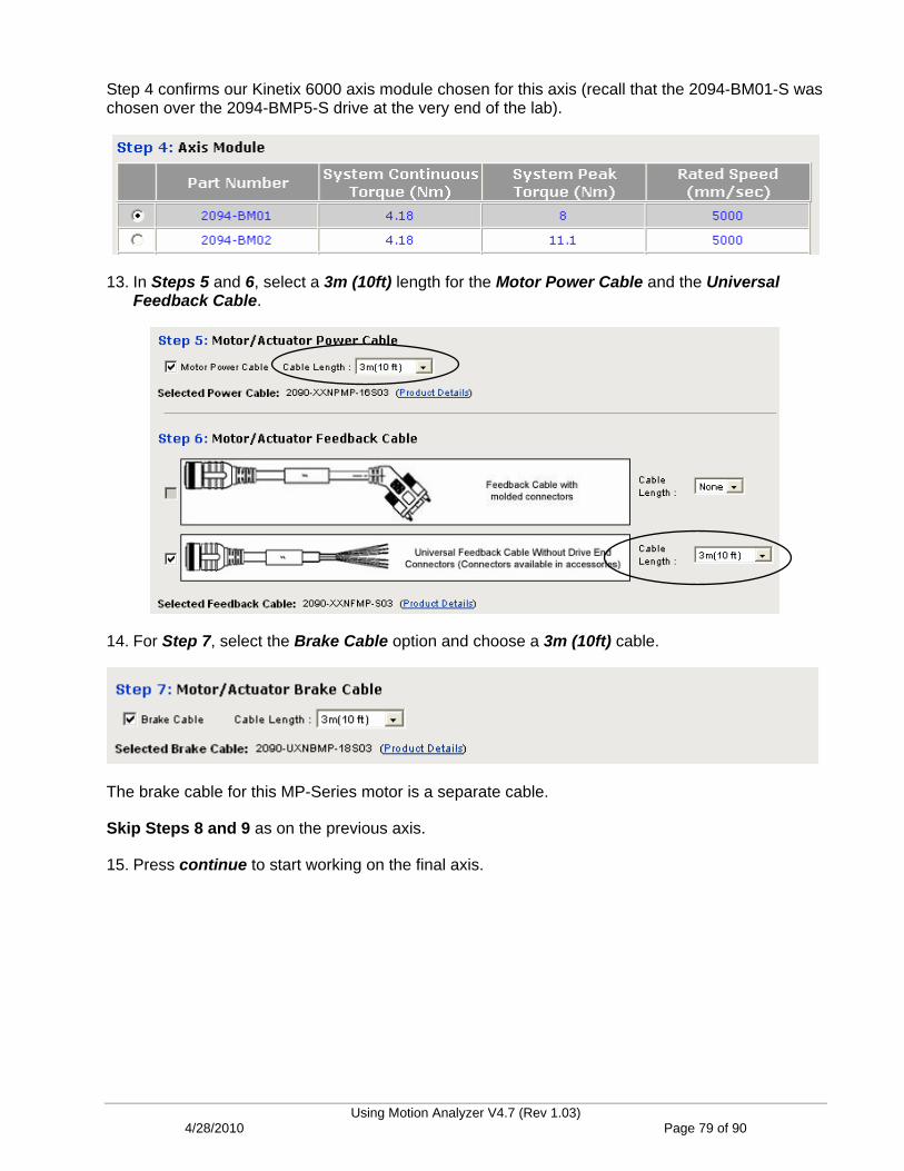
Step 4 confirms our Kinetix 6000 axis module chosen for this axis (recall that the 2094-BM01-S was chosen over the 2094-BMP5-S drive at the very end of the lab).
13. In Steps 5 and 6, select a 3m (10ft) length for the Motor Power Cable and the Universal Feedback Cable.
14. For Step 7, select the Brake Cable option and choose a 3m (10ft) cable.
The brake cable for this MP-Series motor is a separate cable.
Skip Steps 8 and 9 as on the previous axis.
15. Press continue to start working on the final axis.
Using Motion Analyzer V4.7 (Rev 1.03) 4/28/2010 Page 79 of 90

Select Motion Items for the Horizontal Screw Axis
Skip steps 1-4 since the motor and drive have already been selected through our Motion Analyzer file.
16. In Steps 5 and 6, select the same 3m (10ft) cables as above.
Skips Steps 7-9, as above.
17. Press continue to choose the system components and accessories.
Using Motion Analyzer V4.7 (Rev 1.03) 4/28/2010 Page 80 of 90
Choose the System Components
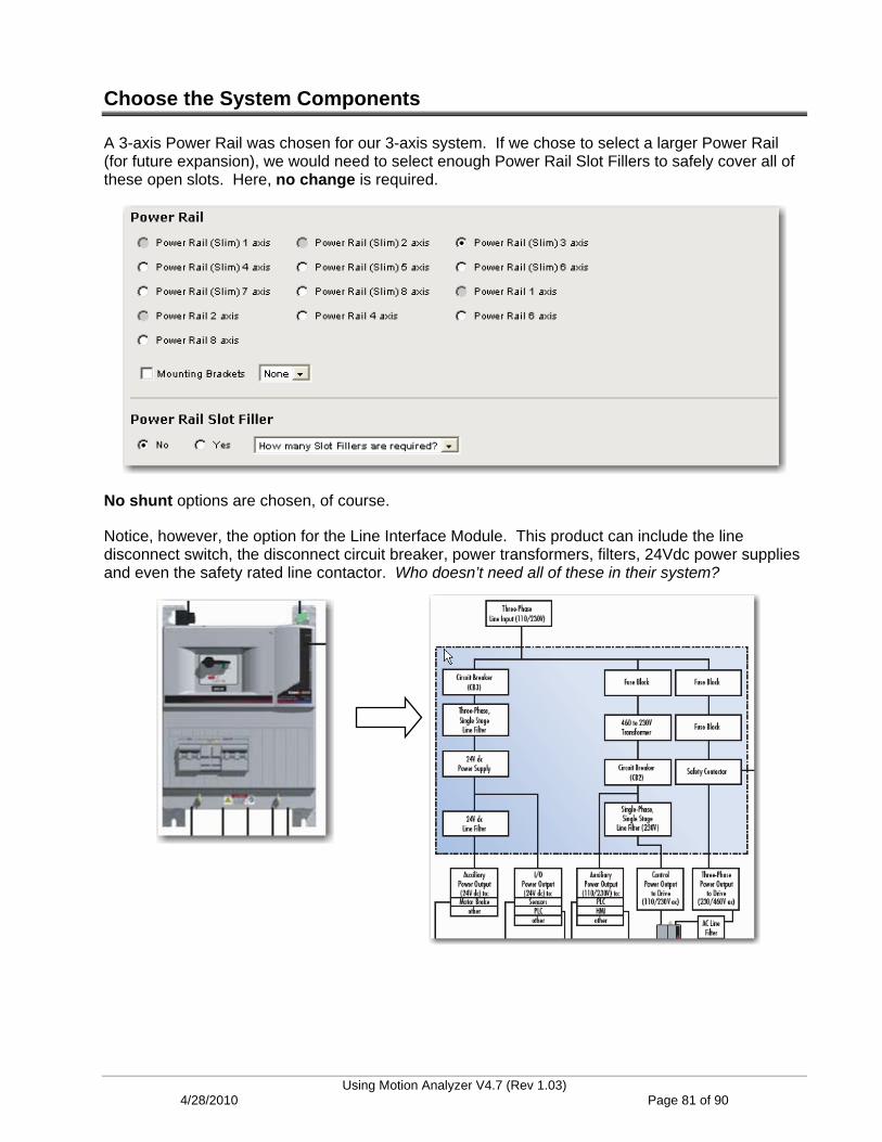
A 3-axis Power Rail was chosen for our 3-axis system. If we chose to select a larger Power Rail (for future expansion), we would need to select enough Power Rail Slot Fillers to safely cover all of these open slots. Here, no change is required.
No shunt options are chosen, of course.
Notice, however, the option for the Line Interface Module. This product can include the line disconnect switch, the disconnect circuit breaker, power transformers, filters, 24Vdc power supplies and even the safety rated line contactor. Who doesn’t need all of these in their system?
Using Motion Analyzer V4.7 (Rev 1.03) 4/28/2010 Page 81 of 90
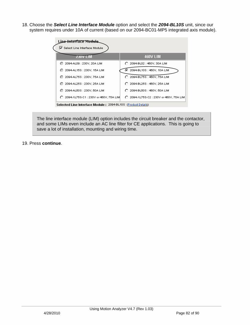
18. Choose the Select Line Interface Module option and select the 2094-BL10S unit, since our system requires under 10A of current (based on our 2094-BC01-MP5 integrated axis module).
The line interface module (LIM) option includes the circuit breaker and the contactor, and some LIMs even include an AC line filter for CE applications. This is going to save a lot of installation, mounting and wiring time.
19. Press continue.
Using Motion Analyzer V4.7 (Rev 1.03) 4/28/2010 Page 82 of 90

Choose the Motion Accessories
In this final section of the lab, you will add any of the required motion accessories or desired options to your bill of material. We’ll assume that we’ve used Integrated Architecture Builder to select our control system, so now we just need the motion components to make it complete.
20. On the Software & Accessories tab under Motion Control Module, select the 1768-M04SE SERCOS Module. This is the 4-axis SERCOS motion module for the CompactLogix L43 controller.
Since SERCOS is a ring-style topology, we will need to select fiber-optic cables to go from the motion module and back, as well as the ones that “jumper” from drive to drive.
21. In the SERCOS Cables section, we will choose Plastic cables only suited for use within an enclosure for our needs.
22. Select the Length of 3m (10ft) for the cables between the motion module and the drive. Be sure to enter a Quantity of ‘2‘ (since this is a ring topology) as well.
23. We will also need (2) of the 0.1m (5in) jumper cables between our (3) drives.
Using Motion Analyzer V4.7 (Rev 1.03) 4/28/2010 Page 83 of 90

24. Scroll down several sections to the Low Profile Connector Kits section.
This is where we will find the connector kits for the flying lead feedback cables, drive control I/O and even any auxiliary feedback devices, since each Kinetix drive supports an additional axis of auxiliary feedback right on board!
25. For our 3-axis system, choose (3) motor feedback connectors and (3) control I/O connectors, as shown below. The control I/O connector includes things like the drive enable signal, homing and over-travel limits and our brake relay for our vertical axis.
26. There are many other accessories that we could choose for our system, but let’s take a look at the bill of material. Scroll to the bottom of this page and press continue.
Using Motion Analyzer V4.7 (Rev 1.03) 4/28/2010 Page 84 of 90

View the Motion Bill of Material
27. The Summary tab shows the items we’ve selected for the general system and for each of the axes. You can view the axis details by expanding them, if you wish.
General system items.
The integrated axis, Axis 1.
28. Click on BOM View to continue.
Axis 3.
Axis 2 expanded.
Using Motion Analyzer V4.7 (Rev 1.03) 4/28/2010 Page 85 of 90

Your complete bill of material should display (you may have to expand the sections).
Motion Selector provides several convenient options for exporting and formatting your bill of material. You may wish to experiment with these.
29. Save your file if you wish and Exit Configuration when you are done.
Using Motion Analyzer V4.7 (Rev 1.03) 4/28/2010 Page 86 of 90

Appendix A: Drive Peak Torque Enhancements
About This Appendix
Launched in the fall of 2008, Kinetix 6000 Safe-Off servo drives (Series B and higher) can be configured to deliver up to 250% of rated continuous torque at limited duty cycles. In applications where acceleration torque is a concern, this enhancement may provide the following benefits:
Reduce Drive Size (up to 50% depending on application requirements)
Reduce System Cost (up to 45% depending on application requirements)
If the application has typically required a Kinetix 6000 drive that took (2) chassis slots, the peak enhancement might allow the application to use a smaller single slot drive, creating a space savings. Even if the application required a single slot drive in the past, the peak enhancement might allow the application to simply use a smaller drive. Here are the enhanced torque specifications for the single slot Kinetix 6000 drives:
Locating the Required Tools
If you have chosen a drive with a ‘-250’ in the catalog string, the drive must be configured for using 250% peak torque or it will not perform correctly. Motion Analyzer users are guided to the tools and steps required to implement the peak enhancement feature as shown below.
1. In Motion Analyzer software, click System View.
2. The yellow warning triangle indicates important information to the user. Click on the triangle for details.
Using Motion Analyzer V4.7 (Rev 1.03) 4/28/2010 Page 87 of 90
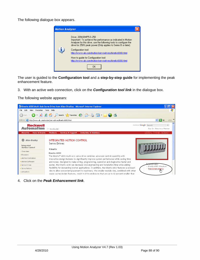
The following dialogue box appears.
The user is guided to the Configuration tool and a step-by-step guide for implementing the peak enhancement feature.
3. With an active web connection, click on the Configuration tool link in the dialogue box.
The following website appears:
4. Click on the Peak Enhancement link.
Using Motion Analyzer V4.7 (Rev 1.03) 4/28/2010 Page 88 of 90
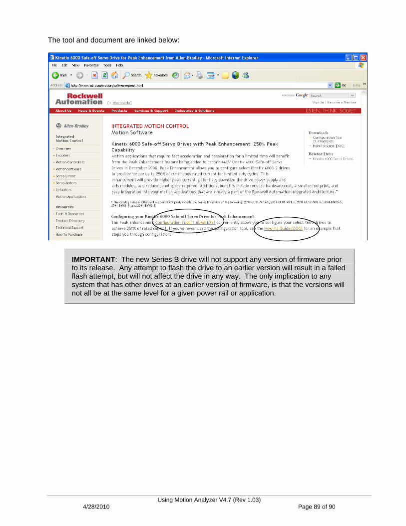
The tool and document are linked below:
IMPORTANT: The new Series B drive will not support any version of firmware prior to its release. Any attempt to flash the drive to an earlier version will result in a failed flash attempt, but will not affect the drive in any way. The only implication to any system that has other drives at an earlier version of firmware, is that the versions will not all be at the same level for a given power rail or application.
Using Motion Analyzer V4.7 (Rev 1.03) 4/28/2010 Page 89 of 90

Lab Summary
Motion Analyzer software is an excellent tool for sizing and selecting servo motor and drive components, as well as a great way to optimize machine components. SolidWorks users can save time identifying solutions by importing their existing machine models into Motion Analyzer.
Machine designers will find additional value in Motion Analyzer’s ability to identify optimum ratios for mechanical components, providing maximum system performance at the lowest possible cost.
You can download a copy of Motion Analyzer software at no charge by visiting www.ab.com/motion and clicking on Motion Software > Motion Analyzer from the side menus. Use the Current Updater feature to keep your software up to date.
If you require a tool that can create a complete Integrated Architecture bill of material, Motion Analyzer works with Integrated Architecture Builder software to produce system configurations that include controllers, networks and now motion components.
This concludes the Motion Analyzer lab.
Using Motion Analyzer V4.7 (Rev 1.03) 4/28/2010 Page 90 of 90