Embed Size (px)
Citation preview
B. Sivaraman, T. Burks, and J. Schueller. “Using Modern Robot Synthesis and Analysis Tools for the Design of Agricultural Manipulators”. Agricultural Engineering International: the CIGR Ejournal. Invited Overview Paper No. 2. Vol. VIII. January, 2006.
1
Using Modern Robot Synthesis and Analysis Tools for the Design of Agricultural Manipulators
B. Sivaraman1,2, T. F. Burks1, J. K. Schueller3 1 University of Florida, Dept. of Agr. and Bio. Engineering
2 P.O. Box 110570, Gainesville, FL 32611-0570, USA 3 University of Florida, Dept. of Mech. and Aero. Engineering
ABSTRACT In automating agricultural tasks, the ability to reach, grasp, and/or pick biological objects can be realized through the use of robot manipulators. As a basis for this effort, the robotic arm’s performance capabilities (dexterity, repeatability, etc.) need to be assessed before an appropriate configuration is chosen. The availability of modern computing tools can simplify this process. The objective of this paper is to demonstrate the use of modern computer aided design and analysis tools to select an appropriate configuration for an agricultural robot manipulator and to evaluate two of these tools; Robotics Toolbox and Robotect. The tree fruit harvesting task is chosen as an example to develop the design process and to show the utility of these tools for a particular application. In two of the available tools, Robotics Toolbox for Matlab and Robotect, a general five degree of freedom (DOF) arm configuration is modeled and analyzed to demonstrate their use in the overall design process. The Robotics Toolbox, without additional enhancements, has limited capabilities and can serve as a good initial design tool while Robotect’s many features enable it to be used in the generation and analysis of mechanical properties such as load capacity, accuracy, repeatability and torque requirement, along with a better visualization of these various parameters.
Keywords: Agricultural robot; design; harvesting; kinematics; manipulator; modeling; robot; software
1. INTRODUCTION
As the domain of robotic automation is ever widened, tasks that require human sensory perception, intelligence and dexterity in an unstructured environment are increasingly being considered for robots. As most of the tasks involving manual labor require the use of arm(s) and hand(s), the design of a robotic arm for a particular task usually plays a crucial role in realizing the design objective. Long-standing interest in the application of robotic automation to labor intensive agricultural tasks such as fruit harvesting has led to the development of agricultural robot manipulators as documented by Parrish and Goksel (1977), D’Esnon (1985), D’Esnon et. al. (1987), Harrell et. al. (1988), Sarig (1993), Rabatel et. al. (1995), Kondo et. al. (1996), and Ceres et. al. (1998). The apparent lag in commercializing the prototypes, which resulted from
B. Sivaraman, T. Burks, and J. Schueller. “Using Modern Robot Synthesis and Analysis Tools for the Design of Agricultural Manipulators”. Agricultural Engineering International: the CIGR Ejournal. Invited Overview Paper No. 2. Vol. VIII. January, 2006.
2
past developments, is primarily due to the high cost to benefit ratio. The technical shortfalls from previous research efforts are cited here: 80% detection of citrus fruits is reported by Juste and Sevila (1991) of which, 61% was reported to have foliage and branches in the trajectory of the arm leading to picking failures. Kassay and Slaughter (1993) reported a detection rate of ~70% and a picking rate of ~42% for apples. Again the presence of leaf and branch occlusions in the fruit picking path reduced the detection rates and thus the picking efficiency. Selecting the right sensing technology and manipulator configuration will enhance the detection capability and the manipulator dexterity, which should improve the picking efficiency. In the past, robot arms for agriculture are simplified in terms of the arm mobility as well as their construction. This is evident as many of the past research efforts adapted the basic 3 DOF spherical configuration. This could be attributed to an intended reduction in development time and cost as well as the unavailability of suitable modeling and analysis tools. The use of state-of-the-art synthesis tools for more sophisticated robot manipulator development is demonstrated in this article.
2. ROBOTIC MANIPULATOR SYNTHESIS/ANALYSIS TOOLS
The most general product design specifications (PDS) for robot manipulator design are:
• Type and layout of the joints.
• Geometry of the links.
• Materials, weight and dimensions of the links.
• Joint transmissions, sensors and actuators.
• Verified dexterity, workspace, accuracy, and static and dynamic performance.
In addition to these general specifications, the designer for an agricultural manipulator should deal with the uncertainty of the workspace, calculate efficient cycle times, evaluate alternatives quickly with optimal confidence, and must work within the economic threshold for the particular application. Traditionally when the designer is faced with numerous choices for the type and layout of the joints in the initial design phase, selection is based on the knowledge of the task, the workspace and his/her own experience. The margin for error in this process is very low as this would incur additional cost and time to the project, at the least. An alternative to this approach is to employ software tools that aid the designer in the design process. The use of modern synthesis and analysis software tools can give the designer the flexibility and agility in exploring alternatives by building computer generated models, which increases his/her confidence in the design selection.
2.1 Manipulator modeling fundamentals Robot manipulator modeling consists of a geometrical definition along with a kinematical description of the linkages. The geometrical definition can be accomplished by creating representative three-dimensional (3D) computer aided graphic models whereas the kinematic entities describing the relations between links, velocities, accelerations and other characteristics of the manipulator can be obtained from robot kinematic theory based upon Denavit-Hartenberg (D-H) parameters (Craig, 2003). The structural design of the components of a robot manipulator
B. Sivaraman, T. Burks, and J. Schueller. “Using Modern Robot Synthesis and Analysis Tools for the Design of Agricultural Manipulators”. Agricultural Engineering International: the CIGR Ejournal. Invited Overview Paper No. 2. Vol. VIII. January, 2006.
3
uses the optimized geometric entities resulting from the previous stages. Though there are numerous software packages available for 3D modeling and motion simulation, there is not one all inclusive package that could output the exact physical (3D characteristics) and functional description (motion planning) of the robot. The simulation itself consists of the kinematic and dynamic parts depending upon whether or not the actuator forces and torques are considered when generating motion trajectories. Once the functional description of the manipulator is finalized, any of the widely available solid modeling tools could be used for the accurate description of the robot’s 3D geometry and an extensive structural analysis could be performed. A detailed discussion of structural modeling and analysis is not within the scope of this article.
2.2 Kinematic synthesis tools
The kinematic design of the robot defines its functional characteristics. From the general PDS and the specific requirements for an agricultural setting, a kinematic design tool is expected to possess the following:
• Define multiple joint-link pairs and describe transformations between the joint-link pairs.
• Perform forward and inverse kinematics. Forward kinematics is the problem of finding the unique location of the last link or the end-effector of the robot for the given set of joint values while inverse kinematics outputs the joint positions for a given end-effector position and orientation.
• Generate time-varying trajectories and evaluate arm dynamics for those trajectories.
• Create three-dimensional geometry from given input for graphical simulations.
• Have built-in basic performance measures to evaluate and verify design alternatives.
• Have numerical and graphical output capability.
Apart from these, additional qualities such as, ease of creating alternative configurations, ability to accept dynamic parameters, perform forward and inverse dynamics (for joint accelerations and torques), ability to extend performance studies throughout the workspace, etc., will be extremely useful. For example, due to the variability in the fruit picking environment, a good performance measure for the manipulator design can be to evaluate the dexterity of the manipulator along the workspace.
Packages available to model and simulate general mechanisms and robots are: Robotics Toolbox, a collection of functions written in MATLAB for serial link robot design, Robotect, a modeling and analysis tool for serial link robot design, RobotAssist, a robot modeling and control package, and Cimstation Robotics, a 3D simulation software for manufacturing automation. All the software packages are available for the Windows operating system and have basic capabilities such as, D-H parameter based robot creation, forward and inverse kinematics, and trajectory generation. They differ in the availability of performance measures, control diagnostics, user interface, etc. A comparative study of Robotics Toolbox and Robotect is presented in this article and can serve as a guideline for the reader in analyzing various features of the tools before choosing one that best suit his/her needs.
B. Sivaraman, T. Burks, and J. Schueller. “Using Modern Robot Synthesis and Analysis Tools for the Design of Agricultural Manipulators”. Agricultural Engineering International: the CIGR Ejournal. Invited Overview Paper No. 2. Vol. VIII. January, 2006.
4
3. MATLAB ROBOTICS TOOLBOX AND ROBOTECT: A COMPARISON STUDY
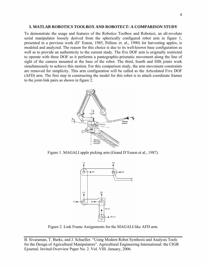
To demonstrate the usage and features of the Robotics Toolbox and Robotect, an all-revolute serial manipulator loosely derived from the spherically configured robot arm in figure 1, presented in a previous work (D’ Esnon, 1985, Pellenc et. al., 1990) for harvesting apples, is modeled and analyzed. The reason for this choice is due to its well-known base configuration as well as to provide an authenticity to the current study. The five DOF arm is originally restricted to operate with three DOF as it performs a pantographic-prismatic movement along the line of sight of the camera mounted at the base of the robot. The third, fourth and fifth joints work simultaneously to achieve this motion. For this comparison study, the arm movement constraints are removed for simplicity. This arm configuration will be called as the Articulated Five DOF (AFD) arm. The first step in constructing the model for this robot is to attach coordinate frames to the joint-link pairs as shown in figure 2.
Figure 1. MAGALI apple picking arm (Grand D’Esnon et al., 1987).
Figure 2. Link Frame Assignments for the MAGALI-like AFD arm.
B. Sivaraman, T. Burks, and J. Schueller. “Using Modern Robot Synthesis and Analysis Tools for the Design of Agricultural Manipulators”. Agricultural Engineering International: the CIGR Ejournal. Invited Overview Paper No. 2. Vol. VIII. January, 2006.
5
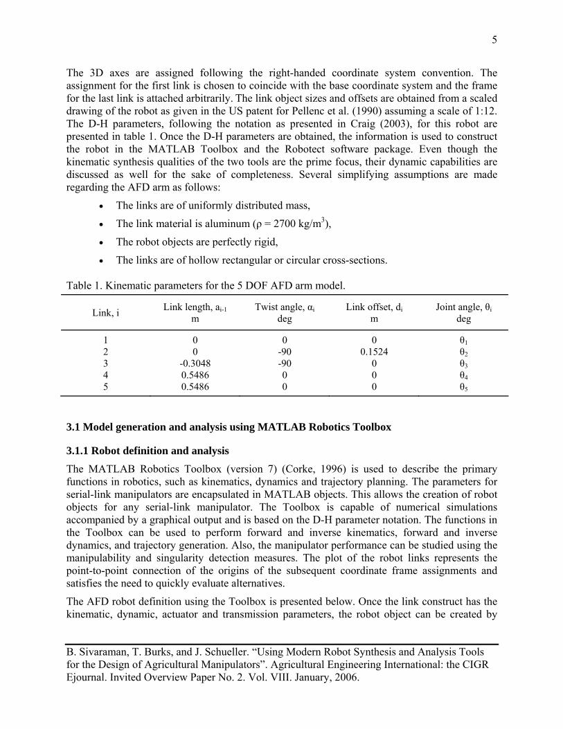
The 3D axes are assigned following the right-handed coordinate system convention. The assignment for the first link is chosen to coincide with the base coordinate system and the frame for the last link is attached arbitrarily. The link object sizes and offsets are obtained from a scaled drawing of the robot as given in the US patent for Pellenc et al. (1990) assuming a scale of 1:12. The D-H parameters, following the notation as presented in Craig (2003), for this robot are presented in table 1. Once the D-H parameters are obtained, the information is used to construct the robot in the MATLAB Toolbox and the Robotect software package. Even though the kinematic synthesis qualities of the two tools are the prime focus, their dynamic capabilities are discussed as well for the sake of completeness. Several simplifying assumptions are made regarding the AFD arm as follows:
• The links are of uniformly distributed mass,
• The link material is aluminum (ρ = 2700 kg/m3),
• The robot objects are perfectly rigid,
• The links are of hollow rectangular or circular cross-sections. Table 1. Kinematic parameters for the 5 DOF AFD arm model.
Link, i Link length, ai-1 m
Twist angle, αi deg
Link offset, di m
Joint angle, θi deg
1 2 3 4 5
0 0
-0.3048 0.5486 0.5486
0 -90 -90 0 0
0 0.1524
0 0 0
θ1 θ2 θ3 θ4 θ5
3.1 Model generation and analysis using MATLAB Robotics Toolbox
3.1.1 Robot definition and analysis
The MATLAB Robotics Toolbox (version 7) (Corke, 1996) is used to describe the primary functions in robotics, such as kinematics, dynamics and trajectory planning. The parameters for serial-link manipulators are encapsulated in MATLAB objects. This allows the creation of robot objects for any serial-link manipulator. The Toolbox is capable of numerical simulations accompanied by a graphical output and is based on the D-H parameter notation. The functions in the Toolbox can be used to perform forward and inverse kinematics, forward and inverse dynamics, and trajectory generation. Also, the manipulator performance can be studied using the manipulability and singularity detection measures. The plot of the robot links represents the point-to-point connection of the origins of the subsequent coordinate frame assignments and satisfies the need to quickly evaluate alternatives.
The AFD robot definition using the Toolbox is presented below. Once the link construct has the kinematic, dynamic, actuator and transmission parameters, the robot object can be created by
B. Sivaraman, T. Burks, and J. Schueller. “Using Modern Robot Synthesis and Analysis Tools for the Design of Agricultural Manipulators”. Agricultural Engineering International: the CIGR Ejournal. Invited Overview Paper No. 2. Vol. VIII. January, 2006.
6
concatenating the link objects. An example link object and robot construction in MATLAB with few sub-assignments for link 4 is shown below. l{4} = link([0 .5486 0 0 0],'modified'); %link kinematic definition
l{4}.m = rho * 0.0016; %link mass = density x volume
l{4}.r = [0.2743 0 0]; %link COG
l{4}.I = [.1199 .1222 .5427 0 0 0]; %inertia vector about link COG
l{4}.qlim = [0 deg2rad(165)]; %joint limits
AFD_mdh = robot(l, ‘AFD_mdh’); %AFD robot object definition
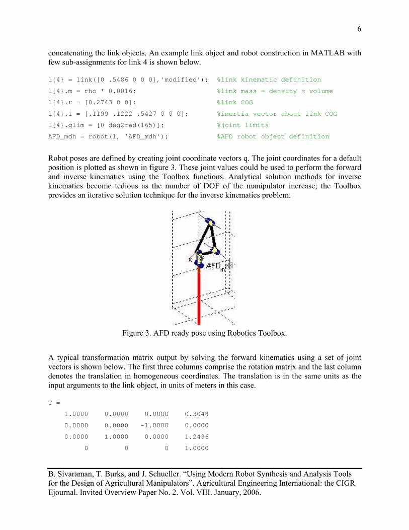
Robot poses are defined by creating joint coordinate vectors q. The joint coordinates for a default position is plotted as shown in figure 3. These joint values could be used to perform the forward and inverse kinematics using the Toolbox functions. Analytical solution methods for inverse kinematics become tedious as the number of DOF of the manipulator increase; the Toolbox provides an iterative solution technique for the inverse kinematics problem.
Figure 3. AFD ready pose using Robotics Toolbox.
A typical transformation matrix output by solving the forward kinematics using a set of joint vectors is shown below. The first three columns comprise the rotation matrix and the last column denotes the translation in homogeneous coordinates. The translation is in the same units as the input arguments to the link object, in units of meters in this case. T =
1.0000 0.0000 0.0000 0.3048
0.0000 0.0000 -1.0000 0.0000
0.0000 1.0000 0.0000 1.2496
0 0 0 1.0000
B. Sivaraman, T. Burks, and J. Schueller. “Using Modern Robot Synthesis and Analysis Tools for the Design of Agricultural Manipulators”. Agricultural Engineering International: the CIGR Ejournal. Invited Overview Paper No. 2. Vol. VIII. January, 2006.
7
Thus the matrix computation methods in MATLAB can be effectively used for kinematic and dynamic solutions and for motion generation algorithms.
3.1.2 Performance measures in the Toolbox
The manipulator Jacobian, a matrix quantity that maps the velocity between joint and Cartesian space is widely used in control algorithms. The well known equation of this relation is as follows:
•= qqJv )( (1)
where v = Cartesian velocity vector, J = manipulator Jacobian, and q = joint angle vector.
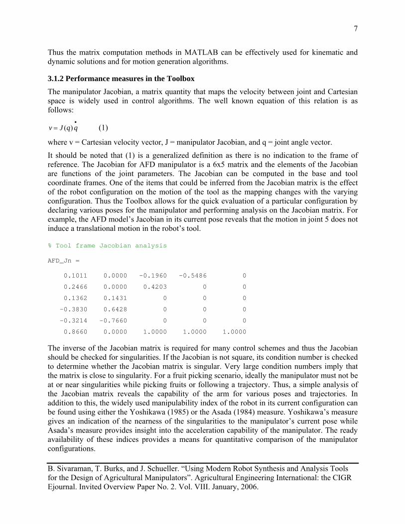
It should be noted that (1) is a generalized definition as there is no indication to the frame of reference. The Jacobian for AFD manipulator is a 6x5 matrix and the elements of the Jacobian are functions of the joint parameters. The Jacobian can be computed in the base and tool coordinate frames. One of the items that could be inferred from the Jacobian matrix is the effect of the robot configuration on the motion of the tool as the mapping changes with the varying configuration. Thus the Toolbox allows for the quick evaluation of a particular configuration by declaring various poses for the manipulator and performing analysis on the Jacobian matrix. For example, the AFD model’s Jacobian in its current pose reveals that the motion in joint 5 does not induce a translational motion in the robot’s tool. % Tool frame Jacobian analysis
AFD_Jn = 0.1011 0.0000 -0.1960 -0.5486 0
0.2466 0.0000 0.4203 0 0
0.1362 0.1431 0 0 0
-0.3830 0.6428 0 0 0
-0.3214 -0.7660 0 0 0
0.8660 0.0000 1.0000 1.0000 1.0000
The inverse of the Jacobian matrix is required for many control schemes and thus the Jacobian should be checked for singularities. If the Jacobian is not square, its condition number is checked to determine whether the Jacobian matrix is singular. Very large condition numbers imply that the matrix is close to singularity. For a fruit picking scenario, ideally the manipulator must not be at or near singularities while picking fruits or following a trajectory. Thus, a simple analysis of the Jacobian matrix reveals the capability of the arm for various poses and trajectories. In addition to this, the widely used manipulability index of the robot in its current configuration can be found using either the Yoshikawa (1985) or the Asada (1984) measure. Yoshikawa’s measure gives an indication of the nearness of the singularities to the manipulator’s current pose while Asada’s measure provides insight into the acceleration capability of the manipulator. The ready availability of these indices provides a means for quantitative comparison of the manipulator configurations.
B. Sivaraman, T. Burks, and J. Schueller. “Using Modern Robot Synthesis and Analysis Tools for the Design of Agricultural Manipulators”. Agricultural Engineering International: the CIGR Ejournal. Invited Overview Paper No. 2. Vol. VIII. January, 2006.
8
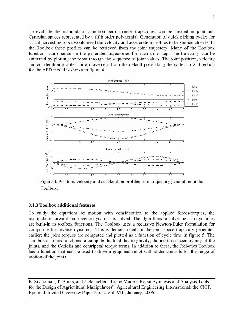
To evaluate the manipulator’s motion performance, trajectories can be created in joint and Cartesian spaces represented by a fifth order polynomial. Generation of quick picking cycles for a fruit harvesting robot would need the velocity and acceleration profiles to be studied closely. In the Toolbox these profiles can be retrieved from the joint trajectory. Many of the Toolbox functions can operate on the generated trajectories for each time step. The trajectory can be animated by plotting the robot through the sequence of joint values. The joint position, velocity and acceleration profiles for a movement from the default pose along the cartesian X-direction for the AFD model is shown in figure 4.
Figure 4. Position, velocity and acceleration profiles from trajectory generation in the
Toolbox.
3.1.3 Toolbox additional features
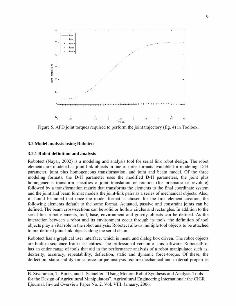
To study the equations of motion with consideration to the applied forces/torques, the manipulator forward and inverse dynamics is solved. The algorithms to solve the arm dynamics are built-in as toolbox functions. The Toolbox uses a recursive Newton-Euler formulation for computing the inverse dynamics. This is demonstrated for the joint space trajectory generated earlier; the joint torques are computed and plotted as a function of cycle time in figure 5. The Toolbox also has functions to compute the load due to gravity, the inertia as seen by any of the joints, and the Coriolis and centripetal torque terms. In addition to these, the Robotics Toolbox has a function that can be used to drive a graphical robot with slider controls for the range of motion of the joints.
B. Sivaraman, T. Burks, and J. Schueller. “Using Modern Robot Synthesis and Analysis Tools for the Design of Agricultural Manipulators”. Agricultural Engineering International: the CIGR Ejournal. Invited Overview Paper No. 2. Vol. VIII. January, 2006.
9
Figure 5. AFD joint torques required to perform the joint trajectory (fig. 4) in Toolbox.
3.2 Model analysis using Robotect
3.2.1 Robot definition and analysis
Robotect (Nayar, 2002) is a modeling and analysis tool for serial link robot design. The robot elements are modeled as joint-link objects in one of three formats available for modeling: D-H parameter, joint plus homogeneous transformation, and joint and beam model. Of the three modeling formats, the D-H parameter uses the modified D-H parameters, the joint plus homogeneous transform specifies a joint translation or rotation (for prismatic or revolute) followed by a transformation matrix that transforms the elements to the final coordinate system and the joint and beam format models the joint-link pairs as a series of mechanical objects. Also, it should be noted that once the model format is chosen for the first element creation, the following elements default to the same format. Actuated, passive and constraint joints can be defined. The beam cross-sections can be solid or hollow circles and rectangles. In addition to the serial link robot elements, tool, base, environment and gravity objects can be defined. As the interaction between a robot and its environment occur through its tools, the definition of tool objects play a vital role in the robot analysis. Robotect allows multiple tool objects to be attached to pre-defined joint-link objects along the serial chain.
Robotect has a graphical user interface, which is menu and dialog box driven. The robot objects are built in sequence from user entries. The professional version of this software, RobotectPro, has an entire range of tools that aid in the performance analysis of a robot manipulator such as, dexterity, accuracy, repeatability, deflection, static and dynamic force-torque. Of these, the deflection, static and dynamic force-torque analysis require mechanical and material properties
B. Sivaraman, T. Burks, and J. Schueller. “Using Modern Robot Synthesis and Analysis Tools for the Design of Agricultural Manipulators”. Agricultural Engineering International: the CIGR Ejournal. Invited Overview Paper No. 2. Vol. VIII. January, 2006.
10
that are input only in the joint and beam model format. The readily available forward and inverse kinematic and the inverse dynamic solvers are used for these purposes. The default inverse kinematics algorithm uses a nonlinear constrained optimization technique to arrive at the solution. However, there is a possibility to test other algorithms written in MATLAB or Excel using specified input and output format. Also, there is a trajectory generation feature for motion planning and analysis in either the joint space or the Cartesian space. The Cartesian trajectory generation option, if chosen, will check for available inverse kinematic solution using the default or user-specified algorithm.
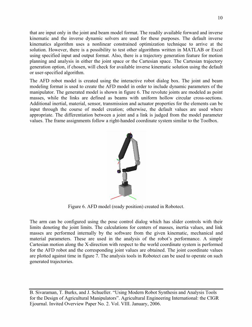
The AFD robot model is created using the interactive robot dialog box. The joint and beam modeling format is used to create the AFD model in order to include dynamic parameters of the manipulator. The generated model is shown in figure 6. The revolute joints are modeled as point masses, while the links are defined as beams with uniform hollow circular cross-sections. Additional inertial, material, sensor, transmission and actuator properties for the elements can be input through the course of model creation; otherwise, the default values are used where appropriate. The differentiation between a joint and a link is judged from the model parameter values. The frame assignments follow a right-handed coordinate system similar to the Toolbox.
Figure 6. AFD model (ready position) created in Robotect.
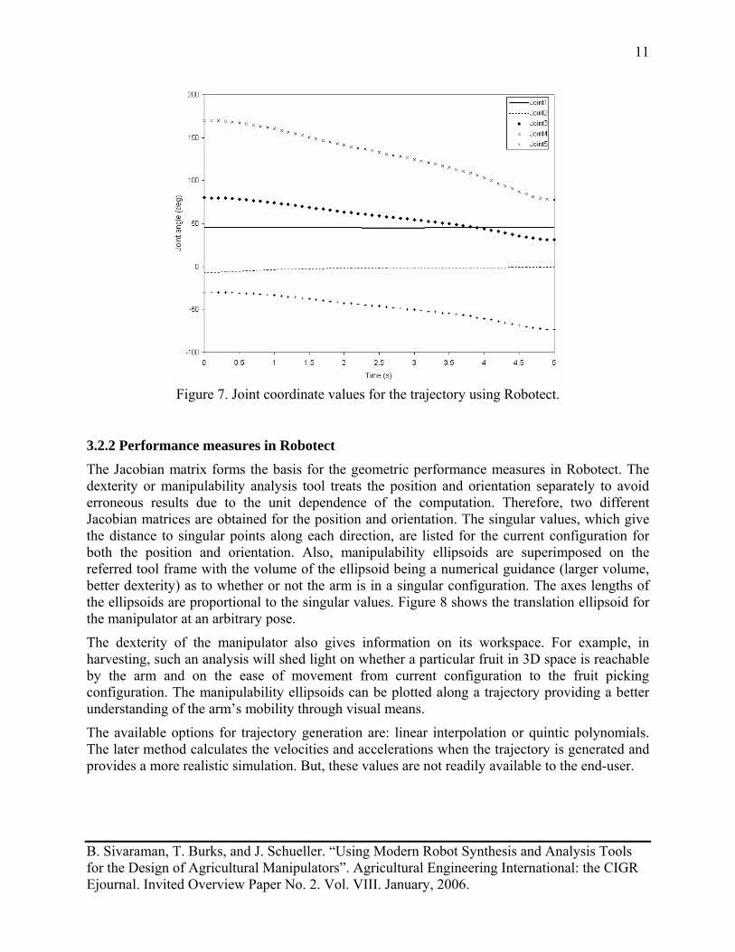
The arm can be configured using the pose control dialog which has slider controls with their limits denoting the joint limits. The calculations for centers of masses, inertia values, and link masses are performed internally by the software from the given kinematic, mechanical and material parameters. These are used in the analysis of the robot’s performance. A simple Cartesian motion along the X-direction with respect to the world coordinate system is performed for the AFD robot and the corresponding joint values are obtained. The joint coordinate values are plotted against time in figure 7. The analysis tools in Robotect can be used to operate on such generated trajectories.
B. Sivaraman, T. Burks, and J. Schueller. “Using Modern Robot Synthesis and Analysis Tools for the Design of Agricultural Manipulators”. Agricultural Engineering International: the CIGR Ejournal. Invited Overview Paper No. 2. Vol. VIII. January, 2006.
11
Figure 7. Joint coordinate values for the trajectory using Robotect.
3.2.2 Performance measures in Robotect
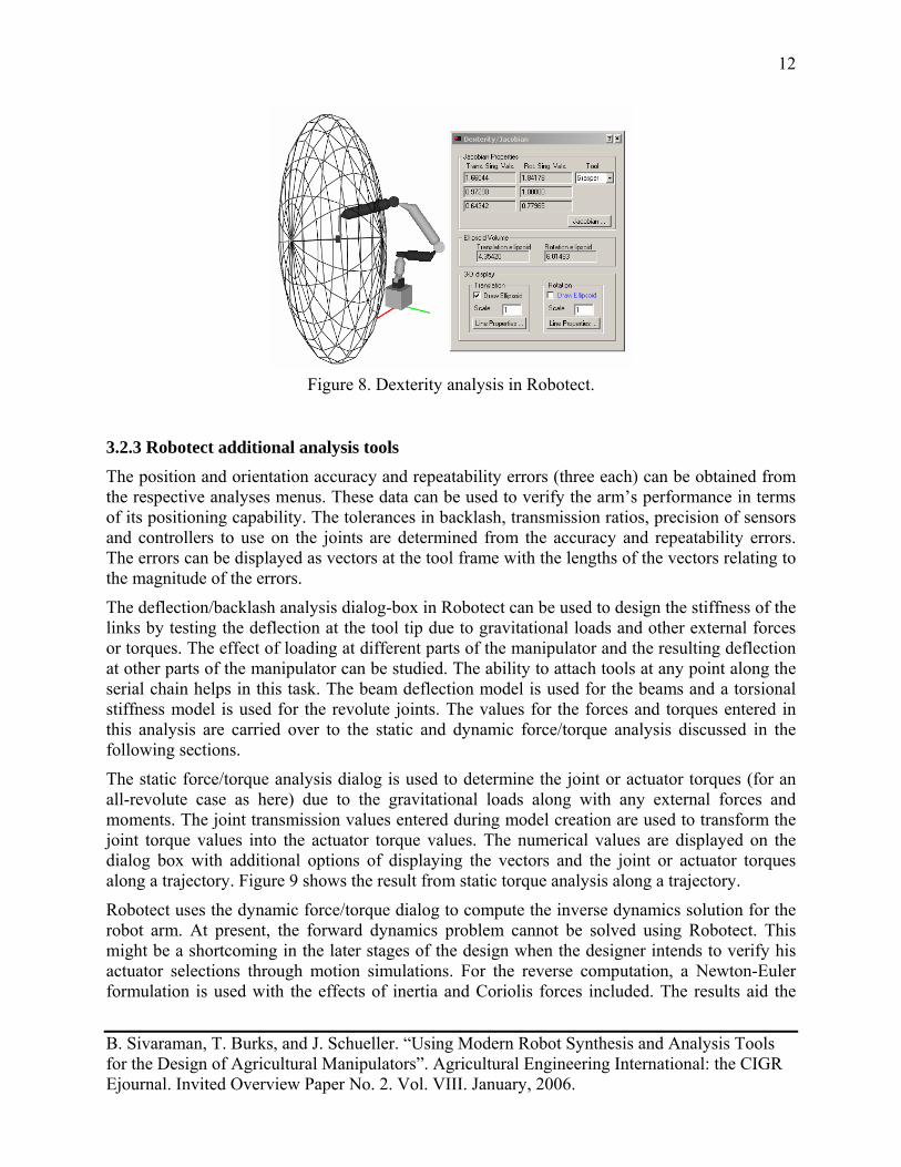
The Jacobian matrix forms the basis for the geometric performance measures in Robotect. The dexterity or manipulability analysis tool treats the position and orientation separately to avoid erroneous results due to the unit dependence of the computation. Therefore, two different Jacobian matrices are obtained for the position and orientation. The singular values, which give the distance to singular points along each direction, are listed for the current configuration for both the position and orientation. Also, manipulability ellipsoids are superimposed on the referred tool frame with the volume of the ellipsoid being a numerical guidance (larger volume, better dexterity) as to whether or not the arm is in a singular configuration. The axes lengths of the ellipsoids are proportional to the singular values. Figure 8 shows the translation ellipsoid for the manipulator at an arbitrary pose.
The dexterity of the manipulator also gives information on its workspace. For example, in harvesting, such an analysis will shed light on whether a particular fruit in 3D space is reachable by the arm and on the ease of movement from current configuration to the fruit picking configuration. The manipulability ellipsoids can be plotted along a trajectory providing a better understanding of the arm’s mobility through visual means.
The available options for trajectory generation are: linear interpolation or quintic polynomials. The later method calculates the velocities and accelerations when the trajectory is generated and provides a more realistic simulation. But, these values are not readily available to the end-user.
B. Sivaraman, T. Burks, and J. Schueller. “Using Modern Robot Synthesis and Analysis Tools for the Design of Agricultural Manipulators”. Agricultural Engineering International: the CIGR Ejournal. Invited Overview Paper No. 2. Vol. VIII. January, 2006.
12
Figure 8. Dexterity analysis in Robotect.
3.2.3 Robotect additional analysis tools
The position and orientation accuracy and repeatability errors (three each) can be obtained from the respective analyses menus. These data can be used to verify the arm’s performance in terms of its positioning capability. The tolerances in backlash, transmission ratios, precision of sensors and controllers to use on the joints are determined from the accuracy and repeatability errors. The errors can be displayed as vectors at the tool frame with the lengths of the vectors relating to the magnitude of the errors.
The deflection/backlash analysis dialog-box in Robotect can be used to design the stiffness of the links by testing the deflection at the tool tip due to gravitational loads and other external forces or torques. The effect of loading at different parts of the manipulator and the resulting deflection at other parts of the manipulator can be studied. The ability to attach tools at any point along the serial chain helps in this task. The beam deflection model is used for the beams and a torsional stiffness model is used for the revolute joints. The values for the forces and torques entered in this analysis are carried over to the static and dynamic force/torque analysis discussed in the following sections.
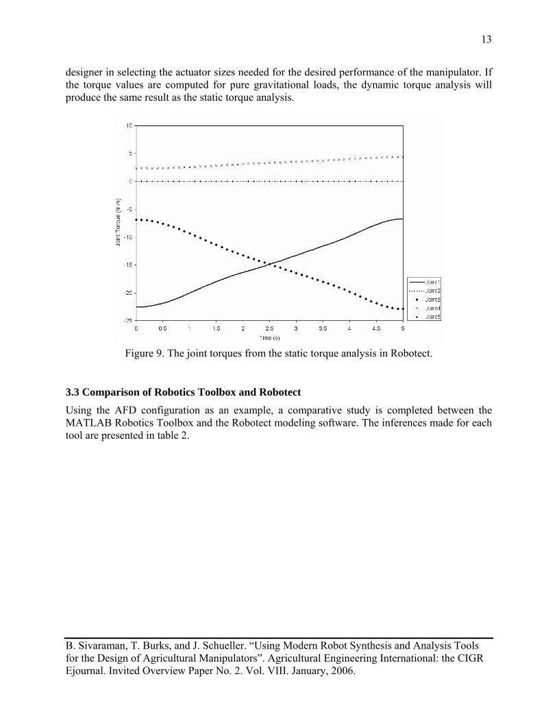
The static force/torque analysis dialog is used to determine the joint or actuator torques (for an all-revolute case as here) due to the gravitational loads along with any external forces and moments. The joint transmission values entered during model creation are used to transform the joint torque values into the actuator torque values. The numerical values are displayed on the dialog box with additional options of displaying the vectors and the joint or actuator torques along a trajectory. Figure 9 shows the result from static torque analysis along a trajectory.
Robotect uses the dynamic force/torque dialog to compute the inverse dynamics solution for the robot arm. At present, the forward dynamics problem cannot be solved using Robotect. This might be a shortcoming in the later stages of the design when the designer intends to verify his actuator selections through motion simulations. For the reverse computation, a Newton-Euler formulation is used with the effects of inertia and Coriolis forces included. The results aid the
B. Sivaraman, T. Burks, and J. Schueller. “Using Modern Robot Synthesis and Analysis Tools for the Design of Agricultural Manipulators”. Agricultural Engineering International: the CIGR Ejournal. Invited Overview Paper No. 2. Vol. VIII. January, 2006.
13
designer in selecting the actuator sizes needed for the desired performance of the manipulator. If the torque values are computed for pure gravitational loads, the dynamic torque analysis will produce the same result as the static torque analysis.
Figure 9. The joint torques from the static torque analysis in Robotect.
3.3 Comparison of Robotics Toolbox and Robotect
Using the AFD configuration as an example, a comparative study is completed between the MATLAB Robotics Toolbox and the Robotect modeling software. The inferences made for each tool are presented in table 2.
B. Sivaraman, T. Burks, and J. Schueller. “Using Modern Robot Synthesis and Analysis Tools for the Design of Agricultural Manipulators”. Agricultural Engineering International: the CIGR Ejournal. Invited Overview Paper No. 2. Vol. VIII. January, 2006.
14
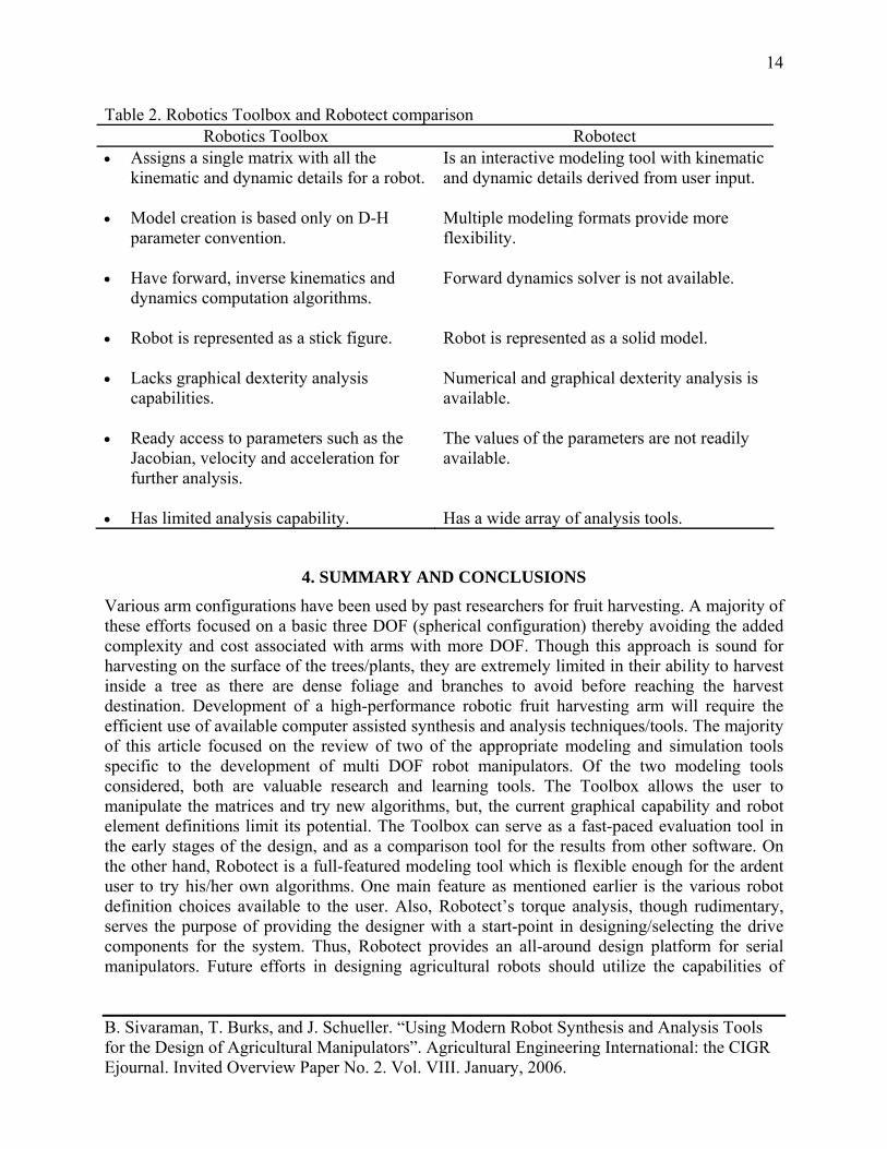
Table 2. Robotics Toolbox and Robotect comparison Robotics Toolbox Robotect
• Assigns a single matrix with all the kinematic and dynamic details for a robot.
• Model creation is based only on D-H
parameter convention. • Have forward, inverse kinematics and
dynamics computation algorithms. • Robot is represented as a stick figure. • Lacks graphical dexterity analysis
capabilities. • Ready access to parameters such as the
Jacobian, velocity and acceleration for further analysis.
• Has limited analysis capability.
Is an interactive modeling tool with kinematic and dynamic details derived from user input. Multiple modeling formats provide more flexibility. Forward dynamics solver is not available. Robot is represented as a solid model. Numerical and graphical dexterity analysis is available. The values of the parameters are not readily available. Has a wide array of analysis tools.
4. SUMMARY AND CONCLUSIONS
Various arm configurations have been used by past researchers for fruit harvesting. A majority of these efforts focused on a basic three DOF (spherical configuration) thereby avoiding the added complexity and cost associated with arms with more DOF. Though this approach is sound for harvesting on the surface of the trees/plants, they are extremely limited in their ability to harvest inside a tree as there are dense foliage and branches to avoid before reaching the harvest destination. Development of a high-performance robotic fruit harvesting arm will require the efficient use of available computer assisted synthesis and analysis techniques/tools. The majority of this article focused on the review of two of the appropriate modeling and simulation tools specific to the development of multi DOF robot manipulators. Of the two modeling tools considered, both are valuable research and learning tools. The Toolbox allows the user to manipulate the matrices and try new algorithms, but, the current graphical capability and robot element definitions limit its potential. The Toolbox can serve as a fast-paced evaluation tool in the early stages of the design, and as a comparison tool for the results from other software. On the other hand, Robotect is a full-featured modeling tool which is flexible enough for the ardent user to try his/her own algorithms. One main feature as mentioned earlier is the various robot definition choices available to the user. Also, Robotect’s torque analysis, though rudimentary, serves the purpose of providing the designer with a start-point in designing/selecting the drive components for the system. Thus, Robotect provides an all-around design platform for serial manipulators. Future efforts in designing agricultural robots should utilize the capabilities of
B. Sivaraman, T. Burks, and J. Schueller. “Using Modern Robot Synthesis and Analysis Tools for the Design of Agricultural Manipulators”. Agricultural Engineering International: the CIGR Ejournal. Invited Overview Paper No. 2. Vol. VIII. January, 2006.
15
such software tools. Careful analysis of robot parameters with these tools greatly reduces the development time and cost, and increases the accuracy of component selections.
5. ACKNOWLEDGMENTS
Research conducted at the University of Florida, Institute of Food and Agricultural Sciences, through funding provided by the Florida Department of Citrus.
Mention of commercial or proprietary products in this article is solely for the purpose of providing information and does not imply approval of a product over other available alternatives.
6. REFERENCES Asada, H. 1984. Dynamic analysis and design of robot manipulators using inertia ellipsoids. In: Proc. IEEE International Conference on Robotics and Automation 1, 94-102. Ceres, R., J. L. Pons, A. R. Jimenez, J. M. Martin, and L. Calderon. 1998. Design and implementation of an aided fruit-harvesting robot (Agribot). Industrial Robot 25 (5), 337- 346. Corke, P. I. 1996. A robotics toolbox for MATLAB. IEEE Robotics and Automation Magazine 3, 24-32. Craig, J. J. 2003. Introduction to robotics – mechanics and control. Pearson Education, Delhi, India. D’Esnon, A. G. 1985. Robotic harvesting of apples. In: Proc. Agri-Mation 1, 210-214. Chicago,
IL., 25-28 February. D’Esnon, A. G., G. Rabatel, R. Pellenc, A. Journeau, and M. J. Aldon. 1987. MAGALI: A self-propelled robot to pick apples. ASAE Paper No. 87-1037. St. Joseph, Mich. Harrell, R. C., P. D. Adsit, T. A. Pool, and R. Hoffman. 1988. The Florida robotic grove lab. ASAE Paper No. 88-1578. St. Joseph, Mich. Juste, F., and F. Sevila. 1991. Citrus: An European project to study the robotic harvesting of
oranges. In: Proc. 3rd International Symposium on Fruit, Nut, and Vegetable Harvesting Mechanization. Denmark-Sweden-Norway. Kassay, L., and D. C. Slaughter. 1993. Electrical, mechanical and electronic problems with the Hungarian apple harvester robot during the 1992 fall field tests. ASAE Paper No. 933088. St. Joseph, Mich.: ASAE. Kondo, N., M. Monta, and T. Fujiura. 1996. Basic constitution of a robot for agricultural use. Advanced Robotics 10 (4), 339-353. Nayar, H. D. 2002. Robotect: serial-link manipulator design software for modeling, visualization
and performance analysis. In: Proc. 7th International Conference on Control, Automation, Robotics and Vision 3, 1359-1364.
Parrish, E. A., Jr. and A. K. Goksel. 1977. Pictorial pattern recognition applied to fruit harvesting. Transactions of the ASAE 20 (5), 822-827. Pellenc, R., Montoya, J. L., D’Esnon, A. G., and Rombaut, M. 1990. Automated machine for detection and grasping of objects. U.S. Patent No. 4975016.
B. Sivaraman, T. Burks, and J. Schueller. “Using Modern Robot Synthesis and Analysis Tools for the Design of Agricultural Manipulators”. Agricultural Engineering International: the CIGR Ejournal. Invited Overview Paper No. 2. Vol. VIII. January, 2006.
16
Rabatel, G., A. Bourely, F. Sevila, and F. Juste. 1995. Robotic harvesting of citrus: State-of-art and development of the French Spanish Eureka project. In: Proc. International Conference
on Harvest and Post harvest Technologies for Fresh Fruits and Vegetables 95, 232-239. Sarig, Y. 1993. Robotics of fruit harvesting: A state-of-the-art review. Journal of Agricultural Engineering Research 54, 265-280. Yoshikawa, T. 1985. Manipulability of robotic mechanisms. The International Journal of Robotics Research 4 (2), 3-9.


![Advanced Synthesis of the DELTA Parallel Robot for a ... · The DELTA robot (see figure 1) is one of the most famous translational parallel manipulators [5,6,7]. However, as most](https://img.pdfslide.us/doc/110x75/60deb7bb75750716bc06342b/advanced-synthesis-of-the-delta-parallel-robot-for-a-the-delta-robot-see-figure.jpg)