Embed Size (px)
Citation preview

PATRAN 302 Exercise Workbook - Release 8.0 14-1
LESSON 14
Using Lists and Multi-Point Constraints
Objectives:
■ Use Lists to isolate and group nodes of interest.
■ Define MPC’s to convert solid translations into shell rotations.
■ Create a cyclic symmetric boundary constraint along the0 degree and 30 degree faces.

14-2 PATRAN 302 Exercise Workbook - Release 8.0

LESSON 14 Using Lists and Multi-Point Constraints
PATRAN 302 Exercise Workbook - Release 8.0 14-3
Model Description:In this exercise you will create MPC’s to attach the shellelements in your model to the solids. Shell and solidelements are incompatible. Solid elements providestiffness in only the three displacement directions for eachnode, while plate elements in P3/FEA provide stiffness tothree displacement directions and two rotations (in-planerotation is undefined). To connect the two dissimilarelements together requires MPC elements to account forthe rotational degrees of freedom defined by the shellelement.
The MPC equations you will use will create relationshipsbetween the nodes on the shell elements, and those on theupper and lower edges of the solids. You will use Lists togroup these nodes.
The MPC equations you will need to use and thejustification for each are as follows:
First the translational degrees of freedom are linearlyinterpolated to obtain the translation at the mid-plane ofthe solid. The translations of the plate edge is then setequal to that value.
FIGURE 1.
(EQ 1)
Z
R
θ shells0.4 top
bottom
Urshell
0.5 Urtop
Urbottom+( )=
14-4 PATRAN 302 Exercise Workbook - Release 8.0
(EQ 2)
(EQ 3)
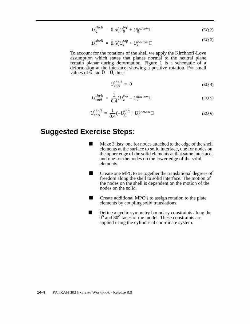
To account for the rotations of the shell we apply the Kirchhoff-Loveassumption which states that planes normal to the neutral planeremain planar during deformation. Figure 1 is a schematic of adeformation at the interface, showing a positive rotation. For smallvalues of θ, sin θ = θ, thus:
(EQ 4)
(EQ 5)
(EQ 6)
Suggested Exercise Steps:
■ Make 3 lists: one for nodes attached to the edge of the shell elements at the surface to solid interface, one for nodes on the upper edge of the solid elements at that same interface, and one for the nodes on the lower edge of the solid elements.
■ Create one MPC to tie together the translational degrees of freedom along the shell to solid interface. The motion of the nodes on the shell is dependent on the motion of the nodes on the solid.
■ Create additional MPC’s to assign rotation to the plate elements by coupling solid translations.
■ Define a cyclic symmetry boundary constraints along the 0o and 30o faces of the model. These constraints are applied using the cylindrical coordinate system.
Uθshell
0.5 Uθtop
Uθbottom+( )=
Uzshell
0.5 Uztop
Uzbottom+( )=
Urotrshell
0=
Urotθshell 1
0.4------- Uz
topUz
bottom–( )=
Urotzshell 1
0.4------- U– θ
topUθ
bottom+( )=

LESSON 14 Using Lists and Multi-Point Constraints
PATRAN 302 Exercise Workbook - Release 8.0 14-5
Files:
All the files used in this exercise are listed below. Each listingincludes the file, where it originated, its format (text/binary) andsummary information as to how it relates to this exercise.
File Supplied/Created Description
mpc.db Created in ex2 This is a PATRAN database (binary) createdin Exercise 2. The geometry for the modelwas created in Exercise 2. The mesh for themodel was generated in Exercise 6. Finally,multi-point constraints will be created inExercise 7.
Exercise Procedure:
1. Open database mpc.db.
2. Create a list of nodes along the edge of the shellelements at the solid to surface interface.
Click on Tools in the Control Panel, select List/ Create...from the pull-down menu and then select the following:
The nodes along the edge of the shell are at a radius of 6.2units and an axial location of 2 units. To group the nodesthat share these coordinates, change the Refer. CoordinateFrame to the cylindrical coordinate frame in your modeland search on the above listed coordinate values.
Tools/List/Create...
Model:
Object:
Method:
Attribute Coord Value
Refer. Coordinate Frame Coord 1
■ R
■ Z
R 6.2
Creating Lists for interface nodes
FEM
Node
Attribute

Creating Lists for Bottom Nodes
14-6 PATRAN 302 Exercise Workbook - Release 8.0
3. Create a list to reference nodes on the bottom of thesolid.
You now have two lists but we need to use three to definethe MPC’s. To create the third list, we need a list ‘c’.
4. Create a list to reference nodes on the top of thesolid.
Click on Tools/ List in the Control Panel and select Boolean... fromthe pull-down menu.
You will make a list c that duplicates the current contents of list b.You will use list c when you need to reference nodes on the bottomof the solids. You will create a new list b referencing the nodes onthe top edge of the solid for your third list. You will use list b whenyou need to reference nodes on the top of the solids.
In order to move the contents of the current list b into list c, on theBoolean List form, click on the icon for B-A.
At this point, ‘listc‘ contents and ‘listb‘ contents should be identical:the nodes on the bottom of the solids.
On the List B form, click Clear.
Z 2
Target List ◆ “A”
Apply
Target List ◆ “B”
R 6.0
Z 2.0
Apply
Tools/ List/Boolean...
Clear
Creating Lists for Bottom Nodes
Creating Lists for Top Nodes
A B
B - A

LESSON 14 Using Lists and Multi-Point Constraints
PATRAN 302 Exercise Workbook - Release 8.0 14-7
On the Create List form, enter the following to create list b:
You now have 3 lists: list ‘a’ references the nodes at the solid/shelledge of the shell elements, list b references the nodes at the top edgeof the solids along the interface, and list ‘c’, the nodes along thebottom edge of the solids.
5. Create a MPC to tie together the translational degrees offreedom along the shell to solid interface.
The first MPC you will create will tie together thetranslational degrees of freedom along the shell to solidinterface as shown in Equation 1 through Equation 3 onpage -4 . The dependent nodes will be those in list a, whichare associated with the quad elements.
Click on Define Terms... and a Define Terms Menu willshow up on the screen. Enter the following (remember toenclose PCL variables in backquote (i.e. “ ‘ “) as opposedto single quote (“ ’ “) or double quotes (“ “ “) whenentering the Node List):
R 6.4
Z 2.0
Apply
◆ Finite Elements
Action:
Object:
Method:
Constant Term 0
Define Terms
◆ Create Dependent
Node List ‘lista‘
DOFs UXUYUZ
Creating MPC’s
Create
MPC
Explicit
Creating MPC’s
14-8 PATRAN 302 Exercise Workbook - Release 8.0
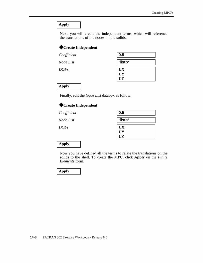
Next, you will create the independent terms, which will referencethe translations of the nodes on the solids.
Finally, edit the Node List databox as follow:
Now you have defined all the terms to relate the translations on thesolids to the shell. To create the MPC, click Apply on the FiniteElements form.
Apply
◆ Create Independent
Coefficient 0.5
Node List ‘listb‘
DOFs UXUYUZ
Apply
◆ Create Independent
Coefficient 0.5
Node List ‘listc‘
DOFs UXUYUZ
Apply
Apply
LESSON 14 Using Lists and Multi-Point Constraints
PATRAN 302 Exercise Workbook - Release 8.0 14-9
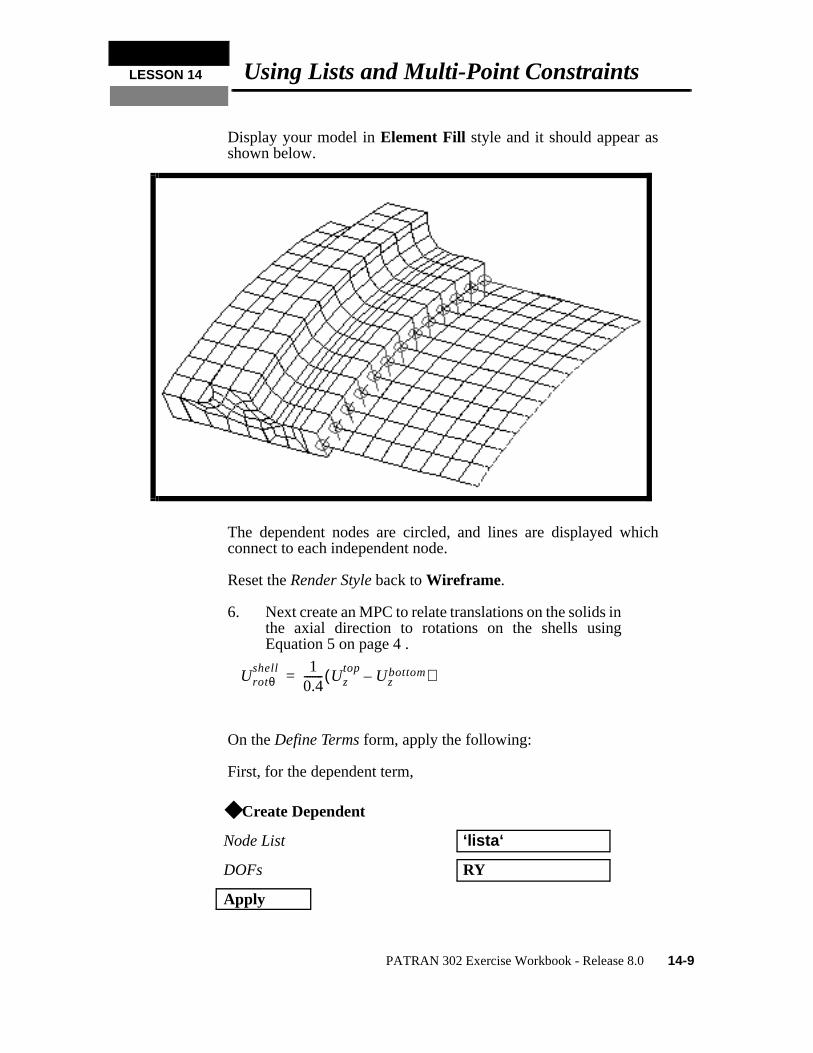
Display your model in Element Fill style and it should appear asshown below.
The dependent nodes are circled, and lines are displayed whichconnect to each independent node.
Reset the Render Style back to Wireframe.
6. Next create an MPC to relate translations on the solids inthe axial direction to rotations on the shells usingEquation 5 on page 4 .
On the Define Terms form, apply the following:
First, for the dependent term,
◆ Create Dependent
Node List ‘lista‘
DOFs RY
Apply
Urotθshell 1
0.4------- Uz
topUz
bottom–( )=
Creating MPC’s
14-10 PATRAN 302 Exercise Workbook - Release 8.0
Now, for the independent terms,
and
Now you have defined all the terms, click Apply on the FiniteElements form.
7. Create the final MPC using Equation 6 on page 4 .
First, for the dependent term,
Now, for the independent terms,
◆ Create Independent
Coefficient ‘1/.4‘
Node List ‘listb‘
DOFs UZ
Apply
Coefficient ‘-1/.4‘
Node List ‘listc‘
DOFs UZ
Apply
Apply
◆ Create Dependent
Node List ‘lista‘
DOFs RZ
Apply
◆ Create Independent
Coefficient ‘-1/.4‘
Node List ‘listb‘
DOFs UY
Urotzshell 1
0.4------- U– θ
topUθ
bottom+( )=

LESSON 14 Using Lists and Multi-Point Constraints
PATRAN 302 Exercise Workbook - Release 8.0 14-11
and
Now you have defined all the terms, click Apply on the FiniteElements form.
8. Change the view of your model as follows:
Select the side view icon from the toolbar
9. Finally, construct the axisymmetric constraint. Theseconstraints will be applied to the R-Z faces at Theta = 0degrees and Theta = 30 degrees. In order to properlycreate a symmetric boundary condition, constraint ofone displacement and the other two rotations.
First, construct the translation constraint in theta direction asfollows:
Apply
Coefficient ‘1/.4‘
Node List ‘listc‘
DOFs UY
Apply
Apply
◆ Load/BCs
Action:
Object:
Method:
New Set Name Theta_Constraint
Construct Constraint in Theta Direction
Create
Displacement
Nodal

Construct Constraint in Theta Direction
14-12 PATRAN 302 Exercise Workbook - Release 8.0
Click on Input Data to open up another menu and then enter thefollowing:
Click on Select Application Region to open up another menu andthen select the nodes as shown below:
(You may want to use the polygonal click method to select the nodesat the left end.)
Input Data
Translations <T1 T2 T3> < ,0, >
Rotations<R1 R2 R3> <0, ,0>
Analysis Coordinate Frame Coord 1
OK
Select Application Region
Geometry Filter FEM
Select Nodes Node 1:52 54 56 57 69 169:176 684:729 (The node entities may not be the same on your model)
Add
OK
Select only end nodes
LESSON 14 Using Lists and Multi-Point Constraints
PATRAN 302 Exercise Workbook - Release 8.0 14-13
Press Apply in the Load/BCs form.
Change the view of your model as follows:.
Click on the Iso 1 View icon in the toolbar
To get a better view of the boundary conditions on the model, changethe display as follows:
and
Apply
Display/Finite Elements ...
◆ Free Edges
Apply
Cancel
Display/Load/BC/Elem. Props ...
Vectors/Filters...
❐ Show Result Values
❐ Show LBC/El. Prop Values
Apply
Cancel
Construct Constraint in Z-Direction
14-14 PATRAN 302 Exercise Workbook - Release 8.0
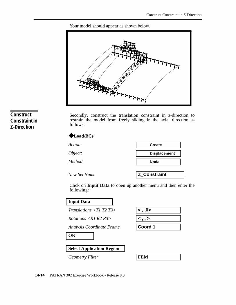
Your model should appear as shown below.
Secondly, construct the translation constraint in z-direction torestrain the model from freely sliding in the axial direction asfollows:
Click on Input Data to open up another menu and then enter thefollowing:
◆ Load/BCs
Action:
Object:
Method:
New Set Name Z_Constraint
Input Data
Translations <T1 T2 T3> < , ,0>
Rotations <R1 R2 R3> < , , >
Analysis Coordinate Frame Coord 1
OK
Select Application Region
Geometry Filter FEM
Construct Constraint in Z-Direction
Create
Displacement
Nodal
LESSON 14 Using Lists and Multi-Point Constraints
PATRAN 302 Exercise Workbook - Release 8.0 14-15
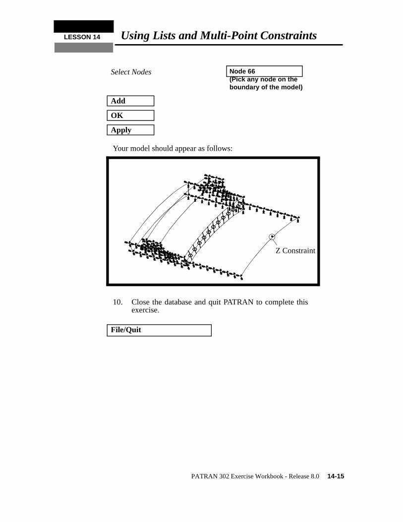
Your model should appear as follows:
10. Close the database and quit PATRAN to complete thisexercise.
Select Nodes Node 66(Pick any node on the boundary of the model)
Add
OK
Apply
File/Quit
Z Constraint

Construct Constraint in Z-Direction
14-16 PATRAN 302 Exercise Workbook - Release 8.0