Embed Size (px)
Citation preview

1
Using Insulated Metal Panels as Part of a Building Enclosure Energy Retrofit
November 11, 2011
Prepared by: Building Science Corporation
Prepared for: Kingspan Insulated Panels Ltd.

2
Contents
Introduction ............................................................................................................................................................................... 4
Exterior Insulation ..................................................................................................................................................................... 4
Building Appearance ............................................................................................................................................................. 4
Water Management ............................................................................................................................................................... 4
Interior Constraints ................................................................................................................................................................ 5
Enclosure Control Functions ..................................................................................................................................................... 5
Water management ............................................................................................................................................................... 6
Vapor Management ............................................................................................................................................................... 6
Thermal Performance ............................................................................................................................................................ 7
Exterior Insulation Strategies .................................................................................................................................................... 7
Conventional ......................................................................................................................................................................... 7
EIFS ...................................................................................................................................................................................... 8
IMP ........................................................................................................................................................................................ 9
Use of IMP as exterior insulation and cladding ....................................................................................................................... 10
IMP’s as a complete enclosure ........................................................................................................................................... 10
As an insulated cladding with back up WRB ....................................................................................................................... 11
System design considerations ................................................................................................................................................ 13
Window integration .............................................................................................................................................................. 13
Upper roof to lower wall details ........................................................................................................................................... 18
Upper wall to lower roof details ........................................................................................................................................... 19
Wall to foundation details .................................................................................................................................................... 21
Compartmentalization behind the panels ............................................................................................................................ 21
Uneven back up wall construction ....................................................................................................................................... 23

3
List of Figures
Figure 1: Building enclosure functions ...................................................................................................................................... 5
Figure 2: Schematic of the "perfect wall" .................................................................................................................................. 6
Figure 3: Wall assembly with dedicated WRB/air barrier membrane, exterior insulation, and cladding system........................ 8
Figure 4: Wall assembly with EIFS cladding ............................................................................................................................. 9
Figure 5: Wall assembly with IMP as complete enclosure system .......................................................................................... 10
Figure 6: Condensing surface location and effects of increase panel thickness on condensation potential in the wall assembly ................................................................................................................................................................................. 11
Figure 7: Wall assembly with IMP used as an insulated cladding ........................................................................................... 12
Figure 8: Condensing surface location and effects of increase panel thickness on condensation potential in the wall assembly ................................................................................................................................................................................. 13
Figure 9: Integration of aluminum small box curtainwall frame with IMP used as the complete wall enclosure system .......... 14
Figure 10: Integration of aluminum storefront frame with IMP used as the complete wall enclosure system.......................... 15
Figure 11: Integration of aluminum small box curtainwall frame with IMP used as an insulated cladding .............................. 16
Figure 12: Integration of aluminum storefront frame with IMP used as an insulated cladding ................................................ 17
Figure 13: Upper roof to lower wall connection with IMP used as the complete wall enclosure system ................................. 18
Figure 14: Upper roof to lower wall connection with IMP used as an insulated cladding ........................................................ 19
Figure 15: Upper wall to lower roof connection with IMP used as a complete wall enclosure system .................................... 20
Figure 16: Upper wall to lower roof connection with IMP used as an insulated cladding ........................................................ 21
Figure 17: Compartmentalization behind IMP ......................................................................................................................... 22
Figure 18: Compartmentalization through the use of an exterior air barrier membrane .......................................................... 23
Figure 19: Adjustable IMP attachment system ........................................................................................................................ 23

4
Introduction The existing residential and commercial building stock represents a significant portion of the energy consumption used in North America. In the United States, the building stock consumed roughly 40% of the primary energy used in 2008 (DOE/EIA 2008). New construction represents only a small fraction of the total building stock in the country. While the adoption of energy codes in many states has helped drive towards lower energy use buildings, the existing building stock remains, for the most part, untouched.
Current trends are looking at ways to improve the performance of existing buildings as a means to breathe new life into these older structures. These performance improvements can take a wide variety of forms from building weatherization, which looks to make improvements to the building to better the performance wherever practical, to deep energy retrofits (DER), that attempt to bring an existing building beyond current standards of new construction performance. A DER in essence creates a new building that is designed to perform well into the future by leveraging the physical asset of the existing building.
This paper looks to examine the benefits of the addition of exterior insulation as part of a DER, with a focus on the use of insulated metal panels (IMP), as a means to improve the performance of existing building enclosures.
Exterior Insulation A major component of DER’s are often upgrades to the building enclosure. In the past, retrofits of existing buildings typically involved the filling of framed cavity walls with insulation; however, the amount of effective thermal resistance that could be added was limited by the existing stud cavity depth (wood frames walls) or strapping depth (common for mass masonry walls), the insulation material used (commonly fiberglass/mineral fiber or cellulose), and the amount of thermal bridging present from the wood framing. In order to meet higher performance goals, other insulation strategies are often required. The addition of insulation to the exterior of existing buildings has been demonstrated to be an effective means to overcome these limitations and provide higher effective R-values for building wall assemblies. The benefits of this approach extend beyond just added thermal resistance; benefits of increased building durability and air tightness are often also realized.
From a building science perspective, the recommended location for insulation is to the exterior of the structure. The practice of placing the exterior insulation as well as the water management and air barrier control layers to the exterior of the wall structure has been described as the “perfect wall”. This approach is not new; it was identified in the 1960’s by researches in Canada that outlined the benefits of this approach on buildings. The placement of insulation to the exterior of the structure has many benefits including better continuity and overall thermal performance, reduced thermal stress on the structure, and better interstitial condensation control. The placement of insulation to the exterior in a retrofit application can also leverage insulation that may be already in the wall assembly, thereby adding to the overall thermal resistance rather than removing and replacing.
It should be noted that it is not always possible or practical to insulate on the exterior, and sometime other strategies need be considered. In certain circumstances, maintaining the exterior appearance of the building is a requirement (in historic buildings) or desired (for an aesthetically appealing building). In other circumstances, the potential cost of installing insulation on the exterior can be problematic. Since the strategy requires not just the cost of the insulation, but also the cost of new cladding, the cost is often higher than other insulation retrofit approaches.
Building Appearance
Insulating on the exterior fundamentally requires change to the exterior appearance. The amount of change might be insignificant depending on the design. It is possible with even significant amounts of exterior insulation added to the exterior, that the original appearance or at minimum design aesthetic can be maintained. On the other end of the spectrum adding exterior insulation (and by extension a re-clad of the building) to buildings that could be considered aesthetically challenged, can create an opportunity for a significant improvement to the building appearance.
Water Management
Buildings that may be strong candidates for exterior insulation retrofits would be buildings that have existing water management concerns. It is not uncommon at the time that rehabilitation of a building is decided, that that there are problems with existing performance of the building’s exterior rain water management. In fact, in many cases it is this poor performance that is the catalyst that initiates a retrofit project. Situations such as these can help to reduce the capital cost of the energy performance upgrade, by incorporating the energy and cost that may have been needed to repair or rehabilitate existing water management strategies into the cost of the exterior insulation strategy.
5
Interior Constraints
Disruption to interior spaces can be a significant concern during a retrofit if the building is intended to be occupied over the course of the renovation. At the extreme end of the spectrum, residential occupied rehabilitation projects may have strict timelines requiring all of the interior work in a certain area to be completed in a single day or less. Exterior work typically has more freedom since it can often be completed without direct interference with the building occupants. This can help offset other potential scheduling costs that may arise due to temporary relocation of offices of living units.
Useable floor area can also drive the considerations. As discussed earlier, the structure of the building will limit the amount of insulation that can be applied within the existing building elements. For most retrofits with goals of significant thermal improvements, additional insulation must either be added to the interior or the exterior of the building. If added to the interior, the added thickness of the wall assembly will reduce the overall useable square footage of the building. This may or may not be a big consideration, but could drive the decision making if already small spaces are threatened to be made smaller.
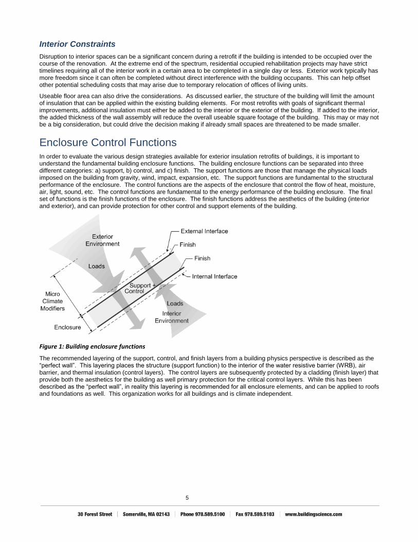
Enclosure Control Functions In order to evaluate the various design strategies available for exterior insulation retrofits of buildings, it is important to understand the fundamental building enclosure functions. The building enclosure functions can be separated into three different categories: a) support, b) control, and c) finish. The support functions are those that manage the physical loads imposed on the building from gravity, wind, impact, expansion, etc. The support functions are fundamental to the structural performance of the enclosure. The control functions are the aspects of the enclosure that control the flow of heat, moisture, air, light, sound, etc. The control functions are fundamental to the energy performance of the building enclosure. The final set of functions is the finish functions of the enclosure. The finish functions address the aesthetics of the building (interior and exterior), and can provide protection for other control and support elements of the building.
Figure 1: Building enclosure functions
The recommended layering of the support, control, and finish layers from a building physics perspective is described as the “perfect wall”. This layering places the structure (support function) to the interior of the water resistive barrier (WRB), air barrier, and thermal insulation (control layers). The control layers are subsequently protected by a cladding (finish layer) that provide both the aesthetics for the building as well primary protection for the critical control layers. While this has been described as the “perfect wall”, in reality this layering is recommended for all enclosure elements, and can be applied to roofs and foundations as well. This organization works for all buildings and is climate independent.

6
Figure 2: Schematic of the "perfect wall"
While the “perfect wall” describes the optimum solution for enclosure design, variations on the approach can also provide very good performance. For some systems, various control layers and functions can be combined into single elements. As an example, it is common for the WRB and air barrier to be combined into a single material such as a building wrap with taped and sealed joints, a self adhered membrane, or liquid applied membrane. In other cases, even the thermal insulation can be part of the system such as with the use of exterior closed cell spray polyurethane foam which can provide the water management, air flow control, vapor management and thermal insulation. Even beyond this, other systems such as EIFS and IMP’s include the cladding as part of a single system with the thermal insulation and possibly air barrier and WRB.
When evaluating a system for performance, it is important to understand which materials are providing which of the building enclosure functions. Once the materials and the associated functions are identified, the design of the system must ensure that continuity of the functions are maintained within the assembly, as well as at interfaces with other enclosure elements.
Water management
There are multiple ways that a building enclosure assembly will manage exterior rain water loads. The methods can be simply broken out into drained systems, barrier systems, and mass systems.
Mass systems are the oldest form of water management. A mass enclosure relies on the ability of the structure (typically stone or masonry) to absorb and hold water for a time without any detrimental effects and dry out at a later date.
Drained systems have had the best track record of performance as the primary water managed layer is protected by an outer finish layer (cladding) and is drained back to the exterior (and in some cases ventilated). In the most simple of terms, a drained assembly functions by a means of load reduction. The cladding is not designed to be a complete barrier, though it is intended to shed the majority of the incident rain. By reducing the load on the WRB behind the cladding by 90% to 99%, the potential risks of water infiltration are also reduced by a similar amount. The drainage and ventilation provide the drying of the assembly.
Barrier systems have not had as strong a history. Some systems can be made to function very well, however; control and construction tolerance must be very high. Assemblies such as structural glazed curtain walls are an example of a barrier enclosure system that can be designed to function well. The primary concern with barrier systems are that if water should penetrate past the exterior surface, there is no provision for drainage back to the exterior.
A hybrid of barrier and drained assemblies are barrier systems with drained joints. Examples of these types of systems are precast concrete panels with a two stage drained joint and IMP’s. Barrier systems with water managed and drained joints function more closely to drained systems then to barrier systems.
Vapor Management
Vapor management in an enclosure assembly is typically provided by controlling the flow of vapor through materials and/or by controlling condensing surface temperatures to prevent the possibility of moisture accumulation in the assemblies. The condensing temperature is commonly referred to as the “dewpoint” temperature in the wall assembly. In order to prevent condensation, the temperature of surfaces within the wall assembly must be maintained at a temperature above the dewpoint temperature of the air that is coming in contact with the surface. The decision for how to manage vapor flow is

7
complicated and will depend on climate (interior and exterior) conditions. As a general rule of thumb, assemblies in the cold climates try to limit outward vapor movement, while assemblies in hot humid climates try to limit inward vapor movement.
Fundamentally however, no problems will occur, provided that moisture is not able to condense within the enclosure assemblies, or reach elevated relative humidity levels for prolonged periods of time. For this reason, exterior insulation approaches significantly reduce the risk of moisture accumulation problems by lowering or eliminating the risk of condensation occurring within enclosure assemblies. The use of exterior insulation shifts the location of potential condensation to a spot exterior of the structure and water resistive barrier. Since the potential is now exterior of the support and control elements, it no longer creates a concern for moisture accumulation or deterioration of building materials within the wall assembly.
Thermal Performance
Actual thermal performance of a building is based on the effective thermal resistance of the assemblies. The effective thermal resistance takes into account not only the thermal resistance of the insulation, but all of elements in the enclosure assembly. The impact of thermal bridging of insulation layers in cavity walls has been well documented. It is not uncommon for reductions of up to 50% for wood frames, and 75% for steel framed buildings. While nominal values of R-13 for 2x4 framing and R-19 for 2x6 framing are commonly used, the actual in situ performance of these systems is much lower. Exterior insulation strategies can be applied with minimal thermal bridging which can help to increase the performance of the wall assemblies to near the nominal rated value of the thermal insulation. Care must be taken however, as cladding attachment systems or other structural penetrations can lead to significant performance reductions if not properly considered or designed.
Exterior Insulation Strategies Providing thermal insulation to the exterior of an existing structure can be provided by several different means. The benefits of this approach extend beyond just added thermal resistance; benefits of increased building durability and air tightness are often also realized. Deciding which strategy will be most appropriate for the building retrofit project has several facets to consider.
Conventional
The typical approach is to use distinct materials (or elements) for all of the control layers, and assemble them into an enclosure system. This approach provides a wide range of options in design and material choices. The system can be designed with any number of different insulation types and layering of materials and thicknesses. Also, the choice of cladding is completely independent of the other control layers behind it, providing the greatest flexibility in final appearance of the system.

8
Existing structure WRB/Air barrier membrane Cladding support system Insulation Cladding
Figure 3: Wall assembly with dedicated WRB/air barrier membrane, exterior insulation, and cladding system
This flexibility can also create possible draw backs, in that more care and knowledge must go into the design. While the choice of the cladding system is broad, it must be attached back to the structure by some means. A conflict often exists between the performances of the cladding attachment system to the performance of the thermal insulation. The simple use of Z-girt as the primary means of providing a standoff and space between the structural wall and the cladding can have severely detrimental impacts on the thermal performance of the insulation. On the other hand, providing a support system with only minimal thermal bridging seems to create a design problem for most engineers and architects.
Another important factor to consider is the requirement for fire rated assemblies. Depending on the type on construction, the exterior wall assemblies may need a fire rating classification. While exterior insulation strategies are becoming more popular, many of the configurations do not have currently have UL ratings. It is important to check with local building code officials and product manufacturers to ensure the proposed design meets the fire safety requirements of the area.
EIFS
EIFS is another means by which insulation can be applied to the exterior of the building. EIFS is a relatively low cost insulation and cladding system compared to other conventional approaches, and has many advantages to its use including low weight and appearance. While the general appearance of EIFS emulates cementitious stucco, the ability to create intricate and custom profiles allows for a variety of architectural detailing within the stucco aesthetic.

9
Existing structure WRB/Air barrier membrane (typically trowel applied) Vertical bands of adhesive EPS Insulation Synthetic Stucco Lamina
Figure 4: Wall assembly with EIFS cladding
EIFS traditionally uses expanded polystyrene foam as the substrate for the finish. The thermal resistance of EPS is nominally R-4/inch and is on the low end compared to other common exterior insulation materials being used. Depending on the thermal performance goals of the project, the overall thickness of the wall may become an issue.
Issues have come up regarding insurance premiums being higher for EIFS system compared to other enclosure systems. While not certain, the author speculates that the higher premiums are due (at least in part) to past performance issues with EIFS claddings. Problems of water infiltration, material deterioration and mold growth occurred due to poor water management design of barrier EIFS claddings. Modern systems have addressed many of these past concerns, with many water managed and drained EIFS systems being available. While the present systems may provide significant improved performance over past system, economic issues relating to insurance still exist.
With EIFS, some manufacturers have developed and tested systems to meet certain fire code requirements. These systems may require special materials and detailing which could increase the overall cost of the system. Not all EIFS have been tested and approved for fire resistance however, so it is important to identify the requirements early on in the design process.
IMP
Another option for providing exterior insulation is through the use of Insulated Metal Panels (IMP). IMP’s are typically formed with inner and outer metal skins bonded together with an insulating foam core. IMP’s are designed to function as a complete enclosure combining all of the finish and control layers into a single system. The cladding, water management, air tightness, vapor management, and insulation are all provided by the panel system design. This can provide significant advantages to the designer as a sole source approach to the opaque wall enclosure can be used.
Other benefits to the system are the higher R-value to thickness ratio. With IMP’s having a thermal resistance rating of over R-7 per inch (even upwards of R-8/inch), high amounts of thermal resistance can be achieved with a comparatively low thickness being added to the exterior of the existing building. Thermal bridging is minimized as the support structure for the panel is to the interior of the insulation and the connection is made through screw or bolt connections through the panels. Since the panel also functions as the cladding, thicknesses can be further minimized by eliminating the need for space taken up by the cladding attachment system and the cladding itself.
There are many profiles, textures, and colors available as well as infinite options for panel organization and color combinations, allowing for plenty of creative design. Also, the finish is a high quality low maintenance finish providing a clean and polished look to the building.
Since IMP’s are designed as a complete enclosure system, most of the products and systems have been tested and have a fire resistance rating. This can reduce the need for further analysis and potentially very costly testing (such as full scale assembly burn tests).

10
Use of IMP as exterior insulation and cladding When looking to use an IMP in an exterior building enclosure retrofit there are two primary options for system configuration. The panel can be configured to function as a complete enclosure combining all of the control layers into the panel system itself. This is how the panels are designed to function in new construction and the recommended approach for the system if it can meet all the program requirements of the building. A second approach is to use the panel in essence as an insulated cladding system that will provide the cladding (rain screen), and insulation, but the water resistive barrier, air barrier are provided by other elements. This approach may sometimes be warranted due to existing conditions and project limitations that will be discussed in more detail later in this document.
IMP’s as a complete enclosure
Using the IMP as an enclosure “overclad” is the recommended approach if it can be accomplished. This approach installs the panels following the manufacturers’ standard installation details and combines all of the enclosure control layers into one system. Fundamental to the IMP design is that the primary control layer for water management and air flow control is at the interior surface of the IMP. All materials inboard of the IMP are inside the new enclosure and should be considered as such (this includes any cladding system that may be left in place as part of the project).
Adjustable cladding support system (designed to allow for variations in the back-up wall construction) Insulated Metal Panel (Installed as a complete enclosure) Existing structure
Figure 5: Wall assembly with IMP as complete enclosure system
Water management is through a two stage pressure moderated and drained joint system. Key to the performance is in the interconnection of the panels at horizontal and vertical joints, as well as at interfaces with other enclosure elements such as windows. Given that the IMP is now the complete enclosure, other elements such as window systems need to be integrated into the panel and not into the old wall system. This will almost certainly require removal and replacement (or re-installation in some rare circumstances) of the window systems as part of the project.
Overall air tightness is maintained at the inner sealant joints installed as part of the system design. Similar to the water management system, all air barrier connections need to be made to maintain continuity with the interior side of the panel and the associated inner seal joint between the panels.
Vapor management is maintained through the fundamental nature of the panel. Inward vapor drive is controlled by the impermeable nature of the IMP exterior skin. Outward vapor control and condensation resistance is maintained through control of the condensing surface temperature. If the panel is installed over a previously un-insulated building, then there would be no concerns of interstitial condensation in any climate zone for any commonly available panel thickness. If the existing building is insulated to some degree, or if there is a plan to use a hybrid approach that combines other insulation products with the IMP to achieve the total thermal resistance for the assembly then simple dewpoint analyses can be completed using the interior surface of the IMP as the condensing surface location. The process can be further simplified by looking at current code requirements vapor control. Currently in the 2009 IRC Table R601.3.1 Class III Vapor Retarders and the 2009 IBC Table 1405.3.1 Class III Vapor Retarders, outlines under what conditions a Class III vapor retarder (equivalent to latex or enamel paint on drywall) can be used. The table has provision for amounts of exterior insulation by climate zone

11
compared to wall assemblies needed for condensation control. While the table is limited to framed-wall construction with cavity fill insulation, it does put into context the required exterior insulation amounts that are need for condensation control. In the worst case scenario of climate zone 8 with an interior thermal resistance equivalent to R-19, the required exterior insulation is R-15. With the high thermal resistance of IMP’s, a 2” thick panel would be required to provide adequate thermal resistance for condensation control. Since most IMP start at a 2” thick panel, only in rare cases is there a risk of interstitial condensation within the wall assembly when a building is clad with an IMP. If a potential does exist, increasing the IMP thickness will raise the condensing surface temperature and further reduce the risk of condensation.
Case 1
Case 2
Figure 6: Condensing surface location and effects of increase panel thickness on condensation potential in the wall assembly
As an insulated cladding with back up WRB
An alternate enclosure retrofit approach utilizes an IMP as an insulated cladding with a secondary water resistive barrier and air barrier behind the panels. While this would not be the first choice in the configuration of the system, it can be a good choice in certain circumstances such as when all of the work is being completed from the exterior but compartmentalization of the interior spaces in required. Fundamental to the design is that the primary control layers for water management and air flow control are at some location behind the IMP, and all materials inboard of these control layers are considered interior of the building. The IMP functions as the cladding system and primary thermal resistance layer. Continuity of the thermal insulation must be maintained between the control layers and the back of the IMP.
Condensing surface
Condensation will not occur provided dewpoint temperature of the interior air is below the temperature at the condensing surface
Outside Temperature
Inside Temperature
Max dewpoint (Case 2)
Max dewpoint (Case 1)

12
WRB/Air barrier membrane Adjustable cladding support system (designed to allow for variations in the back-up wall construction) Mineral fiber infill insulation (installed to maintain continuity of the thermal resistance between the air barrier and the back of the IMP) Insulated Metal Panel (Installed as an insulated cladding assembly) Existing structure
Figure 7: Wall assembly with IMP used as an insulated cladding
Water management is through a dedicated WRB installed behind the IMP. Since the IMP function is primarily as a cladding, all flashings and interfaces with the other enclosure elements must be connected to the WRB. If there is an effective WRB already in existence and it is desired to be maintained, it may be possible for windows and other elements to be left in place. Also, since a water management system is installed behind the panel system, many of the sealants typically installed in the IMP system for water management and air tightness may not be as critical and could be considered to be omitted in some cases.
While the mineral fiber insulation will reduce the potential for drainage, concerns of water retention in the system are minimal. If a large amount of water is able to get past the exterior IMP, the majority of the water will drain out due to gravity overcoming the retention forces in the system. The remaining moisture will be able to redistribute laterally due to the vapor open nature of the mineral fiber insulation. The drying potential can be further increased by allowing the system to dry to the interior (this can only be done if all of the materials inboard of the WRB/air barrier membrane are vapor open and would not be recommended if interior vapor barrier or low permeability materials are currently in the existing wall assembly). In addition, the materials used in the system are all non-moisture sensitive and can tolerate exposure to liquid water for periods of time.
The air flow control is maintained through a dedicated air barrier system. The air barrier must be continuous with all other enclosure elements. The recommended location is to provide the air barrier, exterior of the existing structure. Often the air barrier can be integrated with the WRB system either in part, or by using a single material that is able to perform both functions (such as with most self-adhered and liquid applied membrane systems).
Inward vapor drive is predominantly controlled by the impermeability of the IMP, however, due to the potential for air movement behind the panels, alternate control layers could be at the WRB location (such as through the use of a vapor impermeable SBS membrane). Alternately, the enclosure can be designed based on a vapor “flow through approach”, to allow for unrestricted diffusion inwards (ie. no interior Class I or Class II vapor retarder) and a vapor permeable WRB and air barrier can be used (this is not recommended if interior vapor barriers or low permeability materials are currently in the existing wall assembly).
Outward vapor control is by controlling the condensing surface temperature. Unlike the first approach (using the IMP as the complete enclosure), the condensing surface in this assembly is behind the WRB and air barrier. This configuration typically provides even less risk of condensation accumulation in the assembly.

13
Case 1
Case 2
Figure 8: Condensing surface location and effects of increase panel thickness on condensation potential in the wall assembly
System design considerations To properly design and configure the system as part of a building retrofit many considerations must be taken into account when choosing the approach. Once the approach is chosen, all of the enclosure connection details must be developed based on that strategy to ensure continuity of the complete enclosure through all elements such as roofs, foundations, windows. The following section outlines some concept details developed to illustrate intent of how the systems can be connected to other enclosure elements. It is acknowledged that the following is not an exhaustive list, and since every retrofit project will have it’s own specific boundary conditions, that not all possible options are represented.
Window integration
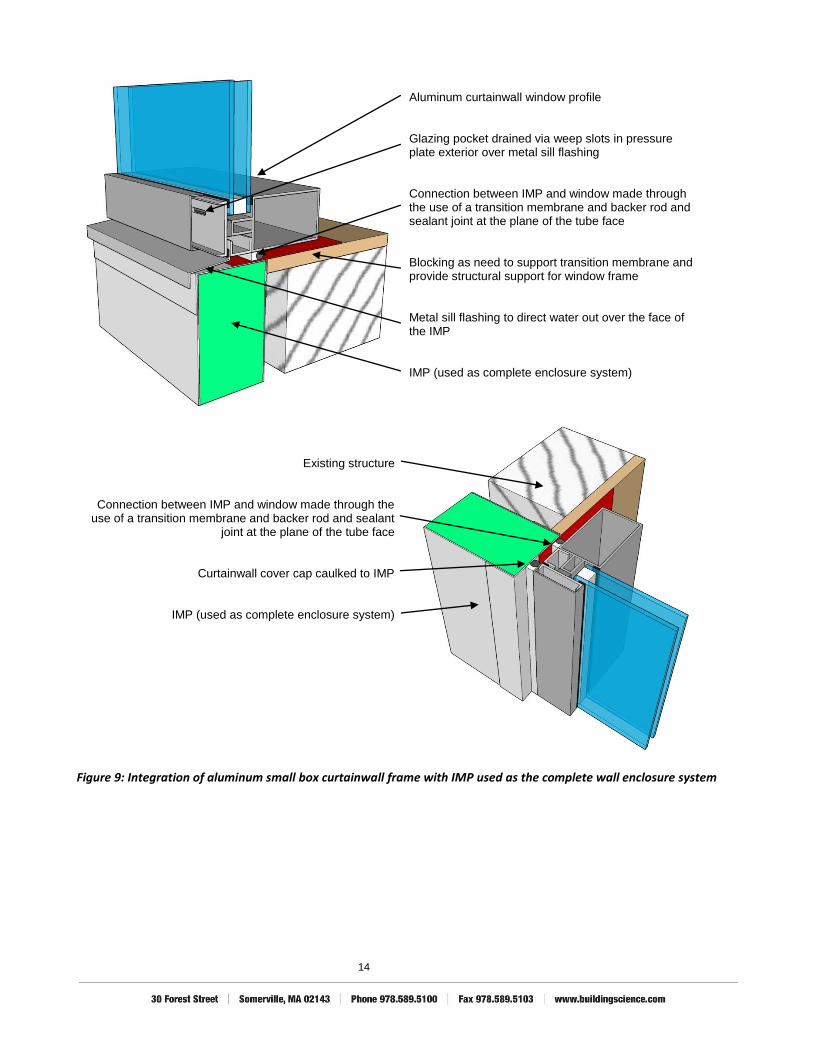
Window are recommended to be installed in a water managed and drained opening. For residential style punched windows and commercial storefront assemblies, providing a waterproofed and drained space between the window and rough opening is recommended. For small box curtainwall profiles, the details can be slightly different provided a waterproof seal is provided at the tube face and, the glazing pocket that is formed by the screw spline is drained to the exterior. For IMP systems used as the complete enclosure, the windows should be integrated with the panel. For IMP systems used as an insulated cladding, the integration must be done at the rough of the existing wall assembly.
Condensing surface
Condensation will not occur provided dewpoint temperature of the interior air is below the temperature at the condensing surface
Outside Temperature
Inside Temperature
Max dewpoint (Case 2)
Max dewpoint (Case 1)
14
Aluminum curtainwall window profile Glazing pocket drained via weep slots in pressure plate exterior over metal sill flashing Connection between IMP and window made through the use of a transition membrane and backer rod and sealant joint at the plane of the tube face Blocking as need to support transition membrane and provide structural support for window frame Metal sill flashing to direct water out over the face of the IMP IMP (used as complete enclosure system)
Existing structure
Connection between IMP and window made through the use of a transition membrane and backer rod and sealant
joint at the plane of the tube face
Curtainwall cover cap caulked to IMP
IMP (used as complete enclosure system)
Figure 9: Integration of aluminum small box curtainwall frame with IMP used as the complete wall enclosure system

15
Aluminum storefront window profile Glazing system drained via manufacturers subsill metal flashing Connection between IMP and window made through the use of a transition membrane sealed to the inner edge of the glazing profile Blocking as need to support transition membrane and provide structural support for window frame Metal angle to create the back dam support for the membrane pan flashing Membrane pan flashing to drain water collected in the rough opening back out over the face of the IMP IMP (used as complete enclosure system)
Existing structure
Connection between IMP and window made through the use of a membrane flashing and backer rod and sealant
joint at the inner edge of the glazing profile
Exterior edge of storefront profile caulked to IMP
IMP (used as complete enclosure system)
Figure 10: Integration of aluminum storefront frame with IMP used as the complete wall enclosure system

16
Aluminum curtainwall window profile Glazing pocket drained via weep slots in pressure plate exterior over metal sill flashing WRB/Air barrier connection to window through a backer rod and sealant joint at the plane of the tube face WRB/air barrier maintained through a transition membrane wrapped into the rough opening Metal sill flashing to direct water out over the face of the IMP Infill mineral fiber insulation IMP (used as an insulating cladding)
Existing structure
WRB/air barrier membrane
WRB/air barrier maintained through a transition membrane wrapped into the rough opening
WRB/Air barrier connection to window through a backer rod and sealant joint at the plane of the tube face
Curtainwall cover cap caulked to IMP
IMP (used as an insulating cladding)
Figure 11: Integration of aluminum small box curtainwall frame with IMP used as an insulated cladding

17
Aluminum storefront window profile Glazing system drained via manufacturers subsill metal flashing WRB/Air barrier connection to window through membrane pan flashing sealed to the inner edge of the glazing profile Metal angle to create the back dam support for the membrane pan flashing Blocking as need to support transition membrane and provide structural support for window frame Membrane pan flashing lapped over wall WRB/air barrier Infill mineral fiber insulation IMP (used as an insulating cladding)
Existing structure
WRB/air barrier membrane
WRB/air barrier maintained through a transition membrane wrapped into the rough opening
WRB/Air barrier connection to window through a backer rod and sealant joint at the inner edge of the glazing profile
Exterior edge of storefront profile caulked to IMP
IMP (used as an insulating cladding)
Figure 12: Integration of aluminum storefront frame with IMP used as an insulated cladding

18
Upper roof to lower wall details
At roof to wall conditions, is it important to maintain both the water management of the system as well as the continuity of the air barrier. The membrane roof should be installed completely up and over top of the IMP that is forming the parapet.
When used as the complete enclosure, the plane of air tightness of the IMP is the inside surface of the panel. As such, all air barrier connections need to be made to this location. It is recommended to use a strip of bend sheet metal as a structural carrier for the air barrier as it transitions from the roof system to the back of the IMP. The bend metal provides not only structural support, but also allows for some movement between the panel and the roof structure.
Parapet cap flashing Roof membrane counter flashing up and over top of panel Bent sheet metal support for roof membrane at roof to panel transition Infill mineral fiber insulation at perimeter of roof where movement may be expected Roof system:
membrane cover board insulation air barrier structure
Air barrier transition membrane between roof air barrier and back of IMP Bent sheet metal support for roof air barrier membrane at roof to panel transition
Figure 13: Upper roof to lower wall connection with IMP used as the complete wall enclosure system

19
Where the IMP is being used as an insulated cladding, the air barrier continuity is maintained at the structural wall. In this situation a transition membrane that connects the roof air barrier to the wall air barrier is recommended.
Parapet cap flashing Roof membrane counter flashing up and over top of panel Bent sheet metal support for roof membrane at roof to panel transition Extend wall mineral fiber insulation up to underside of sheet metal at perimeter Roof system:
membrane cover board insulation air barrier structure
Air barrier transition membrane between roof air barrier and wall WRB/air barrier membrane
Reverse view of air barrier transition membrane between roof and wall
Figure 14: Upper roof to lower wall connection with IMP used as an insulated cladding
Upper wall to lower roof details
Where an upper wall interfaces with a lower roof, more complicated details are often needed. An issue that should not be overlooked is the future need to replace the roof membrane and how the transition of WRB and air barrier gets maintained. The recommended approach it s provide a removable counter flashing and exterior insulation that allows for access back to the roof membrane when the roof system needs to be replaced.
When the IMP is used as a complete system, an air barrier transition must be made from the panel back to the structure. Similar to the upper roof to lower wall connection, a strip of bent sheet metal is recommended to be used to provide both the structural support as well as allow for movement between the panel and the back-up wall.

20
Wall System:
IMP (complete enclosure system) panel support system wall structure
Air barrier transition at the base of the IMP panel Removable counter flashing and insulation to allow for future re-roofing Roof system:
membrane cover board insulation air barrier structure
Air barrier transition membrane from back-up wall to back of panel
Panel attached to support system
Sealant joint between back of panel and air barrier
transition membrane
Sheet metal support flashing for air barrier transition membrane
Air barrier transistion membrane between back up wall and
roof membrane
Removable counter flashing and insualtion to allow for future re-roofing
Figure 15: Upper wall to lower roof connection with IMP used as a complete wall enclosure system
When used as an insulated cladding, a through wall flashing is recommended to provide a closure and termination point for the IMP; however since the air barrier is already at the back up wall, the transition to the roof air barrier is much more straight forward. A compatible transition membrane is recommended to be used between the roof and the wall air barrier systems.
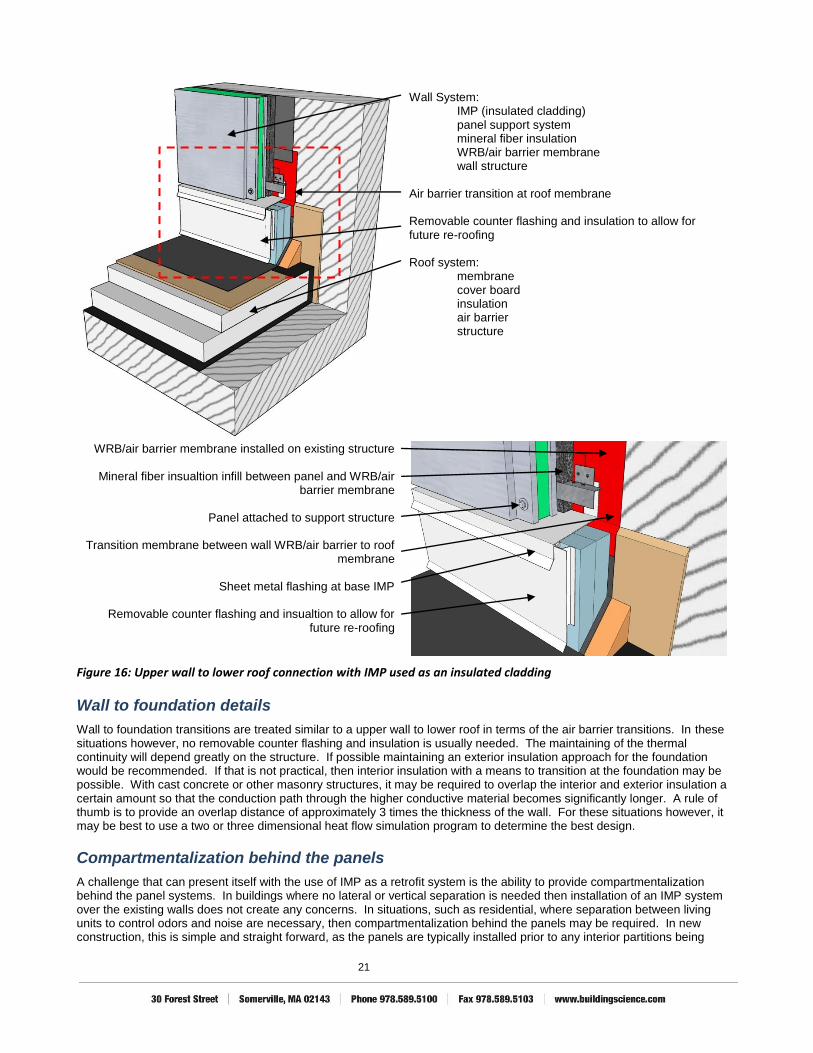
21
Wall System:
IMP (insulated cladding) panel support system mineral fiber insulation WRB/air barrier membrane wall structure
Air barrier transition at roof membrane Removable counter flashing and insulation to allow for future re-roofing Roof system:
membrane cover board insulation air barrier structure
WRB/air barrier membrane installed on existing structure
Mineral fiber insualtion infill between panel and WRB/air barrier membrane
Panel attached to support structure
Transition membrane between wall WRB/air barrier to roof
membrane
Sheet metal flashing at base IMP
Removable counter flashing and insualtion to allow for future re-roofing
Figure 16: Upper wall to lower roof connection with IMP used as an insulated cladding
Wall to foundation details
Wall to foundation transitions are treated similar to a upper wall to lower roof in terms of the air barrier transitions. In these situations however, no removable counter flashing and insulation is usually needed. The maintaining of the thermal continuity will depend greatly on the structure. If possible maintaining an exterior insulation approach for the foundation would be recommended. If that is not practical, then interior insulation with a means to transition at the foundation may be possible. With cast concrete or other masonry structures, it may be required to overlap the interior and exterior insulation a certain amount so that the conduction path through the higher conductive material becomes significantly longer. A rule of thumb is to provide an overlap distance of approximately 3 times the thickness of the wall. For these situations however, it may be best to use a two or three dimensional heat flow simulation program to determine the best design.
Compartmentalization behind the panels
A challenge that can present itself with the use of IMP as a retrofit system is the ability to provide compartmentalization behind the panel systems. In buildings where no lateral or vertical separation is needed then installation of an IMP system over the existing walls does not create any concerns. In situations, such as residential, where separation between living units to control odors and noise are necessary, then compartmentalization behind the panels may be required. In new construction, this is simple and straight forward, as the panels are typically installed prior to any interior partitions being
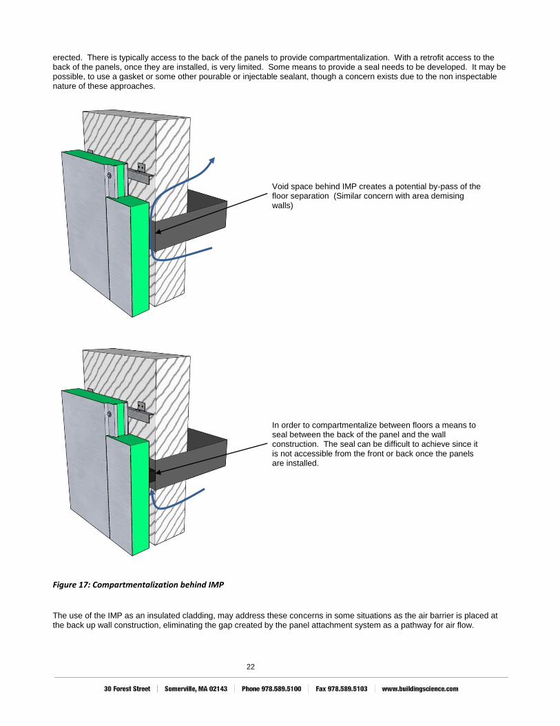
22
erected. There is typically access to the back of the panels to provide compartmentalization. With a retrofit access to the back of the panels, once they are installed, is very limited. Some means to provide a seal needs to be developed. It may be possible, to use a gasket or some other pourable or injectable sealant, though a concern exists due to the non inspectable nature of these approaches.
Void space behind IMP creates a potential by-pass of the floor separation (Similar concern with area demising walls)
In order to compartmentalize between floors a means to seal between the back of the panel and the wall construction. The seal can be difficult to achieve since it is not accessible from the front or back once the panels are installed.
Figure 17: Compartmentalization behind IMP
The use of the IMP as an insulated cladding, may address these concerns in some situations as the air barrier is placed at the back up wall construction, eliminating the gap created by the panel attachment system as a pathway for air flow.

23
Compartmentalization behind the panel is less of a concern when the exterior of the existing wall is an air barrier or is covered with an air barrier.
Figure 18: Compartmentalization through the use of an exterior air barrier membrane
Uneven back up wall construction
With retrofit construction it is common to encounter buildings with exterior walls that are not very even. Wall assemblies may out of plane by several inches or more from top to bottom. When attaching an IMP to the exterior of a building that has very uneven surfaces, it can advantageous to use an adjustable attachment system. A recommended approach is through the use of a clip and angle. The clip fastened to the wall would have a slot opening allowing the placement of the angle to be adjusted inwards or outwards to accommodate variations in the back up wall. For slight variations in the back-up wall, shims or other means to make subtle adjustments may be adequate.
Adjustable connection between the clip and the angle allows for the IMP support system to be adjusted inwards and outwards accommodating variations in the back-up wall.
Figure 19: Adjustable IMP attachment system