Embed Size (px)
Citation preview
Using fractional delay to control the magnitudesand phases of integrators and differentiators
M.A. Al-Alaoui
Abstract: The use of fractional delay to control the magnitudes and phases of integrators and dif-ferentiators has been addressed. Integrators and differentiators are the basic building blocks ofmany systems. Often applications in controls, wave-shaping, oscillators and communicationsrequire a constant 908 phase for differentiators and 2908 phase for integrators. When the designneglects the phase, a phase equaliser is often needed to compensate for the phase error or aphase lock loop should be added. Applications to the first-order, Al-Alaoui integrator and differen-tiator are presented. A fractional delay is added to the integrator leading to an almost constant phaseresponse of 2908. Doubling the sampling rate improves the magnitude response. Combining thetwo actions improves both the magnitude and phase responses. The same approach is applied tothe differentiator, with a fractional sample advance leading to an almost constant phase responseof 908. The advance is, in fact, realised as the ratio of two delays. Filters approximating the frac-tional delay, the finite impulse response (FIR) Lagrange interpolator filters and the Thiran allpassinfinite impulse response (IIR) filters are employed. Additionally, a new hybrid filter, a combi-nation of the FIR Lagrange interpolator filter and the Thiran allpass IIR filter, is proposed.Methods to reduce the approximation error are discussed.
1 Introduction
Rabiner and Steiglitz in [1] noted that introducing a halfsample delay to an ideal differentiator does not change themagnitude response; however, the phase response willbecome linear [2]. The magnitude and phase responses ofthe ideal differentiator are shown in Fig. 1a and b, respect-ively. The Nyquist frequency is normalised to 1, and thesampling frequency is twice the Nyquist frequency. Theideal differentiator has a constant phase response of 908(Fig. 1b). We can clearly see the discontinuity of thephase at the Nyquist frequency. An ideal half sampledelay has a magnitude of unity (Fig. 1c) and a linearphase (Fig. 1d ). Delaying the response of the ideal differen-tiator by a half sample results in a linear phase as shown inFig. 1f. (The magnitude is not affected when the delay isideal as shown by comparing Fig. 1e with Fig. 1a.) Thisprocedure is used in [1] to overcome the problem ofphase discontinuity at the Nyquist frequency.In contrast, Tseng [3] used fractional delay to improve
the magnitude response of the Simpson integrator. Thetransfer function of the Simpson integrator is shown as
HS(z) ¼T
3
(1þ 4z�1þ z�2)
(1� z�2)(1)
He reduced the sampling interval from T to 0.5 T. Reducingthe sampling interval to 0.5 T modifies the transfer function
# The Institution of Engineering and Technology 2007
doi:10.1049/iet-spr:20060246
Paper first received 2nd August 2006 and in revised form 10th March 2007
The author is with the Department of Electrical and Computer Engineering, TheAmerican University of Beirut, Beirut, Lebanon
E-mail: [email protected]
IET Signal Process., 2007, 1, (2), pp. 107–119
of the Simpson integrator to
H0:5S(z) ¼T
6
(1þ 4z�1=2þ z�1)
(1� z�1)(2)
Thus, the relationship between the transfer functions of theSimpson and the modified Simpson integrators may beexpressed as
H0:5S(z) ¼1
2HS(z
1=2) (3)
The problem of how to implement the half sample delay,or for that matter any fractional delay, was developedwith the advances in multirate digital signal processingas implementation of successive interpolation anddecimation and vice versa. Finding efficient designmethods of fractional delay filters is an active researcharea [4–16].
To implement the fractional delay element z21/2, Tsengemployed two of the methods proposed by Laakso et al.[9], the finite impulse response (FIR) fractional delayfilter and the infinite impulse response (IIR) fractionaldelay filter. Thus, a pure integer delay z2N is cascadedwith the modified Simpson integrator as
GN (z) ¼ z�NH0:5S(z)
¼T
6
(z�Nþ 4z�(Nþ(1=2))
þ z�N�1)
(1� z�1)(4)
The problem is reduced to designing the fractional delayelement z2D, where D ¼ Nþ (1/2).
Tseng found that the integrators obtained using theFIR-based design have better performance than thoseobtained using the allpass-based design; thus, only hisresults using the FIR-based design will be reported in
107
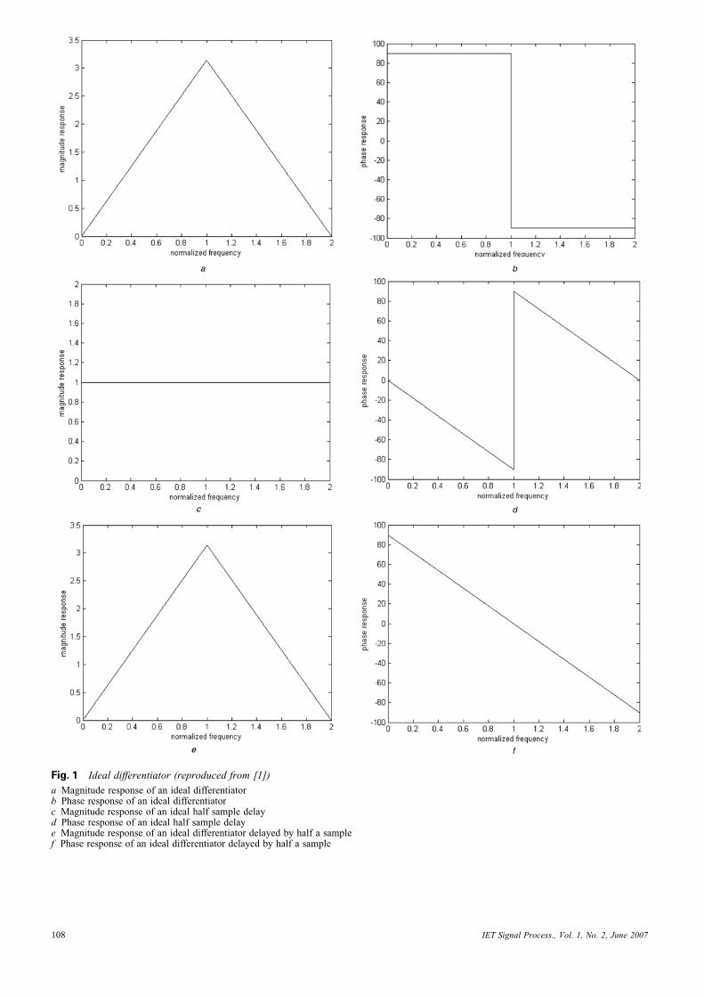
Fig. 1 Ideal differentiator (reproduced from [1])
a Magnitude response of an ideal differentiatorb Phase response of an ideal differentiatorc Magnitude response of an ideal half sample delayd Phase response of an ideal half sample delaye Magnitude response of an ideal differentiator delayed by half a samplef Phase response of an ideal differentiator delayed by half a sample
IET Signal Process., Vol. 1, No. 2, June 2007108
this paper. For the FIR-based design, he reported twocases. In the first case, he chose D ¼ 1/2 and N ¼ 0,which yielded the half sample delay approximationz�1=2 ’ 1=2þ ð1=2Þ z�1. The resulting transfer functionis the same as that of the conventional trapezoidal rule.For the second case, he chose D ¼ 1.5 and N ¼ 1,which yielded the one and a half sample delay
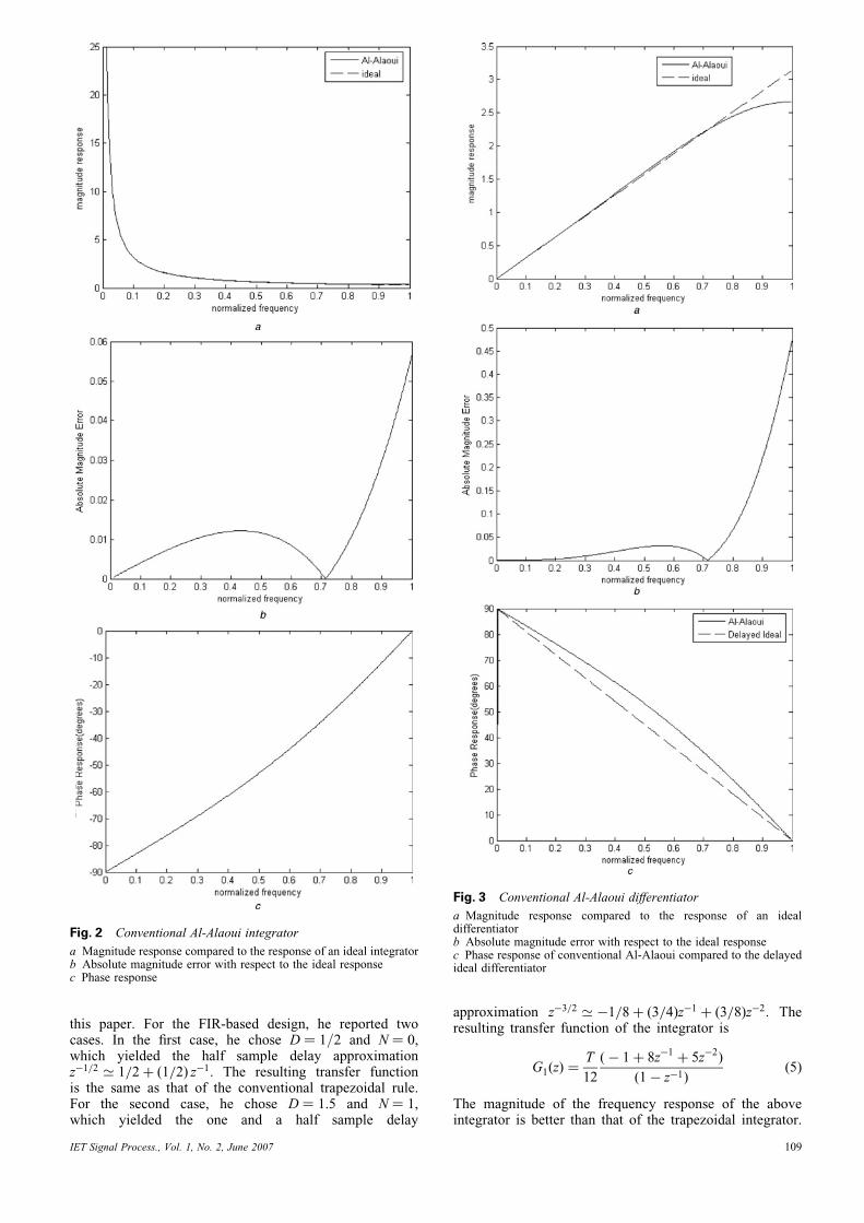
Fig. 2 Conventional Al-Alaoui integrator
a Magnitude response compared to the response of an ideal integratorb Absolute magnitude error with respect to the ideal responsec Phase response
IET Signal Process., Vol. 1, No. 2, June 2007
approximation z�3=2 ’ �1=8þ ð3=4Þz�1 þ ð3=8Þz�2. Theresulting transfer function of the integrator is
G1(z) ¼T
12
(� 1þ 8z�1þ 5z�2)
(1� z�1)(5)
The magnitude of the frequency response of the aboveintegrator is better than that of the trapezoidal integrator.
Fig. 3 Conventional Al-Alaoui differentiator
a Magnitude response compared to the response of an idealdifferentiatorb Absolute magnitude error with respect to the ideal responsec Phase response of conventional Al-Alaoui compared to the delayedideal differentiator
109
However, it introduces an additional sample delay, and itloses the 2908 phase shift.
This paper addresses the use of fractional delay methodsto control the magnitudes and/or phases of integratorsand differentiators with the aim of bringing them to approxi-mate the magnitudes and/or phases of ideal integrators anddifferentiators. Applications to the first-order, Al-Alaouiintegrator and differentiator are presented.
The magnitude and phase responses of the Al-Alaouiintegrator are shown in Fig. 2. The Al-Alaoui integrator isobtained by interpolating the transfer function of the
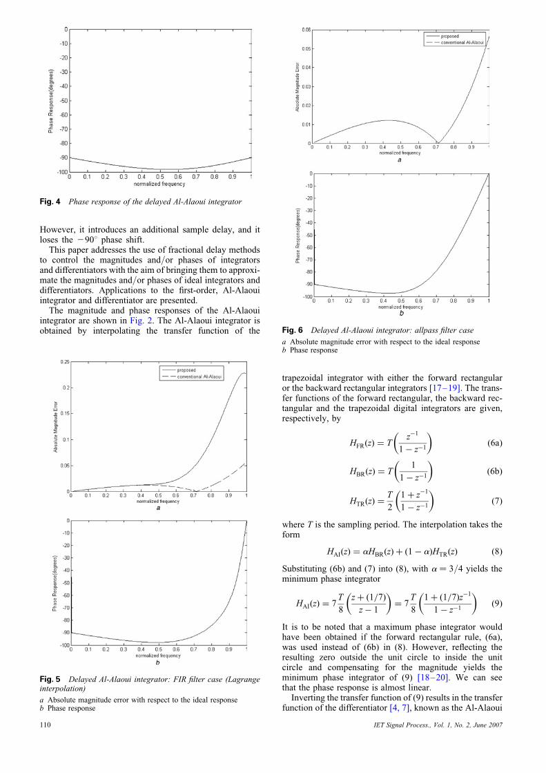
Fig. 4 Phase response of the delayed Al-Alaoui integrator
Fig. 5 Delayed Al-Alaoui integrator: FIR filter case (Lagrangeinterpolation)
a Absolute magnitude error with respect to the ideal responseb Phase response
110
trapezoidal integrator with either the forward rectangularor the backward rectangular integrators [17–19]. The trans-fer functions of the forward rectangular, the backward rec-tangular and the trapezoidal digital integrators are given,respectively, by
HFR(z) ¼ Tz�1
1� z�1
� �(6a)
HBR(z) ¼ T1
1� z�1
� �(6b)
HTR(z) ¼T
2
1þ z�1
1� z�1
� �(7)
where T is the sampling period. The interpolation takes theform
HAI(z) ¼ aHBR(z)þ (1� a)HTR(z) (8)
Substituting (6b) and (7) into (8), with a ¼ 3/4 yields theminimum phase integrator
HAI(z) ¼ 7T
8
zþ (1=7)
z� 1
� �¼ 7
T
8
1þ (1=7)z�1
1� z�1
� �(9)
It is to be noted that a maximum phase integrator wouldhave been obtained if the forward rectangular rule, (6a),was used instead of (6b) in (8). However, reflecting theresulting zero outside the unit circle to inside the unitcircle and compensating for the magnitude yields theminimum phase integrator of (9) [18–20]. We can seethat the phase response is almost linear.Inverting the transfer function of (9) results in the transfer
function of the differentiator [4, 7], known as the Al-Alaoui
Fig. 6 Delayed Al-Alaoui integrator: allpass filter case
a Absolute magnitude error with respect to the ideal responseb Phase response
IET Signal Process., Vol. 1, No. 2, June 2007
operator [20, 21], and is given as
HAD(z) ¼8(z� 1)
7T (zþ (1=7))¼
8(1� z�1)
7T (1þ (1=7)z�1)(10)
The resulting differentiator is stable, with a pole atz ¼ 21/7, and has an almost linear phase as shown inFig. 3c.A fractional delay is added to the integrator leading to an
almost constant phase response of 2908.We would like to reach an almost constant 908 phase for
the Al-Alaoui differentiator. Hence, the reverse of theprocess mentioned previously for linearising the phase ofthe ideal differentiator is applied: introducing a halfsample advance to the Al-Alaoui differentiator will leadto an almost constant 908 phase response.It should be noted that the approach applies to other dif-
ferentiators and integrators with linear phases, or approxi-mately linear phases, such as the second-order Al-Alaouiintegrators and differentiators [22–24]. In fact, it wasapplied in [3] to the Simpson integrator, which becomesone of the second-order Al-Alaoui differentiators when itstransfer function is inverted. However, this paper will delin-eate only the first-order Al-Alaoui integrators and differen-tiators and, for brevity, the term ‘first-order’ will besuppressed.
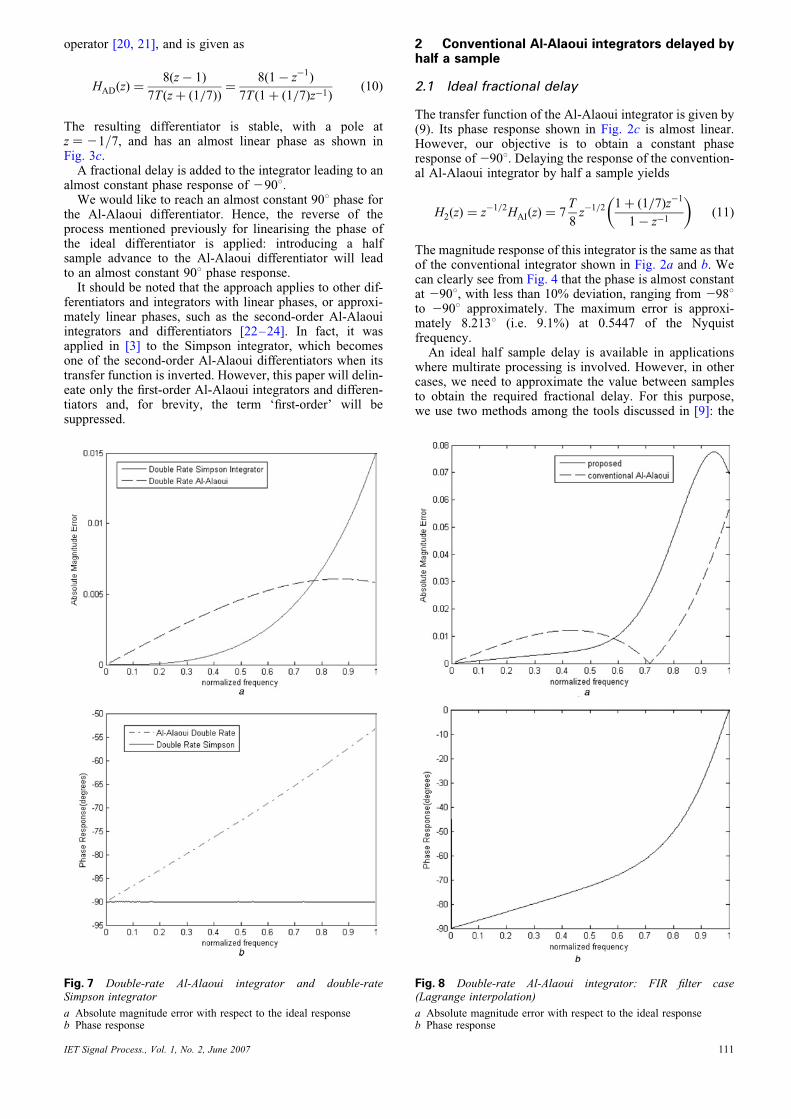
Fig. 7 Double-rate Al-Alaoui integrator and double-rateSimpson integrator
a Absolute magnitude error with respect to the ideal responseb Phase response
IET Signal Process., Vol. 1, No. 2, June 2007
2 Conventional Al-Alaoui integrators delayed byhalf a sample
2.1 Ideal fractional delay
The transfer function of the Al-Alaoui integrator is given by(9). Its phase response shown in Fig. 2c is almost linear.However, our objective is to obtain a constant phaseresponse of2908. Delaying the response of the convention-al Al-Alaoui integrator by half a sample yields
H2(z) ¼ z�1=2
HAI(z) ¼ 7T
8z�1=2 1þ (1=7)z�1
1� z�1
� �(11)
The magnitude response of this integrator is the same as thatof the conventional integrator shown in Fig. 2a and b. Wecan clearly see from Fig. 4 that the phase is almost constantat 2908, with less than 10% deviation, ranging from 2988to 2908 approximately. The maximum error is approxi-mately 8.2138 (i.e. 9.1%) at 0.5447 of the Nyquistfrequency.
An ideal half sample delay is available in applicationswhere multirate processing is involved. However, in othercases, we need to approximate the value between samplesto obtain the required fractional delay. For this purpose,we use two methods among the tools discussed in [9]: the
Fig. 8 Double-rate Al-Alaoui integrator: FIR filter case(Lagrange interpolation)
a Absolute magnitude error with respect to the ideal responseb Phase response
111
FIR case (Lagrange interpolation) and the allpass filter case.These methods are attractive because the delay filter coeffi-cients are obtained in closed form.
2.2 Fractional delay approximated by an FIR filter(Lagrange interpolation)
With this approximation, a total delay D is approximated by[3, 9]
z�D ’
XLn¼0
h(n)z�n, h(n) ¼YL
k¼0,k=n
D� k
n� k(12)
The filter-order L is chosen such that (L� 1)=2 �
D � (Lþ 1)=2.Moreover, the total delay D is expressed as D ¼ Nþ d,
where N is the integer part of the delay and d the fractionalpart. The integer part of the delay is needed to increase thefilter order to obtain a better approximation of the fractionaldelay. However, this will affect the phase response and therequired 2908 phase will not be obtained. To solve thisproblem and delay the response only by the fractional partd, we multiply the integrator’s transfer functionby z�N�d=z�N instead of z�N�d , where z�N�d is approxi-mated by the FIR filter in (12).
The magnitude and frequency responses of the delayedAl-Alaoui integrator, with the delay approximated by
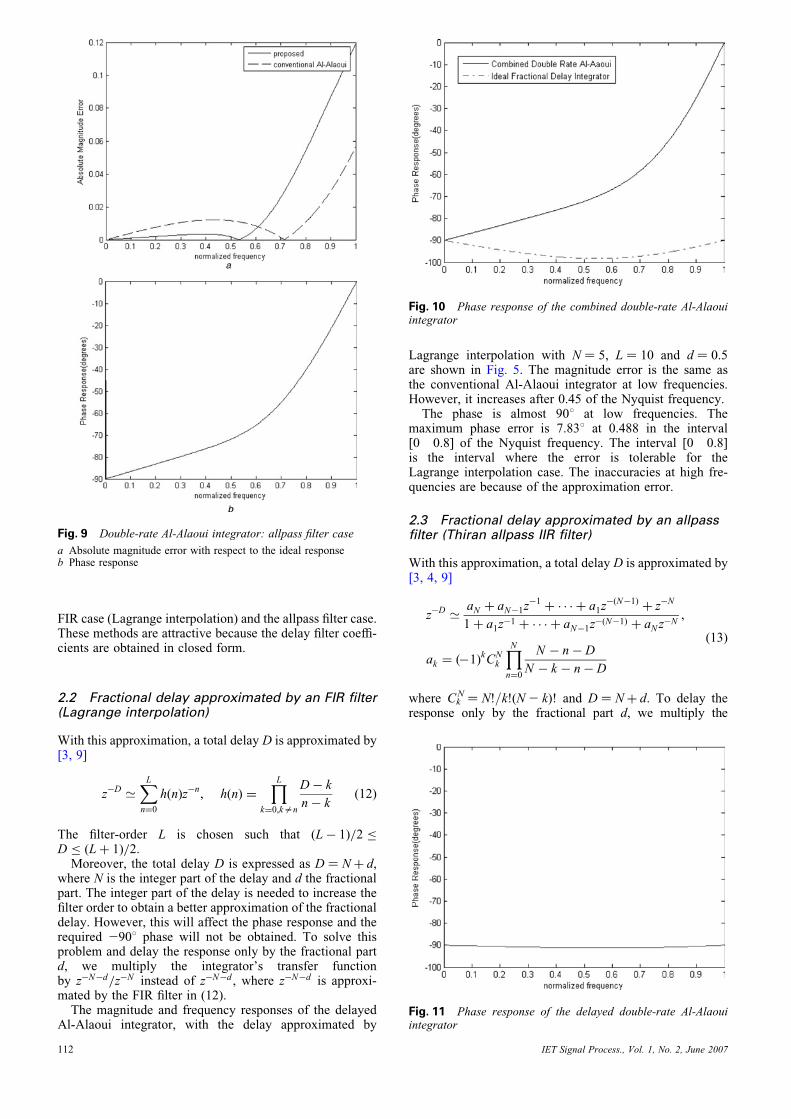
Fig. 9 Double-rate Al-Alaoui integrator: allpass filter case
a Absolute magnitude error with respect to the ideal responseb Phase response
112
Lagrange interpolation with N ¼ 5, L ¼ 10 and d ¼ 0.5are shown in Fig. 5. The magnitude error is the same asthe conventional Al-Alaoui integrator at low frequencies.However, it increases after 0.45 of the Nyquist frequency.The phase is almost 908 at low frequencies. The
maximum phase error is 7.838 at 0.488 in the interval[0 0.8] of the Nyquist frequency. The interval [0 0.8]is the interval where the error is tolerable for theLagrange interpolation case. The inaccuracies at high fre-quencies are because of the approximation error.
2.3 Fractional delay approximated by an allpassfilter (Thiran allpass IIR filter)
With this approximation, a total delay D is approximated by[3, 4, 9]
z�D ’ aN þ aN�1z�1
þ � � � þ a1z�(N�1)
þ z�N
1þ a1z�1 þ � � � þ aN�1z
�(N�1) þ aNz�N
,
ak ¼ (�1)kCNk
YNn¼0
N � n� D
N � k � n� D
(13)
where CkN ¼ N!/k!(N2 k)! and D ¼ Nþ d. To delay the
response only by the fractional part d, we multiply the
Fig. 10 Phase response of the combined double-rate Al-Alaouiintegrator
Fig. 11 Phase response of the delayed double-rate Al-Alaouiintegrator
IET Signal Process., Vol. 1, No. 2, June 2007
integrator’s transfer function by z2N 2d/z2N instead ofz2N 2d, where z2N 2d is approximated by the allpass filterin (13). The frequency responses of the delayed Al-Alaouiintegrator, with the delay approximated by the Thiranallpass IIR filter with N ¼ 5 and d ¼ 0.5 are shown in Fig. 6.The magnitude error is the same as the conventional
Al-Alaoui. Hence, using the allpass filter approximation toenhance the phase response did not entail any penalty onthe magnitude response. The phase is almost 908 at low fre-quencies. The maximum phase error is 7.278 at 0.43 in theinterval [0 0.675] of the Nyquist frequency. The interval[0 0.675] is the interval where the error is tolerable forthe allpass filter case. The inaccuracies at high frequenciesare, again, because of the approximation error.
3 Double-rate Al-Alaoui integrator
3.1 Ideal fractional delay
Using a sampling period of T/2 (i.e. doubling the samplingrate), (9) becomes
H3(z) ¼ 7(T=2)
8
1þ (1=7)z�1=2
1� z�1=2
� �
¼ 7T
16
� �1þ (1=7)z�1=2
1� z�1=2
� �(14)
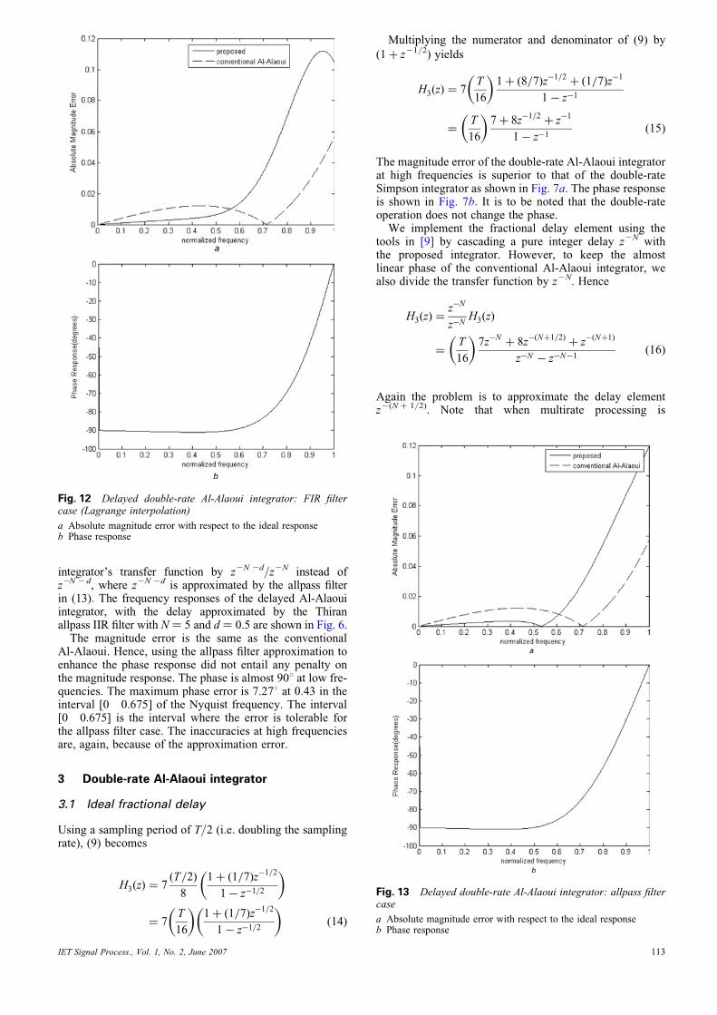
Fig. 12 Delayed double-rate Al-Alaoui integrator: FIR filtercase (Lagrange interpolation)
a Absolute magnitude error with respect to the ideal responseb Phase response
IET Signal Process., Vol. 1, No. 2, June 2007
Multiplying the numerator and denominator of (9) by
(1þ z21/2) yields
H3(z) ¼ 7T
16
� �1þ (8=7)z�1=2
þ (1=7)z�1
1� z�1
¼T
16
� �7þ 8z�1=2
þ z�1
1� z�1(15)
The magnitude error of the double-rate Al-Alaoui integratorat high frequencies is superior to that of the double-rateSimpson integrator as shown in Fig. 7a. The phase responseis shown in Fig. 7b. It is to be noted that the double-rateoperation does not change the phase.
We implement the fractional delay element using thetools in [9] by cascading a pure integer delay z2N withthe proposed integrator. However, to keep the almostlinear phase of the conventional Al-Alaoui integrator, wealso divide the transfer function by z2N. Hence
H3(z) ¼z�N
z�NH3(z)
¼T
16
� �7z�N
þ 8z�(Nþ1=2)þ z
�(Nþ1)
z�N � z�N�1(16)
Again the problem is to approximate the delay elementz2(N þ 1/2). Note that when multirate processing is
Fig. 13 Delayed double-rate Al-Alaoui integrator: allpass filtercase
a Absolute magnitude error with respect to the ideal responseb Phase response
113
available, the values half way between the samples arealready available and there is no need for approximationor use of z2N. (The values of Fig. 7 are then realisable inpractice.) We use the two methods we employed inSection 2: The FIR filter method using Lagrange interp-olation and the allpass filter method.
3.2 Double-rate Al-Alaoui integrator withfractional delay approximated by an FIR filter(Lagrange interpolation)
We implement (16) using the fractional delay approxi-mation of (12). The results are shown in Fig. 8. By compar-ing Fig. 8a with Fig. 2b, we see that the magnitude error atlow frequencies is lower for the FIR case. However, itincreases slightly above that of the conventionalAl-Alaoui integrator at high frequencies. The phaseresponse is linear in the low-frequency range (Fig. 8b)similar to Fig. 7b, but linearity is lost at high frequenciesbecause of the approximation filter error.
3.3 Double-rate Al-Alaoui integrator withfractional delay approximated by an allpass filter
We implement (16) using the fractional delay approxi-mation of (13). The results are shown in Fig. 9. By
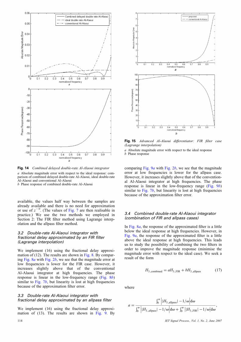
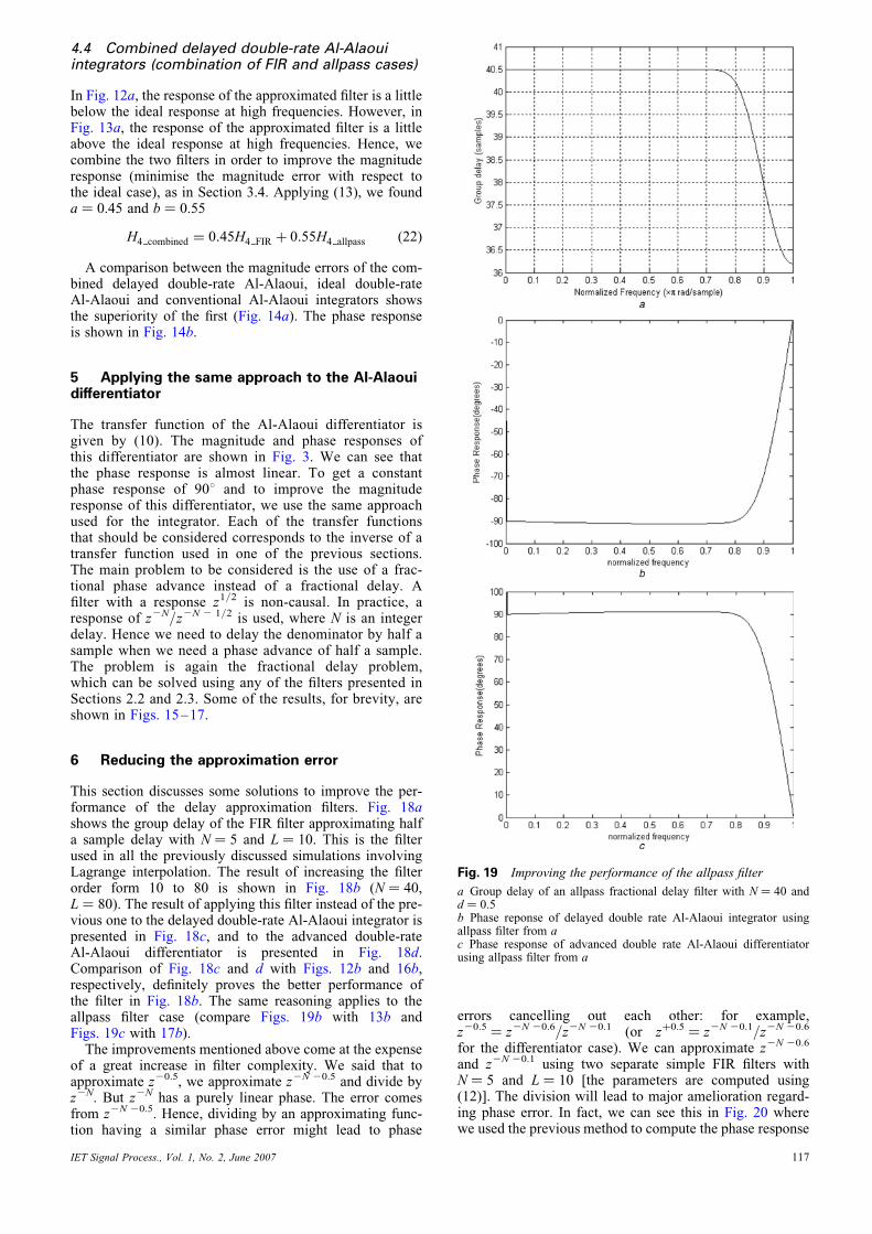
Fig. 14 Combined delayed double-rate Al-Alaoui integrator
a Absolute magnitude error with respect to the ideal response: com-parison of combined delayed double-rate Al-Alaoui, ideal double-rateAl-Alaoui and conventional Al-Alaouib Phase response of combined double-rate Al-Alaoui
114
comparing Fig. 9a with Fig. 2b, we see that the magnitudeerror at low frequencies is lower for the allpass case.However, it increases slightly above that of the convention-al Al-Alaoui integrator at high frequencies. The phaseresponse is linear in the low-frequency range (Fig. 9b)similar to Fig. 7b, but linearity is lost at high frequenciesbecause of the approximation filter error.
3.4 Combined double-rate Al-Alaoui integrator(combination of FIR and allpass cases)
In Fig. 8a, the response of the approximated filter is a littlebelow the ideal response at high frequencies. However, inFig. 9a, the response of the approximated filter is a littleabove the ideal response at high frequencies. This leadsus to study the possibility of combining the two filters inorder to improve the magnitude response (minimise themagnitude error with respect to the ideal case). We seek aresult of the form
H3 combined ¼ aH3 FIR þ bH3 allpass (17)
where
a ¼
Ð p0
jH3 allpassj �1=v��� ���dv
Ð p0
jH3 allpassj �1=v��� ���dvþ
Ð p0
jH3 FIRj �1=v�� ��dv ,
Fig. 15 Advanced Al-Alaoui differentiator: FIR filter case(Lagrange interpolation)
a Absolute magnitude error with respect to the ideal responseb Phase response
IET Signal Process., Vol. 1, No. 2, June 2007
b ¼
Ð p0
jHFIRj �1=v�� ��dvРp
0jH3 allpassj �1=v��� ���dvþ
Ð p0
jH3 FIRj �1=v�� ��dv
(18)
We found a ¼ 0.55 and b ¼ 0.45. Hence, we define
H3 combined ¼ 0:55H3 FIR þ 0:45H3 allpass (19)
The magnitude errors of the combined double-rateAl-Alaoui integrator is almost identical to that of the idealdouble-rate Al-Alaoui integrator (Fig. 7a), and is omittedfor brevity. The phase response is shown in Fig. 10.
4 Double-rate Al-Alaoui integrator delayed by0.2 samples
4.1 Ideal fractional delay
In Section 2, we tried to enhance the phase response of theAl-Alaoui integrator to obtain a constant phase of 2908. InSection 3, we doubled the sampling rate to improve themagnitude response of the integrator. Now, we would liketo combine the results to improve both the magnitude andphase responses at the same time. We want the double-rateAl-Alaoui integrator to yield a constant phase responseof 2908.
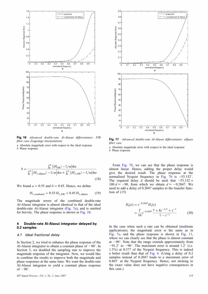
Fig. 16 Advanced double-rate Al-Alaoui differentiator: FIRfilter case (Lagrange interpolation)
a Absolute magnitude error with respect to the ideal responseb Phase response
IET Signal Process., Vol. 1, No. 2, June 2007
From Fig. 7b, we can see that the phase response isalmost linear. Hence, adding the proper delay wouldgive the desired result. The phase response at thenormalised Nyquist frequency in Fig. 7b is 253.1528.The required delay d should be such that 253.152þ180 d ¼ 290, from which we obtain d ¼ 20.2047. Weneed to add a delay of 0.2047 samples to the transfer func-tion of (15)
H4(z) ¼ z�0:2047H3(z)
¼T
16z�0:2047 7þ 8z�1=2
þ z�1
1� z�1(20)
In the case when such a rate can be obtained (multirateapplications), the magnitude error is the same as inFig. 7a, and the phase response is shown in Fig. 11,where we can clearly see that the phase is almost constantat 2908. Note that the range extends approximately from291.28 to 2908. The maximum error is around 1.28 (i.e.1.3%) at 0.577 of the Nyquist frequency. This is indeeda better result than that of Fig. 4. (Using a delay of 0.2samples instead of 0.2047 leads to a maximum error of0.8658 at the Nyquist frequency. Hence, not sticking tothe exact value does not have negative consequences inthis case.)
Fig. 17 Advanced double-rate Al-Alaoui differentiator: allpassfilter case
a Absolute magnitude error with respect to the ideal responseb Phase response
115
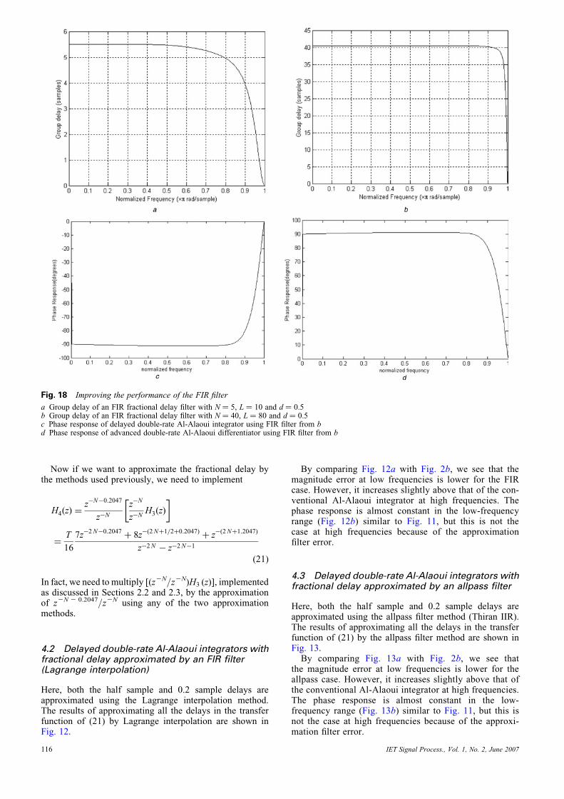
Fig. 18 Improving the performance of the FIR filter
a Group delay of an FIR fractional delay filter with N ¼ 5, L ¼ 10 and d ¼ 0.5b Group delay of an FIR fractional delay filter with N ¼ 40, L ¼ 80 and d ¼ 0.5c Phase response of delayed double-rate Al-Alaoui integrator using FIR filter from bd Phase response of advanced double-rate Al-Alaoui differentiator using FIR filter from b
Now if we want to approximate the fractional delay bythe methods used previously, we need to implement
H4(z) ¼z�N�0:2047
z�N
z�N
z�NH3(z)
� �
¼T
16
7z�2N�0:2047þ 8z�(2Nþ1=2þ0:2047)
þ z�(2Nþ1:2047)
z�2N � z�2N�1
(21)
In fact, we need to multiply [(z2N/z2N)H3 (z)], implementedas discussed in Sections 2.2 and 2.3, by the approximationof z2N 2 0.2047/z2N using any of the two approximationmethods.
4.2 Delayed double-rate Al-Alaoui integrators withfractional delay approximated by an FIR filter(Lagrange interpolation)
Here, both the half sample and 0.2 sample delays areapproximated using the Lagrange interpolation method.The results of approximating all the delays in the transferfunction of (21) by Lagrange interpolation are shown inFig. 12.
116
By comparing Fig. 12a with Fig. 2b, we see that themagnitude error at low frequencies is lower for the FIRcase. However, it increases slightly above that of the con-ventional Al-Alaoui integrator at high frequencies. Thephase response is almost constant in the low-frequencyrange (Fig. 12b) similar to Fig. 11, but this is not thecase at high frequencies because of the approximationfilter error.
4.3 Delayed double-rate Al-Alaoui integrators withfractional delay approximated by an allpass filter
Here, both the half sample and 0.2 sample delays areapproximated using the allpass filter method (Thiran IIR).The results of approximating all the delays in the transferfunction of (21) by the allpass filter method are shown inFig. 13.By comparing Fig. 13a with Fig. 2b, we see that
the magnitude error at low frequencies is lower for theallpass case. However, it increases slightly above that ofthe conventional Al-Alaoui integrator at high frequencies.The phase response is almost constant in the low-frequency range (Fig. 13b) similar to Fig. 11, but this isnot the case at high frequencies because of the approxi-mation filter error.
IET Signal Process., Vol. 1, No. 2, June 2007
4.4 Combined delayed double-rate Al-Alaouiintegrators (combination of FIR and allpass cases)
In Fig. 12a, the response of the approximated filter is a littlebelow the ideal response at high frequencies. However, inFig. 13a, the response of the approximated filter is a littleabove the ideal response at high frequencies. Hence, wecombine the two filters in order to improve the magnituderesponse (minimise the magnitude error with respect tothe ideal case), as in Section 3.4. Applying (13), we founda ¼ 0.45 and b ¼ 0.55
H4 combined ¼ 0:45H4 FIR þ 0:55H4 allpass (22)
A comparison between the magnitude errors of the com-bined delayed double-rate Al-Alaoui, ideal double-rateAl-Alaoui and conventional Al-Alaoui integrators showsthe superiority of the first (Fig. 14a). The phase responseis shown in Fig. 14b.
5 Applying the same approach to the Al-Alaouidifferentiator
The transfer function of the Al-Alaoui differentiator isgiven by (10). The magnitude and phase responses ofthis differentiator are shown in Fig. 3. We can see thatthe phase response is almost linear. To get a constantphase response of 908 and to improve the magnituderesponse of this differentiator, we use the same approachused for the integrator. Each of the transfer functionsthat should be considered corresponds to the inverse of atransfer function used in one of the previous sections.The main problem to be considered is the use of a frac-tional phase advance instead of a fractional delay. Afilter with a response z1/2 is non-causal. In practice, aresponse of z2N/z2N 2 1/2 is used, where N is an integerdelay. Hence we need to delay the denominator by half asample when we need a phase advance of half a sample.The problem is again the fractional delay problem,which can be solved using any of the filters presented inSections 2.2 and 2.3. Some of the results, for brevity, areshown in Figs. 15–17.
6 Reducing the approximation error
This section discusses some solutions to improve the per-formance of the delay approximation filters. Fig. 18ashows the group delay of the FIR filter approximating halfa sample delay with N ¼ 5 and L ¼ 10. This is the filterused in all the previously discussed simulations involvingLagrange interpolation. The result of increasing the filterorder form 10 to 80 is shown in Fig. 18b (N ¼ 40,L ¼ 80). The result of applying this filter instead of the pre-vious one to the delayed double-rate Al-Alaoui integrator ispresented in Fig. 18c, and to the advanced double-rateAl-Alaoui differentiator is presented in Fig. 18d.Comparison of Fig. 18c and d with Figs. 12b and 16b,respectively, definitely proves the better performance ofthe filter in Fig. 18b. The same reasoning applies to theallpass filter case (compare Figs. 19b with 13b andFigs. 19c with 17b).The improvements mentioned above come at the expense
of a great increase in filter complexity. We said that toapproximate z20.5, we approximate z2N 20.5 and divide byz2N. But z2N has a purely linear phase. The error comesfrom z2N 20.5. Hence, dividing by an approximating func-tion having a similar phase error might lead to phase
IET Signal Process., Vol. 1, No. 2, June 2007
errors cancelling out each other: for example,z20.5 ¼ z2N 20.6/z2N 20.1 (or zþ0.5 ¼ z2N 20.1/z2N 20.6
for the differentiator case). We can approximate z2N 20.6
and z2N 20.1 using two separate simple FIR filters withN ¼ 5 and L ¼ 10 [the parameters are computed using(12)]. The division will lead to major amelioration regard-ing phase error. In fact, we can see this in Fig. 20 wherewe used the previous method to compute the phase response
Fig. 19 Improving the performance of the allpass filter
a Group delay of an allpass fractional delay filter with N ¼ 40 andd ¼ 0.5b Phase reponse of delayed double rate Al-Alaoui integrator usingallpass filter from ac Phase response of advanced double rate Al-Alaoui differentiatorusing allpass filter from a
117
of the delayed conventional Al-Alaoui integrator. Using themethod to compute the phase response of the advanced con-ventional Al-Alaoui differentiator (the FIR filter usedapproximates zþ0.5 by approximating the ratio z2N 20.1/z2N 20.6) yields a phase response which is simply minusthe phase response of the integrator and the corresponding
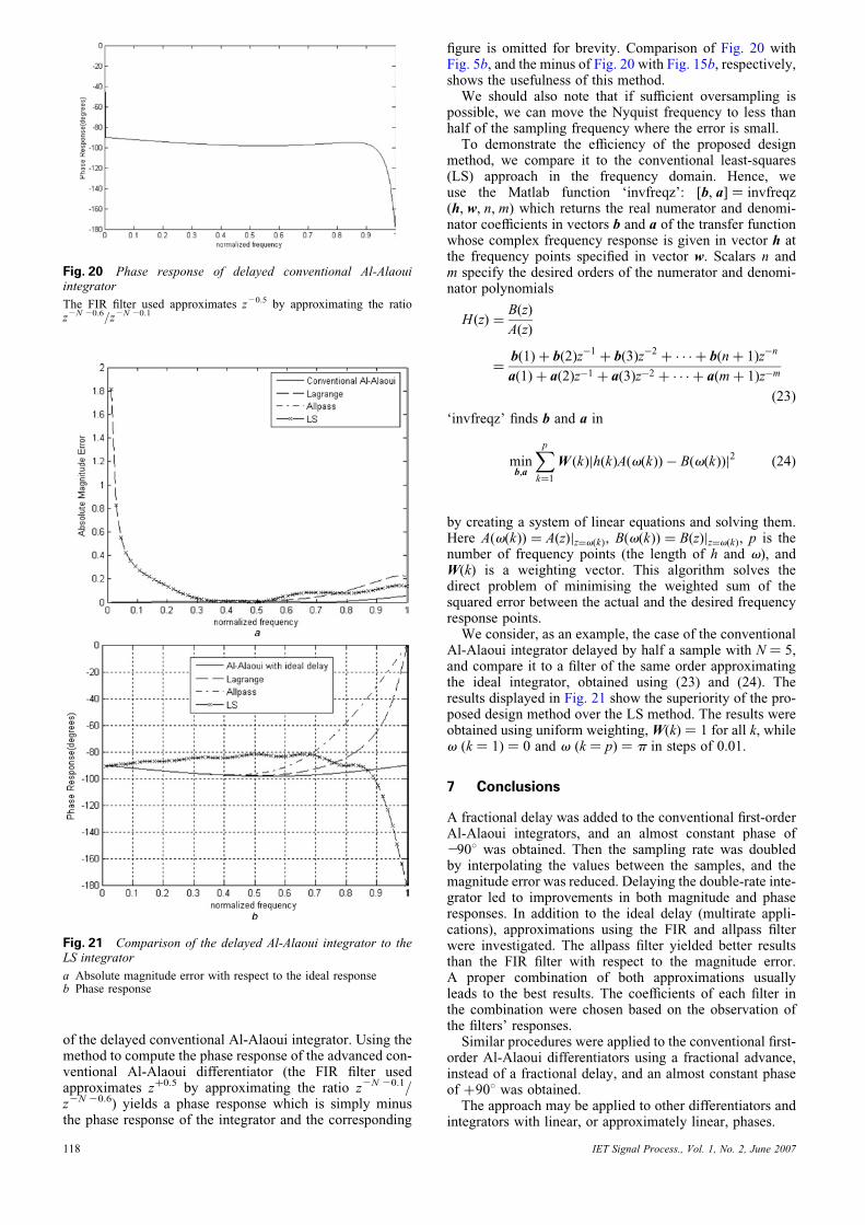
Fig. 21 Comparison of the delayed Al-Alaoui integrator to theLS integrator
a Absolute magnitude error with respect to the ideal responseb Phase response
Fig. 20 Phase response of delayed conventional Al-Alaouiintegrator
The FIR filter used approximates z20.5 by approximating the ratioz2N 20.6/z2N 20.1
118
figure is omitted for brevity. Comparison of Fig. 20 withFig. 5b, and the minus of Fig. 20 with Fig. 15b, respectively,shows the usefulness of this method.We should also note that if sufficient oversampling is
possible, we can move the Nyquist frequency to less thanhalf of the sampling frequency where the error is small.To demonstrate the efficiency of the proposed design
method, we compare it to the conventional least-squares(LS) approach in the frequency domain. Hence, weuse the Matlab function ‘invfreqz’: [b, a] ¼ invfreqz(h, w, n, m) which returns the real numerator and denomi-nator coefficients in vectors b and a of the transfer functionwhose complex frequency response is given in vector h atthe frequency points specified in vector w. Scalars n andm specify the desired orders of the numerator and denomi-nator polynomials
H(z) ¼B(z)
A(z)
¼b(1)þ b(2)z�1
þ b(3)z�2þ � � � þ b(nþ 1)z�n
a(1)þ a(2)z�1 þ a(3)z�2 þ � � � þ a(mþ 1)z�m
(23)
‘invfreqz’ finds b and a in
minb,a
Xpk¼1
W (k)jh(k)A(v(k))� B(v(k))j2 (24)
by creating a system of linear equations and solving them.Here A(v(k)) ¼ A(z)jz¼v(k), B(v(k)) ¼ B(z)jz¼v(k), p is thenumber of frequency points (the length of h and v), andW(k) is a weighting vector. This algorithm solves thedirect problem of minimising the weighted sum of thesquared error between the actual and the desired frequencyresponse points.We consider, as an example, the case of the conventional
Al-Alaoui integrator delayed by half a sample with N ¼ 5,and compare it to a filter of the same order approximatingthe ideal integrator, obtained using (23) and (24). Theresults displayed in Fig. 21 show the superiority of the pro-posed design method over the LS method. The results wereobtained using uniform weighting,W(k) ¼ 1 for all k, whilev (k ¼ 1) ¼ 0 and v (k ¼ p) ¼ p in steps of 0.01.
7 Conclusions
A fractional delay was added to the conventional first-orderAl-Alaoui integrators, and an almost constant phase of2908 was obtained. Then the sampling rate was doubledby interpolating the values between the samples, and themagnitude error was reduced. Delaying the double-rate inte-grator led to improvements in both magnitude and phaseresponses. In addition to the ideal delay (multirate appli-cations), approximations using the FIR and allpass filterwere investigated. The allpass filter yielded better resultsthan the FIR filter with respect to the magnitude error.A proper combination of both approximations usuallyleads to the best results. The coefficients of each filter inthe combination were chosen based on the observation ofthe filters’ responses.Similar procedures were applied to the conventional first-
order Al-Alaoui differentiators using a fractional advance,instead of a fractional delay, and an almost constant phaseof þ908 was obtained.The approach may be applied to other differentiators and
integrators with linear, or approximately linear, phases.
IET Signal Process., Vol. 1, No. 2, June 2007
8 Acknowledgments
It is indeed a pleasure to acknowledge E. Yaacoub, G. Deeb,K. Joujou and I. Al-Kamal for their invaluable help in theproduction of this work. Thanks are also due to theoutstanding reviewers and the Editor-in-Chief whoseconstructive comments contributed considerably to theimprovement of the paper. This research was supported,in part, by the University Research Board of theAmerican University of Beirut.
9 References
1 Rabiner, L.R., and Steiglitz, K.: ‘The design of wide-band recursiveand nonrecursive digital differentiators’, IEEE Trans. AudioElectroacoust., 1970, 18, (2), pp. 204–209
2 Oppenheim, A.V., Wilsky, A.S., and Nawab, S.H.: ‘Signals andsystems’ (Prentice-Hall, Englewood Cliffs, NJ, 1997, 2nd edn.)
3 Tseng, C.C.: ‘Digital integrator design using Simpson rule andfractional delay filter’, IEE Proc., Vis. Image Signal Process., 2006,153, (1), pp. 79–85
4 Thiran, J.-P.: ‘Recursive digital filters with maximally flat groupdelay’, IEEE Trans. Circuit Theory, 1971, CT-18, pp. 659–664
5 Crochiere, R.E., and Rabiner, L.R.: ‘Multirate digital signalprocessing’ (Prentice-Hall, Englewood Cliffs, NJ, 1983)
6 Minocha, S., Dutta Roy, S.C., and Kumar, B.: ‘A note on the FIRapproximation of a fractional sample delay’, Int. J. Circuit TheoryAppl., 1993, 21, (3), pp. 265–274
7 Vaidyanathan, P.P.: ‘Multi rate systems and filter banks’(Prentice-Hall, Englewood Cliffs, NJ, 1993)
8 Fliege, N.J.: ‘Multirate digital signal processing’ (Wiley, New York,1994)
9 Laakso, T.I., Valimaki, V., Karjalainen, M., and Laine, U.K.:‘Splitting the unit delay: tools for fractional delay filter design’,IEEE Signal Process., Mag., 1996, 13, (1), pp. 30–60
10 Tassart, S., and Depalle, P.: ‘Analytical approximations of fractionaldelays: Lagrange interpolators and allpass filters’. Proc. ICASSP-97,Munich, Germany, April 1997, vol. 1, pp. 455–458
IET Signal Process., Vol. 1, No. 2, June 2007
11 Luengo, D., Pantaleon, C.J., and Santamaria, I.: ‘Design ofsimultaneous sampling systems based on fractional delayLagrange filters’, IEEE Trans. Circuits Syst. II, 2000, 47, (5),pp. 482–485
12 Valimaki, V., and Laakso, T.I.: ‘Principles of fractional delayfilters’. IEEE ICASSP’00, Istanbul, Turkey, June 2000, vol. 6,pp. 3870–3873
13 Pei, S.-C., and Wang, P.-H.: ‘Closed-form design of maximally flatFIR Hilbert transformers, differentiators, and fractional delayers bypower series expansion’, IEEE Trans. Circuits Syst. I, 2001, 48, (4),pp. 389–398
14 Nagahara, M., and Yamamoto, Y.: ‘Optimal design of fractional delayfilters’. Proc. 42nd IEEE Conf. Decision and Control, Maui, Hawaii,December 2003, pp. 6539–6544
15 Pei, S.-C., and Wang, P.-H.: ‘Closed-form design of all-passfractional delay filters’, IEEE Signal Process. Lett., 2004, 11, (10),pp. 788–791
16 Mitra, S.K.: ‘Digital signal processing’ (McGraw-Hill, New York,2006, 3rd edn.)
17 Al-Alaoui, M.A.: ‘Novel digital integrator and differentiator’,Electron. Lett., 1993, 29, pp. 376–378 [see also Errata, Electron.Lett., 1993, 29, (10), p. 934]
18 Al-Alaoui, M.A.: ‘Filling the gap between the bilinear and thebackward difference transforms: an interactive design approach’,Int. J. Elec. Eng. Educ., 1997, 34, (4), pp. 331–337
19 Al-Alaoui, M.A.: ‘Al-Alaoui operator and the a-approximation fordiscretization of analog systems’, Facta Univ. Ser. Elec. Energ.,2006, 19, (1), pp. 143–146
20 Al-Alaoui, M.A.: ‘Novel approach to designing digitaldifferentiators’, Electron. Lett., 1992, 28, (15), pp. 1376–1378
21 Chen, Y.Q., and Moore, K.L.: ‘Discretization schemes for fractionalorder differentiators and integrators’, IEEE Trans. Circuits Syst. I,2002, 49, (3), pp. 363–367
22 Al-Alaoui, M.A.: ‘A class of second order integrators and lowpassdifferentiators’, IEEE Trans. Circuits Syst. I, 1995, 42, (4),pp. 220–223
23 Al-Alaoui, M.A.: ‘Novel IIR differentiator from the Simpsonintegration rule’, IEEE Trans. Circuits Syst. I, 1994, 41, (2),pp. 186–187
24 Al-Alaoui, M.A.: ‘Novel stable higher order s-to-z transforms’, IEEETrans. Circuits Syst. I, 2001, 48, (11), pp. 1326–1329
119


![Oscillation criteria for a class of fractional delay differential equations... · 2018. 10. 31. · ZhuandXiangAdvancesinDifferenceEquations20182018:403 Page2of11 Laplacetransformmethodin[16];thestabilityandasymptoticpropertiesofFDDEswere](https://img.pdfslide.us/doc/110x75/60f2517411c6b73fea0293f4/oscillation-criteria-for-a-class-of-fractional-delay-differential-equations-.jpg)