Embed Size (px)
Citation preview

2500 Series® Programmable Automation Control System
Application Note
Using the 2500P-ACP1 Application Coprocessor for Ethernet/IP Communications
Ethernet/IP is a member of a family of networks that implement the Common Industrial Protocol (CIP). CIP encompasses a comprehensive suite of messages and services that facilitate a variety of manufacturing automation applications, including control, motion, and data access. Ethernet/IP employs standard Ethernet and TCP/IP technologies, allowing commonly available components, protocol stacks, and diagnostic tools to be used.
COMMON INDUSTRIAL PROTOCOL (CIP)
CIP is an object oriented protocol, where every node is represented by a collection of objects, defined by class. The use of objects permits the standardization of attributes and access methods. Although the details of CIP are beyond the scope of this document, it is important to understand a few concepts that are often confusing.

2
Connections
A CIP connection is different from a TCP connection. A TCP connection establishes a relationship between devices (IP Address) and identifies services the device offers (port). A CIP connection defines a specific application to application relationship within the CIP protocol (identified by a Connection ID). When Ethernet/IP vendors such as Rockwell Automation use the term “connections”, it refers to CIP connections. A single TCP connection can be used to transport messages for multiple CIP connections.
CIP Message Types
I/O Messages, also called Implicit Messages, include no context information and thus contain a minimum of overhead. The association between the devices is established when the CIP I/O connection is established, and the I/O data is transmitted at a specified packet rate. Typically,this type of communication is used for real-time data exchange, where speed and low latency are important. The transmission is very efficient but less flexible than Explicit Messages.
Ethernet/IP uses TCP to establish the CIP I/O connection and UDP for transmission of the I/O data. I/O messages use the Producer/Consumer model described below.
Explicit Messages are based on the request/reply (or Client/Server) model. Explicit messages include a description of their meaning (expressed explicitly), so the transmission is less efficient, but very flexible.An Explicit Message is used for general purpose non-real-time communications such as configuration, data access, and diagnostic status monitoring. Explicit messages may be connected (a CIP connection exists) or unconnected (no CIP connection is used). Ethernet/IP always uses TCP to transport Explicit Messages.
Producer/Consumer Model
I/O (Implicit) Messages use the Producer/Consumer model to transmit CIP I/O data over UDP. Unlike the traditional polling model, the Producer/Consumer model allows each node to independently produce (transmit) data and consume (receive and accept) data. For example, an I/O Adapter that provides input to a controller can be independently configured to produce data on a specified interval. The type of production, the definition of the data that will be produced, and other parameters such as the Requested Packet Interval (RPI) are negotiated when the CIP connection is established.
The RPI has a variety of uses. For timer based production, the RPI defines the production interval. For change of state, the RPI is used to specify the maximum time between each production. If the state of a variable does not change within the RPI, the data associated with the variable will still be produced when the RPI expires. The RPI also allows consumers to detect when a producer is no longer producing data by establishing a timeout value based on the RPI.
Note: CTI products use the timer-based production model for producing I/O data messages.
2500P-ACP1 SUPPORT FOR ETHERNET/IP
The 2500P-ACP1 Application Coprocessor supports Ethernet/IP commununications with up to 40 Ethernet/IP devices via I/O Scanner, I/O Adapter, Explicit Message Adapter, and Tag Client interfaces.
IMPORTANT NOTE: Configuring Ethernet/IP communications requires 2500P-ACP1 Firmware V3.03 or above, and Workbench V1.3 or above.
Ethernet/IP is a member of a family of networks that implement the Common Industrial Protocol (CIP). CIP encompasses a comprehensive suite of messages and services that facilitate a variety of manufacturing automation applications, including control, motion, and data access. Ethernet/IP employs standard Ethernet and TCP/IP technologies, allowing commonly available components, protocol stacks, and diagnostic tools to be used.
Three different Ethernet/IP fieldbus implementations are available:
Ethernet/IP Scanner
The Ethernet/IP Scanner is used to communicate with process control devices such as drives and I/O blocks via Ethernet/IP I/O connections. The Scanner acts as an I/O master, producing Output data and consuming Input data sent by the Ethernet I/P adapter. This method is often used for transferring data with I/O devices such as motor controllers, flow meters, and temperature sensors.The Ethernet/IP Scanner functions without additional program logic.

3
Ethernet/IP Adapter/Server
The Ethernet/IP Adapter (or Server) allows the 2500P-ACP1 to exchange data with devices acting as an Ethernet/IP Scanner (via I/O messages) or CIP Explicit Message Client. In most cases, an Allen-BradleyTM RSLogixTM controller functions as the I/O Scanner and/or CIP Explicit Message Client.
When configured as an Ethernet/IP I/O Adapter, the 2500P-ACP1 functions as an I/O device and exchanges data with the Allen-BradleyTM RSLogixTM controller via periodic Implicit I/O Messages.
When configured as an Explicit Message Adapter, the Allen-BradleyTM Logix controller acts as Client to initiate Explicit Messages via PLC program logic MSG instructions to exchange data with the module application. This method is used when"on demand" data transfer is required (instead of continuous data updates) or when expanding/replacing existing system that utilize Ethernet/IP interface to the CTI 2572-A Ethernet Adapter.
Ethernet/IP Tag Client
The Ethernet/IP Tag Client is used to directly access Controller (global) Tags in Allen-BradleyTM RSLogixTM controllers. Its operation is similar to the Explicit Message interface described above. However,the Tag Client differs in that it initiates periodic or event-triggered requests to access Controller Tag data by tag name. This operation can be implemented without additional program logic.
CONFIGURING AN ETHERNET/IP SCANNER
The Ethernet/IP Scanner provides communications with devices such as drives, motor starters, and I/O blocks that act as Ethernet/
IP Adapter interfaces to the network. The Ethernet/IP Scanner first initiates a CIP I/O connection with the device, and then
produces Output data to the Adapter and consumes Input data from the Adapter. The I/O data is transmitted using UDP Implicit
Messages. The Ethernet/IP Scanner is configured in the Fieldbus editing window..
To open the FIeldbus configuration window, click on the Open Fieldbus button on the Main Toolbar. Configuration Tree
The configuration for the Ethernet/IP Scanner includes the following configuration objects.
1. Ethernet/IP I/O Scanner (Client) This configuration object selects the Ethernet/IP Scanner operation. If the Ethernet/IP I/O Scanner application does not appear in the Fieldbus window, you can add it by clicking on the Insert Configuration toolbar button
and selecting it from the dialog box that is displayed. 2. Server: The Server configuration object specifies the IP address of the I/O Adapter which will exchange I/O data.with the Ethernet/IP Scanner. The 2500P-ACP1 supports a maximum of 40 Client connections. Each configured Server (or Adapter) counts as one connection against this limit. 3. I/O Blocks This defines the I/O Assembly Objects (or "groups" of data) that will be transferred between the Scanner and the corresponding I/O Adapter. The O->T (Originator to Target) block specifies the Output data produced by the Scanner and

4
consumed by the I/O Adapter. The T->O (Target to Originator) block specifies Input data produced by the I/O Adapter and consumed by the Scanner. 4. I/O Data Variables:These items specify the variables to be mapped to/from the I/O data produced and consumed by the I/O Blocks defined above in Item #3. 5. Status Variables: Variables may also be assigned to connection status information. Although not required, these variables are highly recommended as a diagnostic tool for tracking the status of the communication link between the Scanner and Adapter. Creating a Connection to an I/O Adapter (Server)
You must add a Server connection object for every Ethernet/IP Adapter device with which you wish to communicate. To add a
Server connection , select the EIP I/O Scanner (client) configuration object and click on the Insert Master Port button . This action will display the Server dialog box shown below. The Ethernet/IP I/O Scanner allows multiple Server connections to the same device (or IP address). The actual maximum number of connections to the same Server is set by the device manufacturer.
Address: Enter the IP Address of the device I/O Adapter.
Description: A short description, such as the device name/type, may be entered in this open text field.
Configuring I/O Assemblies
When an, I/O Adapter connection is added, the fieldbus editor automatically creates data blocks for I/O Assembly objects. The Ethernet/IP I/O Scanner requires each Adapter connection to have exactly one Input (Target-to-Originator or T->O) Assembly object and one Output (Originator-to-Target or O->T) Assembly object as shown below. Additional I/O Assembly objects to the same Adapter connection, Input-Only and/or Listen-Only connection types are not supported. If additional I/O connections are required tor the same Adapter, you must create a separate Server connection to that device.
Each I/O Assembly object may be configured by double-clicking on the corresponding I/O Block to display the I/O Object dialog box shown below and editing the parameters:
5
Type: This displays whether the block is used to produce Outputs to the Adapter (O->T) or consume Inputs from the Adapter device(T->O). Because the I/O Assemblies are automatically created, this parameter.is fixed and cannot be edited. Instance: Enter the Instance Identifier (ID) of the corresponding Adapter I/O Assembly. This information can be obtained from the device's Ethernet/IP documentation. For a O->T block enter the Instance ID of the Adapter I/O Assembly used to consume the Output data produced by the Scanner. For a T->O block, enter the Instance ID of the Adapter I/O Assembly used to produce Input data consumed by the Scanner. The Instance ID may be set to any value 1-65535 and must be unique. Size: Enter the size (in bytes) of the I/O data associated with the I/O Assembly. The size value entered must exactly match the size of the corresponding Adapter I/O Assembly instance. Connection: The I/O Scanner supports Point to Point and Multicast connections for both Output (O->T) messages and Input (T->O) messages. This item selects the connection type for this I/O Assembly. For most applications Point-to-Point connections should be used since Output data (from I/O Scanner) is consumed by only the Adapter, and Input data (from Adapter) is consumed by only the I/O Scanner. Multicast connections permit the data produced by either the I/O Scanner or Adapter to be consumed by other devices. When required, Multicast connections can reduce network bandwidth but they must be properly implemented. Priority: Priority applies only when used with Ethernet networks that employ the IEEE 802.1 D Quality of Service (QoS) capability. This technology is used by Ethernet switches to prioritize the switching of packets, allowing higher priority packets to be forwarded before those with a lower priority. If your local area network uses QoS, you should set the priority level to High or Scheduled. Otherwise this setting has no effect.
RPI: The RPI (Requested Packet Interval) specifies how often data should be produced. When configuring an O->T block, the RPI value specifies the desired production interval (in milliseconds) of the I/O Scanner. When configuring a T->O block, the RPI value specifies the desired production interval (in milliseconds) of the corresponding Adapter. The RPI also indirectly specifies the I/O connection timeout value which is defined as a 4X multiplier of the RPI value.
Caution. The RPI should be set no faster than required for the control application. For most applications, the default value of '100 msec' should be used. Excessively small RPI values can cause the I/O Adapter to reject connections, unnecessary I/O connection timeouts, and I/O traffic congestion.
32 Bit Idle Header This item specifies whether the I/O message should contain a 32-Bit Run/Idle Header. In most situations, the default values should be used. The Ethernet/IP Specification require this header to be included in O->T messages so default selection enables the 32-Bit Header. It is optional for T->O messages consumed by the I/O Scanner. Most Adapters do not include the 32-Bit Header in the Input data message so the default setting disables the 32-Bit Header for T->O messages. However, if it is enabled for T->O data,the Header is treated as an additional 4 bytes of Input data. Therefore, the Size of the T->O Assembly object must be increased by 4 bytes to accommodate this data..
Description: A short description of the I/O block may be entered in this open text field.
Mapping Variables to an I/O Assembly
This facility allows you to select variables to be associated with the I/O data produced or consumed by the I/O Assembly instances. I/O Assemblies are structured as an array of bytes. Variable values are mapped into position(s) in the array based on the specified Offset.
Typically, each data position is mapped to a variable; i.e. data elements consisting of 16 bit words are usually mapped so that each word (2 Bytes) is associated with a Signed/Unsigned Integer variable. However, data can mapped in any way you wish. For example, a data element represented as a 32-bit entity may be mapped into two 16 bit (Integer/Word) variables or four 8-bit (Byte) variables, or individual bits packed within Byte, Word, or Double-Word element may be mapped into separate Boolean variables. Also, it is not mandatory to map all data to variables. It is only required to map I/O data that is needed by the application. Unmapped Output data is transmitted with value of '0' and unmapped Input data is discarded.
6
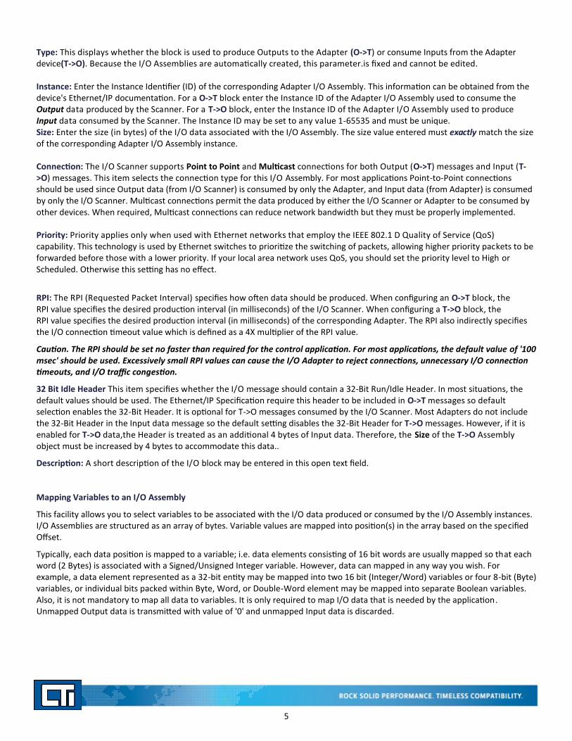
Variables are mapped to I/O Block data by selecting the I/O Assembly object and clicking on the Insert Variable button . This action will display the dialog box shown below.
Symbol: Select an existing variable using the 'Browse' button or enter an unused variable name to declare a new variable.
Data Exchange: Select this button to map the specified variable to the I/O data.
Offset: Enter the Byte offset where the variable will be mapped. For multi-byte data types (i.e. Integer, Real, etc.), this represents the starting offset position. For example, an Integer variable mapped to Offset 0 designates that the variable data corresponds to Offset positions 0-1. The mapping for the next variable starts at Offset 2. Offsets can also be automatically calculated using the Renumber offsets' facility described later in this document.
Format: Select the data format for mapping the designated positions in the I/O block data to the variable from the drop-down list.
When Bit is selected for the Format, you must specify the Offset byte and Bit number to map to the variable. In this case, that bit position is associated with an application variable such as a Boolean or Integer. All other data formats require that only the Offset byte be specified .
Diagnostic/Control: Select this button to map connection status/diagnostic data to application variable.
The selection of the following values are optional and in addition to mapping of data variables.However, it is highly recommended as a means up monitoring and tracking the operational status of the Ethernet/IP connection between I/O Scanner and Adapter device.
Server OK: A Boolean value that reports the status of the TCP/IP connection to the Server. TRUE = Server is connected. Note: A TCP connection between I/O Scanner and Adapter is required to initiate I/O messages. However, it is not required that this TCP connection be maintained while I/O data is transferred via UDP. Under some conditions, this connection may be closed and the I/O transfer continue to work normally.This
I/O Connection OK: A Boolean value that reports the status of the CIP I/O connection. TRUE = OK
Two additional facilities are provided to assist in Ethernet/IP I/O Scanner configuration:
Sort: Order in which variables are displayed may be sorted by offset byte position. Select I/O Assembly and click on the Sort
Variables button
Renumber Offsets: Offset positions are automatically calculated based on variable data type. Right -click on I/O Assembly and select Renumber offsets.
Specifying Configuration Data
Some I/O Adapters allow the data parameters within the I/O Assembly objects to be configured by the user. In most cases, the vendor also provides a software utility for setting these parameters.In other cases, the I/O Assembly parameters can be configured
7
by the I/O Scanner by using the Configuration Data object. Configuration data is sent as part of the communications sequence when establishing the I/O connection to the Adapter.
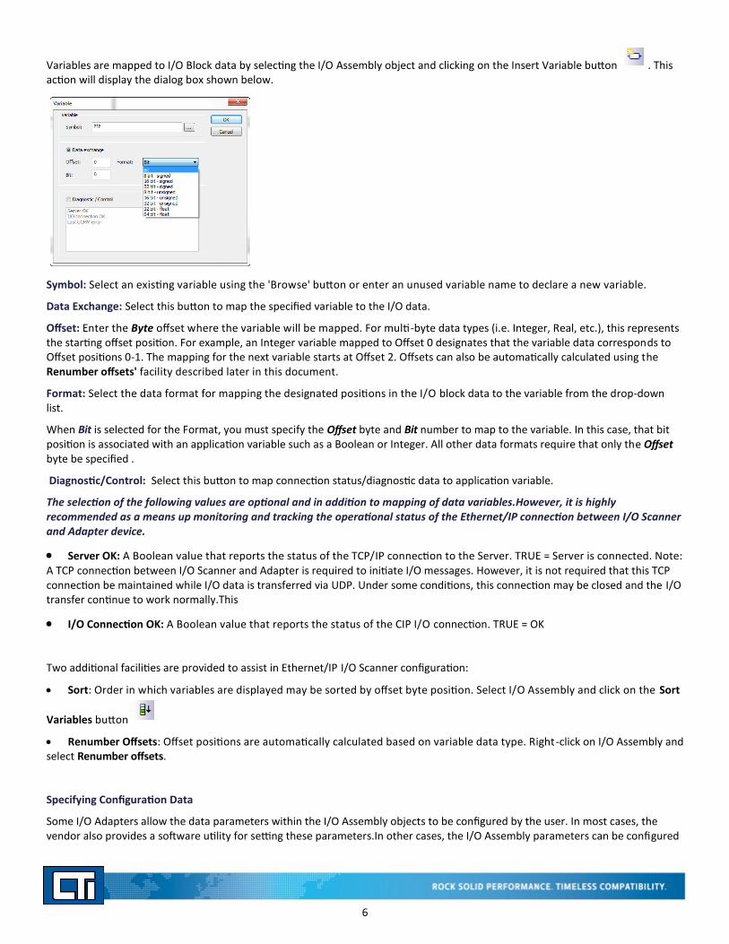
The Configuration object Instance is specified by double-clicking on the Adapter (Server) in the Configuration Tree:
Configuration Instance: Enter the Instance Identifier (ID) for the Configuration Data object. This information can be obtained from the Adapter's Ethernet/IP documentation. The Instance ID may be set to any value 1-65535 and must not duplicate Instance numbers entered for the O->T and T->O objects.
Edit: This button opens the Configuration Data Grid Editor described below.
Configuration Data Grid Editor
This editor allows you to specify data types and associated values to be sent as I/O configuration data.If no configuration data is required, this section can be omitted.
Configuration data is sent to the I/O Adapter as part of the 'Forward Open' message when the I/O connection is established.
Configuration data is configured by selecting the Type, Number of Items, and then entering Value for each element.
Type: Data type for configuration data. Only one data type may be selected. The data type can be changed by selecting a different type and can be deleted by selecting None. Configurations requiring multiple data types are described in the next example.
Nb Items: Number of elements of the designated data type. The number of bytes used by each item depends on the selected data type. The total amount of configuration data must be less than or equal to 400 bytes.

8
Little Endian: This determines the order of bytes when multi-byte elements are included in the configuration data downloaded to the Adapter. This box should always be checked .
Value: Data value for the configuration element. The value is entered by double-clicking on the cell.
Description: A short description of the item may be entered in this open text field.
Configuration data requiring items of more than one data type is set by creating a user-defined structure data type containing the
required elements. User-defined structures are defined using the editor accessed via the Open Types icon in the main toolbar. The following example shows the use of the structure data type:
A user-defined structure "EIPConfigData" was created with one BOOL, one INT, and one REAL element.
Press [Type] button and select the user-defined structure name from the drop-down list.
Each element of the structure is shown on a different line in the grid editor.
Assign a value to each structure element as shown in the example.
Description text for each element must be entered when the structure is created to be displayed in the grid editor.
CONFIGURING AN ETHERNET/IP TAG CLIENT
The Ethernet/IP Tag Client allows you to read and write data with in Allen-BradleyTM Logix controllers. The data must be contained in Controller Tags of global scope. Program (local) Tags cannot be accessed using this interface.
The Ethernet/IP Tag Client uses the CIP Data Table Read and CIP Data Table Write services. The Tag Client also implements the CIP Multiple Service Packet service, which improves performance by can embedding multiple Read Tag or Write Tag requests into one CIP message. In order to successfully configure the Tag Client, you must be knowledgeable of Allen-BradleyTM Logix data access facilities and the tags contained in the specific controller you wish to access.
The Ethernet/IP Tag Client is configured in the Fieldbus editing window. To open this window, click on the Open Fieldbus button on the Main Toolbar.

9
The Ethernet/IP Tag Client configuration objects are presented in a tree structure as illustrated below.
1. Ethernet/IP Tag Client This configuration object represents the protocol operation. If the Ethernet/IP Tag Client protocol does
not appear in the Fieldbus window, you can add it by clicking on the Insert Configuration toolbar button and selecting the protocol from the dialog box that is displayed.
2. Server: This object specifies a connection to a device that can service requests to read or write tags, such as an Allen -BradleyTM Logix controller.
3. Tag Request: This configuration object specifies the properties of a Tag Read or Tag Write request that will be transmitted to the device.
4. Variables: These objects specify the variables assigned to the data elements of the Tag array.
5. Control/Status: These objects specify variables assigned to control and status attributes.
Configuring a Connection to a Tag Server (usually an RSLogixTM Controller)
To specify a connection to a Tag Server, select the Ethernet/IP Tag Client object and click on Insert Master Port button on the local toolbar.
This action displays the dialog box shown below.
Address: Enter the IP Address of the Tag Server (usually A-B Logix controller)
Description: A short description, such as the device name/type, may be entered in this open text field.
Configuring a Tag Request
The configuration of the Tag Request consists of specifying the Request Mode (Read or Write), the Controller Tag information, and mapping of application variable(s) to the data packet transferred to/from the Tag Server. The CTI Tag Client provides two methods for configuring a Tag Request as shown below:
The first method allows the Tag Request and Variable Mapping operations to be done separately. This method must be used when individual application variables (as opposed to elements of a single array variable) are mapped to the Server Tag data.
Tag Request Data Block

10
To create a Tag Request data block, select the corresponding Tag Server connection object and click on the Insert Slave/ Data Block
button on the local toolbar. This action will display the dialog box shown below.
Mode: Select the request mode (Read Tag or Write Tag)
Tag Name: Enter the name of the Controller (Server) Tag to be read or written. The Tag name entered must match the Tag name in the Tag Server device.
Data Type: Select the Tag data type from the drop-down menu.The available data types match those supported by AB Logix controllers. The data type must match the data type in the Server device.
Nb. Elements:RSLogixTM tags used for data exchange are often structured as single dimension arrays of a given data type. Enter the number of Tag elements you wish to read or write.You can access any number of Controller Tag elements (at least one) up to the number of elements in the array. The starting point can be set for any element position (see Offset below).. If 'Number Elements' plus the 'Offset' value specified below results in a request to read non-existing element(s) in the Server Tag, an error response will be returned.
Offset: This specifies the starting Byte offset of the Controller Tag array to be accessed by the Tag Request.The first byte in the data block is Offset 0.This value represents the offset position within the Tag array- not the element number.
For example, the first element of an "Integer" Controller Tag array occupies offset positions 0-1. The second "Integer" element is stored in offset positions 2-3. Therefore, the first element can be ignored by entering "2" as the Offset value. Offsets for all elements can be automatically calculated via the 'Renumber offsets' facility described later in this document.
PLC Slot: This item specifies the location of the Ethernet port on the RSLogix controller. When accessing the PLC via a communications adapter module, the slot location where the communications adapter is located should be entered. This information is used to route the request between the communications module and the controller via the backplane. When accessing the PLC via a local Ethernet port on the CPU, set this value to '0'.
Request Period: Enter the time interval (in milliseconds) between successive requests. A value of 0 indicates that the request will be initiated using program logic using the Send Request Now trigger described in the Diagnostic/Control section below.
Timeout: Enter the time interval (in milliseconds) to wait for a response from the Tag Server before declaring a timeout error.

11
Mapping Variables to Server Tag Data
To map an application variable to the Server Tag data block, select the Tag Request object and click on the Insert Variable button
on the local toolbar. The following dialog box is displayed. This operation may be repeated as necessary to map the entire data block.
Data Exchange
Select this option to map an application variable to Sever Tag data position(s). When selected, you can specify the following:
Symbol: This specifies the name of the variable to be mapped to one or more data elements that comprise data field sent to (or received from) the Controller Tag specified above. You can select an existing application variable using the browse button or create a new variable by entering an unused variable name.
Offset: This specifies the starting Byte offset within the data field.The first byte in the data block is Offset 0.This value represents the offset position within the Tag array- not the element number.
For example, the first element of an "Integer" Controller Tag array occupies offset positions 0-1. The second "Integer" element is stored in offset positions 2-3. Therefore, the first element can be ignored by entering "2" as the Offset value. Offsets for all elements can be automatically calculated via the 'Renumber offsets' facility described later in this document.
Format: Select the data format used to map the designated positions in the I/O block data to the variable from the drop-down list: Boolean, Bit, 8-bit Signed (SINT), 16-bit Signed (INT), 32-bit Signed (DINT), 16-bit Unsigned (UINT), 32-bit Unsigned (UDINT), 32-bit Float (REAL), or 64-bit Float (LREAL).
When Bit is selected, you must specify the Offset byte and Bit number to map to the variable. In this case, that bit position is associated with an application variable such as a Boolean or Integer. All other data formats require that only the Offset byte be specified.
Diagnostic/Control Variables
Select this button to map connection status or diagnostic data to an application variable. Each desired function must be mapped to a separate variable. The following table lists the status data and control functions associated with the Ethernet/IP Tag Client.
This selection is optional and in addition to mapping of data variables.However, it is highly recommended as a means to monitoring, debugging, and tracking the operational status of the Ethernet/IP connection between the Tag Client and Server device.

12
NOTE: CTI strongly recommends that variables be mapped to the 'General Status' and 'Extended Status' attributes of every Tag request. This is the only method available for determining the cause of errors that might occur. The Server OK and UCMM Busy attributes are global and need to be mapped only once per Server and these variables may be mapped into any Tag Request for the Server. The Transaction Counter is useful for confirming that Tag Requests are occurring as expected. The Send Request Now attribute is needed only if you are using logic to initiate a request.
The second configuration method configures all items in a single operation. Right click on the corresponding Server object and choose the Add Array Tag option from the drop-down menu to select this option. The following dialog box is displayed:
Information Description Server OK This is a Boolean value that reports the state of the TCP connec-
tion to the server. It is TRUE when the connection is OK.
UCMM Busy This is a Boolean value that indicates the availability of the UCMM (UnConnected Message Manager) service. The UCMM services Explicit messages that have no CIP connection. The Tag Client uses Unconnected Explicit Messages for CIP Data Table Read and Write requests. A value of TRUE indicates the UCMM is busy.
Send Request Now This control is used to initiate a CIP Data Table Read or Write request when the Request Period field in the Tag Request dialog box is set to 0 . The request is initiated when the Boolean varia-ble that is mapped to it transitions from FALSE to TRUE. This transition is treated as a "one-shot" and triggers a single request.
Transaction Counter This counter is incremented each time a Tag Request message is generated by the application.
General Status After a request completes successfully, a value of 0 will be written to the General Status variable. When an error is detect-ed, an error code is written to the General Status variable, See CIP Status Codes section for a list of error codes.
Extended Status Some errors also return an associated Extended Status Error code to provide more detailed reporting. See CIP Status Codes section for a list of error codes.

13
Add Array Tag
This option can be used to create a new Global application array variable and map its elements directly to the Server Tag data block.
Mode: Select the request mode (Read Tag or Write Tag)
Tag Name: Enter the name of the Tag to be accessed. The Tag name entered must match the Tag name in the Tag Server (or Controller).
Data Type: Select the data type from the drop down list. This data type must match the Server Tag and will also be assigned to the newly created application array variable .
Nb. Elements: RSLogixTM tags used for data exchange are often structured as single dimension arrays of a given data type. Enter the number of Tag elements you wish to read or write.You can access any number of Controller Tag elements (at least one) up to the number of elements in the array. The starting point can be set for any element position (see Offset below). The application array variable must be sized to contain at least the number of elements specified in this field. If 'Number Elements' plus the 'Offset' value specified below results in a request to read non-existing element(s) in the Server Tag or application variable, an error response will be returned..
Offset:This specifies the starting Byte offset of the tag array where the variable will be mapped. The first byte in the data block is Offset 0.For multi-byte data types (i.e. Integer, Real, etc.), this represents the starting offset position. For example, an Integer variable mapped to Offset 0 designates that the variable data corresponds to Offset positions 0-1. The mapping for the next variable starts at Offset 2. Offsets can also be automatically calculated using the Renumber offsets facility described later in this document.
PLC Slot: This item specifies the location of the Ethernet port on the RSLogix controller. When accessing the PLC via a communications adapter module, the slot location where the comm adapter is located should be entered. This information is used to route the request between the communications module and the controller via the backplane. When accessing the PLC via a local Ethernet port, set this value to 0.
IEC61131-3 variable: Enter the name for the new Global application array variable to be created. You cannot use the name of an existing variable wit this dialog window.
Request Period: Enter the time interval (in milliseconds) between successive requests. A value of 0 indicates that the request will be initiated using program logic. You must use the Send Request Now trigger described in the Diagnostic/Control section above to initiate the request.
Timeout: Enter the time interval (in milliseconds) to wait for a response from the Tag Server before declaring a timeout error.

14
NOTE: Diagnostic/Control functions can also be added to Array Tags as described in the Diagnostic/Control section. Variables must be individually mapped to each desired function by selecting the corresponding function and clicking on the Insert Variable
button the local toolbar. See "Mapping Variables to Tag Requests " .
Two additional facilities are provided to assist in the Tag Client configuration:
Sort: Order in which variables are displayed may be sorted by offset byte position. Select Server Tag and click on the Sort
Variables button
Renumber Offsets: Offset positions are automatically calculated based on variable data type. Right-click on Server Tag and select Renumber offsets.
CIP Error Codes
The following errors may be returned by the Tag Client protocol manager. Error codes are in hexadecimal format. Decimal equivalents are shown in parenthesis.
Read Tag Errors
General Status Extended Status Description
0x04 (4) 0x0000 (0) Syntax Error in decoding Request Path
0x05 (5) 0x0000 (0) Request Path Destination Unknown. This usually indicates the Tag Name
does not exist in the Controller scope
0x06 (6) 0x0000 (0) Insufficient Packet Space. Not enough space in the response buffer for all
response data.
0x13 (19) 0x0000 (0) Insufficient Request Data. Data too short for expected parameters.
0x26 (38) 0x0000 (0) The request path size was shorter or longer than expected.
0xFF (255) 0x2105 (8453) Access beyond the end of object. The Number of elements requested plus
Offset exceeds the Number of elements in the Server Tag

15
Write Tag Errors
CONFIGURING AN ETHERNET/IP ADAPTER/SERVER
The Ethernet/IP Adapter/Server provides a means to exchange data with Allen-BradleyTM Logix controllers or other devices that can function as an I/O Scanner or CIP Generic Message Client.
When configured as an I/O Adapter, it communicates via Implicit I/O messages, consumes Output data produced by the Scanner, and produces Input data which is consumed by the Scanner. This interface is used primarily when repetitive, real-time data exchange is required.
When configured as an Explicit Message Server, it provides one or more Vendor Specific Objects containing data that can be read and written by the CIP Client.This Explicit Message interface is used for general purpose communications such as configuration, data access, and diagnostic status monitoring.This method is used when"on demand" data transfer is required (instead of continuous data updates) or when expanding/replacing existing system that utilize Ethernet/IP interface to the CTI 2572-A Ethernet Adapter.
The Ethernet/IP Adapter/Server operation is configured in the Fieldbus editing window.To open the FIeldbus configuration
window, click on the Open Fieldbus button on the Main Toolbar.
The configuration objects are presented as a tree structure illustrated below.
General Status Extended Status Description
0x04 (4) 0x0000 (0) Syntax Error in decoding Request Path
0x05 (5) 0x0000 (0) Request Path Destination Unknown. This usually indicates the Tag Name
0x10 (16) 0x2101 (8449) Device State Conflict: Keyswitch position. The requestor is attempting to
0x10 (16) 0x2102 (8450) Device State Conflict: Safety Status. The controller is in a state in which Safe-
ty Memory cannot be modified.
0x13 (19) 0x0000 (0) Insufficient Request Data. Data too short for expected parameters.
0x26 (38) 0x0000 (0) The request path size was shorter or longer than expected.
0xFF (255) 0x2105 (8453) Number of elements extends beyond the end of requested tag. The Number
of elements requested plus Offset exceeds the Number of elements in the
Server Tag.
OxFF (255) 0x2107 (8455) Tag Type used in request does not match the Server Tag data type.

16
1. Ethernet/IP Adapter: This object represents the protocol being configured. If the Ethernet/IP Adapter does not appear in the
Fieldbus window, you can add it by clicking on the Insert Configuration toolbar button and selecting the protocol from the dialog box that is displayed. When the Ethernet/IP Adapter is created, the Served I/Os and Objects level is automatically inserted into the tree structure since no configuration parameters are required for these two objects.
2. I/O Assembly:An I/O Assembly defines the cyclical data between the Scanner and Adapter using CIP Implicit (I/O) messaging. The O->T (Originator to Target) block specifies the Output data produced by the Scanner and consumed by the I/O Adapter. The T->O (Target to Originator) block specifies Input data produced by the I/O Adapter and consumed by the Scanner.
3. Vendor Specific Object: A Vendor Specific Object is used to create one or more data groups that can be accessed (read or written) using CIP Explicit Messages.
4. Variables:These configuration objects specify the variables mapped to an I/O Assembly or Vendor Specific Object.
Adding an I/O Assembly or Object
To add an I/O Assembly or Vendor Specific Object, select the Served I/O and Objects configuration object and click on the Insert
Slave Data Block button to display the I/O Object dialog box shown below.
Type: Select object type to be created from following list:
I/O: Outputs to add an O->T Assembly that will consume Outputs produced by a Controller/Scanner
I/O: Inputs to add a T->O Assembly that will produce data that is consumed by a Controller/Scanner
Vendor Specific Object to define a collection of data that can be accessed using CIP Explicit Messaging
Class: The Class Identifier (Class ID) is used only when configuring a Vendor Specific Object. The Class ID specifies a collection of data items. Usually, the Class ID is unique. However, it can be duplicated when more than one "instance" of the object is desired. CAUTION: To avoid conflict with other objects, Vendor Specific Objects should be assigned a class number in the Vendor Specific range: 100-199 (64-C7 Hex) or 768-1279 (300-4FF Hex).
Instance: The Instance Identifier (Instance ID) identifies a specific I/O Assembly or Vendor Specific Object.
For I/O Assemblies, the Instance ID must be unique and may be set to any value 1-65535 with the following restriction: Instance IDs 128-129 are reserved for future use and should not be assigned to I/O Assembly Objects.
When configuring Vendor Specific Objects, an Instance ID can be assigned in the range of 1 -65535. Within for a given Class ID, each Instance ID must be unique .For example,status information is needed for 3 different motors. First, create a Vendor Specific Object representing motor data to be reported and assign a Class ID. Then,configure 3 different instances of that Class ID to report data for each of the motors by mapping different variables to each instance.
Read Only: This parameter is used only with Vendor Specific Objects. Checking the Read Only box will prevent an Explicit Message Client from writing to the corresponding object data.
Size: Enter the size (in bytes) of the I/O Assembly or Vendor Specific Object.

17
The size of I/O Assemblies (O->T or T->O data) must be in the range of 1-500 bytes. The 32-bit Run/Idle Header is included in this data size if selected . Therefore, the size of an I/O Assembly is limited 496 bytes if the Run/Idle Header is included.
The size of Vendor Specific Objects must be in the range 1-500 bytes. Additional size limitations may be imposed by the CIP data messages used to access these data objects.The actual length of data accessible via Explicit Messages depends on CIP routing path size and data length may be limited to approximately 486 bytes.
Description: A short description of the I/O block may be entered in this open text field.
Mapping Variables to an I/O Assembly or Vendor Specific Object
I/O Assemblies and the Vendor Specific Objects structure data as an array of bytes. Variable values are mapped into a position in the array based on the specified offset.
Typically, each data position is mapped to a variable; i.e. data elements consisting of 16 bit words are usually mapped so that each word (2 Bytes) is associated with a Signed/Unsigned Integer variable. However, data can mapped in any way you wish. For example, a data element represented as a 32-bit entity may be mapped into two 16 bit (Integer/Word) variables or four 8-bit (Byte) variables, or individual bits packed within Byte, Word, or Double-Word element may be mapped into separate Boolean variables. Also, it is not mandatory to map all data to variables. It is only required to map I/O data that is needed by the application. Unmapped Output data is transmitted with value of '0' and unmapped Input data is discarded.
Variables can individually assigned by selecting the corresponding Assembly Object and clicking on the Insert Variable button This action will display the dialog box shown below.
Symbol: Select an existing variable using the 'Browse' button or enter an unused variable name to declare a new variable.
Offset: Enter the Byte offset where the variable will be mapped. For multi-byte data types (i.e. Integer, Real, etc.), this represents the starting offset position. For example, an Integer variable mapped to Offset 0 designates that the variable data corresponds to Offset positions 0-1. The mapping for the next variable starts at Offset 2. Offsets can also be automatically calculated using the Renumber offsets facility described later in this document.
Format: Select the data format used to map the designated position(s) to the variable from the drop-down list:
Bit
8-bit Signed (SINT)
16-bit Signed (INT)
32-bit Signed (DINT)
8-bit Unsigned (BYTE)
16-bit Unsigned (UINT)
32-bit Unsigned (UDINT)
32-bit Float (REAL)
64-bit Float (LREAL)

18
Copyright© 2016 Control Technology Inc.
All Rights Reserved 21JAN2016
Control Technology Inc. 5734 Middlebrook Pike, Knoxville, TN 37921-5962 Phone: +1.865.584.0440 Fax: +1.865.584.5720 www.controltechnology.com
When Bit is selected for the Format, you must specify the Offset byte and Bit number to map to the variable. In this case, that bit position is associated with an application variable such as a Boolean or Integer. All other data formats require that only the Offset byte be specified .
Two additional facilities are provided to assist in Ethernet/IP Adapter/Server configuration:
Sort: Order in which variables are displayed may be sorted by offset byte position. Select I/O Assembly and click on the Sort
Variables button
Renumber Offsets: Offset positions are automatically calculated based on variable data type. Right -click on I/O Assembly and select Renumber offsets.
Explicit Message Client Services
The Explicit Message Client uses the following CIP services to access Vendor Specific Object data:
Vendor Specific Object Attributes
When accessing Vendor Specific Objects, the Explicit Message Client can access the following object attributes:
1 If the Object's Read Only box is checked, access is limited to 'Get all object data'.
Service Code Description
0E (hex) CIP Generic 'Get Attribute Single'
10 (hex) CIP Generic 'Set Attribute Single'
Attribute Access Description
1 Read Only Size (in bytes) of Vendor Specific Object
3 Read/Write All object data 1. The entire block of
data assigned to the Vendor Specific
Object is read/written with each mes-
sage.


![[PPT]Fast Ethernet and Gigabit Ethernet - WPIweb.cs.wpi.edu/~rek/Undergrad_Nets/B04/Fast_Ethernet.ppt · Web viewFast Ethernet and Gigabit Ethernet Fast Ethernet (100BASE-T) How to](https://img.pdfslide.us/doc/110x75/5b29d4a97f8b9aad2f8b4e9d/pptfast-ethernet-and-gigabit-ethernet-rekundergradnetsb04fastethernetppt.jpg)