Embed Size (px)
Citation preview

Using Emulation to Understand and ImproveWireless Networks and Applications
Glenn Judd and Peter Steenkiste∗
Carnegie Mellon UniversityPittsburgh, PA, USA
[email protected] [email protected]
AbstractResearchers have long faced a fundamental tension be-tween the experimental realism of wireless testbeds onone hand, and the control and repeatability of simula-tion on the other hand. To overcome the stark tradeoff ofthese traditional alternatives, we are developing a wire-less emulator that enables both realistic and repeatableexperimentation by leveraging physical layer emulation.
We discuss the design and implementation of a proto-type wireless emulator, and show how this emulator canbe leveraged to provide insight into wireless network andapplication behavior. Our experience shows that, com-pared to simulation, our emulator-based approach pro-vides us with a better understanding of real-world wire-less network performance, and enables us to quickly de-ploy our research into an operational wireless network,while still allowing us to enjoy the benefits of a con-trolled experimental environment.
1 IntroductionAs wireless network deployment and use become ubiq-uitous, it is increasingly important to make efficient useof the finite bandwidth provided. Unfortunately, researchaimed at evaluating and improving wireless network pro-tocols and applications is hindered by the inability to per-form repeatable and realistic experiments. Experimen-tal techniques that have proven successful for wired net-works are inadequate for wireless networks since a wire-less physical layer fundamentally affects operation at alllayers of the protocol stack in complex ways. Links areno longer constant, reliable, and physically isolated fromeach other, but are variable, error-prone, and share a sin-gle medium with each other and with external uncon-trolled sources.
An ideal method of wireless experimentation wouldpossess the following properties: repeatability and ex-perimental control, layer 1-4 realism, the ability to runreal applications, configurability, the ability to modifywireless device behavior, automation and remote man-agement, support for a large number of nodes, isolationfrom production networks, and integration with wirednetworks and testbeds. We now discuss how alternative
∗This research was funded in part by the NSF under award num-bers CCR-0205266 and CNS-0434824. Additional support was alsoprovided by Intel. Glenn Judd is supported by an Intel Fellowship.
methods of experimentation fare with respect to this listof desirable properties.
The most direct method of addressing realism is toconduct experiments using real hardware and softwarein various real world environments. Unfortunately, thisapproach faces serious repeatability and control issuessince the behavior of the physical layer is tightly cou-pled to the physical environment and precise conditionsunder which an experiment is conducted. The mobilityof uncontrolled radio sources, physical objects, and peo-ple makes these conditions nearly impossible to repro-duce. Even repeating the same experiment twice can bea daunting task when anything in the surrounding envi-ronment is in motion; remote researchers face an evenbleaker situation trying to reproduce an experiment. Itis also difficult to avoid affecting colocated productionnetworks. Moreover, configurability and management ofeven a small number of mobile nodes distributed in threedimensions is cumbersome.
For these reasons, many researchers have understand-ably embraced simulation. This approach solves theproblems of repeatability, configurability, manageability,modifiability, and (potentially) integration with externalnetworks, but faces formidable obstacles in terms of real-ism. Wireless simulators are confronted with the difficulttask of recreating the operation of a system at all lay-ers of the network protocol stack as well as the interac-tion of the system in the physical environment. To makethe problem tractable, simplifications are typically madethroughout the implementation of the simulator. Evenfundamental functions such as deciding what a receivedframe looks like [1] diverge greatly from the operationof real hardware. Evaluating real applications runningover wireless networks is typically very difficult using asimulator. In addition, while wireless technology is un-dergoing rapid advances, wireless simulators, in particu-lar open source wireless simulators, have lagged signifi-cantly behind these advances as discussed in Section 7.
The aforementioned issues with simulators, and a de-sire to avoid long simulation times, have caused someresearchers to adopt emulation as a means of evaluation.Emulation retains simulation’s advantages of repeatabil-ity and manageability, while potentially mitigating the is-sue of realism. Unfortunately, as discussed in Section 7,most emulators have adopted extremely simplified MAC

and physical layers. As the operation of these layers isfundamental to the operation of a wireless network, it isunclear that these emulators gain any realism over exist-ing simulators.
We are developing a wireless emulator that enablesboth realistic and repeatable wireless experimentationby accurately emulating wireless signal propagation ina physical space. Unlike previous approaches, this emu-lator utilizes a real MAC layer, provides a realistic phys-ical layer, and supports real applications while avoid-ing adopting an uncontrollable or locale-specific archi-tecture. The key technique we use to accomplish this isdigital emulation of signal propagation using an FPGA.
Our emulator’s high degree of control and fidelity al-low signal propagation to be modeled in several ways:first, widely used statistical models of signal propagationcan be used; in addition, traces of observed signal prop-agation can be “replayed” on our emulator; lastly, man-ual control of signal propagation can be used to analyzebehavior in artificially created situations that would bedifficult or impossible to reproduce in an open system.Section 4 will discuss signal modeling in more detail.
This emulator provides an attractive middle groundbetween pure simulation and wireless testbeds. To alarge degree, this emulator should be able to maintainthe repeatability, configurability, isolation from produc-tion networks, and manageability of simulation while re-taining the support for real applications and much of therealism of hardware testbeds. As a result, this emulatorshould provide a superior platform for wireless experi-mentation.
This emulator is not, however, a complete replace-ment for simulation and real world evaluation. Simu-lation is still useful in cases where a very large-scale ex-periment is needed or in certain cases where functional-ity not available in hardware is required (e.g. changingthe MAC firmware). Real world evaluation is still usefulwhen radio channel fidelity beyond the capabilities of theemulator is required, or for verifying the operation of theemulator in real-world settings.
In this paper we present the design of a physical-layerwireless emulator. We introduce the architecture of thisemulator in Section 2. In Section 3 we discuss an initialproof-of-concept prototype, and our partially completeimplementation of a “Version 2” emulator based on thisproof-of-concept. Section 4 discusses how our emulatorcan be used to emulate various signal propagation en-vironments. Using both the prototype and the Version2 emulator, we present several experiments in Section 5and a case study in Section 6 that demonstrate the powerof our approach. Section 7 discusses related work, andSection 8 concludes our discussion.
SignalConversion FPGA Based
DSP Engine
Emulation Controller
SignalConversion
SignalConversion
SignalConversion
LO
Clock
Figure 1. Emulator Architecture
2 Emulator Architecture
The architecture of our emulator is shown in Figure 1. Anumber of “RF nodes” (e.g. laptops, access points, cord-less phones, oranywireless device in the supported fre-quency range) are connected to the emulator through acable attached to the antenna port of their wireless linecards (each RF node corresponds to a single antenna,so a single device can be represented by multiple RFnodes). For each RF node, the RF signal transmitted byits line card is “mixed” with the local oscillator (LO) sig-nal. This shifts the signal down to a lower frequencywhere it is then digitized, and fed into a DSP Engine thatis built around one or more FPGAs. The DSP Enginemodels the effects of signal propagation (e.g. large-scaleattenuation and small-scale fading) on each signal pathbetween each RF node. Finally, for each RF node, theDSP combines the appropriately processed input signalsfrom all the other RF nodes. This signal is then sent outto the wireless line card through the antenna port. Giventhe current state of technology, a DSP Engine based on asingle FPGA might support over 20 wideband RF nodes.Using multiple FPGAs or lower bandwidth RF nodes,even larger systems can be built.
The operation of the emulator is managed by the Em-ulation Controller, which coordinates the movement ofRF nodes (and possibly physical objects) in the emu-lated physical space. The Emulation Controller uses lo-cation information (and other factors as dictated by thesignal propagation model in use) to control the emulationof signal propagation within this emulated environment.In addition, the Emulation Controller coordinates node(and object) movement in physical space with the opera-tion of RF node applications and sending of data. EachRF node runs a small daemon that allows the EmulationController to control its operation via a wired network.RF nodes that are not capable of running code may re-quire a proxy to run the daemon on their behalf.
Connecting the Emulation Controller to an externalnetwork allows remote management of the emulator. Inaddition, individual nodes in the emulator may be con-nected to external networks in order to allow emulatornodes access to the Internet at large or to allow the em-ulator to be used in conjunction with testbeds such asPlanetLab [2] or Emulab [3].

Signal Conversion
Signal Conversion
Signal ConversionA/D
D/A
FPGA BasedDSP Engine
A/D
D/A
A/D
D/A
LO
Figure 2. Prototype Hardware Architecture
Input 1
Input 2
Input 3
Output 1
Output 2
Output 3
sf sf…
sf sf
sf sf
…
…
Delay Pipe
Delay Pipe
Delay Pipe
Figure 3. Prototype DSP Engine Operation
3 ImplementationTo demonstrate the feasibility of the wireless emulator,we constructed a small prototype designed to validatethe emulator’s primary functionality by emulating signalpropagation between three laptops on a single 802.11b“non-overlapping channel”. The results obtained withour prototype [4], in conjunction with MIT’s Roofnetproject [5], and experiments discussed in Sections 5and 6 show that the approach we advocate is capable ofproviding powerful wireless emulation capabilities.
We first discuss our prototype’s hardware and soft-ware implementation, and then discuss how Version 2improves on the capabilities demonstrated by the proto-type.
3.1 Proof-of-Concept Prototype
Hardware. Figure 2 shows the hardware architec-ture of the prototype. Each laptop operates on a sin-gle 802.11b channel centered at frequencyF which con-tains its main spectral elements fromF − 11MHz toF + 11MHz. The outgoing signal from each laptop isfirst attenuated and then converted to a low frequencyby “mixing” each signal with an “LO” signal centered atF − 13MHz. The resulting output from the mixers (ig-noring the signal image) is a signal ranging from 2 to 24MHz. This signal is then fed into an A/D board for sam-pling. Each A/D board generates 12-bit digital samplesof the incoming signal at 52 Msps, and sends them to theFPGA for processing. The output signals from the FPGAare converted to analog by the D/A and then “mixed up”and attenuated before arriving at the destination wirelesscard’s antenna port. We used two types of wireless NICs
in our prototype: antenna-less Orinoco Gold cards, andEngenius NL-2511CD Plus Ext2 Prism 2.5 based cardswhich both allow the connection of an external antennaor coaxial cable.
DSP Engine.As shown in Figure 3, inside the FPGA,the signals are first sent into a delay pipe where one ormore copies (“taps”) of the signal are pulled off after go-ing through a programmable amount of delay. Each ofthese signals is then scaled by a programmable factor.Each outgoing signal, from the FPGA to an RF node, isthen computed by summing the scaled signals from theother RF nodes. These outgoing signals are then sent tothe D/A board for reconstruction.
The programmable nature of this circuit allows us totrade off resources such as the precise depth of the delaypipes and number of signal copies supported. Thus, wecan customize the operation of the FPGA to the particu-lar test being run.
For each signal path inside of the FPGA, the Emu-lation Controller discussed below is capable of dynam-ically adjusting both the attenuation and delay from thesource to the destination by dynamically setting the scal-ing factors and delay mentioned previously at a rate ofapproximately 1,000 scale factors or 2,000 delay settingsper second. Hence, for each signal path, the emulator canrecreate effects such as “large-scale path loss” (a fixedattenuation that does not change unless RF node move-ment is emulated) and “fading” (rapid variation in signalstrength that can occur even if the device antennas aremotionless).
As the DSP Engine is implemented in an FPGA, theoperation described above, and used in the experimentspresented in this paper, may be changed as needed forparticular signal propagation models. For instance, fad-ing could be computed on the FPGA to allow for emula-tion of even faster fading.
Emulation Controller. The Emulation Controllercontrols and coordinates the operation of the DSP unitand the RF nodes, and runs in one of two modes: scriptor manual control.
In script mode, the Emulation Controller is drivenby scripts that specify each node’s movement, commu-nication, and application behavior. As the RF nodesmove about in the emulated physical space, the Emu-lation Controller continuously computes attenuation ofeach signal path and the scaling factors required to emu-late this attenuation (our prototype currently uses a sim-ple large-scale path loss model based on measurementsin our local environment). After computation, these scal-ing factors are sent to the DSP Engine. Emulation Con-troller scripts can also generate network traffic betweenany pair of nodes, and synchronize this traffic with nodemovement and application behavior.
DelayRSS
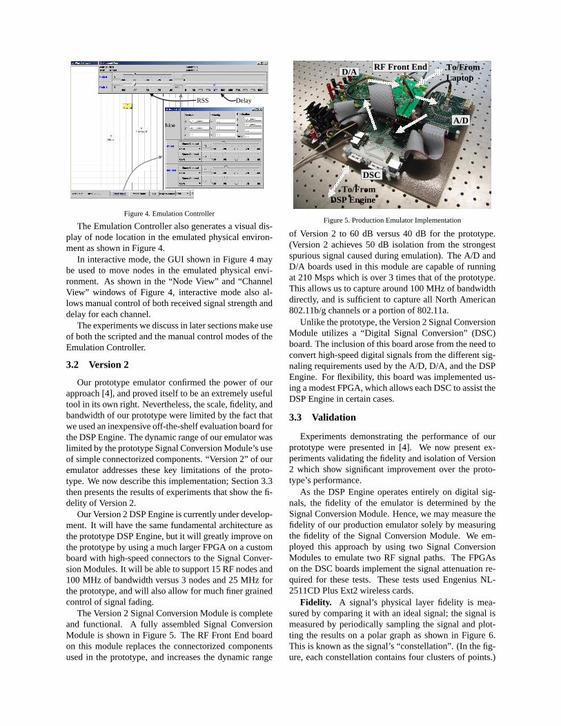
Figure 4. Emulation Controller
The Emulation Controller also generates a visual dis-play of node location in the emulated physical environ-ment as shown in Figure 4.
In interactive mode, the GUI shown in Figure 4 maybe used to move nodes in the emulated physical envi-ronment. As shown in the “Node View” and “ChannelView” windows of Figure 4, interactive mode also al-lows manual control of both received signal strength anddelay for each channel.
The experiments we discuss in later sections make useof both the scripted and the manual control modes of theEmulation Controller.
3.2 Version 2
Our prototype emulator confirmed the power of ourapproach [4], and proved itself to be an extremely usefultool in its own right. Nevertheless, the scale, fidelity, andbandwidth of our prototype were limited by the fact thatwe used an inexpensive off-the-shelf evaluation board forthe DSP Engine. The dynamic range of our emulator waslimited by the prototype Signal Conversion Module’s useof simple connectorized components. “Version 2” of ouremulator addresses these key limitations of the proto-type. We now describe this implementation; Section 3.3then presents the results of experiments that show the fi-delity of Version 2.
Our Version 2 DSP Engine is currently under develop-ment. It will have the same fundamental architecture asthe prototype DSP Engine, but it will greatly improve onthe prototype by using a much larger FPGA on a customboard with high-speed connectors to the Signal Conver-sion Modules. It will be able to support 15 RF nodes and100 MHz of bandwidth versus 3 nodes and 25 MHz forthe prototype, and will also allow for much finer grainedcontrol of signal fading.
The Version 2 Signal Conversion Module is completeand functional. A fully assembled Signal ConversionModule is shown in Figure 5. The RF Front End boardon this module replaces the connectorized componentsused in the prototype, and increases the dynamic range
A/D
D/A
To/FromDSP Engine
RF Front End To/FromLaptop
DSC
Figure 5. Production Emulator Implementation
of Version 2 to 60 dB versus 40 dB for the prototype.(Version 2 achieves 50 dB isolation from the strongestspurious signal caused during emulation). The A/D andD/A boards used in this module are capable of runningat 210 Msps which is over 3 times that of the prototype.This allows us to capture around 100 MHz of bandwidthdirectly, and is sufficient to capture all North American802.11b/g channels or a portion of 802.11a.
Unlike the prototype, the Version 2 Signal ConversionModule utilizes a “Digital Signal Conversion” (DSC)board. The inclusion of this board arose from the need toconvert high-speed digital signals from the different sig-naling requirements used by the A/D, D/A, and the DSPEngine. For flexibility, this board was implemented us-ing a modest FPGA, which allows each DSC to assist theDSP Engine in certain cases.
3.3 Validation
Experiments demonstrating the performance of ourprototype were presented in [4]. We now present ex-periments validating the fidelity and isolation of Version2 which show significant improvement over the proto-type’s performance.
As the DSP Engine operates entirely on digital sig-nals, the fidelity of the emulator is determined by theSignal Conversion Module. Hence, we may measure thefidelity of our production emulator solely by measuringthe fidelity of the Signal Conversion Module. We em-ployed this approach by using two Signal ConversionModules to emulate two RF signal paths. The FPGAson the DSC boards implement the signal attenuation re-quired for these tests. These tests used Engenius NL-2511CD Plus Ext2 wireless cards.
Fidelity. A signal’s physical layer fidelity is mea-sured by comparing it with an ideal signal; the signal ismeasured by periodically sampling the signal and plot-ting the results on a polar graph as shown in Figure 6.This is known as the signal’s “constellation”. (In the fig-ure, each constellation contains four clusters of points.)

DSGEVM: 2.1%
DSG-EmulatorNarrowband180 MHzEVM: 2.2%
DSG-EmulatorWideband180 MHzEVM: 2.1%
(a) (b) (c)
Figure 6. Physical Layer Fidelity
We can then visually compare the measured constellationagainst an ideal constellation.
We can quantify the difference between a measuredsignal and an ideal signal by measuring “error vectormagnitude” (EVM). EVM is the relative difference be-tween ideal signal constellation points and observed con-stellation points. EVM measures the average magnitudeof the error vector (a vector from the ideal constellationpoint to the observed point) as a percentage of the idealsignal vector’s magnitude.
Figure 6 compares the modulation fidelity of a signalgenerated by a digital signal generator (a) with that ofthe same signal passed through our production emulator(b) and (c). Comparing (a) with (b) we see that whenthe emulator is digitizing in narrowband mode (a single802.11b channel) the constallation loses some crispness,but is still excellent; EVM increases slightly. (c) showsthat when digitizing a wideband signal (802.11b chan-nels 1-11) the signal degrades slightly more, but is stillquite good. The EVM measurement in this case shouldnot be regarded as saying that there is no signal degrada-tion in wideband mode, but merely shows that the degra-dation is within the margin of measurement error.
Our earlier prototype work [4] demonstrated that ouremulator does not distort on-card measurements such asreceived signal strength (RSSI). This previous work alsoshowed that the prototype link delivery performance wasclose to that of a coaxial-based comparison, and that sig-nal modeling was repeatable across experiments. Weomit similar tests from this work in the interest of space.
Figure 7 demonstrates that our prototype’s physicaland link layer fidelity translates into transport level fi-delity by comparing the TCP throughput for two laptopsconnected via coaxial cable and discrete attenuators ver-sus two laptops connected via our production emulator.Each data point is an average of 20 trials measuring one-way TCP throughput for approximately 5 seconds. Con-fidence intervals are omitted since they are tight, and theSNR measurement error is dominant (about 1 dB). Theresults match quite closely and are within the measure-ment error of the experiment.
Isolation. An important benefit of our prototype is theability to conduct experiments in isolation from externalsources of interference. To measure this, we used a high
0
0.5
1
1.5
2
2.5
3
3.5
4
4.5
5
0 2 4 6 8 10 12 14 16
SNR (dB)
Thro
ughp
ut (M
bps)
EmulatorCoaxial-based
Figure 7. Transport Layer Fidelity
power source (20 dBm) external to our emulator with astrong omnidirectional antenna (5.5 dBi) to send trafficat 1Mbps. We then moved this traffic source around ourimmediate environment to see when our emulator couldnot sense any of this traffic. Our results showed that ouremulator was isolated against this strong source when itwas at least 10 meters away. The current limitation onthis isolation is the need to sacrifice perfect shielding inorder to allow the RF nodes to be cooled. Additionalwork should cut the interfering range down to a few me-ters even for strong transmitters.
Building a large setup requires that we place RF nodesin close proximity to each other. To allow for this whilemaintaining internal isolation, each emulator node ismounted inside of a shielded rack-mount chassis. By al-tering the external isolation test to measure internal iso-lation, we verified that nodes attached to the emulatorare effectively isolated against undesired transmission toeach other despite their close proximity (8.75 inches).
We next discuss how our emulator’s ability to faith-fully control the wireless signal is used to model signalpropagation. We will then discuss several experimentsthat demonstrate the range of experiments enabled by ouremulator.
4 Signal Propagation Modeling
With our ability to completely control wireless signalpropagation comes the challenge of modeling or recre-ating propagation in an appropriate manner for a givenexperiment. Our goal in this work is not to develop andjustify new physical models of signal propagation, but todiscuss how current and future models as well as signalpropagation trace playback can be used in our emulator.
Fortunately, unlike wireless simulators, we are freedfrom the task of emulating radio behavior in conjunc-tion with signal propagation modeling: we simply picka suitable signal propagation model, compute each re-ceiver’s received signal, and let the radio decide whathappens. We do not need to make any assumptions re-garding any radio issues such as “sensing range”or “in-terfering range”.

We now discuss several different methods of model-ing wireless signal propagation in our emulator. We be-gin with signal propagation models that require no sitespecific information, and then discuss models that useincreasing amounts of site specific information. Some ofthese techniques are completely operational in our em-ulator (large-scale path loss, signal capture and replay),some are partially operational (small-scale fading), whileothers require some external tools before they can beused in our emulator (ray-tracing, channel sounding).
4.1 Large-scale Path Loss
The signal propagation model most commonly usedby simulators is a large-scale path loss model. Specifi-cally, the received signal strength at each receiver (RSS)is computed asRSS = Pt + Gt − PL + Gr. WherePt and Gt are the transmit power and antenna gain at thetransmitter, PL is the path loss, and Gr is the antenna gainat the receiver. Large-scale path loss models simply com-pute PL as a function of distance between the transmitterand the receiver.
The Emulation Controller implements large-scalepath loss by simply calculating the loss between nodeswhenever the distance between them changes. These lossvalues are then sent into the emulator where they are usedto control the attenuation of the signal path between twonodes.
4.2 Small-scale Fading
While large-scale fading models can accurately cap-ture the average path loss between two points, on a shorttime scale the path loss between these points may varysubstantially. To support this behavior, we are currentlyadding the ability in our emulator to emulate this small-scale fading.
We are leveraging the technique presented in [6] toincorporate the Ricean and Raleigh statistical models ofsmall-scale fading in our emulator. In our implementa-tion, the fading parameters are computed offline, and arethen loaded into our emulator’s FPGA before emulationbegins. At run time, these parameters are added to thelarge-scale path loss which causes short term variationwith the desired statistical properties. Independent useof fading parameters should allow independent, on-linemodification of small-scale fading for each RF node.
4.3 Ray TracingThe previous two methods required no site specific in-
formation other than picking the correct path loss modelsand model parameters. By incorporating site-specific in-formation, it is possible to generate more accurate signalpropagation models.
One technique that can be implemented in the emu-lator is to leverage ray tracing techniques. If the motion
-110
-105
-100
-95
-90
-85
-80
-75
-70
-65
-60
0 5 10 15 20 25
Time (seconds)
RS
S (
dBm
)
Figure 8. Freeway Driveby Measured RSS
of nodes can be pre-computed off-line, ray-tracing tech-niques can be used to precisely compute all rays incidenton each receiver at a given point in time. If motion can-not be pre-computed, then approximations can be made.
At runtime, the pre-computed series of attenuationover time values for each signal path would then be usedto set path attenuation inside the DSP Engine.
4.4 Capturing and Replaying Signal BehaviorOne simple method of accurately modeling signal
propagation is to measure the signal propagation in agiven environment and then to replay it. We have imple-mented a signal capture system using standard wirelessNICs that measures path loss in a physical environment.This system works by constantly sending small packetsfrom each transmitter to be emulated and receiving thesepackets on each receiver being emulated.
Our emulator then simply replays the observed tracesof signal strength. To demonstrate this capability, wecaptured path loss from a car driving along a freewayat 60 MPH to a base station located at a fixed point nearthe freeway.
The traffic source was a 23 dBm 802.11b source at-tached to a 5 dBi isotropic antenna placed on the roof ofthe passing car. The receiver used the same hardware asthe sender, but with the antenna placed on the roof of astationary car at the side of the freeway. As the senderpassed, it continuously broadcast small 1 Mbps broad-cast packets which were recorded by the receiver. Theresult of this test was signal strength measurements with1 ms granularity. We then post-processed this trace toextract the timestamped signal and noise measurements.
Figure 8 shows the trace extracted using this method.Our emulator then simply reads, and recreates the ob-served path loss at the given time. Our current trace re-playing software is limited to 2.5 ms granularity.
4.5 Channel Sounding
A more sophisticated method of measuring signalpropagation in a physical environment is to use spe-

cialized hardware to precisely measure the “impulse re-sponse” of the channel. Such measurements can be dif-ficult to obtain since they require specialized hardware.Once obtained, however, our emulator is capable of re-playing these measurements by setting the attenuationand delay of each signal path in the DSP Engine accord-ing to the values extracted from the channel sounding.
4.6 Discussion
Before presenting experimental results, we briefly dis-cuss the capabilities and limitations of signal propagationmodeling using our approach.
Simulation. Many of the signal propagation modelsthat we utilize can be also be used in simulation. This su-perficial similarity, however, belies a massive differencein how these models are used. Computational constraintsplaced on a simulator, force the simulator to work at avery coarse timescale. Our emulator, on the other hand,uses a statistical propagation model to manipulate a realmodulated signal on the timescale of 5 ns. This is thensent to a real receiver to determine the reception behav-ior. Accurate receiver behavior in a simulator would re-quire transistor level simulation which is completely in-feasible for the number of nodes that we are looking at.Realtime simulation of such behavior is out of the ques-tion.
Similarly, while a simulator can replay a capturedchannel trace, it can only do so at a very coarse timescaleand with far less fidelity than a physical layer emulator.
Real-world experimentation. The ability to pre-cisely recreate a signal propagation environment is ahuge advantage compared to real-world experimentation.This power, however, comes with a price of reduced re-alism and scale in signal propagation.
Our approach necessarily models a wireless channelusing discrete elements (e.g. one line-of-sight ray andtwo reflections) whereas a true wireless channel is a con-tinuous phenomenon. Also, as the number of RF nodesattached to our DSP Engine increases, the number andlength of delayed signal paths that we can implementdrops. Hence our approach is a compromise between thefidelity of the real-world and the control of simulation.
Noise. The term noise is frequently used to refer toboth true noise (e.g. receiver noise) and interferencefrom other wireless devices. Receiver noise is naturallypresent in our system since we use real receivers. Inter-ference from other wireless devices can be supported inseveral ways. First, if RF Node ports are free and the de-vices are available, these devices can simply be attachedto our emulator. Secondly, it is possible to record noiseresulting from interference and to replay this in the emu-lator. Third, a white noise generator can be implementedin either the DSP Engine or the DSC card to generatenoise.
Note that our effective receiver noise floor will beslightly higher than a coaxial based system since we useadditional amplifiers etc. that introduce noise. This levelwill still be much lower than the noise floor of a truefree-space wireless system.
Scale. As hardware is finite, the richness of chan-nel modeling possible using hardware-based emulationdrops as the scale of the network being emulated in-creases. The limiting factor is typically the number ofmultipliers in the DSP Engine’s FPGA.
For much of our discussion, we have assumed the de-sire to support the independent pairwise emulation ofall pairs of RF Nodes attached to an emulator. Clearlythis approach becomes infeasible at a certain point as thecomplexity of pairwise interaction is ordern2.
It is important to observe, however that emulatingcomplete interaction is not always necessary. Clearly, ifnodes are out of range with respect to each other, then noemulation between them is necessary. In addition, com-plexity may be reduced by simplifying and aggregatingthe emulation of channels for distant nodes.
Multi-element Air Interface Support. Current wire-less networks are pushing the limits of the throughputthat are possible with a single element antenna. Futurenetworks will increase throughput by using multiple ele-ments to support techniques such as steerable antennas,MIMO, and “time reversal”.
Our emulator can support such emerging technologiesin two ways. First, where hardware exists, our emulatorcan support these multi-element experiments by simplytreating each element as an independent RF node. Thecontrol software then simply controls these RF nodes ina coordinated fashion which also opens up some roomfor reducing FPGA resources consumed. Second, in cer-tain circumstances, it may be possible for the emulatorto emulate the effect of a given technology. For instance,a steerable antenna can be completely emulated withoutnecessarily using a true steerable NIC.
5 Experiments
Our emulator enables a broad set of experiments to beconducted in a controlled and automated environment.To give a feel for the power of our emulator as a researchtool, we now present several experiments that illustratevarious types experimentation that our emulator enables.
We first discuss how our emulator can improve under-standing of the impact of the physical layer on higher lay-ers. We then discuss our emulator’s support for emergingantenna and air interface technologies. Finally, we dis-cuss how our emulator can be used to conduct micro andsystem level benchmarks of wireless performance. Sec-tion 6 will then present a case study showing how our

emulator can be used to analyze a wireless protocol im-provement.
These experiments were all conducted using one ormore of three RF Nodes connected to our prototype: “Or-chid”, “Hermes”, and an interferer (“Nice” or a Blue-tooth source). For experiments conducted in an emu-lated physical environment (i.e. where manual control ofchannel parameters is not required), we use a log-basedpath loss model derived from our local environment. Foreach of the experiments discussed, obtaining realistic re-sults using traditional methods would be difficult or in-accurate.5.1 Physical Layer Impact on Higher Layer
Performance5.1.1 Hidden Terminal
Orchid HermesNice50 m 30 m
Figure 9. Hidden Terminal Topology
0
0.5
1
1.5
2
2.5
3
3.5
4
4.5
5
No RTS No RTS No RTS RTS RTS
NoInterference
Interference Interference Interference NoInterference
Not Hidden Hidden
Thro
ughp
ut (M
bps)
Figure 10. Hidden Terminal Results
A well known example of a low layer issue that haspotentially serious ramifications for application perfor-mance in wireless networks is the “hidden terminal”problem. Evaluating the hidden terminal problem in areal world environment is troublesome since it is difficultto determine if nodes are in carrier sensing range of eachother. Moreover, carrier sensing range constantly fluc-tuates in the real world. This experiment highlights ourprototype’s ability to overcome these difficulties by pro-viding precise, independent control over the signal pathsbetween all nodes. This allows us to evaluate the hiddenterminal problem by simply commanding the emulatorto “disconnect” the desired nodes while leaving the com-munication between other nodes unaffected.
As illustrated in Figure 9 we arranged our three nodesin a line with all nodes in range of each other. (For sim-plicity we will speak of spatial relationships in our virtualphysical environment as if they were based in a real phys-ical environment). We then measured TCP throughput
from Hermes to Orchid while Nice was used to generateinterfering traffic using a unicast ping flood directed atOrchid. Orinoco cards were used for these tests.
As shown in the Figure 10 “No RTS, No Interference”test, throughput between Orchid and Hermes is excellentwhen there is no interference (each value is an averageof 25 trials with 95% confidence intervals shown). Inthe “No RTS, Interference, Not Hidden” test, we see thatwhen Nice begins interfering, throughput is still quitegood (ping packets are much smaller than the TCP pack-ets).
We then created a hidden terminal situation by ar-tificially “severing” the link between Hermes and Nicewhile leaving the other communication paths unaffected.(The ability to create a hidden terminal situation with-out “moving” the nodes allows us to directly compareresults between the hidden and non-hidden tests.) The“No RTS, Interference, Hidden” test shows that through-put between Orchid and Hermes drops dramatically inthis case.
We next analyzed the efficacy of 802.11’s RTS/CTSmechanism at overcoming the hidden terminal problemby repeating the previous tests with Hermes set to alwaysuse RTS/CTS for frames over 200 bytes. The “RTS, In-terference, Hidden” test shows that RTS/CTS is able todouble throughput; nevertheless throughput is still muchlower than when the interferer was not hidden. Compar-ing the final “RTS, No Interference” test with the “NoRTS, No Interference” case shows that the overhead ofRTS/CTS alone is roughly 1 Mbps. Further investigation(and coaxial-based verification) revealed that the causeof this underwhelming improvement was the failure ofRTS/CTS to prevent rate fallback. The ability to analyzethis type of subtle behavior in a controlled environmentis a key advantage of our emulator.
5.1.2 External InterferenceAnother well known problem that can afflict wireless net-works in a license free band is interference from externalsources. To illustrate our ability to investigate interfer-ence from arbitrary sources we conducted a simple ex-periment involving two 802.11b nodes communicatingin the face of interference from a Bluetooth source. Asshown in Figure 11, each node was positioned 50 metersfrom the other two nodes.
Figure 12 shows the results of communication be-tween Hermes and Orchid for four scenarios (each valueis an average of 25 trials with 95% confidence intervalsshown), two of which - the “Yagi” cases - will be dis-cussed in the next section.
In the “Isotropic, No Interference” test, Hermes andOrchid communicate with omnidirectional antennas withno interference (using a TCP benchmark with trafficfrom Orchid to Hermes). Communication is only around1.25 Mbps due to the distance between the nodes.

Orchid
Hermes
Bluetooth-likeSource
50 m
50 m
50 m
18 dBi Yagi antenna radiation pattern
Figure 11. Directional Antenna Topology
00.5
11.5
22.5
33.5
44.5
5
Isotropic Isotropic Yagi Yagi
No Interference Interference No Interference Interference
Thro
ughp
ut (M
bps)
Figure 12. Directional Antenna Results
In the “Isotropic, Interference” test, Hermes and Or-chid communicate as before, but the Bluetooth sourceis configured to broadcast a constant 15 dBm signal withBluetooth modulation. TCP communication between Or-chid and Hermes is not possible in this case.
5.2 Flexible Antenna and Multi-element Air In-terface Support
Complete control over signal propagation also allowsour prototype to emulate arbitrary types of antennas. Toillustrate this, we analyzed the ability of directional an-tennas to improve range and spatial reuse by minimiz-ing the effects of interfering Bluetooth traffic (discussedin 5.1.2). Orinoco cards were used for these tests.
The “Yagi” tests repeat the “Isotropic” tests discussedpreviously, but with 18 dBi Yagi antennas [7] attachedto Orchid and Hermes. These antennas are aimed di-rectly at each other. Figure 11 shows the radiation pat-tern for these antennas. Note that for Orchid and Hermes,the Bluetooth source lies along a side lobe with approx-imately 22 dB and 18 dB respectively less gain than theprimary lobe. As shown in Figure 12 these directionalantennas successfully increase the communication rateand also mitigate the effects of external interference.
5.3 Benchmark ExperimentsWe now consider “benchmark” experiments that are
designed to measure particular aspects of wireless NICor link behavior. In additon to providing the control nec-essary for these tests, the emulator allows these tests tobe automated which greatly reduces execution time whileeliminating the error associated with manually conduct-ing similar experiments.
These capabilities also enabled us to compare wire-less link behavior observed in Roofnet [5] against linkbehavior in a controlled emulated environment.1
5.3.1 NIC Signal Measurement CharacterizationMany researchers have proposed techniques that relyon signal strength and/or noise floor measurements pro-vided by the card. Two common examples are signalstrength based device location [8] and SNR based rateselection [9]. The success of these proposed techniqueshinges on the accuracy of NIC signal measurement; verylittle information, however, has been published regardingthe accuracy of these measurements in actual hardware.
To investigate the accuracy of signal measurementsmade by current 802.11b cards, we tested the measure-ment behavior of five wireless cards. Each card was theexact same model: an Engenius NL-2511CD Plus Ext2card. Using our emulator to connect a single transmitter-receiver pair we were able to precisely control the re-ceived signal strength (RSS) at each card (we held thetransmitter constant while alternately measuring each re-ceiver). For each signal strength between -70 dBm and-100 dBm at 2 dB intervals we sent 500 packets of 1500bytes each at 1 Mbps. We then computed the averagesignal strength (RSSI) and noise measured by each card(along with 95 % confidance intervals).
0
5
10
15
20
25
30
35
40
-100 -95 -90 -85 -80 -75 -70RSS (dBm calculated)
RS
SI
00:02:6f:07:30:6400:02:6f:04:a8:cf00:02:6f:04:a8:c700:02:6f:04:a8:ce00:02:6f:04:a8:d2
Figure 13. Per-card RSSI Variation
As shown in Figure 13 there is approximately 10 dBof variation in the measurements even for the exact samemodel of card. This is clearly inadequate for many pur-poses. For most cards, however, this variation seemsto be caused by a constant bias. This implies that eachcard’s measurement behavior, RSSI, for a given RSS canbe defined as:RSSI(RSS) = RSS + Ec + E(RSS).Where RSSI is the measured signal strength, RSS is theactual signal strength, Ec is a constant (per-card) errorterm, and E(RSS) is each card’s variation of from the
1This was done in conjunction with the Roofnet project

0
2
4
6
8
10
12
14
-100 -95 -90 -85 -80 -75 -70RSS (dBm calculated)
Sile
nce
00:02:6f:07:30:6400:02:6f:04:a8:cf00:02:6f:04:a8:c700:02:6f:04:a8:ce00:02:6f:04:a8:d2
Figure 14. Per-card Noise Variation
0
5
10
15
20
25
30
35
-100 -95 -90 -85 -80 -75 -70RSS (dBm calculated)
SN
R (R
SS
I - S
ilenc
e)
00:02:6f:07:30:6400:02:6f:04:a8:cf00:02:6f:04:a8:c700:02:6f:04:a8:ce00:02:6f:04:a8:d2
Figure 15. Per-card RSS Variation after Correction
base Ec for a particular RSS. Ideally, each card wouldhave a lookup table that would give the Ec as well asE(RSS) for each RSS. Lacking such a table, however, wecan leverage the fact that most of the error is containedin Ec to correct RSSI.
One very simple method of obtaining a good estimateof Ec is to min-filter the noise measurements (the filter-ing eliminates spurious noise measurements). As shown,in Figure 14, the noise measurements over the same setof tests shows very similar variation. That is, each card’svariation in RSSI closely matches it’s variation in mea-sured noise. Figure 15 shows the variation in RSS whenusing this technique. With the exception of one card,this lowers the variation to approximately 4 dB. This isa greatly reduced variation, but may not be low enoughfor some purposes (e.g. signal strength based location).Complete card characterization of the relationship be-tween RSSI and RSS is possible, but may not be worththe per-card testing required.
5.3.2 NIC Delivery Rate VariationWe next measured the 1 Mbps packet delivery rates forthe same five cards discussed previously. We report de-livery rate as the fraction of transmitted packets that were
0
0.1
0.2
0.3
0.4
0.5
0.6
0.7
0.8
0.9
1
-102 -100 -98 -96 -94 -92 -90 -88
RSS (dBm calculated)
Del
iver
y R
ate
00:02:6f:07:30:6400:02:6f:04:a8:cf00:02:6f:04:a8:c700:02:6f:04:a8:ce00:02:6f:04:a8:d2
Figure 16. Per-card Delivery Rate Variation
received error free. We used the same experimental setupdescribed in 5.3.1 with the exception that we varied RSSbetween -70 dBm and -102 dBm (we omit tests above-88 dBm as there was no loss).
As shown in Figure 16, there seems to be less vari-ation in delivery rates than in RSSI. Significantly, thedelivery rate performance measured roughly follows thenoise measurements in Figure 14: cards reporting lowernoise levels tend to have a higher delivery rate. Hence,some of the noise floor measurement variation appearsto be due to real variation in the noise floors of the NICs.This is probably due to variation in the amount of noisegenerated by each NIC’s low noise amplifier.
Primary Ray
Delayed RayTransmitter Receiver
Figure 17. Two-ray Test Topology
5.3.3 Multipath PerformanceWe now examine card performance in the presence mul-tipath. To do this we configured our emulator to emulatethe signal propagation environment shown Figure 17 us-ing three different primary ray strengths (-70 dBm, -90dBm, and -95 dBm). For each primary ray strength, wecaused a delayed ray to be emulated at all 2 dB incre-ments of attenuation between the primary ray strengthand -100 dBm. For each primary ray, secondary ray sig-nal strength combination, we varied the secondary ray’sdelay between 0 and 2.22 us in 0.0185 us increments.For each of these combinations, we conducted a test bytransmitting for 500 packets, of 1500-bytes each, fromthe sender. The receiver then measured the packet de-livery rate and other on-card statistics such as signal andnoise measurements (for successfully received frames).
RSSI measurements from this test (omitted in the in-terest of space) showed that RSSI measured the sum ofall signals incident to the receiver, and was fairly insen-sitive to the delay between the signals. The only signif-icant exceptions being when the delayed ray completelycancelled out the primary ray.

0
20
40
60
80
100
120
0 10 20 30 40 50
SNR
Del
iver
y R
ate
%-70 dBmTests
-90 dBmTests
-95 dBmTests
Figure 18. Two-ray Delivery Rate vs. SNR
As seen in Figure 18, the delivery rate exhibitedlarge variation for different delay spread, delayed sig-nal strength combinations (each point represents a thedelivery rate for one primary ray strength, delayed raystrength, delay spread combination). Hence, SNR maybe a very poor indicator of packet delivery rate when sig-nificant multipath is present.
We next analyzed the potential of applications to esti-mate the amount of multipath present using informationobtained from the NIC’s equalizer. On the Engenius NL-2511CD Plus Ext2 cards (and all other cards based onthe same chipset), a register - “MPMetric” - is availableto estimate the amount of multipath interference presentduring reception.
0
2
4
6
8
10
12
14
16
0 0.5 1 1.5 2 2.5Delay (us)
MP
Met
ric
Figure 19. Two-ray MP Metric vs. Delay
As the documentation on the Prism 2.5 MPMetric reg-ister is scant, our emulator’s ability to measure the be-havior of this register is critical in understanding its per-formance. Figure 19 shows MPMetric as a function ofdelay spread for two equal-strength rays. These mea-surements were obtained from the two-ray test describedearlier, and use the five Engenius cards used previously.From this test, we infer that if significant multipath re-ception is present, MPMetric is likely to be high. Wethen measured MPMetric in the presence of no multi-path as shown in Figure 20. From this test we see thatthe MPMetric register may also go high whenever the
0
2
4
6
8
10
12
14
16
18
-100 -95 -90 -85 -80 -75 -70RSS (dBm calculated)
mpM
etric
00:02:6f:07:30:6400:02:6f:04:a8:cf00:02:6f:04:a8:c700:02:6f:04:a8:ce00:02:6f:04:a8:d2
Figure 20. One-ray MP Metric vs. RSS
signal conditions are marginal irrespective of multipath.This suggests that a high MPMetric reading is a likelyindicator of multipath when the received signal strengthis high, but it is not a useful indicator of multipath whenthe received signal strength is weak.
6 Case Study: 802.11b Rate SelectionWe now present a small case study that demonstrates howour emulator can be used to analyze and improve wire-less protocol performance.
When selecting a transmit rate, a fundamental trade-off that wireless protocols must make is throughput vs.range: higher transmit rates increase throughput but atthe cost of range and robustness to interference. Ratherthan selecting a fixed point in this tradeoff, wireless pro-tocols such as 802.11b support multiple transmit rates.This allows wireless NICs to potentially select the besttransmit rate in a given environment and at a given mo-ment.
Selecting the best rate, however, is a difficult problemand several schemes have been proposed. Our emula-tor allows a controlled comparison of the performanceof these schemes on real hardware. For illustrative pur-poses we examine three schemes: ARF - auto rate fall-back, SNR signal-to-noise ratio based scheme, and ERF- Estimated Rate Fallback. We describe each of theseapproaches below.
We based our transmission rate selection implemen-tations on the HostAP mode Prism driver for Linux. Wemade extensive alterations in order to take fine-grainedcontrol of rate selection out of the firmware, and put itinto the driver. These alterations give us per-packet con-trol over transmit rate, and effectively disable firmwarerate control.
ARF Implementation. Auto rate fallback attemptsto select the best transmit rate via in-band probing using802.11’s ACK mechanism. ARF assumes that a failedtransmission indicates a transmit rate that is too high. Asuccessful transmission is assumed to indicate the cur-
rent transmit rate is good, and that a higher rate mightpossibly be useful.
Our ARF implementation works as follows. If a givennumber of consecutive packets are sent, then incrementto the next highest transmission rate. If a given con-secutive number of packets are dropped then decrementthe rate. If no traffic has been sent for a given amountof time, then use the highest possible transmission ratefor the next transmission. In our implementation, the in-crement threshold is set at 6, the decrement threshold at3, and the timeout value at 10 seconds. (The Prism 2.5firmware based ARF algorithm uses a decrement thresh-old of 3 and a timeout of 10 seconds, but is somewhat dif-ferent than our algorithm since retries are implementedentirely in firmware.)
SNR Implementation. SNR based approaches at-tempt to eliminate the overhead of probing for the correcttransmission rate by selecting the optimal transmissionrate for a given SNR. These schemes typically ignoremultipath interference, and assume that card RSSI/noisefloor measurements are completely characterized on aper-card basis.
SNR based rate selection algorithms are faced withthe fundamental problem that the information they needto make the rate selection decision is measured at thereceiver. Our SNR based implementation leverages re-ceiver based reception information, like RBAR [9], buteliminates the per-packet overhead and works with stan-dard 802.11. The key insight that our SNR based algo-rithm leverages is the fact that instantaneous path lossbetween two given points is symmetric in both the send-ing and receiving directions2. Hence, it’s possible toestimate SNR at the receiver by observing traffic in thereverse direction. We omit further details of this schemeas they are beyond the scope of this paper.
Estimated Rate Fallback.While signal based trans-mission rate selection has the benefit of quickly settingthe transmission rate, this technique may be inadequatein some situations. Auto rate fallback, on the other hand,has the advantage of implicitly taking all relevant chan-nel factors into consideration, but may probe more thannecessary. We developed a simple hybrid algorithm thatuses both SNR and ARF in conjunction the on-card mea-surements of multipath. We call our scheme EstimatedRate Fallback (ERF).
The basic idea of ERF is to run the ARF and SNRbased schemes in parallel, and then to select the appro-priate estimate. We do this by using the SNR based es-timate unless one of the following is true: multipath isdetected, or the SNR estimate is near a decision thresh-old (2 dB in our implementation). This allows ERF avoidthe multipath weakness of the SNR based approach while
2We assume a single receive and transmit antenna. Our approachcan be modified to support the general case.
reducing the need for card characterization.Rate Selection Algorithm Comparison We now
evaluate the performance of the previously discussedtransmission rate selection algorithms using three emu-lated signal propagation environments. In all cases, weuse the same test to measure performance.
Under lightly loaded traffic conditions, optimal rateselection is not strictly necessary since a lower transmis-sion rate can simply be used. Rate selection becomescritically important, however, when the wireless networkis running at capacity. For two of our tests, we examinethis fully loaded condition for a single transmit-receivepair. For the third test, we examine a lightly loaded situ-ation.
To measure performance of a single transmitter underfull load, we transmitted as many unicast UDP 1400-bytepackets as possible from the transmitting node to the re-ceiving node under the given signal environment. Forthe lightly loaded scenario, we sent 100 packets over 10seconds and measured the number successfully received.
These tests highlight the emulator’s ability to enablecontrolled comparison of rate selection mechanisms witha high degree of repeatability. For each experiment webriefly discuss how the experiment would have fared us-ing an alternate approach.
0
100
200
300
400
500
600
3 4 5 6 7 8 9 10 11 12 13 14 15 16 17
RSS (dBm)
Thr
ough
put (
pack
ets
rece
ived
)
ARFSNRERF
Figure 21. Rate Selection for Fixed RSS
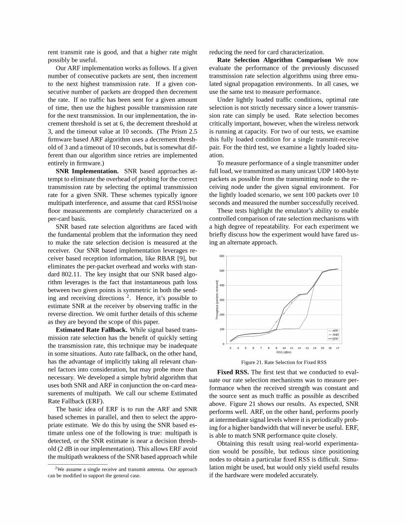
Fixed RSS.The first test that we conducted to eval-uate our rate selection mechanisms was to measure per-formance when the received strength was constant andthe source sent as much traffic as possible as describedabove. Figure 21 shows our results. As expected, SNRperforms well. ARF, on the other hand, performs poorlyat intermediate signal levels where it is periodically prob-ing for a higher bandwidth that will never be useful. ERF,is able to match SNR performance quite closely.
Obtaining this result using real-world experimenta-tion would be possible, but tedious since positioningnodes to obtain a particular fixed RSS is difficult. Simu-lation might be used, but would only yield useful resultsif the hardware were modeled accurately.

0
20
40
60
80
100
120
ARF SNR ERF
Thr
ough
put (
pack
ets)
Figure 22. Rate Selection for Under Multipath
Multipath. Next, we measured rate selection perfor-mance under in a multipath environment by commandingthe emulator to introduce a delayed copy of the primarysignal from the sender to the receiver (ideally this wouldbe both directions) with a fixed delay of 1 symbol pe-riod. With the RSS of the primary ray set to -77 dBm,we set the delayed ray strength to -84 dBm. As shown inFigure 22, ERF and ARF perform much better than SNRsince SNR sends at 11 Mbps. This also masks the factthat SNR uses multiple retries to even attain this through-put. This test demonstrates that multipath can cause theSNR based scheme to fail, although it is unclear whetherthis situation is common enough to worry about in manyenvironments. Nevertheless, ERF is able to use hardwareinformation to eliminate even this situation.
Eliciting this result using real-world experimentationwould essentially require a highly controlled large-scaleRF test range. Using simulation would simply not befeasible.
0
100
200
300
400
500
600
1 2 3 4 5 6 7 8 9 10 11 12 13 14 15 16 17 18 19 20 21
Time (seconds)
Th
rou
gh
pu
t (p
acke
ts)
ARFSNRERF
Figure 23. Rate Selection for Driveby Emulation
Fast Fading. We next tested performance in a fastfading environment, by measuring throughput during areplay of a “drive by” scenario similar to that shownin Figure 8. (In this experiment, we are simply emu-lating the fast fading caused by multipath, and are notactually emulating multiple signal copies. Hence, themultipath differences in the various algorithms are notdemonstrated by this experiment.) Figure 23 shows thatin this scenario, all algorithms perform similarly thoughARF and ERF generally outperform SNR when the sig-nal is marginal, while SNR and ERF generally outper-
form ARF when the signal is strong.This experiment demonstrates the benefits of being
able to replay the exact same signal trace. Comparingthese rate selection algorithms in a real drive-by exper-iment would be difficult since even slight variations inmobility would cause channel inconsistency across ex-periments. Hence, it would be difficult to separate theeffects on performance due to the different algorithmsfrom the effects due to RF channel variation.
In practice, experiments that include mobility are alsovery cumbersome to execute in the real-world especiallyas the number of mobile nodes increases.
A simulated test would result in a much coarsergrained use of the signal fading trace and fail to simu-late the effects of rapid fading due to vehicle mobility.Hence, confidence in the accuracy of such a simulatedtest would be greatly reduced.
7 Related Work7.1 Wireless Simulators
For several years now, ns-2 [10] has been the de factostandard means of experimental evaluation for the wire-less networking community. Yet ns-2’s wireless sup-port has not kept pace with current technology, andis targeted towards the original 802.11 standard devel-oped in 1997. Even this support, however, is inexactas ns-2 does not support automatic rate selection, uses anon-standard preamble, and a non-standard 802.11 ACKtimeout value. In addition, ns-2’s physical layer is partic-ularly simple [1]. As a result, some researchers are opt-ing to use commercial simulators such as QualNet [11]and OpNet [12] since they claim better support for cur-rent standards. Despite these claims, however, it is un-clear how well these simulators reflect actual hardware.
7.2 Wireless EmulatorsEmulation has proven to be a useful technique in
wired networking research [3, 13, 14], and it has an evenlarger potential in the wireless domain.
A common approach that has been taken for wire-less emulation [15, 16, 17] is to capture the behavior ofa wireless network in terms of parameters such as ca-pacity and error rates and then use a wired network toemulate this behavior. This has the advantage of allow-ing the use of real endpoints running real applications inreal time. The wireless MAC and physical layers, how-ever, are only very crudely simulated. For this reason, itis unclear whether or not this approach can obtain morerealistic results than pure simulation.
RAMON [18] uses three programmable attenuators toallow emulation of the signals between a single mobilenode and two base stations. While useful for the intendedapplication of mobile IP roaming investigation, the in-ability to independently control all signal paths severelylimits this approach.

7.3 Wireless TestbedsMore recently, several efforts such as Emulab [19],
WHYNET [20], Orbit [21], and MiNT [22] have begunusing controlled wireless testbeds. Though they mitigatesome of the issues with respect to control and isolation,these approaches still inherit the benefits and shortcom-ings of testbeds discussed in Section 1. In contrast, ourapproach allows for much finer grained and repeatablecontrol of the physical layer.
7.4 Channel Emulators / Fading SimulatorsThe most functionally similar approach to the wireless
emulator that we are developing is provided by commer-cial channel emulators [23, 24]. The goal of these emula-tors, however, is quite different. Rather than supportingemulation of all channels in a wireless network, com-mercial channel emulators are designed to support veryfine-grained emulation of the wireless channel betweeneither a pair of devices or between a small number ofbase stations and a small number of mobile devices (withthe total of both typically being less than 8). In addition,these emulators lack direct support for half-duplex nodesand require external components to support half-duplexnodes. As a result, while these emulators are very usefulfor equipment vendors evaluating a new device, the lim-ited scale, lack of support for complete interaction be-tween all nodes, and high cost make commercial channelemulators an unattractive option.
8 ConclusionUnderstanding and improving wireless network and ap-plication performance is increasingly important. Unfor-tunately, repeatable experimentation with real wirelessnodes running real applictions operating in a physical en-vironment is not feasible. For this reason, most wirelessresearch has relied on evaluation via simulation. Wire-less simulators do not, however, completely duplicatereal hardware in an operational environment, and the cor-rectness of wireless simulation is difficult to validate.
We have addressed these obstacles by developinga physically accurate wireless emulator that supportsreal applications running on real wireless devices. Wehave shown that this approach allows us to achieve finegrained control over RF propagation. We have demon-strated that this enables the analysis of higher layer per-formance in real networks and facilitates the develop-ment and evaluation of enhanced wireless protocols.
References
[1] M. Takai and J. Martin. Effects of Wireless Physical Layer Mod-eling in Mobile Ad Hoc Networks. Proc. of MobiHOC 2001.Long Beach, CA, October 2001.
[2] L. Peterson, T. Anderson, D. Culler, and T. Roscoe. A blueprintfor introducing disruptive technology into the internet.Proc. ofHotNets-I, October 2002.
[3] B. White, J. Lepreau, L. Stoller, R. Ricci, S. Guruprasad,M. Newbold, M. Hibler, C. Barb, and A. Joglekar. An integratedexperimental environment for distributed systems and networks.Proc. of OSDI 2002, December 2002.
[4] G. Judd and P. Steenkiste. Repeatable and Realistic Wireless Ex-perimentation through Physical Emulation.Proc. of HotNets-II.Cambridge, MA, November 2003.
[5] D. Aguayo, J. Bicket, S. Biswas, G. Judd, and R. Morris. Link-level Measurements from an 802.11b Mesh Network.Proc. ofSIGCOMM 2004. Portland, OR, August 2004.
[6] R. Punnoose, P. Nikitin, J. Broch, and D. Stancil. “optimizingwireless network protocols using real-time predictive propagationmodeling”. Proc. of the Radio and Wireless Conference (RAW-CON) 1999, August 1999.
[7] SmartAnt Telecomm Ltd. Yagi antennas,http://www.smartant.com/Products/ISM/2.4G/FYW24-01518BFL.pdf .
[8] P. Bahl, V. N. Padmanabhan, and A. Balachandran. A soft-ware system for locating mobile users: Design, evaluation, andlessons. Tech. Rep. MSR-TR-2000-12, Microsoft Corporation,February 2000.
[9] G. Holland, N. Vaidya, and P. Bahl. A Rate-Adaptive MAC Pro-tocol for Multi-hop Wireless Networks.Proceedings of Mobi-Com2001. Rome, Italy, September 2001.
[10] S. McCanne and S. Floyd. UCB/LBNL/VINT Network Simu-lator - ns (version 2), April 1999,http://www.isi.edu/nsnam/ns/ .
[11] Scalable Network Tech. Qualnet,http://www.scalable-networks.com/ .
[12] OPNET Tech. Opnet,http://www.opnet.com .[13] K. Fall. Network emulation in the vint/ns simulator.Proc. of
The Fourth IEEE Symposium on Computers and Communica-tions, July 1999.
[14] A. Vahdat, K. Yocum, K. Walsh, P. Mahadevan, D. Kostic,J. Chase, and D. Becker. “scalability and accuracy in a large-scale network emulator”.Proc. of OSDI 2002, Dec. 2002.
[15] B. Noble, M. Satyanarayanan, G. Nguyen, and R. Katz. Trace-based mobile network emulation.Proc. of SIGCOMM 1997, Sep-tember 1997.
[16] P. Mahadevan, K. Yocum, and A. Vahdat. Emulating large-scalewireless networks using modelnet.Poster and Abstract Mobicom2002, September 2002.
[17] T. Lin, S. Midkiff, and J. Park. A dynamic topology switchfor the emulation of wireless mobile ad hoc networks.Proc. ofthe 27th Annual IEEE Conference on Local Computer Networks(LCN’02), November 2002.
[18] E. Hernandez and S. Helal. “ramon: Rapid mobility network em-ulator”. Proc. of the 27th IEEE Conference on Local ComputerNetworks (LCN’02), November 2002.
[19] B. White, J. Lepreau, and S. Guruprasad. Lowering the barrier towireless and mobile experimentation.Proc. of HotNets-I, Octo-ber 2002.
[20] WHYNET. Whynet, http://chenyen.cs.ucla.edu/projects/whynet/ .
[21] D. Raychaudhuri, I. Seskar, M. Ott, S. Ganu, K. Ramachandran,H. Kremo, R. Siracusa, H. Liu, and M. Singh. Overview of theORBIT Radio Grid Testbed for Evaluation of Next-GenerationWireless Network Protocols.Proc. of WCNC 2005. New Orleans,LA, March 2005.
[22] S. S. P. De, A. Raniwala and T. Chiueh. MiNT: A MiniatuirizedNetwork Testbed for Mobile Wireless Research.Proc. of Infocom2005. Miami, FL, March 2005.
[23] PROPSim. Propsim c8 wideband multichannel simulator,http://www.propsim.net/ .
[24] Spirent Communications. Tas4500 flex5 rf channel emulator,http://www.spirent-communications.com/ .