Embed Size (px)
Citation preview
0
Using CDMA as Anti-Collision Methodfor RFID - Research & Applications
Andreas LoefflerFriedrich-Alexander-University of Erlangen-Nuremberg
Germany
1. Introduction
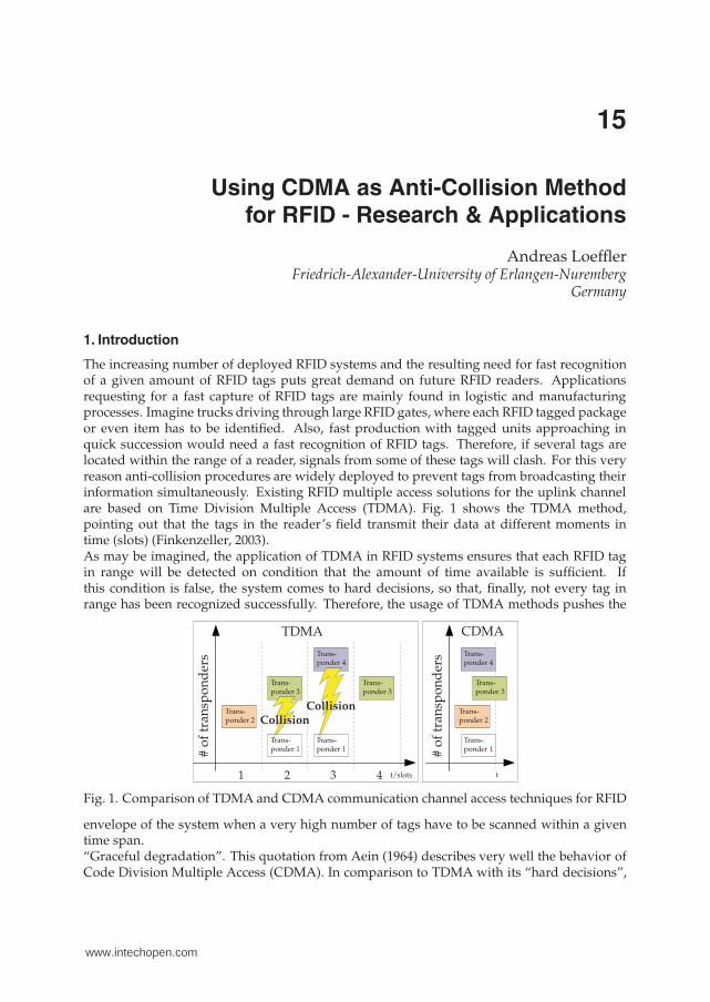
The increasing number of deployed RFID systems and the resulting need for fast recognitionof a given amount of RFID tags puts great demand on future RFID readers. Applicationsrequesting for a fast capture of RFID tags are mainly found in logistic and manufacturingprocesses. Imagine trucks driving through large RFID gates, where each RFID tagged packageor even item has to be identified. Also, fast production with tagged units approaching inquick succession would need a fast recognition of RFID tags. Therefore, if several tags arelocated within the range of a reader, signals from some of these tags will clash. For this veryreason anti-collision procedures are widely deployed to prevent tags from broadcasting theirinformation simultaneously. Existing RFID multiple access solutions for the uplink channelare based on Time Division Multiple Access (TDMA). Fig. 1 shows the TDMA method,pointing out that the tags in the reader’s field transmit their data at different moments intime (slots) (Finkenzeller, 2003).As may be imagined, the application of TDMA in RFID systems ensures that each RFID tagin range will be detected on condition that the amount of time available is sufficient. Ifthis condition is false, the system comes to hard decisions, so that, finally, not every tag inrange has been recognized successfully. Therefore, the usage of TDMA methods pushes the
TDMA CDMA
Trans-ponder 1
Trans-ponder 1
Trans-ponder 1
Trans-ponder 2
Trans-ponder 2
Trans-ponder 3
Trans-ponder 3
Trans-ponder 3
Trans-ponder 4
Trans-ponder 4
#o
ftr
ansp
on
der
s
#o
ftr
ansp
on
der
s
t/slots t1 2 3 4
CollisionCollision
Fig. 1. Comparison of TDMA and CDMA communication channel access techniques for RFID
envelope of the system when a very high number of tags have to be scanned within a giventime span.“Graceful degradation”. This quotation from Aein (1964) describes very well the behavior ofCode Division Multiple Access (CDMA). In comparison to TDMA with its “hard decisions”,
15
www.intechopen.com

2 Will-be-set-by-IN-TECH
CDMA-based systems take “soft decisions”, which means, that within the system eachadditionally introduced RFID tag decreases the overall probability of detection of all tags.However, for a particular amount of tags, the system may be optimized in such a way thatthe time needed for detection may be minimized. Therefore, for an RFID system underthose certain circumstances, the introduction of CDMA may offer a way out (Fig. 1). Thetransponders, each equipped with a unique quasi-orthogonal spreading code (e.g., Goldcodes (Gold, 1967a)), may use the radio channel whenever the transponders are ready totransmit their data (asynchronous CDMA). The objective is the realization of a DS (directsequence)-CDMA-based RFID system using semi-passive UHF transponders, with the readerproviding the recognition of multiple transponders simultaneously. This means that thetransponders are transmitting data within the same time range and frequency band, incontrast to the existing systems based on TDMA.The realized UHF transponders operate in semi-passive mode, meaning that the digital partof the transponder, i.e., the data generation, has an active power supply, whereas the highfrequency (HF) part works in passive mode taking advantage of the backscatter principle.The attendant RFID reader, though, is separated into two parts. Part one, described astransmitting system, generates a carrier wave at around 867 MHz. Part two, the receivingsystem, mainly demodulates the incoming backscattered signals of the RFID tags.This chapter is organized in seven sections. The first section gives a brief introduction tothe topic of anti-collision in UHF-RFID-based systems. The following sections introduceCDMA by outlining the advantages over the current used TDMA schemes. After introducingparticular problems backscattering RFID systems have to deal with, a concept and animplementation of such a CDMA-based RFID system is shown. The chapter ends with variousmeasurements concerning the system and subsequent results.
2. Anti-collision: EPC class 1 Gen 2
This section outlines some basic issues regarding anti-collision methods within RFID. Basicand state-of-the-art anti-collision methods are shown in Subsection 2.1. Subsection 2.2presents theoretical performance issues regarding the throughput by comparingstate-of-the-art TDMA methods with CDMA anti-collision methods.
2.1 ALOHA and slotted ALOHA
Before elucidating the state-of-the-art anti-collision method for UHF RFID systems, theprinciple of ALOHA and unslotted ALOHA (Bertsekas & Gallager, 1992) is illustrated, as theprinciple of ALOHA provides the basis for the modern anti-collision protocols. The ALOHAprotocol (or pure ALOHA), first published by Abramson (1970), is a very simple transmissionprotocol. The transmitter sends its data, no matter if the transmission channel is free ornot. This means the transmitter does not care about collisions with other transmitters. Thetransmitter resends its data later, if the acknowledgment from the receiver is missing. RFIDsystems based on the principle of pure ALOHA are, e.g., based on the TTF principle, i.e.,transponder-talks-first. The IPX protocol from IPICO (2009) is an example for RFID systemsusing unslotted or pure ALOHA.An extension of the ALOHA protocol, called slotted ALOHA (Roberts, 1975) introduces timeslots in which the transmitter must send its data at the beginning. Therefore, collisionsonly occur within a full time slot. This extension doubles the maximum throughput of thesystem. Most current RFID protocols are based on the principle of slotted ALOHA, as isalso the very commonly used EPC standard UHF Class-1 Generation-2 air interface protocol
306 Current Trends and Challenges in RFID
www.intechopen.com
Using CDMA as Anti-Collision Method
for RFID - Research & Applications 3
V1.2.0 (ISO 18000-6C), commonly known as “Gen2”. Basically, the “Gen2” standard defines,that every communication is triggered by the RFID reader, i.e., RTF (reader-talks-first). Aninventory round, i.e., the process of detecting all available transponders, is started with theQuery-command to acquire all transponders available in the read range. This commandinherits a so called Q-parameter. Using this Q-parameter, every transponder generates arandom number RN in the range [0; 2Q − 1] and initializes its internal slot counter withthis random number. If, at a given moment, the value of the slot counter of one or moretransponders equals 0, the transponders send a 16 bit random number called RN16. Afterthe acknowledgment of the RN16 through the reader, the electronic product code (EPC)is transmitted from the transponder to the reader and the transponder will be marked asinventoried. All the left-over (non-marked) transponders are prompted to decrement its slotcounter by sending a QueryRep-command, and the procedure starts all over again. In the caseof several transponders initializing their slot counters with the same random number RN, itwill come sooner or later to a signal collision as the slot counters will reach zero at the sametime slot. If the reader recognizes such a collision, another inventory round will be initiatedto identify the left-over transponders. Therefore, a newly value of Q will be introduced andnew random numbers will be calculated. To sum up, one could say that the choice of Q is atypical trade-off. Choosing a high Q will lead to a smaller number of collisions, at the expenseof an increasing time needed for an inventory round. Indeed, a smaller Q will lead to lessacquisition time, but to more collisions.Plenty of work has been done to improve the current EPC standard. Improving the currentstandard anti-collision method by choosing an appropriate value of Q, e.g., dynamically, isdescribed in Maguire & Pappu (2009); Pupunwiwat & Stantic (2010); Wang & Liu (2006). Theright choice of Q is of great importance for the overall system performance, so that an accurateestimation would improve the time needed for an inventory round. Slightly new algorithms,based on the current EPC “Gen2” standard are outlined, e.g, in Cui & Zhao (2009); Lee et al.(2008). New better performing algorithms for the slotted ALOHA protocol for RFID aredescribed in Bang et al. (2009); Choi et al. (2007); Liu et al. (2009); Makwimanloy et al. (2009).A complete new system with time hopping on the communication link from tag to reader isoutlined in Zhang et al. (2010).
2.2 Comparison: CDMA versus TDMA in UHF-RFID
The throughput S in dependence of the traffic channel rate G describes the performance ofa given transmission system regarding how many packets must be transmitted (statistically)
until a successful transmission occurs. This statement is given with the term GS as described
by Kleinrock & Tobagi (1975). The reciprocal of this term, i.e., SG defines accordingly the
probability of a successful transmission. The channel capacity is determined by maximizing Swith respect to G (Kleinrock & Tobagi, 1975). According to Abramson (1970) the pure ALOHAtransmission has a relation between S and G of
S = G e−G (1)
, whereas the throughput of the slotted ALOHA transmission is defined after Roberts (1975)with
S = G e−2G (2)
. Accordingly, the maximum channel capacity is 12e ≈ 18.4% for pure ALOHA and 1
e ≈ 36.8%for slotted ALOHA.For a fair comparison between CDMA-based systems and ALOHA systems, the total
307Using CDMA as Anti-Collision Method for RFID - Research & Applications
www.intechopen.com
4 Will-be-set-by-IN-TECH
Traffic rate G
Th
rou
gh
pu
tS
ALOHAslotted ALOHACDMA (C = 1)CDMA (C = 5)CDMA (C = 10)
0 .5 .73 1 1.5 2 2.5 3 3.5 40
.1
.184
.3
.368.4
.5
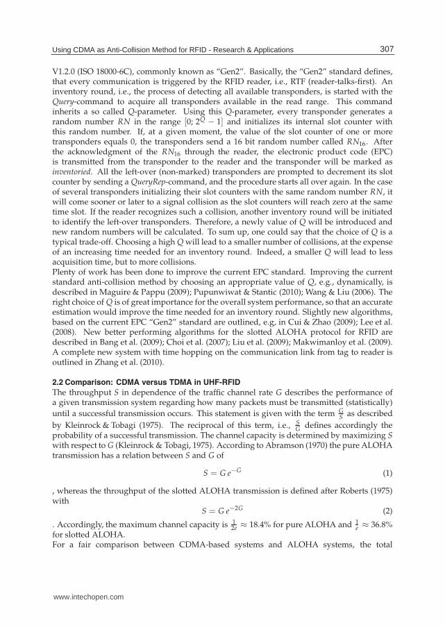
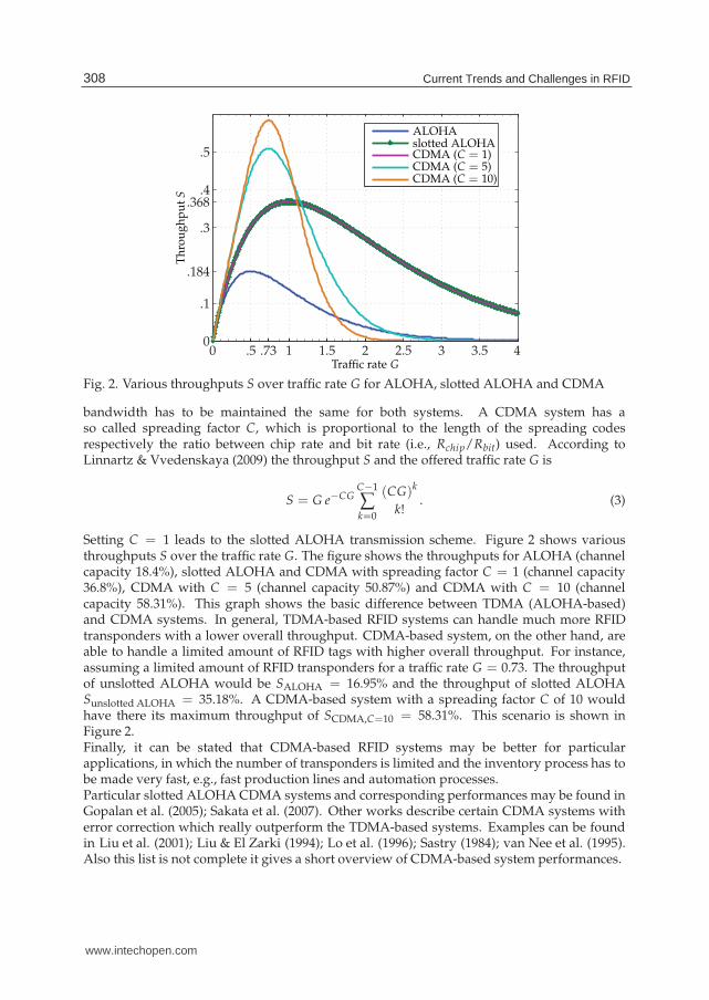
Fig. 2. Various throughputs S over traffic rate G for ALOHA, slotted ALOHA and CDMA
bandwidth has to be maintained the same for both systems. A CDMA system has aso called spreading factor C, which is proportional to the length of the spreading codesrespectively the ratio between chip rate and bit rate (i.e., Rchip/Rbit) used. According toLinnartz & Vvedenskaya (2009) the throughput S and the offered traffic rate G is
S = G e−CGC−1
∑k=0
(CG)k
k!. (3)
Setting C = 1 leads to the slotted ALOHA transmission scheme. Figure 2 shows variousthroughputs S over the traffic rate G. The figure shows the throughputs for ALOHA (channelcapacity 18.4%), slotted ALOHA and CDMA with spreading factor C = 1 (channel capacity36.8%), CDMA with C = 5 (channel capacity 50.87%) and CDMA with C = 10 (channelcapacity 58.31%). This graph shows the basic difference between TDMA (ALOHA-based)and CDMA systems. In general, TDMA-based RFID systems can handle much more RFIDtransponders with a lower overall throughput. CDMA-based system, on the other hand, areable to handle a limited amount of RFID tags with higher overall throughput. For instance,assuming a limited amount of RFID transponders for a traffic rate G = 0.73. The throughputof unslotted ALOHA would be SALOHA = 16.95% and the throughput of slotted ALOHASunslotted ALOHA = 35.18%. A CDMA-based system with a spreading factor C of 10 wouldhave there its maximum throughput of SCDMA,C=10 = 58.31%. This scenario is shown inFigure 2.Finally, it can be stated that CDMA-based RFID systems may be better for particularapplications, in which the number of transponders is limited and the inventory process has tobe made very fast, e.g., fast production lines and automation processes.Particular slotted ALOHA CDMA systems and corresponding performances may be found inGopalan et al. (2005); Sakata et al. (2007). Other works describe certain CDMA systems witherror correction which really outperform the TDMA-based systems. Examples can be foundin Liu et al. (2001); Liu & El Zarki (1994); Lo et al. (1996); Sastry (1984); van Nee et al. (1995).Also this list is not complete it gives a short overview of CDMA-based system performances.
308 Current Trends and Challenges in RFID
www.intechopen.com
Using CDMA as Anti-Collision Method
for RFID - Research & Applications 5
TX path
Control
RX path
TX
RX
Tag 1
Code 1
Tag 2
Code 2
Tag nCode n
RFID reader
Data
Data
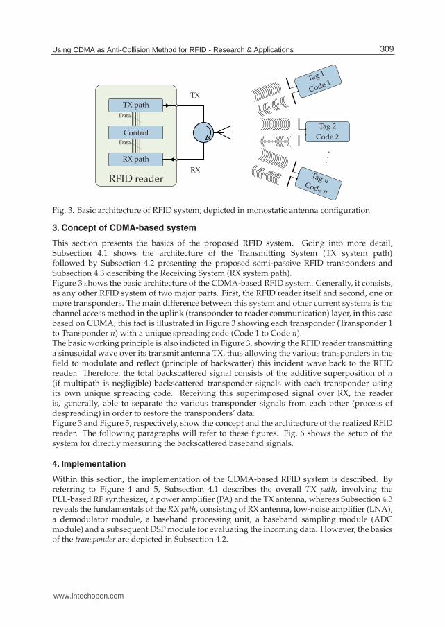
Fig. 3. Basic architecture of RFID system; depicted in monostatic antenna configuration
3. Concept of CDMA-based system
This section presents the basics of the proposed RFID system. Going into more detail,Subsection 4.1 shows the architecture of the Transmitting System (TX system path)followed by Subsection 4.2 presenting the proposed semi-passive RFID transponders andSubsection 4.3 describing the Receiving System (RX system path).Figure 3 shows the basic architecture of the CDMA-based RFID system. Generally, it consists,as any other RFID system of two major parts. First, the RFID reader itself and second, one ormore transponders. The main difference between this system and other current systems is thechannel access method in the uplink (transponder to reader communication) layer, in this casebased on CDMA; this fact is illustrated in Figure 3 showing each transponder (Transponder 1to Transponder n) with a unique spreading code (Code 1 to Code n).The basic working principle is also indicted in Figure 3, showing the RFID reader transmittinga sinusoidal wave over its transmit antenna TX, thus allowing the various transponders in thefield to modulate and reflect (principle of backscatter) this incident wave back to the RFIDreader. Therefore, the total backscattered signal consists of the additive superposition of n(if multipath is negligible) backscattered transponder signals with each transponder usingits own unique spreading code. Receiving this superimposed signal over RX, the readeris, generally, able to separate the various transponder signals from each other (process ofdespreading) in order to restore the transponders’ data.Figure 3 and Figure 5, respectively, show the concept and the architecture of the realized RFIDreader. The following paragraphs will refer to these figures. Fig. 6 shows the setup of thesystem for directly measuring the backscattered baseband signals.
4. Implementation
Within this section, the implementation of the CDMA-based RFID system is described. Byreferring to Figure 4 and 5, Subsection 4.1 describes the overall TX path, involving thePLL-based RF synthesizer, a power amplifier (PA) and the TX antenna, whereas Subsection 4.3reveals the fundamentals of the RX path, consisting of RX antenna, low-noise amplifier (LNA),a demodulator module, a baseband processing unit, a baseband sampling module (ADCmodule) and a subsequent DSP module for evaluating the incoming data. However, the basicsof the transponder are depicted in Subsection 4.2.
309Using CDMA as Anti-Collision Method for RFID - Research & Applications
www.intechopen.com

6 Will-be-set-by-IN-TECH
Computer
US
B
DSP
DSP module
UART
Microcontroller
Base module
SPI
PLL
RF synthesizer
PA
TX
ADC
ADC module
Analog basebandprocessingmodule
I
Q
Zero-IFDemodulator
Demodulator module
LNA
RX
✞
✝
☎
�RFID reader
Fig. 4. Basic concept of RFID reader; depicted in bistatic antenna configuration
4.1 TX system path
The proposed semi-passive UHF transponder works in accordance with the principle ofbackscattering. The incident wave to be backscattered is generated by the Transmitting System.Considering the RFID uplink channel (tag to reader), the introduced Transmitting System(see Figure 3 and Figure 5) consists of a PLL-based RF synthesizer (Figure 3 and Figure 5), generating a sine wave (here with fcarrier = 866.5 MHz, maximum output power Pout =1 dBm at 50 Ω), an upstream power amplifier (PA, Gain GPA = 20 dB, 1 dB compressionpoint = 24 dBm), and a linear polarized 50 Ω antenna (TX, Gain GTX ≈ 7 dBi). The purposeof the transmitter is to generate an RF wave to be reflected (backscattered) by the UHFtransponder whereby the reflected wave is received by the Receiving System further discussedin Subsection 4.3.It has to be mentioned that the RF synthesizer not only generates a sine wave for thetransmitting part, but also for the receiving part of the system. Indeed, it is used as localoscillator (LO) source for the downmixing part of the receiver. However, both synthesized RFwaves inherit the same frequency as they are both created by the same PLL; the waves onlydiffer in π in phase.
4.2 Transponder
The major tasks of the semi-passive UHF transponders are:
• Generate spreading code
• Create spreaded data
310 Current Trends and Challenges in RFID
www.intechopen.com
Using CDMA as Anti-Collision Method
for RFID - Research & Applications 7
Analog baseband processing module
DSP module
Base module
RF synthesizer
PA
TX
ADC module
Demodulator moduleLNA
RX
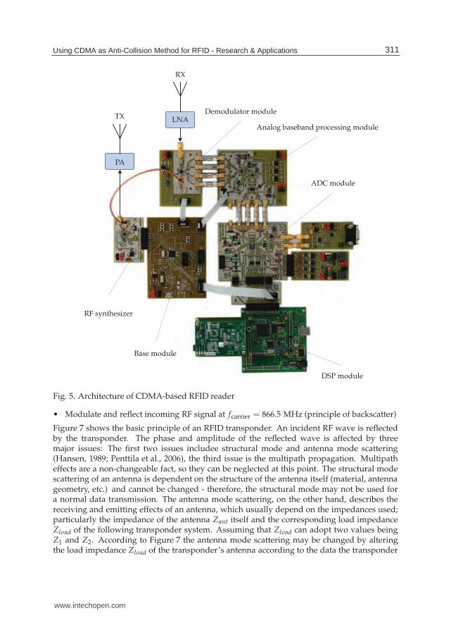
Fig. 5. Architecture of CDMA-based RFID reader
• Modulate and reflect incoming RF signal at fcarrier = 866.5 MHz (principle of backscatter)
Figure 7 shows the basic principle of an RFID transponder. An incident RF wave is reflectedby the transponder. The phase and amplitude of the reflected wave is affected by threemajor issues: The first two issues includee structural mode and antenna mode scattering(Hansen, 1989; Penttila et al., 2006), the third issue is the multipath propagation. Multipatheffects are a non-changeable fact, so they can be neglected at this point. The structural modescattering of an antenna is dependent on the structure of the antenna itself (material, antennageometry, etc.) and cannot be changed - therefore, the structural mode may not be used fora normal data transmission. The antenna mode scattering, on the other hand, describes thereceiving and emitting effects of an antenna, which usually depend on the impedances used;particularly the impedance of the antenna Zant itself and the corresponding load impedanceZload of the following transponder system. Assuming that Zload can adopt two values beingZ1 and Z2. According to Figure 7 the antenna mode scattering may be changed by alteringthe load impedance Zload of the transponder’s antenna according to the data the transponder
311Using CDMA as Anti-Collision Method for RFID - Research & Applications
www.intechopen.com
8 Will-be-set-by-IN-TECH
RFIDantenna TX
antenna
Modulator
µC
RFIDtag
RXantenna
RX in I, Q out
Demodulator +Baseband processor
LO in
TX source
LO source
LNA
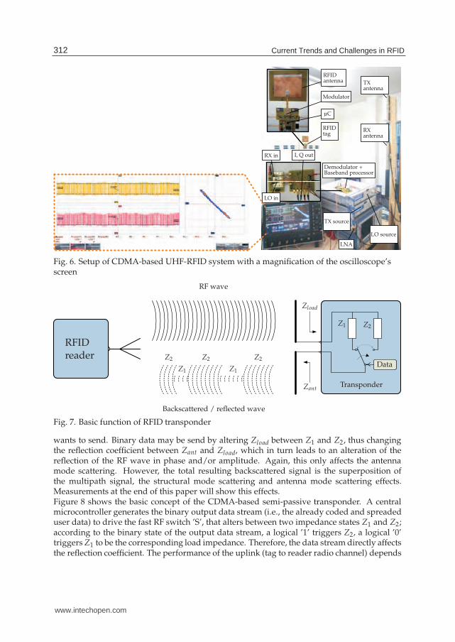
Fig. 6. Setup of CDMA-based UHF-RFID system with a magnification of the oscilloscope’sscreen
RF wave
Zant
Zload
Z1
Z1
Z1
Z2
Z2Z2Z2Data
Transponder
RFIDreader
Backscattered / reflected wave
Fig. 7. Basic function of RFID transponder
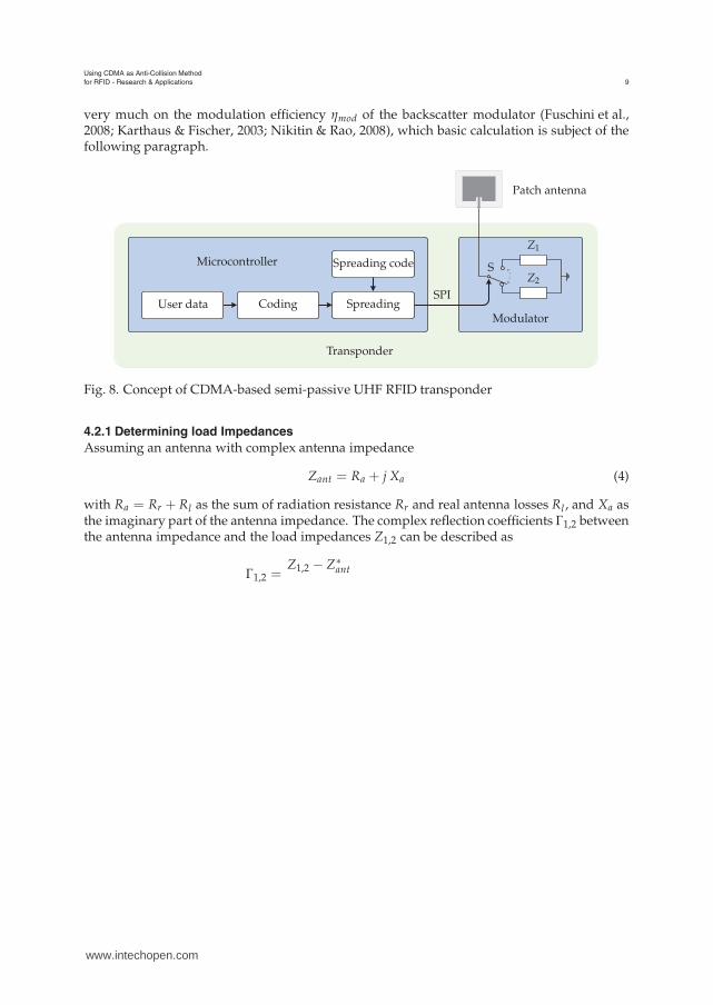
wants to send. Binary data may be send by altering Zload between Z1 and Z2, thus changingthe reflection coefficient between Zant and Zload, which in turn leads to an alteration of thereflection of the RF wave in phase and/or amplitude. Again, this only affects the antennamode scattering. However, the total resulting backscattered signal is the superposition ofthe multipath signal, the structural mode scattering and antenna mode scattering effects.Measurements at the end of this paper will show this effects.Figure 8 shows the basic concept of the CDMA-based semi-passive transponder. A centralmicrocontroller generates the binary output data stream (i.e., the already coded and spreadeduser data) to drive the fast RF switch ’S’, that alters between two impedance states Z1 and Z2;according to the binary state of the output data stream, a logical ’1’ triggers Z2, a logical ’0’triggers Z1 to be the corresponding load impedance. Therefore, the data stream directly affectsthe reflection coefficient. The performance of the uplink (tag to reader radio channel) depends
312 Current Trends and Challenges in RFID
www.intechopen.com
Using CDMA as Anti-Collision Method
for RFID - Research & Applications 9
very much on the modulation efficiency ηmod of the backscatter modulator (Fuschini et al.,2008; Karthaus & Fischer, 2003; Nikitin & Rao, 2008), which basic calculation is subject of thefollowing paragraph.
Microcontroller
Transponder
Modulator
Patch antenna
Z1
Z2
User data Coding
Spreading code
SpreadingSPI
S
Fig. 8. Concept of CDMA-based semi-passive UHF RFID transponder
4.2.1 Determining load Impedances
Assuming an antenna with complex antenna impedance
Zant = Ra + j Xa (4)
with Ra = Rr + Rl as the sum of radiation resistance Rr and real antenna losses Rl , and Xa asthe imaginary part of the antenna impedance. The complex reflection coefficients Γ1,2 betweenthe antenna impedance and the load impedances Z1,2 can be described as
Γ1,2 =Z1,2 − Z∗
ant
www.intechopen.com
10 Will-be-set-by-IN-TECH
with U0 as the antenna’s open circuit voltage and a being the wave from the antennaimpedance to the load impedance (see Rembold (2009) for details).Maximum modulation efficiency ηmod is achieved when the difference of the complexreflections coefficients Γ1 and Γ2 is maximum. Supposing two vectors (Γ1 and Γ2) in a complexcoordinate system, the maximum difference between both vectors is achieved at the pointwhen the phase ϕΓ differs with π under the assumption that the maximum absolute value ofany Γ is limited to 1. That determines the complex reflection coefficients Γ1,2 to
Γ1 = ejϕΓ,1 (9)
Γ2 = ejϕΓ,1+jπ (10)
Setting ϕΓ,1 to 0 sets Γ1,2 to ±1. According to Equation (5) this will define the load impedancesto
Z1,2 =Z∗
ant + Γ1,2 Zant
1 − Γ1,2(11)
→ Z1 =Z∗
ant + Zant
0= ±∞ (12)
→ Z2 =Z∗
ant − Zant
2=
−2jXa
2= −jXa (13)
The antenna designed for the RFID transponders is a 50 Ω patch antenna (Figure 10).Therefore the imaginary part (within the specified frequency range) Xa ≈ 0. This determinesZ2 = −jXa ≈ 0. A load impedance of Z1 = ∞ corresponds to an open circuit wheresZ2 = 0 corresponds to a short circuit. Choosing open and short circuit states as desired loadimpedances, the maximum achievable modulation efficiency is, according to Equation (7),determined to be
ηmod =2
π2|+1 + 1|2 =
8
π2≈ 81% (14)
In order to have the maximum modulation efficiency for the CDMA-based RFID system, theload impedances of the realized semi-passive transponders are set to open and short circuit.By choosing these values as load impedances, one has to keep in mind, that this is onlyadvisable for semi-passive UHF RFID transponders. If passive transponders are designed, onehas to consider the power consumption into its calculations. Therefore, open and short circuitvalues are not suitable, as the backscattered power is, in fact, too high, as the transponderneeds a large portion of the incoming power for supplying itself (Dobkin, 2008).
4.2.2 Transponder basics
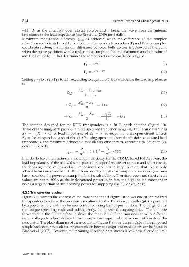
Figure 9 illustrates the concept of the transponder and Figure 10 shows one of the realizedtransponders to achieve the previously mentioned tasks. The microcontroller (µC) is poweredby a power supply and may be user-controlled using USB or pushbuttons. The µC generatesthe unique spreading code and subsequently, the spreaded outgoing data. The data areforwarded to the SPI interface to drive the modulator of the transponder with differentinput voltages to adjust different load impedances respectively reflection coefficients of themodulator. The block diagram of the modulator (Figure 8) shows the principle of the proposedsimple backscatter modulator. An example on how to design load modulators can be found inPardo et al. (2007). However, the incoming spreaded data stream is low-pass filtered to limit
314 Current Trends and Challenges in RFID
www.intechopen.com
Using CDMA as Anti-Collision Method
for RFID - Research & Applications 11
✞
✝
☎
�Transponder
µC
RSSI
Modulator
RF Divider
Measuring field strength
Backscattering data
Dividing RF frequency
Base board
Patch antenna
SPI
ADC
I/O
Tin
yp
atc
ha
nte
nn
aT
iny
pa
tch
an
ten
na
En
erg
ysu
pp
ly
Fig. 9. Block diagram of semi-passive UHF RFID transponder with limited downlinkcapabilities
the outgoing bandwidth. As the modulator should be as simple as possible, an RF switch ’S’forms the interface between the logic data and the backscattered HF wave. The inputs of theswitch are driven by the spreaded data stream with two voltage levels (0 and 2.75 V) given bya buffer driver. One connection of the switch is linked to the patch antenna’s microstrip line(50 Ω); the ground connection is linked to the patch antennas ground plane. By triggering theswitch’s input with the spreaded data to be sent, either Z1 or Z2 is connected to the antenna.This modification changes in turn the reflection of an incident electromagnetic wave. Thedifference of phase and amplitude of the reflection is a direct indicator for the efficiency ofa backscattering modulator. As mentioned above the modulators load impedances are set toopen and short circuit to achieve maximum modulation efficiency. An exemplary spectralextract of the backscattered output of the transponder, measured at the receiving antenna, isgiven in Figure 17. On closer inspection, one can see the spreaded data (chip rate is 1.5 Mcps)around the carrier frequency (866.5 MHz). As these data signal levels (P ≈ −90 dBm± 10 dB)are not very high, an accurate implementation of the receiving system becomes necessary.For a limited downlink (reader to tag) capability the transponders are equipped with a modulefor measuring the field strength (RSSI) and a module for measuring the frequency (RF Divider)of the incident RF wave emitted by the reader. The RF Divider is currently used to indicate thetransponder to send its data as soon as a carrier between 865 MHz and 868 MHz is detected.The RSSI module is used for statistical measurements. Anyway, both modules are not part ofthis work.
315Using CDMA as Anti-Collision Method for RFID - Research & Applications
www.intechopen.com

12 Will-be-set-by-IN-TECH
Modulator
RSSI
Base board
RF Divider
Patch antenna
Fig. 10. Prototype of semi-passive UHF RFID transponder
Z2, e.g., short circuit Z1, e.g., open circuit
RF switch Screening shield
Fig. 11. Backscatter modulator
4.2.3 Modulator
The transponder’s modulator is one of the key components of the system. Usually, it effectsthe energy supply (only for passive working transponders) and the modulation efficiency (forpassive and semi-passive working transponders) of transponders. Therefore, it has a directeffect for the maximum achievable range of such a system. The principle of the modulatorhas been already discussed above, so that this paragraph focuses primarily on the realization.Figure 11 shows the modulator, with and without RF shielding. The left part of the modulatoris connected to the transponder’s base board, the right SMA plug to the patch antenna asshown in Figure 10. The part within the RF shielding is responsible for the backscatteringeffects. A part of the incident RF wave is fed into the modulator. The part depends onthe antenna (structural and antenna mode) and the reflection coefficient between antenna
316 Current Trends and Challenges in RFID
www.intechopen.com
Using CDMA as Anti-Collision Method
for RFID - Research & Applications 13
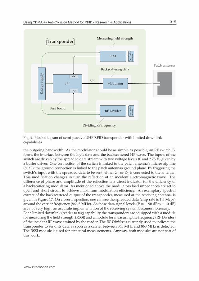
impedance Zant and the load impedance Zload of the connected modulator. This part is fedinto the RF switch and the load impedance (either Z1 or Z2), which corresponds to the currentstate of the switch. The state of the switch is defined by a buffered microcontroller output.which itself shows the current voltage of the binary data stream to be sent. In the case of Z1
(open circuit state), the incident wave is entirely reflected with no phase shift. State Z2 (shortcircuit) also corresponds to a total reflection, but with a phase shift of 180◦.Measuring the load impedances of the modulator show a very good accordance with thetheoretical results. Figure 12 shows the reflection coefficients within a Smith chart. As one cansee the phase difference is not exactly π. Z2 (short circuit) has nearly short circuit properties;Z2 (open circuit) has nearly open circuit properties. The frequency range of the measurementwas between 852 MHz and 882 MHz.
0 ∞0.2
0.5
1.0
2.0
5.0
0.2
0.5
1.0
2.0
5.0
0.2
0.5
1.0
2.0
5.0
✞
✝
☎
�
Shortcircuit
✞
✝
☎
�
Opencircuit
Fig. 12. Smith chart of modulator
4.2.4 Gold codes
The choice of an appropriate set of spreading codes is a key issue when designing CDMAsystems. Gold codes seem to be one of the best codes to be used in UHF RFID systems.Mutti & Floerkemeier (2008), for instance, state that Gold codes outperform Kasami codes.Moreover, one Gold code family contains a large number of unique codes, which provides ahigh probability of finding a well-suited set of codes for a system to be designed.Gold codes, first introduced by Robert Gold (Gold, 1967b), are commonly used in spreadspectrum systems, such as WLAN and UMTS as well as in GPS (C/A code). The generationof Gold codes is quite simple as only two linear feedback shift registers (LFSR) are necessaryto create one set of codes. Other advantages of Gold code are:
• Good balance between auto- and cross-correlation
• Flexibility in code length
• No user synchronization necessary, i.e. the transponders need not to be synchronizedamong each other
Because of above mentioned advantages, the proposed CDMA-based system uses Goldsequences.
317Using CDMA as Anti-Collision Method for RFID - Research & Applications
www.intechopen.com

14 Will-be-set-by-IN-TECH
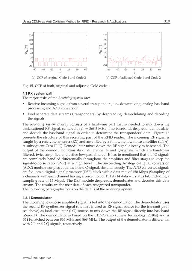
However, Gold codes have a length of 2m − 1 with m being the order of each linear feedbackshift register. For reasons of flexibility a Gold code generator has been implemented onthe transponder’s 32 bit µC. The choice fell upon a Gold code length of 127 (m = 7). Thecharacteristic polynomial is 137dec for the first LFSR and 143dec for the second one. Theinitial value for the first LFSR is 85dec. By choosing two Gold codes (Code 1 and Code 2)the second LFSR is initialized with 127dec for the first and with 111dec for the second code.Then, a small adjustment was made to the generated Gold codes to be more compatible to theµC. A succeeding binary ’0’ is added to each code to move it to a length of 128 bit. To showthe effect of this ’0’, the auto-correlation function (ACF) and cross-correlation function (CCF)have been evaluated for both Codes. Figure 13 shows the ACF Φcc of the original 127 bit Goldcodes. Figure 14 illustrates the ACF Φcc(τ) of the adjusted (127+1 bit) Gold codes. The resultsare slightly higher values beyond the peak value at τ = 0. As not only the auto-correlationcounts, the corresponding cross-correlation Φ12
(τ) between the two codes are presented inFigure 15. As expected the values of the adjusted codes are slightly higher compared to theoriginal ones, but without loosing the typical noise-like character. This means, that the effect ofthe added ’0’ is negligible for further considerations. However, final system implementationshave to consider that fact.
τ
Φ11(τ)
-60 -40 -20 0 20 40 60-20
0
20
40
60
80
100
120
(a) ACF of Code 1
τ
Φ22(τ)
-60 -40 -20 0 20 40 60-20
0
20
40
60
80
100
120
(b) ACF of Code 2
Fig. 13. ACF of original Gold codes
τ
Φ11(τ)
-60 -40 -20 0 20 40 60
-20
0
20
40
60
80
100
120
(a) ACF of Code 1
τ
Φ22(τ)
-60 -40 -20 0 20 40 60
-20
0
20
40
60
80
100
120
(b) ACF of Code 2
Fig. 14. ACF of adjusted Gold codes
318 Current Trends and Challenges in RFID
www.intechopen.com
Using CDMA as Anti-Collision Method
for RFID - Research & Applications 15
τ
Φ12(τ)
-60 -40 -20 0 20 40 60-20
0
20
40
60
80
100
120
(a) CCF of original Code 1 and Code 2
τ
Φ12(τ)
-60 -40 -20 0 20 40 60
-20
0
20
40
60
80
100
120
(b) CCF of adjusted Code 1 and Code 2
Fig. 15. CCF of both, original and adjusted Gold codes
4.3 RX system path
The major tasks of the Receiving system are:
• Receive incoming signals from several transponders, i.e., downmixing, analog basebandprocessing and A/D conversion
• Find separate data streams (transponders) by despreading, demodulating and decodingthe signals
The Receiving system mainly consists of a hardware part that is needed to mix down thebackscattered RF signal, centered at fc = 866.5 MHz, into baseband, despread, demodulate,and decode the baseband signal in order to determine the transponders’ data. Figure 16presents the structure of this receiving part of the RFID reader. The incoming RF signal iscaught by a receiving antenna (RX) and amplified by a following low noise amplifier (LNA).A subsequent Zero-IF IQ-Demodulator mixes down the RF signal directly to baseband. Theoutput of the demodulator consists of differential I- and Q-signals, which are band-passfiltered, twice amplified and active low-pass filtered. It has to mentioned that the IQ signalsare completely handled differentially throughout the amplifier and filter stages to keep thesignal-to-noise ratio (SNR) at a high level. The succeeding Analog-to-Digital conversion(ADC) module samples both, the I- and Q-signal, simultaneously. The A/D converted signalsare fed into a digital signal processor (DSP) block with a data rate of 450 Mbps (Sampling of2 channels with each channel having a resolution of 15 bit (14 data + 1 status bit) including asampling rate of 15 Msps). The DSP module despreads, demodulates and decodes this datastream. The results are the user data of each recognized transponder.The following paragraphs focus on the details of the receiving system.
4.3.1 Demodulator
The incoming low-noise amplified signal is fed into the demodulator. The demodulator usesthe second RF synthesizer signal (the first is used as RF signal source for the transmit path,see above) as local oscillator (LO) source, to mix down the RF signal directly into baseband(Zero-IF). The demodulator is based on the LT5575 chip (Linear Technology, 2010a) and is50 Ω-matched between 865 MHz and 868 MHz. The output of the demodulator is differentialwith 2 I- and 2 Q-signals, respectively.
319Using CDMA as Anti-Collision Method for RFID - Research & Applications
www.intechopen.com

16 Will-be-set-by-IN-TECH
RX
LNA
Zero-IF Demodulator Band-pass filter Amplifier Amplifier Active low-pass filter ADC module DSP
DSP
Clock generator
Mu
ltip
lexe
r
PD
AP
3xPLL3xVCO
Vre f
PLLVCO
I
Q
0◦
90◦
14
14
14
14
f-D
iv.
ADC
ADC
Fig. 16. Architecture of receiving system
4.3.2 Band-pass filter
The differential working band-pass filter, which succeeds the demodulator, is used tosuppress the DC-part of the baseband signal, i.e. mainly the non-information carryingdown-mixed carrier signal, and high-frequency disturbing signals (from the internal mixerof the demodulator). Therefore the passband is set between 16 kHz and 20 MHz.
4.3.3 Amplifier stage
The following amplifier stage is build upon two differential amplifiers (LTC6421-20(Linear Technology, 2010d) and LTC6420-20 (Linear Technology, 2010c)), each with adifferential voltage gain of 10 V/V.
4.3.4 Active anti-aliasing filter
The last analog signal processing stage is an active anti-aliasing filter for the succeeding ADCmodule. The cut-off frequency of the 4th order low-pass filter (Chebyshev characteristic) iscurrently set to 2.5 MHz. This stage is based on an LT6604-2.5 (Linear Technology, 2010b).
4.3.5 A/D conversion
One very important part of the receiving system is a well-designed A/D conversion stagefor the baseband signal. The subjective of the ADC module is a time synchron samplingof the differential I- and Q-signals. The module is based on a dual A/D converter of typeAD9248 from Analog Devices (2010a). Two channels may be sampled synchronously with aresolution of 14 bit per channel. Maximum sampling rate is 40 Msps. As the fast parallel inputof the succeeding DSP module has only 20 bit the internal multiplexer of the A/D converteris used to transmit the I- and Q-data after each other. Therefore one status bit is used toindicate the current transmitted channel data. Here, the A/D converter is driven with 15Msps per channel, which corresponds to an overall sampling clock rate of 30 MHz. The 14 bitper channel plus the status bit and the sampling rate, generate in total a data rate of 450 Mbpsto be handled by the subsequent DSP module.
4.3.6 DSP module
The purpose of the DSP is the handling of all calculations, necessary to evaluate thetransponders’ user data. Therefore, the following stages are necessary:
• Data acquisition (from ADC module)
• Despreading of baseband signals
• Demodulation of despreaded signals
• Decoding of demodulated data
320 Current Trends and Challenges in RFID
www.intechopen.com

Using CDMA as Anti-Collision Method
for RFID - Research & Applications 17
The following paragraphs give a short introduction to these topics. The data acquisition phasehas to be accomplished only once, against what the following stages have to be passed throughby every transponder respectively spreading code available.
4.3.6.1 Data acquisition
As the amount of data to handle is quit large (450 Mbps) the data streams are not handled inreal time. However, through the usage of this DSP (ADSP-21469 from Analog Devices (2010b))the processing speed is quite high. The A/D converted data signals are acquired through theDSP’s PDAP (Parallel Data Aquisition Port) interface. From there, they are transfered to aninternal 8x32 bit buffer. Finally, the data are passed via DMA access to an internal memory.As of limited memory capabilities the data is transferred block-wise to the external memory.As the sampled values are stored as 32 bit values (DWORD), the amount of data for one shot(duration is Tshot ≈ 188 µs) is 90112 samples per channel, so in total 720896 bytes or 704 kbytes.
4.3.6.2 Despreading
The process of despreading is the most calculation intensive operation the DSP has to handle.As this phase needs more time than the data acquisition process the system is, up-to-date notable to work real-time. Parallel processing would be a good solution. The DSP itself has aclock rate of 450 MHz.Despreading data from the baseband signal has to be done for I- and Q-channel separately.The despreading operation is realized using the cross-correlation between I and Q signalsand the origin codes used by every transponder in the field. If s[k] is the I or Q signaland c[k] one of the corresponding codes of one of the transponders, the cross-correlationΦs,c(τ) between these signals is done by multiplying every time instance signal s with code c.Equation (15) shows the corresponding relationship between c[k] and s[k], whereas ⋆ matchesthe convolution function:
[s⋆ c][τ] = Φs,c(τ) =+∞
∑t=−∞
s∗[t] · c[τ + t] (15)
A code length of 128 chips corresponds to 1280 samples (Rchip = 1.5 Msps and Rsample =15 Msps) and 90112 samples per channel for I and Q. This results into 230,686,720multiplications and 180,224 additions.One goal was to reduce this high amount of operations. This is realized through estimationof the time moments the chips appear within the IQ signals. This estimation method worksas follows. The IQ baseband signal is sampled and correlated among the first 2 · 1280 = 2560samples. This results in 6,553,600 multiplications and 5120 additions. The first maximum,corresponding to the first peak indicates the initial index i0 to start the despreading process.The following peaks are estimated by jumping from i0, 1280 samples ahead. As certainincertitudes (oscillators, etc.) will lead to synchronization errors, the correlation is not onlymade at sample index i0 + n · 1280, but at 5 samples before and after the estimated time index.That means, the second peak is determined by executing the cross-correlation Φi,1(τ) as givenin Equation (16).
Φi,1(τ) =i0+1280+5
∑t=i0+1280−5
s∗[t] · c[τ + t] (16)
The result is 11 correlations per peak and a new synchronization index, as the new peakindicates the next starting point for the succeeding peak estimation. With 70 data peakswithin one shot and 1 within the initial guess, the total number of correlations per channel
321Using CDMA as Anti-Collision Method for RFID - Research & Applications
www.intechopen.com
18 Will-be-set-by-IN-TECH
is 2560 + 69 · 11 = 3319. This leads to 8,496,640 multiplications and 6,638 additions in total forboth channels. This is only 3.6% of the full correlation.
4.3.6.3 Demodulation
The process of demodulation inherits the merge of the I and Q signals. According to theirsignal quality, estimated through the maximum correlation values, the signals are weightedand superimposed. This process of demodulation is beyond this paper’s scope and not furtherdescribed.
4.3.6.4 Decoding user data
The demodulated signal stream is Manchester coded (Loeffler et al., 2010) and needs to bedecoded accordingly. The resulting data stream corresponds to the transponder’s respectivelythe user data.
Frequency in MHz
Sig
nal
po
wer
ind
Bm
Distance 1 m
Distance 2 m
Distance 3 m
866.5865862859856853 868 871 874 877 880-110
-100
-90
-80
-70
-60
-50
-40
-30
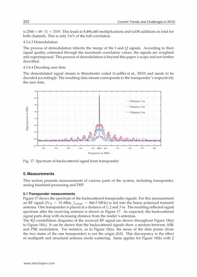
Fig. 17. Spectrum of backscattered signal from transponder
5. Measurements
This section presents measurements of various parts of the system, including transponder,analog baseband processing and DSP.
5.1 Transponder measurements
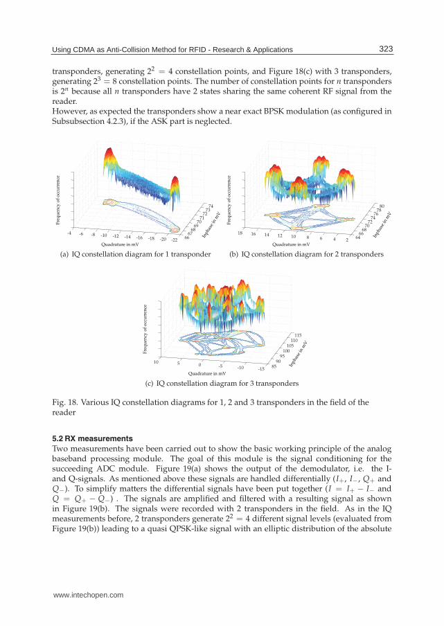
Figure 17 shows the spectrum of the backscattered transponder signals. For this measurementan RF signal (PTX = 10 dBm, fcarrier = 866.5 MHz) is fed into the linear polarized transmitantenna. One transponder is placed at a distance of 1, 2 and 3 m. The resulting reflected signalspectrum after the receiving antenna is shown in Figure 17. As expected, the backscatteredsignal parts drop with increasing distance from the reader’s antennas.The IQ constellation diagrams of the received RF signal are shown throughout Figure 18(a)to Figure 18(c). It can be shown that the backscattered signals show a mixture between ASKand PSK modulation. For instance, as in Figure 18(a), the mean of the data points (fromthe two states of the one transponder) is not the origin (0,0). This discrepancy is the effectof multipath and structural antenna mode scattering. Same applies for Figure 18(b) with 2
322 Current Trends and Challenges in RFID
www.intechopen.com
Using CDMA as Anti-Collision Method
for RFID - Research & Applications 19
transponders, generating 22 = 4 constellation points, and Figure 18(c) with 3 transponders,generating 23 = 8 constellation points. The number of constellation points for n transpondersis 2n because all n transponders have 2 states sharing the same coherent RF signal from thereader.However, as expected the transponders show a near exact BPSK modulation (as configured inSubsubsection 4.2.3), if the ASK part is neglected.
Inph
ase
inm
V
Quadrature in mV
Fre
qu
ency
of
occ
urr
ence
6667
6869
7071
7273
74
-22-20-18-16-14-12-10-8-6-4
(a) IQ constellation diagram for 1 transponder
Inph
ase
inm
V
Quadrature in mV
Fre
qu
ency
of
occ
urr
ence
6466
6870
7274
7678
80
24681012141618
(b) IQ constellation diagram for 2 transponders
Inph
ase
inm
V
Quadrature in mV
Fre
qu
ency
of
occ
urr
ence
8590
95100
105110
115
-15-10-50510
(c) IQ constellation diagram for 3 transponders
Fig. 18. Various IQ constellation diagrams for 1, 2 and 3 transponders in the field of thereader
5.2 RX measurements
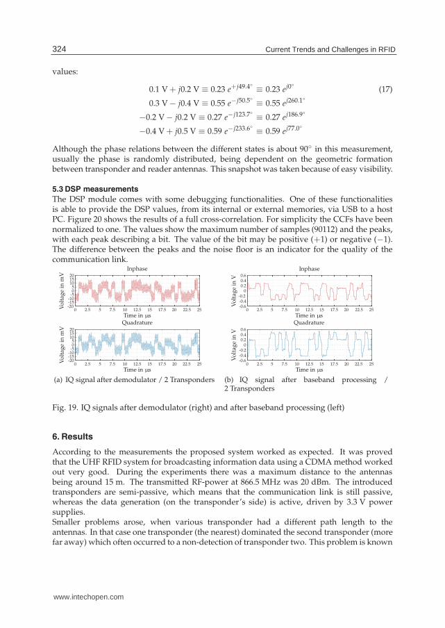
Two measurements have been carried out to show the basic working principle of the analogbaseband processing module. The goal of this module is the signal conditioning for thesucceeding ADC module. Figure 19(a) shows the output of the demodulator, i.e. the I-and Q-signals. As mentioned above these signals are handled differentially (I+, I−, Q+ andQ−). To simplify matters the differential signals have been put together (I = I+ − I− andQ = Q+ − Q−) . The signals are amplified and filtered with a resulting signal as shownin Figure 19(b). The signals were recorded with 2 transponders in the field. As in the IQmeasurements before, 2 transponders generate 22 = 4 different signal levels (evaluated fromFigure 19(b)) leading to a quasi QPSK-like signal with an elliptic distribution of the absolute
323Using CDMA as Anti-Collision Method for RFID - Research & Applications
www.intechopen.com
20 Will-be-set-by-IN-TECH
values:
0.1 V + j0.2 V ≡ 0.23 e+j49.4◦ ≡ 0.23 ej0◦ (17)
0.3 V − j0.4 V ≡ 0.55 e−j50.5◦ ≡ 0.55 ej260.1◦
−0.2 V − j0.2 V ≡ 0.27 e−j123.7◦ ≡ 0.27 ej186.9◦
−0.4 V + j0.5 V ≡ 0.59 e−j233.6◦ ≡ 0.59 ej77.0◦
Although the phase relations between the different states is about 90◦ in this measurement,usually the phase is randomly distributed, being dependent on the geometric formationbetween transponder and reader antennas. This snapshot was taken because of easy visibility.
5.3 DSP measurements
The DSP module comes with some debugging functionalities. One of these functionalitiesis able to provide the DSP values, from its internal or external memories, via USB to a hostPC. Figure 20 shows the results of a full cross-correlation. For simplicity the CCFs have beennormalized to one. The values show the maximum number of samples (90112) and the peaks,with each peak describing a bit. The value of the bit may be positive (+1) or negative (−1).The difference between the peaks and the noise floor is an indicator for the quality of thecommunication link.
Time in µs
Vo
ltag
ein
mV
Inphase
Time in µs
Vo
ltag
ein
mV
Quadrature
0 2.5 5 7.5 10 12.5 15 17.5 20 22.5 25
0 2.5 5 7.5 10 12.5 15 17.5 20 22.5 25
-20-15-10-505
101520
-20-15-10-505
101520
(a) IQ signal after demodulator / 2 Transponders
Time in µs
Vo
ltag
ein
V
Inphase
Time in µs
Vo
ltag
ein
V
Quadrature
0 2.5 5 7.5 10 12.5 15 17.5 20 22.5 25
0 2.5 5 7.5 10 12.5 15 17.5 20 22.5 25
-0.6-0.4-0.2
00.20.40.6
-0.6-0.4-0.2
00.20.40.6
(b) IQ signal after baseband processing /2 Transponders
Fig. 19. IQ signals after demodulator (right) and after baseband processing (left)
6. Results
According to the measurements the proposed system worked as expected. It was provedthat the UHF RFID system for broadcasting information data using a CDMA method workedout very good. During the experiments there was a maximum distance to the antennasbeing around 15 m. The transmitted RF-power at 866.5 MHz was 20 dBm. The introducedtransponders are semi-passive, which means that the communication link is still passive,whereas the data generation (on the transponder’s side) is active, driven by 3.3 V powersupplies.Smaller problems arose, when various transponder had a different path length to theantennas. In that case one transponder (the nearest) dominated the second transponder (morefar away) which often occurred to a non-detection of transponder two. This problem is known
324 Current Trends and Challenges in RFID
www.intechopen.com

Using CDMA as Anti-Collision Method
for RFID - Research & Applications 21
Sample index
No
rmal
ized
CC
FCCF of Q component with Code 1 (Transponder 1)
Sample index
No
rmal
ized
CC
F
CCF of I component with Code 2 (Transponder 2)
0 10000 20000 30000 40000 50000 60000 70000 80000 90000
0 10000 20000 30000 40000 50000 60000 70000 80000 90000
-1
-0.5
0
0.5
1
-1
-0.5
0
0.5
1
Fig. 20. Cross-correlation of signals with origin spreading codes - Process of despreading /2 Transponders
in CDMA systems and is referred to as near-far problem (Andrews, 2005). One possibilityto reduce the near-far effect is the usage of Huffman sequences (Liu & Guo, 2008). But thisapproach asks for more than 2 states of the load impedance of the transponder’s modulator.Nevertheless, carried out indoor experiments showed that the near-far effect of the proposedsystem is, in fact, very low.Also, theoretical work, which states an advantage (this statement is only valid for certaincases) of CDMA-based RFID systems compared to state-of-the-art RFID systems based onTDMA methods, complies with the measured results of the proposed CDMA-based UHFRFID system.
7. Conclusion
This article presented an implementation of a CDMA-based RFID system working in theUHF region. At the beginning the article gave a short introduction to anti-collision methodsused in RFID technology. Subsequently, a performance comparison was made to show theeffect of using CDMA in RFID. It could be stated, that CDMA does outperform traditionalTDMA methods, but only in particular fields of applications. The implemented RFID systemitself is build upon a Transmitting system providing a continuous electromagnetic wave. Thisemitted RF carrier is backscattered through one or more designed UHF tags. Each of thesesemi-passive operating transponders generate a unique spreading sequence. The proposedspreading sequences are Gold codes providing a good orthogonality. A simple modulatoron the transponder generates the desired backscatter signal. The Receiving system capturesthis signal by down mixing the RF signal to baseband. Further analog signal processing andsubsequent A/D conversion gives the DSP the chance to despread, demodulate and decodethe desired transponder signals.The significant advantage of such a structure compared to present systems lies in the abilityto avoid particular TDMA-based anti-collision schemes. Certainly, this will lead to less timeneeded for inventorizing RFID tags, as this can be achieved within one time slot. However, thenumber of tags to be read this way, is somewhat limited (due to the usage of CDMA), whereasTDMA methods may recognize a huge amount of transponders, indeed, at the expense of timeto identify. Finally, one can say, that the deployment of CDMA is useful in cases where thenumber of transponders has an upper limit or is fixed. For such cases the time for detection
325Using CDMA as Anti-Collision Method for RFID - Research & Applications
www.intechopen.com
22 Will-be-set-by-IN-TECH
may be minimized using appropriate spreading codes. Fields of application mainly includeclosed systems, e.g., found in industrial facilities.
8. Acknowledgment
I would like to thank Fabian Schuh, and in particular Ingo Altmann, without whom thispublication would not have been possible. His ideas, work, and research on this topic madea big contribution to this chapter. Also, I would like to thank my colleagues for their veryproductive ideas and valuable discussions.To my wife Sonja, my daughters Jenny and Jolina, and my son Tom, for having the patiencewith me, despite my long periods in the office which decrease the amount of time I can spendwith them.
9. References
Abramson, N. (1970). THE ALOHA SYSTEM: another alternative for computercommunications, Proceedings of the November 17-19, 1970, fall joint computer conference,AFIPS ’70 (Fall), ACM, New York, NY, USA, pp. 281–285.URL: http://doi.acm.org/10.1145/1478462.1478502
Aein, Joseph M. (1964). Multiple Access to a Hard-Limiting Communication-SatelliteRepeater, Space Electronics and Telemetry, IEEE Transactions on 10(4): 159–167.URL: 10.1109/TSET.1964.4337583
Analog Devices (2010a). AD9248: Dual 14-Bit, 20/40/65 MSPS, 3 V Analog-to-DigitalConverter.URL: http://www.analog.com/en/analog-to-digital-converters/ad-converters/ad9248/products/product.html
Analog Devices (2010b). ADSP-21469: High Performance Fourth Generation DSP.URL: http://www.analog.com/en/embedded-processing-dsp/sharc/adsp-21469/processors/product.html
Andrews, J. (2005). Interference cancellation for cellular systems: A contemporary overview,IEEE Wireless Communications 12(2): 19–29.
Bang, O., Kim, S. & Lee, H. (2009). Identification of RFID tags in dynamic framed slottedAloha, Advanced Communication Technology, 2009. ICACT 2009. 11th InternationalConference on, Vol. 01, pp. 354 –357.
Bertsekas, D. & Gallager, R. (1992). Data networks (2nd ed.), Prentice-Hall, Inc., Upper SaddleRiver, NJ, USA.
Choi, J. H., Lee, D. & Lee, H. (2007). Query tree-based reservation for efficient RFID taganti-collision, Communications Letters, IEEE 11(1): 85 –87.
Cui, Y. & Zhao, Y. (2009). A modified Q-parameter anti-collision scheme for RFID systems,Ultra Modern Telecommunications Workshops, 2009. ICUMT ’09. International Conferenceon, pp. 1 –4.
Dobkin, D. (2008). The RF in RFID: passive UHF RFID in practice, Newnes.EPCglobal Inc. (2008). Class 1 Generation 2 UHF Air Interface Protocol Standard "Gen 2" v.
1.2.0.Finkenzeller, K. (2003). RFID handbook, Wiley West Sussex, England.Fuschini, F., Piersanti, C., Paolazzi, F. & Falciasecca, G. (2008). On the Efficiency of Load
Modulation in RFID Systems Operating in Real Environment, Antennas and WirelessPropagation Letters, IEEE 7: 243 –246.
326 Current Trends and Challenges in RFID
www.intechopen.com

Using CDMA as Anti-Collision Method
for RFID - Research & Applications 23
Gold, R. (1967a). Optimal binary sequences for spread spectrum multiplexing (corresp.),Information Theory, IEEE Transactions on 13(4): 619 – 621.
Gold, R. (1967b). Optimal binary sequences for spread spectrum multiplexing (Corresp.),Information Theory, IEEE Transactions on 13(4): 619 – 621.
Gopalan, S., Karystinos, G. & Pados, D. (2005). Capacity, throughput, and delay ofslotted ALOHA DS-CDMA links with adaptive space-time auxiliary-vector receivers,Wireless Communications, IEEE Transactions on 4(1): 79 – 92.
Hansen, R. (1989). Relationships between antennas as scatterers and as radiators, Proceedingsof the IEEE 77(5): 659 –662.
IPICO (2009). IPICO’s IP-X RFID Air-interface Protocol.URL: http://www.ipico.com/
Karthaus, U. & Fischer, M. (2003). Fully integrated passive uhf rfid transponder ic with 16, 7μwminimum rf input power, IEEE 38(10): 1602–1608.
Kleinrock, L. & Tobagi, F. (1975). Packet Switching in Radio Channels: PartI–Carrier Sense Multiple-Access Modes and Their Throughput-Delay Characteristics,Communications, IEEE Transactions on 23(12): 1400 – 1416.
Lee, D., Bang, O., Im, S. & Lee, H. (2008). Efficient dual bias Q-Algorithm and optimumweights for EPC Class 1 Generation 2 Protocol, Wireless Conference, 2008. EW 2008.14th European, pp. 1 –5.
Linear Technology (2010a). LT5575 - 800MHz to 2.7GHz High Linearity Direct ConversionQuadrature Demodulator.URL: http://www.linear.com/pc/productDetail.jsp?navId=H0,C1,C1011,C1725,P36240
Linear Technology (2010b). LT6604-2.5 - Dual Very Low Noise, Differential Ampli?er and2.5MHz Lowpass Filter.URL: http://www.linear.com/pc/productDetail.jsp?navId=H0,C1,C1154,C1008,C1148,P85251
Linear Technology (2010c). LTC6420-20 - Dual Matched 1.8GHz Differential Amplifiers/ADCDrivers.URL: http://www.linear.com/pc/productDetail.jsp?navId=H0,C1,C1154,C1009,C1126,P80614
Linear Technology (2010d). LTC6421-20 - Dual Matched 1.3GHz Differential Amplifiers/ADCDrivers.URL: http://www.linear.com/pc/productDetail.jsp?navId=H0,C1,C1154,C1009,C1126,P80589
Linnartz, J.-P. M. & Vvedenskaya, N. D. (2009). DS-CDMA Packet Network with RandomAccess.URL: http://www.wirelesscommunication.nl/reference/chaptr06/stack/cdmastck.htm
Liu, D., Wang, Z., Tan, J., Min, H. & Wang, J. (2009). ALOHA algorithm considering theslot duration difference in RFID system, RFID, 2009 IEEE International Conference on,pp. 56 –63.
Liu, H. & Guo, X. (2008). A passive UHF RFID system with Huffman sequence spreadingbackscatter signals, Proceedings of the 1st international conference on The internet ofthings, Springer-Verlag, pp. 184–195.
Liu, Q., Yang, E.-H. & Zhang, Z. (2001). Throughput analysis of CDMA systems usingmultiuser receivers, Communications, IEEE Transactions on 49(7): 1192 –1202.
Liu, Z. & El Zarki, M. (1994). Performance analysis of DS-CDMA with slotted ALOHArandom access for packet PCNs, Personal, Indoor and Mobile Radio Communications,1994. Wireless Networks - Catching the Mobile Future., 5th IEEE International Symposiumon, Vol. 4, pp. 1034 –1039 vol.4.
327Using CDMA as Anti-Collision Method for RFID - Research & Applications
www.intechopen.com
24 Will-be-set-by-IN-TECH
Lo, F. L., Ng, T. S. & Yuk, T. (1996). Performance analysis of a fully-connected, full-duplexCDMA ALOHA network with channel sensing and collision detection, Selected Areasin Communications, IEEE Journal on 14(9): 1708 –1716.
Loeffler, A., Schuh, F. & Gerhaeuser, H. (2010). Realization of a CDMA-based RFID SystemUsing a Semi-active UHF Transponder, Wireless and Mobile Communications (ICWMC),2010 6th International Conference on, pp. 5 –10.
Maguire, Y. & Pappu, R. (2009). An Optimal Q-Algorithm for the ISO 18000-6C RFID Protocol,Automation Science and Engineering, IEEE Transactions on 6(1): 16 –24.
Makwimanloy, S., Kovintavewat, P., Ketprom, U. & Tantibundhit, C. (2009). A novelanti-collision algorithm for high-density RFID tags, Electrical Engineering/Electronics,Computer, Telecommunications and Information Technology, 2009. ECTI-CON 2009. 6thInternational Conference on, Vol. 02, pp. 848 –851.
Mutti, C. & Floerkemeier, C. (2008). CDMA-based RFID Systems in Dense Scenarios: Conceptsand Challenges, RFID, 2008 IEEE International Conference on, pp. 215–222.
Nikitin, P. & Rao, K. (2008). Antennas and propagation in uhf rfid systems, RFID, 2008 IEEEInternational Conference on, pp. 277 –288.
Pardo, D., Vaz, A., Gil, S., Gomez, J., Ubarretxena, A., Puente, D., Morales-Ramos, R.,Garcia-Alonso, A. & Berenguer, R. (2007). Design criteria for full passive longrange uhf rfid sensor for human body temperature monitoring, RFID, 2007. IEEEInternational Conference on, pp. 141–148.
Penttila, K., Keskilammi, M., Sydanheimo, L. & Kivikoski, M. (2006). Radar cross-sectionanalysis for passive RFID systems, Microwaves, Antennas and Propagation, IEEProceedings - 153(1): 103 – 109.
Pupunwiwat, P. & Stantic, B. (2010). A RFID Explicit Tag Estimation Scheme for DynamicFramed-Slot ALOHA Anti-Collision, Wireless Communications Networking and MobileComputing (WiCOM), 2010 6th International Conference on, pp. 1 –4.
Rembold, B. (2009). Optimum modulation efficiency and sideband backscatter powerresponse of RFID-tags, Frequenz - Journal of RF-Engineering and Telecommunications63(1 -2): 9 –13.
Roberts, L. G. (1975). ALOHA packet system with and without slots and capture, SIGCOMMComput. Commun. Rev. 5: 28–42.URL: http://doi.acm.org/10.1145/1024916.1024920
Sakata, A., Yamazato, T., Okada, H. & KATAYAMAt, M. (2007). ThroughputComparison of CSMA and CDMA slotted ALOHA in Inter-Vehicle Communication,Telecommunications, 2007. ITST ’07. 7th International Conference on ITS, pp. 1 –6.
Sastry, A. (1984). Effect of Acknowledgment Traffic on the Performance of SlottedALOHA-Code Division Multiple Access Systems, Communications, IEEE Transactionson 32(11): 1219 – 1222.
van Nee, R., van Wolfswinkel, R. & Prasad, R. (1995). Slotted ALOHA and code divisionmultiple access techniques for land-mobile satellite personal communications,Selected Areas in Communications, IEEE Journal on 13(2): 382 –388.
Wang, L.-C. & Liu, H.-C. (2006). A Novel Anti-Collision Algorithm for EPC Gen2RFID Systems, Wireless Communication Systems, 2006. ISWCS ’06. 3rd InternationalSymposium on, pp. 761 –765.
Zhang, Z., Lu, Z., Pang, Z., Yan, X., Chen, Q. & Zheng, L.-R. (2010). A LowDelay Multiple Reader Passive RFID System Using Orthogonal TH-PPM IR-UWB,Computer Communications and Networks (ICCCN), 2010 Proceedings of 19th InternationalConference on, pp. 1 –6.
328 Current Trends and Challenges in RFID
www.intechopen.com

Current Trends and Challenges in RFIDEdited by Prof. Cornel Turcu
ISBN 978-953-307-356-9Hard cover, 502 pagesPublisher InTechPublished online 20, July, 2011Published in print edition July, 2011
InTech EuropeUniversity Campus STeP Ri Slavka Krautzeka 83/A 51000 Rijeka, Croatia Phone: +385 (51) 770 447 Fax: +385 (51) 686 166www.intechopen.com
InTech ChinaUnit 405, Office Block, Hotel Equatorial Shanghai No.65, Yan An Road (West), Shanghai, 200040, China
Phone: +86-21-62489820 Fax: +86-21-62489821
With the increased adoption of RFID (Radio Frequency Identification) across multiple industries, new researchopportunities have arisen among many academic and engineering communities who are currently interested inmaximizing the practice potential of this technology and in minimizing all its potential risks. Aiming at providingan outstanding survey of recent advances in RFID technology, this book brings together interesting researchresults and innovative ideas from scholars and researchers worldwide. Current Trends and Challenges inRFID offers important insights into: RF/RFID Background, RFID Tag/Antennas, RFID Readers, RFID Protocolsand Algorithms, RFID Applications and Solutions. Comprehensive enough, the present book is invaluable toengineers, scholars, graduate students, industrial and technology insiders, as well as engineering andtechnology aficionados.
How to referenceIn order to correctly reference this scholarly work, feel free to copy and paste the following:
Andreas Loeffler (2011). Using CDMA as Anti-Collision Method for RFID - Research & Applications, CurrentTrends and Challenges in RFID, Prof. Cornel Turcu (Ed.), ISBN: 978-953-307-356-9, InTech, Available from:http://www.intechopen.com/books/current-trends-and-challenges-in-rfid/using-cdma-as-anti-collision-method-for-rfid-research-applications