Embed Size (px)
Citation preview

THE OXIDATION OF CARBON MONOXIDE
USING A T I N OXIDE CATALYST
Chris topher F. Sampson and Nicholas J . Gudde United Kingdom Atomic Energy Author i ty
A.E.R.E. H a r w e l l , Didcot, Oxon. United Kingdom
SUMMARY
This paper o u t l i n e s some of the s t e p s involved i n t h e development by t h e United Kingdom Atomic Energy Author i ty (UKAEA) of a c a t a l y t i c device f o r t h e recombination of carbon monoxide and oxygen i n a C02 laser sys t em.
It c o n t r a s t s t h e d i f f e r e n c e s between CO o x i d a t i o n f o r a i r p u r i f i c a t i o n and f o r l a s e r environmental c o n t r o l , but i n d i c a t e s t h a t t h e r e a r e similarities between t h e phys ica l s p e c i f i c a t i o n s . The p r i n c i p a l f e a t u r e s of c a t a l y t i c devices are o u t l i n e d and some experimental work descr ibed . This inc ludes measurements concerning t h e s t r u c t u r e and mechanical p r o p e r t i e s of t h e a r t i f a c t , t h e p repa ra t ion of t h e c a t a l y s t coa t ing and i t s i n t e r a c t i o n with t h e gaseous environment. The paper concludes with some s p e c u l a t i o n about t h e method by which t h e r eac t ion a c t u a l l y occurs .
INTRODUCTION
During t h e l a t e 1970's, t h e United Kingdom Atomic Energy Authori ty a t Harwell became involved i n sol-gel technology as a r e s u l t of oxide f u e l development. The so l -ge l method was found t o be s u i t a b l e f o r t h e p repa ra t ion of c a t a l y t i c m a t e r i a l s which even tua l ly l e d t o t h e i r use i n car exhaust c a t a l y t i c conve r t e r s and f o r a i r p u r i f i c a t i o n c a t a l y s t s . Such c a t a l y s t s were u s u a l l y i n t h e form of coa t ings appl ied t o suppor t ing a r t i f a c t s such a s monol i ths , formed from e i t h e r c o r d i e r i t e o r from a co r ros ion r e s i s t a n t metal such a s Fec ra l loy s tee l (R). The UKAEA has experience i n t h e u s e of sol-gel c a t a l y s t s f o r CO removal from a i r and so has a t echno log ica l l i n k t o a system in tended t o recombine O2 and CO formed i n sea led C 0 2 l a s e r s .
Table 1 g i v e s t y p i c a l s p e c i f i c a t i o n s for CO o x i d a t i o n i n b rea th ing g e a r and i n a laser recombination system. The main d i f f e rence l i e s i n t h e gas composition; t h e a i r p u r i f i e r w i l l be exposed t o CO and O2 concent ra t ions cons iderably h igher than those seen by t h e recombination c a t a l y s t , but w i l l on ly encounter a f r a c t i o n of t h e C02. whereas t h e C 0 2 conten t of a i r i s < 1%. however. Carbon monoxide o x i d a t i o n i s an exothermic process , bu t both c a t a l y t i c systems must have a low exhaust temperature. The product ion of ho t a i r by a b rea th ing app l i ance can cause r e s p i r a t o r y d i f f i c u l t i e s ( c a t a l y s t s sometimes have very human f a i l i n g s ) , whereas heated gases within t h e l a s e r could r e s u l t i n o p t i c a l d i s t o r t i o n . S i m i l a r l y , mechanical i n t e g r i t y i s important t o prevent dus t and d e b r i s from Che c a t a l y s t becoming inha led o r obscuring t h e o p t i c a l system.
I n a laser environment, t h e C02 concent ra t ion might be as much as 40% by volume, The ope ra t ing requirements a r e very s i m i l a r ,
(R) Fec ra l loy s teel i s a r e g i s t e r e d trademark of t h e UKAEA.
65
https://ntrs.nasa.gov/search.jsp?R=19870011095 2018-07-11T07:57:33+00:00Z
CATALYST TEST R I G
The c a t a l y s t d e v i c e had t o b e des igned t o f i t w i t h i n t h e case of a r e c y c l e laser system w i t h o u t impeding t h e c i r c u l a t i o n o f t h e laser g a s , y e t p r o v i d i n g s u f f i c i e n t c a t a l y t i c a c t i v i t y t o e f f e c t t h e r ecombina t ion . To a c h i e v e t h e s e g o a l s , s e v e r a l t y p e s of c a t a l y s t a r t i f a c t s were c o n s i d e r e d , t h e f i n a l c h o i c e b e i n g a ceramic m o n o l i t h c o a t e d w i t h a s t r o n g l y a d h e r e n t c a t a l y s t . An example i s shown i n f i g u r e 1.
The laser tes t r i g i s shown i n f i g u r e 2 . The laser c a v i t y , which normally c o n t a i n s t h e e l e c t r o d e assembly, i s a t t h e t o p , and g a s c i r c u l a t i o n i s provided by a t a n g e n t i a l f a n s i t u a t e d a t t h e l e f t hand s i d e . The g a s m i x t u r e f lows c lockwise through t h e e l e c t r o d e assembly, t h rough t h e c a t a l y s t a r t i f a c t and may b e c o o l e d , i f n e c e s s a r y , b e f o r e r e t u r n i n g t o t h e f a n . A t y p i c a l g a s v e l o c i t y th rough t h e laser c a v i t y i s 7 m / s , which i s s u f f i c i e n t t o pas s t h r e e laser volumes pe r laser p u l s e . The mono l i th t y p i c a l l y had dimensions of 10 c m long by 5 c m wide by 2 c m deep.
CATALYST PREPARATION AND PERFORMANCE
The i n i t i a l s t a g e s of c a t a l y s t development concerned t h e p r o d u c t i o n of a t i n s o l . Of t h e c a t a l y s t f o r m u l a t i o n s t r i e d , t i n o x i d e w i t h two p r e c i o u s metal c o a t i n g s w a s found t o be t h e b e s t . S e v e r a l f a c t o r s had t o b e c o n s i d e r e d :
1. The v i s c o s i t y of t h e s o l must be low enough t h a t t h e r e i s adequa te p e n e t r a t i o n o f t h e material i n t o t h e p o r e s o f t h e s u b s t r a t e .
2 . The c o n c e n t r a t i o n of t h e s o l must be h i g h s o t h a t enough c a t a l y s t i s d e p o s i t e d i n a p r a c t i c a l number of c o a t i n g s t e p s .
3 . The s o l must form a c a t a l y s t w i t h a h i g h s u r f a c e area.
4 . The f i n a l c a t a l y s t c o a t i n g must a d h e r e t o t h e ceramic s u b s t r a t e .
5 . The p rec ious metal shou ld b e u n i f o r m l y d i s t r i b u t e d o v e r t h e s u r f a c e o f t h e c a t a l y s t .
Some o f t h e s e r equ i r emen t s a re i n c o m p a t i b l e , and so a compromise must be s o u g h t , f o r example between c o n c e n t r a t i o n and v i s c o s i t y . It i s no t j u s t t h e p h y s i c a l p r o p e r t i e s which may be a l t e r e d , one may i n f l u e n c e t h e p r o p e r t i e s of t h e c a t a l y s t by chemical means. V i s c o s i t y , f o r i n s t a n c e , depends on t h e c o n c e n t r a t i o n of t h e s o l bu t may b e i n f l u e n c e d by a d j u s t i n g t h e pH of t h e m i x t u r e .
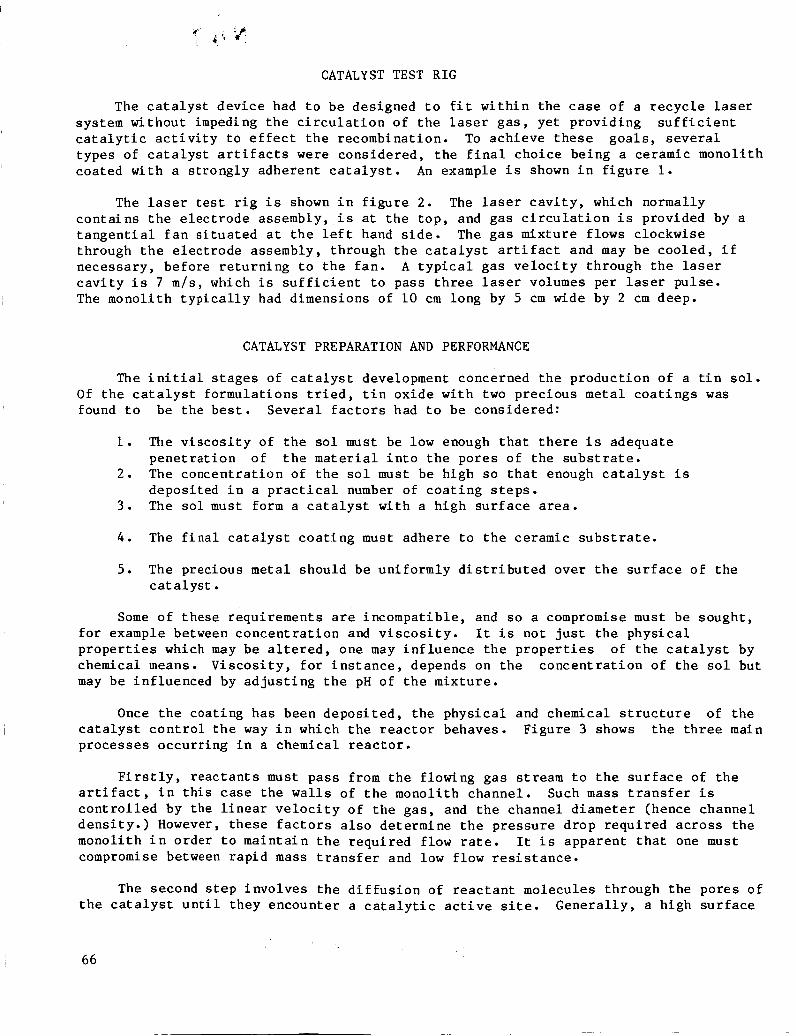
Once t h e c o a t i n g h a s been d e p o s i t e d , t h e p h y s i c a l and chemical s t r u c t u r e of t h e c a t a l y s t c o n t r o l the way i n which t h e r e a c t o r behaves. F i g u r e 3 shows t h e t h r e e main p r o c e s s e s o c c u r r i n g i n a chemical r e a c t o r .
F i r s t l y , r e a c t a n t s must p a s s from t h e f lowing g a s stream t o t h e s u r f a c e of t h e a r t i f a c t , i n t h i s case t h e wa l l s of t h e mono l i th channe l . Such mass t r a n s f e r i s c o n t r o l l e d by t h e l i n e a r v e l o c i t y o f t h e g a s , and t h e channe l d i a m e t e r (hence c h a n n e l d e n s i t y . ) However, t h e s e f a c t o r s a l s o de t e rmine t h e p r e s s u r e d r o p r e q u i r e d a c r o s s t h e mono l i th i n o r d e r t o m a i n t a i n t h e r e q u i r e d f low ra te . It i s a p p a r e n t t h a t one must compromise between r a p i d mass t r a n s f e r and low f low r e s i s t a n c e .
The second s t e p i n v o l v e s t h e d i f f u s i o n of r e a c t a n t mo lecu le s th rough t h e p o r e s o f t h e c a t a l y s t u n t i l t h e y e n c o u n t e r a c a t a l y t i c a c t i v e s i te . G e n e r a l l y , a h i g h s u r f a c e
66

area support w i l l g ive more a c t i v e si tes per u n i t volume of c a t a l y s t . high su r face areas are normally assoc ia ted with pores of small diameter which restrict d i f f u s i o n more than would l a r g e pores. Again, a balance must be a t t a i n e d . The s t r u c t u r a l s t a b i l i t y of t h e coa t ing may a l s o be e f f e c t e d by t h e pore s t r u c t u r e .
Unfortunately,
F i n a l l y , t h e recombination r e a c t i o n occurs a t t he a c t i v e s i t e . Chemical f a c t o r s are ve ry important ; impur i t i e s may poison the r e a c t i o n , t h e form of t h e prec ious metal may be inf luenced by t h e precious metal salt used f o r depos i t i on , t h e p u r i t y and s t r u c t u r e of t h e t i n oxide may e f f e c t both the d i spe r s ion of t h e precious metal and t h e r e a c t i o n i t s e l f .
The removal of products may a l s o play a p a r t , e s p e c i a l l y i f t he products can react with t h e c a t a l y s t . I f product molecules remain a t tached t o t h e c a t a l y s t su r f ace , they may impede the r e a c t i o n by blocking the d i f f u s i o n of reagents o r by changing the chemical p r o p e r t i e s of the c a t a l y s t .
EXAMPLES OF CATALYST OPTIMIZATION AND TESTING
Surface Area
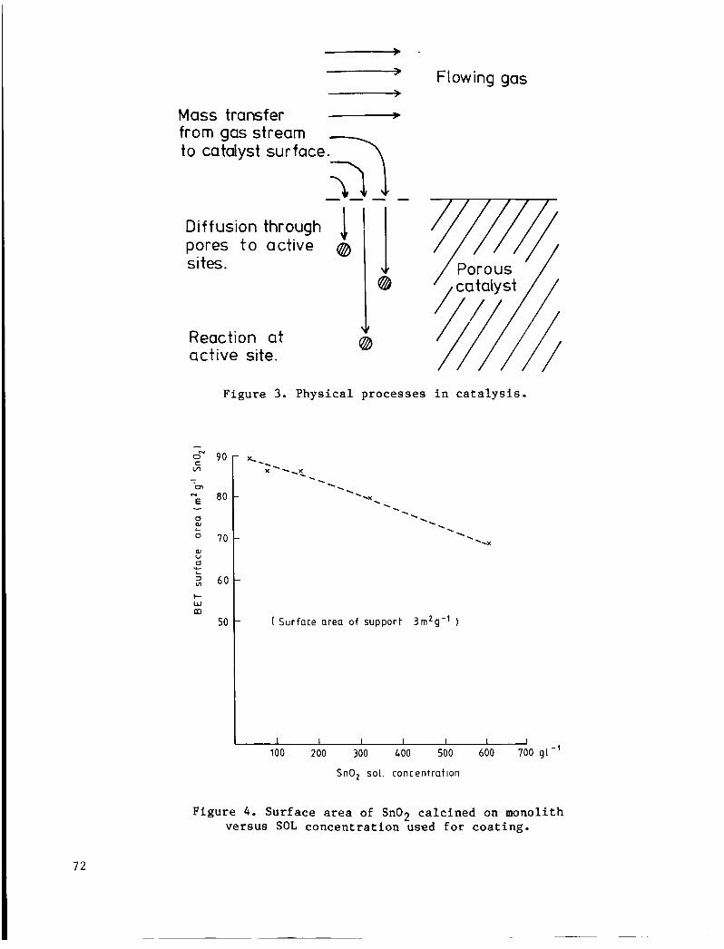
Figure 4 shows the r e s u l t s of an experiment which measured t h e e f f e c t of s o l concen t r a t ion on the BET su r face area of the c a t a l y s t coa t ing . These r e s u l t s have been co r rec t ed f o r t h e s u r f a c e area of t h e c o r d i e r i t e support (ca. 3m2/g). shows t h a t t h e h ighes t su r f ace areas were obtained from t h e lowest concen t r a t ion s o l s . Af te r op t imiza t ion , an improved s o l w a s prepared. This had a concent ra t ion of 200 g / 1 and gave a coa t ing with a su r face area between 150 and 200 m2/g.
The graph
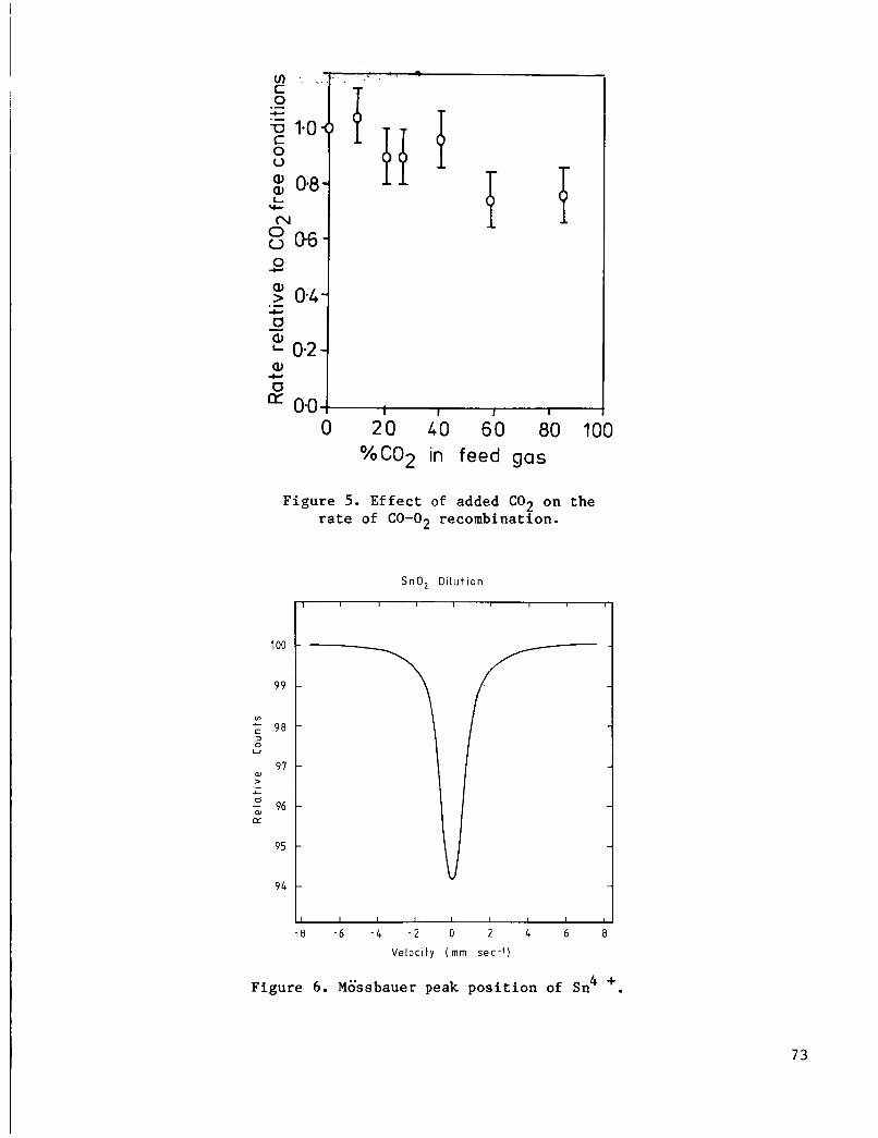
Ef fec t Of High Concentrat ions Of C 0 2
It was not known whether t h e l a r g e p a r t i a l p ressure of C 0 2 would have any e f f e c t on t h e a c t i v i t y of t h e c a t a l y s t . The rate of recombination w a s measured f o r a s t o i c h i o m e t r i c mixture of 1% CO, 0.5% O2 i n var ious He/CO
recombination i n a C02-free atmosphere. a t concen t r a t ions below 50 ~ 0 1 % . 70% of t h e C02-free value.
mixtures .
Carbon d ioxide has l i t t l e i n h i b i t i n g e f f e c t
The r e s u l t s i n f i g u r e 5 show t h e rate at a given C 0 2 concent ra t ion re la t 1 ve t o the ra te of
Even above 90 vol% C 0 2 , t he ra te was only reduced t o
Reduction Of The Support By CO
The presence of CO i n t h e gas mixture could have modified the su r face of t h e t i n oxide . Mossbauer spectroscopy can d i s t i n g u i s h between Sn(1V) and Sn( 11) , so an experiment w a s undertaken t o observe t h e e f f e c t of CO on a c a t a l y s t a t room temperature . S i g n i f i c a n t reduct ion of t h e c a t a l y s t would have introduced a Sn(I1) peak i n a d d i t i o n t o t h e Sn(1V). The spec t r a i n f i g u r e 6 show t h a t no Sn(I1) could be observed. This sugges ts t h a t e i t h e r CO did not reduce the c a t a l y s t , o r t h a t t h e c a t a l y s t had r eve r t ed t o i t s o r i g i n a l form because of oxygen i n t h e environment.
Ca ta lys t D i s t r i b u t i o n
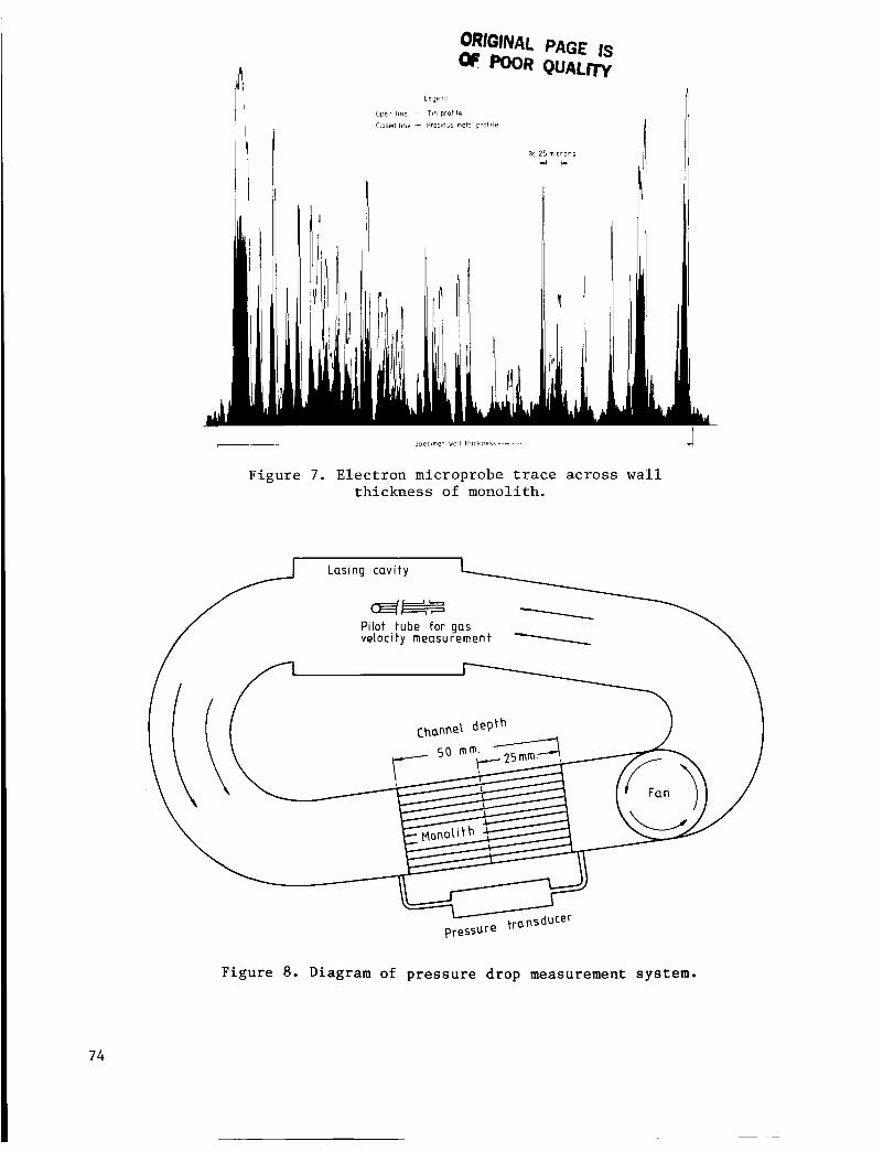
The c a t a l y t i c a l l y a c t i v e material (prec ious metal on t i n oxide) was coated on a porous c o r d i e r i t e monolith. For maximum a c t i v i t y , one must ensure t h a t t h e device suppor ts t h e maximum amount of c a t a l y s t , i e . ensure t h a t a l l the pores
67

of t h e c o r d i e r i t e have been coated wi th c a t a l y s t . I f t h i s cond i t ion has been f u l f i l l e d , then t h e prec ious meta ls w i l l be uniformly d i s t r i b u t e d throughout t h e wa l l of t h e monolith. F igure 7 shows an e l e c t r o n microprobe t r a c e a c r o s s t h e th i ckness of a f i n i s h e d monolith wa l l . The t i n s i g n a l shows t h a t t h e t i n oxide p r o f i l e i s matched c l o s e l y by t h e precious metal, and dec reases s l i g h t l y towards t h e c e n t e r of t h e wa l l . Although t h e p r o f i l e s a r e not uniform, they do show t h a t t h e s u b s t r a t e i s porous and t h a t t h e c a t a l y t i c m a t e r i a l s have penet ra ted w e l l w i th in t h e s u b s t r a t e .
Mechanical P r o p e r t i e s
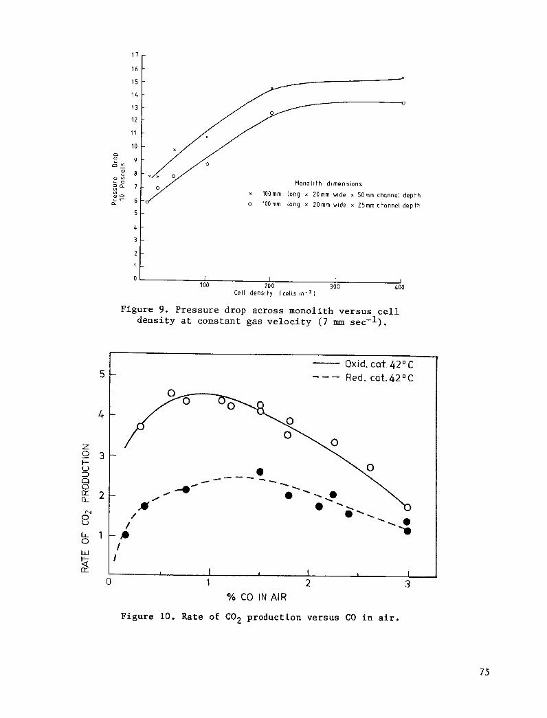
The i n c l u s i o n of a c a t a l y s t i n t h e l a s e r dev ice may e f f e c t t h e s t a b i l i t y of t h e ins t rument by c r e a t i n g dus t o r o b s t r u c t i n g t h e flow of gas . p re s su re drop measurements were made by measuring t h e d i f f e r e n t i a l t h e c a t a l y s t a r t i f a c t a s shown i n f i g u r e 8. a f t e r t h e monolith holder i n t h e l a s e r c a s e , and t h e gas v e l o c i t y measured us ing a p i t o t tube f i t t e d i n t o t h e laser cav i ty . versus c e l l dens i ty f o r monoliths of d i f f e r e n t depth. The gas l i n e a r v e l o c i t y was kep t cons tan t throughout. c e l l d e n s i t i e s was approximately twice t h a t of t h e lower d e n s i t i e s .
To s tudy t h e l a t t e r , p re s su re a c r o s s
Measuring p o r t s were l o c a t e d before and
Figure 9 shows two curves of p re s su re drop
For both monolith depths , t h e p re s su re drop f o r t h e h igher
Mechanical s t r eng th and r e s i s t a n c e t o dus t ing of t h e appl ied coa t ing a r e very important because of p o t e n t i a l damage t o t h e o p t i c a l system. Shock and v i b r a t i o n tests were c a r r i e d out by weighing t h e c a t a l y s t a r t i f a c t s before and a f t e r va r ious
2 t r ea tmen t s . The shock t e s t used a 981 m / s ha l f - s ine 6 m s pu lse app l i ed t h r e e times a l o g t h r e e mutually perpendicular planes. The v i b r a t i o n test used a 20-500 Hz, 19.8 m/s ' a c c e l e r a t i o n f o r two hours , aga in along t h r e e mutual ly perpendicular p lanes . No loss of weight was de t ec t ed i n e i t h e r tes t .
MECHANISTIC STUDIES
The mechanism of a c a t a l y t i c r e a c t i o n can o f t e n i n d i c a t e how t h e c a t a l y s t works, and so i n d i c a t e which aspects i f i t s formulat ion w i l l most b e n e f i t i t s performance. F igure 10 shows the r a t e of formation of C 0 2 f o r d i f f e r e n t concen t r a t ions of CO i n a i r . The s o l i d curve i s from a c a t a l y s t reduced i n hydrogen before use ; t h e dashed curve i s from an unreduced c a t a l y s t . Both curves show t h a t t h e r e i s a maximum rate of r e a c t i o n which occurs between 1.0 and 1.5 vol% of CO, and t h a t h igher concen t r a t ions of CO do not cause a n i n c r e a s e in t h e r a t e as would be expected from a s imple (pseudo) f i r s t - o r d e r process ( i . e . , i n a i r , t h e oxygen i s always i n s t o i c h i o m e t r i c excess . This i s simply explained i n terms of s t rong adso rp t ion of CO. t h e r a t e of ox ida t ion of CO i s high enough t o keep t h e s u r f a c e of t h e c a t a l y s t f a i r l y f r e e of adsorbed CO. A t h igh p res su res , t h e s u r f a c e becomes covered wi th unreac ted C O which b locks the supply of oxygen and so causes a r educ t ion i n t h e o v e r a l l r a t e even though the re i s p len ty of CO a v a i l a b l e .
A t low CO p r e s s u r e s ,
To observe the e f f e c t of CO and O2 p a r t i a l p re s su res , two experiments were conducted us ing powdered samples of c a t a l y s t he ld a t 3 0 ° C i n a d i f f e r e n t i a l r e a c t o r . The test gas contained CO and O2 i n a helium car r ie r . F igures l l a and l l b show t h e rates of C 0 2 production a s func t ions of CO and O2 p a r t i a l p r e s s u r e s , r e s p e c t i v e l y . e i t h e r c a s e , t h e o the r reagent concen t r a t ion was he ld cons t an t . t o be zero o rde r with r e spec t t o CO, but f i r s t o rde r wi th r e spec t t o 02. i n d i c a t e s t h a t under l a s e r recombination cond i t ions , t h e s u r f a c e always holds i t s maximum amount of CO and t h e ra te l i m i t i n g s t e p i s t h e supply of oxygen ( e i t h e r atoms o r molecules) t o combine wi th t h e CO.
I n The r e a c t i o n appears
This
68

Prof . Bond ( r e f . 1) has s tud ied t h e r eac t ion of CO i n a i r on a Pd/alumina c a t a l y s t a t 15OoC., and has proposed a "spi l l -over" mechanism t o exp la in t h e r e s u l t s . Our resu l t s are c o n s i s t e n t with our technica l c a t a l y s t ope ra t ing by t h i s type of mechanism a t room temperature . A poss ib l e sp i l l -ove r mechanism i s shown i n f i g u r e 12. I n t h e f i r s t s t e p , a CO molecule from t h e gas phase a r r i v e s a t a prec ious metal s i t e , becomes a c t i v a t e d (eg. v i b r a t i o n a l l y ) then s p i l l s over on to the t i n oxide su r face . The CO molecule a b s t r a c t s an oxygen atom and forms a C02 molecule which desorbs back i n t o t h e gas phase. An oxygen vacancy i s l e f t i n t h e su r face . Reoxidation of t h e s u r f a c e occurs by a s i m i l a r process i n s t e p 2. Oxygen may s p i l l over e i t h e r a s atoms o r molecules (eg. d i s s o c i a t i v e redox o r Mars-van Krevelen models); t h e important s t e p i s t h e r e f i l l i n g of t h e vacancy. I n h i b i t i o n occurs when adsorbed CO blocks t h e resupply of t h e oxygen. Th i s would i n d i c a t e t h a t t h e c a t a l y s t can be improved i f t h e CO bond t o t h e s u r f a c e could be weakened (choice of prec ious meta l , a d d i t i v e s , and p re t r ea tmen t ) .
CONCLUSIONS
This p a p e r i n d i c a t e s how a c a t a l y t i c device i s developed. There are cons ide ra t ions t o be made regard ing t h e means of support ing t h e c a t a l y s t , t h e method of p repa ra t ion , both chemical and phys ica l , and an understanding of t he way i n which t h e f i n a l device w i l l work. None of t h e s e can be t r e a t e d t r u l y i n i s o l a t i o n as t h e i r i n t e r a c t i o n i s s u r p r i s i n g l y complex.
Reference
1 Bond G.C., F u l l e r M . J . , Molloy L.R., Proc. 6 t h I n t . Congr. Cat. 1, 356 (1977).
Ac know1 edgme n t
The United Kingdom Atomic Energy Authori ty would l i k e t o thank t h e D.C.V.D. Minis t ry of Defense f o r t h e i r coopera t ion throughout t h i s per iod of development.
69

TABLE 1
SPECIFICATION
PURIFICATION
Gas composition: CO - few %
- 20% O2
- few % c02
Temperature :
Other requirements:
ambient
low Ap
low dust
Reactor configuration: single pass
LASER --
4 1%
< 1% 20-40%
ambient
low Ap
low dust
recycle

F i g u r e 1. Ceramic monoli th coa ted c a t a l y s t .
F i g u r e 2. Laser tes t a p p a r a t u s .
7 1
Flowing gas ______3
pores t o active a sites.
~ c
Mass transfer _____)
@
to catalyst surface. 7 from gas stream
Reaction at active site.
- 0" 90 c wl - 0- l
NE 80 - CY W L
CY 70 W U
CY u- L
60 + W m
50
Figure 3. Physical processes in catalysis.
( Sur face a rea o f suppor t 3 1 ~ 1 ~ 9 - 1 I
I 1 I 1 I 1 I
100 200 300 400 500 600 700 91- '
SnO, so l . concent ra t ion
Figure 4. Surface area of Sn02 calcined on monolith versus SOL concentration used for coating.
72
Q,
cl -I 0.0 0 20 40 60 80 100
%C02 in feed gas
Figure 5. Effect of added C02 on the rate of CO-02 recombination.
SnO, D i l u t i o n
I
I I I I I I 1
-8 -6 - 4 - 2 0 2 4 6 8
Velocity ( m m sec - ' )
Figure 6. MGssbauer peak position of Sn4 +.
73
ORIGINAL PAGE IS K ) O R QUALnV
Legend
Open 11ne - TIC profi le
closed hne - Prer8ous meto! p r o f i ' e
Figure 7. E lec t ron microprobe trace across w a l l th ickness of monolith.
F i g u r e 8 . Diagram of p r e s s u r e d rop measurement system.
7 4
3
1
0 I I I I 100 200 300 400
Cell density (ce l ls in- * 1
Figure 9. Pressure drop across monolith ve r sus ce l l d e n s i t y a t cons tan t gas v e l o c i t y ( 7 mm sec- l ) .
Yo CO IN AIR
Figure 10. Rate of C02 production versus CO i n a i r .
75

- 00- 0.0 0 4 0.8 1.2
(30 'c , 0.5% 02 )
0 C
u 3 U 0
.- 0 %CO in feed gas c
YO 02 in feed gas
( 30'C, 0.6% C O )
Figure 11. Effect of CO and 02 partial pressure on the rate of recombination.
co
a 0 c o * l /,//////////
* 02
Figure 12. Spillover model (Bond et ale)=