Embed Size (px)
Citation preview
Analysis of Borehole-Radar Reflection Data from Machiasport Maine December 2003
Scientific Investigations Report 2005-5087
In cooperation with the United States Army Corps of Engineers New England District
US Department of the Interior US Geological Survey
Analysis of Borehole-Radar Reflection Data from Machiasport Maine December 2003
By Carole D Johnson and Peter K Joesten
US Department of the Interior US Geological Survey
Prepared in cooperation with the United States Army Corps of Engineers New England District
Scientific Investigations Report 2005-5087
US Department of the InteriorGale A Norton Secretary
US Geological SurveyCharles G Groat Director
US Geological Survey Reston Virginia 2005For sale by US Geological Survey Information Services Box 25286 Denver Federal Center Denver CO 80225
For more information about the USGS and its products Telephone 1-888-ASK-USGS World Wide Web httpwwwusgsgov
Any use of trade product or firm names in this publication is for descriptive purposes only and does not imply endorsement by the US Government
Although this report is in the public domain permission must be secured from the individual copyright owners to repro-duce any copyrighted materials contained within this report
iii
Contents
Abstract 1Introduction 1
Purpose and Scope 3Description of the Study Area 4
Borehole-Radar Reflection Method 5Principles of Borehole-Radar Reflection Logging 5Equipment and Field Methods 7Data Processing Interpretation and Visualization of Results 7
Processing and Filtering of Radar Data 7Velocity and Radial Depth of Penetration 8Interpretation of Planar Reflectors 8Visualization of Radar Interpretations 8
Data from Boreholes at the Bucks Harbor Site 13Conventional Borehole-Geophysical Logs 13Integrated Analysis of Borehole-Radar Reflection Logs Geophysical Logs and Hydraulic Data 13
Borehole MW09 14Borehole MW10 23
Results of Borehole Radar Surveys at the Bucks Harbor Site 32Borehole Spacing for Tomography Surveys and Remediation 36Summary 36Acknowledgments 37References Cited 37
Figures
1 Map showing location of the boreholes at the former Air Force Radar Tracking Station in Machiasport Maine 2
2 Schematic diagram showing methods of borehole-radar data collection 4 3 Schematic diagram showing (A) transmitter and receiving antenna arrangement for single-hole
radar-reflection logging and (B) typical reflection patterns from the direct arrival and planar and point reflectors 5
4 Schematic diagram of the borehole a planar reflector and the resulting radargram 6 5 Schematic diagram of stereographic projections 9 6 Plots showing graphic representation of interpretation of single-hole radar reflectors 107 Three-dimensional box plot showing all reflectors identified in single-hole reflection logging in
MW10 from Machiasport Maine 11 8 Schematic diagram showing radar reflectors projected (A) to the land surface in a block diagram
and (B) in map view 12 9 Borehole deviation logs for borehole MW09 in Machiasport Maine 15
10 Plots showing projection tadpole and stereoplot of features interpreted in the acoustic televiewer log for borehole MW09 in Machiasport Maine 16
11 Plot showing processed 60-megahertz borehole-radar log from borehole MW09 in Machiasport Maine 20
iv
12 Plots showing projection modified tadpole and stereoplot for radar reflections identified in borehole MW09 in Machiasport Maine 21
13 Borehole deviation logs for borehole MW10 in Machiasport Maine 24 14 Plots showing projection tadpole and stereoplot for optical televiewer (OTV) and acoustic televiewer
(ATV) data collected in borehole MW10 in Machiasport Maine 25 15 Plot showing processed 60-megahertz borehole-radar log from borehole MW10 in Machiasport
Maine 29 16 Plots showing projection modified tadpole and stereoplot for radar reflections identified in borehole
MW10 in Machiasport Maine 30 17 Three-dimensional box plot showing directional single-hole borehole-radar reflectors with a
continuity factor of 1 2 3 or 4 identified from borehole MW09 in Machiasport Maine 33 18 Three-dimensional box plot showing directional single-hole borehole-radar reflectors with a
continuity factor of 1 2 or 3 identified from borehole MW10 in Machiasport Maine 33 19 Map showing strike of projected reflectors in borehole-radar logs from borehole MW09 in
Machiasport Maine 34 20 Map showing strike of projected reflectors in borehole-radar logs from borehole MW10 in
Machiasport Maine 35
Tables
1 Construction of boreholes at the former Air Force Tracking Station area at the Bucks Harbor site Machiasport Maine 13
2 Summary of acoustic televiewer data from borehole MW09 in Machiasport Maine 173 Summary of borehole-radar reflector data from borehole MW09 in Machiasport Maine 224 Summary of optical and acoustic televiewer data from borehole MW10 in Machiasport
Maine 265 Summary of borehole-radar reflector data from borehole MW10 in Machiasport Maine 31
v
Conversion Factors and Datum
Temperature in degrees Celsius (degC) may be converted to degrees Fahrenheit (degF) as follows degF = (18 x degC) + 32
Vertical coordinate information is referenced to the North American Vertical Datum of 1988 (NAVD 88) horizontal coordinate information is referenced to the North American Datum of 1983 (NAD 83) unless otherwise noted
All bearings are recorded in azimuthal (0-360) degrees east of magnetic north By convention the strikes of planar features are reported azimuthally relative to magnetic north using right-hand rule which specifies that the dip is always in a direction 90deg to the right of the strike The direction in which the reflector dips is included for clarity Hence a planar feature that strikes south and dips 40deg to the west would be denoted as N180degE 40degW
Other abbreviations used in this report
Lmin liter per minute MHz megahertz mμs meter per microsecond μs microsecond
Multiply By To obtain
centimeter (cm) 03937 inch (in)meter (m) 3281 foot (ft)meter (m) 1094 yard (yd) kilometer (km) 06214 mile (mi)
Analysis of Borehole-Radar Reflection Data from Machiasport Maine December 2003
By Carole D Johnson and Peter K Joesten
Abstract
In December 2003 the US Geological Survey in cooper-ation with the US Army Corps of Engineers collected bore-hole-radar reflection logs in two boreholes in Machiasport Maine These bedrock boreholes were drilled as part of a hydro-geologic investigation of the area surrounding the former Air Force Radar Tracking Station site on Howard Mountain near Bucks Harbor The boreholes MW09 and MW10 are located approximately 50 meters (m) from and at the site of respec-tively the locations of former buildings where trichloroethyl-ene was used as part of defense-site operations These areas are thought to be potential source areas for contamination that has been detected in downgradient bedrock wells
This investigation focused on testing borehole-radar meth-ods at this site Single-hole radar-reflection surveys were used to identify the depth orientation and spatial continuity of reflectors that intersect and surround the boreholes In addition the methods were used to (1) identify the radial depth of pene-tration of the radar waves in the electrically resistive bimodal volcanic formation at the site (2) provide information for locat-ing additional boreholes at the site and (3) test the potential applications of borehole-radar methods for further aquifer char-acterization and (or) evaluation of source-area remediation efforts
Borehole-radar reflection logging uses a pair of downhole transmitting and receiving antennas to record the reflected wave amplitude and transit time of high-frequency electromagnetic waves For this investigation 60- and 100-megahertz antennas were used The electromagnetic waves emitted by the transmit-ter penetrate into the formation surrounding the borehole and are reflected off of a material with different electromagnetic properties such as a fracture or change in rock type Single-hole directional radar surveys indicate the bedrock surrounding these boreholes is highly fractured because several reflectors were identified in the radar-reflection data There are several steeply dipping reflectors with orientations similar to the fracture pat-terns observed with borehole imaging techniques and in out-crops The radar-reflection data showed that the vitrophyre in borehole MW09 was more highly fractured than the underlying gabbroic unit
The velocities of radar waves in the bedrock surrounding the boreholes were determined using single-hole vertical radar profiling Velocities of 114 and 125 meters per microsecond were used to determine the distance to reflectors the radial depth of penetration and the dip of reflectors The bimodal vol-canic units appear to be ideal for radar-wave propagation For
the radar surveys collected at this site radar reflections were detected up to 40 m into the rock from the borehole These results indicate that boreholes could conservatively be spaced about 15-20 m apart for hole-to-hole radar methods to be effec-tive for imaging between the boreholes and monitoring remedi-ation Integrated analysis of drilling and borehole-geophysical logs indicates the vitrophyric formation is more fractured than the more mafic gabbroic units in these boreholes There does not however appear to be a quantifiable difference in the radar-wave penetration in these two rock units
Introduction
Borehole-radar reflection logs were collected and inter-preted for two bedrock boreholes as part of a preliminary test of borehole-radar methods at an environmental restoration site at the former Air Force Radar Tracking Station (AFRTS) in Machiasport Maine (fig 1) The site has been classified by the US Department of Defense as a Formerly Used Defense Site (FUDS) and the environmental restoration is managed by the US Army Corps of Engineers (USACE) As part of the ongo-ing investigations the US Geological Survey (USGS) in cooperation with the USACE conducted single-hole radar-reflection surveys to identify the location and orientation of reflectors and the projected intersection of the reflectors with the land surface In addition each reflector was described in terms of its vertical spatial continuity and relative reflection strength The radar methods were used to (1) identify the radial depth of penetration of the radar waves in the resistive bimodal volcanic formation at the site (2) potentially identify new loca-tions for installing boreholes and (3) test the potential applica-tions of the method for further aquifer characterization and (or) evaluation of remediation efforts
Borehole-radar methods in single-hole and hole-to-hole modes can be effective for mapping subsurface structures and fluids in fractured-rock and stratified-drift formations surround-ing the boreholes (fig 2) Single-hole reflection surveys have been used to identify and locate individual reflectors that were capable of producing water (Lane and others 1994 Chapman and Lane 1996) or were contaminated (Johnson and others 2001 Green and others 2004) For these investigations drilling programs targeted individual reflectors to verify the location and the interpretation of the features At other sites where the aquifers are intensely fractured individual reflectors and frac-tures might not be uniquely identified but zones of fractures
2 Analysis of Borehole-Radar Reflection Data from Machiasport Maine December 2003
0 410 820 1230 1640205Meters
0 1250 2500 3750 5000625Feet
AIR FORCERADAR TRACKINGSTATION
EXPLANATION
Maine
44o3730
Base from USGS Machias Maine quadrangle map1977 scale 124000National Geodetic Vertical Datum of 1929
MACHIASPORT
44o3800
44o3830
67o224567o233067o2415
Elevation contour interval is 20 feet
Monitoring well and identification numberMW10
MW09
MW10
Figure 1 Location of the boreholes at the former Air Force Radar Tracking Station in Machiasport Maine This site is part of the US Department of Defense Formerly Used Defense Site (FUDS) environmental restoration program which is managed by the US Army Corps of Engineers Map coordinate system is in latitude and longitude North American horizontal datum of 1927 (NAD27)
Introduction 3
surrounding the borehole have been mapped (Johnson and oth-ers 1999) Crosswell or hole-to-hole radar tomography can be used to image the region between two boreholes Over the past decade tomographic methods have been used in conjunction with saline tracer tests to map the migration of conductive fluids in the plane between the boreholes (Lane and others 1996 Day-Lewis and others 2003 Singha and others 2003) Tomo-grams collected before and during tracer tests can be ldquodiffer-encedrdquo to resolve changes in attenuation with time to identify pathways containing the saline tracers Recent investigations have made use of borehole-radar differencing techniques to monitor the emplacement of remedial agents such as vegetable oil used for biostimulation (Lane and others 2004) to verify steam and (or) heat propagation as a part of steam-enhanced remediation in fractured limestone (Gregoire and others 2004a 2004b) and to map the emplacement of reactive barriers such as iron-filings walls (Lane and others 2001)
Prior to mapping active tracers or emplacement of remedi-ation agents single-hole radar can be used to test the suitability of the site for advanced radar investigations for assessing the nature of the fracture networks and for optimizing borehole locations For the more advanced hole-to-hole radar surveys the boreholes need to be located such that1 the boreholes straddle the zone of interest which might
include a contaminated or transmissive fracture or fracture zone
2 the interwell separation distance allows radar-wave pene-tration and
3 well depth is sufficient to provide good raypath coverage of the plane between the boreholes
For investigations that are intended to monitor remediation activities sufficient characterization of the fracturing and local hydraulics is required to verify that the boreholes to be used for the hole-to-hole investigations will straddle the zone of interest In addition to determining well placement based on the geo-physical results well-field design should include consideration of the hydraulics of the site Special considerations should address whether any active remediation will include natural gradient flow or forced gradient (pumping) flow Integrated analyses of borehole-geophysical logs (including flowmeter logging) hydraulic tests and borehole-radar data can be used to (1) assist the design of a well field that will be adequate to mon-itor flow and (2) help plan a strategy for remediation
Previous Investigations
During the 1990s the Federal Aviation Administration (FAA) discovered numerous occurrences of ground-water con-tamination at the former AFRTS (fig 1) in Machiasport Maine During the operation of the base the US Air Force used sol-vents including trichloroethylene [also known as trichloroet-hene (TCE)] trichloroethane (TCA) and tetrachloroethane (PCE) for automotive maintenance paint thinning degreasing
and equipment cleaning (Weston Solutions 2003) Contami-nant distribution data indicated that potential TCE source areas were present in the southern part of Howard Mountain (Weston Solutions 2003) Because residential wells were contaminated with fuel and TCE in 1997 the Maine Department of Environ-mental Protection (MEDEP) ordered the USACE to clean up the site and provide an alternative water supply for local resi-dents (ABB Environmental Services Inc 1997)
Several research investigations have addressed the hetero-geneous nature of fractured rock and the importance of integrat-ing data from a variety of methods in order to characterize the fractured-rock aquifer (for example Shapiro and others 1999) For the former AFRTS surface-geophysical methods were used as an integral part of project planning to optimize the location of the boreholes to be used for additional subsurface investiga-tion In February and March 2003 surface-geophysical surveys were conducted to identify possible fracture zones that could potentially serve as contaminant pathways in the crystalline rock (White and others 2005) Borehole MW09 was installed downgradient of the southern side of Howard Mountain and borehole MW10 was installed on the east side of the mountain Both boreholes were installed near potential TCE sources of ground-water contamination Drilling logs and bedrock core collected from the boreholes were summarized by Weston Solutions (2003) Geophysical logs including caliper natural gamma fluid temperature specific conductance acoustic and optical imaging heat-pulse flowmeter under ambient and pumped conditions and water-quality samples (analyzed for dissolved oxygen oxidation-reduction potential and pH) were collected in boreholes MW09 and MW10 (Weston Solutions 2003)
Purpose and Scope
This report summarizes the purpose methods of investiga-tion and results of a borehole-radar investigation at the former AFRTS in Machiasport Maine The USGS conducted the investigation in December 2003 in cooperation with the USACE to evaluate the potential use of borehole radar to (1) map fractures in the bedrock surrounding the boreholes (2) provide information for locating additional boreholes and (3) monitor future remediation efforts As a part of the evalua-tion this report summarizes the radar reflectors that were iden-tified in the bedrock surrounding boreholes MW09 and MW10 The report provides a comparison of the results to other bore-hole-geophysical logs collected from those boreholes an assessment of the projection of interpreted radar reflectors rela-tive to potential contaminant point sources and an evaluation of the velocity and radial depth of penetration of radar waves in the bimodal volcanic rocks
4 Analysis of Borehole-Radar Reflection Data from Machiasport Maine December 2003
Receiver ReceiverTransmitterTransmitter
(B) Level-run (C) Tomography
Transmitter
Receiver
(A) Reflection
Description of the Study Area
Borehole-radar investigations were conducted in two bore-holes on Howard Mountain at the AFRTS which is one of three sites that are part of the FUDS environmental restoration pro-gram near Machiasport Maine (fig 1) Howard Mountain is a small hill that was shaped by tectonics and by glacial and recent erosion In the area around Howard Mountain there is a north-west-southeast-oriented drainage pattern that is roughly parallel to the direction of glacial movement and to mapped faults
Three rock assemblages are mapped in the vicinity of Howard Mountain (Gates and Moench 1981) The oldest rock unit exposed at the land surface is an early Devonian bimodal volcanic unit (characterized by two distinct mineralogical com-positions) of the Eastport Formation This unit consists of silicic members including a rhyolitic eruptive unit with flow-banded stony vitrophyre autobreccia and pyroclastic rock Dacite and tuff breccias are also present The early Devonian volcanic unit is the most abundant rock in the area The unit has been mapped on Howard Mountain southward and eastward to the coast The bimodal volcanic unit intruded or erupted along a fault border-ing the Machias syncline The second rock unit is a Devonian plutonic igneous unit consisting of hornblende-bearing biotite granodiorite and quartz monzonite (a bimodal suite of gabbrogranodiorite rocks with quartz diorite to diorite) The granodior-ite has been mapped on the northwest side of Howard Moun-tain The third rock type in the study area consists of several Sil-urian-Devonian northwest-trending diabase and gabbro dikes sills and irregular small plutons intruding into the local forma-tions
Large-scale regional structures include a syncline normal faults and block faults The Machias syncline a post-early Devonian northwest-trending fold consists of the Pembroke Group and Eastport Formation The Lubec fault zone a north-east-trending fault was mapped offshore from the Bucks Har-bor site and is characterized by sheared and tightly folded rocks of the Eastport and Quoddy Formations (Gates and Moench 1981) Subsequent block faulting associated with Silurian vol-canism created numerous northwest-trending faults A large normal fault transects the study area and is coincident with the northwest-southeast trending surface drainage north of Howard Mountain The fault is mapped from Howard Cove several kilo-meters to the northwest Numerous northwest-southeast trend-ing faults dissect the study area with scattered northeast-south-west faulting and folding (Gates 1981) These faults and fractures appear to have affected the development of the surface drainage and may have strong controls on the flow of ground water within the bedrock aquifer
Surficial deposit maps indicate that most of the area is cov-ered by a thin veneer of till and brown silty sand and gravel of Pleistocene age (Borns 1974) Recent mapping and surface-geophysical studies have identified overburden and fill to depths of 5 meters (m) below land surface (Weston Solutions 2003 Thompson and others 2005) The AFRTS site is under-lain by highly fractured banded stony rhyolite (Gates and Moench 1981) Borehole MW09 is located downgradient and southeast of the AFRTS site Borehole MW10 is on the eastern side of Howard Mountain adjacent to the AFRTS site and near a steep cliff face that dips east-southeast towards the seacoast
Figure 2 Methods of borehole-radar data collection Single-hole radar methods include (A) directional and non-directional (or omni-directional) radar surveys in which the receiver and the transmitter are in the same borehole Hole-to-hole radar surveys include the (B) level-run in which the transmitter and receiver are kept at the same level and (C) tomography geometries in which the receiver logs up and down for each fixed position of the transmitter In both types of hole-to-hole radar surveys the region between the boreholes is imaged
Borehole-Radar Reflection Method 5
Borehole-Radar Reflection Method
In this study single-hole borehole-radar reflection meth-ods were used to image the bedrock structures surrounding the boreholes The radar data were processed and interpreted to identify the depth orientation and vertical spatial continuity of reflectors that intersect and surround the boreholes Two differ-ent types of receiving antennas were used for this investigationndashdirectional and non-directional receiving antennas
Principles of Borehole-Radar Reflection Logging
Borehole radar is a geophysical method used to measure contrasts in the electromagnetic properties (primary dielectric permittivity but also electrical conductivity and magnetic sus-ceptibility) of subsurface materials and the fluids in these mate-rials In single-hole radar reflection the transmitting and receiv-ing antennas are in the same borehole (figs 2 and 3) The transmitting antenna is used to transmit an electromagnetic (EM) pulse containing frequencies in the radar frequency range
(10-1000 megahertz (MHz)) When an EM pulse impinges upon material with different EM properties some energy is reflected back and some is transmitted into further materials Reflected energy is returned to the borehole and recorded by a receiving antenna as a function of time and depth (fig 3) By profiling along the borehole a two-dimensional record of EM reflection is created with depth on the y-axis and two-way radar-wave traveltime on the x-axis (fig 4A) An analysis of the direct arrival of the radar waves is used to identify low-velocity zones that might be related to fractures or contrasts in rock types (fig 3B) For directional surveys a series of two-dimensional records are created every 10 degrees from magnetic north (fig 4B and 4C)
In the schematic shown in figure 4A a circular planar frac-ture is shown dipping and intersecting the borehole and the upper limb (UL) and lower limb (LL) are shown on the sche-matic Adjacent to the schematic is a representative radargram that shows the characteristic chevron-shaped pattern in the reflection profile produced from the intersection of the planar feature with the borehole
Reflected energy
Depth
Time
Directarrival
Reflection from planar feature
Receiver
Transmitter
Point reflector
Fracture Transmitted energy
Reflection from point object
Reflection from planar fracture not intercepting the borehole
Fracture
(A) (B)
Transmitted energy
Reflected energy
EXPLANATION
Borehole
Low-velocity zonein direct arrival
Figure 3 (A) Transmitter and receiving antenna arrangement for single-hole radar-reflection logging and (B) typical reflection patterns from the direct arrival and planar and point reflectors
6 Analysis of Borehole-Radar Reflection Data from Machiasport Maine December 2003
UL
Planarsurface
UL
LLUL
LL
Reflection
UL
RADIAL DISTANCE FROM BOREHOLE
DE
PT
H
A radargram or radar-reflection profile shows the amplitude of the reflected radar waves as a function of traveltime which is related to the radial depth of penetration A planar feature that intersects the borehole such as a dipping fracture is characterized by the chevron-shaped pattern (yellow line) in the radargram showing the upper limb (UL) and lower limb (LL) of the fracture Sometimes only one limb of thereflector can be imaged Reflectors do not need to intersect the borehole to beinterpreted
In the directional reflection modethe reflected signal can be resolved in36 distinct planes about the boreholeEach plane is analyzed for reflectorsAlthough a reflection is strongest inone plane it may be visible in otherplanes as well
Radar results are depicted in aradargram that shows reflections from bothsides of the borehole Each plane isinspected for planar features and theirdepth of intersection with the borehole anddip are determined The reflectors in-phaseand out-of-phase signatures are analyzedGenerally in the absence of interferencethe strike of a reflector can be determinedOccasionally the strike cannot bedetermined because of noise in the data
(A)
(B)(C)
Figure 4 Schematic diagram of the borehole a planar reflector and the resulting radargram
Borehole-Radar Reflection Method 7
In borehole-radar reflection the amplitude and polarity of an EM wave from a reflection is a function of the contrast in the dielectric permittivity of the materials across the interface (Davis and Annan 1989) The strongest reflections are pro-duced from the interface of materials with contrasting EM prop-erties such as rock and water or rock and air Therefore reflec-tions are likely from air- or fluid-filled fractures faults bedding changes in rock type or water quality and possibly from flow-banded fabric within the volcanic rocks The total radial penetration of EM waves into the formation depends on the electrical resistance of the rock and water surrounding the borehole and on antenna frequency and separation In electri-cally conductive rocks such as in shale units or sulfide layers the EM waves are rapidly attenuated severely reducing pene-tration to a few meters or eliminating penetration Radial pene-tration is best in resistive rocks such as granite or rhyolite Bore-hole-radar reflection data are interpreted to determine the location and orientation of reflections from fracture zones voids and lithologic changes and to estimate the radial extent of planar reflectors The borehole-radar tool provides the ability to detect reflections and anomalies beyond the borehole wall and provide information on the fracture network that would not be detected with other borehole tools
Equipment and Field Methods
Based on methods described in Lane and others (1994) single-hole directional-radar reflection surveys were conducted in the two bedrock boreholes to determine the orientation and location of discrete fractures or fracture zones surrounding the borehole For this investigation a Mala GeoScience RAMAC radar system was used The radar tool was configured with a broadband electric-dipole transmitting antenna and a dual-loop directional-receiving antenna with a three-component direc-tional magnetometer Both transmitter and receiver have center frequencies of 60 MHz in air The center points of the antennas were separated by a common-offset distance of 641 m Radar measurements were made every 20 centimeters (cm) along the open portion of each logged borehole A total of 64 complete scans were stacked (averaged) at each measurement location to enhance the signal quality
The magnetometer in the directional borehole-radar receiver requires a calibration specific for the geographic loca-tion The calibration was conducted according to the instruc-tions from the manufacturer at a location free of known mag-netic EM and cultural interference The calibration was not conducted at the AFRTS site on Howard Mountain because of electromagnetic and cultural interference The calibration data were collected in Meddybemps Maine which is about 40 kilo-meters (km) away The data were collected relative to magnetic north which is 181deg west of true north in Machiasport Maine For this investigation the orientations were not converted to true north but were reported relative to magnetic north so they would be comparable to previously reported borehole data (Weston Solutions 2003)
Based on methods described in Lane and others (1994) single-hole omni-directional radar surveys were also conducted in the two bedrock boreholes The omni-directional surveys were collected using a Mala GeoScience RAMAC radar sys-tem A dipole transmitter and receiver with a center frequency of 100 MHz in air were used A common-offset distance of 279 m separated the center points of the antennas A total of 128 complete scans were stacked at each measurement location to enhance the signal quality These ldquodipole radarrdquo (non-direc-tional or omni-directional) surveys can determine the dip of a reflector but cannot be used to determine the strike of a reflec-tor They are used because the higher frequency antennas can provide a more detailed radar image than the lower-frequency directional antennas From the dipole-radar image the dip of the reflectors and the depth of intersection (or projection of the depth of intersection) with the borehole can be determined
The complete length of each open borehole was logged with the radar tool Because the total tool length is about 104 m the deepest measuring point in the borehole is about 6 m above the bottom of the borehole however reflectors in the record can project deeper than the borehole as well as above the borehole
Data Processing Interpretation and Visualization of Results
The processed borehole-radar data are shown with direct-wave and reflection amplitudes plotted as a function of depth in meters (for example fig 4A) The horizontal axis represents the two-way traveltime in microseconds as well as the radial dis-tance from the borehole in meters Interpretation included the determination of the strike dip and projected borehole-inter-section depth of planar reflectors as well as determination of the distance to point-like reflectors used to estimate depth of pene-tration Methods of interpretation are described by Falk (1992) and Olsson and others (1992)
Processing and Filtering of Radar Data
Data processing of non-directional and directional radar reflection surveys included removal of direct-current offsets application of linear and exponential gains and band-pass fil-tering to remove random and coherent noise For both direc-tional and non-directional data high- and low-pass filtering was applied (30 to 70 MHz for the directional data and 70 to 120 MHz for the non-directional data) to remove random high- and low-frequency noise For the dipole (non-directional) data a moving-average filter was applied to minimize the direct arrival and near-vertical fractures so as to better image the non-vertical reflectors near the borehole
8 Analysis of Borehole-Radar Reflection Data from Machiasport Maine December 2003
Velocity and Radial Depth of Penetration
An estimate of radar-wave velocity is needed for data pro-cessing interpretation of the dip of radar reflectors and esti-mates of the depth of penetration Because the radar velocities are formation dependent the vertical radar profiling (VRP) analyses were conducted in each of the boreholes In MW10 the analysis was conducted for both the saturated and unsatur-ated sections of the borehole In VRP analysis the distance between the transmitter and receiver is increased by keeping the transmitter at a fixed location while incrementally increasing the offset distance the traveltime of the direct wave between the transmitter and the receiver then is measured for each depth increment From the known geometry and the measured travel-time the radar-wave velocities of the rock surrounding the borehole are calculated
Interpretation of Planar Reflectors
In the RAMAC processing software after the data have been filtered and processed planar features are manually fit to the radar reflectors observed in the radargrams For the omni-directional data the radargram shows the reflections from all around the borehole in a single plane The depth of penetration and resolution of data collected with the omni-directional antenna generally is better than data collected with the direc-tional antenna Hence the omni-directional data provide valu-able information that cannot always be observed in the direc-tional data The directional antenna resolves the radar response from discrete planes surrounding the boreholes (fig 4B and 4C) Each reflection in the radargram is analyzed separately For the directional reflection data the orientation of the reflec-tion relative to magnetic north is determined by how the reflected radar wave impinges on the loop antennas which is determined by analyzing the polarity of the upper limb and the lower limb of the reflection A simulated ldquodipolerdquo dataset is made from the sum of the four loop antenna measurements This dipole value is compared to the phase of the interpreted reflector to determine the strike of the reflector In the software the reflection is observed in the plane of its maximum reflection response and then is observed in planes at +90deg +180deg and +270deg such that the reflection is in-phase and then out-of-phase In the best situation both limbs are clearly viewed and an interpretation of structure can be made In cases where the phase of the reflector cannot be determined the strike of the reflector can only be resolved in some direction plusmn180deg
The reflectors were assigned a score depending on the con-tinuity and strength of the reflector A score of 1 indicates a very good continuous reflector and a score of 5 indicates a poor reflector of sporadic continuity across the radargram The loca-tion and orientation of reflectors are presented in tables and fig-ures For some reflectors there are interferences from other fea-tures that preclude the determination of strike In addition if a reflecting feature is non-planar it can also prevent the determi-nation of strike dip or point of intersection However the reflectorrsquos dip and the depth of intersection with the borehole
can be determined even if the strike cannot be determined The directional confidence factor indicates the certainty associated with the azimuthal direction of the reflector (1 indicates very certain and 5 indicates almost no certainty)
The interpretations of radar reflectors from the both the directional and non-directional radargrams are combined in a single table for each borehole By convention the strikes of pla-nar features are reported azimuthally relative to magnetic north (0-360deg east of magnetic north) using the right-hand rule which specifies that the dip is always in a direction 90deg to the right of the strike Hence a planar feature that strikes south and dips 40deg to the west would be denoted as N180degE 40degW The dip azi-muth or direction in which the reflector dips relative to mag-netic north is also shown in the tables
Visualization of Radar Interpretations
In addition to lists in the tables the interpretations of radar reflectors are shown graphically in a variety of representations Typically the orientations (strike and dip) of radar reflectors are plotted in stereoplots where the pole to the plane of a reflector is projected from a lower hemisphere to an equatorial plotting surface (fig 5) A stereoplot reduces each planar feature to a point that represents the intersection of a pole that is perpendic-ular to the plane Hence the points on the plotting circle which represents the equatorial plane of the hemisphere are called ldquopoles to planesrdquo In this type of a plot a nearly horizontal frac-ture would have a pole that projects near the center of the stere-oplot The pole of a steeply dipping fracture would project near the outside edge of the stereoplot and would be located on the side of the circle opposite from the direction of dip The stereo-plots provide a graphical method for assessing the clustering or variability of the poles to planes One drawback of the stereo-plot is that it includes only features where both strike and dip could be determined Moreover it does not indicate the pro-jected depth of intersection of the reflectors with the borehole Stereoplots were produced for each borehole
In this report interpretations of planar features are shown in adjacent projection tadpole and stereoplots (fig 6) Collec-tively these plots can be used to help assess the spatial distribu-tion and variability of oriented datasets such as fractures and radar reflectors The projection plot uses a color-coding scheme (fig 6A) to show the sine-wave trace of a planar feature on a log column with a horizontal axis that represents compass direc-tions and a vertical axis that represents depth (fig 6B) Projec-tion plots generally show the distribution of fractures or reflec-tors with respect to depth The tadpole plot (fig 6C) is effective in showing the orientation of a fracture or a reflector as a func-tion of depth The tadpole plot shows the depth of the feature along the vertical axis the magnitude of dip from 0 to 90deg along the horizontal axis and the direction of dip (dip azimuth) which is represented by the direction of the tadpolersquos tail The tail of the tadpole points in a direction of dip azimuth relative to an imaginary compass with north at the top of the plot The tad-pole plot can be used to help identify distinct changes in orien-tation over the depth of the borehole
Borehole-Radar Reflection Method 9
Lower hemisphere
Fracture plane
Pole at 90o to
Pole projected to the plotting surfaceof the stereogram
North
North(shown to strike approximately
N215 o E and dip 80o to the west)
Projected pole to the fracture plane plotted on a lower hemisphere equal-areaprojection
North
35o
N215oE 80o
the fracture plane
(A) (B)
For radar-reflection data the projected depth of intersec-tion is shown on the y-axis of the tadpole plot For reflectors whose strike and dip were determined the orientation can be plotted the same as in a standard tadpole plot as described above (fig 6C) Different colors and symbols were used to represent the interpreted radar reflectors (fig 6A) Tadpoles were shown in different colors to more readily indicate which features with a strike and dip were correlated to borehole image logs (red tad-pole) and which were not (light blue tadpole) For this investi-gation the tadpole plot was modified to accommodate reflec-tors that cannot be included in a stereoplot because their strikes could not be determined Reflectors whose strike could not be determined were plotted in green with a modified tadpole where the tadpole has no tail The tadpole (a circle) reflects only the depth of penetration and the angle of dip Reflectors whose strike only could be resolved to a direction plusmn180deg were plotted in pink with a modified tadpole with two tails that point in oppo-site directions The two tails indicate the two possible directions of the dip Modified tadpole plots were produced for both bore-holes and all reflectors identified in each of the boreholes were included
To aid in the visualization of the radar reflectors a cubic three-dimensional (3D) representation was generated using FRACVIEW software (Paul Hsieh USGS written commun 1997) In this representation the borehole-radar reflectors are shown as disk-shaped planar features with a uniform diameter of 15 m The dimensions of the cube are 200 by 150 by 150 m The upper surface of the cube which is shaded represents the land surface The northern side of the cube and magnetic north are indicated with a line on the northern side of the cube Fig-ures were produced for each of the boreholes however only reflectors whose strike and dip could be determined were included in the representation FRACVIEW allows the user to rotate the cube and see the reflectors from multiple perspec-tives The cube can be rotated or tipped as seen in the movie (fig 7) The reflectors were color coded such that green disks in the cube plot represent reflectors that project to above the top of the open hole Yellow disks in the 3D cube plot represent reflec-tors that project to below the casing in the boreholes Red and blue disks represent reflectors that could only be resolved to plusmn180deg
Figure 5 Schematic diagram of stereographic projections The stereographic projection reduces the orientation of a fracture plane or planar reflector to a point on the stereogram by plotting the pole to the plane on a lower hemisphere and projecting it up to the plotting surface of the stereogram In this investigation all fractures were oriented relative to magnetic north
10 Analysis of Borehole-Radar Reflection Data from Machiasport Maine December 2003
(C) Modified Tadpole (D) Stereoplot(B) Projection
189
195
0 90
DE
PT
H I
N M
ET
ER
S B
ELO
W T
OP
OF
CA
SIN
G
192
198
186Reflectors whose depth strike and dip correlate with interpretations of borehole imaging logs
Reflectors whose depth strike and dip do not correlate with interpretation of borehole imaging logs
Reflectors whose strike canonly be resolved to a direction +-180o Tadole has two tails pointing in bothpossible directions of dip azimuth Projection plot and stereoplot show both possiblefeatures
Reflector whose strike could not be determined The magnitude of dip and projecteddepth of intersection with the borehole is shown by a tadpole with no tail Reflector is shown as a dashed green line in the projection plot and not depicted in the stereoplot
Dip in degreesN E S W N
MN
(A) Symbols for interpreted radar reflectors
Figure 6 Graphic representation of interpretation of single-hole radar reflectors(A) Symbols (and colors) used in this investigation to represent the planar features identified in borehole-radar logs (B) Projection plot shows where the radar reflectors are projected to intersect the borehole Depth of projected intersection is plotted along the vertical axis The bottom of the sine wave indicates the dip azimuth relative to magnetic north (MN) which is shown along the horizontal axis Dashed green lines indicate reflectors where the strike could not be determined and hence only the depth of the reflector is represented (C) Modified tadpole plotmdashdepth is plotted along the vertical axis and the magnitude of dip is plotted on the x axis The tail of the tadpole points in the direction of dip relative to magnetic north which is at the top of the page (D) Stereographic projection plots The poles to the planar features are shown in a lower-hemisphere equal-area stereonet for features where strike and dip could be determined
Borehole-Radar Reflection Method 11
MW
10
Land SurfaceMagnetic North
Disk colorGreen Represents a reflector that projects above land surface
Yellow Represents a reflector that projects to the borehole
Red and Blue Represents a reflector that indicates a single reflector that can be resolved in a single direction +- 180o
In addition to the 3D representation the reflectors whose orientation could be determined in the radar data were projected along their orientation to determine the general intersection of the plane with the land surface (fig 8A) This extension of the planes assumes the reflectors are infinitely extensive the bore-hole is straight the bedrock extends to the land surface and the land is continuous to the point of intersection with the plane The intersection of the projected plane with the land surface was arbitrarily shown in map view as a 20-m-long line (fig 8B) A solid line was used for reflectors where the strike and dip could be resolved and two dashed lines were used to represent the
strike of the line for reflectors that could only be resolved to plusmn180deg This analysis was conducted to help visualize the reflec-tors that might project towards or originate near the location of former buildings that were identified as possible point sources for TCE contamination Because of the limiting assumptions used for this analysis the projections should only be used to help visualize the plan-view pattern of radar reflections rather than used as an exact map of the fractures around the boreholes Plan-view plots of the reflectorrsquos intersection with the land sur-face were produced for each borehole
Figure 7 All reflectors identified in single-hole reflection logging in MW10 from Machiasport Maine Results are presented in a 3-dimensional box plot Magnetic north is identified as a brown line on the right side of this figure (To launch the movie click on this link)
Analysis of Borehole-Radar Reflection Data from Machiasport Maine December 2003
By Carole D Johnson and Peter K Joesten
US Department of the Interior US Geological Survey
Prepared in cooperation with the United States Army Corps of Engineers New England District
Scientific Investigations Report 2005-5087
US Department of the InteriorGale A Norton Secretary
US Geological SurveyCharles G Groat Director
US Geological Survey Reston Virginia 2005For sale by US Geological Survey Information Services Box 25286 Denver Federal Center Denver CO 80225
For more information about the USGS and its products Telephone 1-888-ASK-USGS World Wide Web httpwwwusgsgov
Any use of trade product or firm names in this publication is for descriptive purposes only and does not imply endorsement by the US Government
Although this report is in the public domain permission must be secured from the individual copyright owners to repro-duce any copyrighted materials contained within this report
iii
Contents
Abstract 1Introduction 1
Purpose and Scope 3Description of the Study Area 4
Borehole-Radar Reflection Method 5Principles of Borehole-Radar Reflection Logging 5Equipment and Field Methods 7Data Processing Interpretation and Visualization of Results 7
Processing and Filtering of Radar Data 7Velocity and Radial Depth of Penetration 8Interpretation of Planar Reflectors 8Visualization of Radar Interpretations 8
Data from Boreholes at the Bucks Harbor Site 13Conventional Borehole-Geophysical Logs 13Integrated Analysis of Borehole-Radar Reflection Logs Geophysical Logs and Hydraulic Data 13
Borehole MW09 14Borehole MW10 23
Results of Borehole Radar Surveys at the Bucks Harbor Site 32Borehole Spacing for Tomography Surveys and Remediation 36Summary 36Acknowledgments 37References Cited 37
Figures
1 Map showing location of the boreholes at the former Air Force Radar Tracking Station in Machiasport Maine 2
2 Schematic diagram showing methods of borehole-radar data collection 4 3 Schematic diagram showing (A) transmitter and receiving antenna arrangement for single-hole
radar-reflection logging and (B) typical reflection patterns from the direct arrival and planar and point reflectors 5
4 Schematic diagram of the borehole a planar reflector and the resulting radargram 6 5 Schematic diagram of stereographic projections 9 6 Plots showing graphic representation of interpretation of single-hole radar reflectors 107 Three-dimensional box plot showing all reflectors identified in single-hole reflection logging in
MW10 from Machiasport Maine 11 8 Schematic diagram showing radar reflectors projected (A) to the land surface in a block diagram
and (B) in map view 12 9 Borehole deviation logs for borehole MW09 in Machiasport Maine 15
10 Plots showing projection tadpole and stereoplot of features interpreted in the acoustic televiewer log for borehole MW09 in Machiasport Maine 16
11 Plot showing processed 60-megahertz borehole-radar log from borehole MW09 in Machiasport Maine 20
iv
12 Plots showing projection modified tadpole and stereoplot for radar reflections identified in borehole MW09 in Machiasport Maine 21
13 Borehole deviation logs for borehole MW10 in Machiasport Maine 24 14 Plots showing projection tadpole and stereoplot for optical televiewer (OTV) and acoustic televiewer
(ATV) data collected in borehole MW10 in Machiasport Maine 25 15 Plot showing processed 60-megahertz borehole-radar log from borehole MW10 in Machiasport
Maine 29 16 Plots showing projection modified tadpole and stereoplot for radar reflections identified in borehole
MW10 in Machiasport Maine 30 17 Three-dimensional box plot showing directional single-hole borehole-radar reflectors with a
continuity factor of 1 2 3 or 4 identified from borehole MW09 in Machiasport Maine 33 18 Three-dimensional box plot showing directional single-hole borehole-radar reflectors with a
continuity factor of 1 2 or 3 identified from borehole MW10 in Machiasport Maine 33 19 Map showing strike of projected reflectors in borehole-radar logs from borehole MW09 in
Machiasport Maine 34 20 Map showing strike of projected reflectors in borehole-radar logs from borehole MW10 in
Machiasport Maine 35
Tables
1 Construction of boreholes at the former Air Force Tracking Station area at the Bucks Harbor site Machiasport Maine 13
2 Summary of acoustic televiewer data from borehole MW09 in Machiasport Maine 173 Summary of borehole-radar reflector data from borehole MW09 in Machiasport Maine 224 Summary of optical and acoustic televiewer data from borehole MW10 in Machiasport
Maine 265 Summary of borehole-radar reflector data from borehole MW10 in Machiasport Maine 31
v
Conversion Factors and Datum
Temperature in degrees Celsius (degC) may be converted to degrees Fahrenheit (degF) as follows degF = (18 x degC) + 32
Vertical coordinate information is referenced to the North American Vertical Datum of 1988 (NAVD 88) horizontal coordinate information is referenced to the North American Datum of 1983 (NAD 83) unless otherwise noted
All bearings are recorded in azimuthal (0-360) degrees east of magnetic north By convention the strikes of planar features are reported azimuthally relative to magnetic north using right-hand rule which specifies that the dip is always in a direction 90deg to the right of the strike The direction in which the reflector dips is included for clarity Hence a planar feature that strikes south and dips 40deg to the west would be denoted as N180degE 40degW
Other abbreviations used in this report
Lmin liter per minute MHz megahertz mμs meter per microsecond μs microsecond
Multiply By To obtain
centimeter (cm) 03937 inch (in)meter (m) 3281 foot (ft)meter (m) 1094 yard (yd) kilometer (km) 06214 mile (mi)
Analysis of Borehole-Radar Reflection Data from Machiasport Maine December 2003
By Carole D Johnson and Peter K Joesten
Abstract
In December 2003 the US Geological Survey in cooper-ation with the US Army Corps of Engineers collected bore-hole-radar reflection logs in two boreholes in Machiasport Maine These bedrock boreholes were drilled as part of a hydro-geologic investigation of the area surrounding the former Air Force Radar Tracking Station site on Howard Mountain near Bucks Harbor The boreholes MW09 and MW10 are located approximately 50 meters (m) from and at the site of respec-tively the locations of former buildings where trichloroethyl-ene was used as part of defense-site operations These areas are thought to be potential source areas for contamination that has been detected in downgradient bedrock wells
This investigation focused on testing borehole-radar meth-ods at this site Single-hole radar-reflection surveys were used to identify the depth orientation and spatial continuity of reflectors that intersect and surround the boreholes In addition the methods were used to (1) identify the radial depth of pene-tration of the radar waves in the electrically resistive bimodal volcanic formation at the site (2) provide information for locat-ing additional boreholes at the site and (3) test the potential applications of borehole-radar methods for further aquifer char-acterization and (or) evaluation of source-area remediation efforts
Borehole-radar reflection logging uses a pair of downhole transmitting and receiving antennas to record the reflected wave amplitude and transit time of high-frequency electromagnetic waves For this investigation 60- and 100-megahertz antennas were used The electromagnetic waves emitted by the transmit-ter penetrate into the formation surrounding the borehole and are reflected off of a material with different electromagnetic properties such as a fracture or change in rock type Single-hole directional radar surveys indicate the bedrock surrounding these boreholes is highly fractured because several reflectors were identified in the radar-reflection data There are several steeply dipping reflectors with orientations similar to the fracture pat-terns observed with borehole imaging techniques and in out-crops The radar-reflection data showed that the vitrophyre in borehole MW09 was more highly fractured than the underlying gabbroic unit
The velocities of radar waves in the bedrock surrounding the boreholes were determined using single-hole vertical radar profiling Velocities of 114 and 125 meters per microsecond were used to determine the distance to reflectors the radial depth of penetration and the dip of reflectors The bimodal vol-canic units appear to be ideal for radar-wave propagation For
the radar surveys collected at this site radar reflections were detected up to 40 m into the rock from the borehole These results indicate that boreholes could conservatively be spaced about 15-20 m apart for hole-to-hole radar methods to be effec-tive for imaging between the boreholes and monitoring remedi-ation Integrated analysis of drilling and borehole-geophysical logs indicates the vitrophyric formation is more fractured than the more mafic gabbroic units in these boreholes There does not however appear to be a quantifiable difference in the radar-wave penetration in these two rock units
Introduction
Borehole-radar reflection logs were collected and inter-preted for two bedrock boreholes as part of a preliminary test of borehole-radar methods at an environmental restoration site at the former Air Force Radar Tracking Station (AFRTS) in Machiasport Maine (fig 1) The site has been classified by the US Department of Defense as a Formerly Used Defense Site (FUDS) and the environmental restoration is managed by the US Army Corps of Engineers (USACE) As part of the ongo-ing investigations the US Geological Survey (USGS) in cooperation with the USACE conducted single-hole radar-reflection surveys to identify the location and orientation of reflectors and the projected intersection of the reflectors with the land surface In addition each reflector was described in terms of its vertical spatial continuity and relative reflection strength The radar methods were used to (1) identify the radial depth of penetration of the radar waves in the resistive bimodal volcanic formation at the site (2) potentially identify new loca-tions for installing boreholes and (3) test the potential applica-tions of the method for further aquifer characterization and (or) evaluation of remediation efforts
Borehole-radar methods in single-hole and hole-to-hole modes can be effective for mapping subsurface structures and fluids in fractured-rock and stratified-drift formations surround-ing the boreholes (fig 2) Single-hole reflection surveys have been used to identify and locate individual reflectors that were capable of producing water (Lane and others 1994 Chapman and Lane 1996) or were contaminated (Johnson and others 2001 Green and others 2004) For these investigations drilling programs targeted individual reflectors to verify the location and the interpretation of the features At other sites where the aquifers are intensely fractured individual reflectors and frac-tures might not be uniquely identified but zones of fractures
2 Analysis of Borehole-Radar Reflection Data from Machiasport Maine December 2003
0 410 820 1230 1640205Meters
0 1250 2500 3750 5000625Feet
AIR FORCERADAR TRACKINGSTATION
EXPLANATION
Maine
44o3730
Base from USGS Machias Maine quadrangle map1977 scale 124000National Geodetic Vertical Datum of 1929
MACHIASPORT
44o3800
44o3830
67o224567o233067o2415
Elevation contour interval is 20 feet
Monitoring well and identification numberMW10
MW09
MW10
Figure 1 Location of the boreholes at the former Air Force Radar Tracking Station in Machiasport Maine This site is part of the US Department of Defense Formerly Used Defense Site (FUDS) environmental restoration program which is managed by the US Army Corps of Engineers Map coordinate system is in latitude and longitude North American horizontal datum of 1927 (NAD27)
Introduction 3
surrounding the borehole have been mapped (Johnson and oth-ers 1999) Crosswell or hole-to-hole radar tomography can be used to image the region between two boreholes Over the past decade tomographic methods have been used in conjunction with saline tracer tests to map the migration of conductive fluids in the plane between the boreholes (Lane and others 1996 Day-Lewis and others 2003 Singha and others 2003) Tomo-grams collected before and during tracer tests can be ldquodiffer-encedrdquo to resolve changes in attenuation with time to identify pathways containing the saline tracers Recent investigations have made use of borehole-radar differencing techniques to monitor the emplacement of remedial agents such as vegetable oil used for biostimulation (Lane and others 2004) to verify steam and (or) heat propagation as a part of steam-enhanced remediation in fractured limestone (Gregoire and others 2004a 2004b) and to map the emplacement of reactive barriers such as iron-filings walls (Lane and others 2001)
Prior to mapping active tracers or emplacement of remedi-ation agents single-hole radar can be used to test the suitability of the site for advanced radar investigations for assessing the nature of the fracture networks and for optimizing borehole locations For the more advanced hole-to-hole radar surveys the boreholes need to be located such that1 the boreholes straddle the zone of interest which might
include a contaminated or transmissive fracture or fracture zone
2 the interwell separation distance allows radar-wave pene-tration and
3 well depth is sufficient to provide good raypath coverage of the plane between the boreholes
For investigations that are intended to monitor remediation activities sufficient characterization of the fracturing and local hydraulics is required to verify that the boreholes to be used for the hole-to-hole investigations will straddle the zone of interest In addition to determining well placement based on the geo-physical results well-field design should include consideration of the hydraulics of the site Special considerations should address whether any active remediation will include natural gradient flow or forced gradient (pumping) flow Integrated analyses of borehole-geophysical logs (including flowmeter logging) hydraulic tests and borehole-radar data can be used to (1) assist the design of a well field that will be adequate to mon-itor flow and (2) help plan a strategy for remediation
Previous Investigations
During the 1990s the Federal Aviation Administration (FAA) discovered numerous occurrences of ground-water con-tamination at the former AFRTS (fig 1) in Machiasport Maine During the operation of the base the US Air Force used sol-vents including trichloroethylene [also known as trichloroet-hene (TCE)] trichloroethane (TCA) and tetrachloroethane (PCE) for automotive maintenance paint thinning degreasing
and equipment cleaning (Weston Solutions 2003) Contami-nant distribution data indicated that potential TCE source areas were present in the southern part of Howard Mountain (Weston Solutions 2003) Because residential wells were contaminated with fuel and TCE in 1997 the Maine Department of Environ-mental Protection (MEDEP) ordered the USACE to clean up the site and provide an alternative water supply for local resi-dents (ABB Environmental Services Inc 1997)
Several research investigations have addressed the hetero-geneous nature of fractured rock and the importance of integrat-ing data from a variety of methods in order to characterize the fractured-rock aquifer (for example Shapiro and others 1999) For the former AFRTS surface-geophysical methods were used as an integral part of project planning to optimize the location of the boreholes to be used for additional subsurface investiga-tion In February and March 2003 surface-geophysical surveys were conducted to identify possible fracture zones that could potentially serve as contaminant pathways in the crystalline rock (White and others 2005) Borehole MW09 was installed downgradient of the southern side of Howard Mountain and borehole MW10 was installed on the east side of the mountain Both boreholes were installed near potential TCE sources of ground-water contamination Drilling logs and bedrock core collected from the boreholes were summarized by Weston Solutions (2003) Geophysical logs including caliper natural gamma fluid temperature specific conductance acoustic and optical imaging heat-pulse flowmeter under ambient and pumped conditions and water-quality samples (analyzed for dissolved oxygen oxidation-reduction potential and pH) were collected in boreholes MW09 and MW10 (Weston Solutions 2003)
Purpose and Scope
This report summarizes the purpose methods of investiga-tion and results of a borehole-radar investigation at the former AFRTS in Machiasport Maine The USGS conducted the investigation in December 2003 in cooperation with the USACE to evaluate the potential use of borehole radar to (1) map fractures in the bedrock surrounding the boreholes (2) provide information for locating additional boreholes and (3) monitor future remediation efforts As a part of the evalua-tion this report summarizes the radar reflectors that were iden-tified in the bedrock surrounding boreholes MW09 and MW10 The report provides a comparison of the results to other bore-hole-geophysical logs collected from those boreholes an assessment of the projection of interpreted radar reflectors rela-tive to potential contaminant point sources and an evaluation of the velocity and radial depth of penetration of radar waves in the bimodal volcanic rocks
4 Analysis of Borehole-Radar Reflection Data from Machiasport Maine December 2003
Receiver ReceiverTransmitterTransmitter
(B) Level-run (C) Tomography
Transmitter
Receiver
(A) Reflection
Description of the Study Area
Borehole-radar investigations were conducted in two bore-holes on Howard Mountain at the AFRTS which is one of three sites that are part of the FUDS environmental restoration pro-gram near Machiasport Maine (fig 1) Howard Mountain is a small hill that was shaped by tectonics and by glacial and recent erosion In the area around Howard Mountain there is a north-west-southeast-oriented drainage pattern that is roughly parallel to the direction of glacial movement and to mapped faults
Three rock assemblages are mapped in the vicinity of Howard Mountain (Gates and Moench 1981) The oldest rock unit exposed at the land surface is an early Devonian bimodal volcanic unit (characterized by two distinct mineralogical com-positions) of the Eastport Formation This unit consists of silicic members including a rhyolitic eruptive unit with flow-banded stony vitrophyre autobreccia and pyroclastic rock Dacite and tuff breccias are also present The early Devonian volcanic unit is the most abundant rock in the area The unit has been mapped on Howard Mountain southward and eastward to the coast The bimodal volcanic unit intruded or erupted along a fault border-ing the Machias syncline The second rock unit is a Devonian plutonic igneous unit consisting of hornblende-bearing biotite granodiorite and quartz monzonite (a bimodal suite of gabbrogranodiorite rocks with quartz diorite to diorite) The granodior-ite has been mapped on the northwest side of Howard Moun-tain The third rock type in the study area consists of several Sil-urian-Devonian northwest-trending diabase and gabbro dikes sills and irregular small plutons intruding into the local forma-tions
Large-scale regional structures include a syncline normal faults and block faults The Machias syncline a post-early Devonian northwest-trending fold consists of the Pembroke Group and Eastport Formation The Lubec fault zone a north-east-trending fault was mapped offshore from the Bucks Har-bor site and is characterized by sheared and tightly folded rocks of the Eastport and Quoddy Formations (Gates and Moench 1981) Subsequent block faulting associated with Silurian vol-canism created numerous northwest-trending faults A large normal fault transects the study area and is coincident with the northwest-southeast trending surface drainage north of Howard Mountain The fault is mapped from Howard Cove several kilo-meters to the northwest Numerous northwest-southeast trend-ing faults dissect the study area with scattered northeast-south-west faulting and folding (Gates 1981) These faults and fractures appear to have affected the development of the surface drainage and may have strong controls on the flow of ground water within the bedrock aquifer
Surficial deposit maps indicate that most of the area is cov-ered by a thin veneer of till and brown silty sand and gravel of Pleistocene age (Borns 1974) Recent mapping and surface-geophysical studies have identified overburden and fill to depths of 5 meters (m) below land surface (Weston Solutions 2003 Thompson and others 2005) The AFRTS site is under-lain by highly fractured banded stony rhyolite (Gates and Moench 1981) Borehole MW09 is located downgradient and southeast of the AFRTS site Borehole MW10 is on the eastern side of Howard Mountain adjacent to the AFRTS site and near a steep cliff face that dips east-southeast towards the seacoast
Figure 2 Methods of borehole-radar data collection Single-hole radar methods include (A) directional and non-directional (or omni-directional) radar surveys in which the receiver and the transmitter are in the same borehole Hole-to-hole radar surveys include the (B) level-run in which the transmitter and receiver are kept at the same level and (C) tomography geometries in which the receiver logs up and down for each fixed position of the transmitter In both types of hole-to-hole radar surveys the region between the boreholes is imaged
Borehole-Radar Reflection Method 5
Borehole-Radar Reflection Method
In this study single-hole borehole-radar reflection meth-ods were used to image the bedrock structures surrounding the boreholes The radar data were processed and interpreted to identify the depth orientation and vertical spatial continuity of reflectors that intersect and surround the boreholes Two differ-ent types of receiving antennas were used for this investigationndashdirectional and non-directional receiving antennas
Principles of Borehole-Radar Reflection Logging
Borehole radar is a geophysical method used to measure contrasts in the electromagnetic properties (primary dielectric permittivity but also electrical conductivity and magnetic sus-ceptibility) of subsurface materials and the fluids in these mate-rials In single-hole radar reflection the transmitting and receiv-ing antennas are in the same borehole (figs 2 and 3) The transmitting antenna is used to transmit an electromagnetic (EM) pulse containing frequencies in the radar frequency range
(10-1000 megahertz (MHz)) When an EM pulse impinges upon material with different EM properties some energy is reflected back and some is transmitted into further materials Reflected energy is returned to the borehole and recorded by a receiving antenna as a function of time and depth (fig 3) By profiling along the borehole a two-dimensional record of EM reflection is created with depth on the y-axis and two-way radar-wave traveltime on the x-axis (fig 4A) An analysis of the direct arrival of the radar waves is used to identify low-velocity zones that might be related to fractures or contrasts in rock types (fig 3B) For directional surveys a series of two-dimensional records are created every 10 degrees from magnetic north (fig 4B and 4C)
In the schematic shown in figure 4A a circular planar frac-ture is shown dipping and intersecting the borehole and the upper limb (UL) and lower limb (LL) are shown on the sche-matic Adjacent to the schematic is a representative radargram that shows the characteristic chevron-shaped pattern in the reflection profile produced from the intersection of the planar feature with the borehole
Reflected energy
Depth
Time
Directarrival
Reflection from planar feature
Receiver
Transmitter
Point reflector
Fracture Transmitted energy
Reflection from point object
Reflection from planar fracture not intercepting the borehole
Fracture
(A) (B)
Transmitted energy
Reflected energy
EXPLANATION
Borehole
Low-velocity zonein direct arrival
Figure 3 (A) Transmitter and receiving antenna arrangement for single-hole radar-reflection logging and (B) typical reflection patterns from the direct arrival and planar and point reflectors
6 Analysis of Borehole-Radar Reflection Data from Machiasport Maine December 2003
UL
Planarsurface
UL
LLUL
LL
Reflection
UL
RADIAL DISTANCE FROM BOREHOLE
DE
PT
H
A radargram or radar-reflection profile shows the amplitude of the reflected radar waves as a function of traveltime which is related to the radial depth of penetration A planar feature that intersects the borehole such as a dipping fracture is characterized by the chevron-shaped pattern (yellow line) in the radargram showing the upper limb (UL) and lower limb (LL) of the fracture Sometimes only one limb of thereflector can be imaged Reflectors do not need to intersect the borehole to beinterpreted
In the directional reflection modethe reflected signal can be resolved in36 distinct planes about the boreholeEach plane is analyzed for reflectorsAlthough a reflection is strongest inone plane it may be visible in otherplanes as well
Radar results are depicted in aradargram that shows reflections from bothsides of the borehole Each plane isinspected for planar features and theirdepth of intersection with the borehole anddip are determined The reflectors in-phaseand out-of-phase signatures are analyzedGenerally in the absence of interferencethe strike of a reflector can be determinedOccasionally the strike cannot bedetermined because of noise in the data
(A)
(B)(C)
Figure 4 Schematic diagram of the borehole a planar reflector and the resulting radargram
Borehole-Radar Reflection Method 7
In borehole-radar reflection the amplitude and polarity of an EM wave from a reflection is a function of the contrast in the dielectric permittivity of the materials across the interface (Davis and Annan 1989) The strongest reflections are pro-duced from the interface of materials with contrasting EM prop-erties such as rock and water or rock and air Therefore reflec-tions are likely from air- or fluid-filled fractures faults bedding changes in rock type or water quality and possibly from flow-banded fabric within the volcanic rocks The total radial penetration of EM waves into the formation depends on the electrical resistance of the rock and water surrounding the borehole and on antenna frequency and separation In electri-cally conductive rocks such as in shale units or sulfide layers the EM waves are rapidly attenuated severely reducing pene-tration to a few meters or eliminating penetration Radial pene-tration is best in resistive rocks such as granite or rhyolite Bore-hole-radar reflection data are interpreted to determine the location and orientation of reflections from fracture zones voids and lithologic changes and to estimate the radial extent of planar reflectors The borehole-radar tool provides the ability to detect reflections and anomalies beyond the borehole wall and provide information on the fracture network that would not be detected with other borehole tools
Equipment and Field Methods
Based on methods described in Lane and others (1994) single-hole directional-radar reflection surveys were conducted in the two bedrock boreholes to determine the orientation and location of discrete fractures or fracture zones surrounding the borehole For this investigation a Mala GeoScience RAMAC radar system was used The radar tool was configured with a broadband electric-dipole transmitting antenna and a dual-loop directional-receiving antenna with a three-component direc-tional magnetometer Both transmitter and receiver have center frequencies of 60 MHz in air The center points of the antennas were separated by a common-offset distance of 641 m Radar measurements were made every 20 centimeters (cm) along the open portion of each logged borehole A total of 64 complete scans were stacked (averaged) at each measurement location to enhance the signal quality
The magnetometer in the directional borehole-radar receiver requires a calibration specific for the geographic loca-tion The calibration was conducted according to the instruc-tions from the manufacturer at a location free of known mag-netic EM and cultural interference The calibration was not conducted at the AFRTS site on Howard Mountain because of electromagnetic and cultural interference The calibration data were collected in Meddybemps Maine which is about 40 kilo-meters (km) away The data were collected relative to magnetic north which is 181deg west of true north in Machiasport Maine For this investigation the orientations were not converted to true north but were reported relative to magnetic north so they would be comparable to previously reported borehole data (Weston Solutions 2003)
Based on methods described in Lane and others (1994) single-hole omni-directional radar surveys were also conducted in the two bedrock boreholes The omni-directional surveys were collected using a Mala GeoScience RAMAC radar sys-tem A dipole transmitter and receiver with a center frequency of 100 MHz in air were used A common-offset distance of 279 m separated the center points of the antennas A total of 128 complete scans were stacked at each measurement location to enhance the signal quality These ldquodipole radarrdquo (non-direc-tional or omni-directional) surveys can determine the dip of a reflector but cannot be used to determine the strike of a reflec-tor They are used because the higher frequency antennas can provide a more detailed radar image than the lower-frequency directional antennas From the dipole-radar image the dip of the reflectors and the depth of intersection (or projection of the depth of intersection) with the borehole can be determined
The complete length of each open borehole was logged with the radar tool Because the total tool length is about 104 m the deepest measuring point in the borehole is about 6 m above the bottom of the borehole however reflectors in the record can project deeper than the borehole as well as above the borehole
Data Processing Interpretation and Visualization of Results
The processed borehole-radar data are shown with direct-wave and reflection amplitudes plotted as a function of depth in meters (for example fig 4A) The horizontal axis represents the two-way traveltime in microseconds as well as the radial dis-tance from the borehole in meters Interpretation included the determination of the strike dip and projected borehole-inter-section depth of planar reflectors as well as determination of the distance to point-like reflectors used to estimate depth of pene-tration Methods of interpretation are described by Falk (1992) and Olsson and others (1992)
Processing and Filtering of Radar Data
Data processing of non-directional and directional radar reflection surveys included removal of direct-current offsets application of linear and exponential gains and band-pass fil-tering to remove random and coherent noise For both direc-tional and non-directional data high- and low-pass filtering was applied (30 to 70 MHz for the directional data and 70 to 120 MHz for the non-directional data) to remove random high- and low-frequency noise For the dipole (non-directional) data a moving-average filter was applied to minimize the direct arrival and near-vertical fractures so as to better image the non-vertical reflectors near the borehole
8 Analysis of Borehole-Radar Reflection Data from Machiasport Maine December 2003
Velocity and Radial Depth of Penetration
An estimate of radar-wave velocity is needed for data pro-cessing interpretation of the dip of radar reflectors and esti-mates of the depth of penetration Because the radar velocities are formation dependent the vertical radar profiling (VRP) analyses were conducted in each of the boreholes In MW10 the analysis was conducted for both the saturated and unsatur-ated sections of the borehole In VRP analysis the distance between the transmitter and receiver is increased by keeping the transmitter at a fixed location while incrementally increasing the offset distance the traveltime of the direct wave between the transmitter and the receiver then is measured for each depth increment From the known geometry and the measured travel-time the radar-wave velocities of the rock surrounding the borehole are calculated
Interpretation of Planar Reflectors
In the RAMAC processing software after the data have been filtered and processed planar features are manually fit to the radar reflectors observed in the radargrams For the omni-directional data the radargram shows the reflections from all around the borehole in a single plane The depth of penetration and resolution of data collected with the omni-directional antenna generally is better than data collected with the direc-tional antenna Hence the omni-directional data provide valu-able information that cannot always be observed in the direc-tional data The directional antenna resolves the radar response from discrete planes surrounding the boreholes (fig 4B and 4C) Each reflection in the radargram is analyzed separately For the directional reflection data the orientation of the reflec-tion relative to magnetic north is determined by how the reflected radar wave impinges on the loop antennas which is determined by analyzing the polarity of the upper limb and the lower limb of the reflection A simulated ldquodipolerdquo dataset is made from the sum of the four loop antenna measurements This dipole value is compared to the phase of the interpreted reflector to determine the strike of the reflector In the software the reflection is observed in the plane of its maximum reflection response and then is observed in planes at +90deg +180deg and +270deg such that the reflection is in-phase and then out-of-phase In the best situation both limbs are clearly viewed and an interpretation of structure can be made In cases where the phase of the reflector cannot be determined the strike of the reflector can only be resolved in some direction plusmn180deg
The reflectors were assigned a score depending on the con-tinuity and strength of the reflector A score of 1 indicates a very good continuous reflector and a score of 5 indicates a poor reflector of sporadic continuity across the radargram The loca-tion and orientation of reflectors are presented in tables and fig-ures For some reflectors there are interferences from other fea-tures that preclude the determination of strike In addition if a reflecting feature is non-planar it can also prevent the determi-nation of strike dip or point of intersection However the reflectorrsquos dip and the depth of intersection with the borehole
can be determined even if the strike cannot be determined The directional confidence factor indicates the certainty associated with the azimuthal direction of the reflector (1 indicates very certain and 5 indicates almost no certainty)
The interpretations of radar reflectors from the both the directional and non-directional radargrams are combined in a single table for each borehole By convention the strikes of pla-nar features are reported azimuthally relative to magnetic north (0-360deg east of magnetic north) using the right-hand rule which specifies that the dip is always in a direction 90deg to the right of the strike Hence a planar feature that strikes south and dips 40deg to the west would be denoted as N180degE 40degW The dip azi-muth or direction in which the reflector dips relative to mag-netic north is also shown in the tables
Visualization of Radar Interpretations
In addition to lists in the tables the interpretations of radar reflectors are shown graphically in a variety of representations Typically the orientations (strike and dip) of radar reflectors are plotted in stereoplots where the pole to the plane of a reflector is projected from a lower hemisphere to an equatorial plotting surface (fig 5) A stereoplot reduces each planar feature to a point that represents the intersection of a pole that is perpendic-ular to the plane Hence the points on the plotting circle which represents the equatorial plane of the hemisphere are called ldquopoles to planesrdquo In this type of a plot a nearly horizontal frac-ture would have a pole that projects near the center of the stere-oplot The pole of a steeply dipping fracture would project near the outside edge of the stereoplot and would be located on the side of the circle opposite from the direction of dip The stereo-plots provide a graphical method for assessing the clustering or variability of the poles to planes One drawback of the stereo-plot is that it includes only features where both strike and dip could be determined Moreover it does not indicate the pro-jected depth of intersection of the reflectors with the borehole Stereoplots were produced for each borehole
In this report interpretations of planar features are shown in adjacent projection tadpole and stereoplots (fig 6) Collec-tively these plots can be used to help assess the spatial distribu-tion and variability of oriented datasets such as fractures and radar reflectors The projection plot uses a color-coding scheme (fig 6A) to show the sine-wave trace of a planar feature on a log column with a horizontal axis that represents compass direc-tions and a vertical axis that represents depth (fig 6B) Projec-tion plots generally show the distribution of fractures or reflec-tors with respect to depth The tadpole plot (fig 6C) is effective in showing the orientation of a fracture or a reflector as a func-tion of depth The tadpole plot shows the depth of the feature along the vertical axis the magnitude of dip from 0 to 90deg along the horizontal axis and the direction of dip (dip azimuth) which is represented by the direction of the tadpolersquos tail The tail of the tadpole points in a direction of dip azimuth relative to an imaginary compass with north at the top of the plot The tad-pole plot can be used to help identify distinct changes in orien-tation over the depth of the borehole
Borehole-Radar Reflection Method 9
Lower hemisphere
Fracture plane
Pole at 90o to
Pole projected to the plotting surfaceof the stereogram
North
North(shown to strike approximately
N215 o E and dip 80o to the west)
Projected pole to the fracture plane plotted on a lower hemisphere equal-areaprojection
North
35o
N215oE 80o
the fracture plane
(A) (B)
For radar-reflection data the projected depth of intersec-tion is shown on the y-axis of the tadpole plot For reflectors whose strike and dip were determined the orientation can be plotted the same as in a standard tadpole plot as described above (fig 6C) Different colors and symbols were used to represent the interpreted radar reflectors (fig 6A) Tadpoles were shown in different colors to more readily indicate which features with a strike and dip were correlated to borehole image logs (red tad-pole) and which were not (light blue tadpole) For this investi-gation the tadpole plot was modified to accommodate reflec-tors that cannot be included in a stereoplot because their strikes could not be determined Reflectors whose strike could not be determined were plotted in green with a modified tadpole where the tadpole has no tail The tadpole (a circle) reflects only the depth of penetration and the angle of dip Reflectors whose strike only could be resolved to a direction plusmn180deg were plotted in pink with a modified tadpole with two tails that point in oppo-site directions The two tails indicate the two possible directions of the dip Modified tadpole plots were produced for both bore-holes and all reflectors identified in each of the boreholes were included
To aid in the visualization of the radar reflectors a cubic three-dimensional (3D) representation was generated using FRACVIEW software (Paul Hsieh USGS written commun 1997) In this representation the borehole-radar reflectors are shown as disk-shaped planar features with a uniform diameter of 15 m The dimensions of the cube are 200 by 150 by 150 m The upper surface of the cube which is shaded represents the land surface The northern side of the cube and magnetic north are indicated with a line on the northern side of the cube Fig-ures were produced for each of the boreholes however only reflectors whose strike and dip could be determined were included in the representation FRACVIEW allows the user to rotate the cube and see the reflectors from multiple perspec-tives The cube can be rotated or tipped as seen in the movie (fig 7) The reflectors were color coded such that green disks in the cube plot represent reflectors that project to above the top of the open hole Yellow disks in the 3D cube plot represent reflec-tors that project to below the casing in the boreholes Red and blue disks represent reflectors that could only be resolved to plusmn180deg
Figure 5 Schematic diagram of stereographic projections The stereographic projection reduces the orientation of a fracture plane or planar reflector to a point on the stereogram by plotting the pole to the plane on a lower hemisphere and projecting it up to the plotting surface of the stereogram In this investigation all fractures were oriented relative to magnetic north
10 Analysis of Borehole-Radar Reflection Data from Machiasport Maine December 2003
(C) Modified Tadpole (D) Stereoplot(B) Projection
189
195
0 90
DE
PT
H I
N M
ET
ER
S B
ELO
W T
OP
OF
CA
SIN
G
192
198
186Reflectors whose depth strike and dip correlate with interpretations of borehole imaging logs
Reflectors whose depth strike and dip do not correlate with interpretation of borehole imaging logs
Reflectors whose strike canonly be resolved to a direction +-180o Tadole has two tails pointing in bothpossible directions of dip azimuth Projection plot and stereoplot show both possiblefeatures
Reflector whose strike could not be determined The magnitude of dip and projecteddepth of intersection with the borehole is shown by a tadpole with no tail Reflector is shown as a dashed green line in the projection plot and not depicted in the stereoplot
Dip in degreesN E S W N
MN
(A) Symbols for interpreted radar reflectors
Figure 6 Graphic representation of interpretation of single-hole radar reflectors(A) Symbols (and colors) used in this investigation to represent the planar features identified in borehole-radar logs (B) Projection plot shows where the radar reflectors are projected to intersect the borehole Depth of projected intersection is plotted along the vertical axis The bottom of the sine wave indicates the dip azimuth relative to magnetic north (MN) which is shown along the horizontal axis Dashed green lines indicate reflectors where the strike could not be determined and hence only the depth of the reflector is represented (C) Modified tadpole plotmdashdepth is plotted along the vertical axis and the magnitude of dip is plotted on the x axis The tail of the tadpole points in the direction of dip relative to magnetic north which is at the top of the page (D) Stereographic projection plots The poles to the planar features are shown in a lower-hemisphere equal-area stereonet for features where strike and dip could be determined
Borehole-Radar Reflection Method 11
MW
10
Land SurfaceMagnetic North
Disk colorGreen Represents a reflector that projects above land surface
Yellow Represents a reflector that projects to the borehole
Red and Blue Represents a reflector that indicates a single reflector that can be resolved in a single direction +- 180o
In addition to the 3D representation the reflectors whose orientation could be determined in the radar data were projected along their orientation to determine the general intersection of the plane with the land surface (fig 8A) This extension of the planes assumes the reflectors are infinitely extensive the bore-hole is straight the bedrock extends to the land surface and the land is continuous to the point of intersection with the plane The intersection of the projected plane with the land surface was arbitrarily shown in map view as a 20-m-long line (fig 8B) A solid line was used for reflectors where the strike and dip could be resolved and two dashed lines were used to represent the
strike of the line for reflectors that could only be resolved to plusmn180deg This analysis was conducted to help visualize the reflec-tors that might project towards or originate near the location of former buildings that were identified as possible point sources for TCE contamination Because of the limiting assumptions used for this analysis the projections should only be used to help visualize the plan-view pattern of radar reflections rather than used as an exact map of the fractures around the boreholes Plan-view plots of the reflectorrsquos intersection with the land sur-face were produced for each borehole
Figure 7 All reflectors identified in single-hole reflection logging in MW10 from Machiasport Maine Results are presented in a 3-dimensional box plot Magnetic north is identified as a brown line on the right side of this figure (To launch the movie click on this link)
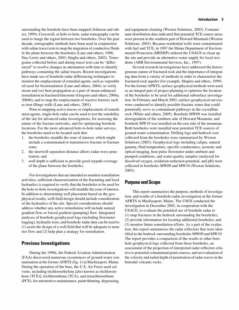
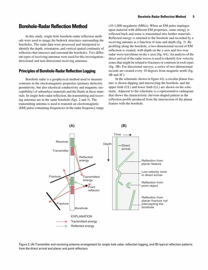
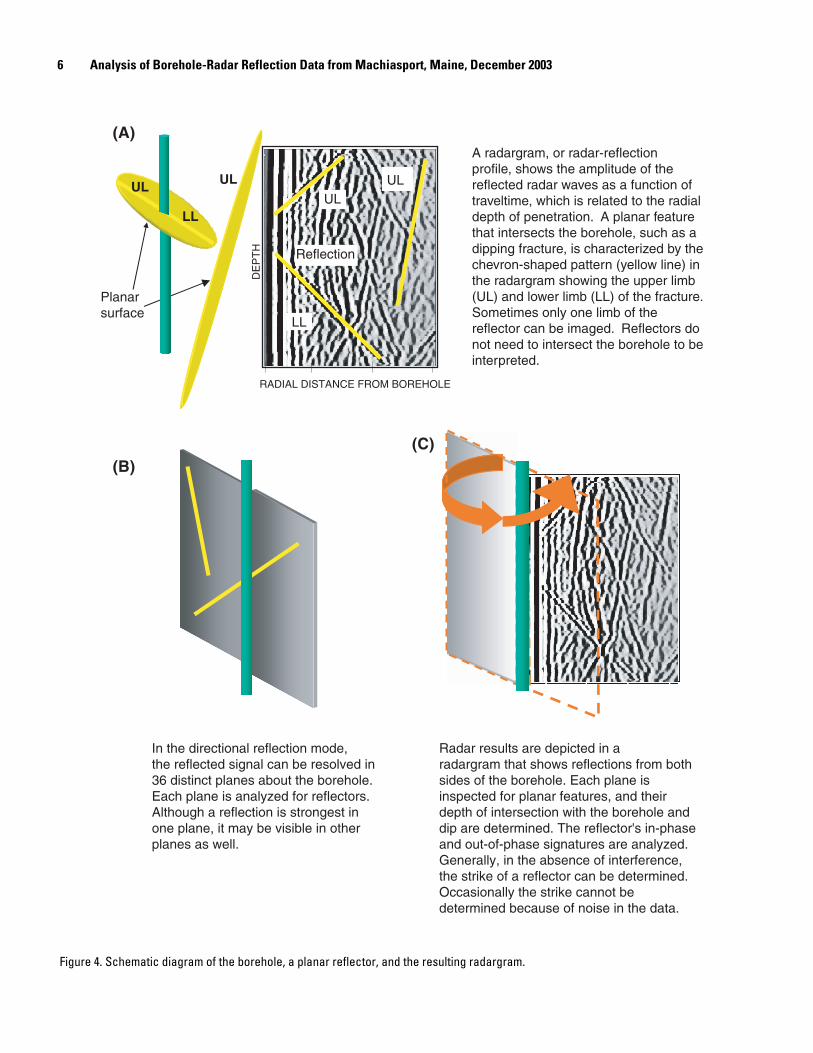
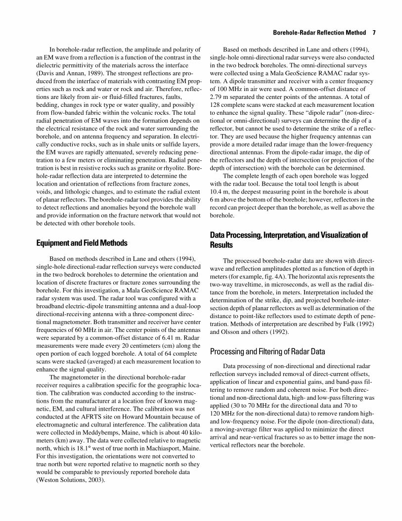
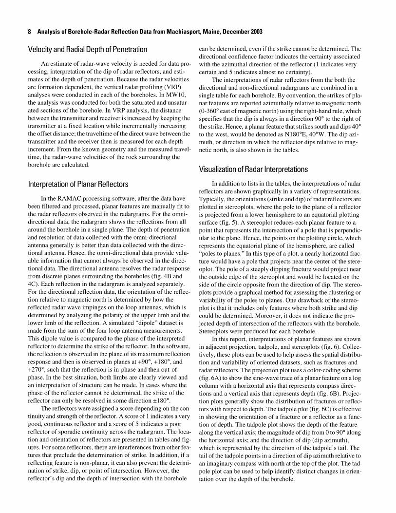
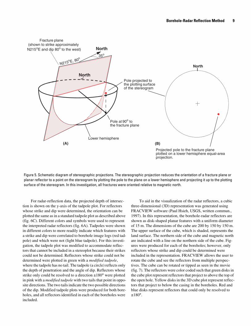
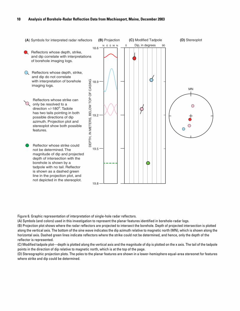

12 Analysis of Borehole-Radar Reflection Data from Machiasport Maine December 2003
Intersection of planar reflector projected to land surface (red)
Borehole
Extension ofreflection planeto land surface
Planar reflectorat depth
Land surface
0 5 10 15 20 METERS
0 20 40 60 FEET
LL
UL
Borehole
MagneticNorth
TrueNorth
(B)
(A)
Figure 8 Schematic diagram showing radar reflectors projected (A) to the land surface in a block diagram and (B) in map view For this interpretation the intersection of the plane with the land surface was set at 20 meters A solid line was used for reflectors where the strike and dip could be resolved and two dashed lines were used to represent the strike of the line for reflectors that could only be resolved to plusmn180deg
Data from Boreholes at the Bucks Harbor Site 13
Data from Boreholes at the Bucks Harbor Site
For this investigation borehole-geophysical logging was conducted in two bedrock boreholes MW09 and MW10 from December 9-11 2003 The boreholes are approximately 10 cm in diameter and completed to depths of 357 and 602 m (about 120 and 200 feet) respectively below land surface Information on borehole construction and location is provided in table 1
Conventional Borehole-Geophysical Logs
A complete suite of conventional borehole-geophysical logs was collected in both of the bedrock boreholes as a part of an earlier investigation to evaluate the lithology fracturing and hydraulics in boreholes at the AFRTS site (Weston Solutions 2003) Natural gamma EM induction normal resistivity spon-taneous potential and single-point resistance logs were used to determine properties of the geologic formation Mechanical cal-iper acoustic televiewer (ATV) and optical televiewer (OTV) logs were used to identify the location and orientation of frac-tures that intersect the borehole Fluid properties of the aquifer were determined using the fluid-logging tool which measures the specific conductance temperature pH oxidation-reduction potential and percent oxygen of the water in the borehole col-umn The heat-pulse flowmeter was used to measure vertical flow as low as 004 liters per minute (Lmin) in the borehole and to determine the location of inflow and outflow locations under pumping and ambient conditions In conjunction with the mea-sured fluid properties the heat-pulse flowmeter data were used
to identify hydraulically active fractures that intersect the bore-hole Where appropriate the results from the conventional logs are discussed in order to provide an integrated interpretation of the radar logs
Borehole deviation which was collected concurrently with ATV images is shown in a radial plot for each borehole The center of the plot represents the borehole location at the top of casing In the radial plot the borehole location is plotted as a function of depth with respect to true north In addition a cross-sectional plot of the borehole deviation is provided for a selected azimuthal direction typically the direction in which the borehole deviates Although the magnitude of the deviation for the boreholes generally was small the data were used to correct the orientations of the features observed in the boreholes to account for the borehole inclination Deviation data are critical for any hole-to-hole or surface-to-borehole radar investigations because small changes in distance can have a large impact on computed velocity (Day-Lewis and others 2003)
Integrated Analysis of Borehole-Radar Reflection Logs Geophysical Logs and Hydraulic Data
Detailed interpretations of directional and non-directional radar data are provided for boreholes MW09 and MW10 In addition an integrated interpretation of the radar data along with the borehole-imaging data is reported in the following sec-tion
Table 1 Construction of boreholes at the former Air Force Tracking Station area at the Bucks Harbor site Machiasport Maine
[Distances are in meters]
Borehole name Date drilled
Height of casing above land surface
Casing material
Depth of casing below land surface
Elevation of land surface
Total depth below land
surface
Depth of overburden
from drilling log1
1Information from drilling logs (Weston Solutions 2003)
MW09 6222003 088 steel 274 5961 3569 076
MW10 6202003 081 steel 579 7445 6015 396
14 Analysis of Borehole-Radar Reflection Data from Machiasport Maine December 2003
Borehole MW09
Location and construction Borehole MW09 is located on Howard Mountain off of the paved access road behind the parking lot and about 50 m southwest from the former location of Building 501 where TCE was reportedly used (fig 1) (Weston Solutions 2003) Borehole MW09 is a 10-cm diameter borehole drilled using air-hammer rotary methods Steel casing was set to 274 m to prevent flow between the unconsolidated sediments and the bedrock The top of bedrock was reported as 076 m below land surface (Weston Solutions 2003) Below the steel casing MW09 is open to a depth of 3569 m below land surface The borehole location was selected to evaluate subsur-face structures and the depths of radar penetration in the rhyolite vitrophyre and mafic gabbro rock units and to identify and delineate fractures capable of transporting ground-water con-tamination in the area of Building 501
MW09 deviates about 17 m towards the east (fig 9) The open-hole ambient water level was 238 m below land surface on December 9 2003 Borehole-radar data were collected rela-tive to top of casing and were corrected in post processing to land surface which is 088 m below the top of steel casing
Lithologic and fracture characterization Borehole MW09 intersects rhyolitic flow-banded vitrophyre and auto-breccia and a more mafic unit at depth The gamma electro-magnetic induction and ATV logs indicate a change in bedrock at a depth of about 23 m below land surface The logs show a reduction in natural gamma emissions and a small increase in conductivity below a depth of 23 m These emissions (about 50 counts per second) were similar to the emissions from the bedrock at the bottom of MW14 a borehole about 25 km north-northeast of the field site that was cored and interpreted as gab-bro (Weston Solutions 2003) The ATV also showed a change in the amplitude of the reflected wave in borehole MW09 at this depth and it appeared to stay uniform to the bottom of the bore-hole Collectively these changes are all consistent with a change in rock type as noted in the drilling records
The fractures identified in ATV logs in MW09 show a wide variation in strike and dip at shallow to steep angles The majority of features in the ATV log however are steeply dip-ping (greater than 50deg from horizontal) The depths and orienta-tions of all fractures identified in the ATV logs of MW09 are listed in table 2 (Weston Solutions 2003) Features that were
observed on both the amplitude plot and the transit time plot of the ATV logs were described as ldquoopen featuresrdquo All other fea-tures were designated as ldquoless-open featuresrdquo Stereoplots for MW09 show some clustering of the poles to planes of fractures as interpreted in ATV logs (fig 10) The more prominent open features in the ATV log (shown in red) tend to strike east and dip to the south and some strike west and dip to the north The less prominent minor features show more variability in orien-tation The minor features (shown in light blue) strike west and dip over a range of angles to the south and strike east and dip over a range of angles to the north Almost all other features in the borehole are steeply dipping and strike over a range from south to west and dip west to north The upper rhyolite vitro-phyre shows higher density of fracturing than the lower more mafic unit
Ambient downflow and upflow was measured in the bore-hole with the fracture at 231 m receiving the flow within the borehole Under ambient conditions water entered the borehole at 83 m and flowed downward and concurrently entered the borehole at the fracture at 335 m and flowed upward exiting at 231 m below land surface Under pumping conditions all inflow occurred between the bottom of casing and 46 m below land surface The specific conductance percent oxygen and pH logs indicated that the fracture at 23 m is hydraulically active which supports the interpretation of the other logs
Velocity and radial penetration distance in MW09 For borehole MW09 VRP analyses indicated there are two very dif-ferent rock types over the length of the borehole thus two dif-ferent velocities were used for the interpretation For reflectors identified in the radar image above 22 m below land surface a velocity of 125 meters per microseconds (mμs) was used For reflectors identified below 22 m a velocity of 114 mμs was used In MW09 the radial penetration distance of the direc-tional tool was 22 m whereas the radial penetration distance of the non-directional tool was 18 m from the borehole
Data from Boreholes at the Bucks Harbor Site 15
0˚15˚
30˚
45˚
60˚
75˚
90˚
105˚
120˚
135˚
150˚
165˚180˚
195˚
210˚
225˚
240˚
255˚
285˚
300˚
315˚
330˚
345˚
270˚
TN
05 10 15-05-10-15
-05
-10
-15
05
10
15
MW09 deviation
50 m
00 05 10 15 20 25
OFFSET IN METERS ALONG BEARING N100˚E
3
6
9
12
15
18
21
24
27
30
33
36
39
MW09 deviation
50 m
DE
PT
H I
N M
ET
ER
S B
ELO
W T
OP
OF
CA
SIN
G
MN
(A)
(B)
Figure 9 Borehole deviation logs for borehole MW09 in Machiasport Maine (A) Radial deviation plot in 5-meter depth increments (B) Cross-sectional view of borehole deviation in meters along a bearing of N100degE which is shown as a blue line in the radial plot [TN true north MN magnetic north]
16 Analysis of Borehole-Radar Reflection Data from Machiasport Maine December 2003
DE
PT
H I
N M
ET
ER
S B
ELO
W L
AN
D S
UR
FA
CE
STEREOPLOTTADPOLE PLOT
4
6
8
10
12
14
16
18
20
22
24
26
28
30
32
34
36
DEGREES DIP0 90N E S W N
PROJECTION
Indicates less-open featuresidentified in ATV logs
Indicates open featuresidentified in ATV logs
MN
EXPLANATION
Figure 10 Projection tadpole and stereoplot of features interpreted in the acoustic televiewer (ATV) log for borehole MW09 in Machiasport Maine Interpretations of ATV logs are from Weston Solutions (2003) All orientations are relative to magnetic north (MN)
Data from Boreholes at the Bucks Harbor Site 17
Table 2 Summary of acoustic televiewer data from borehole MW09 in Machiasport Maine
[Data modified and reinterpreted from Weston Solutions 2003]
Depth in meters below land surface Dip azimuth Strike1 Dip1 Description
33 173 83 59 less-open feature 37 336 246 78 less-open feature 42 344 254 86 less-open feature 46 58 328 8 open feature 47 26 296 83 less-open feature 47 280 190 69 less-open feature 53 31 301 84 less-open feature 54 331 241 70 less-open feature 56 335 245 84 less-open feature 59 332 242 77 less-open feature 62 32 302 78 less-open feature 63 243 153 83 less-open feature 65 339 249 81 less-open feature 69 337 247 79 less-open feature 70 335 245 81 less-open feature 73 31 301 77 less-open feature 77 334 244 81 less-open feature 77 83 353 74 less-open feature 83 332 242 83 less-open feature 85 339 249 83 open feature 85 355 265 68 less-open feature102 34 304 80 less-open feature105 36 306 77 less-open feature111 93 3 80 less-open feature118 303 213 86 less-open feature119 293 203 83 less-open feature122 147 57 61 less-open feature122 158 68 61 open feature127 322 232 74 less-open feature132 316 226 81 less-open feature140 322 232 67 less-open feature145 293 203 81 less-open feature146 189 99 82 less-open feature153 194 104 74 less-open feature154 279 189 77 less-open feature155 203 113 73 less-open feature155 211 121 84 less-open feature159 296 206 80 less-open feature159 338 248 79 less-open feature162 10 280 66 less-open feature163 5 275 72 less-open feature165 37 307 48 less-open feature165 338 248 83 less-open feature174 160 70 81 less-open feature180 169 79 84 open feature183 174 84 84 open feature184 178 88 83 less-open feature190 172 82 79 less-open feature196 25 295 82 less-open feature197 31 301 80 less-open feature
18 Analysis of Borehole-Radar Reflection Data from Machiasport Maine December 2003
208 57 327 34 less-open feature209 336 246 79 less-open feature219 333 243 81 less-open feature223 86 356 28 less-open feature225 48 318 33 less-open feature228 264 174 72 less-open feature229 292 202 73 open feature231 284 194 80 open feature236 206 116 51 less-open feature236 156 66 70 less-open feature236 30 300 32 less-open feature239 21 291 41 less-open feature245 9 279 54 less-open feature248 170 80 59 less-open feature248 181 91 56 less-open feature249 174 84 48 less-open feature250 159 69 27 less-open feature255 177 87 16 less-open feature261 7 277 70 less-open feature262 168 78 70 less-open feature264 8 278 73 open feature264 140 50 30 less-open feature265 176 86 58 less-open feature267 8 278 80 less-open feature270 68 338 25 less-open feature273 181 91 65 less-open feature278 261 171 70 less-open feature280 292 202 76 less-open feature281 282 192 79 less-open feature285 1 271 86 less-open feature289 67 337 75 less-open feature289 45 315 34 less-open feature290 346 256 19 less-open feature294 357 267 24 less-open feature294 179 89 36 less-open feature298 176 86 71 less-open feature304 270 180 85 less-open feature307 6 276 82 less-open feature308 277 187 85 less-open feature311 169 79 75 less-open feature312 290 200 75 less-open feature316 124 34 13 less-open feature320 308 218 85 less-open feature323 272 182 88 less-open feature324 270 180 88 open feature326 273 183 88 less-open feature330 281 191 84 less-open feature333 103 13 12 less-open feature334 283 193 83 less-open feature335 278 188 84 less-open feature
Table 2 Summary of acoustic televiewer data from borehole MW09 in Machiasport Maine mdashContinued
[Data modified and reinterpreted from Weston Solutions 2003]
Depth in meters below land surface Dip azimuth Strike1 Dip1 Description
Data from Boreholes at the Bucks Harbor Site 19
336 277 187 85 less-open feature339 279 189 87 less-open feature340 188 98 19 less-open feature341 275 185 87 less-open feature342 267 177 86 less-open feature345 275 185 88 less-open feature357 178 88 45 less-open feature358 271 181 87 less-open feature359 180 90 61 less-open feature
1Strike and dip are presented in the right-hand rule where the strike is in degrees east of magnetic north and the dip direction is to the right of the strike
Table 2 Summary of acoustic televiewer data from borehole MW09 in Machiasport Maine mdashContinued
[Data modified and reinterpreted from Weston Solutions 2003]
Depth in meters below land surface Dip azimuth Strike1 Dip1 Description
Borehole-radar reflectors in MW09 The highest ampli-tude radar reflectors in the radargram (fig 11) project to inter-sect the borehole near or above the top of the borehole These reflectors are high-resolution and strong features that project to the line of the borehole at -396 -95 -07 and ndash03 m below land surface (table 3) It is unlikely that these features extend as far down in depth as indicated on the radargram rather it is thought this is an artifact of the image Because of strong inter-ference the strikes of these features were difficult to determine Moreover from the data it was unclear which side of the bore-hole these features are on and where they might project which might be important for understanding the site The features that project to intersect the borehole at 45 m strike about N240deg E and dip steeply about 70deg to the northwest In general the loca-tions of the poles to the reflector planes (fig 12) are consistent with the clusters identified in the stereoplots for the ATV data (fig 10) Because there were relatively few radar reflectors whose strike and dip could be determined or because of the vari-ability of the reflector orientations the poles to reflector planes form only ldquoweakrdquo clusters at best (fig 12) The radar reflectors in MW09 strike southwest and dip at a variety of angles to the northwest and strike east-northeast and dip south-southeast
A total of 45 reflectors were interpreted from the borehole-radar reflection data collected in MW09 (fig 11) Five of the reflectors correlate to features interpreted in the ATV log for MW09 and are shown in red in the projection and tadpole plots for MW09 (fig 12) Some of these features were very subtle in the radargram but location and orientation compare well to the ATV data Seven reflectors (shown in light blue) are projected to intersect the borehole in the casing or above the land surface however not all of these were shown in the tadpole plot which was terminated at 50 m above the land surface Nine other reflectors that do not correlate with the ATV are projected to intersect below the bottom of the borehole with the deepest reflector projected to a depth of about 90 m These reflectors are also shown in light blue in figure 12 Five reflectors had strike
values that could be resolved only to plusmn180deg They were shown as pink tadpoles with two tails and with both possible poles to the planes in the stereoplot (fig 12)
Although the numbers of poles in the stereoplot were sparse more radar interpretations were displayed in the projec-tion and tadpole plots by including features whose strike and dip direction could not be resolved The projection tadpole and stereoplots for MW09 indicate there were many reflectors whose strike could not be determined The vertical distribution of tadpoles shows there are numerous reflectors that project to the open part of the borehole There are more radar reflectors that project to intersect the upper part of the borehole above 23 m where the change in lithology was observed The distribu-tion of tadpoles along the horizontal axis indicates that many of these features are steeply dipping which is consistent with the features observed in the ATV logs for this borehole
In radargrams large water-filled fractures are often identi-fied by an increase in the attenuation of radar signals and a decrease in the velocity of radar-wave propagation (Chapman and Lane 1996) Two fractures that were observed in MW09 in the ATV log at 457 and 3353 m below land surface were iden-tified as transmissive with the heat-pulse flowmeter These fea-tures were also identified in the borehole-radar data at about the same depths however no change in the attenuation was associ-ated with these features A feature in the ATV log at 23 m which has been interpreted as the transmissive zone was receiv-ing water under ambient conditions and appeared to have a small decrease in the velocity of radar waves Because the radar velocity remained constant in the lower part of the borehole it is likely that the decrease in radar velocity is associated with the change in the rock type that occurs at 23 m The decrease in velocity is minor about 11 mμs however there was no real change in attenuation associated with the change in rock type at about 23 m below land surface
20 Analysis of Borehole-Radar Reflection Data from Machiasport Maine December 2003
00 02 04 06
TWO-WAY TRAVELTIME IN MICROSECONDS
0 10 20 30
RADIAL DISTANCE IN METERS
10
20
30
DE
PT
H I
N M
ET
ER
S B
ELO
W L
AN
D S
UR
FAC
E
- 1000 0 - 500 0
- 250 0- 100 0 - 50 0
- 25 0- 10 0
010 025 0
50 0100 0250 0
500 01000 0
AMPLITUDEIN
MICROVOLTS
Figure 11 Processed 60-megahertz borehole-radar log from borehole MW09 in Machiasport Maine
Data from Boreholes at the Bucks Harbor Site 21
-40
-30
-20
-10
0
10
20
30
40
50
60
70
80
90
Pro
ject
ed to
abo
ve b
otto
m o
f ste
el c
asin
g la
nd s
urfa
ceO
pen
bore
hole
Pro
ject
ed to
bel
ow th
e bo
ttom
of t
he b
oreh
ole
STEREOPLOTTADPOLE PLOT
DEGREES DIP0 90N E S W N
PROJECTION
DE
PT
H I
N M
ET
ER
S B
ELO
W L
AN
D S
UR
FA
CE
Reflectors whose depth strike and dip correlate with interpretations of borehole imaging logs
Reflectors whose strike can only be resolved to a direction +-180o Tadpole has two tails pointing in both possible directions of dip azimuth Projection plot and stereoplot show both possible features (in pink)
Reflector whose strike could not be determined The magnitude of dip and projected depth of intersection with the borehole is shown by a tadpole with no tail Shown as a dashed green line in the projection plot and not depicted in the stereoplot
EXPLANATION
Reflectors that do not correlate with interpretation of borehole imaging logs
MN
Figure 12 Projection modified tadpole and stereoplot for radar reflections identified in borehole MW09 in Machiasport Maine All orientations are relative to magnetic north (MN)
22 Analysis of Borehole-Radar Reflection Data from Machiasport Maine December 2003
Table 3 Summary of borehole-radar reflector data from borehole MW09 in Machiasport Maine
[-- indicates strike could not be determined NA indicates not applicable]
Projected depth in meters below
land surface1Dip azimuth Strike2 Dip2
Continuity factor(1=very good
5=poor)
Directional confidence factor
(1=very good 5=poor)
Correlated with borehole
imaging logs3
-1394 290 200 82 4 4 -- -396 70 340 63 3 5 -- -285 130 40 73 4 3 -- -95 -- -- 68 3 NA -- -07 -- -- 66 3 NA -- -03 -- -- 30 1 NA -- 09 -- -- 23 2 NA -- 22 -- -- 33 3 NA -- 42 -- -- 61 2 NA -- 43 -- -- 28 3 NA -- 45 328 238 70 5 5 yes 45 331 241 70 5 4 -- 52 -- -- 65 2 NA -- 74 -- -- 49 2 NA -- 82 -- -- 61 1 NA -- 89 -- -- 59 2 NA -- 100 -- -- 10 4 NA -- 121 -- -- 45 2 NA -- 142 -- -- 39 4 NA -- 154 -- -- 51 3 NA -- 189 -- -- 53 4 NA -- 194 -- -- 48 2 NA -- 209 -- -- 49 2 NA -- 214 340 250 28 4 5 yes 216 -- -- 41 2 NA -- 223 -- -- 50 2 NA -- 227 30 300 32 4 4 yes 227 -- -- 62 4 NA -- 236 9 279 54 5 5 -- 236 -- -- 53 2 NA -- 278 -- -- 58 2 NA -- 285 303 213 7 4 4 yes 285 -- -- 61 2 NA -- 296 -- -- 42 2 NA -- 349 175 85 55 4 4 yes 350 180 90 61 4 5 -- 364 -- -- 57 3 NA -- 366 -- -- 34 3 NA -- 411 -- -- 52 2 NA -- 475 -- -- 61 3 NA -- 552 180 90 62 4 3 -- 555 180 90 67 4 4 -- 759 150 60 74 3 2 -- 788 4150330 460240 68 3 5 -- 887 426080 4170350 84 2 5 --
1Reflectors with a negative depth are projected above land surface2Strike and dip are presented in the right-hand rule where the strike is in degrees east of magnetic north and the dip
direction is to the right of the strike3Reflectors that can be correlated with features identified in the acoustic or optical televiewer logs are indicated with ldquoyesrdquo4Strike and dip azimuth cannot be uniquely determined from the data and is shown plusmn 180deg
Data from Boreholes at the Bucks Harbor Site 23
Borehole MW10
Location and construction Borehole MW10 is located south of the top of Howard Mountain near the FAA dome and within the footprint of the former Building 114 (Thompson and others 2005) This borehole contained water with measurable TCE concentrations which are thought to be from the source area in Building 114 (Weston Solutions 2003) An exposed bedrock cliff is about 10 to 15 m east-northeast and wraps around to about 100 m south-southeast of MW10 On the east-northeast side the cliff extends downward a vertical distance of about 20 m over a lateral distance of about 20 m Fractures observed in the outcrop making up the bedrock cliff were paral-lel to the major fault zone in the area which strikes northwest to the southeast Another set of nearly vertical fractures strikes normal to the fault zone In addition several sheeting fractures that are nearly parallel to the land surface impart a stair-step shape on the cliff face (James Vernon ENSR International written commun 2005)
In June 2003 MW10 was drilled with air hammer rotary methods and steel casing was set to 579 m below land surface to prevent flow between the unconsolidated sediments and the bedrock Below the steel casing MW10 is a 10-cm-diameter open hole for a total depth of 6015 m below land surface MW10 deviates gradually about 3 m towards the east over the entire length of the borehole (fig 13) Borehole-radar data were collected relative to top of casing and were corrected in post processing to land surface which is 081 m below the top of steel casing All radar reflector depths are reported relative to land surface
The open-hole ambient water level was about 3703 m below the land surface on December 10 2003 The water level has been consistently low since MW10 was drilled Because of the substantial depth to water and the amount of open hole above the water table the VRP analyses were conducted above and below the water level The radar-wave velocity of the zone above the water level was 125 mμs the velocity of the zone below the water level was 124 mμs For the interpretation of reflectors in this borehole a uniform velocity of 125 mμs was used
Lithologic and fracture characterization MW10 inter-sects flow-banded stony rhyolite with possible autobreccia Because the ATV tool has to be submerged in fluid the ATV data are limited to the bottom of the borehole below a depth of about 37 m Fracture interpretations above the water table were limited to OTV data The fractures identified in the ATV and OTV data showed some very steeply dipping features (table 4) Stereoplots show some clustering of the poles to fracture planes (fig 14) Using the fracture interpretations of Weston Solutions (2003) the stereoplots indicate the possibility of multiple frac-ture zones One cluster of poles to planes near the left edge of
the stereoplot represents reflectors that dip steeply (60deg to 80deg from horizontal) towards the east-northeast The cluster of poles to planes near the bottom edge of the stereoplot diagram repre-sents planes that dip steeply (70deg to 85deg) to the north and north-northeast Two smaller clusters of poles to planes near the top and right sides of the diagram represent features that dip steeply (approximately 70deg to 85deg degrees from horizontal) to the south-southeast and west-southwest A few poles to planes plot near the center of the stereoplot indicating nearly horizon-tal features The fracture at 468 m which was identified as transmissive by heat-pulse flowmeter logging is nearly hori-zontal
Velocity and radial penetration distance in MW10 VRP analyses indicated that a uniform velocity of 125 mμs could be used for analyses over the entire length of borehole MW10 In addition the depths of penetration were uniform above and below the water table The radial penetration distance with the directional tool was 40 m The penetration distance with the non-directional tool was 30 m from the borehole Both are near the end of the data-acquisition time window which means that if the time window were increased it may have pro-vided a deeper view into the formation however the strength of the reflectors appeared to be diminishing within the time win-dow that was used
The radargram for MW10 shows a small sample shift in the data at the depth of the water table at about 43 m (fig 15) The sample shift is related to the lower velocity and saturation conditions in the bottom of the borehole
24 Analysis of Borehole-Radar Reflection Data from Machiasport Maine December 2003
00 10 20OFFSET IN METERS ALONG BEARING N100˚ E
5
10
15
20
25
30
35
40
45
50
55
60
MW10 deviation50 m
0˚15˚
30˚
45˚
60˚
75˚
90˚
105˚
120˚
135˚
150˚
165˚180˚
195˚
210˚
225˚
240˚
255˚
285˚
300˚
315˚
330˚
345˚
270˚
TN
1 2-1-2
-1
-2
1
2
MW10 deviation50 m
MN
DE
PT
H I
N M
ET
ER
S B
ELO
W T
OP
OF
CA
SIN
G
meters
(A)
(B)
Figure 13 Borehole deviation logs for borehole MW10 in Machiasport Maine (A) Radial deviation plot in 5-meter depth increments (B) Cross-sectional view of borehole deviation in meters along a bearing of N100degE which is shown as a blue line in the radial plot [TN true north MN magnetic north]
Data from Boreholes at the Bucks Harbor Site 25
0
10
20
30
40
50
60
DE
PT
H I
N M
ET
ER
S B
ELO
W L
AN
D S
UR
FA
CE
STEREOPLOTTADPOLE PLOTDEGREES DIP0 90N E S W N
PROJECTION
Indicates less-open featuresidentified in OTV and ATV logs
Indicates open featuresidentified in OTV and ATV logs
EXPLANANTION
MN
Figure 14 Projection tadpole and stereoplot for optical televiewer (OTV) and acoustic televiewer (ATV) data collected in borehole MW10 in Machiasport Maine OTV results were used above 37 meters and ATV results were used below 37 meters All orientations are relative to magnetic north (MN)
26 Analysis of Borehole-Radar Reflection Data from Machiasport Maine December 2003
Table 4 Summary of optical and acoustic televiewer data from borehole MW10 in Machiasport Maine
[Data modified and reinterpreted from Weston Solutions 2003]
Depth in meters below land surface Dip azimuth Strike1 Dip1 Description
69 196 106 36 less-open feature
81 355 265 86 less-open feature
114 12 282 83 less-open feature
123 350 260 59 less-open feature
160 96 6 64 less-open feature
176 243 153 53 less-open feature
192 62 332 78 less-open feature
195 240 150 78 less-open feature
204 77 347 78 less-open feature
225 70 340 76 less-open feature
225 20 290 81 less-open feature
228 68 338 78 less-open feature
238 77 347 79 less-open feature
245 153 63 84 less-open feature
250 340 250 61 less-open feature
254 159 69 82 less-open feature
265 146 56 84 less-open feature
267 170 80 83 less-open feature
271 240 150 79 less-open feature
276 252 162 80 less-open feature
279 239 149 71 less-open feature
285 71 341 76 less-open feature
289 69 339 81 less-open feature
302 262 172 85 less-open feature
311 58 328 80 less-open feature
316 70 340 78 less-open feature
322 149 59 75 less-open feature
397 0 270 70 less-open feature
398 256 166 20 less-open feature
402 298 208 18 less-open feature
409 187 97 13 less-open feature
424 68 338 71 less-open feature
428 77 347 65 less-open feature
452 54 324 67 less-open feature
467 72 342 73 less-open feature
468 135 45 4 open feature
476 288 198 64 less-open feature
479 9 279 76 less-open feature
482 93 3 71 less-open feature
492 81 351 76 less-open feature
507 66 336 67 open feature
510 74 344 64 less-open feature
534 78 348 76 open feature
538 349 259 80 less-open feature
541 132 42 73 less-open feature
546 5 275 81 less-open feature
Data from Boreholes at the Bucks Harbor Site 27
550 11 281 83 open feature
556 9 279 83 less-open feature
561 6 276 83 open feature
569 1 271 83 less-open feature
572 9 279 83 less-open feature
582 12 282 84 less-open feature
583 5 275 83 less-open feature
584 6 276 84 less-open feature
593 66 336 68 less-open feature
594 7 277 85 less-open feature
597 13 283 82 less-open feature
603 13 283 83 less-open feature
607 12 282 84 less-open feature
1Strike and dip are presented in the right-hand rule where the strike is in degrees east of magnetic north and the dip direction is to the right of the strike
Table 4 Summary of optical and acoustic televiewer data from borehole MW10 in Machiasport MainemdashContinued
[Data modified and reinterpreted from Weston Solutions 2003]
Depth in meters below land surface Dip azimuth Strike1 Dip1 Description
28 Analysis of Borehole-Radar Reflection Data from Machiasport Maine December 2003
Borehole-radar reflectors in MW10 The most promi-nent and unusual feature in the radar record for MW10 (fig 15) is a slightly curved feature observed over the entire depth of the borehole It is located about 10 m from the borehole near the top of the borehole and about 20 m near the bottom of the borehole This feature roughly coincides with the location of the rock cliff face No other reflectors break this reflector indicating it is a very strong reflector A plane cannot be fit to the feature because it is an irregular (non-planar) shape The interpreted orientation of the reflector parallel to N30degE or N210degE is con-sistent with the orientation of the cliff face proximal to the bore-hole The cliff face to the south of the borehole also may be vis-ible in the radargram at a distance about 30 m from the borehole although this reflector is not as prominent as the reflection off of the cliff face to the east-northeast
A total of 53 reflectors were interpreted from the borehole-radar reflection data collected in MW10 (table 5) Twenty-four of these reflectors were observed only in the dipole (non-direc-tional) radar data (shown in green fig 16) Nine of the 53 reflectors correlate to interpreted features from the ATV logs (shown in red fig 16) Ten of the reflectors which do not cor-relate with the OTV and ATV are projected to intersect below the bottom of the borehole and 14 reflectors are projected to intersect the borehole above the open part of the borehole (in the casing or above the borehole) (fig 16) Four reflectors had strike values that could be resolved to a bearing plusmn180deg These reflectors are shown as pink tadpoles with two tails and with both possible poles to the reflection plane in the stereoplot (fig 16) Although the filtering may have removed many near vertical features from the radargram several steeply dipping reflectors were identified in the rock surrounding the borehole These steeply dipping features are consistent with the fracture pattern observed in the borehole-imaging logs which showed most of the features dipping greater than 70deg from horizontal (Weston Solutions 2003) The actual reflectors however that intersect above or below the open hole could not be observed by the ATV and OTV imaging methods The distribution of radar reflectors as displayed on the projection and tadpole plots indi-cates there is a fairly uniform distribution of reflectors over the open part of the borehole Also most of the tadpoles are on the right side of the tadpole plot indicating that many of the reflec-tors dip at angles greater than 50deg from horizontal
Logging with the heat-pulse flowmeter under pumping conditions indicated that most inflow to borehole MW10 occurs between 448 and 482 m below land surface probably from the prominent fractures at about 467 m below land surface One of the fractures at 468 m below land surface was nearly horizon-tal and the other at 467 m below land surface was nearly ver-tical (striking N342degE dipping 73degNE) A radar reflector was identified at 460 m below land surface but the strike and dip of
the radar reflector (N252degE 41degN) differ from both the nearly horizontal and the nearly vertical features observed in the bore-hole-image logs at that depth A shallow dipping reflector (at 25deg from horizontal) was identified at a depth of 483 m below land surface but the strike of the feature could not be resolved Another weak inflow zone detected from 497 to 533 m below land surface might be attributed to any one of the four fractures identified in the ATV log over that depth range The radar data showed three reflectors over that depth range however only one reflector at a depth of 497 m below land surface could be resolved in both strike and dip The orientation of the radar reflector is N229degE 59degNW whereas all four features identi-fied in the ATV log were about N340degE 68degNE Although the dip and the depth of these features have good agreement the strike differs by nearly 90deg which may indicate that the two methods did not see the same feature
A radar reflector does not necessarily indicate a transmis-sive fracture Reflections can also be the result of fluid- or air-filled fractures changes in rock type and (or) flow-banding fabric within the volcanic rocks The strongest reflections are produced at the interface of materials with highly contrasting electromagnetic properties such as rock to fluid- or air-filled fracture and rock to air In addition not all fractures identified in imaging logs and flowmeter logs as transmissive are detected with borehole radar This could be caused by interference with other reflectors and (or) insufficient contrasts to resolve a small aperture fracture
In general borehole imaging and radar-reflection logging indicate that the fracture network comprises many steeply dip-ping fractures that strike and dip in many directions The poles to planes of reflectors observed in MW10 show a wide variation in strike and dip The stereoplot for the fractures intersecting the borehole showed more clustering in strike than the stereoplot for the radar reflectors This may be because the borehole imag-ing tools allow for high-resolution sampling over very short dis-tances where properties of the aquifer tend to be similar or more spatially correlated Because borehole radar penetrates into the aquifer it potentially can map more variability over a larger sampling volume
Data from Boreholes at the Bucks Harbor Site 29
0 20 40
20
40
60
- 1000 0 - 500 0
- 250 0- 100 0 - 50 0
- 25 0- 10 0
010 025 0
50 0100 0250 0
500 01000 0
AMPLITUDEIN
MICROVOLTS
RADIAL DISTANCE IN METERS
DE
PT
H I
N M
ET
ER
S B
ELO
W L
AN
D S
UR
FAC
E
00 02 04 06
TWO-WAY TRAVELTIME IN MICROSECONDS
Figure 15 Processed 60-megahertz borehole-radar log from borehole MW10 in Machiasport Maine
30 Analysis of Borehole-Radar Reflection Data from Machiasport Maine December 2003
-80
-60
-40
-20
0
20
40
60
80
100
120
Pro
ject
ed to
abo
ve b
otto
m o
f ste
el c
asin
g la
nd s
urfa
ceO
pen
bore
hole
Pro
ject
ed b
elow
bor
ehol
e
DE
PT
H IN
ME
TE
RS
BE
LOW
LA
ND
SU
RF
AC
E
STEREOPLOTTADPOLE PLOT
DEGREES DIP0 90N E S W N
PROJECTION
Reflectors whose depth strike and dip correlate with interpretations of borehole imaging logs
Reflectors whose strike can only be resolved to a direction +-180o Tadole has two tails pointing in both possible directions of dip azimuth Projection plot and stereoplot show both possible features (in pink)
Reflector whose strike could not be determined The magnitude of dip and projected depth of intersection with the borehole is shown by a tadpole with no tail Shown as a dashed green line in the projection plot and not depicted in the stereoplot
EXPLANATION
Reflectors that do not correlate withinterpretation of borehole imaging logs
MN
Figure 16 Projection modified tadpole and stereoplot for radar reflections identified in borehole MW10 in Machiasport Maine All orientations are relative to magnetic north (MN)
Data from Boreholes at the Bucks Harbor Site 31
Table 5 Summary of borehole-radar reflector data from borehole MW10 in Machiasport Maine
[-- indicates strike could not be determined NA indicates not applicable]
Projected depth in meters below
land surface1Dip azimuth Strike2 Dip2
Continuity factor (1=very good
5=poor)
Directional confidence factor
(1=very good 5=poor)
Correlated with borehole
imaging logs3
-1931 300 210 85 3 3 ---1013 310 220 72 4 5 -- -866 260 170 76 2 2 -- -452 -- -- 60 3 NA -- -404 290 200 60 4 4 -- -260 60 330 74 3 2 -- -172 430210 4300120 52 2 5 -- -148 50 320 43 2 4 -- -61 20 290 36 3 2 -- -16 270 180 73 2 4 -- -15 220 130 61 4 3 -- 11 427090 41800 17 4 5 -- 18 350 260 29 3 2 -- 35 -- -- 52 2 NA -- 50 240 150 74 4 4 -- 69 -- -- 59 3 NA -- 74 350 260 37 3 4 -- 89 -- -- 66 3 NA -- 134 423050 4140320 59 3 5 -- 135 -- -- 54 2 NA -- 141 -- -- 66 2 NA -- 145 114 24 37 5 4 yes 159 0 270 44 4 4 -- 167 -- -- 31 4 NA yes 192 -- -- 53 3 NA -- 204 -- -- 57 2 NA -- 241 -- -- 33 4 NA yes 257 -- -- 50 3 NA -- 277 4100280 410190 48 4 5 -- 313 -- -- 52 3 NA yes 360 -- -- 62 2 NA -- 422 -- -- 51 2 NA -- 453 -- -- 52 2 NA -- 460 342 252 41 4 5 yes 474 93 3 71 4 5 yes 483 -- -- 25 3 NA -- 497 319 229 59 3 3 yes 508 -- -- 37 3 NA yes 524 -- -- 42 4 NA yes 547 100 10 53 3 5 -- 563 -- -- 76 2 NA -- 566 -- -- 48 3 NA -- 588 -- -- 40 4 NA -- 635 100 10 77 2 4 -- 670 190 100 53 4 4 -- 711 -- -- 45 3 NA -- 748 100 10 80 2 4 -- 751 -- -- 25 2 NA -- 805 -- -- 19 2 NA -- 806 50 320 63 3 3 --
32 Analysis of Borehole-Radar Reflection Data from Machiasport Maine December 2003
1025 0 270 64 4 3 -- 1087 40190 4280100 56 3 5 -- 1199 170 80 78 3 2 --
1Reflectors with a negative depth are projected above land surface2Strike and dip are presented in the right-hand rule where the strike is in degrees east of magnetic north and the
dip direction is to the right of the strike3Reflectors that can be correlated with features identified in the acoustic or optical televiewer logs are indicated with ldquoyesrdquo4Strike and dip azimuth cannot be uniquely determined from the data and is shown plusmn 180deg
Table 5 Summary of borehole-radar reflector data from borehole MW10 in Machiasport MainemdashContinued
[-- indicates strike could not be determined NA indicates not applicable]
Projected depth in meters below
land surface1Dip azimuth Strike2 Dip2
Continuity factor (1=very good
5=poor)
Directional confidence factor
(1=very good 5=poor)
Correlated with borehole
imaging logs3
Results of Borehole Radar Surveys at the Bucks Harbor Site
Box plots generated for all reflectors whose orientation could be determined in boreholes MW09 and MW10 indicate that the rock is highly fractured It was difficult however to determine an overall pattern of the reflections Box plots show-ing the more continuous single-hole borehole-radar reflectors in MW09 and MW10 are shown in figures 17 and 18 respectively Reflectors that are projected into the open borehole interval are colored yellow Reflections that project to above the top of cas-ing are colored green and reflections that could only be resolved to plusmn180deg are colored red and blue In MW09 many of the continuous reflectors strike north-south and many of these reflectors are steeply dipping (fig 17) In MW10 the continu-ous reflectors strike in numerous directions and have a wide range of dips (fig 18) There were many more continuous reflectors interpreted from MW10 than from MW09
For each borehole radar reflectors whose orientation could be determined were projected to a horizontal plane at the elevation of land surface Although these fractures are not nec-essarily this long they were projected along their orientation to intersect the bedrock surface and land surface A contaminant originating on or near land surface would infiltrate into the overburden and then would likely enter the fractures Hence the projection of these fractures relative to the known contaminant sources provides some insight into the fracture pattern in the subsurface
Single-hole reflection data for MW09 showed only a few reflectors that project toward Building 501 which is approxi-mately 50 m northeast of the borehole (fig 19) The other fea-tures observed in the radar log (and the borehole imaging logs) indicate a variety of orientations that project to the northeast east and west of the borehole The borehole-radar data from MW09 indicate that the fracture network is quite complex and interconnected and not dominated by a single fracture
For borehole MW10 several reflectors extend toward or are within the footprint of former Building 114 which is the contaminant source location (fig 20) With the reflectors pro-jected to the land surface (fig 20) the variable fracture pattern is evident The high proportion of steeply dipping fractures and the low head in MW10 indicate the possibility for downward fluid and chemical migration in this aquifer Several reflectors that intersect MW10 are projected to intersect the footprint of the former Building 501 location These data do not indicate anything about the hydraulic connections of these fractures which would have to be measured using other techniques such as straddle-packer testing or single or hole-to-hole flowmeter logging As a result additional boreholes installed at this site for aquifer characterization and (or) for remediation feasibility studies should be positioned such that they consider hydraulic gradient source area and contaminant distribution as well as fracture patterns
Results of Borehole Radar Surveys at the Bucks Harbor Site 33
Figure 17 Directional single-hole borehole-radar reflectors with a continuity factor of 1 2 3 or 4 identified from borehole MW09 in Machiasport Maine Results are presented in a 3-dimensional box plot viewed from the south Magnetic north is identified as a brown line on the back side of this figure
Figure 18 Directional single-hole borehole-radar reflectors with a continuity factor of 1 2 or 3 identified from borehole MW10 in Machiasport Maine Results are presented in a 3-dimensional box plot viewed from the south
34 Analysis of Borehole-Radar Reflection Data from Machiasport Maine December 2003
240 meters (787 feet)
from borehole
MW09
Approximate locationof former Building 501
Location ofabandoned
Building 5017
12720001271800
352300
352400
127190012717001271600
352500
352200MA
INE
STA
TE
PL
AN
E D
ISTA
NC
E N
OR
TH
IN
FE
ET
MAINE STATE PLANE DISTANCE EAST IN FEET
MagneticNorth
True North
METERS0 20
50
10 30
1000 FEET
Paved road
Base map adapted from USACE 2004State Plane NAD83 Maine East Zone 1801
Figure 19 Strike of projected reflectors in borehole-radar logs from borehole MW09 in Machiasport Maine Solid lines represent projected reflectors where strike could be determined Two dashed lines are shown for each of the possible reflectors where the strike could only be resolved in a direction plusmn180deg The reflectors are projected to a horizontal land surface at the elevation of borehole MW09 The reflectors may not extend to the land surface Former location of Building 501 is based on foundations mapped by surface- geophysical methods (Thompson and others 2005)
Results of Borehole Radar Surveys at the Bucks Harbor Site 35
Paved roadApproximate location of former Building113
Approximatelocation of former
Building114
MW10
352600
352500
352700
352800
352900
353000
1271800 1271900 1272000 1272100
MAINE STATE PLANE DISTANCE EAST IN FEET
MA
INE
STA
TE
PL
AN
E D
ISTA
NC
E N
OR
TH
IN
FE
ET
METERS
MagneticNorth
True North
Base map adapted from USACE 2004 State Plane NAD83 Maine East Zone 1801
0 20
50
10 30
1000 FEET
Figure 20 Strike of projected reflectors in borehole-radar logs from borehole MW10 in Machiasport Maine Solid lines represent projected reflectors where strike could be determined Two dashed lines are shown for each of the possible reflectors where the strike could only be resolved in a direction plusmn180deg The reflectors are projected to a horizontal land surface at the elevation of borehole MW10 The reflectors may not extend to the land surface Building locations are based on foundations mapped by surface- geophysical methods (Thompson and others 2005)
36 Analysis of Borehole-Radar Reflection Data from Machiasport Maine December 2003
Borehole Spacing for Tomography Surveys and Remediation
The results of radar surveys in boreholes MW09 and MW10 indicate good depth of radial radar penetration in the rock units on Howard Mountain suggesting that radar might be a valuable tool for future investigations of the bedrock sur-rounding the boreholes The radial penetration results can also be used to estimate a reasonable separation distance between boreholes that would permit hole-to-hole surveys In radar-reflection mode the EM wave travels to the reflector and back to the receiver Hence a radial penetration distance of 20 m indicates a two-way travel distance of 40 m For hole-to-hole radar surveys (fig 2B and 2C) in which the transmitter is in one hole and the receiver is in the other the EM wave has to travel only one way Because most raypaths in the tomographic mode (fig 2C) are longer than the distance between the boreholes a simple expression can be used to approximate the separation distance of the boreholes
S = cos 45deg x D
where
Tomographic data at angles greater than 45deg are often low amplitude contain noise and are not used in the data inversion (Day-Lewis and others 2003) Hence the 45deg-angle constraint is useful for estimating the maximum borehole separation
For this investigation the radial depth of penetration was as low as 18 to 22 m in MW09 and as high as 30 to 40 m in MW10 The computation for well spacing indicates that bore-holes could be spaced about 25 m apart near MW09 and 40 m apart near MW10 The penetrations achieved in this investiga-tion however were collected in the absence of conductive con-taminants tracers or remedial measures In order to accommo-date possible changes in fluid electrical properties owing to remediation or a tracer test a conservative interwell spacing of about 20 m or less may be appropriate at this site
For hole-to-hole tomography surveys at this site the max-imum radar response would come from the planar features that are oriented normal to the tomographic plane For monitoring remediation using borehole radar boreholes ideally would need to be spaced only 20 m apart and the tomographic plane would need to include fractures that (1) are transmissive (2) contain contamination and (3) are likely have their water chemistry altered by the remediation treatment which changes the electri-cal conductivity of the fluids in the fractures
Summary
In general fracture networks with fractures of variable ori-entations increased length and high density provide additional water storage and an increased ability to transmit water In frac-tured crystalline-rock aquifers with only a few interconnected fractures flow is dominated by and limited to the intercon-nected fractures which can cause anisotropy in the direction of ground-water flow Thus it is important to identify fracture locations and hydraulic properties to optimize the locations of boreholes prior to expanding a well field or initiating remedial activities Borehole radar can be helpful for characterizing the fracture patterns in the aquifer surrounding the borehole and in designing and assessing the source-area remediation effort and its impact on the bedrock aquifer Because the radar method can see beyond the borehole walls it can be used to help map reflec-tors for understanding the site hydrogeology locating new boreholes or locating conductive tracers or contaminants The purpose of this study was to evaluate the potential use of bore-hole radar to (1) map fractures in the bedrock surrounding the boreholes (2) provide information for locating additional bore-holes and (3) evaluate radar as a tool for monitoring source-area remediation efforts
Directional single-hole borehole-radar investigations were conducted by the USGS in cooperation with the USACE in December 2003 in Machiasport Maine Two boreholes were logged as a part of a larger ongoing Department of Defense and USACE environmental restoration program at the AFRTS site near Bucks Harbor Single-hole radar-reflection methods appeared to work well at this site the bimodal volcanic rocks propagated the signal very well
Many fractures were interpreted in the radar data collected in this study Although filtering the data removed several verti-cal features near the boreholes numerous steep to nearly verti-cal features were observed away from the boreholes Within this population of interpreted fractures no large unique fractures that might dominate flow in the bedrock were identified Inter-ference between signals from the numerous strong reflectors precluded the accurate determination of the location strike and dip of some reflectors When the results of this investigation were compared to results of previously collected borehole-geo-physical logs the overall interpretations were consistent The fractures mapped by the radar methods compare well with the borehole logging and the drilling data Collectively these data indicate that the rock underlying the Howard Mountain site is highly fractured and that the fractures are oriented in a variety of directions these are factors that greatly increase the likeli-hood of a highly interconnected fracture network Because the rock surrounding the borehole is highly fractured boreholes for monitoring or remediation would not have to be strategically placed to intersect a single transmissive fracture or fracture zone in the area surrounding the boreholes Clusters of reflec-
S is the computed distance between the boreholes and
D is the two-way radial depth of penetration from reflection mode data
Acknowledgments 37
tors surrounding the borehole could be targeted for drilling however additional information on direction of flow contami-nation and source location also would be needed to site any new boreholes Single-hole radar data collected for this investi-gation do not address whether these reflectors are fractures that can transmit large amounts of water or contaminants Addi-tional geophysical logging hydraulic testing and integrated analyses would need to be conducted to determine the hydraulic properties of and contaminant distribution in the fractures or fracture zones surrounding the boreholes
Results from boreholes MW09 and MW10 showed that 60-100 MHz radar waves can penetrate 16 to 40 m into the rock surrounding the boreholes These results indicate that a bore-hole separation of up to 20 m should support hole-to-hole radar tomography The integrated drilling and borehole-geophysical logging results indicate the vitrophyre is more fractured than the more mafic gabbroic unit and fracturing intensity is greater and more uniform near MW10 than MW09 The distribution of radar reflectors as displayed on the projection and tadpole plots indicates there is a fairly uniform distribution of reflectors over the open part of the borehole Many of the reflectors dip at angles greater than 50deg from horizontal There does not appear to be a quantifiable difference in the radar-wave penetration depths in these two formations The high proportion of steeply dipping fractures and the low head in MW10 indicate the poten-tial for downward flow and chemical migration to the aquifer
Results from this investigation indicate borehole-radar reflection can be used effectively at this site for identifying reflections in the bedrock surrounding the boreholes In addi-tion these results indicate hole-to-hole radar tomography might be effective for identifying features between boreholes If the boreholes were strategically placed such that they straddle a transmissive zone differencing tomography might be effective for imaging changes in the plane between the boreholes in response to a hydraulic stress on the system such as pumping or injection of a conductive tracer or injectate for source-area remediation Prior to initiating active tracer tests and conduct-ing differencing tomography additional characterization of the fracturing and the local hydraulics should to be conducted to verify that the boreholes will straddle a contaminated transmis-sive zone which is likely to change in response to an imposed hydraulic stress
Acknowledgments
This was work done in cooperation with the USACE New England Region under MIPR W13G8633230292 The authors would like to acknowledge the support and assistance of Drew Clemens and Robert Leitch of the USACE Additionally the authors appreciate the technical assistance of Christopher Kochiss Frederick Day-Lewis and Eric White of the USGS Finally the authors are grateful to John W Lane and Jason Sorenson for technical reviews of this work and to Sandra Coo-per for her final review of the manuscript
References Cited
ABB Environmental Services Inc 1997 Engineering evalua-tion of contamination Bucks Harbor Former Air Force Radar Tracking Station Machiasport Maine Portland Maine Environmental Services Inc 76 p
Borns HW Jr 1974 Surficial geology of the Machias quad-rangle Maine Maine Geological Survey Open File No 74-4
Chapman MJ and Lane JW Jr 1996 Use of directional borehole radar and azimuthal square-array DC resistivity methods to characterize a crystalline-bedrock aquifer in Bell RS and Cramer MH eds Symposium on the Appli-cation of Geophysics to Engineering and Environmental Problems Keystone Colorado April 28-May 2 1996 Pro-ceedings Wheat Ridge Colorado Environmental and Engi-neering Geophysical Society p 833-842
Davis JL and Annan AP 1989 Ground-penetrating radar for high-resolution mapping of soil and rock stratigraphy Geophysical Prospecting v 37 p 531-551
Day-Lewis FD Lane JW Jr Harris JM and Gorelick SM 2003 Time-lapse imaging of saline tracer tests using cross-borehole radar tomography Water Resources Research v 39 no 10 14 p 1290 doi1010292002WR001722
Falk L 1992 Directional borehole antennasmdashTheory Stock-holm Sweden Stripa Project 92-16 SKB 138 p
Gates O 1981 Bedrock geology of the Machias Columbia Falls and Great Wass Island quadrangles Maine Geological Survey Department of Conservation Open File No 81-11
Gates O and Moench RH 1981 Bimodal Silurian and Lower Devonian volcanic rock assemblages in the Machias-Eastport Area Maine US Geological Survey Professional Paper 1184 32 p map at scale 162500
Green Aaron Lane JW Jr Johnson CD Williams JH Mondazzi RA and Joesten PK 2004 Combined use of borehole geophysics and packers to site potable wells in a contaminated area in Montville Connecticut in 2004 US EPANGWA Fractured Rock ConferencemdashState of the Sci-ence and Measuring Success in Remediation Portland Maine Sept 13-15 2004 Proceedings Westerville Ohio National Ground Water Association CD-ROM p 295-307
Gregoire Colette Lane JW Jr and Joesten PK 2004a Application of borehole radar for monitoring steam-enhanced remediation of a contaminated site in fractured limestone Maine USA in Hack R Azzam R and Char-lier R eds Engineering Geology for Infrastructure Plan-ning in Europemdasha European Perspective Lecture Notes in Earth Sciences Berlin Germany Springer-Verlag p 385-392
Gregoire Colette Lane JW Jr and Joesten PK 2004b The use of borehole radar tomography to monitor a steam injec-tion pilot study in a contaminated fractured limestone in EAGE (European Association of Geoscientists and Engi-neers) Near Surface Geophysics meeting Utrecht The Neth-erlands 6-9 September 2004 Proceedings Houton The
38 Analysis of Borehole-Radar Reflection Data from Machiasport Maine December 2003
Netherlands European Association of Geoscientists and Engineers 4 p
Johnson CD Dunstan AH Mack TJ and Lane JW Jr 1999 Borehole-geophysical characterization of a fractured-bedrock aquifer Rye New Hampshire US Geological Survey Open-File Report 98-558 61 p
Johnson CD Lane JW Jr Williams JH and Haeni FP 2001 Application of geophysical methods to delineate con-tamination in fractured rock at the University of Connecticut landfill Storrs Connecticut in Symposium on the Applica-tion of Geophysics to Engineering and Environmental Prob-lems Denver Colorado March 4-7 2001 Proceedings Wheat Ridge Colorado Environmental and Engineering Geophysical Society CD-ROM
Lane JW Jr Day-Lewis FD Versteeg RJ Casey CC and Joesten PK 2004 Application of cross-borehole radar to monitor field-scale vegetable oil injection experiments for biostimulation in Symposium on the Application of Geo-physics to Engineering and Environmental Problems (SAG-EEP) Colorado Springs Colorado Feb 22-26 2004 Pro-ceedings Denver Colorado Environmental and Engineering Geophysical Society CD-ROM 20 p
Lane JW Jr Haeni FP Placzek Gary and Wright DL 1996 Use of borehole-radar methods to detect a saline tracer in fractured crystalline bedrock at Mirror Lake Grafton County New Hampshire USA in Sixth International Con-ference on Ground-Penetrating Radar (GPR96) Sendai Japan Sept 30-Oct 3 1996 Proceedings Sendai Japan Tohoku University Department of Geoscience and Technol-ogy p 185-190
Lane JW Jr Haeni FP and Williams JH 1994 Detection of bedrock fractures and lithologic changes using borehole radar at selected sites in Fifth International Conference on Ground-Penetrating Radar Kitchner Ontario Canada June 12-16 1993 Proceedings Kitchner Ontario Waterloo Center for Groundwater Research p 577-591
Lane JW Jr Joesten PK and Savoie JG 2001 Cross-hole radar scanning of two vertical permeable reactive-iron walls at the Massachusetts Military Reservation Cape Cod Massachusetts US Geological Survey Water-Resources Investigations Report 00-4145 17 p
Olsson Olle Falk Lars Forslund Olof Lundmark Lars and Sandberg Eric 1992 Borehole radar applied to the charac-terization of hydraulically conductive fracture zones in crys-talline rock Geophysical Prospecting v 40 p 109-142
Singha Kamini Binley AM Lane JW Jr and Gorelick SM 2003 Electrical imaging of tracer migration at the Massachusetts Military Reservation Cape Cod in Sympo-sium on the Application of Geophysics to Engineering and Environmental Problems San Antonio Texas April 6-10 2003 Proceedings Denver Colorado Environmental and Engineering Geophysical Society CD-ROM 11 p
Shapiro AM Hsieh PA and Haeni F P 1999 Integrating multidisciplinary investigations in the characterization of fractured rock in Morganwalp DW and Buxton HT eds US Geological Survey Toxic Substances Hydrology Program-Proceedings of the Technical Meeting Charleston South Carolina March 8-12 1999 US Geological Survey Water-Resources Investigation Report 99-4018C v 3 p 669-680
Thompson MD Miller SF and Davies WE 2005 Geo-physical investigation of the Formerly Used Defense Site ndash Machiasport Maine Argonne Illinois Energy Systems Division Argonne National Laboratory Sponsor Report 119 manuscript p
USACE (United States Army Corps of Engineers) 2004 Howard Mountain site plan prepared for the Formerly Used Defense Site Program Concord Massachusetts United States Army Corps of Engineers New England District 1 p
Weston Solutions 2003 Remedial investigation report former Bucks Harbor Air Force Radar Tracking Station Machi-asport Maine [draft September 2003 prepared for the US Army Corps of Engineers New England District] Manches-ter New Hampshire Weston Solutions 617 p
White EA Thompson MD Johnson CD Abraham JD Miller SF and Lane JW Jr 2005 Surface-geophysical investigation of a formerly used defense site Machiasport MainemdashFebruary 2003 US Geological Survey Scientific Investigation Report 2004-5099 48 p
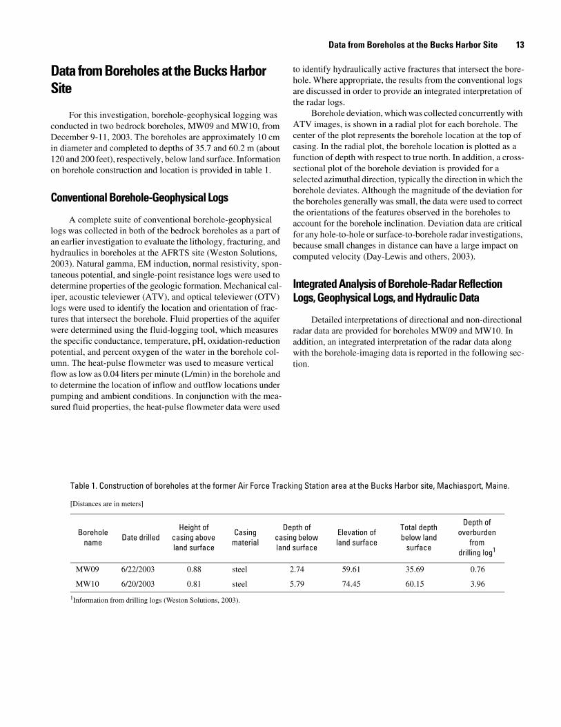
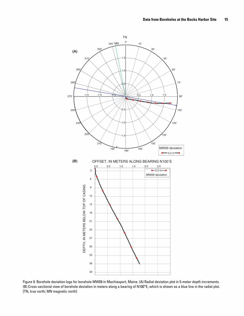
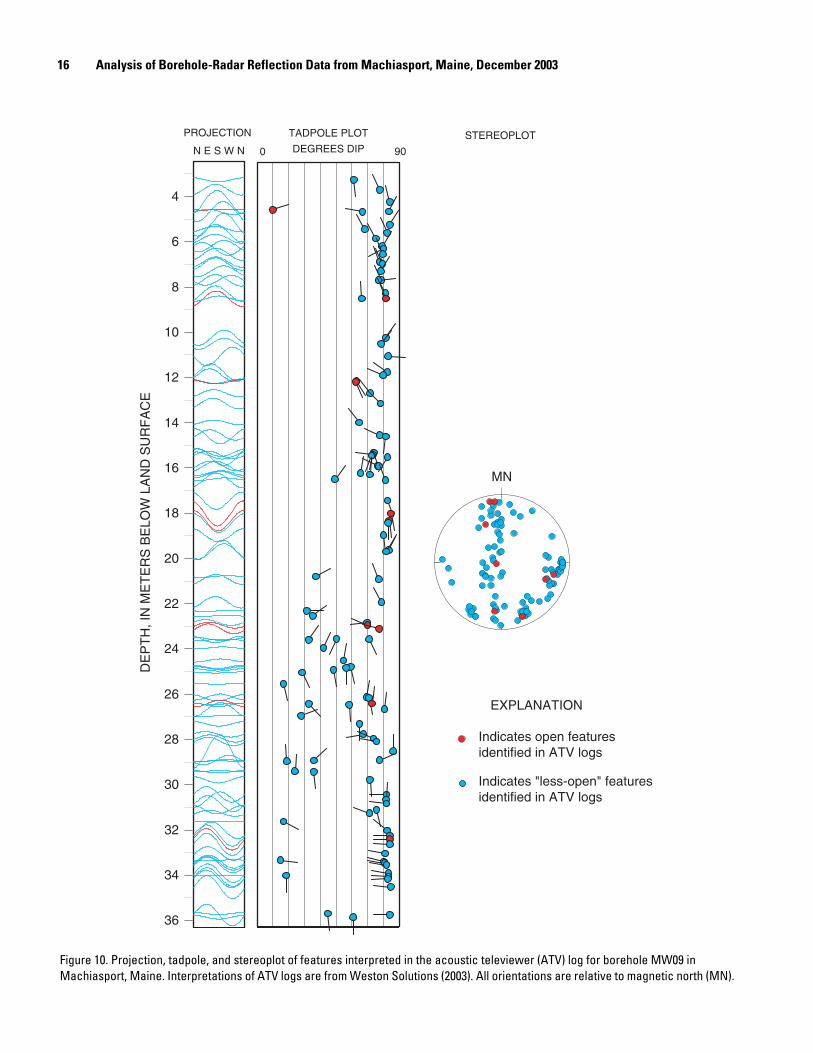
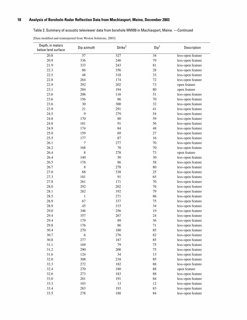
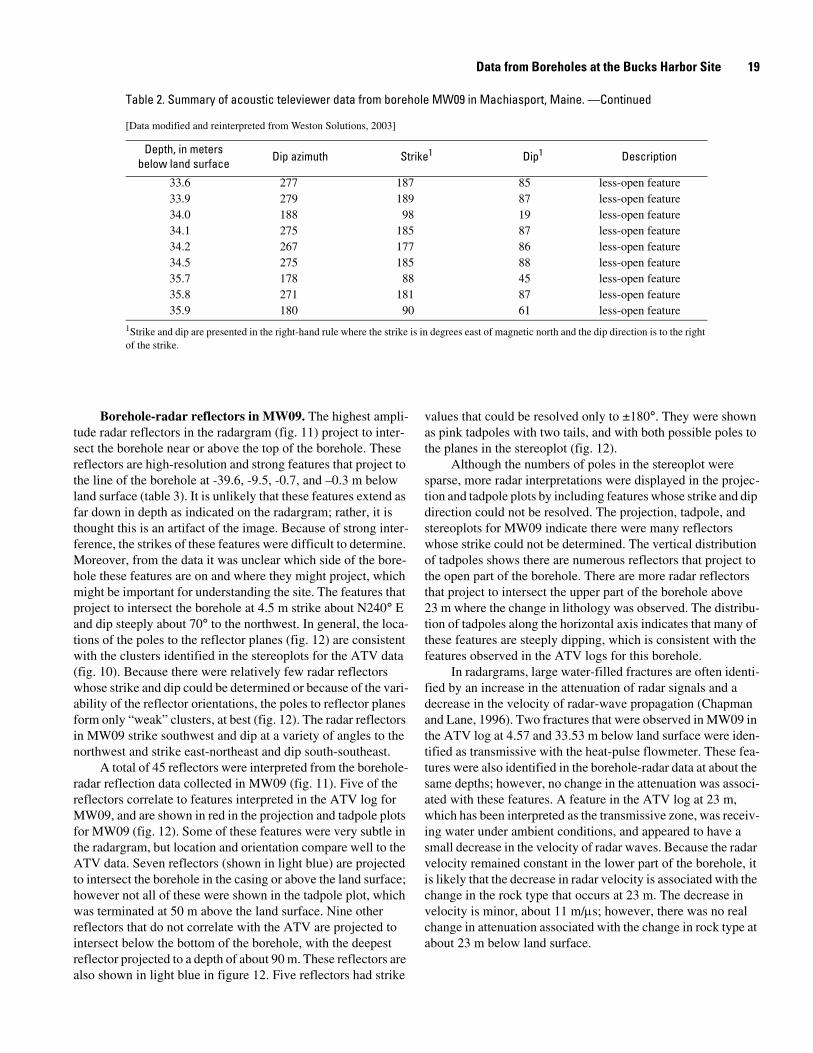
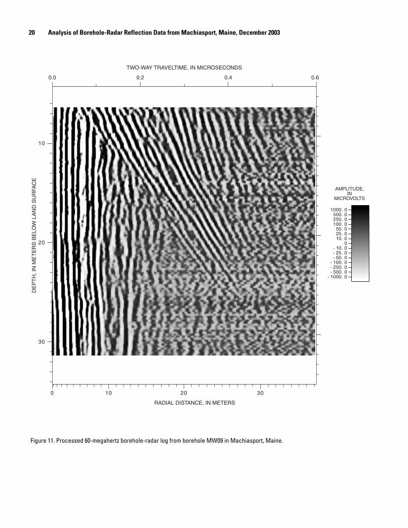
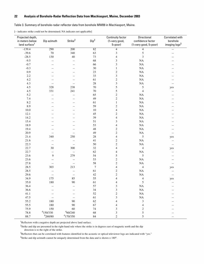
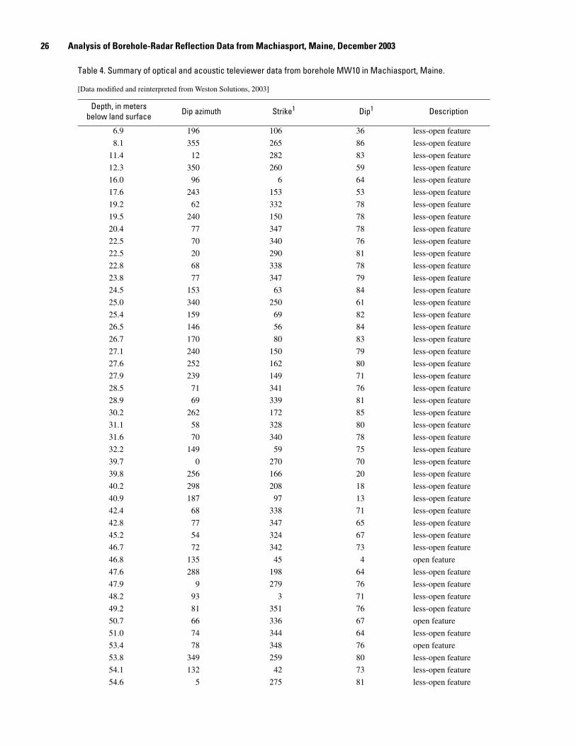
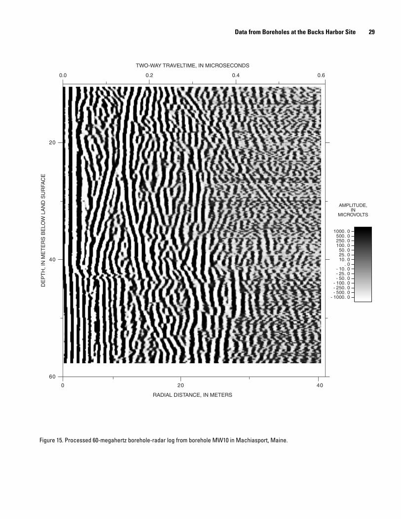
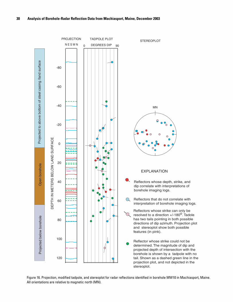
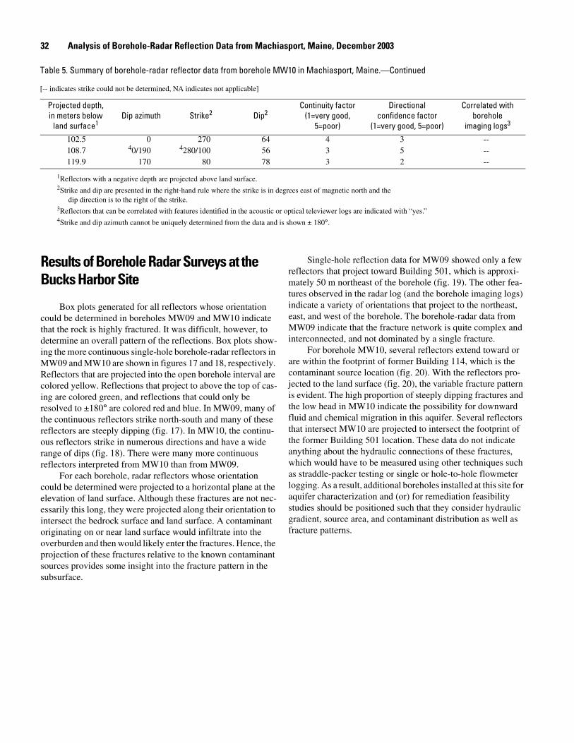
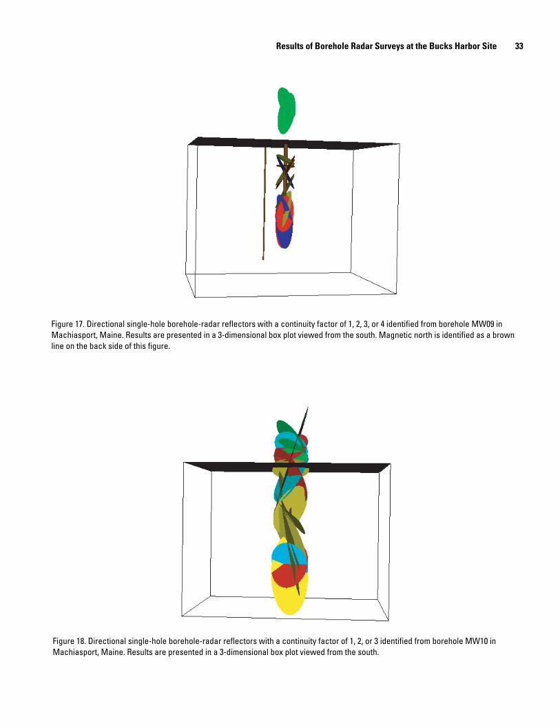
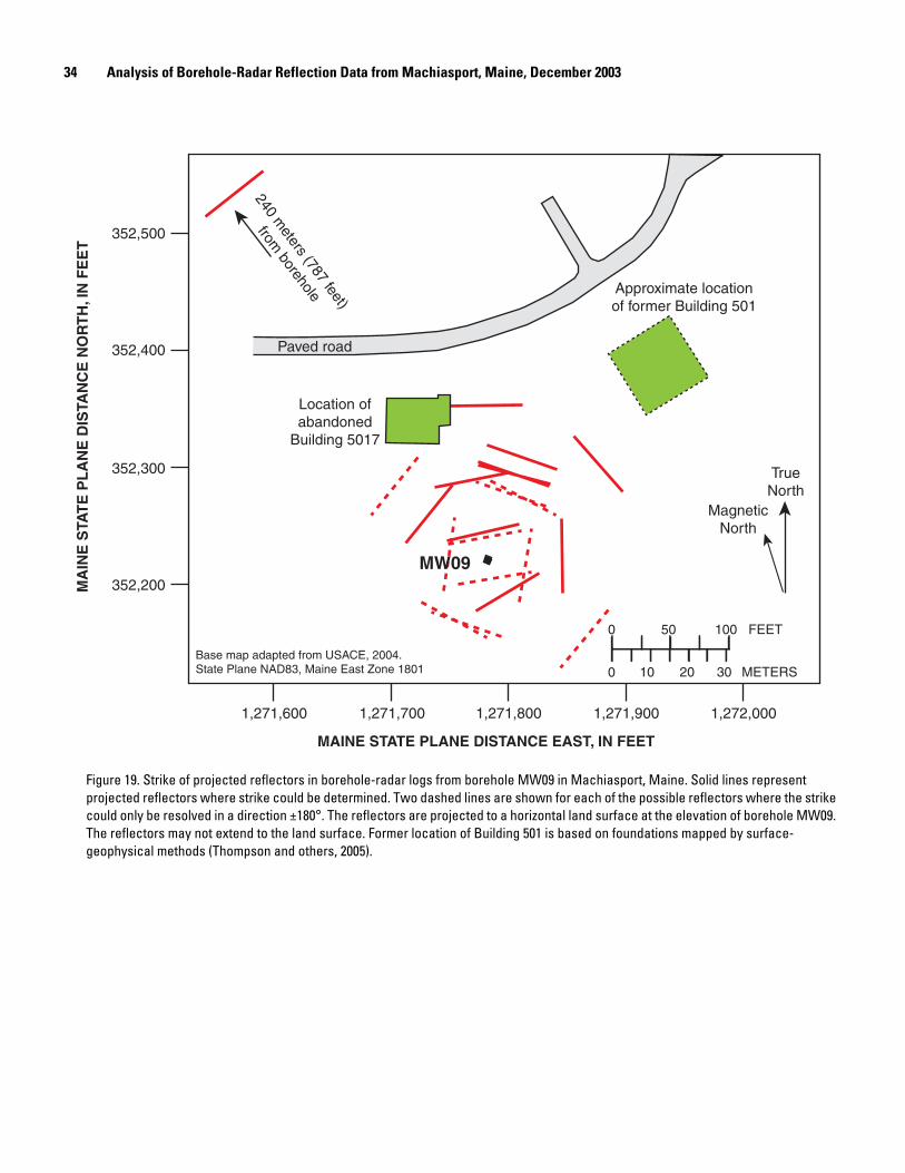


![Deep Borehole Field Test Laboratory and Borehole Testing ... · The characterization borehole (CB) is the smaller-diameter borehole (i.e., 21.6 cm [8.5”] diameter at total depth),](https://img.pdfslide.us/doc/110x75/5ebe68817151f10bcd35645a/deep-borehole-field-test-laboratory-and-borehole-testing-the-characterization.jpg)