Embed Size (px)
Citation preview
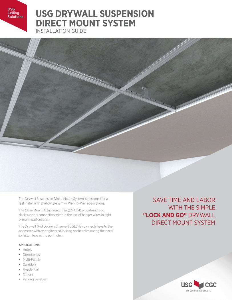
USG DRYWALL SUSPENSION DIRECT MOUNT SYSTEMINSTALLATION GUIDE
The Drywall Suspension Direct Mount System is designed for a fast install with shallow plenum or Wall-To-Wall applications.
The Close Mount Attachment Clip (CMAC-1) provides strong deck support connection without the use of hanger wires in tight plenum applications.
The Drywall Grid Locking Channel (DGLC-12) connects tees to the perimeter with an engineered locking pocket eliminating the need to fasten tees at the perimeter.
APPLICATIONS
• Hotels• Dormitories• Multi-Family• Corridors• Residential• Offices• Parking Garages
SAVE TIME AND LABOR WITH THE SIMPLE
"LOCK AND GO" DRYWALL DIRECT MOUNT SYSTEM
USG Ceiling Solutions

INSTALLATION GUIDE
DRYWALL GRID LOCKING CHANNEL
INSTALLATION
WALL-TO-WALL INSTALLATION STEPS
1. To cut channel, use tin snips to cut the upper leg, followed by the bottom leg.
Each locking pocket is spaced 8" on center within the channel. The ceiling layout may call for Wall-To-Wall Main Tees at 16" or 24" on center. Space channel appropriately along perimeter to account for required ceiling layout. Please see figure 8 for Wall-To-Wall membrane load requirements.
Wall-To-Wall Installation
a.
Fasten DGLC-12 to perimeter every 24” on center
b.
To cut channel, use tin snips to cut the upper leg,followed by the bottom leg
c.
Then bend cut section back and cut the remaining section off
a. Insert Wall-To-Wall Main Tee on one side of the perimeter. Slide bulbof tee into upper leg bulb tabs, then rotate the bottom flange underthe bottom leg tabs.
11
1. Drywall Grid Locking Channel Installation
2. Install Wall-To-Wall Main Tees (DGW26s)
b. After rotation, Main Tee bulb should fit completely inside upper legtabs and Main Tee flange should be secure under bottom leg pockettabs.
2. Then bend cut section back and cut the remaining section off.
3. Install at perimeter with fasteners every 24" on center along the DGLC-12.
Wall-To-Wall Installation
a.
Fasten DGLC-12 to perimeter every 24” on center
b.
To cut channel, use tin snips to cut the upper leg,followed by the bottom leg
c.
Then bend cut section back and cut the remaining section off
a. Insert Wall-To-Wall Main Tee on one side of the perimeter. Slide bulbof tee into upper leg bulb tabs, then rotate the bottom flange underthe bottom leg tabs.
11
1. Drywall Grid Locking Channel Installation
2. Install Wall-To-Wall Main Tees (DGW26s)
b. After rotation, Main Tee bulb should fit completely inside upper legtabs and Main Tee flange should be secure under bottom leg pockettabs.
1. Insert Wall-To-Wall Main Tee on one side of the perimeter. Slide bulb of tee into upper leg bulb tabs, then rotate the bottom flange under the bottom leg tabs.
INSTALL WALL-TO-WALL MAIN TEES (DGW26S)
2. After rotation, Main Tee bulb should fit completely inside upper leg tabs and Main Tee flange should be secure under bottom leg pocket tabs.
INSTALLATION GUIDE
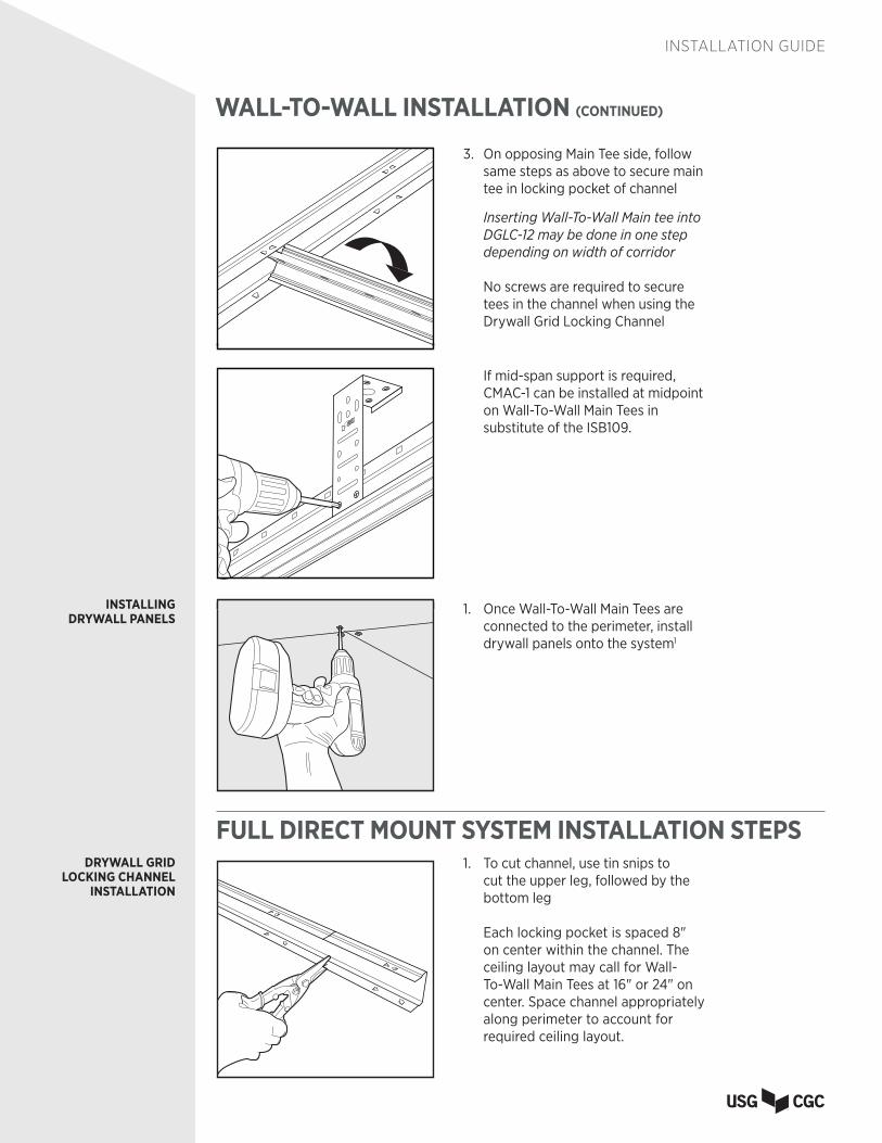
WALL-TO-WALL INSTALLATION (CONTINUED)
3. On opposing Main Tee side, follow same steps as above to secure main tee in locking pocket of channel
Inserting Wall-To-Wall Main tee into DGLC-12 may be done in one step depending on width of corridor
No screws are required to secure tees in the channel when using the Drywall Grid Locking Channel
1. Once Wall-To-Wall Main Tees are connected to the perimeter, install drywall panels onto the system1
INSTALLING DRYWALL PANELS
FULL DIRECT MOUNT SYSTEM INSTALLATION STEPSFull Direct Mount System
b. Then bend cut section back and cut the remaining section off
a. Install CMAC-1 at 48” on center along main
At least two pan head screws should be fastened through clip into the above structureSee figure 4 for CMAC-1 Detail
b. Fasten DGLW26 Main Tee to CMAC along 48" on center spacing.See Figure 1 for alternative CMAC-1 oriented install
33
a.
Drywall Grid Locking Channel Installation
To cut channel, use tin snips to cut the upper leg,followed by the bottom leg
1.
Fasten DGLC-12 to perimeter every 24” on center
c.
2. Close Mount Attachment Clip Installation
DRYWALL GRID LOCKING CHANNEL
INSTALLATION
1. To cut channel, use tin snips to cut the upper leg, followed by the bottom leg
Each locking pocket is spaced 8" on center within the channel. The ceiling layout may call for Wall-To-Wall Main Tees at 16" or 24" on center. Space channel appropriately along perimeter to account for required ceiling layout.
3. Once Wall-To-Wall Main Tees are connected to the perimeter, installdrywall panels into the system1
22
c. On opposing Main Tee side, follow same steps as above to securemain tee in locking pocket of channel
Notes:1. Please consult the Drywall Suspension System - Wall-To-Wall data sheet (AC3230)
For maximum load tables and requirements for midspan support via the ISB109.
If mid-span support is required, CMAC-1 can be installed at midpoint on Wall-To-Wall Main Tees in substitute of the ISB109.

INSTALLATION GUIDE
FULL DIRECT MOUNT SYSTEM (CONTINUED)
2. Then bend cut section back and cut the remaining section off
3. Fasten DGLC-12 to perimeter every 24” on center
DRYWALL GRID LOCKING CHANNEL
INSTALLATION
Full Direct Mount System
b. Then bend cut section back and cut the remaining section off
a. Install CMAC-1 at 48” on center along main
At least two pan head screws should be fastened through clip into the above structureSee figure 4 for CMAC-1 Detail
b. Fasten DGLW26 Main Tee to CMAC along 48" on center spacing.See Figure 1 for alternative CMAC-1 oriented install
33
a.
Drywall Grid Locking Channel Installation
To cut channel, use tin snips to cut the upper leg,followed by the bottom leg
1.
Fasten DGLC-12 to perimeter every 24” on center
c.
2. Close Mount Attachment Clip InstallationCLOSE MOUNT ATTACHMENT CLIP
INSTALLATION
Full Direct Mount System
b. Then bend cut section back and cut the remaining section off
a. Install CMAC-1 at 48” on center along main
At least two pan head screws should be fastened through clip into the above structureSee figure 4 for CMAC-1 Detail
b. Fasten DGLW26 Main Tee to CMAC along 48" on center spacing.See Figure 1 for alternative CMAC-1 oriented install
33
a.
Drywall Grid Locking Channel Installation
To cut channel, use tin snips to cut the upper leg,followed by the bottom leg
1.
Fasten DGLC-12 to perimeter every 24” on center
c.
2. Close Mount Attachment Clip Installation1. Install CMAC-1 with approved fasteners or anchors
into the above structure. These should be spaced based on membrane weight requirements (typically 48" on center). The location of CMAC-1 should be aligned with the Main Tee line.
CMAC-1 can be installed into most deck applications, including concrete. Similar to suspended hanger wires, the CMAC-1 placement should be measured for spacing requirements along deck. Additionally, CMAC-1 can be cut for specific plenum depths. See Figure 4 for CMAC-1 Detail
Full Direct Mount System
b. Then bend cut section back and cut the remaining section off
a. Install CMAC-1 at 48” on center along main
At least two pan head screws should be fastened through clip into the above structureSee figure 4 for CMAC-1 Detail
b. Fasten DGLW26 Main Tee to CMAC along 48" on center spacing.See Figure 1 for alternative CMAC-1 oriented install
33
a.
Drywall Grid Locking Channel Installation
To cut channel, use tin snips to cut the upper leg,followed by the bottom leg
1.
Fasten DGLC-12 to perimeter every 24” on center
c.
2. Close Mount Attachment Clip Installation
2. Fasten DGLW26 Main Tee to CMAC along 48" on center or otherwise prescribed deck attachment spacing.
See Figure 1 for alternative CMAC-1 oriented install
Full Direct Mount System (continued)
4. Connect Spanning Tee (DGW-DM) via cross tee clip into DGLW26
5. Connect flush end of Spanning Tee into Locking Channel
6. Install Drywall
44
DDGGLLWW--2266 48" o.c.
CCMMAACC--11 Completed Drywall Suspension Direct Mount System
See figure 5 for DGW-DM Spanning Tee detail
3. Connect flush end of Spanning Tee pockets at perimeter.
Next Spanning Tees (DGW-DM) should be spaced out according to specification (typically 24" OC) and connected into the DGLC-12 Locking Pocket.

INSTALLATION GUIDE
FULL DIRECT MOUNT SYSTEM (CONTINUED)
CLOSE MOUNT ATTACHMENT CLIP
INSTALLATION
Full Direct Mount System (continued)
4. Connect Spanning Tee (DGW-DM) via cross tee clip into DGLW26
5. Connect flush end of Spanning Tee into Locking Channel
6. Install Drywall
44
DDGGLLWW--2266 48" o.c.
CCMMAACC--11 Completed Drywall Suspension Direct Mount System
See figure 5 for DGW-DM Spanning Tee detail
E. Completed Drywall Suspension Direct Mount System
5. Install Drywall onto the systemINSTALLING DRYWALL PANELS
3. Once Wall-To-Wall Main Tees are connected to the perimeter, installdrywall panels into the system1
22
c. On opposing Main Tee side, follow same steps as above to securemain tee in locking pocket of channel
Notes:1. Please consult the Drywall Suspension System - Wall-To-Wall data sheet (AC3230)
For maximum load tables and requirements for midspan support via the ISB109.
Full Direct Mount System (continued)
4. Connect Spanning Tee (DGW-DM) via cross tee clip into DGLW26
5. Connect flush end of Spanning Tee into Locking Channel
6. Install Drywall
44
DDGGLLWW--2266 48" o.c.
CCMMAACC--11 Completed Drywall Suspension Direct Mount System
See figure 5 for DGW-DM Spanning Tee detail
4. Connect Spanning Tee (DGW-DM) via cross tee clip into DGLW26
See Figure 5 for DGW-DM Spanning Tee detail

INSTALLATION GUIDE
FIGURESSoffits with DGLC-12
5
DGLC-12 at perimeter
DGWM-24 Wall Angle
DGWM-24 Wall Angle
DGW Tee @ 24" OC
DGW Tee @ 24" OC
DGW Tee @ 24" OC
DGW Tee @ 24" OC
DGLC-12 at perimeter
DGWM-24 Wall Angle
Figure 1 - CMAC-1 Install
4
1/2"
1
1/2"
3/16"
3/16"
Figure 2 - CMAC-1 Horizontal Figure 3 - CMAC-1 Vertical
1-3/4"
Figure 4 - CMAC-1 Dimensions
Figure 6 - DGLC-12 Detail
Figure 5 - DGW-DM Spanning Tee
Cross Tee Clip at one end
Flush End at opposing side for
connection to DGLC-12
Threaded Rod Application
Pan Head Screw Locations
Figure 2 - CMAC-1 Horizontal Figure 3 - CMAC-1 VerticalFigure 1 - CMAC-1 Installation
Figure 1 - CMAC-1 Install
4
1/2"
1
1/2"
3/16"
3/16"
Figure 2 - CMAC-1 Horizontal Figure 3 - CMAC-1 Vertical
1-3/4"
Figure 4 - CMAC-1 Dimensions
Figure 6 - DGLC-12 Detail
Figure 5 - DGW-DM Spanning Tee
Cross Tee Clip at one end
Flush End at opposing side for
connection to DGLC-12
Threaded Rod Application
Pan Head Screw Locations
Figure 5 - DGW-DM Spanning Tee
Figure 1 - CMAC-1 Install
4
1/2"
1
1/2"
3/16"
3/16"
Figure 2 - CMAC-1 Horizontal Figure 3 - CMAC-1 Vertical
1-3/4"
Figure 4 - CMAC-1 Dimensions
Figure 6 - DGLC-12 Detail
Figure 5 - DGW-DM Spanning Tee
Cross Tee Clip at one end
Flush End at opposing side for
connection to DGLC-12
Threaded Rod Application
Pan Head Screw Locations
Cross Tee Clip at one end Flush end at
opposing side for connection to
DGLC-12
Figure 4 - CMAC-1 Detail
4 1 /2"
1 1/2"
3/1
3/16"
Threaded Rod Application
Pan Head Screw Locations
Close Mount Attachment Clip can be cut for varying plenum depth heights

INSTALLATION GUIDE
12'-0"
4"
8" o.c. typ.
4"
Figure 9 - DGLC-12 Spacing
12'-0"
4"
8" O.C. TYP.
4"
Figure 7 - DGLC-12 Spacing
FIGURES
Figure 1 - CMAC-1 Install
4
1/2"
1
1/2"
3/16"
3/16"
Figure 2 - CMAC-1 Horizontal Figure 3 - CMAC-1 Vertical
1-3/4"
Figure 4 - CMAC-1 Dimensions
Figure 6 - DGLC-12 Detail
Figure 5 - DGW-DM Spanning Tee
Cross Tee Clip at one end
Flush End at opposing side for
connection to DGLC-12
Threaded Rod Application
Pan Head Screw Locations
Figure 6 - DGLC-12 Detail
WALL-TO-WALLMEMBRANE LOADS
Span O.C. Spacing (in.) Maximum Load (lb./SF)
VERTICAL SUPPORT
Tee Spacing Drywall Span Support Requirement
2' 16 179.04 16" o.c. 1/2" up to 8' None
24 119.36 8'-1" to 16'*** Midspan
4' 16 22.38 16'-1" to 24'*** Two supports at 1/3 points
24 14.92 16" o.c. 5/8" up to 7'-6" None
5' 16 11.46 7'-7" to 15'*** Midspan
24 7.64 15'-1" to 22'-6"*** Two supports at 1/3 points
6' 16 6.63 24" o.c. 5/8" up to 6'-6" None
24 4.42 6'-7" to 13' Midspan
7' 16 4.18 13'-1" to 19'-6"*** Two supports at 1/3 points
24 2.78
7'-6" 16 3.40
24 2.26
8 16 2.80
24 1.86
24 14.92*
10' 16 11.46*
24 7.64*
12' 16 6.63*
24 4.42*
16' 16 2.8*
24 1.86*
24 4.42*
* Vertical support at midspan ** Two vertical supports at 1/3 point *** Spans greater than 14' require main-tee splice. Use DGSC180 splice clip or alternative splicing options described in system brochure AC3152.
INSTALLATION GUIDE
The trademarks USG, CGC, DONN, DX, DXL, FIRECODE, RADAR, IT'S YOUR WORLD. BUILD IT., the USG/CGC logo, the design elements and colors, and related marks are trademarks of USG Corporation or its affiliates.
Safety First! Follow good safety/industrial hygiene practices during installation. Wear appropriate personal protective equipment. Read SDS and literature before specification and installation.
AC5420/rev. 9-20© 2020 USG Corporation and/or its affiliates. All rights reserved.Printed in U.S.A.
Manufactured byUSG Interiors, LLC550 West Adams StreetChicago, IL 60661
NoticeThe information in this document is subject to change without notice. CGC Inc. or USG Corp. assumes no responsibility for any errors that may inadvertently appear in this document.
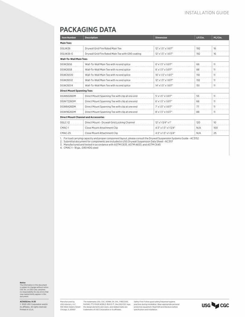
Item Number Description Dimension LF/Ctn. PC/Ctn.
Main Tees
DGLW26 Drywall Grid Fire Rated Main Tee 12' x 1.5" x 1.617" 192 16
DGLW26-E Drywall Grid Fire Rated Main Tee with G90 coating 12' x 1.5" x 1.617" 192 16
Wall-To-Wall Main Tees
DGW26S6 Wall-To-Wall Main Tee with no end splice 6' x 1.5" x 1.617" 66 11
DGW26S8 Wall-To-Wall Main Tee with no end splice 8' x 1.5" x 1.617" 88 11
DGW26S10 Wall-To-Wall Main Tee with no end splice 10' x 1.5" x 1.617" 110 11
DGW26S12 Wall-To-Wall Main Tee with no end splice 12' x 1.5" x 1.617" 132 11
DGW26S14 Wall-To-Wall Main Tee with no end splice 14' x 1.5" x 1.617" 151 11
Direct Mount Spanning Tees
DGW6026DM Direct Mount Spanning Tee with clip at one end 5' x 1.5" x 1.617" 55 11
DGW7226DM Direct Mount Spanning Tee with clip at one end 6' x 1.5" x 1.617" 66 11
DGW8426DM Direct Mount Spanning Tee with clip at one end 7' x 1.5" x 1.617" 77 11
DGW9626DM Direct Mount Spanning Tee with clip at one end 8' x 1.5" x 1.617" 88 11
Direct Mount Channel and Accessories
DGLC-12 Direct Mount - Drywall Grid Locking Channel 12' x 1-3/4" x 1" 120 10
CMAC-1 Close Mount Attachment Clip 4.5" x 1.5" x 1-3/4" N/A 100
CMAC-25 Close Mount Attachment Clip 4.5" x 1.5" x 1-3/4" N/A 25
1. For load carrying capacity and proper component layout, please consult the Drywall Suspension Systems Guide - AC31522. Submittal document for components are included in USG Drywall Suspension Data Sheet - AC31173. Manufactured and tested in accordance with ASTM C635, ASTM A653, and ASTM C6454. CMAC-1 - 18 ga., G90 HDG steel
PACKAGING DATA