Embed Size (px)
Citation preview
User's Manual
AC SERVO DRIVER
TANGO-A Series
NS SYSTEM Co., Ltd.
NS SYSTEM SinYong B/D 4F #942-6 Ingye-Dong, Paldal-Gu, Suwon-City, Kyungki-Do, Korea
Homepage : www.nssystem.co.kr TEL: 82-31-235-7492~6 FAX: 82-31-235-7497
CONTENTS
Safety Instructions 1
CHAPTER 1. FUNCTIONS AND SPECIFICATIONS 4
1-1. FEATURES AND THE PRODUCT 4
1-2. CONTROL MODE 4
1-3. STANDARD SPECIFICATIONS 5
1-4. MODEL CODE DEFINITION 9
1-4-1. NAME PLATE 9
1-4-2. MODEL CODE 9
1-5. COMBINATION WITH SERVO MOTOR 9
1-6. DIMENSIONS OF SERVO AMPLIFIER 10
1-6-1. DIMENSIONS OF BOOK TYPE1 ( TANGO-A01/A02/A04/A06 ) 10
1-6-2. DIMENSIONS OF BOOK TYPE2 ( TANGO-A08/A12/A18 ) 10
1-6-3. DIMENSIONS OF BASE MOUNT TYPE1 ( TANGO-A24/A30/A35 ) 11
1-6-4. DIMENSIONS OF BASE MOUNT TYPE2 ( TANGO-A40/A50/A75 ) 11
CHAPTER 2. INSTALLATION 12
2-1. CHECK ITEMS WHEN PRODUCT DELIVERED 12
2-2. INSTALLATION DIRECTION AND CLEARANCES 12
2-2-1. INSTALLATION OF SERVO AMPLIFIER 12
2-2-2. INSTALLATION OF SERVO MOTOR 13
2-2-3. ENVIRONMENTAL CONDITIONS 13
2-2-4. ALLOWABLE WEIGHT OF MOTOR SHAFT 13
2-2-5. AUXILIARY EQUIPMENTS AND WIRES 14
CHAPTER 3. SIGNALS AND WIRING 15
3-1. PARTS IDENTIFICATION 15
3-1-1. PARTS IDENTIFICATION OF BOOK TYPE1 / TYPE2 15
3-1-2. PARTS IDENTIFICATION OF BASE MOUNT TYPE1 / TYPE2 15
3-2. CONNECTION DIAGRAM OF SERVO AMPLIFIER 16
3-2-1. CONNECTION DIAGRAM OF BOOK TYPE1 / TYPE2 16
3-2-2. CONNECTION DIAGRAM OF BASE MOUNT TYPE1 / TYPE2 17
3-3. I/O SIGNALS OF CN1 18
3-3-1. SIGNAL LAYOUTS AND ASSIGNMENT 18
3-3-2. FORWARD/REVERSE COMMAND PULSE 18
3-3-3. INPUT SIGNALS FOR CONTROL 19
3-3-4. OUTPUT SIGNALS FOR CONTROL 20
3-3-5. ENCODER PULSE OUTPUT 21
3-3-6. ANALOG IN/OUT SIGNAL 22
3-4. MOTOR ENCODER SIGNALS OF CN3 23
3-5. SIGNALS AND WIRING OF CN4, CN5 (POWER, MOTOR, REGENERATIVE BRAKE) 23
CHAPTER 4. PARAMETER MODE 24
4-1. PARAMETER INPUT KEYS 24
4-2. PARAMETER DISPLAY AND SETTING 24
4-3. DETAILS OF PARAMETERS 25
4-3-1. PARAMETER GROUP 1 (PAR1) 25
4-3-2. PARAMETER GROUP 2 (PAR2) 31
4-3-3. PARAMETER GROUP 3 (PAR3) 37
CHAPTER 5. DISPLAY MODE 38
5-1. DISPLAY MODE SETTING 38
5-2. DETAILS OF DISPLAY MODE 38
CHAPTER 6. CHECK MODE 40
6-1. CHECK MODE SETTING 40
6-2. DETAILS OF CHECK MODE 40
CHAPTER 7. ALARM MODE 44
7-1. ALARM MODE SETTING 44
7-2. ALARM LISTS AND DETAILS 45
CHAPTER 8. OPERATION OF POSITION CONTROL 47
8-1. STANDARD CONNECTION DIAGRAM OF POSITION CONTROL 47
8-2. FUNCTIONAL BLOCK DIAGRAM AND OPERATION OF POSITION CONTROL 47
CHAPTER 9. OPERATION OF SPEED CONTROL 50
9-1. STANDARD CONNECTION DIAGRAM OF SPEED CONTROL 50
9-2. FUNCTIONAL BLOCK DIAGRAM AND OPERATION OF SPEED CONTROL 50
CHAPTER 10. OPERATION OF TORQUE CONTROL 53
10-1. STANDARD CONNECTION DIAGRAM OF TORQUE CONTROL 53
10-2. FUNCTIONAL BLOCK DIAGRAM AND OPERATION OF TORQUE CONTROL 53
CHAPTER 11. OPERATION OF INTERNAL SPEED CONTROL 55
11-1. STANDARD CONNECTION DIAGRAM OF INTERNAL SPEED CONTROL 55
11-2. FUNCTIONAL BLOCK DIAGRAM AND OPERATION OF INTERNAL SPEED CONTROL 55
CHAPTER 12. AUTO TUNING 57
12-1. SEMI-AUTO TUNING 57
12-2. FULL-AUTO TUNING 57
CHAPTER 13. SIGNAL TIMING 58
13-1. POWER ON SEQUENCE 58
13-2. SERVO ON / OFF SEQUENCE 58
13-3. BRAKE ON / OFF SEQUENCE 58
CHAPTER 14. OPTIONS 59
14-1. ENCODER AND MOTOR CABLE 59
14-2. OPTIONAL REGENERATIVE BRAKE RESISTOR 59
CHAPTER 15. MAINTENANCE AND INSPECTION 60
15-1. INSPECTION 60
15-2. LIFE 60
CHAPTER 16. SUMMARY OF LISTS 61
16-1. PARAMETER LISTS 61
16-2. ALARM LISTS 62
16-3. DISPLAY MODE LISTS 62
16-4. CHECK MODE LISTS 62
16-5. COMBINATION OF AMPLIFIERS AND MOTORS 63
16-6. PARAMETER INITIAL VALUE AT FACTORY SETTING 63
CHAPTER 17. COMMUNICATION FUNCTIONS 65
17-1. COMMUNICATION CONNECTOR (CN2) 65
17-2. COMMUNICATION SPECIFICATIONS 65
17-3. RS-232C 66
17-4. RS-422 66
17-5. PROTOCOL 67
17-5-1. DOWN LOAD 67
17-5-2. UP LOAD 67
17-6. COMMUNICATION CODES 68
APPENDIX 70
APPENDIX A. SERVO MOTOR CONFIGURATIONS 71
APPENDIX B. SERVO MOTOR CLASSIFICATION 72
APPENDIX C. SERVO MOTOR SPECIFICATIONS AND CHARACTERISTICS 73
APPENDIX C-1. KANZ/Q SERIES SERVO MOTOR SPECIFICATIONS 73
APPENDIX C-2. KAND/S SERIES SERVO MOTOR SPECIFICATIONS 74
APPENDIX C-3. KANH/F SERIES SERVO MOTOR SPECIFICATIONS 75
APPENDIX C-4. KAFX/N SERIES SERVO MOTOR SPECIFICATIONS 76
APPENDIX D. SERVO MOTOR DIMENSIONS 77
APPENDIX E. ELECTROMAGNETIC BRAKE SPECIFICATIONS 80
APPENDIX F. SHAFT END SPECIFICATIONS 81
APPENDIX G. CONNECTOR PIN ARRANGEMENT 82
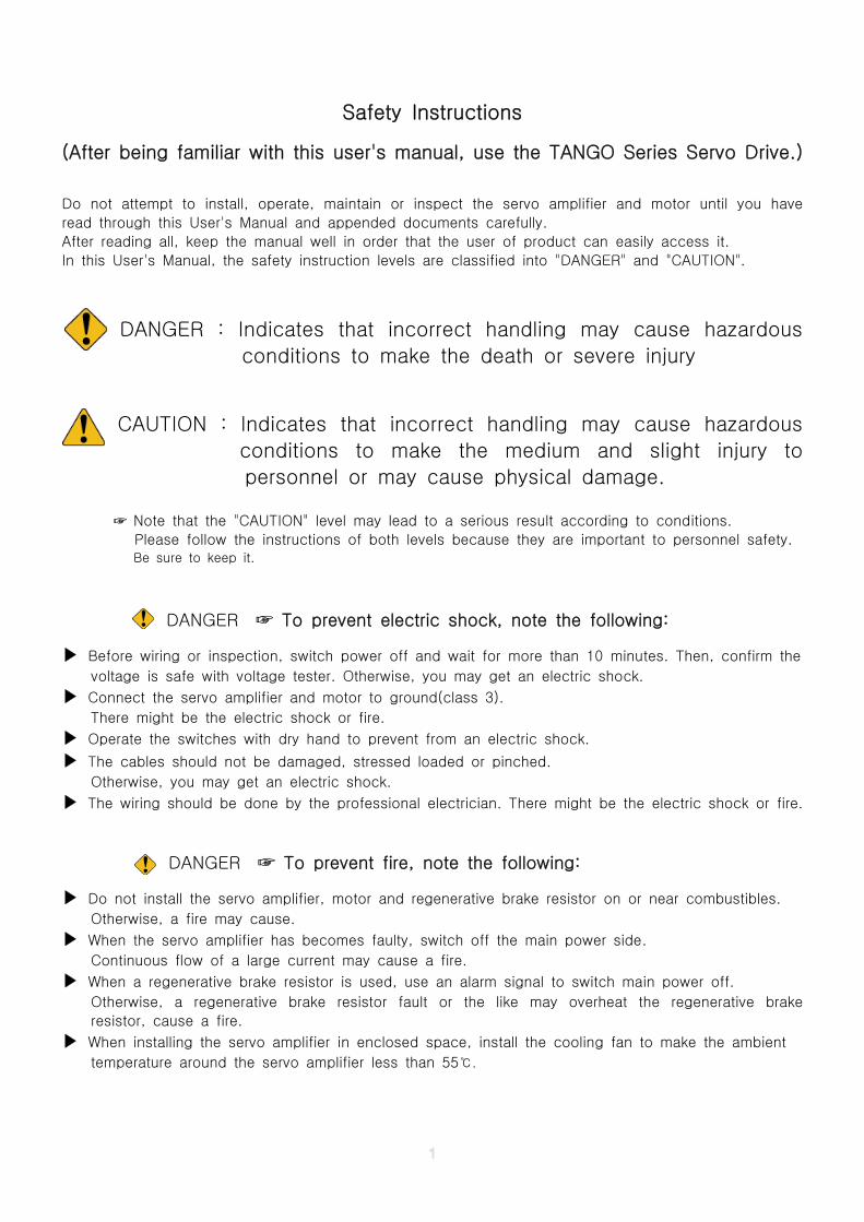
Safety Instructions
(After being familiar with this user's manual, use the TANGO Series Servo Drive.)
Do not attempt to install, operate, maintain or inspect the servo amplifier and motor until you have
read through this User's Manual and appended documents carefully.
After reading all, keep the manual well in order that the user of product can easily access it.
In this User's Manual, the safety instruction levels are classified into "DANGER" and "CAUTION".
DANGER : Indicates that incorrect handling may cause hazardous
conditions to make the death or severe injury
CAUTION : Indicates that incorrect handling may cause hazardous
conditions to make the medium and slight injury to
personnel or may cause physical damage.
☞ Note that the "CAUTION" level may lead to a serious result according to conditions.
Please follow the instructions of both levels because they are important to personnel safety.Be sure to keep it.
DANGER To prevent electric shock, note the following:☞
▶ Before wiring or inspection, switch power off and wait for more than 10 minutes. Then, confirm the
voltage is safe with voltage tester. Otherwise, you may get an electric shock.
▶ Connect the servo amplifier and motor to ground(class 3).
There might be the electric shock or fire.
▶ Operate the switches with dry hand to prevent from an electric shock.
▶ The cables should not be damaged, stressed loaded or pinched.
Otherwise, you may get an electric shock.
▶ The wiring should be done by the professional electrician. There might be the electric shock or fire.
DANGER To prevent fire, note the following:☞
▶ Do not install the servo amplifier, motor and regenerative brake resistor on or near combustibles.
Otherwise, a fire may cause.
▶ When the servo amplifier has becomes faulty, switch off the main power side.
Continuous flow of a large current may cause a fire.
▶ When a regenerative brake resistor is used, use an alarm signal to switch main power off.
Otherwise, a regenerative brake resistor fault or the like may overheat the regenerative brake
resistor, cause a fire.
▶ When installing the servo amplifier in enclosed space, install the cooling fan to make the ambient
temperature around the servo amplifier less than 55 .℃
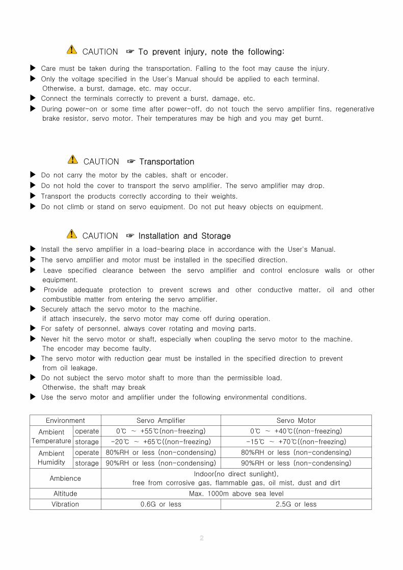
CAUTION To prevent injury, note the following:☞
▶ Care must be taken during the transportation. Falling to the foot may cause the injury.
▶ Only the voltage specified in the User's Manual should be applied to each terminal.
Otherwise, a burst, damage, etc. may occur.
▶ Connect the terminals correctly to prevent a burst, damage, etc.
▶ During power-on or some time after power-off, do not touch the servo amplifier fins, regenerative
brake resistor, servo motor. Their temperatures may be high and you may get burnt.
CAUTION Transportation☞
▶ Do not carry the motor by the cables, shaft or encoder.
▶ Do not hold the cover to transport the servo amplifier. The servo amplifier may drop.
▶ Transport the products correctly according to their weights.
▶ Do not climb or stand on servo equipment. Do not put heavy objects on equipment.
CAUTION Installation and Storage☞
▶ Install the servo amplifier in a load-bearing place in accordance with the User's Manual.
▶ The servo amplifier and motor must be installed in the specified direction.
▶ Leave specified clearance between the servo amplifier and control enclosure walls or other
equipment.
▶ Provide adequate protection to prevent screws and other conductive matter, oil and other
combustible matter from entering the servo amplifier.
▶ Securely attach the servo motor to the machine.
if attach insecurely, the servo motor may come off during operation.
▶ For safety of personnel, always cover rotating and moving parts.
▶ Never hit the servo motor or shaft, especially when coupling the servo motor to the machine.
The encoder may become faulty.
▶ The servo motor with reduction gear must be installed in the specified direction to prevent
from oil leakage.
▶ Do not subject the servo motor shaft to more than the permissible load.
Otherwise, the shaft may break
▶ Use the servo motor and amplifier under the following environmental conditions.
Environment Servo Amplifier Servo Motor
Ambient
Temperature
operate 0 +55 (non-freezing)℃ ∼ ℃ 0 +40 ((non-freezing)℃ ∼ ℃
storage -20 +65 ((non-freezing)℃ ∼ ℃ -15 +70 ((non-freezing)℃ ∼ ℃
Ambient
Humidity
operate 80%RH or less (non-condensing) 80%RH or less (non-condensing)
storage 90%RH or less (non-condensing) 90%RH or less (non-condensing)
AmbienceIndoor(no direct sunlight),
free from corrosive gas, flammable gas, oil mist, dust and dirt
Altitude Max. 1000m above sea level
Vibration 0.6G or less 2.5G or less
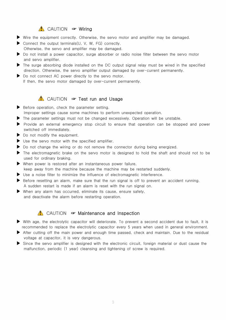
CAUTION Wiring☞
▶ Wire the equipment correctly. Otherwise, the servo motor and amplifier may be damaged.
▶ Connect the output terminals(U, V, W, FG) correctly.
Otherwise, the servo and amplifier may be damaged.
▶ Do not install a power capacitor, surge absorber or radio noise filter between the servo motor
and servo amplifier.
▶ The surge absorbing diode installed on the DC output signal relay must be wired in the specified
direction. Otherwise, the servo amplifier output damaged by over-current permanently.
▶ Do not connect AC power directly to the servo motor.
If then, the servo motor damaged by over-current permanently.
CAUTION Test run and Usage☞
▶ Before operation, check the parameter setting.
Improper settings cause some machines to perform unexpected operation.
▶ The parameter settings must not be changed excessively. Operation will be unstable.
▶ Provide an external emergency stop circuit to ensure that operation can be stopped and power
switched off immediately.
▶ Do not modify the equipment.
▶ Use the servo motor with the specified amplifier.
▶ Do not change the wiring or do not remove the connector during being energized.
▶ The electromagnetic brake on the servo motor is designed to hold the shaft and should not to be
used for ordinary braking.
▶ When power is restored after an instantaneous power failure,
keep away from the machine because the machine may be restarted suddenly.
▶ Use a noise filter to minimize the influence of electromagnetic interference.
▶ Before resetting an alarm, make sure that the run signal is off to prevent an accident running.
A sudden restart is made if an alarm is reset with the run signal on.
▶ When any alarm has occurred, eliminate its cause, ensure safety,
and deactivate the alarm before restarting operation.
CAUTION Maintenance and Inspection☞
▶ With age, the electrolytic capacitor will deteriorate. To prevent a second accident due to fault, it is
recommended to replace the electrolytic capacitor every 5 years when used in general environment.
▶ After cutting off the main power and enough time passed, check and maintain. Due to the residual
voltage at capacitor, it is very dangerous.
▶ Since the servo amplifier is designed with the electronic circuit, foreign material or dust cause the
malfunction, periodic (1 year) cleansing and tightening of screw is required.
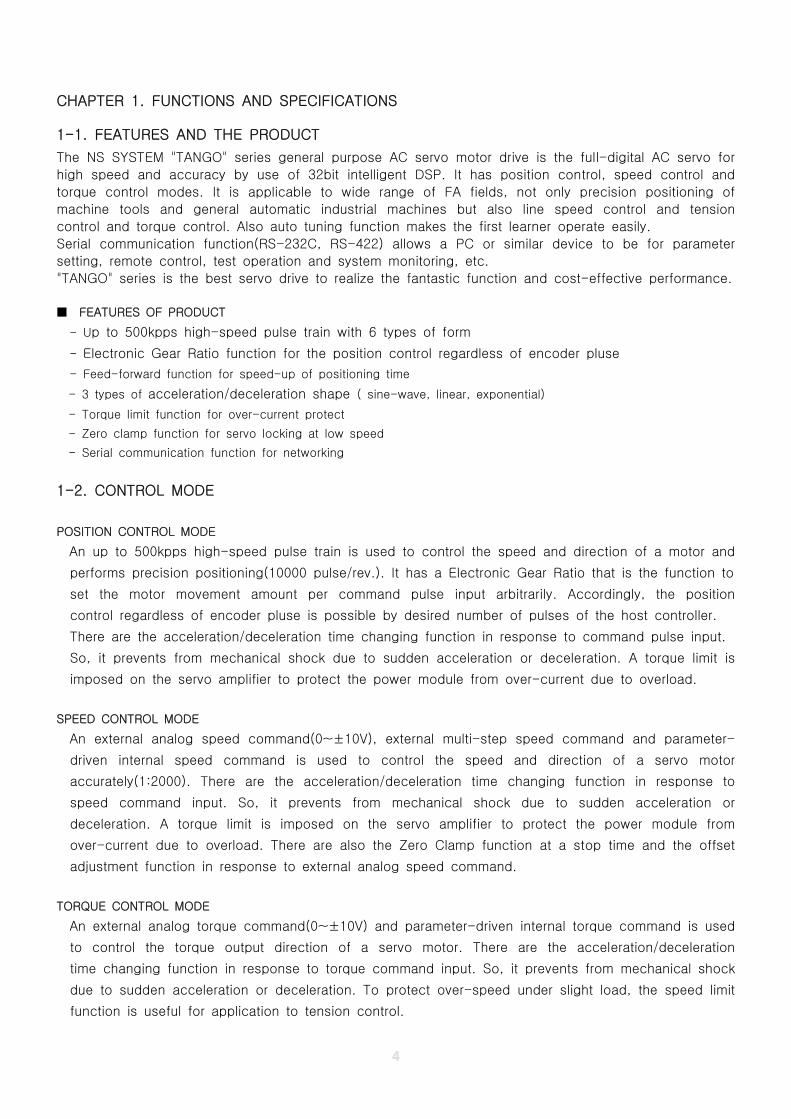
CHAPTER 1. FUNCTIONS AND SPECIFICATIONS
1-1. FEATURES AND THE PRODUCT
The NS SYSTEM "TANGO" series general purpose AC servo motor drive is the full-digital AC servo for
high speed and accuracy by use of 32bit intelligent DSP. It has position control, speed control and
torque control modes. It is applicable to wide range of FA fields, not only precision positioning of
machine tools and general automatic industrial machines but also line speed control and tension
control and torque control. Also auto tuning function makes the first learner operate easily.
Serial communication function(RS-232C, RS-422) allows a PC or similar device to be for parameter
setting, remote control, test operation and system monitoring, etc.
"TANGO" series is the best servo drive to realize the fantastic function and cost-effective performance.
■ FEATURES OF PRODUCT
- Up to 500kpps high-speed pulse train with 6 types of form
- Electronic Gear Ratio function for the position control regardless of encoder pluse
- Feed-forward function for speed-up of positioning time
- 3 types of acceleration/deceleration shape ( sine-wave, linear, exponential)
- Torque limit function for over-current protect
- Zero clamp function for servo locking at low speed
- Serial communication function for networking
1-2. CONTROL MODE
POSITION CONTROL MODE
An up to 500kpps high-speed pulse train is used to control the speed and direction of a motor and
performs precision positioning(10000 pulse/rev.). It has a Electronic Gear Ratio that is the function to
set the motor movement amount per command pulse input arbitrarily. Accordingly, the position
control regardless of encoder pluse is possible by desired number of pulses of the host controller.
There are the acceleration/deceleration time changing function in response to command pulse input.
So, it prevents from mechanical shock due to sudden acceleration or deceleration. A torque limit is
imposed on the servo amplifier to protect the power module from over-current due to overload.
SPEED CONTROL MODE
An external analog speed command(0~±10V), external multi-step speed command and parameter-
driven internal speed command is used to control the speed and direction of a servo motor
accurately(1:2000). There are the acceleration/deceleration time changing function in response to
speed command input. So, it prevents from mechanical shock due to sudden acceleration or
deceleration. A torque limit is imposed on the servo amplifier to protect the power module from
over-current due to overload. There are also the Zero Clamp function at a stop time and the offset
adjustment function in response to external analog speed command.
TORQUE CONTROL MODE
An external analog torque command(0~±10V) and parameter-driven internal torque command is used
to control the torque output direction of a servo motor. There are the acceleration/deceleration
time changing function in response to torque command input. So, it prevents from mechanical shock
due to sudden acceleration or deceleration. To protect over-speed under slight load, the speed limit
function is useful for application to tension control.
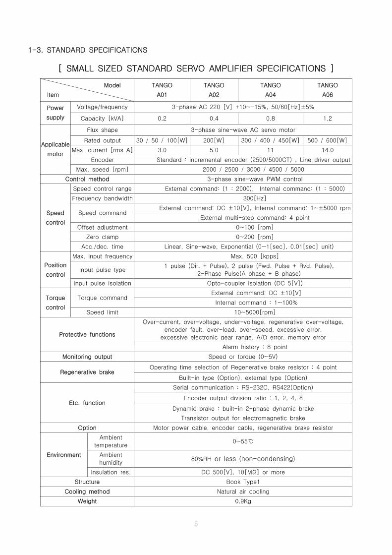
1-3. STANDARD SPECIFICATIONS
[ SMALL SIZED STANDARD SERVO AMPLIFIER SPECIFICATIONS ]
Model
Item
TANGO
A01
TANGO
A02
TANGO
A04
TANGO
A06
Power
supply
Voltage/frequency 3-phase AC 220 [V] +10~-15%, 50/60[Hz]±5%
Capacity [kVA] 0.2 0.4 0.8 1.2
Applicable
motor
Flux shape 3-phase sine-wave AC servo motor
Rated output 30 / 50 / 100[W] 200[W] 300 / 400 / 450[W] 500 / 600[W]
Max. current [rms A] 3.0 5.0 11 14.0
Encoder Standard : incremental encoder (2500/5000CT) , Line driver output
Max. speed [rpm] 2000 / 2500 / 3000 / 4500 / 5000
Control method 3-phase sine-wave PWM control
Speed
control
Speed control range External command: (1 : 2000), Internal command: (1 : 5000)
Frequency bandwidth 300[Hz]
Speed commandExternal command: DC ±10[V], Internal command: 1~±5000 rpm
External multi-step command: 4 point
Offset adjustment 0~100 [rpm]
Zero clamp 0~200 [rpm]
Acc./dec. time Linear, Sine-wave, Exponential (0~1[sec], 0.01[sec] unit)
Position
control
Max. input frequency Max. 500 [kpps]
Input pulse type1 pulse (Dir. + Pulse), 2 pulse (Fwd. Pulse + Rvd. Pulse),
2-Phase Pulse(A phase + B phase)
Input pulse isolation Opto-coupler isolation (DC 5[V])
Torque
control
Torque commandExternal command: DC ±10[V]
Internal command : 1~100%
Speed limit 10~5000[rpm]
Protective functions
Over-current, over-voltage, under-voltage, regenerative over-voltage,
encoder fault, over-load, over-speed, excessive error,
excessive electronic gear range, A/D error, memory error
Alarm history : 8 point
Monitoring output Speed or torque (0~5V)
Regenerative brakeOperating time selection of Regenerative brake resistor : 4 point
Built-in type (Option), external type (Option)
Etc. function
Serial communication : RS-232C, RS422(Option)
Encoder output division ratio : 1, 2, 4, 8
Dynamic brake : built-in 2-phase dynamic brake
Transistor output for electromagnetic brake
Option Motor power cable, encoder cable, regenerative brake resistor
Environment
Ambient
temperature0~55℃
Ambient
humidity80%RH or less (non-condensing)
Insulation res. DC 500[V], 10[M ] or moreΩ
Structure Book Type1
Cooling method Natural air cooling
Weight 0.9Kg

[ MIDDLE SIZED STANDARD SERVO AMPLIFIER SPECIFICATIONS ]
Model
Item
TANGO
A08
TANGO
A12
TANGO
A18
Power
supply
Voltage/frequency 3-phase AC 220 [V] +10~-15%, 50/60[Hz]±5%
Capacity [kVA] 1.6 2.4 3.6
Applicable
motor
Flux shape 3-phase sine-wave AC servo motor
Rated output 750 / 850[W] 0.9 / 1.0/ 1.2 / 1.3[KW] 1.5 / 1.8 / 2.0[KW]
Max. current [rms A] 17.0 28.0 37.0
Encoder Standard : incremental encoder (2500/5000CT) , Line driver output
Max. speed [rpm] 2000/2500/3000/4500 2000 / 2500 / 3000 2000 / 2500 / 3000
Control method 3-phase sine-wave PWM control
Speed
control
Speed control range External command: (1 : 2000), Internal command: (1 : 3000)
Frequency bandwidth 300[Hz]
Speed commandExternal command: DC ±10[V], Internal command: 1~±5000 rpm
External multi-step command: 4 point
Offset adjustment 0~100 [rpm]
Zero clamp 0~200 [rpm]
Acc./dec. time Linear, Sine-wave, Exponential (0~1[sec], 0.01[sec] unit)
Position
control
Max. input frequency Max. 500 [kpps]
Input pulse type1 pulse (Dir. + Pulse), 2 pulse (Fwd. Pulse + Rvd. Pulse),
2-Phase Pulse(A phase + B phase)
Input pulse isolation Opto-coupler isolation (DC 5[V])
Torque
control
Torque commandExternal command: DC ±10[V]
Internal command : 1~100%
Speed limit 10~4500[rpm] 10~3000[rpm] 10~3000[rpm]
Protective functions
Over-current, over-voltage, under-voltage, regenerative over-voltage,
encoder fault, over-load, over-speed, excessive error,
excessive electronic gear range, A/D error, memory error
Alarm history : 8 point
Monitoring output Speed or torque (0~5V)
Regenerative brakeOperating time selection of Regenerative brake resistor : 4 point
Built-in type (Option), external type (Option)
Etc. function
Serial communication : RS-232C, RS422(Option)
Encoder output division ratio : 1, 2, 4, 8
Dynamic brake : built-in 2-phase dynamic brake
Transistor output for electromagnetic brake
Option Motor power cable, encoder cable, regenerative brake resistor
Environment
Ambient
temperature0~55℃
Ambient
humidity80%RH or less (non-condensing)
Insulation res. DC 500[V], 10[M ] or moreΩ
Structure Book Type2
Cooling method Natural air cooling
Weight 1.5Kg
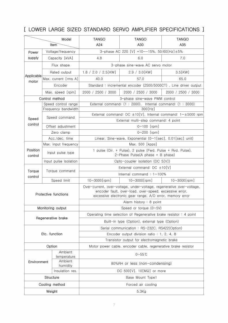
[ LOWER LARGE SIZED STANDARD SERVO AMPLIFIER SPECIFICATIONS ]
Model
Item
TANGO
A24
TANGO
A30
TANGO
A35
Power
supply
Voltage/frequency 3-phase AC 220 [V] +10~-15%, 50/60[Hz]±5%
Capacity [kVA] 4.8 6.0 7.0
Applicable
motor
Flux shape 3-phase sine-wave AC servo motor
Rated output 1.8 / 2.0 / 2.5[KW] 2.9 / 3.0[KW] 3.5[KW]
Max. current [rms A] 40.0 57.0 65.0
Encoder Standard : incremental encoder (2500/5000CT) , Line driver output
Max. speed [rpm] 2000 / 2500 / 3000 2000 / 2500 / 3000 2000 / 2500 / 3000
Control method 3-phase sine-wave PWM control
Speed
control
Speed control range External command: (1 : 2000), Internal command: (1 : 3000)
Frequency bandwidth 300[Hz]
Speed commandExternal command: DC ±10[V], Internal command: 1~±5000 rpm
External multi-step command: 4 point
Offset adjustment 0~100 [rpm]
Zero clamp 0~200 [rpm]
Acc./dec. time Linear, Sine-wave, Exponential (0~1[sec], 0.01[sec] unit)
Position
control
Max. input frequency Max. 500 [kpps]
Input pulse type1 pulse (Dir. + Pulse), 2 pulse (Fwd. Pulse + Rvd. Pulse),
2-Phase Pulse(A phase + B phase)
Input pulse isolation Opto-coupler isolation (DC 5[V])
Torque
control
Torque commandExternal command: DC ±10[V]
Internal command : 1~100%
Speed limit 10~3000[rpm] 10~3000[rpm] 10~3000[rpm]
Protective functions
Over-current, over-voltage, under-voltage, regenerative over-voltage,
encoder fault, over-load, over-speed, excessive error,
excessive electronic gear range, A/D error, memory error
Alarm history : 8 point
Monitoring output Speed or torque (0~5V)
Regenerative brakeOperating time selection of Regenerative brake resistor : 4 point
Built-in type (Option), external type (Option)
Etc. function
Serial communication : RS-232C, RS422(Option)
Encoder output division ratio : 1, 2, 4, 8
Transistor output for electromagnetic brake
Option Motor power cable, encoder cable, regenerative brake resistor
Environment
Ambient
temperature0~55℃
Ambient
humidity80%RH or less (non-condensing)
Insulation res. DC 500[V], 10[M ] or moreΩ
Structure Base Mount Type1
Cooling method Forced air cooling
Weight 5.3Kg
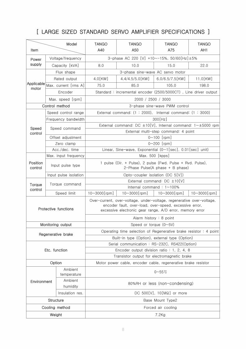
[ LARGE SIZED STANDARD SERVO AMPLIFIER SPECIFICATIONS ]
Model
Item
TANGO
A40
TANGO
A50
TANGO
A75
TANGO
AH1
Power
supply
Voltage/frequency 3-phase AC 220 [V] +10~-15%, 50/60[Hz]±5%
Capacity [kVA] 8.0 10.0 15.0 22.0
Applicable
motor
Flux shape 3-phase sine-wave AC servo motor
Rated output 4.0[KW] 4.4/4.5/5.0[KW] 6.0/6.5/7.5[KW] 11.0[KW]
Max. current [rms A] 75.0 85.0 105.0 198.0
Encoder Standard : incremental encoder (2500/5000CT) , Line driver output
Max. speed [rpm] 2000 / 2500 / 3000
Control method 3-phase sine-wave PWM control
Speed
control
Speed control range External command: (1 : 2000), Internal command: (1 : 3000)
Frequency bandwidth 300[Hz]
Speed commandExternal command: DC ±10[V], Internal command: 1~±5000 rpm
External multi-step command: 4 point
Offset adjustment 0~100 [rpm]
Zero clamp 0~200 [rpm]
Acc./dec. time Linear, Sine-wave, Exponential (0~1[sec], 0.01[sec] unit)
Position
control
Max. input frequency Max. 500 [kpps]
Input pulse type1 pulse (Dir. + Pulse), 2 pulse (Fwd. Pulse + Rvd. Pulse),
2-Phase Pulse(A phase + B phase)
Input pulse isolation Opto-coupler isolation (DC 5[V])
Torque
control
Torque commandExternal command: DC ±10[V]
Internal command : 1~100%
Speed limit 10~3000[rpm] 10~3000[rpm] 10~3000[rpm] 10~3000[rpm]
Protective functions
Over-current, over-voltage, under-voltage, regenerative over-voltage,
encoder fault, over-load, over-speed, excessive error,
excessive electronic gear range, A/D error, memory error
Alarm history : 8 point
Monitoring output Speed or torque (0~5V)
Regenerative brakeOperating time selection of Regenerative brake resistor : 4 point
Built-in type (Option), external type (Option)
Etc. function
Serial communication : RS-232C, RS422(Option)
Encoder output division ratio : 1, 2, 4, 8
Transistor output for electromagnetic brake
Option Motor power cable, encoder cable, regenerative brake resistor
Environment
Ambient
temperature0~55℃
Ambient
humidity80%RH or less (non-condensing)
Insulation res. DC 500[V], 10[M ] or moreΩ
Structure Base Mount Type2
Cooling method Forced air cooling
Weight 7.2Kg
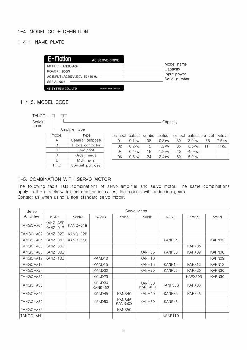
1-4. MODEL CODE DEFINITION
1-4-1. NAME PLATE
Model name
Capacity
Input power
Serial number
1-4-2. MODEL CODE
TANGO - □ □□
Series Capacityname
Amplifier type
1-5. COMBINATION WITH SERVO MOTOR
The following table lists combinations of servo amplifier and servo motor. The same combinations
apply to the models with electromagnetic brakes, the models with reduction gears.
Contact us when using a non-standard servo motor.
Servo
Amplifier
Servo Motor
KANZ KANQ KAND KANS KANH KANF KAFX KAFN
TANGO-A01KANZ-A5B
KANZ-01BKANQ-01B
TANGO-A02 KANZ-02B KANQ-02B
TANGO-A04 KANZ-04B KANQ-04B KANF04 KAFN03
TANGO-A06 KANZ-06B KAFX05
TANGO-A08 KANZ-08B KANH05 KANF08 KAFX09 KAFN06
TANGO-A12 KANZ-10B KAND10 KANH10 KAFN09
TANGO-A18 KAND15 KANH15 KANF15 KAFX13 KAFN12
TANGO-A24 KAND20 KANH20 KANF25 KAFX20 KAFN20
TANGO-A30 KAND25 KAFX30S KAFN30
TANGO-A35KAND30
KAND45SKANH30KANH40S KANF35S KAFX30
TANGO-A40 KAND45 KANS40 KANH40 KANF35 KAFX45
TANGO-A50 KAND50 KANS45KANS50S KANH50 KANF45
TANGO-A75 KANS50
TANGO-AH1 KANF110
symbol output symbol output symbol output symbol output
01 0.1kw 08 0.8kw 30 3.0kw 75 7.5kw
02 0.2kw 12 1.2kw 35 3.5kw H1 11kw
04 0.4kw 18 1.8kw 40 4.0kw
06 0.6kw 24 2.4kw 50 5.0kw
model type
A General-purpose
B 1 axis controller
C Low cost
D Order made
E Multi-axis
F~Z Special-purpose
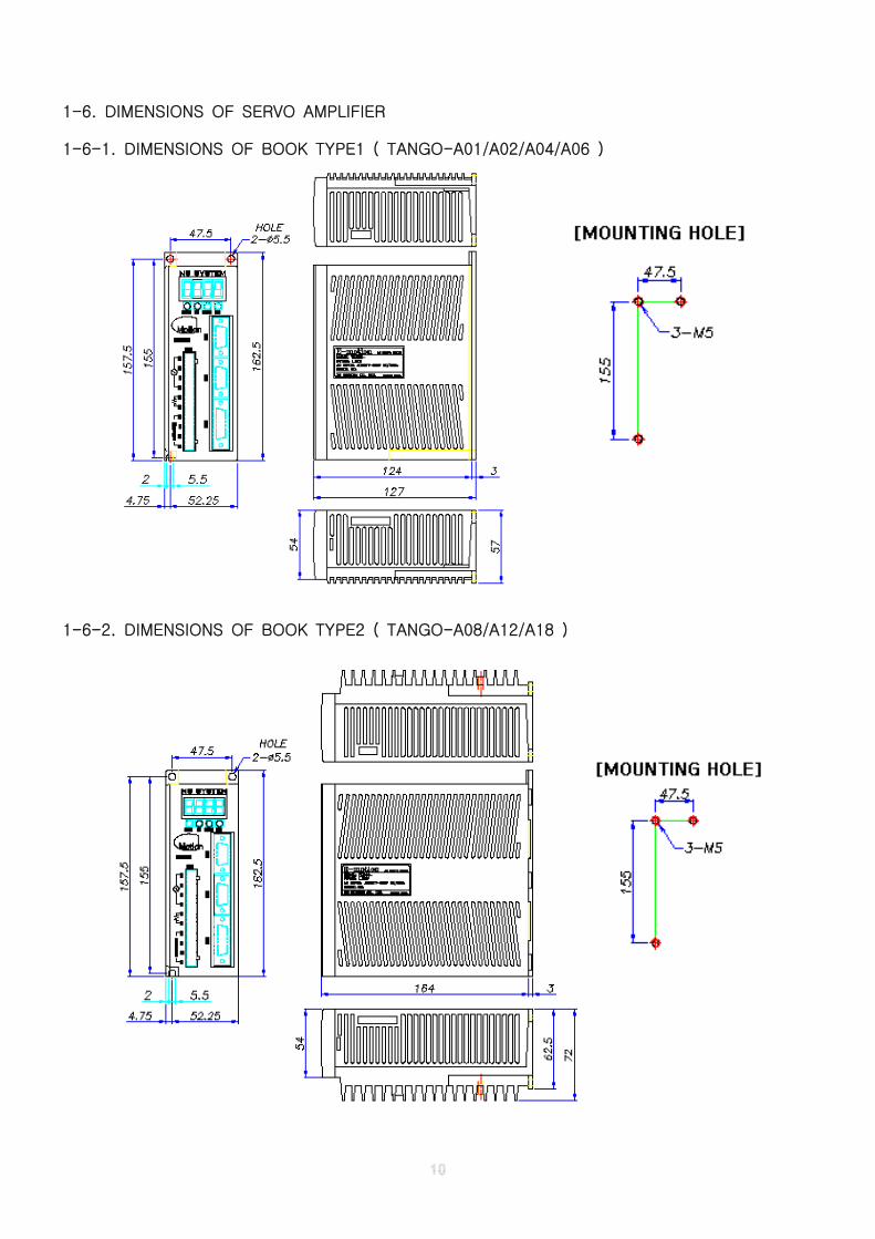
1-6. DIMENSIONS OF SERVO AMPLIFIER
1-6-1. DIMENSIONS OF BOOK TYPE1 ( TANGO-A01/A02/A04/A06 )
1-6-2. DIMENSIONS OF BOOK TYPE2 ( TANGO-A08/A12/A18 )
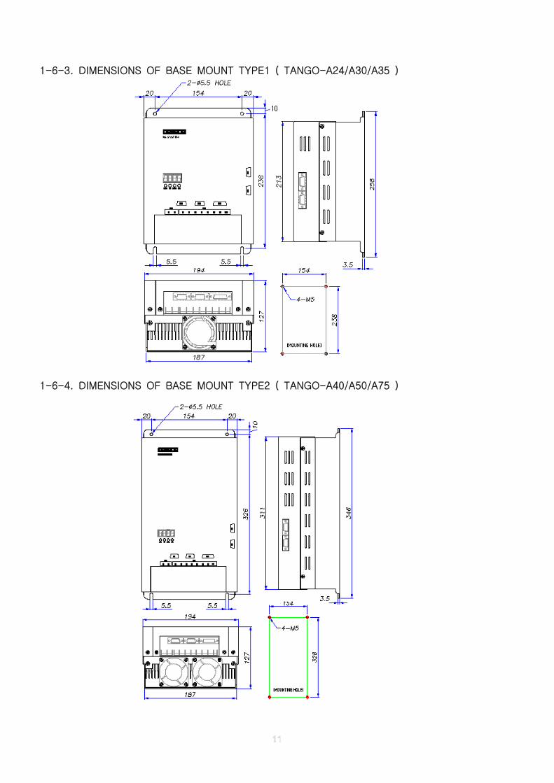
1-6-3. DIMENSIONS OF BASE MOUNT TYPE1 ( TANGO-A24/A30/A35 )
1-6-4. DIMENSIONS OF BASE MOUNT TYPE2 ( TANGO-A40/A50/A75 )
CHAPTER 2. INSTALLATION
2-1. CHECK ITEMS WHEN PRODUCT DELIVERED
Check the following items first when the product is delivered.
1. Check whether the product conforms to the ordered specifications.
2. Check whether the product is not damaged.
3. Check whether the coupling part is loosened.
4. Check whether the motor shaft is smooth and no stalled feeling when turned by hand.
5. Check whether the combinations of servo amplifier and servo motor is matched.
If any trouble, immediately contact the distributor you bought or us.☞
2-2. INSTALLATION DIRECTION AND CLEARANCES
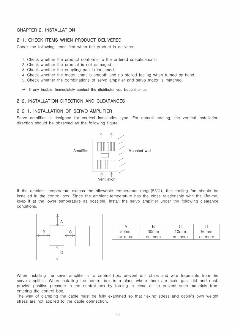
2-2-1. INSTALLATION OF SERVO AMPLIFIER
Servo amplifier is designed for vertical installation type. For natural cooling, the vertical installation
direction should be observed as the following figure.
Amplifier Mounted wall
Ventilation
If the ambient temperature excess the allowable temperature range(55 ), the cooling fan should be℃
installed in the control box. Since the ambient temperature has the close relationship with the lifetime,
keep it at the lower temperature as possible. Install the servo amplifier under the following clearance
conditions.
A
B C
D
When installing the servo amplifier in a control box, prevent drill chips and wire fragments from the
servo amplifier. When installing the control box in a place where there are toxic gas, dirt and dust,
provide positive pressure in the control box by forcing in clean air to prevent such materials from
entering the control box.
The way of clamping the cable must be fully examined so that flexing stress and cable's own weight
stress are not applied to the cable connection.
A B C D
50mm
or more
30mm
or more
10mm
or more
50mm
or more
2-2-2. INSTALLATION OF SERVO MOTOR
The servo motor is available for both vertical and horizontal installation. But since the bad environment
of the installation condition affects the lifetime of motor and the unexpected accident, it should be
installed according to the following descriptions.
☞ Since the rust-preventative is coated on the shaft and flange surface for rust-proof during the
preservation, be sure to clean the rust-preventative before installation.
☞ The servo motor is subject to be used in indoor environment. If there are much water and oil
drops around, the cover should be attached.
☞ When connecting with load, the shaft of motor should be aligned exactly with that of the counter
load. Otherwise, it cause the vibration, acoustic noise and damages.
The concentricity and gap should be less than 3/100mm.
☞ The excessive external shock may break the motor bearing and encoder.
If the reducer, pulley and coupling are used, do not apply the excessive shock(50G and above)
to the motor shaft.
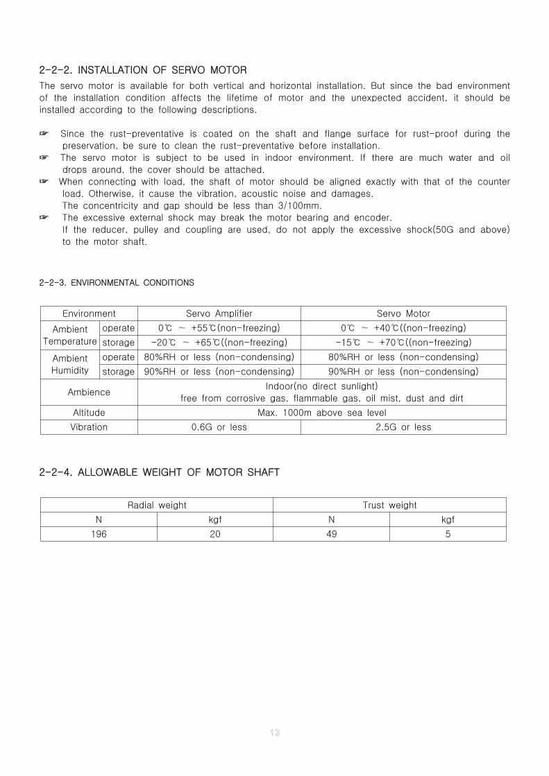
2-2-3. ENVIRONMENTAL CONDITIONS
Environment Servo Amplifier Servo Motor
Ambient
Temperature
operate 0 +55 (non-freezing)℃ ∼ ℃ 0 +40 ((non-freezing)℃ ∼ ℃
storage -20 +65 ((non-freezing)℃ ∼ ℃ -15 +70 ((non-freezing)℃ ∼ ℃
Ambient
Humidity
operate 80%RH or less (non-condensing) 80%RH or less (non-condensing)
storage 90%RH or less (non-condensing) 90%RH or less (non-condensing)
AmbienceIndoor(no direct sunlight)
free from corrosive gas, flammable gas, oil mist, dust and dirt
Altitude Max. 1000m above sea level
Vibration 0.6G or less 2.5G or less
2-2-4. ALLOWABLE WEIGHT OF MOTOR SHAFT
Radial weight Trust weight
N kgf N kgf
196 20 49 5
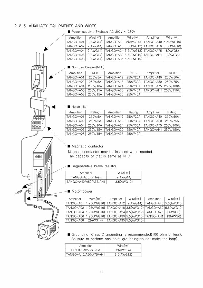
2-2-5. AUXILIARY EQUIPMENTS AND WIRES
Power supply : 3-phase AC 200V ~ 230V■
No-fuse breaker(NFB)■
Noise filter■
■ Magnetic contactor
Magnetic contactor may be installed when needed.
The capacity of that is same as NFB
■ Regenerative brake resistor
■ Motor power
■ Grounding: Class D grounding is recommended(100 ohm or less).
Be sure to perform one point grounding(do not make the loop).
Amplifier Wire[ ]㎟ Amplifier Wire[ ]㎟ Amplifier Wire[ ]㎟
TANGO-A01 2(AWG14) TANGO-A12 2(AWG14) TANGO-A40 5.5(AWG10)
TANGO-A02 2(AWG14) TANGO-A18 3.5(AWG12) TANGO-A50 5.5(AWG10)
TANGO-A04 2(AWG14) TANGO-A24 3.5(AWG12) TANGO-A75 8(AWG8)
TANGO-A06 2(AWG14) TANGO-A30 5.5(AWG10) TANGO-AH1 13(AWG6)
TANGO-A08 2(AWG14) TANGO-A35 5.5(AWG10)
Amplifier NFB Amplifier NFB Amplifier NFB
TANGO-A01 250V/5A TANGO-A12 250V/20A TANGO-A40 250V/50A
TANGO-A02 250V/5A TANGO-A18 250V/30A TANGO-A50 250V/75A
TANGO-A04 250V/10A TANGO-A24 250V/30A TANGO-A75 250V/100A
TANGO-A06 250V/15A TANGO-A30 250V/40A TANGO-AH1 250V/150A
TANGO-A08 250V/15A TANGO-A35 250V/40A
Amplifier Rating Amplifier Rating Amplifier Rating
TANGO-A01 250V/5A TANGO-A12 250V/20A TANGO-A40 250V/50A
TANGO-A02 250V/5A TANGO-A18 250V/30A TANGO-A50 250V/75A
TANGO-A04 250V/10A TANGO-A24 250V/30A TANGO-A75 250V/100A
TANGO-A06 250V/15A TANGO-A30 250V/40A TANGO-AH1 250V/150A
TANGO-A08 250V/15A TANGO-A35 250V/40A
Amplifier Wire[ ]㎟
TANGO-A35 or less 2(AWG14)
TANGO-A40/A50/A75/AH1 3.5(AWG12)
Amplifier Wire[ ]㎟ Amplifier Wire[ ]㎟ Amplifier Wire[ ]㎟
TANGO-A01 1.25(AWG16) TANGO-A12 2(AWG14) TANGO-A40 5.5(AWG10)
TANGO-A02 1.25(AWG16) TANGO-A18 3.5(AWG12) TANGO-A50 5.5(AWG10)
TANGO-A04 1.25(AWG16) TANGO-A24 3.5(AWG12) TANGO-A75 8(AWG8)
TANGO-A06 1.25(AWG16) TANGO-A30 5.5(AWG10) TANGO-AH1 13(AWG6)
TANGO-A08 2(AWG14) TANGO-A35 5.5(AWG10)
Amplifier Wire[ ]㎟
TANGO-A35 or less 2(AWG14)
TANGO-A40/A50/A75/AH1 3.5(AWG12)
CHAPTER 3. SIGNALS AND WIRING
3-1. PARTS IDENTIFICATION
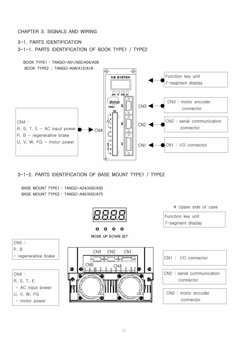
3-1-1. PARTS IDENTIFICATION OF BOOK TYPE1 / TYPE2
BOOK TYPE1 : TANGO-A01/A02/A04/A06
BOOK TYPE2 : TANGO-A08/A12/A18
3-1-2. PARTS IDENTIFICATION OF BASE MOUNT TYPE1 / TYPE2
BASE MOUNT TYPE1 : TANGO-A24/A30/A35
BASE MOUNT TYPE2 : TANGO-A40/A50/A75
# Upper side of case
CN2 : serial communication
connector
Function key unit
7-segment display
CN1 : I/O connector
CN3 : motor encoder
connector
CN4 :
R, S, T, E - AC input power
P, B - regenerative brake
U, V, W, FG - motor power
Function key unit
7-segment display
CN5 :
P, B
- regenerative brake CN1 : I/O connector
CN3 : motor encoder
connector
CN2 : serial communication
connector
CN4 :
R, S, T, E
- AC input power
U, V, W, FG
- motor power
3-2. CONNECTION DIAGRAM OF SERVO AMPLIFIER
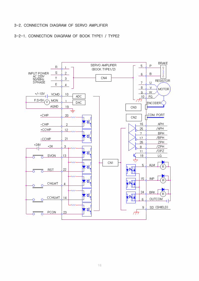
3-2-1. CONNECTION DIAGRAM OF BOOK TYPE1 / TYPE2
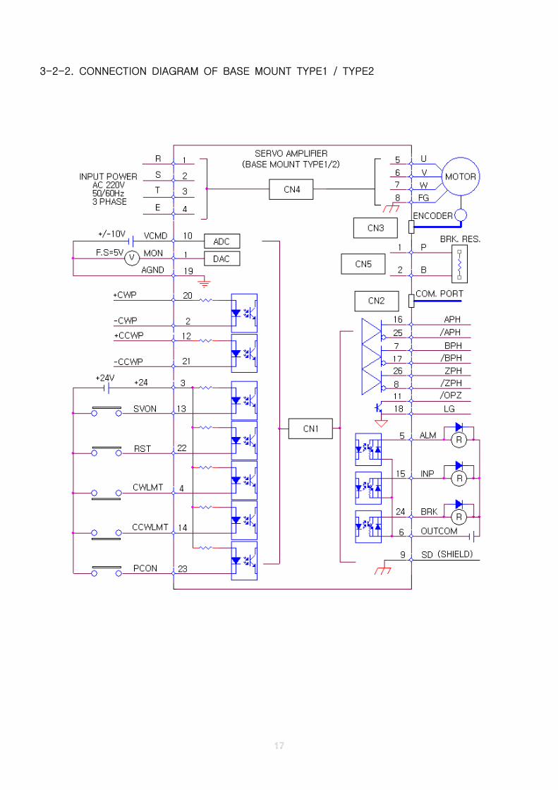
3-2-2. CONNECTION DIAGRAM OF BASE MOUNT TYPE1 / TYPE2
3-3. I/O SIGNALS OF CN1
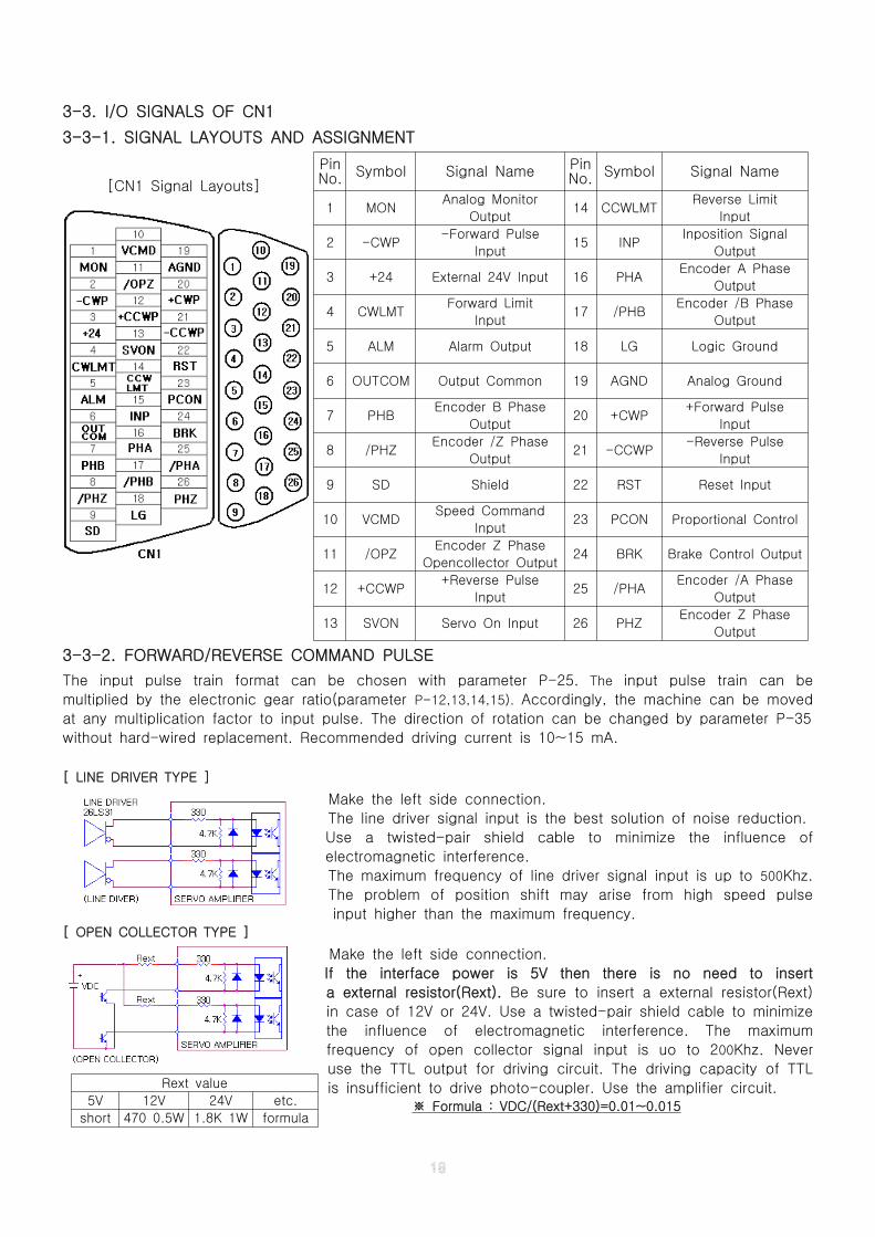
3-3-1. SIGNAL LAYOUTS AND ASSIGNMENT
[CN1 Signal Layouts]
3-3-2. FORWARD/REVERSE COMMAND PULSE
The input pulse train format can be chosen with parameter P-25. The input pulse train can be
multiplied by the electronic gear ratio(parameter P-12,13,14,15). Accordingly, the machine can be moved
at any multiplication factor to input pulse. The direction of rotation can be changed by parameter P-35
without hard-wired replacement. Recommended driving current is 10~15 mA.
[ LINE DRIVER TYPE ]
Make the left side connection.
The line driver signal input is the best solution of noise reduction.
Use a twisted-pair shield cable to minimize the influence of
electromagnetic interference.
The maximum frequency of line driver signal input is up to 500Khz.
The problem of position shift may arise from high speed pulse
input higher than the maximum frequency.[ OPEN COLLECTOR TYPE ]
Make the left side connection.
If the interface power is 5V then there is no need to insert
a external resistor(Rext). Be sure to insert a external resistor(Rext)
in case of 12V or 24V. Use a twisted-pair shield cable to minimize
the influence of electromagnetic interference. The maximum
frequency of open collector signal input is uo to 200Khz. Never
use the TTL output for driving circuit. The driving capacity of TTL
is insufficient to drive photo-coupler. Use the amplifier circuit.Formula : VDC/(Rext+330)=0.01~0.015※
PinNo. Symbol Signal Name Pin
No. Symbol Signal Name
1 MONAnalog Monitor
Output14 CCWLMT
Reverse Limit
Input
2 -CWP-Forward Pulse
Input15 INP
Inposition Signal
Output
3 +24 External 24V Input 16 PHAEncoder A Phase
Output
4 CWLMTForward Limit
Input17 /PHB
Encoder /B Phase
Output
5 ALM Alarm Output 18 LG Logic Ground
6 OUTCOM Output Common 19 AGND Analog Ground
7 PHBEncoder B Phase
Output20 +CWP
+Forward Pulse
Input
8 /PHZEncoder /Z Phase
Output21 -CCWP
-Reverse Pulse
Input
9 SD Shield 22 RST Reset Input
10 VCMDSpeed Command
Input23 PCON Proportional Control
11 /OPZEncoder Z Phase
Opencollector Output24 BRK Brake Control Output
12 +CCWP+Reverse Pulse
Input25 /PHA
Encoder /A Phase
Output
13 SVON Servo On Input 26 PHZEncoder Z Phase
Output
Rext value
5V 12V 24V etc.
short 470 0.5W 1.8K 1W formula
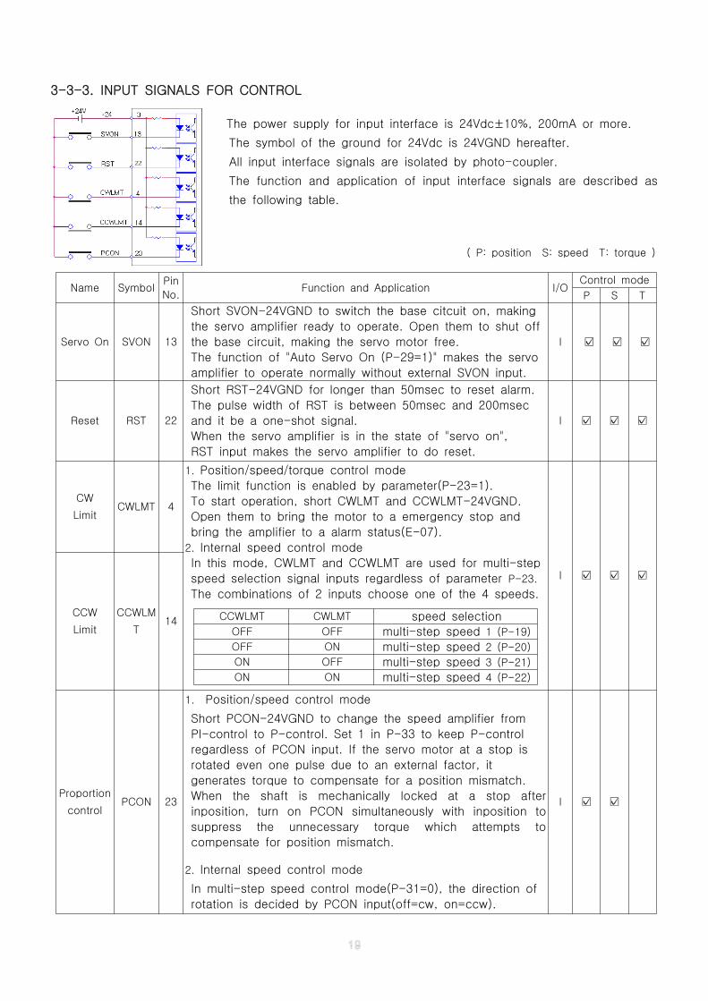
3-3-3. INPUT SIGNALS FOR CONTROL
The power supply for input interface is 24Vdc±10%, 200mA or more.
The symbol of the ground for 24Vdc is 24VGND hereafter.
All input interface signals are isolated by photo-coupler.
The function and application of input interface signals are described as
the following table.
( P: position S: speed T: torque )
Name SymbolPin
No.Function and Application I/O
Control mode
P S T
Servo On SVON 13
Short SVON-24VGND to switch the base citcuit on, making
the servo amplifier ready to operate. Open them to shut off
the base circuit, making the servo motor free.
The function of "Auto Servo On (P-29=1)" makes the servo
amplifier to operate normally without external SVON input.
I ☑ ☑ ☑
Reset RST 22
Short RST-24VGND for longer than 50msec to reset alarm.
The pulse width of RST is between 50msec and 200msec
and it be a one-shot signal.
When the servo amplifier is in the state of "servo on",
RST input makes the servo amplifier to do reset.
I ☑ ☑ ☑
CW
LimitCWLMT 4
1. Position/speed/torque control mode
The limit function is enabled by parameter(P-23=1).
To start operation, short CWLMT and CCWLMT-24VGND.
Open them to bring the motor to a emergency stop and
bring the amplifier to a alarm status(E-07).
2. Internal speed control mode
In this mode, CWLMT and CCWLMT are used for multi-step
speed selection signal inputs regardless of parameter P-23.
The combinations of 2 inputs choose one of the 4 speeds.
CCWLMT CWLMT speed selectionOFF OFF multi-step speed 1 (P-19)
OFF ON multi-step speed 2 (P-20)
ON OFF multi-step speed 3 (P-21)
ON ON multi-step speed 4 (P-22)
I ☑ ☑ ☑
CCW
Limit
CCWLM
T14
Proportion
controlPCON 23
1. Position/speed control mode
Short PCON-24VGND to change the speed amplifier from
PI-control to P-control. Set 1 in P-33 to keep P-control
regardless of PCON input. If the servo motor at a stop is
rotated even one pulse due to an external factor, it
generates torque to compensate for a position mismatch.
When the shaft is mechanically locked at a stop after
inposition, turn on PCON simultaneously with inposition to
suppress the unnecessary torque which attempts to
compensate for position mismatch.
2. Internal speed control mode
In multi-step speed control mode(P-31=0), the direction of
rotation is decided by PCON input(off=cw, on=ccw).
I ☑ ☑
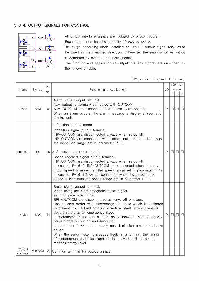
3-3-4. OUTPUT SIGNALS FOR CONTROL
All output interface signals are isolated by photo-coupler.
Each output port has the capacity of 100Vdc, 120mA.
The surge absorbing diode installed on the DC output signal relay must
be wired in the specified direction. Otherwise, the servo amplifier output
is damaged by over-current permanently.
The function and application of output interface signals are described as
the following table.
( P: position S: speed T: torque )
Name SymbolPin
No.Function and Application I/O
Control
mode
P S T
Alarm ALM 5
Alarm signal output terminal.
ALM output is normally contacted with OUTCOM.
ALM-OUTCOM are disconnected when an alarm occurs.
When an alarm occurs, the alarm message is display at segment
display unit.
O ☑ ☑ ☑
Inposition INP 15
1. Position control mode
Inposition signal output terminal.
INP-OUTCOM are disconnected always when servo off.
INP-OUTCOM are connected when droop pulse value is less than
the inposition range set in parameter P-17.
2. Speed/torque control mode
Speed reached signal output terminal.
INP-OUTCOM are disconnected always when servo off.
In case of P-16=0, INP-OUTCOM are connected when the servo
motor speed is more than the speed range set in parameter P-17
In case of P-16=1,They are connected when the servo motor
speed is less than the speed range set in parameter P-17.
O ☑ ☑ ☑
Brake BRK 24
Brake signal output terminal.
When using the electromagnetic brake signal,
set 1 in parameter P-42.
BRK-OUTCOM are disconnected at servo off or alarm.
Use a servo motor with electromagnetic brake which is designed
to prevent from a load drop on a vertical shaft or which ensure
double safety at an emergency stop.
In parameter P-43, set a time delay between electromagnetic
brake signal output on and servo on.
In parameter P-44, set a safety speed of electromagnetic brake
action.
When the servo motor is stopped freely at a running, the timing
of electromagnetic brake signal off is delayed until the speed
reaches safety level.
O ☑ ☑ ☑
Output
commonOUTCOM 6 Common terminal for output signals.
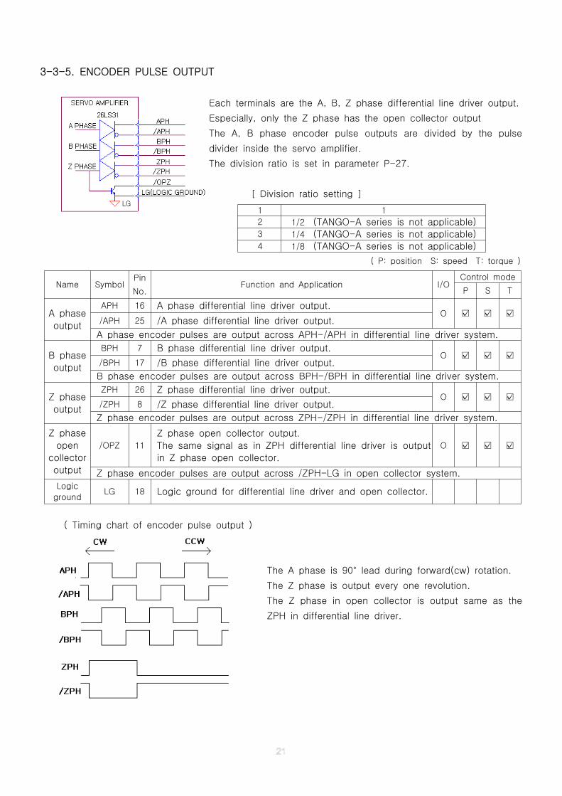
3-3-5. ENCODER PULSE OUTPUT
Each terminals are the A, B, Z phase differential line driver output.
Especially, only the Z phase has the open collector output
The A, B phase encoder pulse outputs are divided by the pulse
divider inside the servo amplifier.
The division ratio is set in parameter P-27.
[ Division ratio setting ]
( P: position S: speed T: torque )
( Timing chart of encoder pulse output )
The A phase is 90° lead during forward(cw) rotation.
The Z phase is output every one revolution.
The Z phase in open collector is output same as the
ZPH in differential line driver.
1 1
2 1/2 (TANGO-A series is not applicable)3 1/4 (TANGO-A series is not applicable)4 1/8 (TANGO-A series is not applicable)
Name SymbolPin
No.Function and Application I/O
Control mode
P S T
A phase
output
APH 16 A phase differential line driver output.O ☑ ☑ ☑
/APH 25 /A phase differential line driver output.
A phase encoder pulses are output across APH-/APH in differential line driver system.
B phase
output
BPH 7 B phase differential line driver output.O ☑ ☑ ☑
/BPH 17 /B phase differential line driver output.
B phase encoder pulses are output across BPH-/BPH in differential line driver system.
Z phase
output
ZPH 26 Z phase differential line driver output.O ☑ ☑ ☑
/ZPH 8 /Z phase differential line driver output.
Z phase encoder pulses are output across ZPH-/ZPH in differential line driver system.
Z phase
open
collector
output
/OPZ 11
Z phase open collector output.
The same signal as in ZPH differential line driver is output
in Z phase open collector.
O ☑ ☑ ☑
Z phase encoder pulses are output across /ZPH-LG in open collector system.
Logic
groundLG 18 Logic ground for differential line driver and open collector.
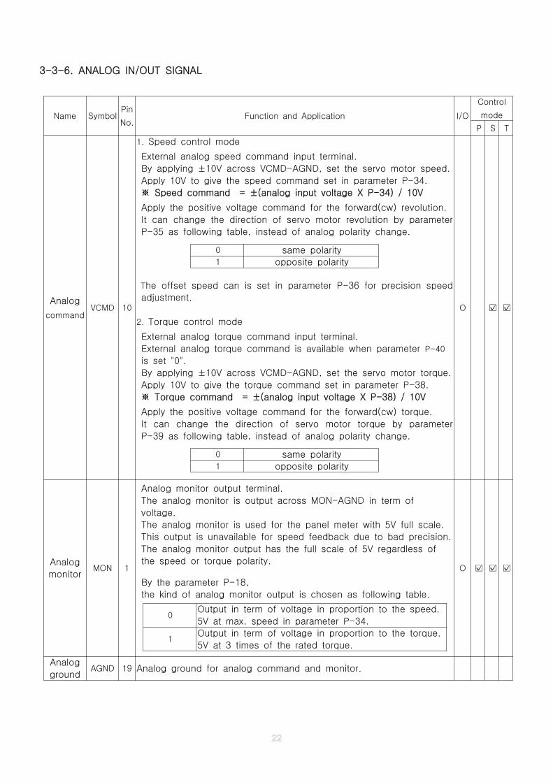
3-3-6. ANALOG IN/OUT SIGNAL
Name SymbolPin
No.Function and Application I/O
Control
mode
P S T
Analog
commandVCMD 10
1. Speed control mode
External analog speed command input terminal.
By applying ±10V across VCMD-AGND, set the servo motor speed.
Apply 10V to give the speed command set in parameter P-34.
Speed command = ±(analog input voltage X P-34) / 10V※
Apply the positive voltage command for the forward(cw) revolution.
It can change the direction of servo motor revolution by parameter
P-35 as following table, instead of analog polarity change.
The offset speed can is set in parameter P-36 for precision speed
adjustment.
2. Torque control mode
External analog torque command input terminal.
External analog torque command is available when parameter P-40
is set "0".
By applying ±10V across VCMD-AGND, set the servo motor torque.
Apply 10V to give the torque command set in parameter P-38.
Torque command = ±(analog input voltage X P-38) / 10V※
Apply the positive voltage command for the forward(cw) torque.
It can change the direction of servo motor torque by parameter
P-39 as following table, instead of analog polarity change.
0 same polarity1 opposite polarity
0 same polarity1 opposite polarity
O ☑ ☑
Analog
monitorMON 1
Analog monitor output terminal.
The analog monitor is output across MON-AGND in term of
voltage.
The analog monitor is used for the panel meter with 5V full scale.
This output is unavailable for speed feedback due to bad precision.
The analog monitor output has the full scale of 5V regardless of
the speed or torque polarity.
By the parameter P-18,
the kind of analog monitor output is chosen as following table.
0Output in term of voltage in proportion to the speed.
5V at max. speed in parameter P-34.
1Output in term of voltage in proportion to the torque.
5V at 3 times of the rated torque.
O ☑ ☑ ☑
Analog
groundAGND 19 Analog ground for analog command and monitor.
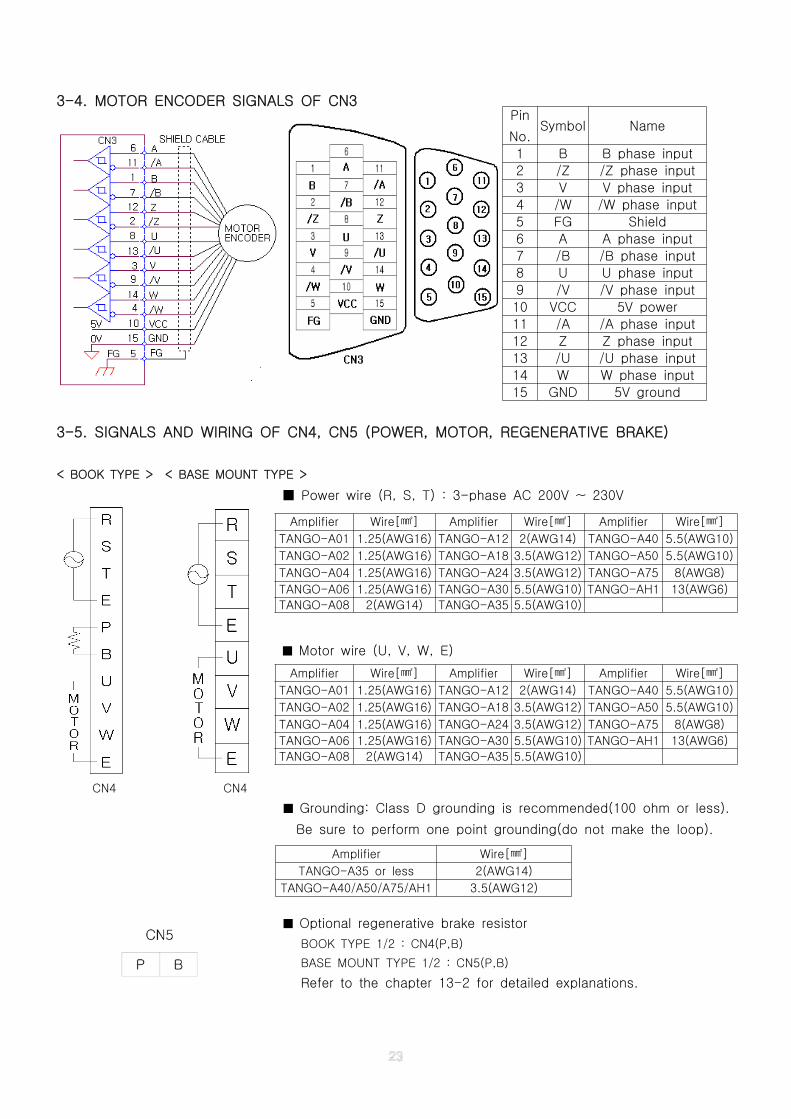
3-4. MOTOR ENCODER SIGNALS OF CN3
3-5. SIGNALS AND WIRING OF CN4, CN5 (POWER, MOTOR, REGENERATIVE BRAKE)
< BOOK TYPE > < BASE MOUNT TYPE >
Power wire (R, S, T) : 3-phase AC 200V ~ 230V■
■ Motor wire (U, V, W, E)
CN4 CN4
■ Grounding: Class D grounding is recommended(100 ohm or less).
Be sure to perform one point grounding(do not make the loop).
■ Optional regenerative brake resistor
BOOK TYPE 1/2 : CN4(P,B)
BASE MOUNT TYPE 1/2 : CN5(P,B)
Refer to the chapter 13-2 for detailed explanations.
Pin
No.Symbol Name
1 B B phase input
2 /Z /Z phase input
3 V V phase input
4 /W /W phase input
5 FG Shield
6 A A phase input
7 /B /B phase input
8 U U phase input
9 /V /V phase input
10 VCC 5V power
11 /A /A phase input
12 Z Z phase input
13 /U /U phase input
14 W W phase input
15 GND 5V ground
Amplifier Wire[ ]㎟ Amplifier Wire[ ]㎟ Amplifier Wire[ ]㎟
TANGO-A01 1.25(AWG16) TANGO-A12 2(AWG14) TANGO-A40 5.5(AWG10)
TANGO-A02 1.25(AWG16) TANGO-A18 3.5(AWG12) TANGO-A50 5.5(AWG10)
TANGO-A04 1.25(AWG16) TANGO-A24 3.5(AWG12) TANGO-A75 8(AWG8)
TANGO-A06 1.25(AWG16) TANGO-A30 5.5(AWG10) TANGO-AH1 13(AWG6)
TANGO-A08 2(AWG14) TANGO-A35 5.5(AWG10)
Amplifier Wire[ ]㎟
TANGO-A35 or less 2(AWG14)
TANGO-A40/A50/A75/AH1 3.5(AWG12)
CHAPTER 4. PARAMETER MODE
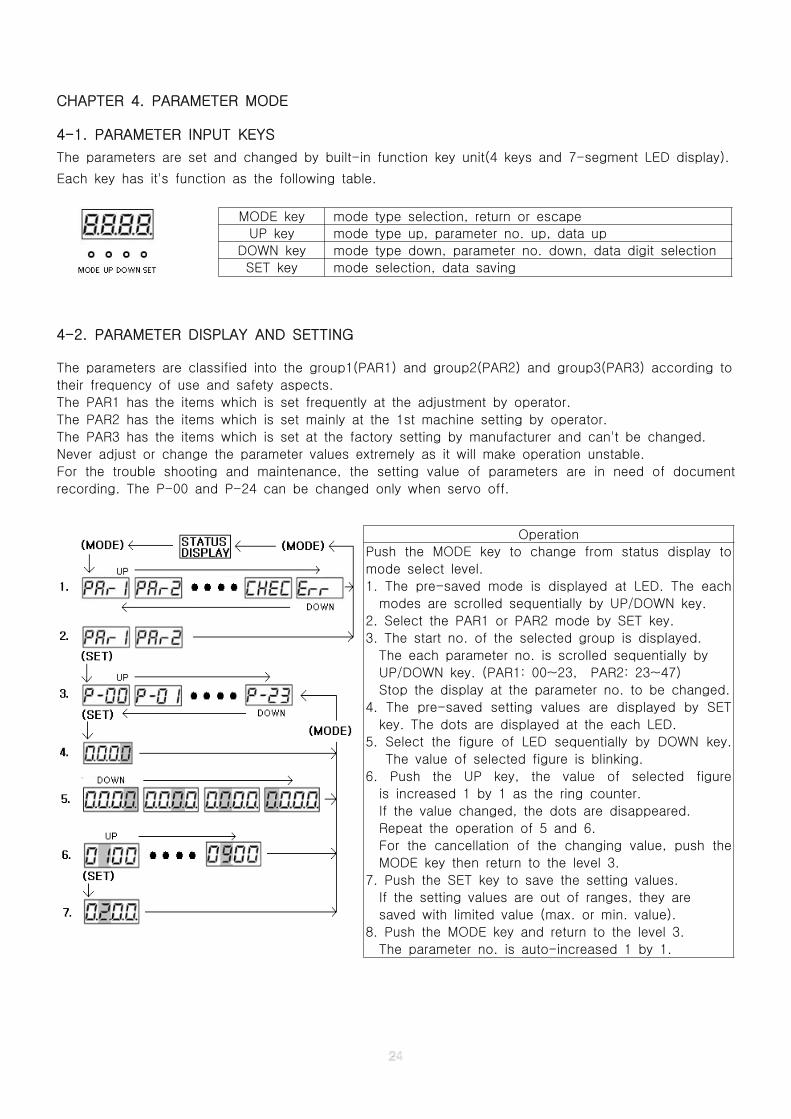
4-1. PARAMETER INPUT KEYS
The parameters are set and changed by built-in function key unit(4 keys and 7-segment LED display).
Each key has it's function as the following table.
4-2. PARAMETER DISPLAY AND SETTING
The parameters are classified into the group1(PAR1) and group2(PAR2) and group3(PAR3) according to
their frequency of use and safety aspects.
The PAR1 has the items which is set frequently at the adjustment by operator.
The PAR2 has the items which is set mainly at the 1st machine setting by operator.
The PAR3 has the items which is set at the factory setting by manufacturer and can't be changed.
Never adjust or change the parameter values extremely as it will make operation unstable.
For the trouble shooting and maintenance, the setting value of parameters are in need of document
recording. The P-00 and P-24 can be changed only when servo off.
MODE key mode type selection, return or escape
UP key mode type up, parameter no. up, data up
DOWN key mode type down, parameter no. down, data digit selection
SET key mode selection, data saving
Operation
Push the MODE key to change from status display to
mode select level.
1. The pre-saved mode is displayed at LED. The each
modes are scrolled sequentially by UP/DOWN key.
2. Select the PAR1 or PAR2 mode by SET key.
3. The start no. of the selected group is displayed.
The each parameter no. is scrolled sequentially by
UP/DOWN key. (PAR1: 00~23, PAR2: 23~47)
Stop the display at the parameter no. to be changed.
4. The pre-saved setting values are displayed by SET
key. The dots are displayed at the each LED.
5. Select the figure of LED sequentially by DOWN key.
The value of selected figure is blinking.
6. Push the UP key, the value of selected figure
is increased 1 by 1 as the ring counter.
If the value changed, the dots are disappeared.
Repeat the operation of 5 and 6.
For the cancellation of the changing value, push the
MODE key then return to the level 3.
7. Push the SET key to save the setting values.
If the setting values are out of ranges, they are
saved with limited value (max. or min. value).
8. Push the MODE key and return to the level 3.
The parameter no. is auto-increased 1 by 1.
4-3. DETAILS OF PARAMETERS
4-3-1. PARAMETER GROUP 1 (PAR1)
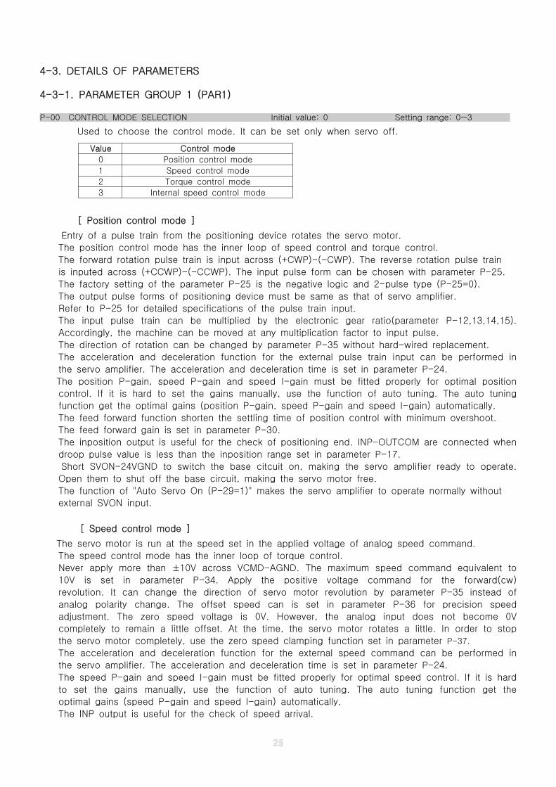
P-00 CONTROL MODE SELECTION Initial value: 0 Setting range: 0~3
Used to choose the control mode. It can be set only when servo off.
Value Control mode
0 Position control mode
1 Speed control mode
2 Torque control mode
3 Internal speed control mode
[ Position control mode ]
Entry of a pulse train from the positioning device rotates the servo motor.
The position control mode has the inner loop of speed control and torque control.
The forward rotation pulse train is input across (+CWP)-(-CWP). The reverse rotation pulse train
is inputed across (+CCWP)-(-CCWP). The input pulse form can be chosen with parameter P-25.
The factory setting of the parameter P-25 is the negative logic and 2-pulse type (P-25=0).
The output pulse forms of positioning device must be same as that of servo amplifier.
Refer to P-25 for detailed specifications of the pulse train input.
The input pulse train can be multiplied by the electronic gear ratio(parameter P-12,13,14,15).
Accordingly, the machine can be moved at any multiplication factor to input pulse.
The direction of rotation can be changed by parameter P-35 without hard-wired replacement.
The acceleration and deceleration function for the external pulse train input can be performed in
the servo amplifier. The acceleration and deceleration time is set in parameter P-24.
The position P-gain, speed P-gain and speed I-gain must be fitted properly for optimal position
control. If it is hard to set the gains manually, use the function of auto tuning. The auto tuning
function get the optimal gains (position P-gain, speed P-gain and speed I-gain) automatically.
The feed forward function shorten the settling time of position control with minimum overshoot.
The feed forward gain is set in parameter P-30.
The inposition output is useful for the check of positioning end. INP-OUTCOM are connected when
droop pulse value is less than the inposition range set in parameter P-17.
Short SVON-24VGND to switch the base citcuit on, making the servo amplifier ready to operate.
Open them to shut off the base circuit, making the servo motor free.
The function of "Auto Servo On (P-29=1)" makes the servo amplifier to operate normally without
external SVON input.
[ Speed control mode ]
The servo motor is run at the speed set in the applied voltage of analog speed command.
The speed control mode has the inner loop of torque control.
Never apply more than ±10V across VCMD-AGND. The maximum speed command equivalent to
10V is set in parameter P-34. Apply the positive voltage command for the forward(cw)
revolution. It can change the direction of servo motor revolution by parameter P-35 instead of
analog polarity change. The offset speed can is set in parameter P-36 for precision speed
adjustment. The zero speed voltage is 0V. However, the analog input does not become 0V
completely to remain a little offset. At the time, the servo motor rotates a little. In order to stop
the servo motor completely, use the zero speed clamping function set in parameter P-37.
The acceleration and deceleration function for the external speed command can be performed in
the servo amplifier. The acceleration and deceleration time is set in parameter P-24.
The speed P-gain and speed I-gain must be fitted properly for optimal speed control. If it is hard
to set the gains manually, use the function of auto tuning. The auto tuning function get the
optimal gains (speed P-gain and speed I-gain) automatically.
The INP output is useful for the check of speed arrival.
In case of P-16=0, INP-OUTCOM are connected when the servo motor speed is more than the
speed range set in parameter P-17.
In case of P-16=1,They are connected when the servo motor speed is less than the speed range
set in parameter P-17. Short SVON-24VGND to switch the base citcuit on, making the servo
amplifier ready to operate. Open them to shut off the base circuit, making the servo motor free.
The function of "Auto Servo On (P-29=1)" makes the servo amplifier to operate normally without
external SVON input.
[ Torque control mode ]
The servo motor is run at the torque set in the applied voltage of analog torque command.
The torque control mode has only it's own control loop. Therefore, the servo motor speed depend
on the load torque. Attention that the servo motor may run at over speed when the torque
command is too higher than the load torque. External analog torque command is available when
parameter P-40 is set "0". Never apply more than ±10V across VCMD-AGND. The maximum torque
command equivalent to 10V is set in parameter P-38. Apply the positive voltage command for the
forward(cw) torque. It can change the direction of servo motor torque by parameter P-39 instead
of analog polarity change. The acceleration and deceleration function for the external torque
command can be performed in the servo amplifier. The acceleration and deceleration time is set in
parameter P-24. The INP output is useful for the check of speed arrival. In case of P-16=0,
INP-OUTCOM are connected when the servo motor speed is more than the speed range set in
parameter P-17. In case of P-16=1,They are connected when the servo motor speed is less than
the speed range set in parameter P-17. Short SVON-24VGND to switch the base citcuit on,
making the servo amplifier ready to operate. Open them to shut off the base circuit, making the
servo motor free. The function of "Auto Servo On (P-29=1)" makes the servo amplifier to operate
normally without external SVON input.
[ Internal speed control mode ]
In this mode, there are 2 types of the speed control without external analog speed command.
The parameter P-31 select one of them. The one is a multi-step speed command control (P-31=0)
and the other is a internal speed command control (P-31=1).
1. Multi-step speed command control (P-31=0)
This mode is used for simple multi-step speed control with PLC or switch.
In this mode, CWLMT and CCWLMT are used for multi-step speed selection signal inputs
regardless of parameter P-23. The combinations of 2 inputs choose one of the 4 speeds.
CCWLMT CWLMT speed selection PCON SVONOFF OFF multi-step speed 1 (P-19)
OFF=CW ON=STARTOFF ON multi-step speed 2 (P-20)
ON OFF multi-step speed 3 (P-21)ON=CCW OFF=STOP
ON ON multi-step speed 4 (P-22)
The acceleration and deceleration time is set in parameter P-24. The INP output is used for
speed arrival function same as the speed control mode. The function of "Auto Servo On
(P-29=1)" makes the servo amplifier to operate normally without external SVON input.
The limit function is ignored regardless of parameter P-23.
2. Internal speed command control (P-31=1)
This mode is used for the simplest speed control with only one speed setting value.
The servo motor is run at the speed set in parameter P-32. The direction of revolution is set in
parameter P-35. The acceleration and deceleration time is set in parameter P-24.
The INP output is used for speed arrival function same as the speed control mode.
The function of "Auto Servo On (P-29=1)" makes the servo amplifier to operate normally without
external SVON input. The limit function is ignored regardless of parameter P-23.
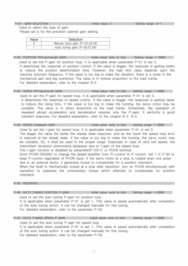
P-01 GAIN SELECTION Initial value: 0 Setting range: 0~1
Used to select the type of gain.
Please set 0 for the precision optimal gain setting.
Value Selection0 Manual input gain (P-02,03,04)
1 Auto tuning gain (P-06,07,08)
P-02 POSITION P(Proportional) GAIN Initial value: refer to lists Setting range: 1~9999
Used to set the P-gain for position loop. It is applicable when parameter P-01 is set 0.
It determines the response of position control. If the value is bigger, the response is getting better
to reduce the position determination time. However, the high limit value depends upon the
machine resonant frequency. If the value is too big to make the vibration, there is a noise in the
mechanical part and big overshoot. The value is in inverse proportion to the load inertia.
For detailed explanation, refer to the chapter 8-2.
P-03 SPEED P(Proportional) GAIN Initial value: refer to lists Setting range: 1~9999
Used to set the P-gain for speed loop. It is applicable when parameter P-01 is set 0.
It determines the response of speed control. If the value is bigger, the response is getting faster
to reduce the rising time. If the value is too big to make the hunting, the servo motor may be
unstable. The value is in direct proportion to the load inertia. Sometimes, the operation of
repeated abrupt acceleration and deceleration requires only the P-gain. It performs a good
transient response. For detailed explanation, refer to the chapter 8-2, 9-2.
P-04 SPEED I(Integral) GAIN Initial value: refer to lists Setting range: 1~9999
Used to set the I-gain for speed loop. It is applicable when parameter P-01 is set 0.
The bigger the value the better the steady state response, and as the result the speed loop error
is reduced at the steady state. If the value is too big to make the hunting, the servo motor may
be unstable. So, it shall be used in the proper range. Especially in case of ultra low speed, the
intermittent revolution phenomena disappear due to I-gain of the speed loop.
The I-gain function is disabled by parameter(P-23=1) or PCON terminal.
Short PCON-24VGND to change the speed amplifier from PI-control to P-control. Set 1 in P-33 to
keep P-control regardless of PCON input. If the servo motor at a stop is rotated even one pulse
due to an external factor, it generates torque to compensate for a position mismatch.
When the shaft is mechanically locked at a stop after inposition, turn on PCON simultaneously with
inposition to suppress the unnecessary torque which attempts to compensate for position
mismatch.
P-05 RESERVED
P-06 AUTO TUNING POSITION P GAIN Initial value: refer to lists Setting range: 1~9999
Used to set the auto tuning P-gain for position loop
It is applicable when parameter P-01 is set 1. This value is saved automatically after completion
of the auto tuning action. It can be changed manually for fine tuning.
For detailed explanation, refer to the parameter P-02.
P-07 AUTO TUNING SPEED P GAIN Initial value: refer to lists Setting range: 1~9999
Used to set the auto tuning P-gain for speed loop
It is applicable when parameter P-01 is set 1. This value is saved automatically after completion
of the auto tuning action. It can be changed manually for fine tuning.
For detailed explanation, refer to the parameter P-03.

P-08 AUTO TUNING SPEED I GAIN Initial value: refer to lists Setting range: 1~9999
Used to set the auto tuning I-gain for speed loop
It is applicable when parameter P-01 is set 1. This value is saved automatically after completion
of the auto tuning action. It can be changed manually for fine tuning.
For detailed explanation, refer to the parameter P-04.
P-09 AUTO TUNING SPEED Initial value: 500 Setting range: 200~2000
Used to set the speed of full-auto tuning action. The unit is rpm.
For the accurate estimation of load inertia, the auto tuning speed is at least more than 300 rpm.
For detailed explanation, refer to the chapter 16.
P-10 AUTO TUNING INERTIA RATIO Initial value: 100 Setting range: 100~9999
1. Semi-auto tuning mode : This value is the calculated load inertia percent value proportional to
the servo motor inertia. It is used for the reference of auto tuning gain estimation
2. Full-auto tuning mode : This value is saved automatically after completion of a full-auto tuning.
The result of a auto tuning action is the estimated load inertia percent value proportional to
the servo motor inertia.
P-11 OVER LOAD TIME Initial value: 10 Setting range: 1~30
Used to set the allowable time of over load. The unit is 0.1sec.
The over load check function is valid in position and speed control.
For a interval of setting value, if the required torque is higher than the torque limit value set in
parameter P-28 then the alarm E-02 has occurred.
When this alarm has occurred, check the machine and parameters carefully and restart.
If everything is good, it is recommended to replace by the higher capacity servo motor.
Notice that the servo amplifier may be damaged permanently due to the setting value more than
factory setting value.
P-12 ELECTRONIC GEAR DENOMINATOR1(1000'S) Initial value: 1 Setting rang: 1~9999
P-13 ELECTRONIC GEAR NUMERATOR1(1000'S) Initial value: 1 Setting rang: 1~9999
P-14 ELECTRONIC GEAR DENOMINATOR2(10000'S) Initial value: 0 Setting rang: 0~2
P-15 ELECTRONIC GEAR NUMERATOR2(10000'S) Initial value: 0 Setting rang: 0~2
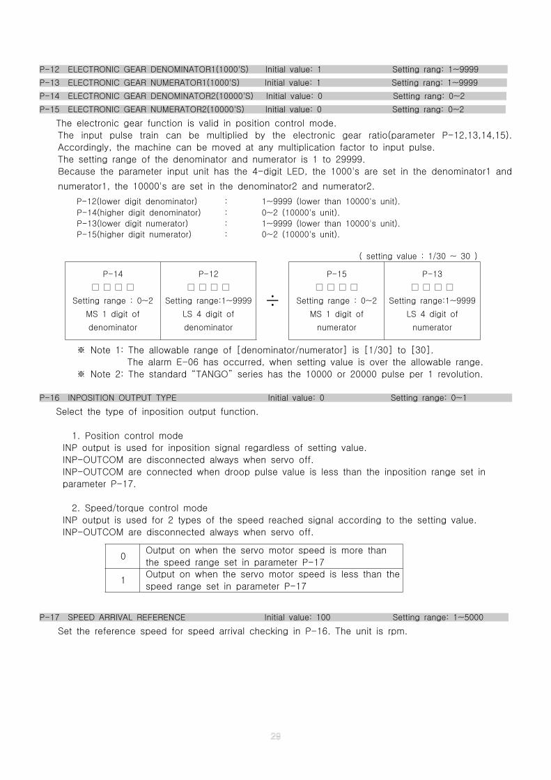
The electronic gear function is valid in position control mode.
The input pulse train can be multiplied by the electronic gear ratio(parameter P-12,13,14,15).
Accordingly, the machine can be moved at any multiplication factor to input pulse.
The setting range of the denominator and numerator is 1 to 29999.
Because the parameter input unit has the 4-digit LED, the 1000's are set in the denominator1 and
numerator1, the 10000's are set in the denominator2 and numerator2.
P-12(lower digit denominator) : 1~9999 (lower than 10000's unit).
P-14(higher digit denominator) : 0~2 (10000's unit).
P-13(lower digit numerator) : 1~9999 (lower than 10000's unit).
P-15(higher digit numerator) : 0~2 (10000's unit).
( setting value : 1/30 ~ 30 )
Note 1: The allowable range of [denominator/numerator] is [1/30] to [30].※
The alarm E-06 has occurred, when setting value is over the allowable range.
Note 2: The standard “TANGO” series has the 10000 or 20000 pulse per 1 revolution.※
P-16 INPOSITION OUTPUT TYPE Initial value: 0 Setting range: 0~1
Select the type of inposition output function.
1. Position control mode
INP output is used for inposition signal regardless of setting value.
INP-OUTCOM are disconnected always when servo off.
INP-OUTCOM are connected when droop pulse value is less than the inposition range set in
parameter P-17.
2. Speed/torque control mode
INP output is used for 2 types of the speed reached signal according to the setting value.
INP-OUTCOM are disconnected always when servo off.
P-17 SPEED ARRIVAL REFERENCE Initial value: 100 Setting range: 1~5000
Set the reference speed for speed arrival checking in P-16. The unit is rpm.
P-14
□ □ □ □
Setting range : 0~2
MS 1 digit of
denominator
P-12
□ □ □ □
Setting range:1~9999
LS 4 digit of
denominator
÷
P-15
□ □ □ □
Setting range : 0~2
MS 1 digit of
numerator
P-13
□ □ □ □
Setting range:1~9999
LS 4 digit of
numerator
0Output on when the servo motor speed is more than
the speed range set in parameter P-17
1Output on when the servo motor speed is less than the
speed range set in parameter P-17
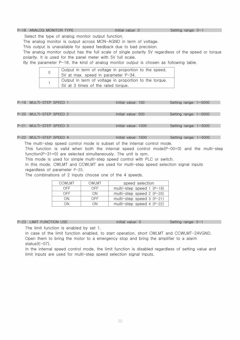
P-18 ANALOG MONITOR TYPE Initial value: 0 Setting range: 0~1
Select the type of analog monitor output function.
The analog monitor is output across MON-AGND in term of voltage.
This output is unavailable for speed feedback due to bad precision.
The analog monitor output has the full scale of single polarity 5V regardless of the speed or torque
polarity. It is used for the panel meter with 5V full scale.
By the parameter P-18, the kind of analog monitor output is chosen as following table.
P-19 MULTI-STEP SPEED 1 Initial value: 100 Setting range: 1~5000
P-20 MULTI-STEP SPEED 2 Initial value: 500 Setting range: 1~5000
P-21 MULTI-STEP SPEED 3 Initial value: 1000 Setting range: 1~5000
P-22 MULTI-STEP SPEED 4 Initial value: 1500 Setting range: 1~5000
The multi-step speed control mode is subset of the internal control mode.
This function is valid when both the internal speed control mode(P-00=3) and the multi-step
function(P-31=0) are selected simultaneously. The unit is rpm.
This mode is used for simple multi-step speed control with PLC or switch.
In this mode, CWLMT and CCWLMT are used for multi-step speed selection signal inputs
regardless of parameter P-23.
The combinations of 2 inputs choose one of the 4 speeds.
P-23 LIMIT FUNCTION USE Initial value: 0 Setting range: 0~1
The limit function is enabled by set 1.
In case of the limit function enabled, to start operation, short CWLMT and CCWLMT-24VGND.
Open them to bring the motor to a emergency stop and bring the amplifier to a alarm
status(E-07).
In the internal speed control mode, the limit function is disabled regardless of setting value and
limit inputs are used for multi-step speed selection signal inputs.
0Output in term of voltage in proportion to the speed.
5V at max. speed in parameter P-34.
1Output in term of voltage in proportion to the torque.
5V at 3 times of the rated torque.
CCWLMT CWLMT speed selectionOFF OFF multi-step speed 1 (P-19)
OFF ON multi-step speed 2 (P-20)
ON OFF multi-step speed 3 (P-21)
ON ON multi-step speed 4 (P-22)
4-3-2. PARAMETER GROUP 2 (PAR2)
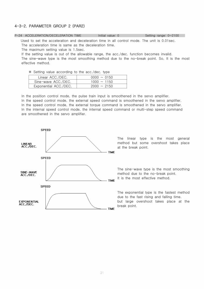
P-24 ACCELERATION/DECELERATION TIME Initial value: 0 Setting range: 0~2100
Used to set the acceleration and deceleration time in all control mode. The unit is 0.01sec.
The acceleration time is same as the deceleration time.
The maximum setting value is 1.5sec.
If the setting value is out of the allowable range, the acc./dec. function becomes invalid.
The sine-wave type is the most smoothing method due to the no-break point. So, It is the most
effective method.
Setting value according to the acc./dec. type※
Linear ACC./DEC. 0000 ~ 0150
Sine-wave ACC./DEC. 1000 ~ 1150
Exponential ACC./DEC. 2000 ~ 2150
In the position control mode, the pulse train input is smoothened in the servo amplifier.
In the speed control mode, the external speed command is smoothened in the servo amplifier.
In the speed control mode, the external torque command is smoothened in the servo amplifier.
In the internal speed control mode, the internal speed command or multi-step speed command
are smoothened in the servo amplifier.
The linear type is the most general
method but some overshoot takes place
at the break point.
The sine-wave type is the most smoothing
method due to the no-break point.
It is the most effective method.
The exponential type is the fastest method
due to the fast rising and falling time.
but large overshoot takes place at the
break point.
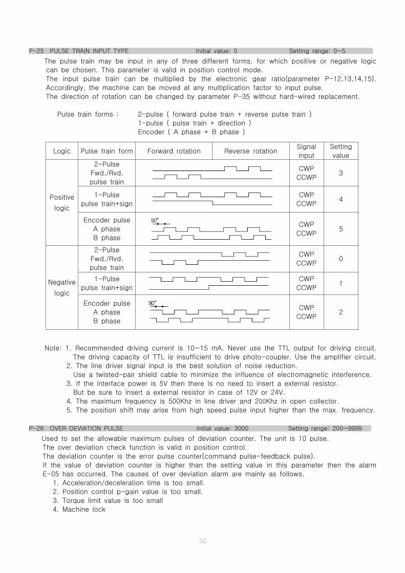
P-25 PULSE TRAIN INPUT TYPE Initial value: 0 Setting range: 0~5
The pulse train may be input in any of three different forms, for which positive or negative logic
can be chosen. This parameter is valid in position control mode.
The input pulse train can be multiplied by the electronic gear ratio(parameter P-12,13,14,15).
Accordingly, the machine can be moved at any multiplication factor to input pulse.
The direction of rotation can be changed by parameter P-35 without hard-wired replacement.
Pulse train forms : 2-pulse ( forward pulse train + reverse pulse train )
1-pulse ( pulse train + direction )
Encoder ( A phase + B phase )
Note: 1. Recommended driving current is 10~15 mA. Never use the TTL output for driving circuit.
The driving capacity of TTL is insufficient to drive photo-coupler. Use the amplifier circuit.
2. The line driver signal input is the best solution of noise reduction.
Use a twisted-pair shield cable to minimize the influence of electromagnetic interference.
3. If the interface power is 5V then there is no need to insert a external resistor.
But be sure to insert a external resistor in case of 12V or 24V.
4. The maximum frequency is 500Khz in line driver and 200Khz in open collector.
5. The position shift may arise from high speed pulse input higher than the max. frequency.
P-26 OVER DEVIATION PULSE Initial value: 3000 Setting range: 200~9999
Used to set the allowable maximum pulses of deviation counter. The unit is 10 pulse.
The over deviation check function is valid in position control.
The deviation counter is the error pulse counter(command pulse-feedback pulse).
If the value of deviation counter is higher than the setting value in this parameter then the alarm
E-05 has occurred. The causes of over deviation alarm are mainly as follows.
1. Acceleration/deceleration time is too small.
2. Position control p-gain value is too small.
3. Torque limit value is too small
4. Machine lock
Logic Pulse train form Forward rotation Reverse rotationSignal
input
Setting
value
Positive
logic
2-Pulse
Fwd./Rvd.
pulse train
CWP
CCWP3
1-Pulse
pulse train+sign
CWP
CCWP4
Encoder pulse
A phase
B phase
CWP
CCWP5
Negative
logic
2-Pulse
Fwd./Rvd.
pulse train
CWP
CCWP0
1-Pulse
pulse train+sign
CWP
CCWP1
Encoder pulse
A phase
B phase
CWP
CCWP2
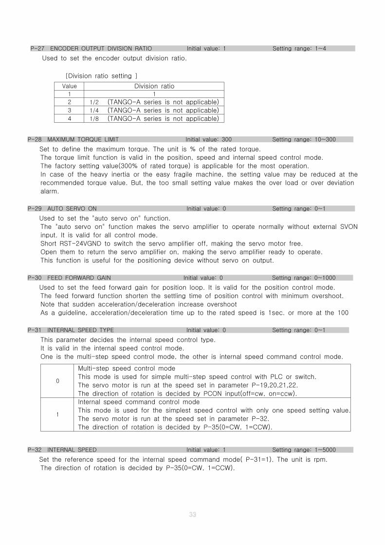
P-27 ENCODER OUTPUT DIVISION RATIO Initial value: 1 Setting range: 1~4
Used to set the encoder output division ratio.
[Division ratio setting ]
Value Division ratio1 1
2 1/2 (TANGO-A series is not applicable)3 1/4 (TANGO-A series is not applicable)4 1/8 (TANGO-A series is not applicable)
P-28 MAXIMUM TORQUE LIMIT Initial value: 300 Setting range: 10~300
Set to define the maximum torque. The unit is % of the rated torque.
The torque limit function is valid in the position, speed and internal speed control mode.
The factory setting value(300% of rated torque) is applicable for the most operation.
In case of the heavy inertia or the easy fragile machine, the setting value may be reduced at the
recommended torque value. But, the too small setting value makes the over load or over deviation
alarm.
P-29 AUTO SERVO ON Initial value: 0 Setting range: 0~1
Used to set the "auto servo on" function.
The "auto servo on" function makes the servo amplifier to operate normally without external SVON
input. It is valid for all control mode.
Short RST-24VGND to switch the servo amplifier off, making the servo motor free.
Open them to return the servo amplifier on, making the servo amplifier ready to operate.
This function is useful for the positioning device without servo on output.
P-30 FEED FORWARD GAIN Initial value: 0 Setting range: 0~1000
Used to set the feed forward gain for position loop. It is valid for the position control mode.
The feed forward function shorten the settling time of position control with minimum overshoot.
Note that sudden acceleration/deceleration increase overshoot
As a guideline, acceleration/deceleration time up to the rated speed is 1sec. or more at the 100
P-31 INTERNAL SPEED TYPE Initial value: 0 Setting range: 0~1
This parameter decides the internal speed control type.
It is valid in the internal speed control mode.
One is the multi-step speed control mode, the other is internal speed command control mode.
P-32 INTERNAL SPEED Initial value: 1 Setting range: 1~5000
Set the reference speed for the internal speed command mode( P-31=1). The unit is rpm.
The direction of rotation is decided by P-35(0=CW, 1=CCW).
0
Multi-step speed control mode
This mode is used for simple multi-step speed control with PLC or switch.
The servo motor is run at the speed set in parameter P-19,20,21,22.
The direction of rotation is decided by PCON input(off=cw, on=ccw).
1
Internal speed command control mode
This mode is used for the simplest speed control with only one speed setting value.
The servo motor is run at the speed set in parameter P-32.
The direction of rotation is decided by P-35(0=CW, 1=CCW).
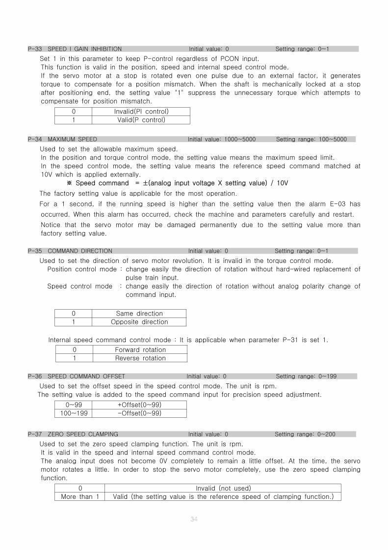
P-33 SPEED I GAIN INHIBITION Initial value: 0 Setting range: 0~1
Set 1 in this parameter to keep P-control regardless of PCON input.
This function is valid in the position, speed and internal speed control mode.
If the servo motor at a stop is rotated even one pulse due to an external factor, it generates
torque to compensate for a position mismatch. When the shaft is mechanically locked at a stop
after positioning end, the setting value "1" suppress the unnecessary torque which attempts to
compensate for position mismatch.
0 Invalid(PI control)
1 Valid(P control)
P-34 MAXIMUM SPEED Initial value: 1000~5000 Setting range: 100~5000
Used to set the allowable maximum speed.
In the position and torque control mode, the setting value means the maximum speed limit.
In the speed control mode, the setting value means the reference speed command matched at
10V which is applied externally.
Speed command = ±(analog input voltage X setting value) / 10V※
The factory setting value is applicable for the most operation.
For a 1 second, if the running speed is higher than the setting value then the alarm E-03 has
occurred. When this alarm has occurred, check the machine and parameters carefully and restart.
Notice that the servo motor may be damaged permanently due to the setting value more than
factory setting value.
P-35 COMMAND DIRECTION Initial value: 0 Setting range: 0~1
Used to set the direction of servo motor revolution. It is invalid in the torque control mode.
Position control mode : change easily the direction of rotation without hard-wired replacement of
pulse train input.
Speed control mode : change easily the direction of rotation without analog polarity change of
command input.
Internal speed command control mode : It is applicable when parameter P-31 is set 1.
P-36 SPEED COMMAND OFFSET Initial value: 0 Setting range: 0~199
Used to set the offset speed in the speed control mode. The unit is rpm.
The setting value is added to the speed command input for precision speed adjustment.
0~99 +Offset(0~99)
100~199 -Offset(0~99)
P-37 ZERO SPEED CLAMPING Initial value: 0 Setting range: 0~200
Used to set the zero speed clamping function. The unit is rpm.
It is valid in the speed and internal speed command control mode.
The analog input does not become 0V completely to remain a little offset. At the time, the servo
motor rotates a little. In order to stop the servo motor completely, use the zero speed clamping
function.
0 Invalid (not used)
More than 1 Valid (the setting value is the reference speed of clamping function.)
0 Same direction
1 Opposite direction
0 Forward rotation
1 Reverse rotation
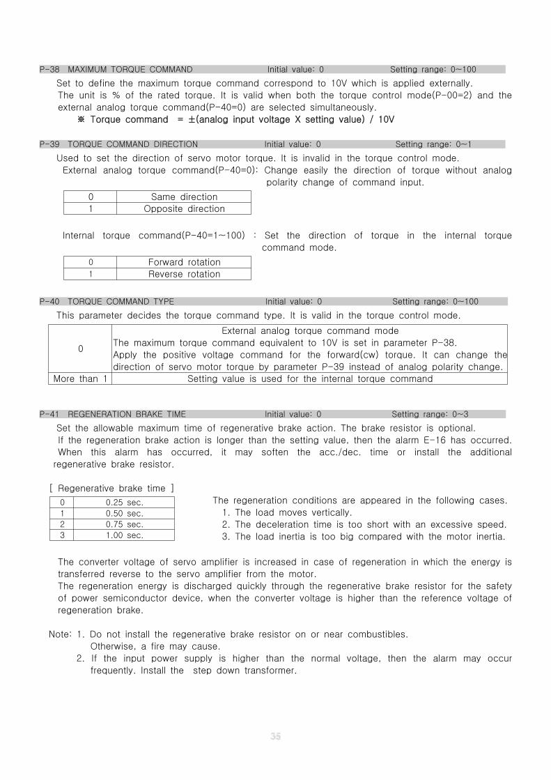
P-38 MAXIMUM TORQUE COMMAND Initial value: 0 Setting range: 0~100
Set to define the maximum torque command correspond to 10V which is applied externally.
The unit is % of the rated torque. It is valid when both the torque control mode(P-00=2) and the
external analog torque command(P-40=0) are selected simultaneously.
Torque command = ±(analog input voltage X setting value) / 10V※
P-39 TORQUE COMMAND DIRECTION Initial value: 0 Setting range: 0~1
Used to set the direction of servo motor torque. It is invalid in the torque control mode.
External analog torque command(P-40=0): Change easily the direction of torque without analog
polarity change of command input.
0 Same direction
1 Opposite direction
Internal torque command(P-40=1~100) : Set the direction of torque in the internal torque
command mode.
0 Forward rotation1 Reverse rotation
P-40 TORQUE COMMAND TYPE Initial value: 0 Setting range: 0~100
This parameter decides the torque command type. It is valid in the torque control mode.
P-41 REGENERATION BRAKE TIME Initial value: 0 Setting range: 0~3
Set the allowable maximum time of regenerative brake action. The brake resistor is optional.
If the regeneration brake action is longer than the setting value, then the alarm E-16 has occurred.
When this alarm has occurred, it may soften the acc./dec. time or install the additional
regenerative brake resistor.
[ Regenerative brake time ]
The regeneration conditions are appeared in the following cases.
1. The load moves vertically.
2. The deceleration time is too short with an excessive speed.
3. The load inertia is too big compared with the motor inertia.
The converter voltage of servo amplifier is increased in case of regeneration in which the energy is
transferred reverse to the servo amplifier from the motor.
The regeneration energy is discharged quickly through the regenerative brake resistor for the safety
of power semiconductor device, when the converter voltage is higher than the reference voltage of
regeneration brake.
Note: 1. Do not install the regenerative brake resistor on or near combustibles.
Otherwise, a fire may cause.
2. If the input power supply is higher than the normal voltage, then the alarm may occur
frequently. Install the step down transformer.
0
External analog torque command mode
The maximum torque command equivalent to 10V is set in parameter P-38.
Apply the positive voltage command for the forward(cw) torque. It can change the
direction of servo motor torque by parameter P-39 instead of analog polarity change.
More than 1 Setting value is used for the internal torque command
0 0.25 sec.
1 0.50 sec.
2 0.75 sec.
3 1.00 sec.
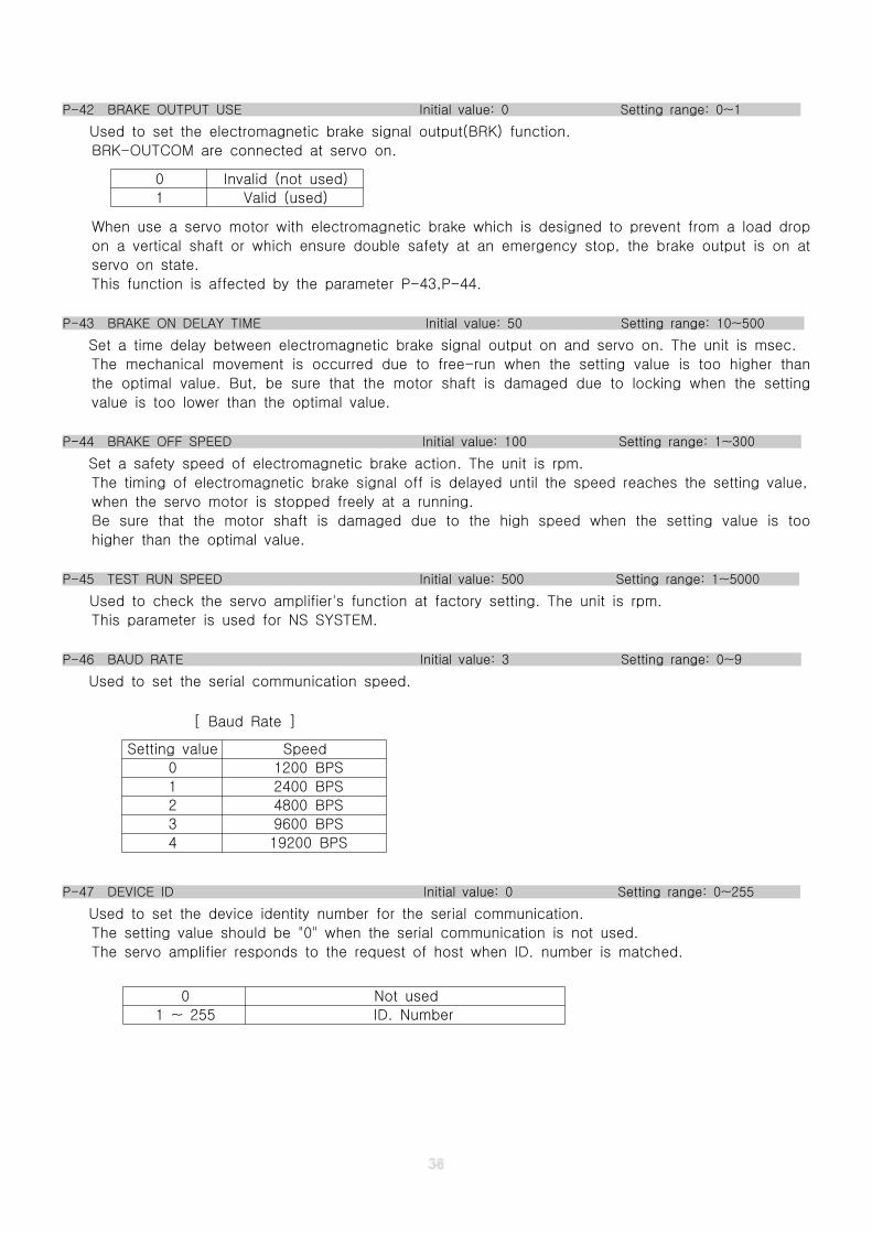
P-42 BRAKE OUTPUT USE Initial value: 0 Setting range: 0~1
Used to set the electromagnetic brake signal output(BRK) function.
BRK-OUTCOM are connected at servo on.
When use a servo motor with electromagnetic brake which is designed to prevent from a load drop
on a vertical shaft or which ensure double safety at an emergency stop, the brake output is on at
servo on state.
This function is affected by the parameter P-43,P-44.
P-43 BRAKE ON DELAY TIME Initial value: 50 Setting range: 10~500
Set a time delay between electromagnetic brake signal output on and servo on. The unit is msec.
The mechanical movement is occurred due to free-run when the setting value is too higher than
the optimal value. But, be sure that the motor shaft is damaged due to locking when the setting
value is too lower than the optimal value.
P-44 BRAKE OFF SPEED Initial value: 100 Setting range: 1~300
Set a safety speed of electromagnetic brake action. The unit is rpm.
The timing of electromagnetic brake signal off is delayed until the speed reaches the setting value,
when the servo motor is stopped freely at a running.
Be sure that the motor shaft is damaged due to the high speed when the setting value is too
higher than the optimal value.
P-45 TEST RUN SPEED Initial value: 500 Setting range: 1~5000
Used to check the servo amplifier's function at factory setting. The unit is rpm.
This parameter is used for NS SYSTEM.
P-46 BAUD RATE Initial value: 3 Setting range: 0~9
Used to set the serial communication speed.
[ Baud Rate ]
P-47 DEVICE ID Initial value: 0 Setting range: 0~255
Used to set the device identity number for the serial communication.
The setting value should be "0" when the serial communication is not used.
The servo amplifier responds to the request of host when ID. number is matched.
0 Not used
1 ~ 255 ID. Number
0 Invalid (not used)
1 Valid (used)
Setting value Speed
0 1200 BPS
1 2400 BPS
2 4800 BPS
3 9600 BPS
4 19200 BPS
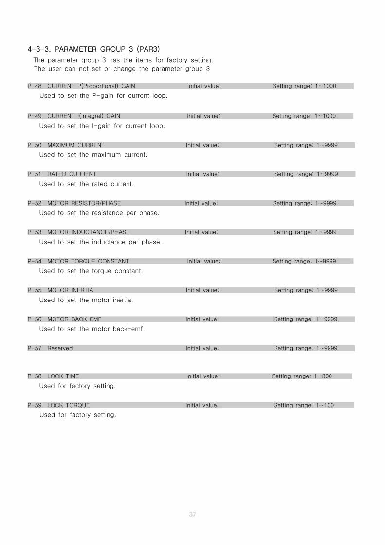
4-3-3. PARAMETER GROUP 3 (PAR3)
The parameter group 3 has the items for factory setting.
The user can not set or change the parameter group 3
P-48 CURRENT P(Proportional) GAIN Initial value: Setting range: 1~1000
Used to set the P-gain for current loop.
P-49 CURRENT I(Integral) GAIN Initial value: Setting range: 1~1000
Used to set the I-gain for current loop.
P-50 MAXIMUM CURRENT Initial value: Setting range: 1~9999
Used to set the maximum current.
P-51 RATED CURRENT Initial value: Setting range: 1~9999
Used to set the rated current.
P-52 MOTOR RESISTOR/PHASE Initial value: Setting range: 1~9999
Used to set the resistance per phase.
P-53 MOTOR INDUCTANCE/PHASE Initial value: Setting range: 1~9999
Used to set the inductance per phase.
P-54 MOTOR TORQUE CONSTANT Initial value: Setting range: 1~9999
Used to set the torque constant.
P-55 MOTOR INERTIA Initial value: Setting range: 1~9999
Used to set the motor inertia.
P-56 MOTOR BACK EMF Initial value: Setting range: 1~9999
Used to set the motor back-emf.
P-57 Reserved Initial value: Setting range: 1~9999
P-58 LOCK TIME Initial value: Setting range: 1~300
Used for factory setting.
P-59 LOCK TORQUE Initial value: Setting range: 1~100
Used for factory setting.
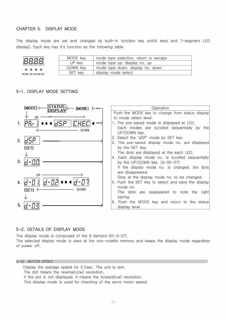
CHAPTER 5. DISPLAY MODE
The display mode are set and changed by built-in function key unit(4 keys and 7-segment LED
display). Each key has it's function as the following table.
5-1. DISPLAY MODE SETTING
5-2. DETAILS OF DISPLAY MODE
The display mode is composed of the 8 items(d-00~d-07).
The selected display mode is save at the non-volatile memory and keeps the display mode regardless
of power off.
d-00 MOTOR SPEED
Display the average speed for 0.2sec. The unit is rpm.
The dot means the reverse(ccw) revolution.
If the dot is not displayed, it means the forward(cw) revolution.
This display mode is used for checking of the servo motor speed.
MODE key mode type selection, return or escape
UP key mode type up, display no. up
DOWN key mode type down, display no. down
SET key display mode select
Operation
Push the MODE key to change from status display
to mode select level.
1. The pre-saved mode is displayed at LED.
Each modes are scrolled sequentially by the
UP/DOWN key.
2. Select the "dSP" mode by SET key.
3. The pre-saved display mode no. are displayed
by the SET key.
The dots are displayed at the each LED.
4. Each display mode no. is scrolled sequentially
by the UP/DOWN key. (d-00~07)
If the display mode no. is changed, the dots
are disappeared.
Stop at the display mode no. to be changed.
5. Push the SET key to select and save the display
mode no.
The dots are reappeared to note the right
saving.
6. Push the MODE key and return to the status
display level
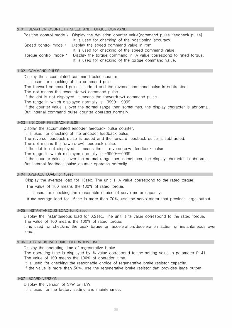
d-01 DEVIATION COUNTER / SPEED AND TORQUE COMMAND
Position control mode : Display the deviation counter value(command pulse-feedback pulse).
It is used for checking of the positioning accuracy.
Speed control mode : Display the speed command value in rpm.
It is used for checking of the speed command value.
Torque control mode : Display the torque command in % value correspond to rated torque.
It is used for checking of the torque command value.
d-02 COMMAND PULSE
Display the accumulated command pulse counter.
It is used for checking of the command pulse.
The forward command pulse is added and the reverse command pulse is subtracted.
The dot means the reverse(ccw) command pulse.
If the dot is not displayed, it means the forward(cw) command pulse.
The range in which displayed normally is -9999~+9999.
If the counter value is over the normal range then sometimes, the display character is abnormal.
But internal command pulse counter operates normally.
d-03 ENCODER FEEDBACK PULSE
Display the accumulated encoder feedback pulse counter.
It is used for checking of the encoder feedback pulse.
The reverse feedback pulse is added and the forward feedback pulse is subtracted.
The dot means the forward(cw) feedback pulse.
If the dot is not displayed, it means the reverse(ccw) feedback pulse.
The range in which displayed normally is -9999~+9999.
If the counter value is over the normal range then sometimes, the display character is abnormal.
But internal feedback pulse counter operates normally.
d-04 AVERAGE LOAD for 15sec.
Display the average load for 15sec. The unit is % value correspond to the rated torque.
The value of 100 means the 100% of rated torque.
It is used for checking the reasonable choice of servo motor capacity.
If the average load for 15sec is more than 70%, use the servo motor that provides large output.
d-05 INSTANTANEOUS LOAD for 0.2sec.
Display the instantaneous load for 0.2sec. The unit is % value correspond to the rated torque.
The value of 100 means the 100% of rated torque.
It is used for checking the peak torque on acceleration/deceleration action or instantaneous over
load.
d-06 REGENERATIVE BRAKE OPERATION TIME
Display the operating time of regenerative brake.
The operating time is displayed by % value correspond to the setting value in parameter P-41.
The value of 100 means the 100% of operation time.
It is used for checking the reasonable choice of regenerative brake resistor capacity.
If the value is more than 50%, use the regenerative brake resistor that provides large output.
d-07 BOARD VERSION
Display the version of S/W or H/W.
It is used for the factory setting and maintenance.
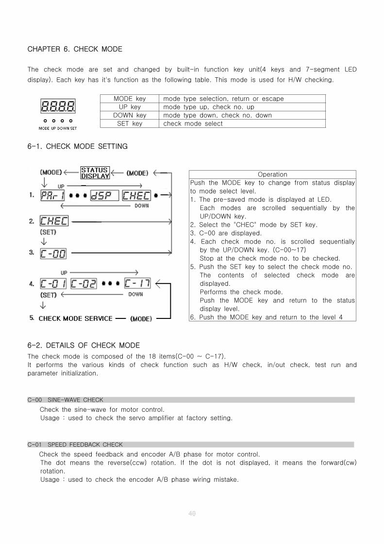
CHAPTER 6. CHECK MODE
The check mode are set and changed by built-in function key unit(4 keys and 7-segment LED
display). Each key has it's function as the following table. This mode is used for H/W checking.
6-1. CHECK MODE SETTING
6-2. DETAILS OF CHECK MODE
The check mode is composed of the 18 items(C-00 ~ C-17).
It performs the various kinds of check function such as H/W check, in/out check, test run and
parameter initialization.
C-00 SINE-WAVE CHECK
Check the sine-wave for motor control.
Usage : used to check the servo amplifier at factory setting.
C-01 SPEED FEEDBACK CHECK
Check the speed feedback and encoder A/B phase for motor control.
The dot means the reverse(ccw) rotation. If the dot is not displayed, it means the forward(cw)
rotation.
Usage : used to check the encoder A/B phase wiring mistake.
MODE key mode type selection, return or escape
UP key mode type up, check no. up
DOWN key mode type down, check no. down
SET key check mode select
Operation
Push the MODE key to change from status display
to mode select level.
1. The pre-saved mode is displayed at LED.
Each modes are scrolled sequentially by the
UP/DOWN key.
2. Select the "CHEC" mode by SET key.
3. C-00 are displayed.
4. Each check mode no. is scrolled sequentially
by the UP/DOWN key. (C-00~17)
Stop at the check mode no. to be checked.
5. Push the SET key to select the check mode no.
The contents of selected check mode are
displayed.
Performs the check mode.
Push the MODE key and return to the status
display level.
6. Push the MODE key and return to the level 4
C-02 ENCODER UVW SIGNAL CHECK
Check the encoder U/V/W phase for motor control.
When the servo motor shaft is rotated slowly toward clock-wise direction by hand, U/V/W phase
signal is displayed sequentially as follows
100 --> 101 --> 001 --> 011 --> 010 --> 110 --> 100 --> repeat
Usage : used to check the encoder U/V/W phase wiring mistake.
C-03 ANALOG INPUT CHECK
Check the analog input port. The dot means the negative voltage.
Usage : used to check the analog command input.
C-04 INVERTER H/W CHECK
Check the inverter(dc-link) H/W.
Display the peak value of AC voltage input. The peak value is times as nominal voltage.
Usage : used to check the AC voltage input and inverter H/W.
C-05 U PHASE CURRENT SENSOR OFFSET
Check the offset value of U phase current sensor.
It is a substandard device which is more than 60(300mV).
Usage : used to check the current sensor and relative H/W.
C-06 V PHASE CURRENT SENSOR OFFSET
Check the offset value of V phase current sensor.
It is a substandard device which is more than 60(300mV).
Usage : used to check the current sensor and relative H/W.
C-07 U PHASE CURRENT SENSOR
Check the characteristic of U phase current sensor.
Usage : used to check the servo amplifier at factory setting.
C-08 V PHASE CURRENT SENSOR
Check the characteristic of V phase current sensor.
Usage : used to check the servo amplifier at factory setting.
C-09 DEVIATION COUNTER CHECK
Check the deviation counter.
Usage : used to check the servo amplifier at factory setting.
+10V +2048
0V 0
-10V -2048
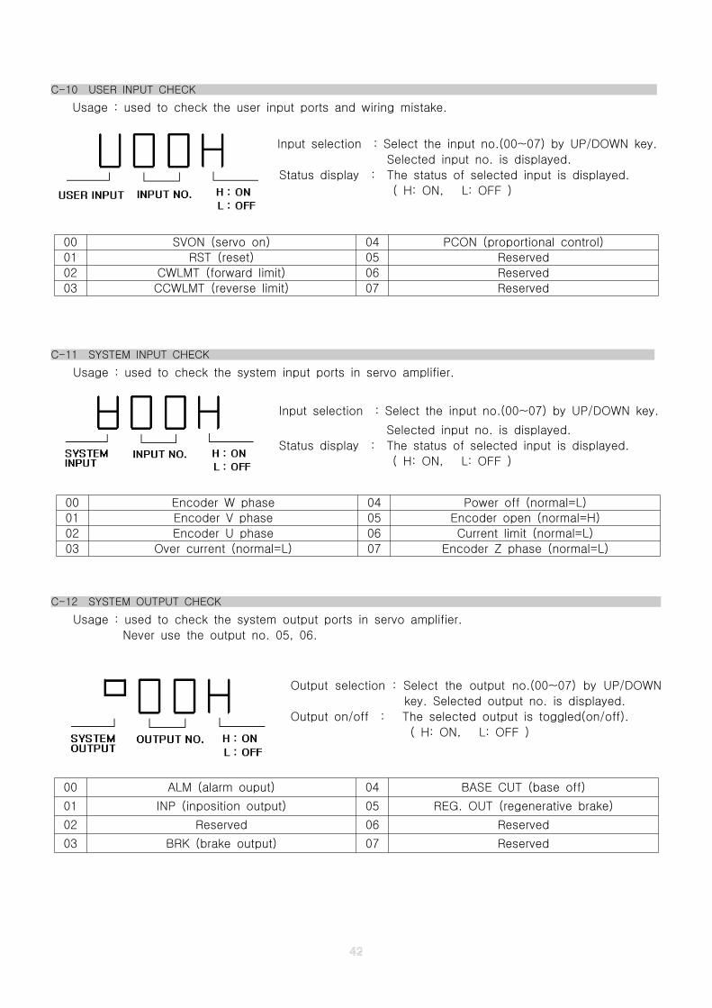
C-10 USER INPUT CHECK
Usage : used to check the user input ports and wiring mistake.
Input selection : Select the input no.(00~07) by UP/DOWN key.
Selected input no. is displayed.
Status display : The status of selected input is displayed.
( H: ON, L: OFF )
C-11 SYSTEM INPUT CHECK
Usage : used to check the system input ports in servo amplifier.
Input selection : Select the input no.(00~07) by UP/DOWN key.
Selected input no. is displayed.
Status display : The status of selected input is displayed.
( H: ON, L: OFF )
C-12 SYSTEM OUTPUT CHECK
Usage : used to check the system output ports in servo amplifier.
Never use the output no. 05, 06.
Output selection : Select the output no.(00~07) by UP/DOWN
key. Selected output no. is displayed.
Output on/off : The selected output is toggled(on/off).
( H: ON, L: OFF )
00 SVON (servo on) 04 PCON (proportional control)
01 RST (reset) 05 Reserved
02 CWLMT (forward limit) 06 Reserved
03 CCWLMT (reverse limit) 07 Reserved
00 Encoder W phase 04 Power off (normal=L)
01 Encoder V phase 05 Encoder open (normal=H)
02 Encoder U phase 06 Current limit (normal=L)
03 Over current (normal=L) 07 Encoder Z phase (normal=L)
00 ALM (alarm ouput) 04 BASE CUT (base off)
01 INP (inposition output) 05 REG. OUT (regenerative brake)
02 Reserved 06 Reserved
03 BRK (brake output) 07 Reserved
C-13 TEST RUN
Used to check the jog running at factory setting.
The test run speed value is set in parameter P-45.
The forward(cw) rotation running is started by UP key and reverse(ccw) rotation running is started
by DOWN key. The servo motor is stopped by the SET key.
Usage : used to check the servo amplifier at factory setting and 1st installation.
C-14 PARAMETER INITIALIZATION
Used to initialize the parameter with factory setting value.
On the 'cccc' status, the parameter initialization is started.
The '----' status is displayed at the end of initialization.
Push the MODE key to return to the main check mode
Usage : used to check the servo amplifier at factory setting.
C-15 RESERVED
C-16 RESERVED
C-17 RESERVED
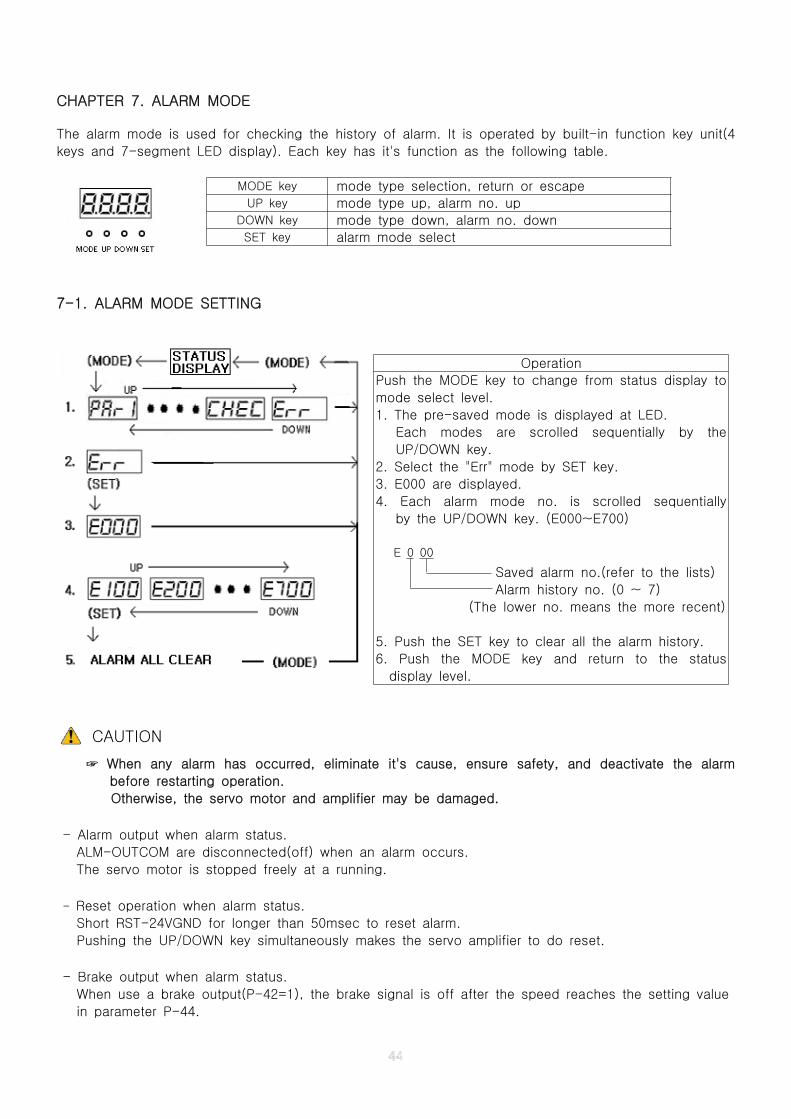
CHAPTER 7. ALARM MODE
The alarm mode is used for checking the history of alarm. It is operated by built-in function key unit(4
keys and 7-segment LED display). Each key has it's function as the following table.
7-1. ALARM MODE SETTING
CAUTION
☞ When any alarm has occurred, eliminate it's cause, ensure safety, and deactivate the alarm
before restarting operation.
Otherwise, the servo motor and amplifier may be damaged.
- Alarm output when alarm status.
ALM-OUTCOM are disconnected(off) when an alarm occurs.
The servo motor is stopped freely at a running.
- Reset operation when alarm status.
Short RST-24VGND for longer than 50msec to reset alarm.
Pushing the UP/DOWN key simultaneously makes the servo amplifier to do reset.
- Brake output when alarm status.
When use a brake output(P-42=1), the brake signal is off after the speed reaches the setting value
in parameter P-44.
MODE key mode type selection, return or escapeUP key mode type up, alarm no. up
DOWN key mode type down, alarm no. downSET key alarm mode select
Operation
Push the MODE key to change from status display to
mode select level.
1. The pre-saved mode is displayed at LED.
Each modes are scrolled sequentially by the
UP/DOWN key.
2. Select the "Err" mode by SET key.
3. E000 are displayed.
4. Each alarm mode no. is scrolled sequentially
by the UP/DOWN key. (E000~E700)
E 0 00
Saved alarm no.(refer to the lists)
Alarm history no. (0 ~ 7)
(The lower no. means the more recent)
5. Push the SET key to clear all the alarm history.
6. Push the MODE key and return to the status
display level.
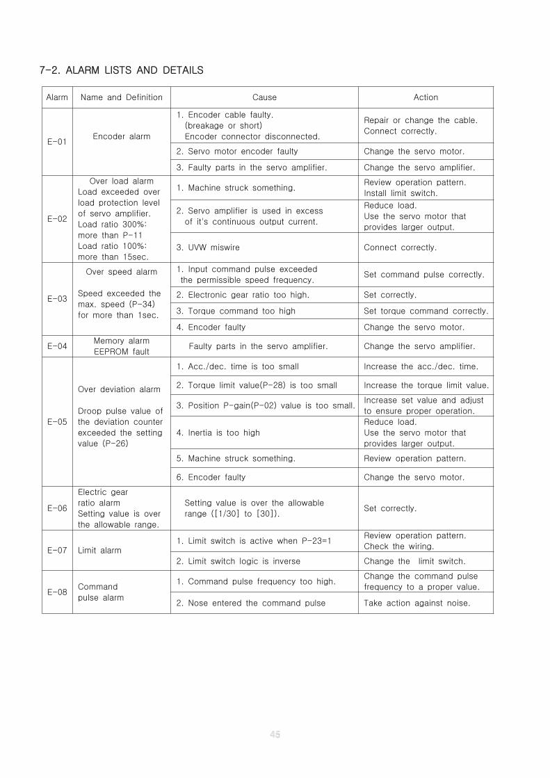
7-2. ALARM LISTS AND DETAILS
Alarm Name and Definition Cause Action
E-01Encoder alarm
1. Encoder cable faulty.
(breakage or short)
Encoder connector disconnected.
Repair or change the cable.
Connect correctly.
2. Servo motor encoder faulty Change the servo motor.
3. Faulty parts in the servo amplifier. Change the servo amplifier.
E-02
Over load alarm
Load exceeded over
load protection level
of servo amplifier.
Load ratio 300%:
more than P-11
Load ratio 100%:
more than 15sec.
1. Machine struck something.Review operation pattern.
Install limit switch.
2. Servo amplifier is used in excess
of it's continuous output current.
Reduce load.
Use the servo motor that
provides larger output.
3. UVW miswire Connect correctly.
E-03
Over speed alarm
Speed exceeded the
max. speed (P-34)
for more than 1sec.
1. Input command pulse exceeded
the permissible speed frequency.Set command pulse correctly.
2. Electronic gear ratio too high. Set correctly.
3. Torque command too high Set torque command correctly.
4. Encoder faulty Change the servo motor.
E-04Memory alarm
EEPROM faultFaulty parts in the servo amplifier. Change the servo amplifier.
E-05
Over deviation alarm
Droop pulse value of
the deviation counter
exceeded the setting
value (P-26)
1. Acc./dec. time is too small Increase the acc./dec. time.
2. Torque limit value(P-28) is too small Increase the torque limit value.
3. Position P-gain(P-02) value is too small.Increase set value and adjust
to ensure proper operation.
4. Inertia is too high
Reduce load.
Use the servo motor that
provides larger output.
5. Machine struck something. Review operation pattern.
6. Encoder faulty Change the servo motor.
E-06
Electric gear
ratio alarm
Setting value is over
the allowable range.
Setting value is over the allowable
range ([1/30] to [30]).Set correctly.
E-07 Limit alarm1. Limit switch is active when P-23=1
Review operation pattern.
Check the wiring.
2. Limit switch logic is inverse Change the limit switch.
E-08Command
pulse alarm
1. Command pulse frequency too high.Change the command pulse
frequency to a proper value.
2. Nose entered the command pulse Take action against noise.
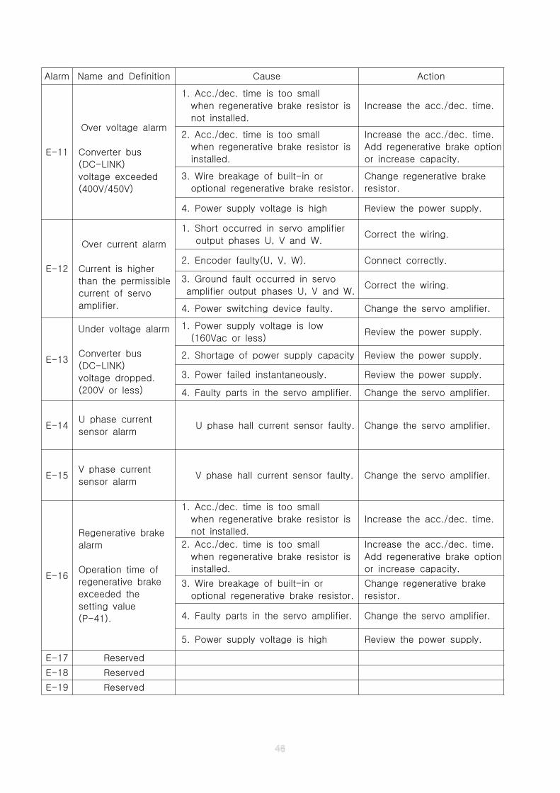
Alarm Name and Definition Cause Action
E-11
Over voltage alarm
Converter bus
(DC-LINK)
voltage exceeded
(400V/450V)
1. Acc./dec. time is too small
when regenerative brake resistor is
not installed.
Increase the acc./dec. time.
2. Acc./dec. time is too small
when regenerative brake resistor is
installed.
Increase the acc./dec. time.
Add regenerative brake option
or increase capacity.
3. Wire breakage of built-in or
optional regenerative brake resistor.
Change regenerative brake
resistor.
4. Power supply voltage is high Review the power supply.
E-12
Over current alarm
Current is higher
than the permissible
current of servo
amplifier.
1. Short occurred in servo amplifier
output phases U, V and W.Correct the wiring.
2. Encoder faulty(U, V, W). Connect correctly.
3. Ground fault occurred in servo
amplifier output phases U, V and W.Correct the wiring.
4. Power switching device faulty. Change the servo amplifier.
E-13
Under voltage alarm
Converter bus
(DC-LINK)
voltage dropped.
(200V or less)
1. Power supply voltage is low
(160Vac or less)Review the power supply.
2. Shortage of power supply capacity Review the power supply.
3. Power failed instantaneously. Review the power supply.
4. Faulty parts in the servo amplifier. Change the servo amplifier.
E-14U phase current
sensor alarmU phase hall current sensor faulty. Change the servo amplifier.
E-15V phase current
sensor alarmV phase hall current sensor faulty. Change the servo amplifier.
E-16
Regenerative brake
alarm
Operation time of
regenerative brake
exceeded the
setting value
(P-41).
1. Acc./dec. time is too small
when regenerative brake resistor is
not installed.
Increase the acc./dec. time.
2. Acc./dec. time is too small
when regenerative brake resistor is
installed.
Increase the acc./dec. time.
Add regenerative brake option
or increase capacity.
3. Wire breakage of built-in or
optional regenerative brake resistor.
Change regenerative brake
resistor.
4. Faulty parts in the servo amplifier. Change the servo amplifier.
5. Power supply voltage is high Review the power supply.
E-17 Reserved
E-18 Reserved
E-19 Reserved
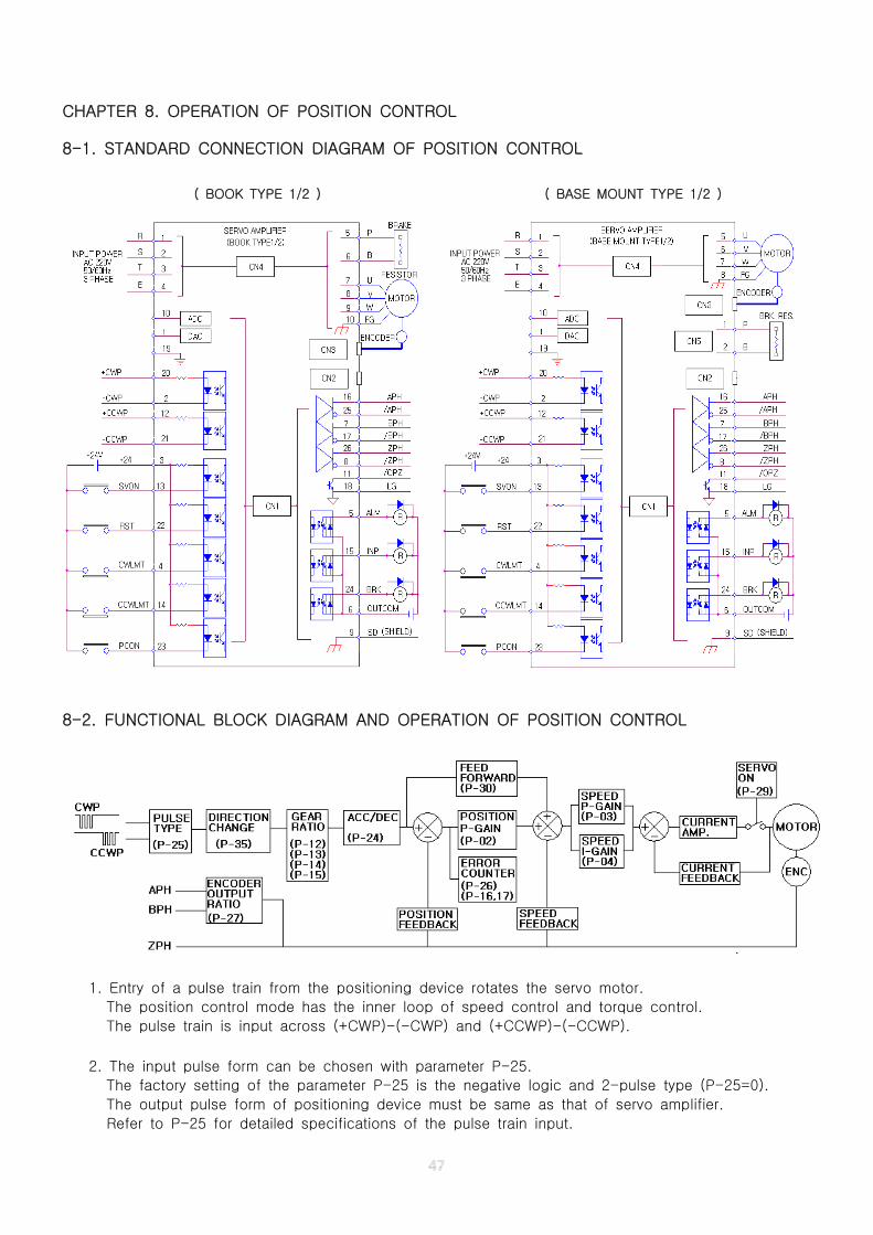
CHAPTER 8. OPERATION OF POSITION CONTROL
8-1. STANDARD CONNECTION DIAGRAM OF POSITION CONTROL
( BOOK TYPE 1/2 ) ( BASE MOUNT TYPE 1/2 )
8-2. FUNCTIONAL BLOCK DIAGRAM AND OPERATION OF POSITION CONTROL
1. Entry of a pulse train from the positioning device rotates the servo motor.
The position control mode has the inner loop of speed control and torque control.
The pulse train is input across (+CWP)-(-CWP) and (+CCWP)-(-CCWP).
2. The input pulse form can be chosen with parameter P-25.
The factory setting of the parameter P-25 is the negative logic and 2-pulse type (P-25=0).
The output pulse form of positioning device must be same as that of servo amplifier.
Refer to P-25 for detailed specifications of the pulse train input.
3. The direction of rotation according to input pulse train is set by parameter P-35.
When the direction of rotation is reverse to the command pulse, the direction of rotation can be
changed by parameter P-35 without hard-wired replacement.
4. Set the electronic gear ratio(parameter P-12,13,14,15), if need be.
The input pulse train can be multiplied by the electronic gear ratio(parameter P-12,13,14,15).
Accordingly, the machine can be moved at any multiplication factor to input pulse.
Refer to P-12,13,14,15 for detailed description.
5. The acceleration and deceleration time is set in parameter P-24, if need be.
In case of the positioning device without acc./dec. function, the pulse train input can be
smoothened in the servo amplifier.
The sine-wave type is the most smoothing method due to the no-break point.
6. Set the gain (position P-gain, speed P-gain, speed I-gain).
The position P-gain, speed P-gain and speed I-gain is set to satisfy no-load condition at
factory setting. Therefore, when the motor is installed to the machine, the gain must be adjusted
to satisfy the load inertia condition. The auto tuning function get the optimal gains (position
P-gain, speed P-gain, speed I-gain) automatically.
When the machine rigidity is low (timing belt or disc without reduction gear), set smaller value
than the normal condition.
(Adjustment of position P-gain)
The position P-gain determines the responsibility of position control.
If the value is bigger, the response is getting better to reduce the position determination time.
However, the high limit value depends upon the response of the machine(inherent frequency)
and rigidity. If the value is too big to make the vibration, there is a acoustic noise in the
mechanical part.
Because the position P-gain is inverse proportional to the load inertia, the gain must be
adjusted to satisfy following formula according to the load inertia. The load inertia is total value
including the motor inertia. Load inertia ratio=(Load inertia+Motor inertia)/Motor inertia
Position P-gain Factory setting value / Load inertia ratio※ ≤
(Adjustment of speed P-gain)
The speed P-gain determines the transient responsibility of speed control.
Because the speed P-gain is directly proportional to the load inertia, the gain must be
adjusted to satisfy following formula according to the load inertia. The load inertia is total value
including the motor inertia.
Speed P-gain Factory setting value X Load inertia ratio※ ≤
(Adjustment of speed I-gain)
The speed I-gain determines the steady state responsibility of speed control.
The bigger the value the better the steady state error. If the value is too big, the transient
overshoot or undershoot is getting bigger, and so it shall be used in the proper range.
Because the speed I-gain is directly proportional to the load friction and is slightly proportional
to load inertia, the gain must be adjusted some highly to the satisfaction of good tuning with
consideration of load friction and inertia. Especially in case of ultra low speed, the intermittent
revolution phenomena disappear due to I-gain of the speed loop.
Speed I-gain = Factory setting value X Load constant※
Load constant (above 1) is the coefficient of load friction and inertia.
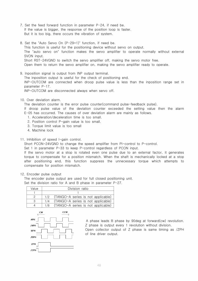
7. Set the feed forward function in parameter P-24, if need be.
If the value is bigger, the response of the position loop is faster.
But it is too big, there occurs the vibration of system.
8. Set the "Auto Servo On (P-29=1)" function, if need be.
This function is useful for the positioning device without servo on output.
The "auto servo on" function makes the servo amplifier to operate normally without external
SVON input.
Short RST-24VGND to switch the servo amplifier off, making the servo motor free.
Open them to return the servo amplifier on, making the servo amplifier ready to operate.
9. Inposition signal is output from INP output terminal.
The inposition output is useful for the check of positioning end.
INP-OUTCOM are connected when droop pulse value is less than the inposition range set in
parameter P-17.
INP-OUTCOM are disconnected always when servo off.
10. Over deviation alarm.
The deviation counter is the error pulse counter(command pulse-feedback pulse).
If droop pulse value of the deviation counter exceeded the setting value then the alarm
E-05 has occurred. The causes of over deviation alarm are mainly as follows.
1. Acceleration/deceleration time is too small.
2. Position control P-gain value is too small.
3. Torque limit value is too small
4. Machine lock
11. Inhibition of speed I-gain control.
Short PCON-24VGND to change the speed amplifier from PI-control to P-control.
Set 1 in parameter P-33 to keep P-control regardless of PCON input.
If the servo motor at a stop is rotated even one pulse due to an external factor, it generates
torque to compensate for a position mismatch. When the shaft is mechanically locked at a stop
after positioning end, this function suppress the unnecessary torque which attempts to
compensate for position mismatch.
12. Encoder pulse output
The encoder pulse output are used for full closed positioning unit.
Set the division ratio for A and B phase in parameter P-27.
A phase leads B phase by 90deg at forward(cw) revolution.
Z phase is output every 1 revolution without division.
Open collector output of Z phase is same timing as /ZPH
of line driver output.
Value Division ratio1 1
2 1/2 (TANGO-A series is not applicable)3 1/4 (TANGO-A series is not applicable)4 1/8 (TANGO-A series is not applicable)
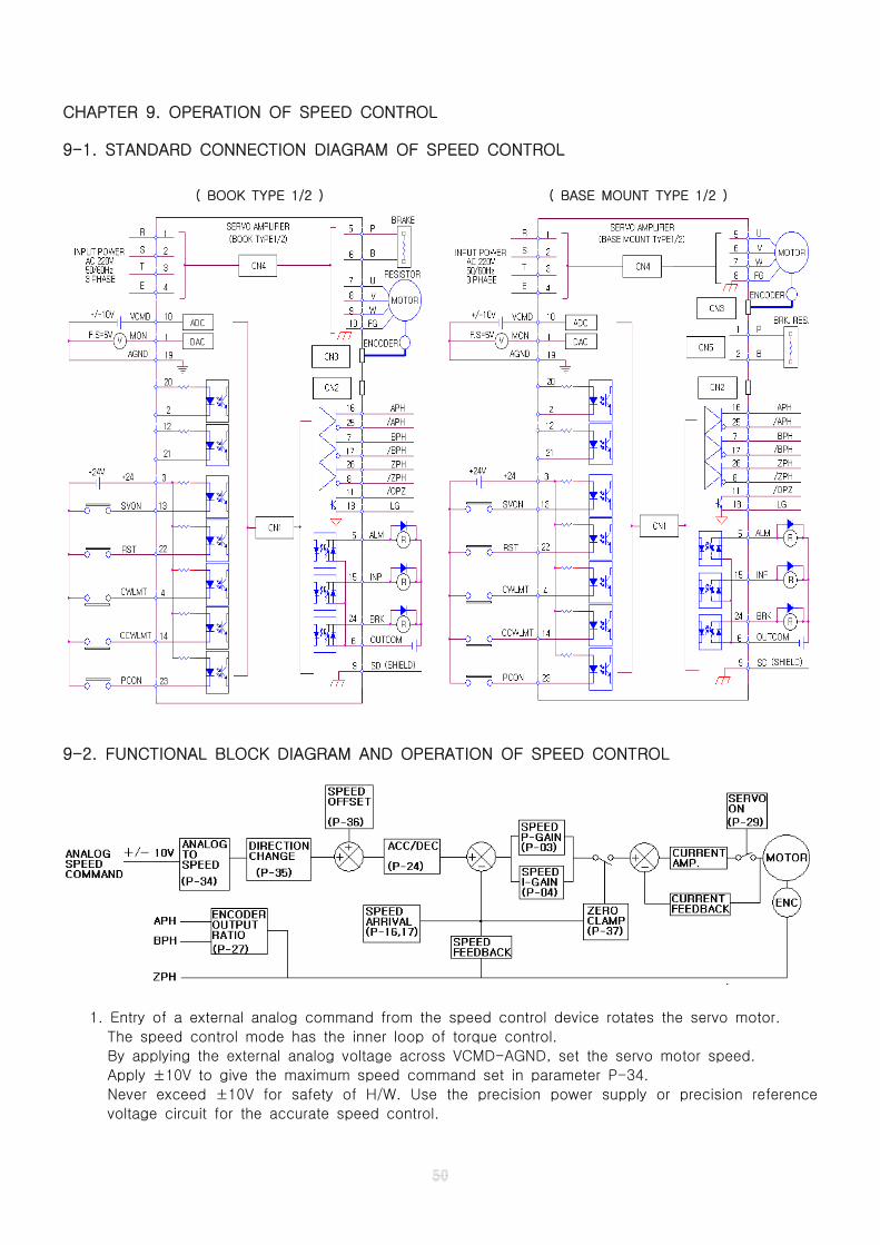
CHAPTER 9. OPERATION OF SPEED CONTROL
9-1. STANDARD CONNECTION DIAGRAM OF SPEED CONTROL
( BOOK TYPE 1/2 ) ( BASE MOUNT TYPE 1/2 )
9-2. FUNCTIONAL BLOCK DIAGRAM AND OPERATION OF SPEED CONTROL
1. Entry of a external analog command from the speed control device rotates the servo motor.
The speed control mode has the inner loop of torque control.
By applying the external analog voltage across VCMD-AGND, set the servo motor speed.
Apply ±10V to give the maximum speed command set in parameter P-34.
Never exceed ±10V for safety of H/W. Use the precision power supply or precision reference
voltage circuit for the accurate speed control.
2. Set the maximum speed range in parameter P-34.
The setting value means the reference speed command matched at 10V which is applied
externally. The factory setting value is applicable for the most operation.
Speed command = ±(analog input voltage X setting value) / 10V※
+: forward revoluton, -: reverse revolution
3. Set the direction of revolution in parameter P-35, if need be.
The direction of revolution according to analog input voltage is set by parameter P-35.
You can change easily the direction of revolution without analog polarity change of command
input.
4. Set the offset speed in parameter P-36, if need be.
The setting value is added to the speed command input for precision speed adjustment.
Speed command = input speed value ± OFFSET※
0~99 +Offset(0~99)
100~199 -Offset(0~99)
5. The acceleration and deceleration time is set in parameter P-24, if need be.
In case of the speed command device without acc./dec. function, the analog input can be
smoothened in the servo amplifier.
The sine-wave type is the most smoothing method due to the no-break point.
6. Set the gain (speed P-gain, speed I-gain).
The speed P-gain and speed I-gain is set to satisfy no-load condition at factory setting.
Therefore, when the motor is installed to the machine, the gain must be adjusted to satisfy the
load inertia condition. The auto tuning function get the optimal gains (speed P-gain, speed
I-gain) automatically.
When the machine rigidity is low (timing belt or disc without reduction gear), set smaller value
than the normal condition.
(Adjustment of speed P-gain)
The speed P-gain determines the transient responsibility of speed control.
Because the speed P-gain is directly proportional to the load inertia, the gain must be
adjusted to satisfy following formula according to the load inertia. The load inertia is total value
including the motor inertia.
Speed P-gain Factory setting value X Load inertia ratio※ ≤
Load inertia ratio=(Load inertia+Motor inertia)/Motor inertia
(Adjustment of speed I-gain)
The speed I-gain determines the steady state responsibility of speed control.
The bigger the value the better the steady state error. If the value is too big, the transient
overshoot or undershoot is getting bigger, and so it shall be used in the proper range.
Because the speed I-gain is directly proportional to the load friction and is slightly proportional
to load inertia, the gain must be adjusted some highly to the satisfaction of good tuning with
consideration of load friction and inertia. Especially in case of ultra low speed, the intermittent
revolution phenomena disappear due to I-gain of the speed loop.
Speed I-gain = Factory setting value X Load constant※
Load constant (above 1) is the coefficient of load friction and inertia.
0 Same direction
1 Opposite direction
7. Set the zero speed clamping function in parameter P-37, if need be.
The analog input does not become 0V completely to remain a little offset. At the time, the servo
motor rotates a little. In order to stop the servo motor completely, use the zero speed clamping
function.
0 Invalid (not used)
More than 1 Valid (the setting value is the reference speed of clamping function.)
8. Set the "Auto Servo On (P-29=1)" function, if need be.
This function is useful for the speed command device without servo on output.
The "auto servo on" function makes the servo amplifier to operate normally without external
SVON input.
Short RST-24VGND to switch the servo amplifier off, making the servo motor free.
Open them to return the servo amplifier on, making the servo amplifier ready to operate.
9. Speed arrival signal is output from INP output terminal.
INP output is used for 2 types of the speed reached signal according to the setting value in
parameter P-16 and P-17. INP-OUTCOM are disconnected always when servo off.
10. Inhibition of speed I-gain control.
Short PCON-24VGND to change the speed amplifier from PI-control to P-control.
Set 1 in parameter P-33 to keep P-control regardless of PCON input.
Sometimes, the operation of repeated abrupt acceleration and deceleration requires only the
P-gain. It performs a fast and good transient response with low steady state speed error.
11. Encoder pulse output
Refer to chapter 8-2-12
0Output on when the servo motor speed is more than
the speed range set in parameter P-17
1Output on when the servo motor speed is less than the
speed range set in parameter P-17
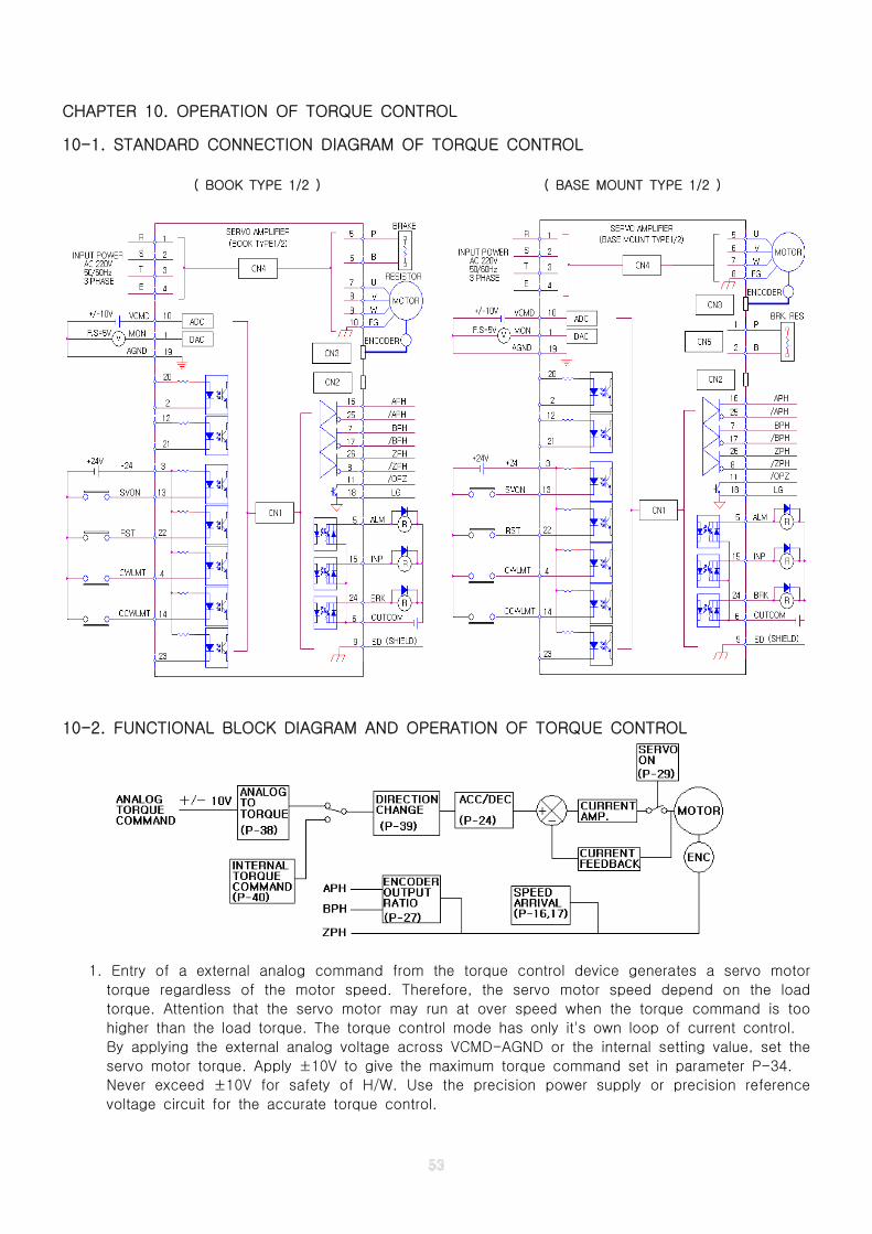
CHAPTER 10. OPERATION OF TORQUE CONTROL
10-1. STANDARD CONNECTION DIAGRAM OF TORQUE CONTROL
( BOOK TYPE 1/2 ) ( BASE MOUNT TYPE 1/2 )
10-2. FUNCTIONAL BLOCK DIAGRAM AND OPERATION OF TORQUE CONTROL
1. Entry of a external analog command from the torque control device generates a servo motor
torque regardless of the motor speed. Therefore, the servo motor speed depend on the load
torque. Attention that the servo motor may run at over speed when the torque command is too
higher than the load torque. The torque control mode has only it's own loop of current control.
By applying the external analog voltage across VCMD-AGND or the internal setting value, set the
servo motor torque. Apply ±10V to give the maximum torque command set in parameter P-34.
Never exceed ±10V for safety of H/W. Use the precision power supply or precision reference
voltage circuit for the accurate torque control.
2. Select the torque command type.
The parameter P-40 decides the torque command type as follows.
3. Set the maximum torque range in parameter P-38 when parameter P-40 is set "0"
The setting value means the reference torque command matched at 10V which is applied
externally. Never apply more than ±10V across VCMD-AGND.
Torque command = ±(analog input voltage X setting value) / 10V※
+: forward torque, -: reverse torque
4. Set the direction of torque in parameter P-39.
External analog torque command(P-40=0): Change easily the direction of torque without analog
polarity change of command input.
0 Same direction
1 Opposite direction
Internal torque command(P-40=1~100): Set the direction of torque in the internal torque
command mode.
0 Forward rotation1 Reverse rotation
5. The acceleration and deceleration time is set in parameter P-24, if need be.
In case of the torque command device without acc./dec. function, the analog input can be
smoothened in the servo amplifier.
The sine-wave type is the most smoothing method due to the no-break point.
6. Set the "Auto Servo On (P-29=1)" function, if need be.
This function is useful for the torque command device without servo on output.
The "auto servo on" function makes the servo amplifier to operate normally without external
SVON input.
Short RST-24VGND to switch the servo amplifier off, making the servo motor free.
Open them to return the servo amplifier on, making the servo amplifier ready to operate.
7. Speed arrival signal is output from INP output terminal.
INP output is used for 2 types of the speed reached signal according to the setting value in
parameter P-16 and P-17. INP-OUTCOM are disconnected always when servo off.
8. Encoder pulse output
Refer to chapter 8-2-12
0External analog torque command mode is available
The maximum torque command equivalent to 10V is set in parameter P-38.
More than 1Setting value is used for the internal torque command
The unit is % of the rated torque
0Output on when the servo motor speed is more than
the speed range set in parameter P-17
1Output on when the servo motor speed is less than
the speed range set in parameter P-17
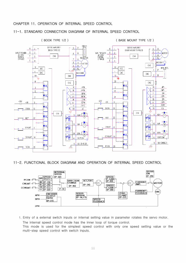
CHAPTER 11. OPERATION OF INTERNAL SPEED CONTROL
11-1. STANDARD CONNECTION DIAGRAM OF INTERNAL SPEED CONTROL
( BOOK TYPE 1/2 ) ( BASE MOUNT TYPE 1/2 )
11-2. FUNCTIONAL BLOCK DIAGRAM AND OPERATION OF INTERNAL SPEED CONTROL
1. Entry of a external switch inputs or internal setting value in parameter rotates the servo motor.
The internal speed control mode has the inner loop of torque control.
This mode is used for the simplest speed control with only one speed setting value or the
multi-step speed control with switch inputs.
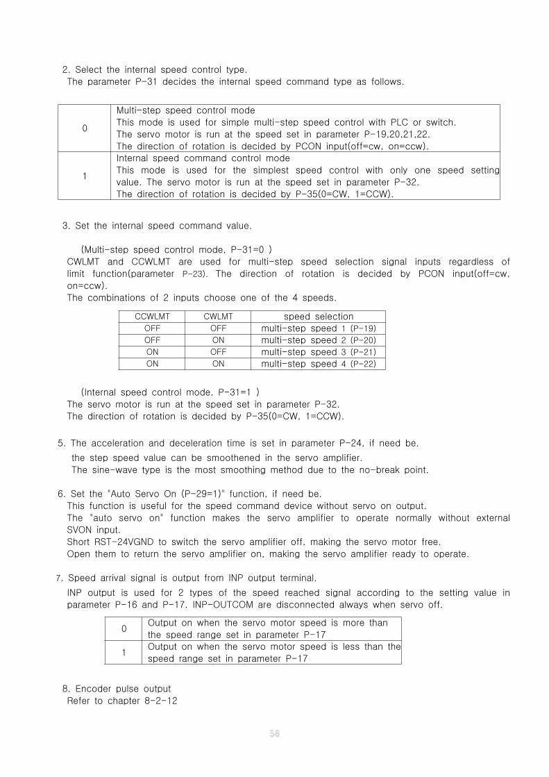
2. Select the internal speed control type.
The parameter P-31 decides the internal speed command type as follows.
3. Set the internal speed command value.
(Multi-step speed control mode, P-31=0 )
CWLMT and CCWLMT are used for multi-step speed selection signal inputs regardless of
limit function(parameter P-23). The direction of rotation is decided by PCON input(off=cw,
on=ccw).
The combinations of 2 inputs choose one of the 4 speeds.
(Internal speed control mode, P-31=1 )
The servo motor is run at the speed set in parameter P-32.
The direction of rotation is decided by P-35(0=CW, 1=CCW).
5. The acceleration and deceleration time is set in parameter P-24, if need be.
the step speed value can be smoothened in the servo amplifier.
The sine-wave type is the most smoothing method due to the no-break point.
6. Set the "Auto Servo On (P-29=1)" function, if need be.
This function is useful for the speed command device without servo on output.
The "auto servo on" function makes the servo amplifier to operate normally without external
SVON input.
Short RST-24VGND to switch the servo amplifier off, making the servo motor free.
Open them to return the servo amplifier on, making the servo amplifier ready to operate.
7. Speed arrival signal is output from INP output terminal.
INP output is used for 2 types of the speed reached signal according to the setting value in
parameter P-16 and P-17. INP-OUTCOM are disconnected always when servo off.
8. Encoder pulse output
Refer to chapter 8-2-12
0
Multi-step speed control mode
This mode is used for simple multi-step speed control with PLC or switch.
The servo motor is run at the speed set in parameter P-19,20,21,22.
The direction of rotation is decided by PCON input(off=cw, on=ccw).
1
Internal speed command control mode
This mode is used for the simplest speed control with only one speed setting
value. The servo motor is run at the speed set in parameter P-32.
The direction of rotation is decided by P-35(0=CW, 1=CCW).
CCWLMT CWLMT speed selectionOFF OFF multi-step speed 1 (P-19)
OFF ON multi-step speed 2 (P-20)
ON OFF multi-step speed 3 (P-21)
ON ON multi-step speed 4 (P-22)
0Output on when the servo motor speed is more than
the speed range set in parameter P-17
1Output on when the servo motor speed is less than the
speed range set in parameter P-17
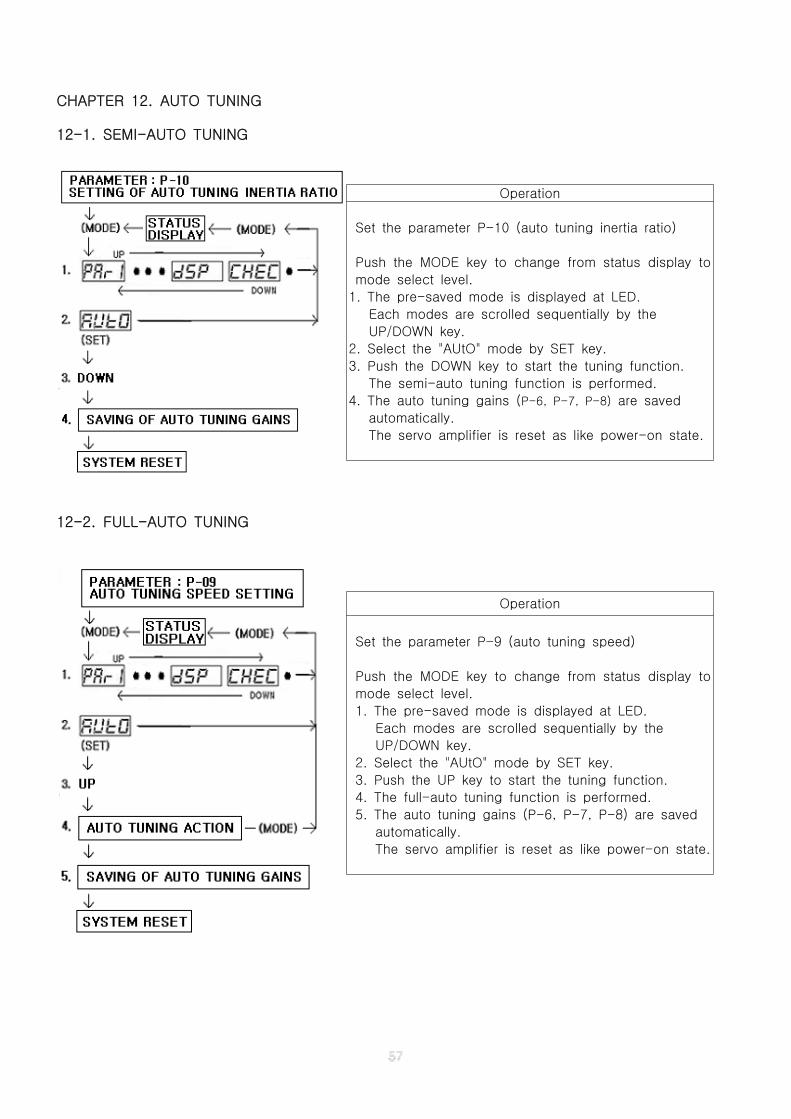
CHAPTER 12. AUTO TUNING
12-1. SEMI-AUTO TUNING
12-2. FULL-AUTO TUNING
Operation
Set the parameter P-10 (auto tuning inertia ratio)
Push the MODE key to change from status display to
mode select level.
1. The pre-saved mode is displayed at LED.
Each modes are scrolled sequentially by the
UP/DOWN key.
2. Select the "AUtO" mode by SET key.
3. Push the DOWN key to start the tuning function.
The semi-auto tuning function is performed.
4. The auto tuning gains (P-6, P-7, P-8) are saved
automatically.
The servo amplifier is reset as like power-on state.
Operation
Set the parameter P-9 (auto tuning speed)
Push the MODE key to change from status display to
mode select level.
1. The pre-saved mode is displayed at LED.
Each modes are scrolled sequentially by the
UP/DOWN key.
2. Select the "AUtO" mode by SET key.
3. Push the UP key to start the tuning function.
4. The full-auto tuning function is performed.
5. The auto tuning gains (P-6, P-7, P-8) are saved
automatically.
The servo amplifier is reset as like power-on state.
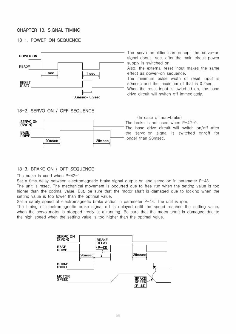
CHAPTER 13. SIGNAL TIMING
13-1. POWER ON SEQUENCE
The servo amplifier can accept the servo-on
signal about 1sec. after the main circuit power
supply is switched on.
Also, the external reset input makes the same
effect as power-on sequence.
The minimum pulse width of reset input is
50msec and the maximum of that is 0.2sec.
When the reset input is switched on, the base
drive circuit will switch off immediately.
13-2. SERVO ON / OFF SEQUENCE
(In case of non-brake)
The brake is not used when P-42=0.
The base drive circuit will switch on/off after
the servo-on signal is switched on/off for
longer than 20msec.
13-3. BRAKE ON / OFF SEQUENCE
The brake is used when P-42=1.
Set a time delay between electromagnetic brake signal output on and servo on in parameter P-43.
The unit is msec. The mechanical movement is occurred due to free-run when the setting value is too
higher than the optimal value. But, be sure that the motor shaft is damaged due to locking when the
setting value is too lower than the optimal value.
Set a safety speed of electromagnetic brake action in parameter P-44. The unit is rpm.
The timing of electromagnetic brake signal off is delayed until the speed reaches the setting value,
when the servo motor is stopped freely at a running. Be sure that the motor shaft is damaged due to
the high speed when the setting value is too higher than the optimal value.
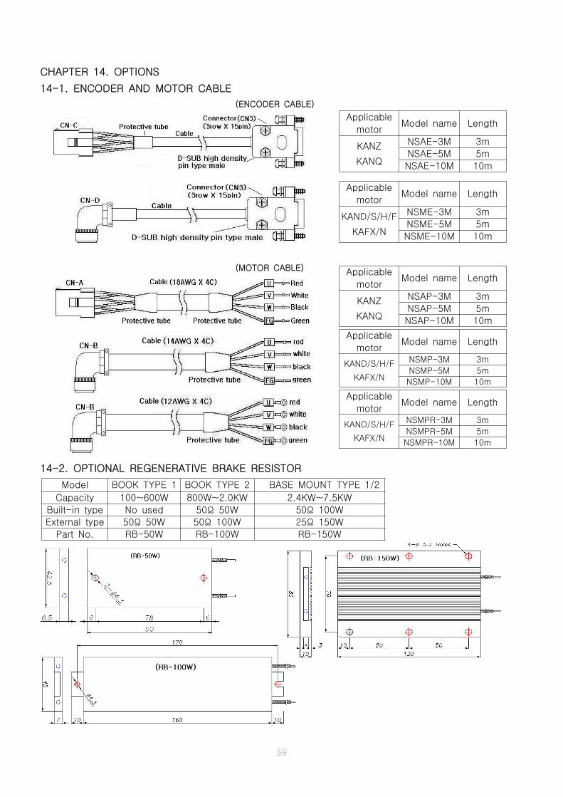
CHAPTER 14. OPTIONS
14-1. ENCODER AND MOTOR CABLE
(ENCODER CABLE)
(MOTOR CABLE)
14-2. OPTIONAL REGENERATIVE BRAKE RESISTOR
Applicable
motorModel name Length
KANZ
KANQ
NSAE-3M 3m
NSAE-5M 5m
NSAE-10M 10m
Applicable
motorModel name Length
KAND/S/H/F
KAFX/N
NSME-3M 3m
NSME-5M 5m
NSME-10M 10m
Applicable
motorModel name Length
KANZ
KANQ
NSAP-3M 3m
NSAP-5M 5m
NSAP-10M 10m
Applicable
motorModel name Length
KAND/S/H/F
KAFX/N
NSMP-3M 3m
NSMP-5M 5m
NSMP-10M 10m
Model BOOK TYPE 1 BOOK TYPE 2 BASE MOUNT TYPE 1/2
Capacity 100~600W 800W~2.0KW 2.4KW~7.5KW
Built-in type No used 50 50WΩ 50 100WΩ
External type 50 50WΩ 50 100WΩ 25 150WΩ
Part No. RB-50W RB-100W RB-150W
Applicable
motorModel name Length
KAND/S/H/F
KAFX/N
NSMPR-3M 3m
NSMPR-5M 5m
NSMPR-10M 10m
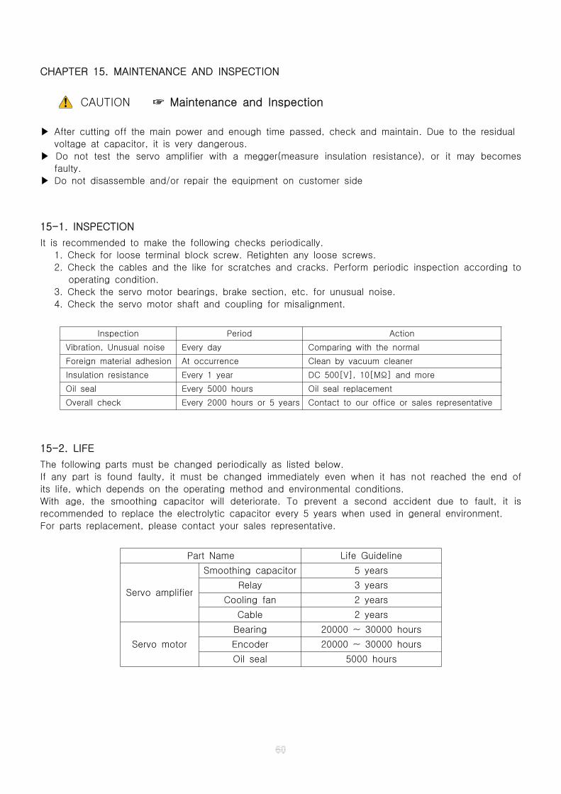
CHAPTER 15. MAINTENANCE AND INSPECTION
CAUTION Maintenance and Inspection☞
▶ After cutting off the main power and enough time passed, check and maintain. Due to the residual
voltage at capacitor, it is very dangerous.
▶ Do not test the servo amplifier with a megger(measure insulation resistance), or it may becomes
faulty.
▶ Do not disassemble and/or repair the equipment on customer side
15-1. INSPECTION
It is recommended to make the following checks periodically.
1. Check for loose terminal block screw. Retighten any loose screws.
2. Check the cables and the like for scratches and cracks. Perform periodic inspection according to
operating condition.
3. Check the servo motor bearings, brake section, etc. for unusual noise.
4. Check the servo motor shaft and coupling for misalignment.
Inspection Period Action
Vibration, Unusual noise Every day Comparing with the normal
Foreign material adhesion At occurrence Clean by vacuum cleaner
Insulation resistance Every 1 year DC 500[V], 10[M ] and moreΩ
Oil seal Every 5000 hours Oil seal replacement
Overall check Every 2000 hours or 5 years Contact to our office or sales representative
15-2. LIFE
The following parts must be changed periodically as listed below.
If any part is found faulty, it must be changed immediately even when it has not reached the end of
its life, which depends on the operating method and environmental conditions.
With age, the smoothing capacitor will deteriorate. To prevent a second accident due to fault, it is
recommended to replace the electrolytic capacitor every 5 years when used in general environment.
For parts replacement, please contact your sales representative.
Part Name Life Guideline
Servo amplifier
Smoothing capacitor 5 years
Relay 3 years
Cooling fan 2 years
Cable 2 years
Servo motor
Bearing 20000 ~ 30000 hours
Encoder 20000 ~ 30000 hours
Oil seal 5000 hours

CHAPTER 16. SUMMARY OF LISTS
16-1. PARAMETER LISTS
( P: position S: speed T: torque I: internal speed )
Group No. NameRange Control mode
Min Max P S T I
PAR1
00 Control mode selection 0 3 ☑ ☑ ☑ ☑01 Gain selection 0 1 ☑ ☑ ☑02 Position P(proportional) gain 1 1000 ☑03 Speed P(proportional) gain 1 1000 ☑ ☑ ☑04 Speed I(integral) gain 1 1000 ☑ ☑ ☑05 Reserved 1 1000
06 Auto tuning position P(proportional) gain 1 1000 ☑07 Auto tuning speed P(proportional) gain 1 1000 ☑ ☑ ☑08 Auto tuning speed I(integral) gain 1 1000 ☑ ☑ ☑09 Auto tuning speed 200 2000
10 Auto tuning inertia ratio 1 9999
11 Over load time 1 30 ☑ ☑ ☑12 Electronic gear denominator1 (1000's) 1 9999 ☑13 Electronic gear numerator1 (1000's) 1 9999 ☑14 Electronic gear denominator2 (10000's) 0 2 ☑15 Electronic gear numerator2 (10000's) 0 2 ☑16 Inposition output type 0 1 ☑ ☑ ☑ ☑17 Speed arrival reference 1 5000 ☑ ☑ ☑ ☑18 Analog monitor type 0 1 ☑ ☑ ☑ ☑19 Multi-step speed 1 1 5000 ☑20 Multi-step speed 2 1 5000 ☑21 Multi-step speed 3 1 5000 ☑22 Multi-step speed 4 1 5000 ☑23 Limit function use 0 1 ☑ ☑ ☑ ☑
PAR2
24 Acceleration/deceleration time 0 2150 ☑ ☑ ☑ ☑25 Pulse train input type 0 5 ☑26 Over deviation pulse 200 9999 ☑27 Encoder output division ratio 1 4 ☑ ☑ ☑ ☑28 Maximum torque limit 10 300 ☑ ☑ ☑29 Auto servo on 0 1 ☑ ☑ ☑ ☑30 Feed forward gain 0 1000 ☑31 Internal speed type 0 1 ☑32 Internal speed 1 5000 ☑33 Speed I gain inhibition 0 1 ☑ ☑ ☑34 Maximum speed 1000 5000 ☑ ☑ ☑ ☑35 Command direction 0 1 ☑ ☑ ☑36 Speed command offset 0 199 ☑37 Zero speed clamping 0 200 ☑ ☑38 Maximum torque command 0 100 ☑39 Torque command direction 0 1 ☑40 Torque command type 0 100 ☑41 Regeneration brake time 0 3 ☑ ☑ ☑ ☑42 Brake output use 0 1 ☑ ☑ ☑ ☑43 Brake on delay time 10 500 ☑ ☑ ☑ ☑44 Brake off speed 1 300 ☑ ☑ ☑ ☑45 Test run speed 1 5000
46 Baud rate 0 9
47 Device ID 0 255
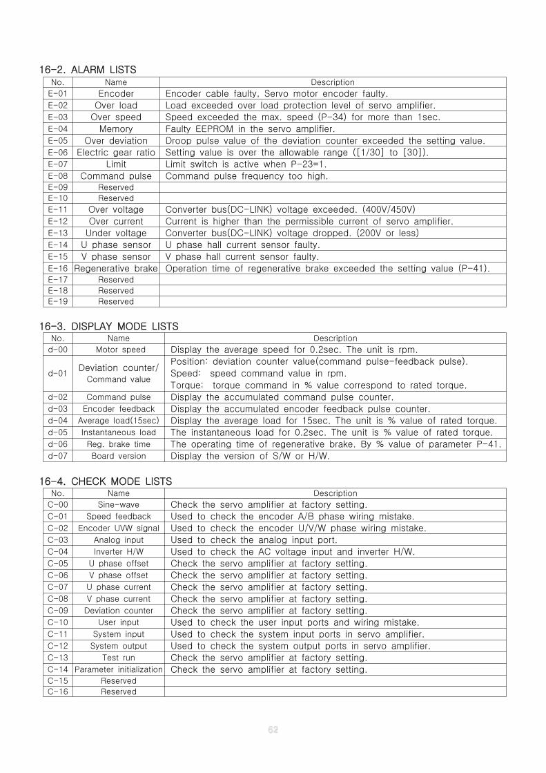
16-2. ALARM LISTS
16-3. DISPLAY MODE LISTS
16-4. CHECK MODE LISTS
No. Name Description
E-01 Encoder Encoder cable faulty, Servo motor encoder faulty.E-02 Over load Load exceeded over load protection level of servo amplifier.E-03 Over speed Speed exceeded the max. speed (P-34) for more than 1sec.E-04 Memory Faulty EEPROM in the servo amplifier.E-05 Over deviation Droop pulse value of the deviation counter exceeded the setting value.E-06 Electric gear ratio Setting value is over the allowable range ([1/30] to [30]).E-07 Limit Limit switch is active when P-23=1.E-08 Command pulse Command pulse frequency too high.E-09 Reserved
E-10 Reserved
E-11 Over voltage Converter bus(DC-LINK) voltage exceeded. (400V/450V)E-12 Over current Current is higher than the permissible current of servo amplifier.E-13 Under voltage Converter bus(DC-LINK) voltage dropped. (200V or less)E-14 U phase sensor U phase hall current sensor faulty.E-15 V phase sensor V phase hall current sensor faulty.E-16 Regenerative brake Operation time of regenerative brake exceeded the setting value (P-41).E-17 Reserved
E-18 Reserved
E-19 Reserved
No. Name Description
d-00 Motor speed Display the average speed for 0.2sec. The unit is rpm.
d-01Deviation counter/
Command value
Position: deviation counter value(command pulse-feedback pulse).
Speed: speed command value in rpm.
Torque: torque command in % value correspond to rated torque.d-02 Command pulse Display the accumulated command pulse counter.d-03 Encoder feedback Display the accumulated encoder feedback pulse counter.d-04 Average load(15sec) Display the average load for 15sec. The unit is % value of rated torque.d-05 Instantaneous load The instantaneous load for 0.2sec. The unit is % value of rated torque.d-06 Reg. brake time The operating time of regenerative brake. By % value of parameter P-41.d-07 Board version Display the version of S/W or H/W.
No. Name Description
C-00 Sine-wave Check the servo amplifier at factory setting.C-01 Speed feedback Used to check the encoder A/B phase wiring mistake.C-02 Encoder UVW signal Used to check the encoder U/V/W phase wiring mistake.C-03 Analog input Used to check the analog input port.C-04 Inverter H/W Used to check the AC voltage input and inverter H/W.C-05 U phase offset Check the servo amplifier at factory setting.C-06 V phase offset Check the servo amplifier at factory setting.C-07 U phase current Check the servo amplifier at factory setting.C-08 V phase current Check the servo amplifier at factory setting.C-09 Deviation counter Check the servo amplifier at factory setting.C-10 User input Used to check the user input ports and wiring mistake.C-11 System input Used to check the system input ports in servo amplifier.C-12 System output Used to check the system output ports in servo amplifier.C-13 Test run Check the servo amplifier at factory setting.C-14 Parameter initialization Check the servo amplifier at factory setting.C-15 Reserved
C-16 Reserved
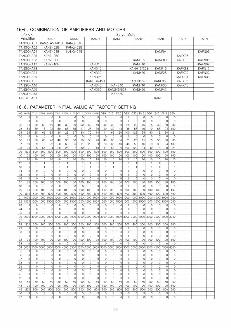
16-5. COMBINATION OF AMPLIFIERS AND MOTORS
16-6. PARAMETER INITIAL VALUE AT FACTORY SETTING
NO ZA5B Z01B Z02B Z04B Z06B Z08B Z10B Q01B Q02B Q04B D10 D15 D20 D25 D30 D45 D50 S40 S45 S50
00 0 0 0 0 0 0 0 0 0 0 0 0 0 0 0 0 0 0 0 0
01 0 0 0 0 0 0 0 0 0 0 0 0 0 0 0 0 0 0 0 0
02 90 60 60 40 40 30 30 60 50 40 40 35 30 25 20 15 15 30 30 30
03 69 59 16 22 50 66 65 11 26 39 20 32 43 48 58 16 19 86 94 100
04 29 25 66 94 20 28 27 30 70 110 41 68 90 100 122 34 40 18 20 21
05 0 0 0 0 0 0 0 0 0 0 0 0 0 0 0 0 0 0 0 0
06 90 60 60 40 40 30 30 50 50 40 40 35 30 25 20 15 15 30 30 30
07 69 59 16 22 50 66 65 11 26 39 20 32 43 48 58 16 19 86 94 100
08 29 25 66 94 20 28 27 30 70 110 41 68 90 100 122 34 40 18 20 21
09 500 500 500 500 500 500 500 500 500 500 500 500 500 500 500 500 500 500 500 500
10 100 100 100 100 100 100 100 100 100 100 100 100 100 100 100 100 100 100 100 100
11 10 10 10 10 10 10 10 10 10 10 10 10 10 10 10 10 10 10 10 10
12 1 1 1 1 1 1 1 1 1 1 1 1 1 1 1 1 1 1 1 1
13 1 1 1 1 1 1 1 1 1 1 1 1 1 1 1 1 1 1 1 1
14 0 0 0 0 0 0 0 0 0 0 0 0 0 0 0 0 0 0 0 0
15 0 0 0 0 0 0 0 0 0 0 0 0 0 0 0 0 0 0 0 0
16 0 0 0 0 0 0 0 0 0 0 0 0 0 0 0 0 0 0 0 0
17 100 100 100 100 100 100 100 100 100 100 100 100 100 100 100 100 100 100 100 100
18 0 0 0 0 0 0 0 0 0 0 0 0 0 0 0 0 0 0 0 0
19 100 100 100 100 100 100 100 100 100 100 100 100 100 100 100 100 100 100 100 100
20 500 500 500 500 500 500 500 500 500 500 500 500 500 500 500 500 500 500 500 500
21 1000 1000 1000 1000 1000 1000 1000 1000 1000 1000 1000 1000 1000 1000 1000 1000 1000 1000 1000 1000
22 1500 1500 1500 1500 1500 1500 1500 1500 1500 1500 1500 1500 1500 1500 1500 1500 1500 1500 1500 1500
23 0 0 0 0 0 0 0 0 0 0 0 0 0 0 0 0 0 0 0 0
24 0 0 0 0 0 0 0 0 0 0 0 0 0 0 0 0 0 0 0 0
25 0 0 0 0 0 0 0 0 0 0 0 0 0 0 0 0 0 0 0 0
26 3000 3000 3000 3000 3000 3000 3000 3000 3000 3000 3000 3000 3000 3000 3000 3000 3000 3000 3000 3000
27 1 1 1 1 1 1 1 1 1 1 1 1 1 1 1 1 1 1 1 1
28 300 300 300 300 300 300 300 300 300 300 300 300 300 300 300 300 300 300 300 300
29 0 0 0 0 0 0 0 0 0 0 0 0 0 0 0 0 0 0 0 0
30 0 0 0 0 0 0 0 0 0 0 0 0 0 0 0 0 0 0 0 0
31 0 0 0 0 0 0 0 0 0 0 0 0 0 0 0 0 0 0 0 0
32 100 100 100 100 100 100 100 100 100 100 100 100 100 100 100 100 100 100 100 100
33 0 0 0 0 0 0 0 0 0 0 0 0 0 0 0 0 0 0 0 0
34 5000 5000 5000 5000 4500 4500 3500 5000 5000 5000 3000 3000 3000 3000 3000 3000 3000 4500 4500 4500
35 0 0 0 0 0 0 0 0 0 0 0 0 0 0 0 0 0 0 0 0
36 0 0 0 0 0 0 0 0 0 0 0 0 0 0 0 0 0 0 0 0
37 0 0 0 0 0 0 0 0 0 0 0 0 0 0 0 0 0 0 0 0
38 0 0 0 0 0 0 0 0 0 0 0 0 0 0 0 0 0 0 0 0
39 0 0 0 0 0 0 0 0 0 0 0 0 0 0 0 0 0 0 0 0
40 0 0 0 0 0 0 0 0 0 0 0 0 0 0 0 0 0 0 0 0
41 0 0 0 0 0 0 0 0 0 0 0 0 0 0 0 0 0 0 0 0
42 0 0 0 0 0 0 0 0 0 0 0 0 0 0 0 0 0 0 0 0
43 50 50 50 50 50 50 50 50 50 50 50 50 50 50 50 50 50 50 50 50
44 100 100 100 100 100 100 100 100 100 100 100 100 100 100 100 100 100 100 100 100
45 500 500 500 500 500 500 500 500 500 500 500 500 500 500 500 500 500 500 500 500
46 3 3 3 3 3 3 3 3 3 3 3 3 3 3 3 3 3 3 3 3
47 0 0 0 0 0 0 0 0 0 0 0 0 0 0 0 0 0 0 0 0
ServoAmplifier
Servo MotorKANZ KANQ KAND KANS KANH KANF KAFX KAFN
TANGO-A01 KANZ-A5B/01B KANQ-01B
TANGO-A02 KANZ-02B KANQ-02B
TANGO-A04 KANZ-04B KANQ-04B KANF04 KAFN03
TANGO-A06 KANZ-06B KAFX05
TANGO-A08 KANZ-08B KANH05 KANF08 KAFX09 KAFN06
TANGO-A12 KANZ-10B KAND10 KANH10 KAFN09
TANGO-A18 KAND15 KANH15/20S KANF15 KAFX13 KAFN12
TANGO-A24 KAND20 KANH20 KANF25 KAFX20 KAFN20
TANGO-A30 KAND25 KAFX30S KAFN30
TANGO-A35 KAND30/45S KANH30/40S KANF35S KAFX30
TANGO-A40 KAND45 KANS40 KANH40 KANF35 KAFX45
TANGO-A50 KAND50 KANS45/50S KANH50 KANF45
TANGO-A75 KANS50
TANGO-AH1 KANF110
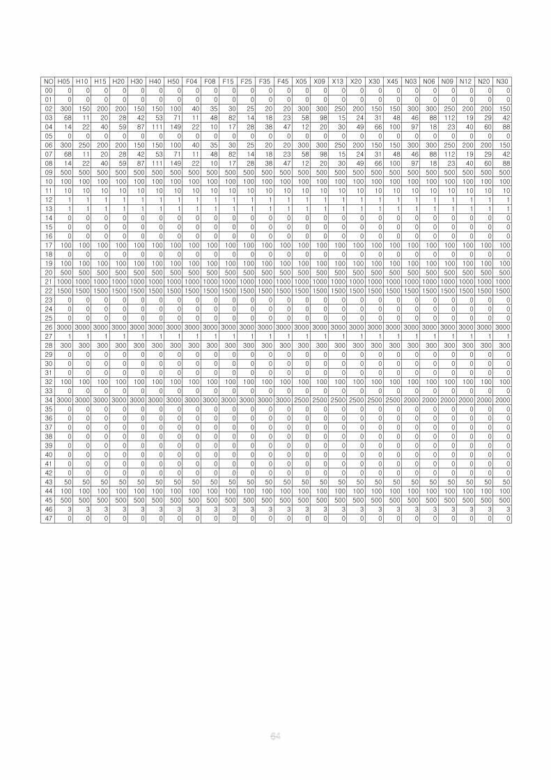
NO H05 H10 H15 H20 H30 H40 H50 F04 F08 F15 F25 F35 F45 X05 X09 X13 X20 X30 X45 N03 N06 N09 N12 N20 N30
00 0 0 0 0 0 0 0 0 0 0 0 0 0 0 0 0 0 0 0 0 0 0 0 0 0
01 0 0 0 0 0 0 0 0 0 0 0 0 0 0 0 0 0 0 0 0 0 0 0 0 0
02 300 150 200 200 150 150 100 40 35 30 25 20 20 300 300 250 200 150 150 300 300 250 200 200 150
03 68 11 20 28 42 53 71 11 48 82 14 18 23 58 98 15 24 31 48 46 88 112 19 29 42
04 14 22 40 59 87 111 149 22 10 17 28 38 47 12 20 30 49 66 100 97 18 23 40 60 88
05 0 0 0 0 0 0 0 0 0 0 0 0 0 0 0 0 0 0 0 0 0 0 0 0 0
06 300 250 200 200 150 150 100 40 35 30 25 20 20 300 300 250 200 150 150 300 300 250 200 200 150
07 68 11 20 28 42 53 71 11 48 82 14 18 23 58 98 15 24 31 48 46 88 112 19 29 42
08 14 22 40 59 87 111 149 22 10 17 28 38 47 12 20 30 49 66 100 97 18 23 40 60 88
09 500 500 500 500 500 500 500 500 500 500 500 500 500 500 500 500 500 500 500 500 500 500 500 500 500
10 100 100 100 100 100 100 100 100 100 100 100 100 100 100 100 100 100 100 100 100 100 100 100 100 100
11 10 10 10 10 10 10 10 10 10 10 10 10 10 10 10 10 10 10 10 10 10 10 10 10 10
12 1 1 1 1 1 1 1 1 1 1 1 1 1 1 1 1 1 1 1 1 1 1 1 1 1
13 1 1 1 1 1 1 1 1 1 1 1 1 1 1 1 1 1 1 1 1 1 1 1 1 1
14 0 0 0 0 0 0 0 0 0 0 0 0 0 0 0 0 0 0 0 0 0 0 0 0 0
15 0 0 0 0 0 0 0 0 0 0 0 0 0 0 0 0 0 0 0 0 0 0 0 0 0
16 0 0 0 0 0 0 0 0 0 0 0 0 0 0 0 0 0 0 0 0 0 0 0 0 0
17 100 100 100 100 100 100 100 100 100 100 100 100 100 100 100 100 100 100 100 100 100 100 100 100 100
18 0 0 0 0 0 0 0 0 0 0 0 0 0 0 0 0 0 0 0 0 0 0 0 0 0
19 100 100 100 100 100 100 100 100 100 100 100 100 100 100 100 100 100 100 100 100 100 100 100 100 100
20 500 500 500 500 500 500 500 500 500 500 500 500 500 500 500 500 500 500 500 500 500 500 500 500 500
21 1000 1000 1000 1000 1000 1000 1000 1000 1000 1000 1000 1000 1000 1000 1000 1000 1000 1000 1000 1000 1000 1000 1000 1000 1000
22 1500 1500 1500 1500 1500 1500 1500 1500 1500 1500 1500 1500 1500 1500 1500 1500 1500 1500 1500 1500 1500 1500 1500 1500 1500
23 0 0 0 0 0 0 0 0 0 0 0 0 0 0 0 0 0 0 0 0 0 0 0 0 0
24 0 0 0 0 0 0 0 0 0 0 0 0 0 0 0 0 0 0 0 0 0 0 0 0 0
25 0 0 0 0 0 0 0 0 0 0 0 0 0 0 0 0 0 0 0 0 0 0 0 0 0
26 3000 3000 3000 3000 3000 3000 3000 3000 3000 3000 3000 3000 3000 3000 3000 3000 3000 3000 3000 3000 3000 3000 3000 3000 3000
27 1 1 1 1 1 1 1 1 1 1 1 1 1 1 1 1 1 1 1 1 1 1 1 1 1
28 300 300 300 300 300 300 300 300 300 300 300 300 300 300 300 300 300 300 300 300 300 300 300 300 300
29 0 0 0 0 0 0 0 0 0 0 0 0 0 0 0 0 0 0 0 0 0 0 0 0 0
30 0 0 0 0 0 0 0 0 0 0 0 0 0 0 0 0 0 0 0 0 0 0 0 0 0
31 0 0 0 0 0 0 0 0 0 0 0 0 0 0 0 0 0 0 0 0 0 0 0 0 0
32 100 100 100 100 100 100 100 100 100 100 100 100 100 100 100 100 100 100 100 100 100 100 100 100 100
33 0 0 0 0 0 0 0 0 0 0 0 0 0 0 0 0 0 0 0 0 0 0 0 0 0
34 3000 3000 3000 3000 3000 3000 3000 3000 3000 3000 3000 3000 3000 2500 2500 2500 2500 2500 2500 2000 2000 2000 2000 2000 2000
35 0 0 0 0 0 0 0 0 0 0 0 0 0 0 0 0 0 0 0 0 0 0 0 0 0
36 0 0 0 0 0 0 0 0 0 0 0 0 0 0 0 0 0 0 0 0 0 0 0 0 0
37 0 0 0 0 0 0 0 0 0 0 0 0 0 0 0 0 0 0 0 0 0 0 0 0 0
38 0 0 0 0 0 0 0 0 0 0 0 0 0 0 0 0 0 0 0 0 0 0 0 0 0
39 0 0 0 0 0 0 0 0 0 0 0 0 0 0 0 0 0 0 0 0 0 0 0 0 0
40 0 0 0 0 0 0 0 0 0 0 0 0 0 0 0 0 0 0 0 0 0 0 0 0 0
41 0 0 0 0 0 0 0 0 0 0 0 0 0 0 0 0 0 0 0 0 0 0 0 0 0
42 0 0 0 0 0 0 0 0 0 0 0 0 0 0 0 0 0 0 0 0 0 0 0 0 0
43 50 50 50 50 50 50 50 50 50 50 50 50 50 50 50 50 50 50 50 50 50 50 50 50 50
44 100 100 100 100 100 100 100 100 100 100 100 100 100 100 100 100 100 100 100 100 100 100 100 100 100
45 500 500 500 500 500 500 500 500 500 500 500 500 500 500 500 500 500 500 500 500 500 500 500 500 500
46 3 3 3 3 3 3 3 3 3 3 3 3 3 3 3 3 3 3 3 3 3 3 3 3 3
47 0 0 0 0 0 0 0 0 0 0 0 0 0 0 0 0 0 0 0 0 0 0 0 0 0
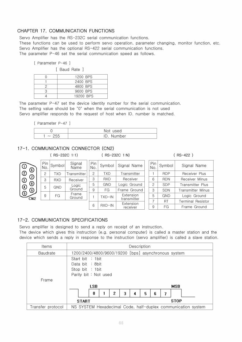
CHAPTER 17. COMMUNICATION FUNCTIONS
Servo Amplifier has the RS-232C serial communication functions.
These functions can be used to perform servo operation, parameter changing, monitor function, etc.
Servo Amplifier has the optional RS-422 serial communication functions.
The parameter P-46 set the serial communication speed as follows.
[ Parameter P-46 ]
[ Baud Rate ]
0 1200 BPS
1 2400 BPS
2 4800 BPS
3 9600 BPS
4 19200 BPS
The parameter P-47 set the device identity number for the serial communication.
The setting value should be "0" when the serial communication is not used
Servo amplifier responds to the request of host when ID. number is matched.
[ Parameter P-47 ]
0 Not used
1 ~ 255 ID. Number
17-1. COMMUNICATION CONNECTOR (CN2)
( RS-232C 1:1) ( RS-232C 1:N) ( RS-422 )
17-2. COMMUNICATION SPECIFICATIONS
Servo amplifier is designed to send a reply on receipt of an instruction.
The device which gives this instruction (e.g. personal computer) is called a master station and the
device which sends a reply in response to the instruction (servo amplifier) is called a slave station.
Items Description
Baudrate 1200/2400/4800/9600/19200 [bps] asynchronous system
Frame
Start bit : 1bit
Data bit : 8bit
Stop bit : 1bit
Parity bit : Not used
Transfer protocol NS SYSTEM Hexadecimal Code, half-duplex communication system
PinNo. Symbol Signal Name
1 RDP Receiver Plus
6 RDN Receiver Minus
2 SDP Transmitter Plus
3 SDN Transmitter Minus
5 GND Logic Ground
7 RT Terminal Resistor
9 FG Frame Ground
PinNo. Symbol Signal Name
2 TXD Transmitter
3 RXD Receiver
5 GND Logic Ground
9 FG Frame Ground
1 TXD-IN Extensiontransmitter
6 RXD-IN Extensionreceiver
PinNo. Symbol Signal
Name
2 TXD Transmitter
3 RXD Receiver
5 GND LogicGround
9 FG FrameGround
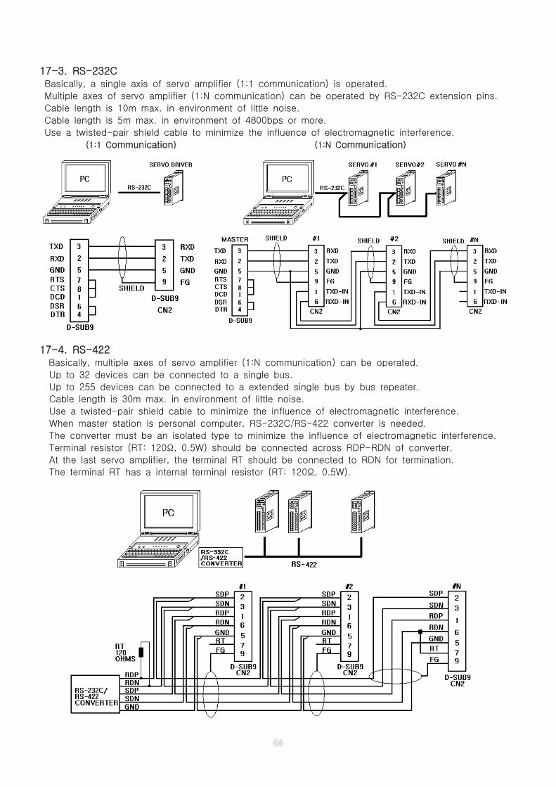
17-3. RS-232CBasically, a single axis of servo amplifier (1:1 communication) is operated.
Multiple axes of servo amplifier (1:N communication) can be operated by RS-232C extension pins.
Cable length is 10m max. in environment of little noise.
Cable length is 5m max. in environment of 4800bps or more.
Use a twisted-pair shield cable to minimize the influence of electromagnetic interference.
(1:1 Communication) (1:N Communication)
17-4. RS-422Basically, multiple axes of servo amplifier (1:N communication) can be operated.
Up to 32 devices can be connected to a single bus.
Up to 255 devices can be connected to a extended single bus by bus repeater.
Cable length is 30m max. in environment of little noise.
Use a twisted-pair shield cable to minimize the influence of electromagnetic interference.
When master station is personal computer, RS-232C/RS-422 converter is needed.
The converter must be an isolated type to minimize the influence of electromagnetic interference.
Terminal resistor (RT: 120 , 0.5W) should be connected across RDP-RDN of converter.Ω
At the last servo amplifier, the terminal RT should be connected to RDN for termination.
The terminal RT has a internal terminal resistor (RT: 120 , 0.5W).Ω
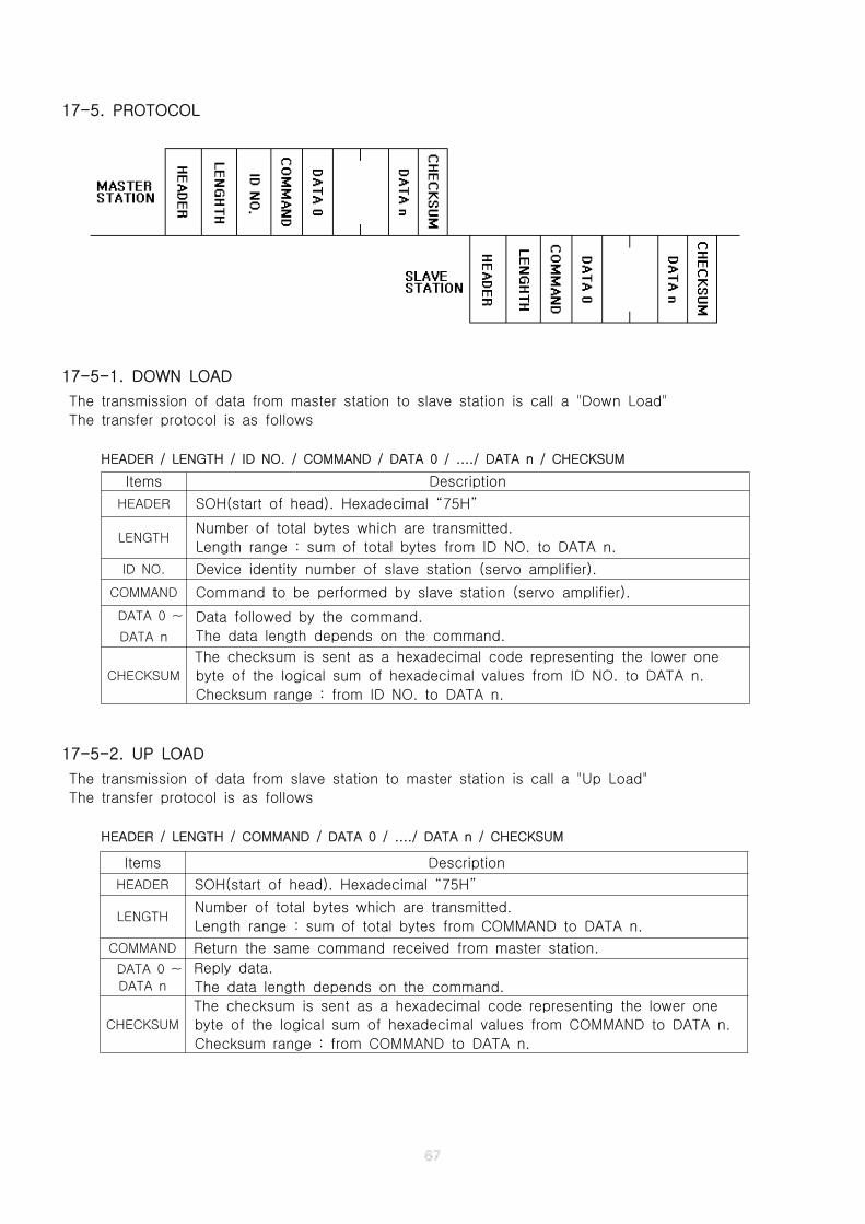
17-5. PROTOCOL
17-5-1. DOWN LOAD
The transmission of data from master station to slave station is call a "Down Load"
The transfer protocol is as follows
HEADER / LENGTH / ID NO. / COMMAND / DATA 0 / ..../ DATA n / CHECKSUM
17-5-2. UP LOAD
The transmission of data from slave station to master station is call a "Up Load"
The transfer protocol is as follows
HEADER / LENGTH / COMMAND / DATA 0 / ..../ DATA n / CHECKSUM
Items Description
HEADER SOH(start of head). Hexadecimal “75H”
LENGTHNumber of total bytes which are transmitted.
Length range : sum of total bytes from ID NO. to DATA n.
ID NO. Device identity number of slave station (servo amplifier).
COMMAND Command to be performed by slave station (servo amplifier).
DATA 0 ~
DATA n
Data followed by the command.
The data length depends on the command.
CHECKSUM
The checksum is sent as a hexadecimal code representing the lower one
byte of the logical sum of hexadecimal values from ID NO. to DATA n.
Checksum range : from ID NO. to DATA n.
Items Description
HEADER SOH(start of head). Hexadecimal “75H”
LENGTHNumber of total bytes which are transmitted.
Length range : sum of total bytes from COMMAND to DATA n.
COMMAND Return the same command received from master station.
DATA 0 ~
DATA n
Reply data.
The data length depends on the command.
CHECKSUM
The checksum is sent as a hexadecimal code representing the lower one
byte of the logical sum of hexadecimal values from COMMAND to DATA n.
Checksum range : from COMMAND to DATA n.
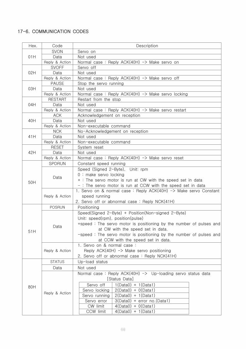
17-6. COMMUNICATION CODES
Hex. Code Description
01H
SVON Servo on
Data Not usedReply & Action Normal case : Reply ACK(40H) -> Make servo on
02H
SVOFF Servo off
Data Not usedReply & Action Normal case : Reply ACK(40H) -> Make servo off
03H
PAUSE Stop the servo running
Data Not usedReply & Action Normal case : Reply ACK(40H) -> Make servo locking
04H
RESTART Restart from the stop
Data Not usedReply & Action Normal case : Reply ACK(40H) -> Make servo restart
40H
ACK Acknowledgement on reception
Data Not usedReply & Action Non-executable command
41H
NCK No-Acknowledgement on reception
Data Not usedReply & Action Non-executable command
42H
RESET System reset
Data Not usedReply & Action Normal case : Reply ACK(40H) -> Make servo reset
50H
SPDRUN Constant speed running
Data
Speed (Signed 2-Byte), Unit: rpm
0 : make servo locking
+ : The servo motor is run at CW with the speed set in data
- : The servo motor is run at CCW with the speed set in data
Reply & Action
1. Servo on & normal case : Reply ACK(40H) -> Make servo Constant
speed running
2. Servo off or abnormal case : Reply NCK(41H)
51H
POSRUN Positioning
Data
Speed(Signed 2-Byte) + Position(Non-signed 2-Byte)
Unit: speed(rpm), position(pulse)
+speed : The servo motor is positioning by the number of pulses and
at CW with the speed set in data.
-speed : The servo motor is positioning by the number of pulses and
at CCW with the speed set in data.
Reply & Action
1. Servo on & normal case :
Reply ACK(40H) -> Make servo positioning
2. Servo off or abnormal case : Reply NCK(41H)
80H
STATUS Up-load status
Data Not used
Reply & Action
Normal case : Reply ACK(40H) -> Up-loading servo status data
[Status Data]
Servo off 1(Data0) + 1(Data1)
Servo locking 2(Data0) + 0(Data1)
Servo running 2(Data0) + 1(Data1)
Servo error 3(Data0) + error no.(Data1)
CW limit 4(Data0) + 0(Data1)
CCW limit 4(Data0) + 1(Data1)
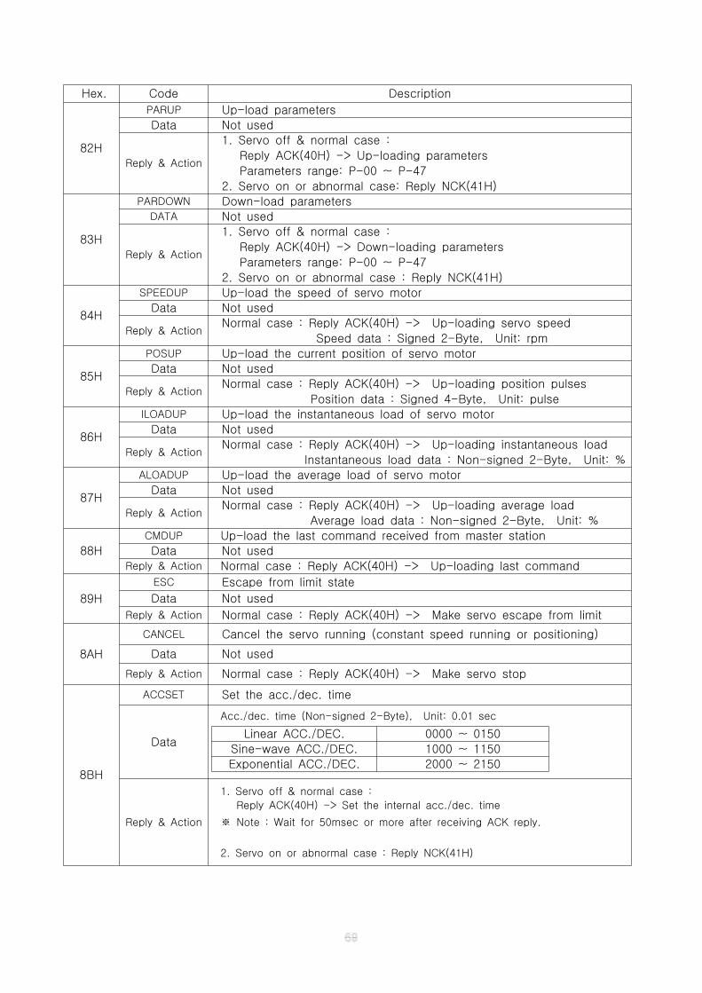
Hex. Code Description
82H
PARUP Up-load parameters
Data Not used
Reply & Action
1. Servo off & normal case :
Reply ACK(40H) -> Up-loading parameters
Parameters range: P-00 ~ P-47
2. Servo on or abnormal case: Reply NCK(41H)
83H
PARDOWN Down-load parametersDATA Not used
Reply & Action
1. Servo off & normal case :
Reply ACK(40H) -> Down-loading parameters
Parameters range: P-00 ~ P-47
2. Servo on or abnormal case : Reply NCK(41H)
84H
SPEEDUP Up-load the speed of servo motor
Data Not used
Reply & ActionNormal case : Reply ACK(40H) -> Up-loading servo speed
Speed data : Signed 2-Byte, Unit: rpm
85H
POSUP Up-load the current position of servo motor
Data Not used
Reply & ActionNormal case : Reply ACK(40H) -> Up-loading position pulses
Position data : Signed 4-Byte, Unit: pulse
86H
ILOADUP Up-load the instantaneous load of servo motor
Data Not used
Reply & ActionNormal case : Reply ACK(40H) -> Up-loading instantaneous load
Instantaneous load data : Non-signed 2-Byte, Unit: %
87H
ALOADUP Up-load the average load of servo motor
Data Not used
Reply & ActionNormal case : Reply ACK(40H) -> Up-loading average load
Average load data : Non-signed 2-Byte, Unit: %
88H
CMDUP Up-load the last command received from master station
Data Not usedReply & Action Normal case : Reply ACK(40H) -> Up-loading last command
89H
ESC Escape from limit state
Data Not used
Reply & Action Normal case : Reply ACK(40H) -> Make servo escape from limit
8AH
CANCEL Cancel the servo running (constant speed running or positioning)
Data Not used
Reply & Action Normal case : Reply ACK(40H) -> Make servo stop
8BH
ACCSET Set the acc./dec. time
Data
Acc./dec. time (Non-signed 2-Byte), Unit: 0.01 sec
Linear ACC./DEC. 0000 ~ 0150
Sine-wave ACC./DEC. 1000 ~ 1150
Exponential ACC./DEC. 2000 ~ 2150
Reply & Action
1. Servo off & normal case :
Reply ACK(40H) -> Set the internal acc./dec. time
Note : Wait for 50msec or more after receiving ACK reply.※
2. Servo on or abnormal case : Reply NCK(41H)

APPENDIX
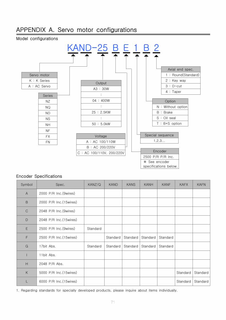
APPENDIX A. Servo motor configurations
Model configurations
KAND-25 B E 1 B 2
Encoder Specifications
Symbol Spec. KANZ/Q KAND KANS KANH KANF KAFX KAFN
A 2000 P/R Inc.(9wires)
B 2000 P/R Inc.(15wires)
C 2048 P/R Inc.(9wires)
D 2048 P/R Inc.(15wires)
E 2500 P/R Inc.(9wires) Standard
F 2500 P/R Inc.(15wires) Standard Standard Standard Standard
G 17bit Abs. Standard Standard Standard Standard Standard
I 11bit Abs.
H 2048 P/R Abs.
K 5000 P/R Inc.(15wires) Standard Standard
L 6000 P/R Inc.(15wires) Standard Standard
1. Regarding standards for specially developed products, please inquire about items individually.
Axial end spec.
1 : Round(Standard)
2 : Key way
3 : D-cut
4 : Taper
Servo motor
K : K Series
A : AC ServoOutput
A3 : 30W
:
04 : 400W
:
25 : 2.5KW
:
50 : 5.0kW
Series
NZ
NQ
ND
NS
NH
NF
FX
FN
Option
N : Without option
B : Brake
S : Oil seal
T : B+S option
Special sequence
1,2,3...
Voltage
A : AC 100/110W
B : AC 200/220V
C : AC 100/110V, 200/220V Encoder
2500 P/R P/R Inc.
See encoder※
specifications below.
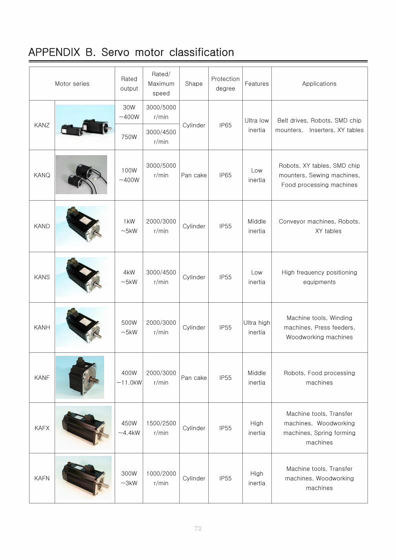
APPENDIX B. Servo motor classification
Motor seriesRated
output
Rated/
Maximum
speed
ShapeProtection
degreeFeatures Applications
KANZ
30W
~400W
3000/5000
r/min
Cylinder IP65Ultra low
inertia
Belt drives, Robots, SMD chip
mounters, Inserters, XY tables750W
3000/4500
r/min
KANQ100W
~400W
3000/5000
r/min Pan cake IP65Low
inertia
Robots, XY tables, SMD chip
mounters, Sewing machines,
Food processing machines
KAND1kW
~5kW
2000/3000
r/minCylinder IP55
Middle
inertia
Conveyor machines, Robots,
XY tables
KANS4kW
~5kW
3000/4500
r/minCylinder IP55
Low
inertia
High frequency positioning
equipments
KANH500W
~5kW
2000/3000
r/minCylinder IP55
Ultra high
inertia
Machine tools, Winding
machines, Press feeders,
Woodworking machines
KANF400W
~11.0kW
2000/3000
r/minPan cake IP55
Middle
inertia
Robots, Food processing
machines
KAFX450W
~4.4kW
1500/2500
r/minCylinder IP55
High
inertia
Machine tools, Transfer
machines, Woodworking
machines, Spring forming
machines
KAFN300W
~3kW
1000/2000
r/minCylinder IP55
High
inertia
Machine tools, Transfer
machines, Woodworking
machines
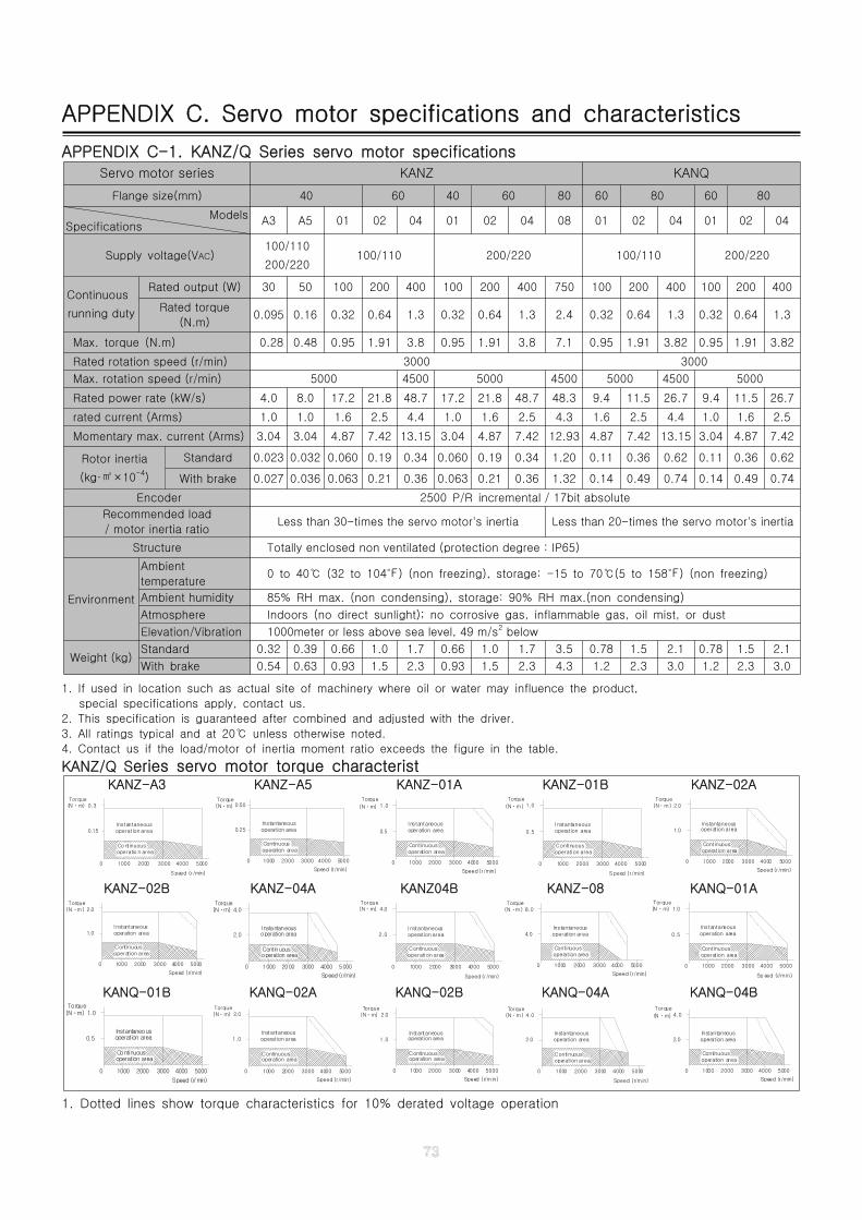
APPENDIX C. Servo motor specifications and characteristics
APPENDIX C-1. KANZ/Q Series servo motor specifications
Servo motor series KANZ KANQ
Flange size(mm) 40 60 40 60 80 60 80 60 80
ModelsSpecifications A3 A5 01 02 04 01 02 04 08 01 02 04 01 02 04
Supply voltage(VAC)100/110
200/220100/110 200/220 100/110 200/220
Continuous
running duty
Rated output (W) 30 50 100 200 400 100 200 400 750 100 200 400 100 200 400
Rated torque
(N.m)0.095 0.16 0.32 0.64 1.3 0.32 0.64 1.3 2.4 0.32 0.64 1.3 0.32 0.64 1.3
Max. torque (N.m) 0.28 0.48 0.95 1.91 3.8 0.95 1.91 3.8 7.1 0.95 1.91 3.82 0.95 1.91 3.82
Rated rotation speed (r/min) 3000 3000
Max. rotation speed (r/min) 5000 4500 5000 4500 5000 4500 5000
Rated power rate (kW/s) 4.0 8.0 17.2 21.8 48.7 17.2 21.8 48.7 48.3 9.4 11.5 26.7 9.4 11.5 26.7
rated current (Arms) 1.0 1.0 1.6 2.5 4.4 1.0 1.6 2.5 4.3 1.6 2.5 4.4 1.0 1.6 2.5
Momentary max. current (Arms) 3.04 3.04 4.87 7.42 13.15 3.04 4.87 7.42 12.93 4.87 7.42 13.15 3.04 4.87 7.42
Rotor inertia
(kg· ×10㎡ -4)
Standard 0.023 0.032 0.060 0.19 0.34 0.060 0.19 0.34 1.20 0.11 0.36 0.62 0.11 0.36 0.62
With brake 0.027 0.036 0.063 0.21 0.36 0.063 0.21 0.36 1.32 0.14 0.49 0.74 0.14 0.49 0.74
Encoder 2500 P/R incremental / 17bit absolute
Recommended load
/ motor inertia ratioLess than 30-times the servo motor's inertia Less than 20-times the servo motor's inertia
Structure Totally enclosed non ventilated (protection degree : IP65)
Environment
Ambient
temperature0 to 40 (32 to 104 ) (non freezing), storage: -15 to 70 (5 to 158 ) (non freezing)℃ ℉ ℃ ℉
Ambient humidity 85% RH max. (non condensing), storage: 90% RH max.(non condensing)
Atmosphere Indoors (no direct sunlight); no corrosive gas, inflammable gas, oil mist, or dust
Elevation/Vibration 1000meter or less above sea level, 49 m/s2 below
Weight (kg)Standard 0.32 0.39 0.66 1.0 1.7 0.66 1.0 1.7 3.5 0.78 1.5 2.1 0.78 1.5 2.1
With brake 0.54 0.63 0.93 1.5 2.3 0.93 1.5 2.3 4.3 1.2 2.3 3.0 1.2 2.3 3.0
1. If used in location such as actual site of machinery where oil or water may influence the product,
special specifications apply, contact us.
2. This specification is guaranteed after combined and adjusted with the driver.
3. All ratings typical and at 20 unless otherwise noted.℃
4. Contact us if the load/motor of inertia moment ratio exceeds the figure in the table.
KANZ/Q Series servo motor torque characteristKANZ-A3 KANZ-A5 KANZ-01A KANZ-01B KANZ-02A
Speed (r/min)
0 1000 2000 3000 4000
(Nㆍm)Torque
0.15
0.3
5000
Instantaneousoperation area
Co ntinuousoperatio n area
5000
Instantaneous0.25 operation area
operation area
2000
Speed (r/min)
Continuous
0 1000 3000 4000
0.50Torque(Nㆍm) 1.0
0.5
(Nㆍm)
Torque
Continuous
operation area
1000
operation area
Instantaneous
0 2000 3000 50004000
Speed (r/min)
Instantaneous
0
0.5
operati on area
2000
S peed (r/min)
1000 3000
operation area
Conti nuous
Torque
(Nㆍm) 1.0
50004000 3000
Instantaneousoperation area
Continuousoperation area
1000 2000
Speed (r/min)
50004000
Torque(Nㆍm)
0
1.0
2.0
KANZ-02B KANZ-04A KANZ04B KANZ-08 KANQ-01A
1.0
(Nㆍm)Torque
2.0
50003000 400020000 1000
Speed (r/min)
operation areaContinuous
operation areaInstantaneous
3000
operation areaContinuous
operation areaInstantaneous
10000
2.0
4.0
2000
Speed (r/min)
50004000
(Nㆍm)Torque
Instantaneous
Speed (r/min)
operation area
Continuousoperati on area
10000
2.0
2000 3000 50004000
4.0(Nㆍm)Torque
10000 2000 3000
Instantaneousoperation area
Conti nuousoperation area
4.0
8.0Torque
(Nㆍm)
4000 5000
Speed (r/min)
Continuousoperation area
2000
Sp eed (r/m in)
3000 4000 5000
(Nㆍm)Torque
Instantaneous
0.5
0
operation area
1000
1.0
KANQ-01B KANQ-02A KANQ-02B KANQ-04A KANQ-04B
0.5
Torque(Nㆍm) 1.0
Instantaneous
operation area
1000
Speed (r/min)
0 2000
Continuous
operation area
40003000 5000 20000 1000
(Nㆍm)Torque
2.0
1.0 operation area
operation areaContinuous
Instantaneous
50003000 4000
Speed (r/min)
Instantaneous1.0
Speed (r/m in)
Continuous
1000
operation area
0 2000
operation area
40003000 5000
Torque(Nㆍm) 2.0
40003000 5000
Speed (r/min)
10000 2000
Torque(Nㆍm)
Instantaneousoperation area
Conti nuousoperat ion area
2.0
4.0
2.0
(Nㆍm)
Torque4.0
50003000 400020000 1000
Speed (r/min)
operation areaContinuous
operation areaInstantaneous
1. Dotted lines show torque characteristics for 10% derated voltage operation
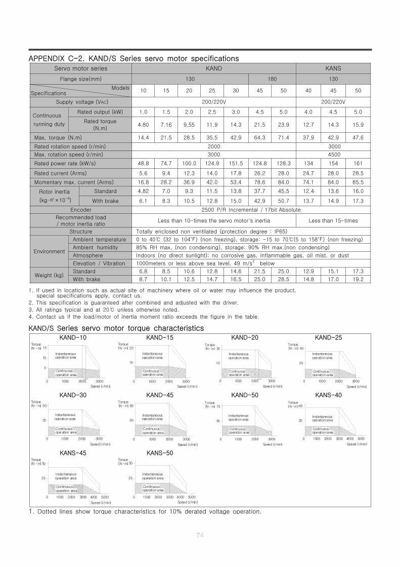
APPENDIX C-2. KAND/S Series servo motor specifications
1. If used in location such as actual site of machinery where oil or water may influence the product,special specifications apply, contact us.
2. This specification is guaranteed after combined and adjusted with the driver.
3. All ratings typical and at 20 unless otherwise noted.℃
4. Contact us if the load/motor of inertia moment ratio exceeds the figure in the table.
KAND/S Series servo motor torque characteristicsKAND-10 KAND-15 KAND-20 KAND-25
Speed (r/min)
300010000 2000
operation areaInstantaneous
operation areaContinuous
5
15Torque(Nㆍm)
10
(2200)
(Nㆍm)Torque
1000
Continuousoperation area
0 2000
Speed (r/min)
3000
operation areaInstantaneous
10
20
Speed (r/min)
300010000 2000
operation areaInstantaneous
operation areaContinuous
15
30Torque(Nㆍm)
(2200)
Speed (r/min)
30001000 2000
operation areaInstantaneous
operation areaContinuous
Torque(Nㆍm)
0
20
40
KAND-30 KAND-45 KAND-50 KANS-40
25
operation areaContinuous
0 1000
Speed (r/min)
2000 3000
Torque(Nㆍm)
operation areaInstantaneous
50
30
3000
Speed (r/min)
1000
Continuousoperation area
0 2000
operation areaInstantaneous
60(Nㆍm)Torque
Speed (r/min)
3000
35
operation areaContinuous
0 1000 2000
Instantaneousoperation area
Torque(Nㆍm) 70
Speed (r/min)
4000
Instantaneous
operation areaContinuous
operation area
10000
20
30002000
40(Nㆍm)Torque
5000
KANS-45 KANS-50
(Nㆍm)Torque
1000
Continuousoperation area
0 2000 4000
Speed (r/min)
3000 5000
operation areaInstantaneous
25
50
5000
Speed (r/min)
operation areaContinuous
0 1000 30002000 4000
Instantaneousoperation area
Torque
25
(Nㆍm) 50
1. Dotted lines show torque characteristics for 10% derated voltage operation.
Servo motor series KAND KANS
Flange size(mm) 130 180 130
ModelsSpecifications 10 15 20 25 30 45 50 40 45 50
Supply voltage (VAC) 200/220V 200/220V
Continuous
running duty
Rated output (kW) 1.0 1.5 2.0 2.5 3.0 4.5 5.0 4.0 4.5 5.0
Rated torque
(N.m)4.80 7.16 9.55 11.9 14.3 21.5 23.9 12.7 14.3 15.9
Max. torque (N.m) 14.4 21.5 28.5 35.5 42.9 64.3 71.4 37.9 42.9 47.6
Rated rotation speed (r/min) 2000 3000
Max. rotation speed (r/min) 3000 4500
Rated power rate (kW/s) 48.8 74.7 100.0 124.9 151.5 124.8 128.3 134 154 161
Rated current (Arms) 5.6 9.4 12.3 14.0 17.8 26.2 28.0 24.7 28.0 28.5
Momentary max. current (Arms) 16.8 28.2 36.9 42.0 53.4 78.6 84.0 74.1 84.0 85.5
Rotor inertia
(kg· ×10㎡ -4)
Standard 4.82 7.0 9.3 11.5 13.8 37.7 45.5 12.4 13.6 16.0
With brake 6.1 8.3 10.5 12.8 15.0 42.9 50.7 13.7 14.9 17.3
Encoder 2500 P/R Incremental / 17bit Absolute
Recommended load/ motor inertia ratio
Less than 10-times the servo motor's inertia Less than 15-times
Structure Totally enclosed non ventilated (protection degree : IP65)
Environment
Ambient temperature 0 to 40 (32 to 104 ) (non freezing), storage: -15 to 70 (5 to 158 ) (non freezing)℃ ℉ ℃ ℉
Ambient humidity 85% RH max. (non condensing), storage: 90% RH max.(non condensing)
Atmosphere Indoors (no direct sunlight); no corrosive gas, inflammable gas, oil mist, or dust
Elevation / Vibration 1000meters or less above sea level, 49 m/s2 below
Weight (kg)Standard 6.8 8.5 10.6 12.8 14.6 21.5 25.0 12.9 15.1 17.3
With brake 8.7 10.1 12.5 14.7 16.5 25.0 28.5 14.8 17.0 19.2
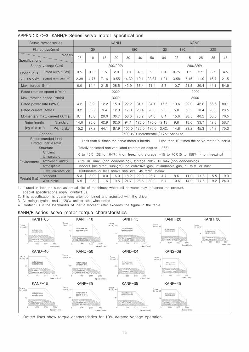
APPENDIX C-3. KANH/F Series servo motor specifications
Servo motor series KANH KANF
Flange size(mm) 130 180 130 180 220
Models
Specifications05 10 15 20 30 40 50 04 08 15 25 35 45
Supply voltage (VAC) 200/220V 200/220V
Continuous
running duty
Rated output (kW) 0.5 1.0 1.5 2.0 3.0 4.0 5.0 0.4 0.75 1.5 2.5 3.5 4.5
Rated torque(N.m) 2.39 4.77 7.16 9.55 14.32 19.1 23.87 1.91 3.58 7.16 11.9 16.7 21.5
Max. torque (N.m) 6.0 14.4 21.5 28.5 42.9 56.4 71.4 5.3 10.7 21.5 30.4 44.1 54.9
Rated rotation speed (r/min) 2000 2000
Max. rotation speed (r/min) 3000 3000
Rated power rate (kW/s) 4.2 8.9 12.2 15.0 22.2 31.1 34.1 17.5 13.6 29.0 42.6 66.5 80.1
Rated current (Arms) 3.2 5.6 9.4 12.3 17.8 23.4 28.0 2.8 5.0 9.5 13.4 20.0 23.5
Momentary max. current (Arms) 8.1 16.8 28.0 36.7 53.6 70.2 84.0 8.4 15.0 28.5 40.2 60.0 70.5
Rotor inertia
(kg· ×10㎡ -4)
Standard 14.0 26.0 42.9 62.0 94.1 120.0 170.0 2.13 9.6 18.0 33.7 42.6 58.7
With brake 15.2 27.2 44.1 67.9 100.0 126.0 176.0 3.42. 14.8 23.2 45.3 54.3 70.3
Encoder 2500 P/R Incremental / 17bit Absolute
Recommended load
/ motor inertia ratioLess than 5-times the servo motor's inertia Less than 10-times the servo motor 's inertia
Structure Totally enclosed non ventilated (protection degree : IP65)
Environment
Ambient
temperature0 to 40 (32 to 104 ) (non freezing), storage: -15 to 70 (5 to 158 ) (non freezing)℃ ℉ ℃ ℉
Ambient humidity 85% RH max. (non condensing), storage: 90% RH max.(non condensing)
Atmosphere Indoors (no direct sunlight); no corrosive gas, inflammable gas, oil mist, or dust
Elevation/Vibration 1000meters or less above sea level, 49 m/s2 below
Weight (kg)Standard 5.3 8.9 10.0 16.0 18.2 22.0 26.7 4.7 8.6 11.0 14.8 15.5 19.9
With brake 6.9 9.5 11.6 19.5 21.7 25.5 30.2 6.7 10.6 14.0 17.5 19.2 24.3
1. If used in location such as actual site of machinery where oil or water may influence the product,
special specifications apply, contact us.
2. This specification is guaranteed after combined and adjusted with the driver.
3. All ratings typical and at 20 unless otherwise noted.℃
4. Contact us if the load/motor of inertia moment ratio exceeds the figure in the table.
KANH/F series servo motor torque characteristics
KANH-05 KANH-10 KANH-15 KANH-20 KANH-30
2.5
operati on areaContinuous
0 1000
Speed (r/m in)
2000 3000
Torque
(Nㆍm)
operati on areaInstantaneous
5.0(Nㆍm)Torque
0 1000
Speed (r/min)
(2200)
2000 3000
Instantaneous
Continuousoperation area
operation area
5
10
15
Speed (r/min)
300010000 2000
operation areaInstantaneous
operation areaContinuous
10
20Torque(Nㆍm)
3000
Speed (r/min)
0 1000(2200)
2000
Continuousoperation area
Instantaneousoperation area
15
(Nㆍm)Torque
30
25
3000
Speed (r/min)
1000
Continuousoperation area
0 2000
operation areaInstantaneous
50(Nㆍm)Torque
KAND-40 KAND-50 KAND-04 KANS-08Torque
3000
Speed (r/min)
Continuous
operation areaInstantaneous
1000
operation area
0
50
25
(Nㆍm)
2000 3000
Speed (r/min)
Torque
operation areaInstantaneous
Continuousoperation area
0
(Nㆍm)
35
70
1000 2000
Torque
(Nㆍm)
operation area
operation area
0 1000
Continuous
2.5
Speed (r/ min)
2000 3000
Instantaneous
5.0
3000200010000
S peed (r/min)
Torque
(Nㆍm)
operation areaInstantaneous
operation areaContinuous
5
10
KANF-15 KANF-25 KANF-35 KANF-45
3000
Speed (r/min)
operation area
operation areaContinuous
0
10
20001000
Instantaneous
Torque(Nㆍm) 20
15
operation areaContinuous
0 1000
Speed (r/min)
2000 3000
Torque(Nㆍm)
operation areaInstantaneous
30Torque(Nㆍm)
25
operation area
0 1000
Continuous
Speed (r/min)
2000 3000
operation areaInstantaneous
50
3000
Speed (r/min)
25
Continuous
1000
operation area
0 2000
Instantaneousoperation area
50(Nㆍm)Torque
1. Dotted lines show torque characteristics for 10% derated voltage operation.
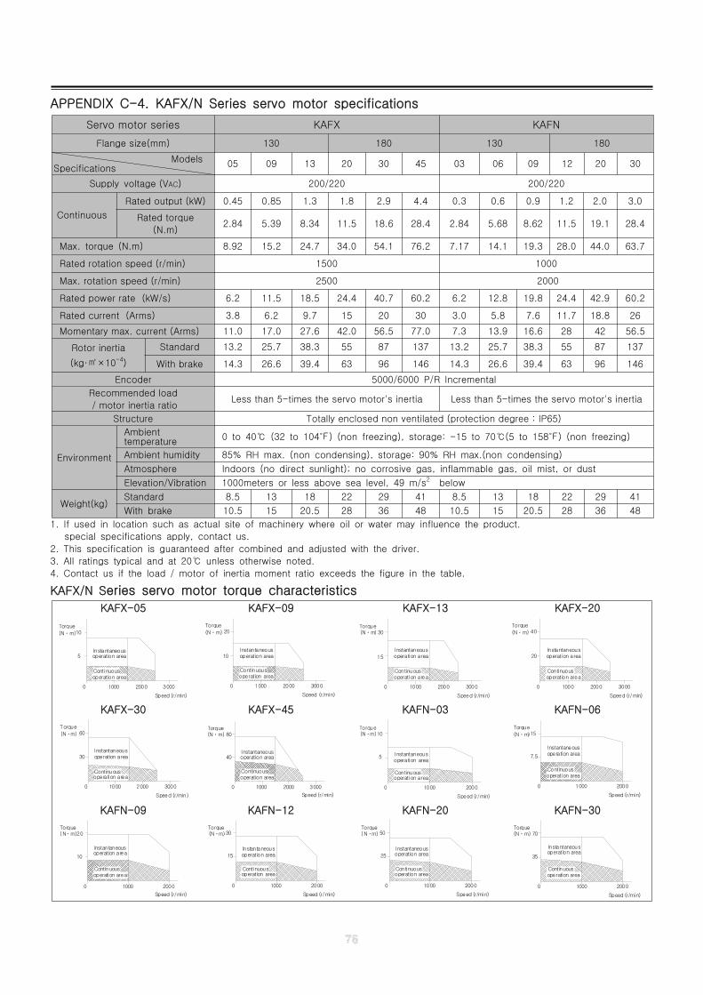
APPENDIX C-4. KAFX/N Series servo motor specifications
1. If used in location such as actual site of machinery where oil or water may influence the product.
special specifications apply, contact us.
2. This specification is guaranteed after combined and adjusted with the driver.
3. All ratings typical and at 20 unless otherwise noted.℃
4. Contact us if the load / motor of inertia moment ratio exceeds the figure in the table.
KAFX/N Series servo motor torque characteristics
KAFX-05 KAFX-09 KAFX-13 KAFX-20
Continuous
operation areaInstantaneous
operation area
5
0
Torque
(Nㆍm)10
1000
Speed (r/min)
2000 3000
operation area
Instantaneousoperation area10
0
(Nㆍm)
Torque20
Continuous
1000
Speed (r/min)
2000 3000 1000
Continuous
operation areaInstantaneous
operation area
0
15
Torque(Nㆍm) 30
2000 3000
Speed (r/min)
operation area
Instantaneousoperation area20
0
(Nㆍm)
Torque40
Continuous
1000
Speed (r/min)
2000 3000
KAFX-30 KAFX-45 KAFN-03 KAFN-06
operation areaInstantaneous
operation area
0
Torque
(Nㆍm)
30
60
Continuous
1000
Speed (r/min)
2000 3000 1000
Continuousoperation area
Instantaneousoperation area
0
(Nㆍm)Torque
40
80
2000 3000
Speed (r/min)
operation area
Instantaneousoperation area
5
0
(Nㆍm)Torque
10
Continuous
1000
Speed (r/min)
2000
Instantaneousoperation area
operation area
7.5
0
Torque
(Nㆍm)15
Continuous
Speed (r/min)
1000 2000
KAFN-09 KAFN-12 KAFN-20 KAFN-30
Continuousoperation area
Instantaneousoperation area
0
10
(Nㆍm)Torque
20
1000 2000
Speed (r/min)
Instantaneousoperation area
operation area
15
0
Torque(Nㆍm)30
Continuous
Speed (r/min)
1000 2000
operation area
operation areaInstantaneous
25
0
(Nㆍm)Torque
50
Continuous
Speed (r/min)
1000 2000
operation areaInstantaneous
operation area
35
0
(Nㆍm)Torque
70
Continuous
Speed (r/min)
1000 2000
Servo motor series KAFX KAFN
Flange size(mm) 130 180 130 180
ModelsSpecifications 05 09 13 20 30 45 03 06 09 12 20 30
Supply voltage (VAC) 200/220 200/220
Continuous
Rated output (kW) 0.45 0.85 1.3 1.8 2.9 4.4 0.3 0.6 0.9 1.2 2.0 3.0
Rated torque
(N.m)2.84 5.39 8.34 11.5 18.6 28.4 2.84 5.68 8.62 11.5 19.1 28.4
Max. torque (N.m) 8.92 15.2 24.7 34.0 54.1 76.2 7.17 14.1 19.3 28.0 44.0 63.7
Rated rotation speed (r/min) 1500 1000
Max. rotation speed (r/min) 2500 2000
Rated power rate (kW/s) 6.2 11.5 18.5 24.4 40.7 60.2 6.2 12.8 19.8 24.4 42.9 60.2
Rated current (Arms) 3.8 6.2 9.7 15 20 30 3.0 5.8 7.6 11.7 18.8 26
Momentary max. current (Arms) 11.0 17.0 27.6 42.0 56.5 77.0 7.3 13.9 16.6 28 42 56.5
Rotor inertia
(kg· ×10㎡ -4)
Standard 13.2 25.7 38.3 55 87 137 13.2 25.7 38.3 55 87 137
With brake 14.3 26.6 39.4 63 96 146 14.3 26.6 39.4 63 96 146
Encoder 5000/6000 P/R Incremental
Recommended load
/ motor inertia ratioLess than 5-times the servo motor's inertia Less than 5-times the servo motor's inertia
Structure Totally enclosed non ventilated (protection degree : IP65)
Environment
Ambienttemperature 0 to 40 (32 to 104 ) (non freezing), storage: -15 to 70 (5 to 158 ) (non freezing)℃ ℉ ℃ ℉
Ambient humidity 85% RH max. (non condensing), storage: 90% RH max.(non condensing)
Atmosphere Indoors (no direct sunlight); no corrosive gas, inflammable gas, oil mist, or dust
Elevation/Vibration 1000meters or less above sea level, 49 m/s2 below
Weight(kg)Standard 8.5 13 18 22 29 41 8.5 13 18 22 29 41
With brake 10.5 15 20.5 28 36 48 10.5 15 20.5 28 36 48
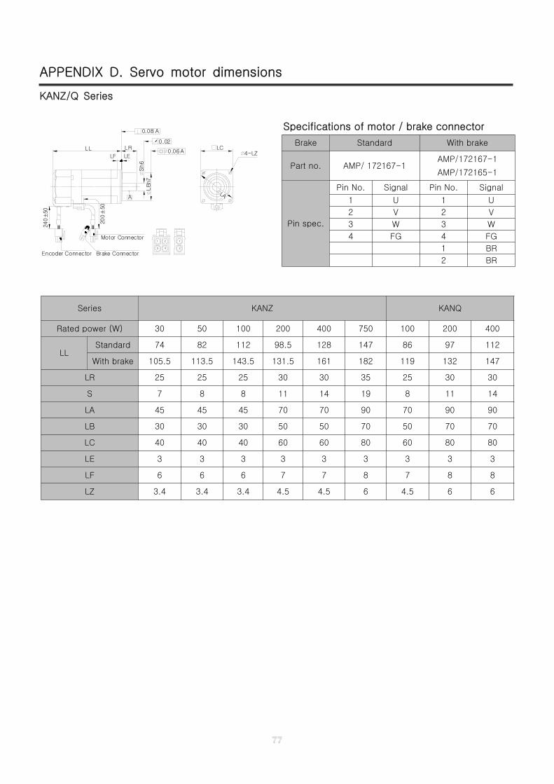
APPENDIX D. Servo motor dimensions
KANZ/Q Series
Specifications of motor / brake connector
Brake Standard With brake
Part no. AMP/ 172167-1AMP/172167-1
AMP/172165-1
Pin spec.
Pin No. Signal Pin No. Signal
1 U 1 U
2 V 2 V
3 W 3 W
4 FG 4 FG
1 BR
2 BR
3 4 2
1 2 1Motor Connector
Brake ConnectorEncoder Connector
LR
240±
50
200±
50
LL
LELF
A
0.08 A
0.02
ALC
LBh7
Sh6
0.06 4-LZ
LA
Series KANZ KANQ
Rated power (W) 30 50 100 200 400 750 100 200 400
LLStandard 74 82 112 98.5 128 147 86 97 112
With brake 105.5 113.5 143.5 131.5 161 182 119 132 147
LR 25 25 25 30 30 35 25 30 30
S 7 8 8 11 14 19 8 11 14
LA 45 45 45 70 70 90 70 90 90
LB 30 30 30 50 50 70 50 70 70
LC 40 40 40 60 60 80 60 80 80
LE 3 3 3 3 3 3 3 3 3
LF 6 6 6 7 7 8 7 8 8
LZ 3.4 3.4 3.4 4.5 4.5 6 4.5 6 6
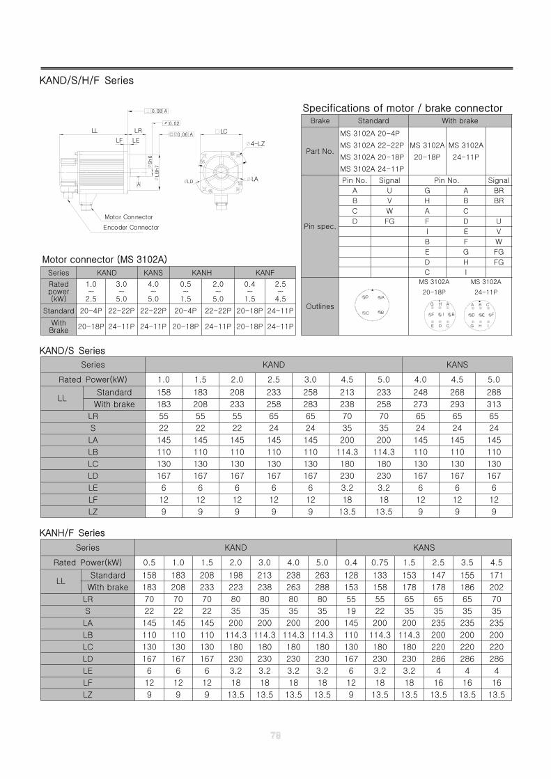
KAND/S/H/F Series
KAND/S Series
KANH/F Series
LRLL
LELF
Encoder Connector
0.08 A
0.02
A
A
Motor Connector
LC
LB
h7
Sh
6
LD
4-LZ
LA
0.06
Specifications of motor / brake connectorBrake Standard With brake
Part No.
MS 3102A 20-4P
MS 3102A 22-22P
MS 3102A 20-18P
MS 3102A 24-11P
MS 3102A
20-18P
MS 3102A
24-11P
Pin spec.
Pin No. Signal Pin No. Signal
A U G A BR
B V H B BR
C W A C
D FG F D U
I E V
B F W
E G FG
D H FG
C I
Outlines
D A
BC
MS 3102A
20-18P
MS 3102A
24-11P
HG
D
A B
I
E F
C
DE
F
G H
C
I B
A
Motor connector (MS 3102A)
Series KAND KANS KANH KANF
Ratedpower(kW)
1.0~
2.5
3.0~
5.0
4.0~
5.0
0.5~
1.5
2.0~
5.0
0.4~
1.5
2.5~
4.5
Standard 20-4P 22-22P 22-22P 20-4P 22-22P 20-18P 24-11P
WithBrake 20-18P 24-11P 24-11P 20-18P 24-11P 20-18P 24-11P
Series KAND KANS
Rated Power(kW) 1.0 1.5 2.0 2.5 3.0 4.5 5.0 4.0 4.5 5.0
LLStandard 158 183 208 233 258 213 233 248 268 288
With brake 183 208 233 258 283 238 258 273 293 313
LR 55 55 55 65 65 70 70 65 65 65
S 22 22 22 24 24 35 35 24 24 24
LA 145 145 145 145 145 200 200 145 145 145
LB 110 110 110 110 110 114.3 114.3 110 110 110
LC 130 130 130 130 130 180 180 130 130 130
LD 167 167 167 167 167 230 230 167 167 167
LE 6 6 6 6 6 3.2 3.2 6 6 6
LF 12 12 12 12 12 18 18 12 12 12
LZ 9 9 9 9 9 13.5 13.5 9 9 9
Series KAND KANS
Rated Power(kW) 0.5 1.0 1.5 2.0 3.0 4.0 5.0 0.4 0.75 1.5 2.5 3.5 4.5
LLStandard 158 183 208 198 213 238 263 128 133 153 147 155 171
With brake 183 208 233 223 238 263 288 153 158 178 178 186 202
LR 70 70 70 80 80 80 80 55 55 65 65 65 70
S 22 22 22 35 35 35 35 19 22 35 35 35 35
LA 145 145 145 200 200 200 200 145 200 200 235 235 235
LB 110 110 110 114.3 114.3 114.3 114.3 110 114.3 114.3 200 200 200
LC 130 130 130 180 180 180 180 130 180 180 220 220 220
LD 167 167 167 230 230 230 230 167 230 230 286 286 286
LE 6 6 6 3.2 3.2 3.2 3.2 6 3.2 3.2 4 4 4
LF 12 12 12 18 18 18 18 12 18 18 16 16 16
LZ 9 9 9 13.5 13.5 13.5 13.5 9 13.5 13.5 13.5 13.5 13.5
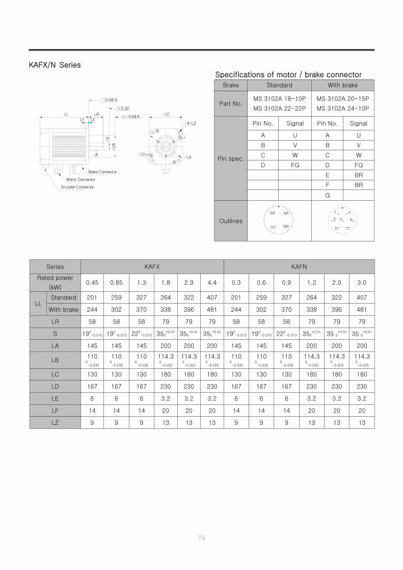
KAFX/N Series
Specifications of motor / brake connector
Brake Standard With brake
Part No.MS 3102A 18-10P
MS 3102A 22-22P
MS 3102A 20-15P
MS 3102A 24-10P
Pin spec.
Pin No. Signal Pin No. Signal
A U A U
B V B V
C W C W
D FG D FG
E BR
F BR
G
Outlines
D A
BC D
A
C
BE
F
G
LR LCLL
LELF
Encoder Connector
Motor Connector
Brake Connector
A
0.04 A
0.02
ALB
S
4-LZ
LDLA
0.04
Series KAFX KAFN
Rated power
(kW)0.45 0.85 1.3 1.8 2.9 4.4 0.3 0.6 0.9 1.2 2.0 3.0
LLStandard 201 259 327 264 322 407 201 259 327 264 322 407
With brake 244 302 370 338 396 481 244 302 370 338 396 481
LR 58 58 58 79 79 79 58 58 58 79 79 79
S 190-0.013 190
-0.013 220-0.013 350
+0.01 350+0.01 350
+0.01 190-0.013 190
-0.013 220-0.013 350
+0.01 35 0+0.01 35 0
+0.01
LA 145 145 145 200 200 200 145 145 145 200 200 200
LB110
0-0.035
1100-0.035
1100-0.035
114.30-0.025
114.30-0.025
114.30-0.025
1100-0.035
1100-0.035
1100-0.035
114.30-0.025
114.30-0.025
114.30-0.025
LC 130 130 130 180 180 180 130 130 130 180 180 180
LD 167 167 167 230 230 230 167 167 167 230 230 230
LE 6 6 6 3.2 3.2 3.2 6 6 6 3.2 3.2 3.2
LF 14 14 14 20 20 20 14 14 14 20 20 20
LZ 9 9 9 13 13 13 9 9 9 13 13 13
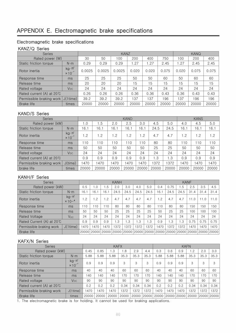
APPENDIX E. Electromagnetic brake specifications
Electromagnetic brake specifications
1. The electromagnetic brake is for holding. It cannot be used for braking applications.
KANZ/Q SeriesSeries KANZ KANQ
Rated power (W) 30 50 100 200 400 750 100 200 400
Static friction torque N·m 0.29 0.29 0.29 1.27 1.27 2.45 1.27 2.45 2.45
Rotor inertiakg·㎡×10-⁴ 0.0025 0.0025 0.0025 0.020 0.020 0.075 0.020 0.075 0.075
Response time ms 25 25 25 50 50 60 50 60 60
Release time ms 20 20 20 15 15 15 15 15 15
Rated voltage VDC 24 24 24 24 24 24 24 24 24
Rated current (A) at 20℃ 0.26 0.26 0.26 0.36 0.36 0.43 0.36 0.43 0.43
Permissible braking work J(1time) 39.2 39.2 39.2 137 137 196 137 196 196
Brake life times 20000 20000 20000 20000 20000 20000 20000 20000 20000
KAND/S SeriesSeries KAND KANS
Rated power (kW) 1.0 1.5 2.0 2.5 3.0 4.5 5.0 4.0 4.5 5.0
Static friction torque N·m 16.1 16.1 16.1 16.1 16.1 24.5 24.5 16.1 16.1 16.1
Rotor inertiakg·㎡
×10-⁴ 1.2 1.2 1.2 1.2 1.2 4.7 4.7 1.2 1.2 1.2
Response time ms 110 110 110 110 110 80 80 110 110 110
Release time ms 50 50 50 50 50 25 25 50 50 50
Rated voltage VDC 24 24 24 24 24 24 24 24 24 24
Rated current (A) at 20℃ 0.9 0.9 0.9 0.9 0.9 1.3 1.3 0.9 0.9 0.9
Permissible braking work J(time) 1470 1470 1470 1470 1470 1372 1372 1470 1470 1470
brake life times 20000 20000 20000 20000 20000 20000 20000 20000 20000 20000
KANH/F SeriesSeries KANH KANF
Rated power (kW) 0.5 1.0 1.5 2.0 3.0 4.0 5.0 0.4 0.75 1.5 2.5 3.5 4.5
Static friction torque N·m 16.1 16.1 16.1 24.5 24.5 24.5 24.5 16.1 24.5 24.5 31.4 31.4 31.4
Rotor inertiakg·㎡
×10-⁴1.2 1.2 1.2 4.7 4.7 4.7 4.7 1.2 4.7 4.7 11.0 11.0 11.0
Response time ms 110 110 110 80 80 80 80 110 80 80 150 150 150
Release time ms 50 50 50 25 25 25 25 50 25 25 100 100 100
Rated Voltage VDC 24 24 24 24 24 24 24 24 24 24 24 24 24
Rated Current (A) at 20℃ 0.9 0.9 0.9 1.3 1.3 1.3 1.3 0.9 1.3 1.3 0.75 0.75 0.75
Permissible braking work J(1time) 1470 1470 1470 1372 1372 1372 1372 1470 1372 1372 1470 1470 1470
Brake life 20000 20000 20000 20000 20000 20000 20000 20000 20000 20000 20000 20000 20000
KAFX/N SeriesSeries KAFX KAFN
Rated power (kW) 0.45 0.85 1.3 1.8 2.9 4.4 0.3 0.6 0.9 1.2 2.0 3.0
Static friction torque N·m 5.88 5.88 5.88 35.3 35.3 35.3 5.88 5.88 5.88 35.3 35.3 35.3
Rotor inertiakg·㎡
×10-⁴ 0.9 0.9 0.9 3 3 3 0.9 0.9 0.9 3 3 3
Response time ms 40 40 40 60 60 60 40 40 40 60 60 60
Release time ms 140 140 140 170 170 170 140 140 140 170 170 170
Rated voltage VDC 90 90 90 90 90 90 90 90 90 90 90 90
Rated current (A) at 20℃ 0.2 0.2 0.2 0.34 0.34 0.34 0.2 0.2 0.2 0.34 0.34 0.34
Permissible braking work J(1time) 1470 1470 1470 1372 1372 1372 1470 1470 1470 1372 1372 1372
Brake life times 20000 20000 20000 20000 20000 20000 20000 20000 20000 20000 20000 20000
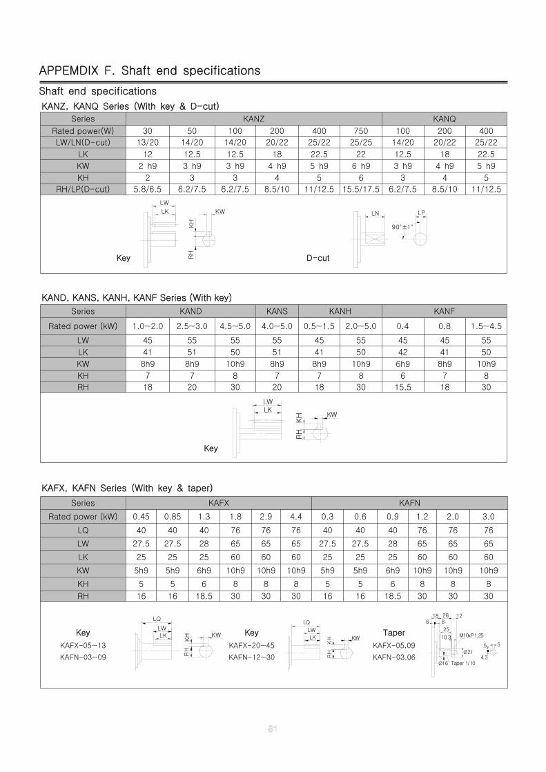
APPEMDIX F. Shaft end specifications
Shaft end specifications
KANZ, KANQ Series (With key & D-cut)
Series KANZ KANQ
Rated power(W) 30 50 100 200 400 750 100 200 400
LW/LN(D-cut) 13/20 14/20 14/20 20/22 25/22 25/25 14/20 20/22 25/22
LK 12 12.5 12.5 18 22.5 22 12.5 18 22.5
KW 2 h9 3 h9 3 h9 4 h9 5 h9 6 h9 3 h9 4 h9 5 h9
KH 2 3 3 4 5 6 3 4 5
RH/LP(D-cut) 5.8/6.5 6.2/7.5 6.2/7.5 8.5/10 11/12.5 15.5/17.5 6.2/7.5 8.5/10 11/12.5
Key
LW
RH
KH
LK KW
D-cut
LN LP
90°±1°
KAND, KANS, KANH, KANF Series (With key)
Series KAND KANS KANH KANF
Rated power (kW) 1.0~2.0 2.5~3.0 4.5~5.0 4.0~5.0 0.5~1.5 2.0~5.0 0.4 0.8 1.5~4.5
LW 45 55 55 55 45 55 45 45 55
LK 41 51 50 51 41 50 42 41 50
KW 8h9 8h9 10h9 8h9 8h9 10h9 6h9 8h9 10h9
KH 7 7 8 7 7 8 6 7 8
RH 18 20 30 20 18 30 15.5 18 30
Key
LWLK
KW
RH
KH
KAFX, KAFN Series (With key & taper)
Series KAFX KAFN
Rated power (kW) 0.45 0.85 1.3 1.8 2.9 4.4 0.3 0.6 0.9 1.2 2.0 3.0
LQ 40 40 40 76 76 76 40 40 40 76 76 76
LW 27.5 27.5 28 65 65 65 27.5 27.5 28 65 65 65
LK 25 25 25 60 60 60 25 25 25 60 60 60
KW 5h9 5h9 6h9 10h9 10h9 10h9 5h9 5h9 6h9 10h9 10h9 10h9
KH 5 5 6 8 8 8 5 5 6 8 8 8
RH 16 16 18.5 30 30 30 16 16 18.5 30 30 30
Key
KAFX-05~13
KAFN-03~09
KW
RH
KH
LWLK
LQ
Key
KAFX-20~45
KAFN-12~30
LW
LK
LQ
KW
RH
KH
Taper
KAFX-05,09
KAFN-03,06
M10xP1.25
Ø21
10.3
122818
Ø16 Taper 1/104.3
5 5
6 8
25
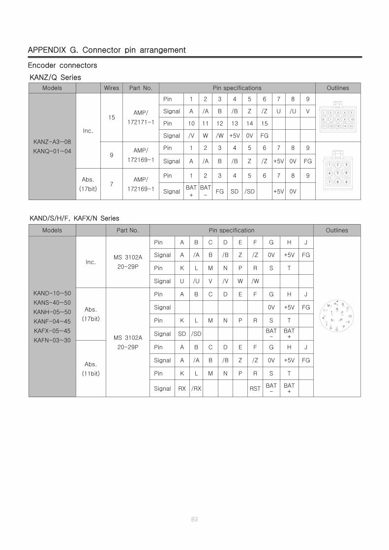
APPENDIX G. Connector pin arrangement
Encoder connectors
KANZ/Q Series
Models Wires Part No. Pin specifications Outlines
KANZ-A3~08
KANQ-01~04
Inc.
15AMP/
172171-1
Pin 1 2 3 4 5 6 7 8 9
1211 13
7
2
6
1
8
3
14 15
9 10
4 5Signal A /A B /B Z /Z U /U V
Pin 10 11 12 13 14 15
Signal /V W /W +5V 0V FG
9AMP/
172169-1
Pin 1 2 3 4 5 6 7 8 9
7 8
4 5
1 2
9
6
3Signal A /A B /B Z /Z +5V 0V FG
Abs.
(17bit)7
AMP/
172169-1
Pin 1 2 3 4 5 6 7 8 9
SignalBAT
+
BAT
-FG SD /SD +5V 0V
KAND/S/H/F, KAFX/N Series
Models Part No. Pin specification Outlines
KAND-10~50
KANS-40~50
KANH-05~50
KANF-04~45
KAFX-05~45
KAFN-03~30
Inc.MS 3102A
20-29P
Pin A B C D E F G H J
N
G
SK
J
H
AM
LT
R
F
E
B
C
P
D
Signal A /A B /B Z /Z 0V +5V FG
Pin K L M N P R S T
Signal U /U V /V W /W
Abs.
(17bit)
MS 3102A
20-29P
Pin A B C D E F G H J
Signal 0V +5V FG
Pin K L M N P R S T
Signal SD /SD BAT-
BAT+
Abs.
(11bit)
Pin A B C D E F G H J
Signal A /A B /B Z /Z 0V +5V FG
Pin K L M N P R S T
Signal RX /RX RST BAT-
BAT+