Embed Size (px)
Citation preview
User’sManual YFGW510
Field Wireless Access Point
IM 01W02E01-01EN
IM 01W02E01-01EN3rd Edition

Blank Page
Toc-1
IM 01W02E01-01EN
YFGW510 Field Wireless Access Point
IM 01W02E01-01EN 3rd Edition
CONTENTS
Introduction ..............................................................................................................iSafety Precautions ..................................................................................................iiAbout Radio Wave...................................................................................................iiDocumentation Conventions ................................................................................iiiInformation of Revision .........................................................................................iv
PART-A. OVERVIEW OF FIELD WIRELESS SYSTEMA1. Introduction .............................................................................................A1-1A2. System Configuration ............................................................................A2-1
This document contains important information about using the YFGW510 Field Wireless Access Point properly and safely. Please read this document thoroughly before using this product.The configuration of the field wireless system is described in the User’s Manual of the YFGW410 Field Wireless Management Station (IM 01W02D01-01EN). Read that document first.

Toc-2
IM 01W02E01-01EN
PART-B. FUNCTIONS OF YFGW510B1. Functions of YFGW510 ..........................................................................B1-1B2. Structure and Parts of YFGW510 ..........................................................B2-1
B2.1 Front View ....................................................................................................... B2-1B2.2 Rear View ........................................................................................................ B2-2B2.3 Side View ......................................................................................................... B2-4
B3. LED Display Function ............................................................................B3-1B4. Mechanical Operating Parts ..................................................................B4-1B5. Checking the Product ............................................................................B5-1
Toc-3
IM 01W02E01-01EN
PART-C. INSTALLATIONC1. Installation Environment .......................................................................C1-1C2. Power Supply and Grounding ..............................................................C2-1
C2.1 Power Supply ................................................................................................. C2-1C2.2 Grounding ....................................................................................................... C2-1
C3. Requirements for Installation ...............................................................C3-1C3.1 Requirements for Installation Locations ..................................................... C3-1C3.2 Notes on Installation ...................................................................................... C3-2
C4. Mounting .................................................................................................C4-1C5. Wiring .......................................................................................................C5-1
C5.1 Power Supply Cable Connection ................................................................. C5-1C5.2 Grounding Cable Connection ....................................................................... C5-3C5.3 Network Cable Connection ........................................................................... C5-4
C5.3.1 Metal Network Cable Connection ................................................... C5-4
C5.3.2 Optical Network Cable Connection ................................................. C5-5
C5.4 Installation and Wiring of Antenna ............................................................... C5-7C5.4.1 Mounting ISA100.11a Antenna to YFGW510 ................................. C5-7
C5.4.2 Remote Installation and Wiring of ISA100.11a Antenna ................ C5-8
C5.4.3 Installation and Wiring of Wireless LAN Antenna ......................... C5-12
C6. Explosion Proof Wiring ..........................................................................C6-1
Toc-4
IM 01W02E01-01EN
PART-D. SETUPD1. Initial Configuration ...............................................................................D1-1D2. Setup Tool ...............................................................................................D2-1
D2.1 System Requirements ................................................................................... D2-1D2.1.1 Hardware ........................................................................................ D2-1
D2.1.2 Software .......................................................................................... D2-1
D2.1.3 Connection Example ....................................................................... D2-2
D2.2 Installation Procedure ................................................................................... D2-3D2.2.1 Driver for Infrared Adapter .............................................................. D2-3
D2.2.2 Field Wireless Access Point Setup Tool .......................................... D2-4
D3. Configuration Method ............................................................................D3-1D3.1 Window Design .............................................................................................. D3-1D3.2 Display/Edit Mode Switching ........................................................................ D3-2D3.3 Backbone Interface ........................................................................................ D3-4D3.4 Maintenance ................................................................................................... D3-6D3.5 Setting of Wireless LAN 1 (WLAN C1) ......................................................... D3-8D3.6 Setting of Wireless LAN 2 (WLAN C2) ........................................................D3-11D3.7 Setting of WLAN Redundancy .................................................................... D3-12D3.8 Version Information ..................................................................................... D3-13

Toc-5
IM 01W02E01-01EN
PART-E. OPERATION AND MAINTENANCEE1. Routine Maintenance .............................................................................E1-1E2. Additions and Replacements ................................................................E2-1E3. Maintenance in Hazardous Areas .........................................................E3-1E4. Components Having Defined Life Spans ............................................E4-1
Toc-6
IM 01W02E01-01EN
PART-F. TROUBLESHOOTINGF1. Status Information ..................................................................................F1-1F2. Status Indication and Responsive Measures .....................................F2-1
Toc-7
IM 01W02E01-01EN
PART-G. SPECIFICATIONSG1. Standard Specifications ....................................................................... G1-1
G1.1 Communication Interface Specifications .................................................... G1-1G1.2 General Specifications .................................................................................. G1-2G1.3 Regulatory Compliance Statements ............................................................ G1-3
G2. Model, Suffix Codes and Option Codes .............................................. G2-1G3. External Dimensions ............................................................................. G3-1
G3.1 100BASE-TX/100BASE-FX Model ................................................................ G3-1G3.2 Wireless LAN Single Model .......................................................................... G3-3G3.3 Wireless LAN Redundant Model .................................................................. G3-5

i <Read Me First>
IM 01W02E01-01EN
IntroductionThis document describes the YFGW510 Field Wireless Access Point, which is a core component of field wireless networks. conforming to ISA100.11a, a wireless communication standard for industrial automation that was drawn up by the International Society of Automation (ISA). Outline, setup, settings, start-up, operation and maintenance of the entire field wireless system including the field wireless network and field wireless backbone are described in the User’s Manual of the YFGW410 Field Wireless Management Station (IM 01W02D01-01EN). Read that document first.
ii <Read Me First>
IM 01W02E01-01EN
Safety Precautions
IMPORTANTRead the safety precautions for this product that are described in YFGW510 Field Wireless Access Point Read Me First (IM 01W02E01-11EN).
About Radio Wave
IMPORTANTRead the safety precautions for this product that are described in YFGW510 Field Wireless Access Point Read Me First (IM 01W02E01-11EN).
IMPORTANT• This product is equipped with a wireless module which is designated as a certification of
construction type as a wireless facility for 2.4 GHz band low-power data communication system of the Radio Act. Refer to G1.3 Regulatory Compliance Statements for detail. Due to the designated certification of construction type, users may be subject to legal pun-ishment in case of: - Disassembling or modifying the wireless module or antenna in this instrument - Peeling off the certification label attached to the wireless module in this instrument
• RF Transmitter Power The factory default settings of RF transmitter power is depends on the antenna type for ISA100.11a. ISA100.11a antenna code: 1 RF transmitter power is 7.9 dBm (9.9 dBm EIRP with +2 dBi antenna) ISA100.11a antenna code: A RF transmitter power is 0.9 dBm (9.9 dBm EIRP with +9 dBi antenna) RF transmitter power depends on the region and the antenna type. In order for the wireless output of an antenna to get the maximum which the area permits, adjustment by service of Yokogawa is required.
• Microwave ovens and other industrial, scientific and medical equipment, as well as local wireless stations (license required) and specific low-power wireless stations (license not required) for identifying mobile objects used in the production line of a factory, use the same frequency band as this product. Prevent interference with other wireless stations.
• Check that local wireless stations and specific low-power wireless stations are not being used in the vicinity before using this product.
• If this product causes radio interference in a local wireless station used for identifying mobile objects, change the working frequency or stop the emission of radio waves immediately. For details on how to prevent radio interference, contact our service office.
• Although this product has been designed to resist high frequency electrical noise, if a radio transceiver is used near the transmitter or its external wiring, the transmitter may be affected by high frequency noise pickup. To test this, start out from a distance of several meters and slowly approach the transmitter with the transceiver while observing the measurement loop for noise effects. Thereafter use the transceiver outside the range where the noise effects were first observed.
iii <Read Me First>
IM 01W02E01-01EN
Documentation Conventions
n Typographical ConventionThe following typographical conventions are used throughout this document:
l Conventions commonly used throughout this documentCharacter string to be entered
The characters to be entered are shown in one-byte characters as follows:Example: FIC100.SV=50.0“”Mark
Indicates a space between character strings to be entered.Example: .AL PIC010 -SCCharacter string enclosed by brackets ({ })
Indicates an option that can be omitted.Example: .PR TAG {. Sheet name}
l Conventions used to show key or button operations:Characters enclosed by brackets ([ ])
Characters enclosed by brackets within any description on a key or button operation, indicate either a key on the HIS (Human Interface Station) keyboard, a key on the operation keyboard, a button name on a window, or an item displayed on a window.Example: To perform the function, press the [OK] key.Characters enclosed by angle-brackets (<>)
Characters enclosed by angle-brackets show the title of the screen during explanation of the software operation.
n SymbolsThe symbols used in this document are described in YFGW510 Field Wireless Access Point Read Me First (IM 01W02E01-11EN).
n Drawing ConventionsSome drawings may be partially emphasized, simplified or omitted for the convenience of de-scription.Some screen images depicted in the user’s manual may have different display positions or char-acter types (e.g., upper/lower case). Also note that some of the images contained in this user’s manual are display examples.

iv <Read Me First>
IM 01W02E01-01EN
Information of RevisionDocument Name: YFGW510 Field Wireless Access PointDocument Number: IM 01W02D01-01EN
Edition Date Page Revised Item1st August 2012 – New Issue2nd February 2013 –
C5-9
C5-13
Procedure of installing remote antennas is revised by changing the antenna bracket.C5.4.2 figure and procedure of fastening remote ISA100.11 a antenna are updated C5.4.3 figure and procedure of fastening Wireless LAN anten-nas are updated
3rd March 2016 –D2-1
Add ATEX/IECEx Flameproof Certification.Support OS list is updated.

<A1. Introduction> A1-1
IM 01W02E01-01EN
PART-A. OVERVIEW OF FIELD WIRELESS SYSTEM
A1. IntroductionRead the User’s Manual (IM 01W02D01-01EN) of the YFGW410 Field Wireless Management Station (hereafter simply refered to as YFGW410) before reading this document.The YFGW510 Field Wireless Access Point (hereafter simply refered to as YFGW510) is a core component of field wireless networks based on ISA100.11a, a wireless communication standard for industrial automation. YFGW510 serves as an access point and forms the wireless backbone network for the YFGW410 and the YFGW610 Field Wireless Media Converter (hereafter simply refered to as YFGW610).
<A2. System Configuration> A2-1
IM 01W02E01-01EN
A2. System ConfigurationThis chapter describes the configuration for the field wireless system including YFGW510.
Field Wireless Management Console
Field Wireless Access Point (YFGW510)
Field wireless device
Field wireless network
(ISA100.11a)
Field Wireless Management Station
(YFGW410)
Host system
Field network
Field wireless backbone network
Field wireless network
FA0201.ai
Subnet A
Field Wireless Management
Console
Field Wireless Access Point (YFGW510)
Field Wireless Access Point (YFGW510)
Field wireless device
Field wireless network
(ISA100.11a)
Field Wireless Management
Station (YFGW410)
Subnet A
Host system
Field network
Field wireless backbone network
Field wireless network
FA0202.ai
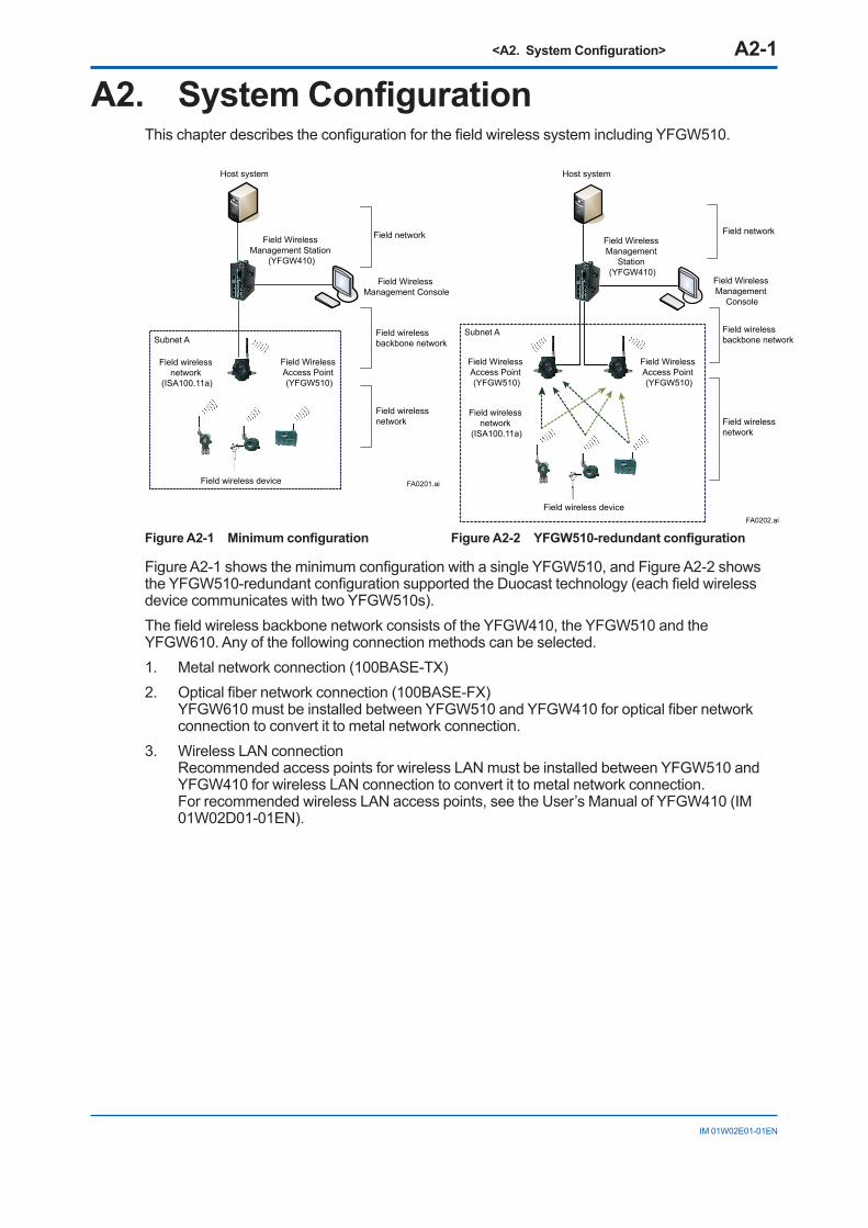
Figure A2-1 Minimum configuration Figure A2-2 YFGW510-redundant configuration
Figure A2-1 shows the minimum configuration with a single YFGW510, and Figure A2-2 shows the YFGW510-redundant configuration supported the Duocast technology (each field wireless device communicates with two YFGW510s).The field wireless backbone network consists of the YFGW410, the YFGW510 and the YFGW610. Any of the following connection methods can be selected.1. Metal network connection (100BASE-TX)2. Optical fiber network connection (100BASE-FX)
YFGW610 must be installed between YFGW510 and YFGW410 for optical fiber network connection to convert it to metal network connection.
3. Wireless LAN connection Recommended access points for wireless LAN must be installed between YFGW510 and YFGW410 for wireless LAN connection to convert it to metal network connection. For recommended wireless LAN access points, see the User’s Manual of YFGW410 (IM 01W02D01-01EN).
<A2. System Configuration> A2-2
IM 01W02E01-01EN
FA0203.ai
Field network
Information network (Ethernet)
NTP serverField wireless management PCField Wireless Management Console
PRMHIS/ENGHIS
Field Wireless Management
Station (YFGW410)
Layer 2 switchLayer 2 switch
Control network (Ethernet)
Cable for redundancy
Layer 2 switch (IEEE 1588)
Layer 2 switch (IEEE 1588)
Layer 2 switch (IEEE 1588)
Layer 2 switch (IEEE 1588)
Layer 2 switch (IEEE 1588)
Layer 2 switch (IEEE 1588)
Field wireless subnet B
Field wireless subnet A
Field wireless backbone network
Field wireless network
Field WirelessAccess Point(YFGW510)
Field wireless device
Field wireless network
(ISA100.11a)
Field WirelessAccess Point(YFGW510)Field Wireless
Access Point(YFGW510)
Field WirelessAccess Point(YFGW510)
Field wirelessnetwork
(ISA100.11a)
Field wireless device
Layer 3 switchFCSALE111 x 2
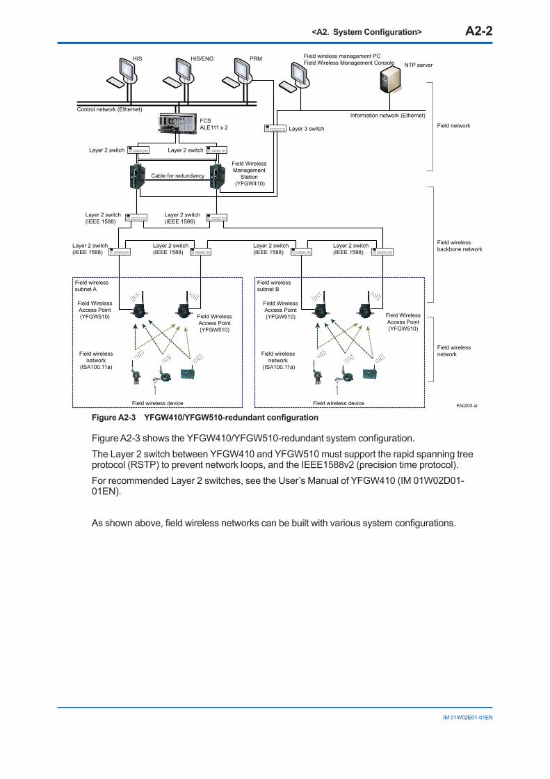
Figure A2-3 YFGW410/YFGW510-redundant configuration
Figure A2-3 shows the YFGW410/YFGW510-redundant system configuration.The Layer 2 switch between YFGW410 and YFGW510 must support the rapid spanning tree protocol (RSTP) to prevent network loops, and the IEEE1588v2 (precision time protocol).For recommended Layer 2 switches, see the User’s Manual of YFGW410 (IM 01W02D01-01EN).
As shown above, field wireless networks can be built with various system configurations.
<B1. Functions of YFGW510> B1-1
IM 01W02E01-01EN
PART-B. FUNCTIONS OF YFGW510B1. Functions of YFGW510
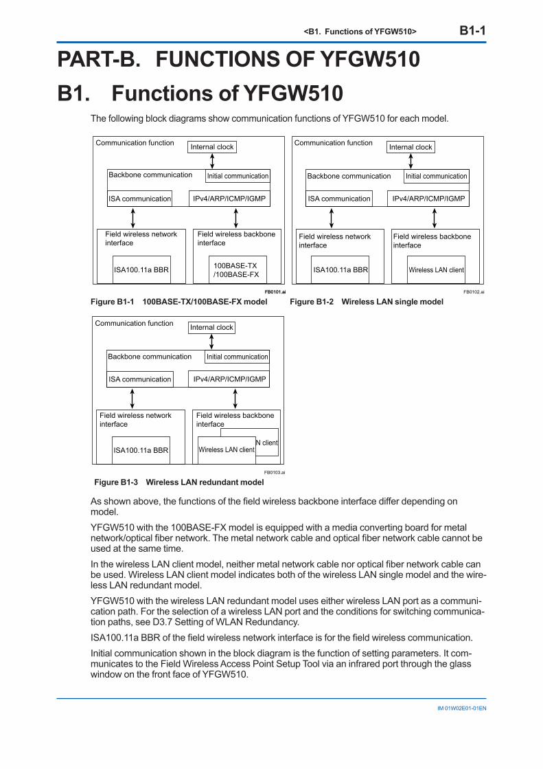
The following block diagrams show communication functions of YFGW510 for each model.
FB0101.aiFB0101.ai
Communication function
Backbone communication
Internal clock
Initial communication
IPv4/ARP/ICMP/IGMPISA communication
Field wireless network interface
Field wireless backbone interface
ISA100.11a BBR 100BASE-TX/100BASE-FX
FB0102.ai
Communication function
Backbone communication
Internal clock
Initial communication
IPv4/ARP/ICMP/IGMPISA communication
Field wireless network interface
Field wireless backbone interface
ISA100.11a BBR Wireless LAN client
Figure B1-1 100BASE-TX/100BASE-FX model Figure B1-2 Wireless LAN single model
FB0103.ai
Communication function
Backbone communication
Internal clock
Initial communication
IPv4/ARP/ICMP/IGMPISA communication
Field wireless network interface
Field wireless backbone interface
ISA100.11a BBRWireless LAN client
Wireless LAN client
Figure B1-3 Wireless LAN redundant model
As shown above, the functions of the field wireless backbone interface differ depending on model.YFGW510 with the 100BASE-FX model is equipped with a media converting board for metal network/optical fiber network. The metal network cable and optical fiber network cable cannot be used at the same time.In the wireless LAN client model, neither metal network cable nor optical fiber network cable can be used. Wireless LAN client model indicates both of the wireless LAN single model and the wire-less LAN redundant model.YFGW510 with the wireless LAN redundant model uses either wireless LAN port as a communi-cation path. For the selection of a wireless LAN port and the conditions for switching communica-tion paths, see D3.7 Setting of WLAN Redundancy.ISA100.11a BBR of the field wireless network interface is for the field wireless communication.Initial communication shown in the block diagram is the function of setting parameters. It com-municates to the Field Wireless Access Point Setup Tool via an infrared port through the glass window on the front face of YFGW510.
<B2. Structure and Parts of YFGW510> B2-1
IM 01W02E01-01EN
B2. Structure and Parts of YFGW510
B2.1 Front View
FB0201.ai
ISA100.11a antenna
Wireless LAN antenna 1
Wireless LAN antenna 2
Tag plate for explosion protected type
Status indicator LED (ACT, LAN, ISA)
Wireless LAN status indicator (C1, C2, AP)
Infrared port
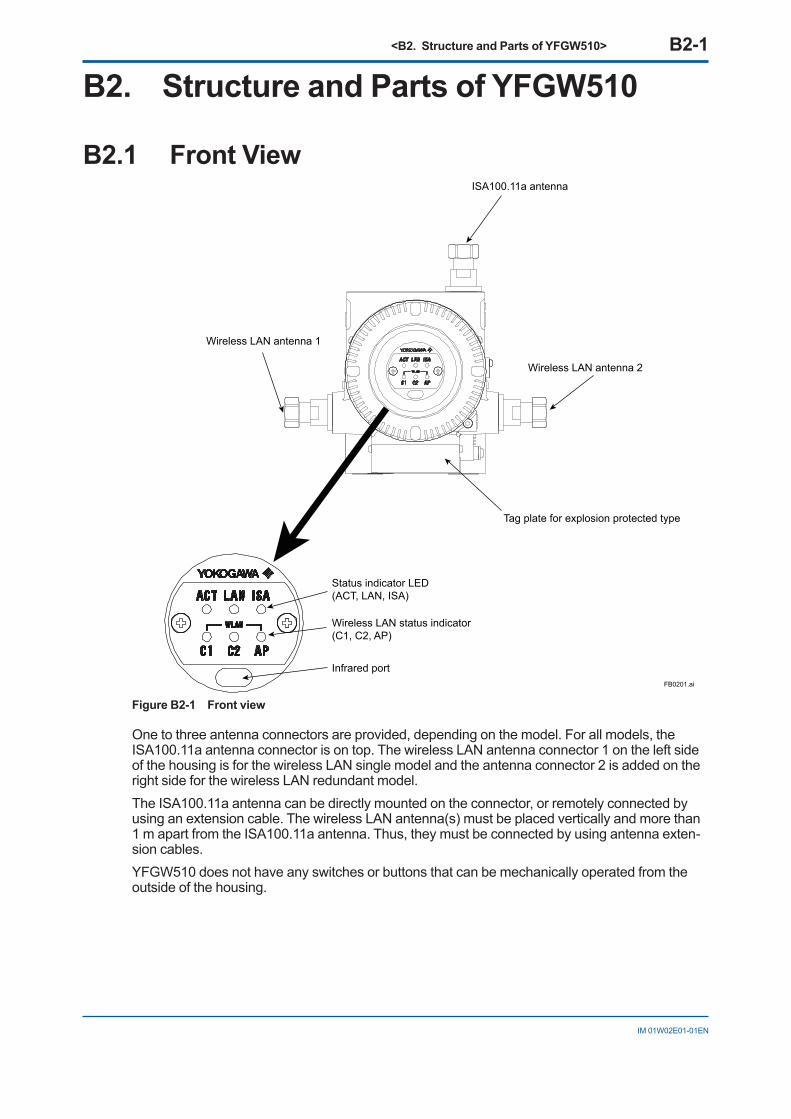
Figure B2-1 Front view
One to three antenna connectors are provided, depending on the model. For all models, the ISA100.11a antenna connector is on top. The wireless LAN antenna connector 1 on the left side of the housing is for the wireless LAN single model and the antenna connector 2 is added on the right side for the wireless LAN redundant model.The ISA100.11a antenna can be directly mounted on the connector, or remotely connected by using an extension cable. The wireless LAN antenna(s) must be placed vertically and more than 1 m apart from the ISA100.11a antenna. Thus, they must be connected by using antenna exten-sion cables.YFGW510 does not have any switches or buttons that can be mechanically operated from the outside of the housing.
<B2. Structure and Parts of YFGW510> B2-2
IM 01W02E01-01EN
B2.2 Rear View
FB0202-1.ai
ISA100.11a antenna
Wireless LAN antenna 1Wireless LAN antenna 2
RJ-45 connectorGround terminal
Power supply terminal
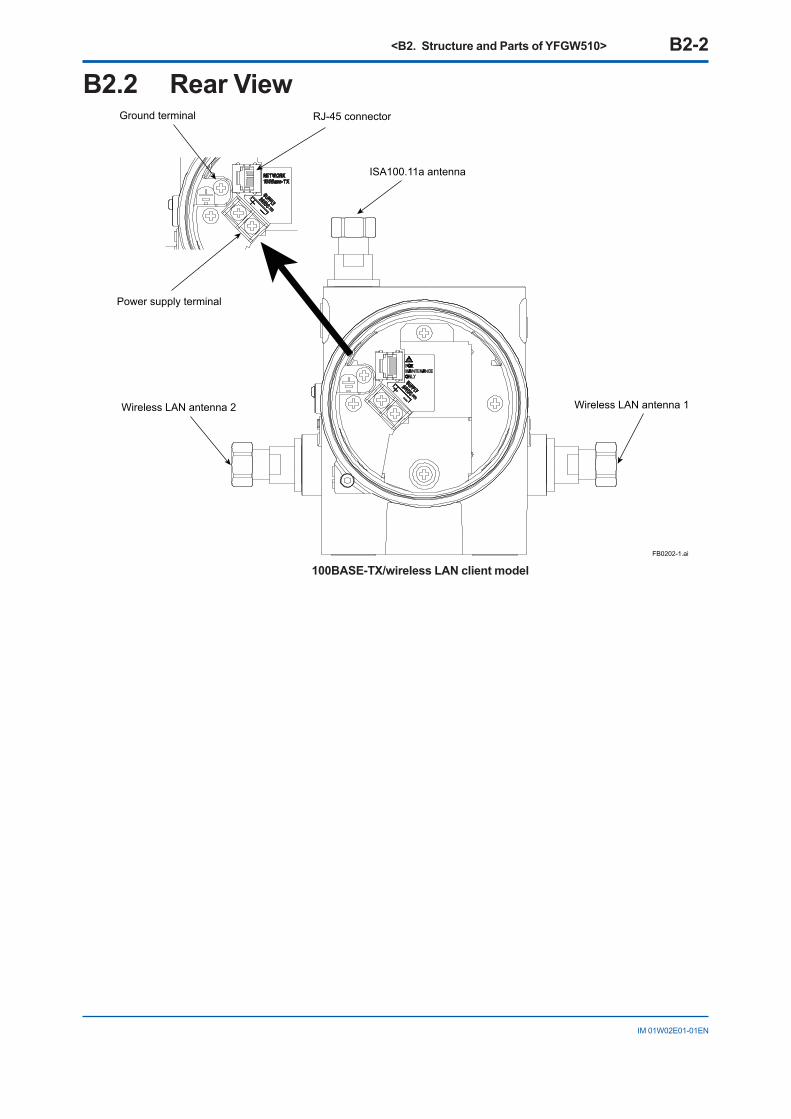
100BASE-TX/wireless LAN client model
<B2. Structure and Parts of YFGW510> B2-3
IM 01W02E01-01EN
FB0202-2.ai
ISA100.11a antenna
SC connectorPower supply terminal
Ground terminal
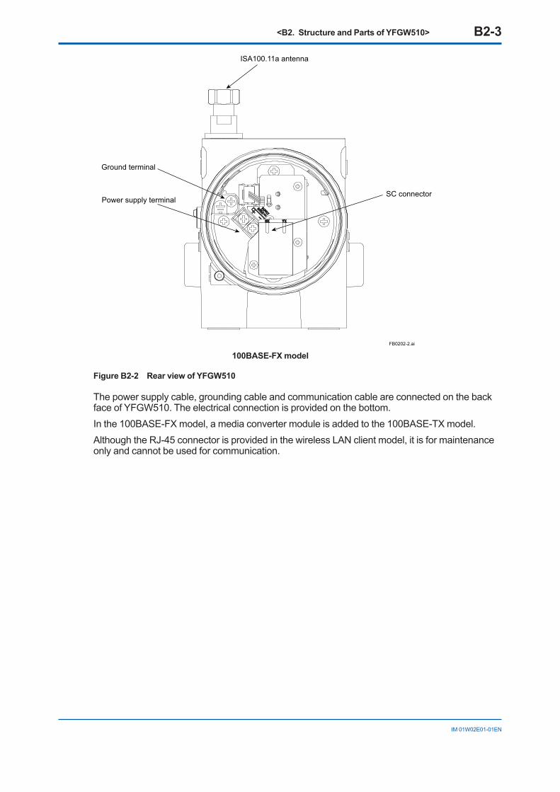
100BASE-FX model
Figure B2-2 Rear view of YFGW510
The power supply cable, grounding cable and communication cable are connected on the back face of YFGW510. The electrical connection is provided on the bottom.In the 100BASE-FX model, a media converter module is added to the 100BASE-TX model.Although the RJ-45 connector is provided in the wireless LAN client model, it is for maintenance only and cannot be used for communication.
<B2. Structure and Parts of YFGW510> B2-4
IM 01W02E01-01EN
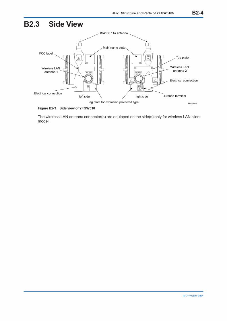
B2.3 Side View
FB0203.ai
ISA100.11a antenna
Tag plate
Wireless LAN antenna 2
Electrical connection
Tag plate for explosion protected type
FCC label
Main name plate
Ground terminalright sideleft sideElectrical connection
Wireless LAN antenna 1
Figure B2-3 Side view of YFGW510
The wireless LAN antenna connector(s) are equipped on the side(s) only for wireless LAN client model.
<B3. LED Display Function> B3-1
IM 01W02E01-01EN
B3. LED Display Function
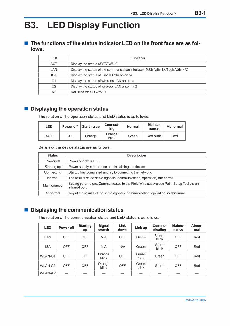
n The functions of the status indicator LED on the front face are as fol-lows.
LED FunctionACT Display the status of YFGW510LAN Display the status of the communication interface (100BASE-TX/100BASE-FX)ISA Display the status of ISA100.11a antennaC1 Display the status of wireless LAN antenna 1C2 Display the status of wireless LAN antenna 2AP Not used for YFGW510
n Displaying the operation statusThe relation of the operation status and LED status is as follows.
LED Power off Starting up Connect-ing Normal Mainte-
nance Abnormal
ACT OFF Orange Orange blink Green Red blink Red
Details of the device status are as follows.
Status DescriptionPower off Power supply is OFF.
Starting up Power supply is turned on and initializing the device.Connecting Startup has completed and try to connect to the network.
Normal The results of the self-diagnosis (communication, operation) are normal.
Maintenance Setting parameters. Communicates to the Field Wireless Access Point Setup Tool via an infrared port.
Abnormal Any of the results of the self-diagnosis (communication, operation) is abnormal.
n Displaying the communication statusThe relation of the communication status and LED status is as follows.
LED Power off Starting up
Signal search
Link down Link up Commu-
nicatingMainte-nance
Abnor-mal
LAN OFF OFF N/A OFF Green Green blink OFF Red
ISA OFF OFF N/A N/A Green Green blink OFF Red
WLAN-C1 OFF OFF Orange blink OFF Green
blink Green OFF Red
WLAN-C2 OFF OFF Orange blink OFF Green
blink Green OFF Red
WLAN-AP ― ― ― ― ― ― ― ―

<B4. Mechanical Operating Parts> B4-1
IM 01W02E01-01EN
B4. Mechanical Operating PartsYFGW510 does not have any switches or buttons that can be mechanically operated from out-side of the housing.
<B5. Checking the Product> B5-1
IM 01W02E01-01EN
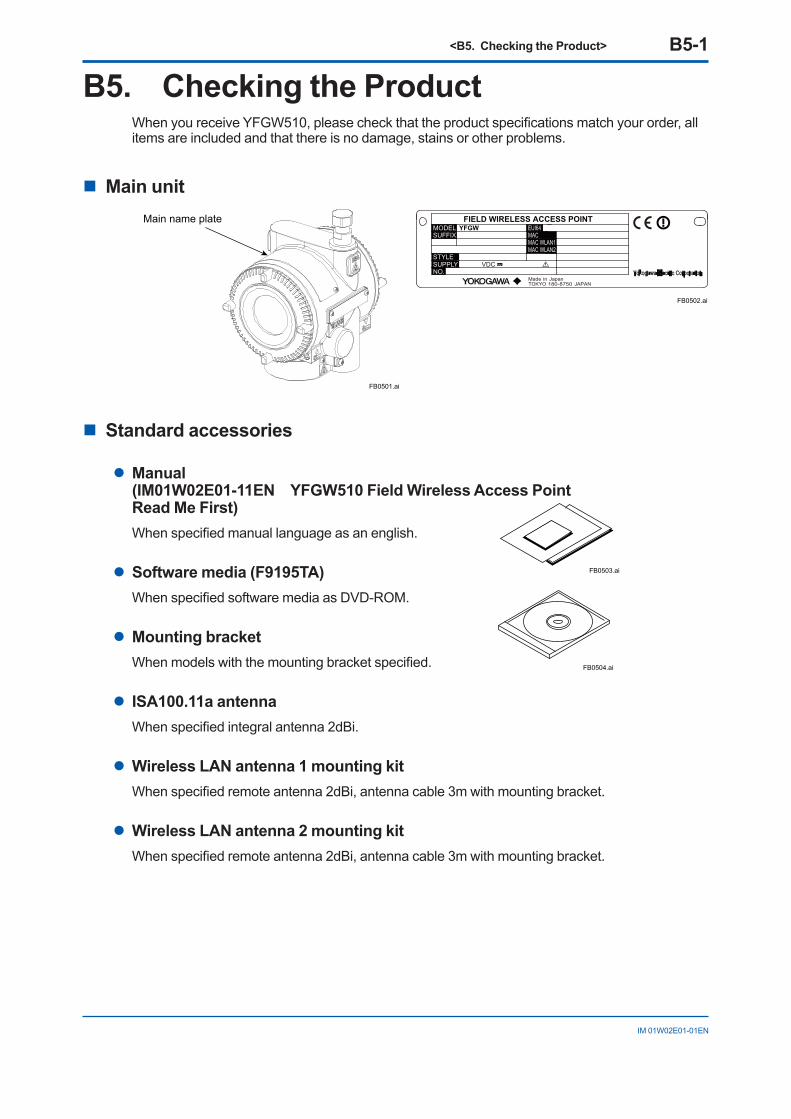
B5. Checking the ProductWhen you receive YFGW510, please check that the product specifications match your order, all items are included and that there is no damage, stains or other problems.
n Main unit
FB0501.ai
Main name plate
n Standard accessories
l Manual (IM01W02E01-11EN YFGW510 Field Wireless Access Point Read Me First)When specified manual language as an english.
l Software media (F9195TA)When specified software media as DVD-ROM.
l Mounting bracketWhen models with the mounting bracket specified.
l ISA100.11a antennaWhen specified integral antenna 2dBi.
l Wireless LAN antenna 1 mounting kitWhen specified remote antenna 2dBi, antenna cable 3m with mounting bracket.
l Wireless LAN antenna 2 mounting kitWhen specified remote antenna 2dBi, antenna cable 3m with mounting bracket.
FIELD WIRELESS ACCESS POINT
VDC
YFGW
MadeTOKYO
Japanin180-8750 JAPAN
STYLESUPPLYNO.
MAC WLMAC WLMACEUI64
AN1AN2
MODELSUFFIX
FB0502.ai
FB0503.ai
FB0504.ai
<C1. Installation Environment> C1-1
IM 01W02E01-01EN
PART-C. INSTALLATIONThis part describes installation for YFGW510.Follow the steps below to use of the product.1. Installation of YFGW5102. Wiring of the power supply, grounding cable, signal cables and mounting/wiring of
antenna(s)
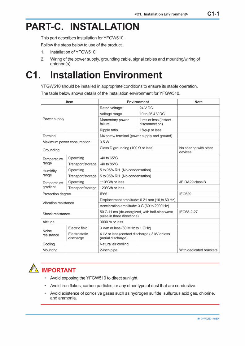
C1. Installation EnvironmentYFGW510 should be installed in appropriate conditions to ensure its stable operation.The table below shows details of the installation environment for YFGW510.
Item Environment Note
Power supply
Rated voltage 24 V DCVoltage range 10 to 26.4 V DCMomentary power failure
1 ms or less (instant disconnection)
Ripple ratio 1%p-p or lessTerminal M4 screw terminal (power supply and ground)Maximum power consumption 3.5 W
Grounding Class D grounding (100 Ω or less) No sharing with other devices
Temperature range
Operating -40 to 65°CTransport/storage -40 to 85°C
Humidity range
Operating 5 to 95% RH (No condensation)Transport/storage 5 to 95% RH (No condensation)
Temperature gradient
Operating ±10°C/h or less JEIDA29 class BTransport/storage ±20°C/h or less
Protection degree IP66 IEC529
Vibration resistanceDisplacement amplitude: 0.21 mm (10 to 60 Hz)Acceleration amplitude: 3 G (60 to 2000 Hz)
Shock resistance 50 G 11 ms (de-energized, with half-sine wave pulse in three directions)
IEC68-2-27
Altitude 3000 m or less
Noise resistance
Electric field 3 V/m or less (80 MHz to 1 GHz)Electrostatic discharge
4 kV or less (contact discharge), 8 kV or less (aerial discharge)
Cooling Natural air coolingMounting 2-inch pipe With dedicated brackets
IMPORTANT• Avoid exposing the YFGW510 to direct sunlight.
• Avoid iron flakes, carbon particles, or any other type of dust that are conductive.
• Avoid existence of corrosive gases such as hydrogen sulfide, sulfurous acid gas, chlorine, and ammonia.
<C1. Installation Environment> C1-2
IM 01W02E01-01EN
IMPORTANTThis product is equipped with a wireless module which is designated as a certification of con-struction type as a wireless facility for 2.4 GHz band low-power data communication system of the Radio Act.Refer to G1.3 Regulatory Compliance Statements for detail.Before use, confirm that the location of installation satisfies the above standard.
IMPORTANT• Microwave ovens and other industrial, scientific and medical equipment, as well as local
wireless stations (license required) and specific low-power wireless stations (license not required) for identifying mobile objects used in the production line of a factory, use the same frequency band as this product. Prevent interference with other wireless stations.
• Check that local wireless stations and specific low-power wireless stations are not being used in the vicinity before using this product.
• If this product causes radio interference in a local wireless station used for identifying mobile objects, change the working frequency or stop the emission of radio waves immediately. For details on how to prevent radio interference, contact our service office.
WARNING• To satisfy degree of protection provided by enclosure IP66, apply suitable devices to the
electrical connection port.
<C2. Power Supply and Grounding> C2-1
IM 01W02E01-01EN
C2. Power Supply and GroundingAn appropriate power supply is necessary for the stable operation of YFGW510.
C2.1 Power SupplyConnect the power source to the power supply terminal in the device.
SEE ALSO For details of the power supply and power consumption of YFGW510, see C1. Installation Environment.
n Inrush CurrentWhen starting up, inrush current may run into the device. As shown in the table below, this cur-rent is, even though short-lived, significantly larger (10 times or more) than the steady state cur-rent. Make sure that the power supply and protector can endure the inrush current.
Item Specification RemarksInrush current 8 A (5 ms or less) At 26.4 V DC
SEE ALSO For details of power supply wiring, see C5.1 Power Supply Cable Connection.
IMPORTANTYFGW510 does not have a power switch. Provide a breaker or switch for the power line to turn ON/OFF the device.
• Configuration data may be corrupted if a power failure occurs during download to YFGW410, YFGW510 and field wireless devices. Configuration data is not corrupted even if a power failure occurs at the time of the usual operation.
• Please supply the power from the permanent power supply to avoid.
C2.2 GroundingAppropriate grounding is necessary for the stable operation of YFGW510. Class D grounding (the third class grounding) with the grounding resistance of 100 Ω or less is necessary. To con-nect the grounding cable to YFGW510 directly, use the ground terminal on the right side of the housing.
SEE ALSO For details of ground wiring, see C5.2 Grounding Cable Connection.
<C3. Requirements for Installation> C3-1
IM 01W02E01-01EN
C3. Requirements for Installation
C3.1 Requirements for Installation LocationsThe installation of YFGW510 and field wireless devices must meet the following conditions:
• The field wireless equipment should be mounted in the place where no obstacle exists around the antenna. Especially, YFGW510 should be mounted in the condition that no ob-stacle exists around the antenna.
• If there is a pipe for mounting or plumbing in the direction except for the communication partners, the antenna should be more than 30 cm apart from them.
• When the wireless LAN antenna or field wireless antenna do not meet above requirements, use an extension cable to place the antenna where radio waves will not be affected by ob-stacles.
• All antennas must be in the upright position.
• The antenna of field wireless equipment must be installed at least 1.5 m above the ground (floor)
• The YFGW510 should be installed at a location as close as possible to the center of the field wireless network.
• Ensure that the field wireless devices that are located within the wireless communication range are within the line of sight of each other. In the star topology, the YFGW510 must meet this condition.
<C3. Requirements for Installation> C3-2
IM 01W02E01-01EN
C3.2 Notes on InstallationPay attention to the following points at the installation of YFGW510 and field wireless devices.
n Installation LocationThis device is designed to work under the severe environmental condition. However, it is neces-sary to pay attention to the following conditions for the stable and long-term precise operation.
l Exposure to Direct Sunlight If the device is placed at a location that may be exposed to direct sunlight, it is necessary
to make the insulation measure. However, the antenna must be covered with the material which does not block the radio wave.
l Ambient Temperature Avoid locations subject to wide temperature variations or a significant temperature gradient.
If the location is exposed to radiant heat from plant equipment, provide adequate thermal insulation and/or ventilation. Do not install the device in a location where high temperature and high humidity may last for a long time.
l Ambient Atmosphere Do not install the device in a corrosive atmosphere. If this cannot be avoided, there must
be adequate ventilation as well as measures to prevent the rain water from penetrating or remaining in the conduits.
l Vibration and Impact Although the device is designed to be resistant to vibration and impact, an installation site
should be selected where vibration and impact are kept to a minimum.
n Installation of Explosion Proof Compliant Device The explosion proof compliant equipment can be installed in the hazardous area of specific gases. This device must be installed in accordance with the regulations of the country where the device is installed.
• Installation: Check that the ambient temperature is not beyond the limit.
• Wiring: Put all the power cables in protective ducts. If possible, also put the network cables (optical fiber cable or metal cable) in protective ducts.
• Maintenance: After confirming that there is no dangerous gas in the ambience, open the housing or protective ducts.
<C4. Mounting> C4-1
IM 01W02E01-01EN
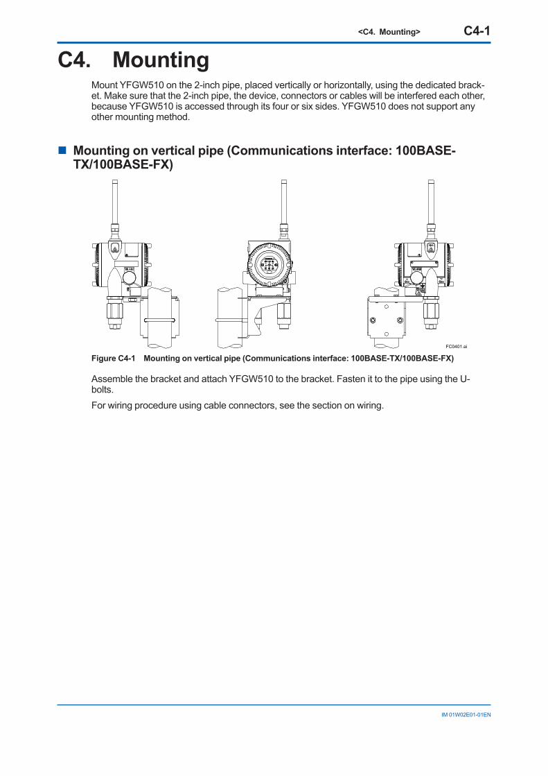
C4. MountingMount YFGW510 on the 2-inch pipe, placed vertically or horizontally, using the dedicated brack-et. Make sure that the 2-inch pipe, the device, connectors or cables will be interfered each other, because YFGW510 is accessed through its four or six sides. YFGW510 does not support any other mounting method.
n Mounting on vertical pipe (Communications interface: 100BASE-TX/100BASE-FX)
FC0401.ai
Figure C4-1 Mounting on vertical pipe (Communications interface: 100BASE-TX/100BASE-FX)
Assemble the bracket and attach YFGW510 to the bracket. Fasten it to the pipe using the U-bolts. For wiring procedure using cable connectors, see the section on wiring.
<C4. Mounting> C4-2
IM 01W02E01-01EN
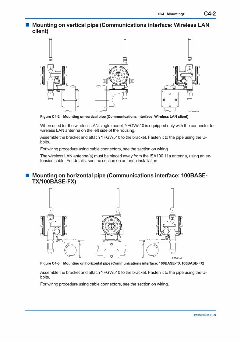
n Mounting on vertical pipe (Communications interface: Wireless LAN client)
FC0402.ai
Figure C4-2 Mounting on vertical pipe (Communications interface: Wireless LAN client)
When used for the wireless LAN single model, YFGW510 is equipped only with the connector for wireless LAN antenna on the left side of the housing.Assemble the bracket and attach YFGW510 to the bracket. Fasten it to the pipe using the U-bolts. For wiring procedure using cable connectors, see the section on wiring.The wireless LAN antenna(s) must be placed away from the ISA100.11a antenna, using an ex-tension cable. For details, see the section on antenna installation
n Mounting on horizontal pipe (Communications interface: 100BASE-TX/100BASE-FX)
FC0403.ai
Figure C4-3 Mounting on horizontal pipe (Communications interface: 100BASE-TX/100BASE-FX)
Assemble the bracket and attach YFGW510 to the bracket. Fasten it to the pipe using the U-bolts. For wiring procedure using cable connectors, see the section on wiring.
<C4. Mounting> C4-3
IM 01W02E01-01EN
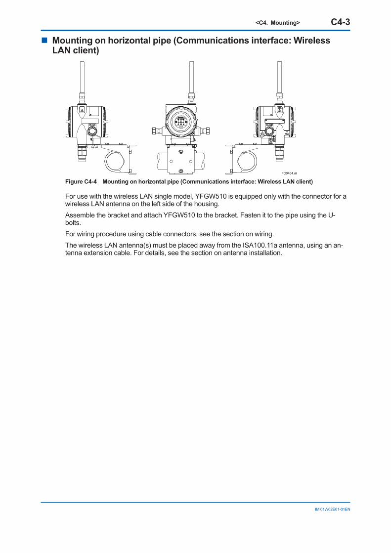
n Mounting on horizontal pipe (Communications interface: Wireless LAN client)
FC0404.ai
Figure C4-4 Mounting on horizontal pipe (Communications interface: Wireless LAN client)
For use with the wireless LAN single model, YFGW510 is equipped only with the connector for a wireless LAN antenna on the left side of the housing.Assemble the bracket and attach YFGW510 to the bracket. Fasten it to the pipe using the U-bolts. For wiring procedure using cable connectors, see the section on wiring.The wireless LAN antenna(s) must be placed away from the ISA100.11a antenna, using an an-tenna extension cable. For details, see the section on antenna installation.
<C5. Wiring> C5-1
IM 01W02E01-01EN
C5. WiringThis chapter describes connection of the power supply cable, grounding cable and network cable to the installed YFGW510, mounting of antennas and cable connection.
• With the cable wiring to the electrical connection port, use a metalic conduit or waterproof glands.
• Apply a non-hardening sealant to the electrical connection port and to the threads on the metal conduit for waterproofing.
• There must be measures to prevent the rain water from penetrating or remaining in the con-duits.
• Use cables with a 70°C rating or higher for explosion-proof devices.
• Explosion-proof device must be wired in compliance with related laws and regulations.
C5.1 Power Supply Cable ConnectionThis section describes power supply cable wiring.l Wiring
Pull the power supply cable into the device through the power cable ground. Connect the power supply cable to the power supply terminal in the device.l Recommended power supply capacity
Output voltage range: 12 to 24V DC (Supplied from power supply to YFGW510)Output capacity: 10 W or more ** When starting up YFGW510, an inrush current flows as described in C2.1 Power Supply. Make sure that the power source has current
output capacity at least three times normal current consumption and enough to withstand the inrush current as described below.
l Inrush current
When power is turned on, an input current flows, which is higher than its normal state. See C2.1 Power Supply about inrush current. Ensure that the power supply and protective devices can withstand this current. l Cable (Insulated for industrial equipment)
Examples• 600 V polyvinyl chloride insulated wires (IV): JIS C3307
• Polyvinyl chloride insulated wires for electrical apparatus (KIV): JIS C3316
• 600 V grade heat-resistant polyvinyl chloride insulated wires (HIV): JIS C3317
• Heatproof vinyl insulated wires VW-1 (UL1015/UL1007)
Wire size• Core: AWG14 to 13 (2 to 2.6 mm2)
Terminal treatment• Ring terminal for M4: With insulation covers
<C5. Wiring> C5-2
IM 01W02E01-01EN
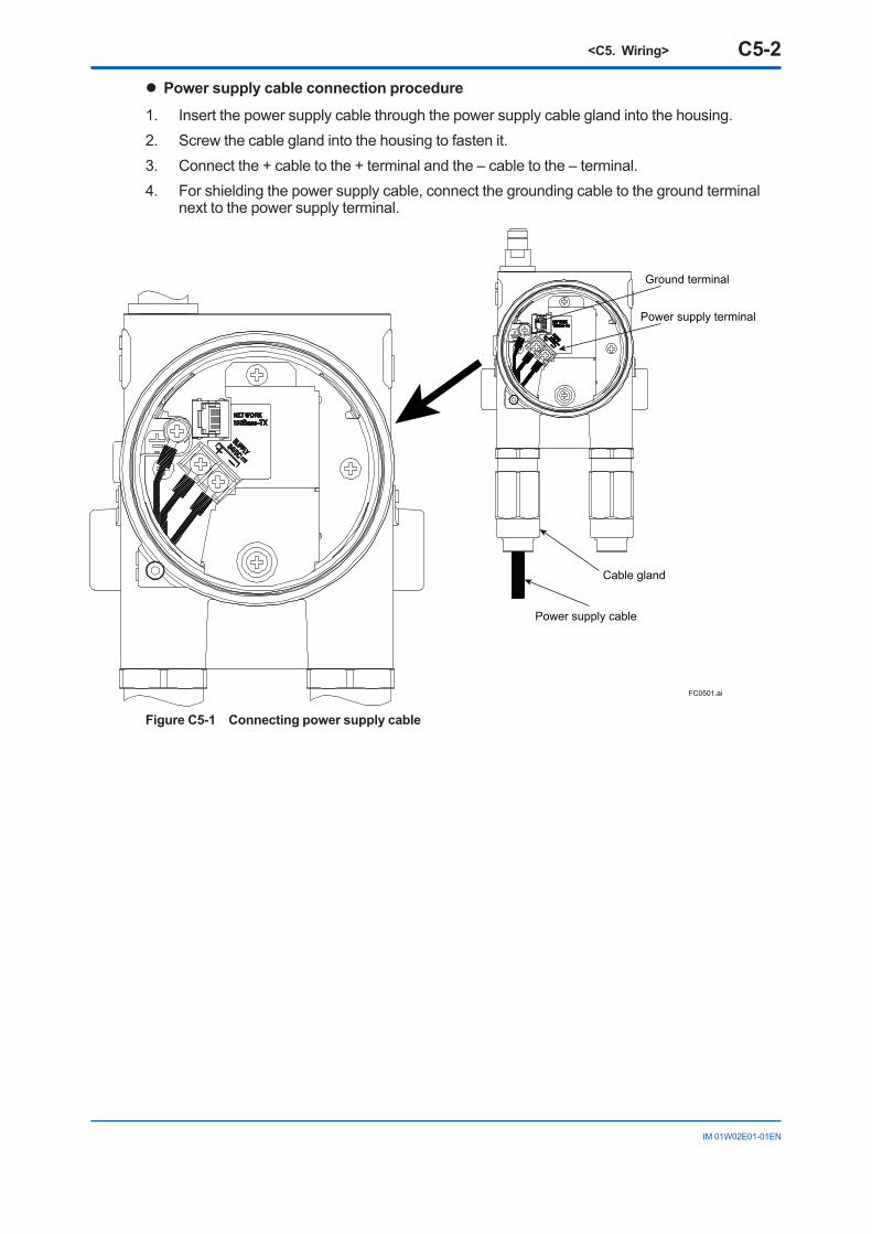
l Power supply cable connection procedure
1. Insert the power supply cable through the power supply cable gland into the housing.2. Screw the cable gland into the housing to fasten it.3. Connect the + cable to the + terminal and the – cable to the – terminal.4. For shielding the power supply cable, connect the grounding cable to the ground terminal
next to the power supply terminal.
FC0501.ai
Ground terminal
Power supply terminal
Power supply cable
Cable gland
Figure C5-1 Connecting power supply cable
<C5. Wiring> C5-3
IM 01W02E01-01EN
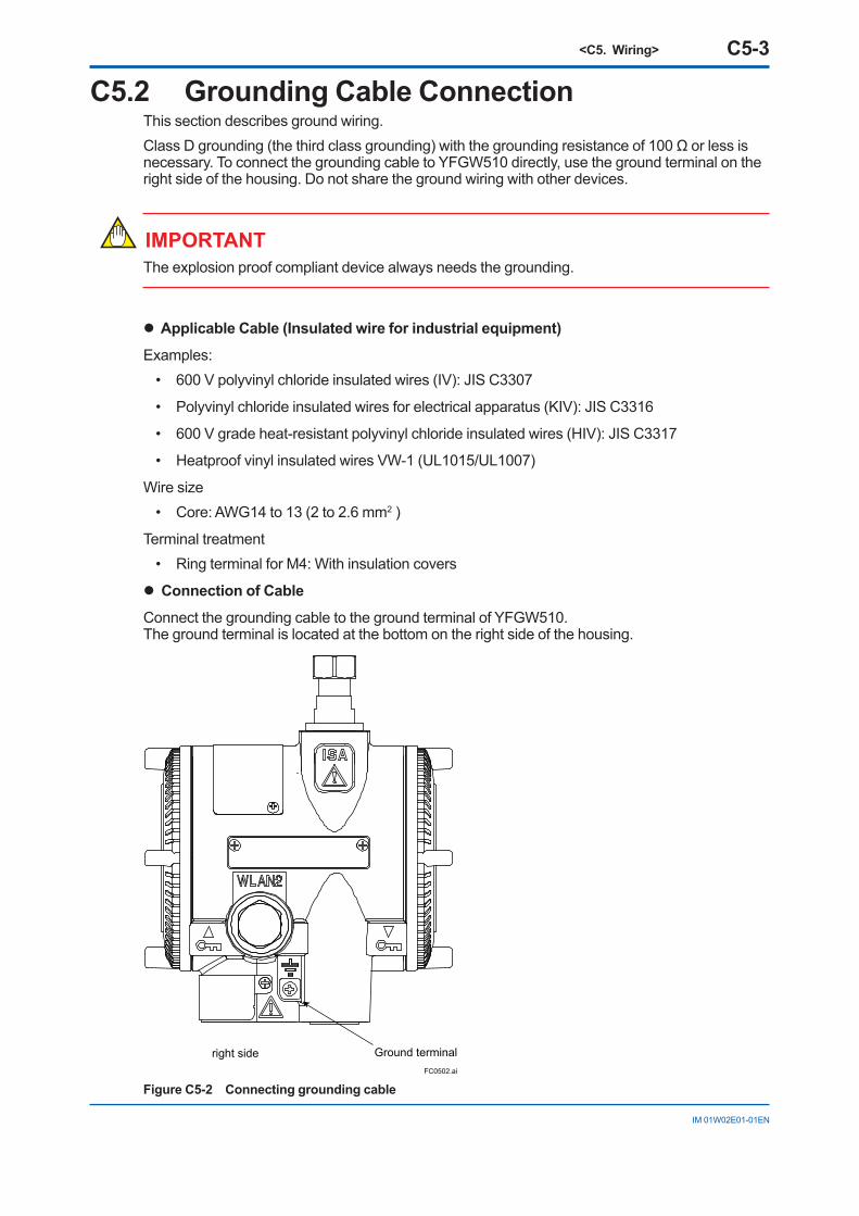
C5.2 Grounding Cable ConnectionThis section describes ground wiring.Class D grounding (the third class grounding) with the grounding resistance of 100 Ω or less is necessary. To connect the grounding cable to YFGW510 directly, use the ground terminal on the right side of the housing. Do not share the ground wiring with other devices.
IMPORTANTThe explosion proof compliant device always needs the grounding.
l Applicable Cable (Insulated wire for industrial equipment)
Examples:• 600 V polyvinyl chloride insulated wires (IV): JIS C3307
• Polyvinyl chloride insulated wires for electrical apparatus (KIV): JIS C3316
• 600 V grade heat-resistant polyvinyl chloride insulated wires (HIV): JIS C3317
• Heatproof vinyl insulated wires VW-1 (UL1015/UL1007)
Wire size• Core: AWG14 to 13 (2 to 2.6 mm2 )
Terminal treatment• Ring terminal for M4: With insulation covers
l Connection of Cable
Connect the grounding cable to the ground terminal of YFGW510. The ground terminal is located at the bottom on the right side of the housing.
FC0502.ai
Ground terminalright side
Figure C5-2 Connecting grounding cable
<C5. Wiring> C5-4
IM 01W02E01-01EN
C5.3 Network Cable ConnectionC5.3.1 Metal Network Cable Connection
l Caution for use with metal network cable
The metal network cable is intended for indoor wiring. In outdoor wiring, it is recommended the optical network cable in order to eliminate the influence of electromagnetic noise due to lightning and keep transmission distance. An optical fiber network cable is recommended if outdoor wiring is required because of transmission range and influence of electromagnetic noise due to lightning or other similar factors.l Cable
ItemSpecification
Metal network cableStandard 100BASE-TX Connector RJ-45 *Cable Category 5 or higherTransmission range 100 m (Max.)
* RJ-45 connector attaching to the YFGW510-side end of the cable is larger than the cable gland hole. The RJ-45 does not go through the gland. Follow wiring procedures as described below.
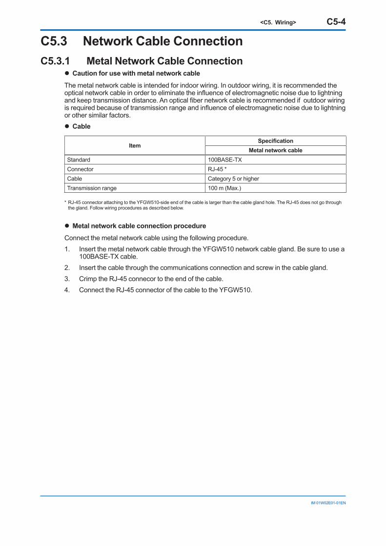
l Metal network cable connection procedure
Connect the metal network cable using the following procedure.1. Insert the metal network cable through the YFGW510 network cable gland. Be sure to use a
100BASE-TX cable.2. Insert the cable through the communications connection and screw in the cable gland.3. Crimp the RJ-45 connecor to the end of the cable.4. Connect the RJ-45 connector of the cable to the YFGW510.
<C5. Wiring> C5-5
IM 01W02E01-01EN
FC0503.ai
Metal network cable
Cable Gland for Communication
RJ-45 connector
Figure C5-3 Connecting metal network cable
C5.3.2 Optical Network Cable Connectionl Cable
ItemSpecification
Optical network cableStandard 100BASE-FX Connector SC connector (1-pole × 2)*
CableMultimode fiber (central wavelength: 1300 nm)50/125 µm or 62.5/125 µmThe inner tension member must be nonmetal, such as FRP.
Transmission range 2 km (Max.)
* A double ferrule SC connector does not go through the connection hole. Be sure to use a short-boot SC connector.
IMPORTANTTo connect YFGW410 and YFGW510 using an optical network cable, the YFGW610 is required for YFGW410. YFGW610 is used for conversion between 100BASE-TX and 100BASE-FX.
<C5. Wiring> C5-6
IM 01W02E01-01EN
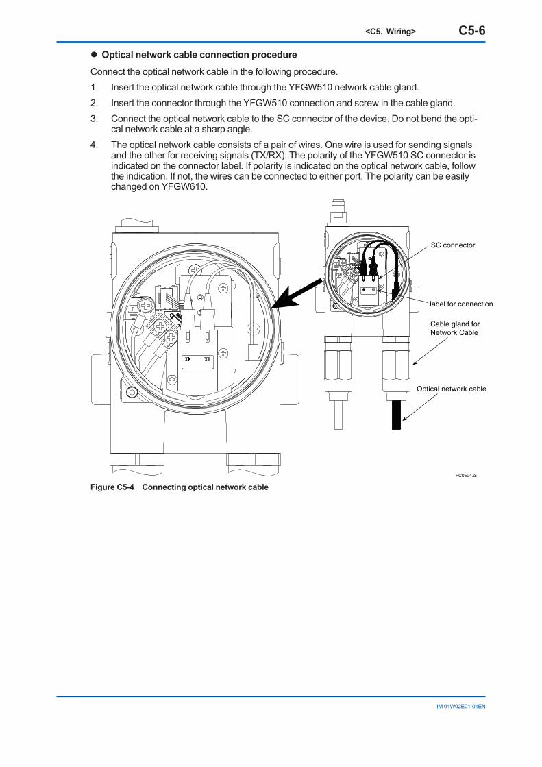
l Optical network cable connection procedure
Connect the optical network cable in the following procedure.1. Insert the optical network cable through the YFGW510 network cable gland.2. Insert the connector through the YFGW510 connection and screw in the cable gland.3. Connect the optical network cable to the SC connector of the device. Do not bend the opti-
cal network cable at a sharp angle. 4. The optical network cable consists of a pair of wires. One wire is used for sending signals
and the other for receiving signals (TX/RX). The polarity of the YFGW510 SC connector is indicated on the connector label. If polarity is indicated on the optical network cable, follow the indication. If not, the wires can be connected to either port. The polarity can be easily changed on YFGW610.
FC0504.ai
SC connector
label for connection
Optical network cable
Cable gland for Network Cable
Figure C5-4 Connecting optical network cable
<C5. Wiring> C5-7
IM 01W02E01-01EN
C5.4 Installation and Wiring of AntennaThis section describes mounting of antennas to YFGW510, and installation of remote antennas and their wiring.
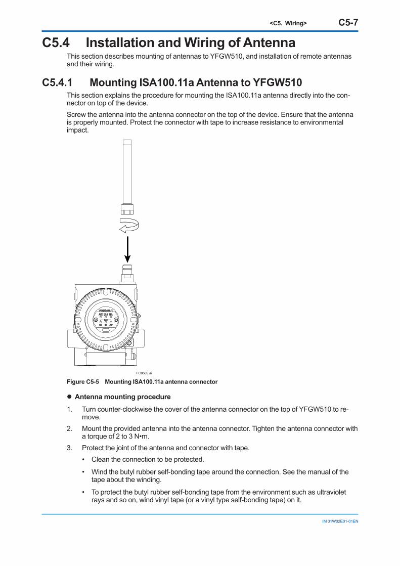
C5.4.1 Mounting ISA100.11a Antenna to YFGW510This section explains the procedure for mounting the ISA100.11a antenna directly into the con-nector on top of the device.Screw the antenna into the antenna connector on the top of the device. Ensure that the antenna is properly mounted. Protect the connector with tape to increase resistance to environmental impact.
FC0505.ai
Figure C5-5 Mounting ISA100.11a antenna connector
l Antenna mounting procedure
1. Turn counter-clockwise the cover of the antenna connector on the top of YFGW510 to re-move.
2. Mount the provided antenna into the antenna connector. Tighten the antenna connector with a torque of 2 to 3 N•m.
3. Protect the joint of the antenna and connector with tape.• Clean the connection to be protected.
• Wind the butyl rubber self-bonding tape around the connection. See the manual of the tape about the winding.
• To protect the butyl rubber self-bonding tape from the environment such as ultraviolet rays and so on, wind vinyl tape (or a vinyl type self-bonding tape) on it.
<C5. Wiring> C5-8
IM 01W02E01-01EN
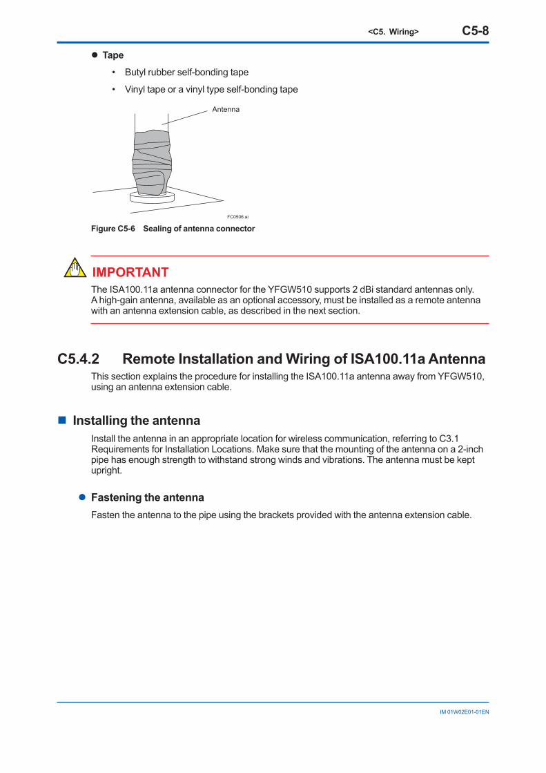
l Tape
• Butyl rubber self-bonding tape
• Vinyl tape or a vinyl type self-bonding tape
Antenna
FC0506.ai
Figure C5-6 Sealing of antenna connector
IMPORTANTThe ISA100.11a antenna connector for the YFGW510 supports 2 dBi standard antennas only. A high-gain antenna, available as an optional accessory, must be installed as a remote antenna with an antenna extension cable, as described in the next section.
C5.4.2 Remote Installation and Wiring of ISA100.11a AntennaThis section explains the procedure for installing the ISA100.11a antenna away from YFGW510, using an antenna extension cable.
n Installing the antennaInstall the antenna in an appropriate location for wireless communication, referring to C3.1 Requirements for Installation Locations. Make sure that the mounting of the antenna on a 2-inch pipe has enough strength to withstand strong winds and vibrations. The antenna must be kept upright.
l Fastening the antennaFasten the antenna to the pipe using the brackets provided with the antenna extension cable.
<C5. Wiring> C5-9
IM 01W02E01-01EN
Bracket
ISA100.11a antenna
Antenna Extension Cable
2-inch pipe
U Bolt
Nut
Nut
Bracket
Antenna Extension Cable
ISA100.11a antenna2-inch pipe
FC0507.ai
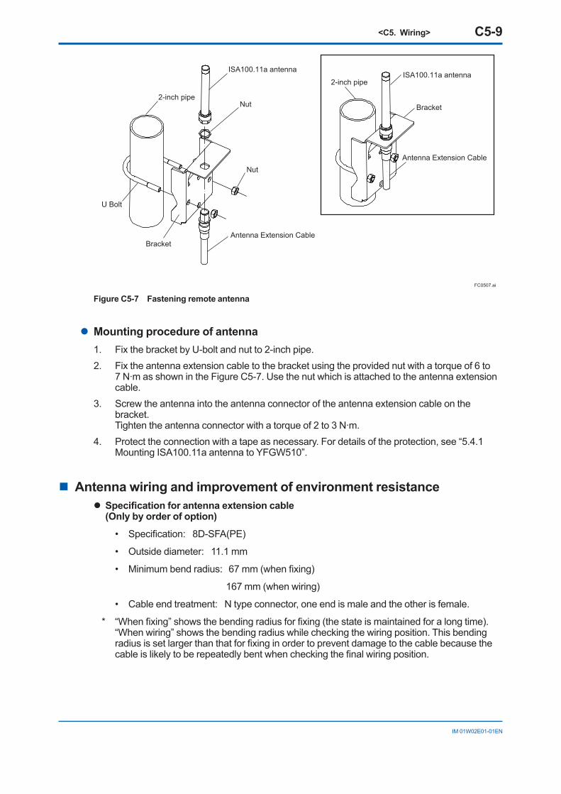
Figure C5-7 Fastening remote antenna
l Mounting procedure of antenna1. Fix the bracket by U-bolt and nut to 2-inch pipe.2. Fix the antenna extension cable to the bracket using the provided nut with a torque of 6 to
7 N∙m as shown in the Figure C5-7. Use the nut which is attached to the antenna extension cable.
3. Screw the antenna into the antenna connector of the antenna extension cable on the bracket. Tighten the antenna connector with a torque of 2 to 3 N∙m.
4. Protect the connection with a tape as necessary. For details of the protection, see “5.4.1 Mounting ISA100.11a antenna to YFGW510”.
n Antenna wiring and improvement of environment resistancel Specification for antenna extension cable
(Only by order of option)
• Specification: 8D-SFA(PE)
• Outside diameter: 11.1 mm
• Minimum bend radius: 67 mm (when fixing)
167 mm (when wiring)
• Cable end treatment: N type connector, one end is male and the other is female.
* “When fixing” shows the bending radius for fixing (the state is maintained for a long time). “When wiring” shows the bending radius while checking the wiring position. This bending radius is set larger than that for fixing in order to prevent damage to the cable because the cable is likely to be repeatedly bent when checking the final wiring position.
<C5. Wiring> C5-10
IM 01W02E01-01EN
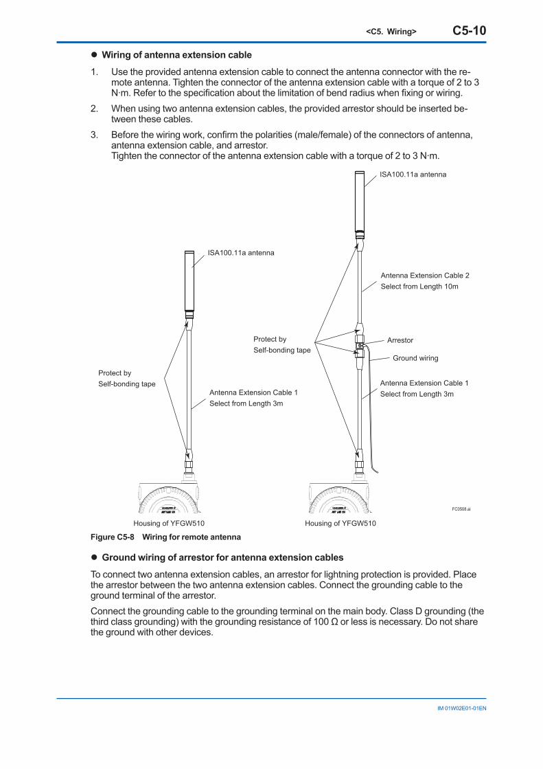
l Wiring of antenna extension cable
1. Use the provided antenna extension cable to connect the antenna connector with the re-mote antenna. Tighten the connector of the antenna extension cable with a torque of 2 to 3 N∙m. Refer to the specification about the limitation of bend radius when fixing or wiring.
2. When using two antenna extension cables, the provided arrestor should be inserted be-tween these cables.
3. Before the wiring work, confirm the polarities (male/female) of the connectors of antenna, antenna extension cable, and arrestor. Tighten the connector of the antenna extension cable with a torque of 2 to 3 N∙m.
ISA100.11a antenna
Antenna Extension Cable 2Select from Length 10m
Antenna Extension Cable 1Select from Length 3mAntenna Extension Cable 1
Select from Length 3m
ISA100.11a antenna
Arrestor
Ground wiring
Protect by Self-bonding tape
Protect by Self-bonding tape
FC0508.ai
Housing of YFGW510 Housing of YFGW510
Figure C5-8 Wiring for remote antenna
l Ground wiring of arrestor for antenna extension cables
To connect two antenna extension cables, an arrestor for lightning protection is provided. Place the arrestor between the two antenna extension cables. Connect the grounding cable to the ground terminal of the arrestor.Connect the grounding cable to the grounding terminal on the main body. Class D grounding (the third class grounding) with the grounding resistance of 100 Ω or less is necessary. Do not share the ground with other devices.
<C5. Wiring> C5-11
IM 01W02E01-01EN
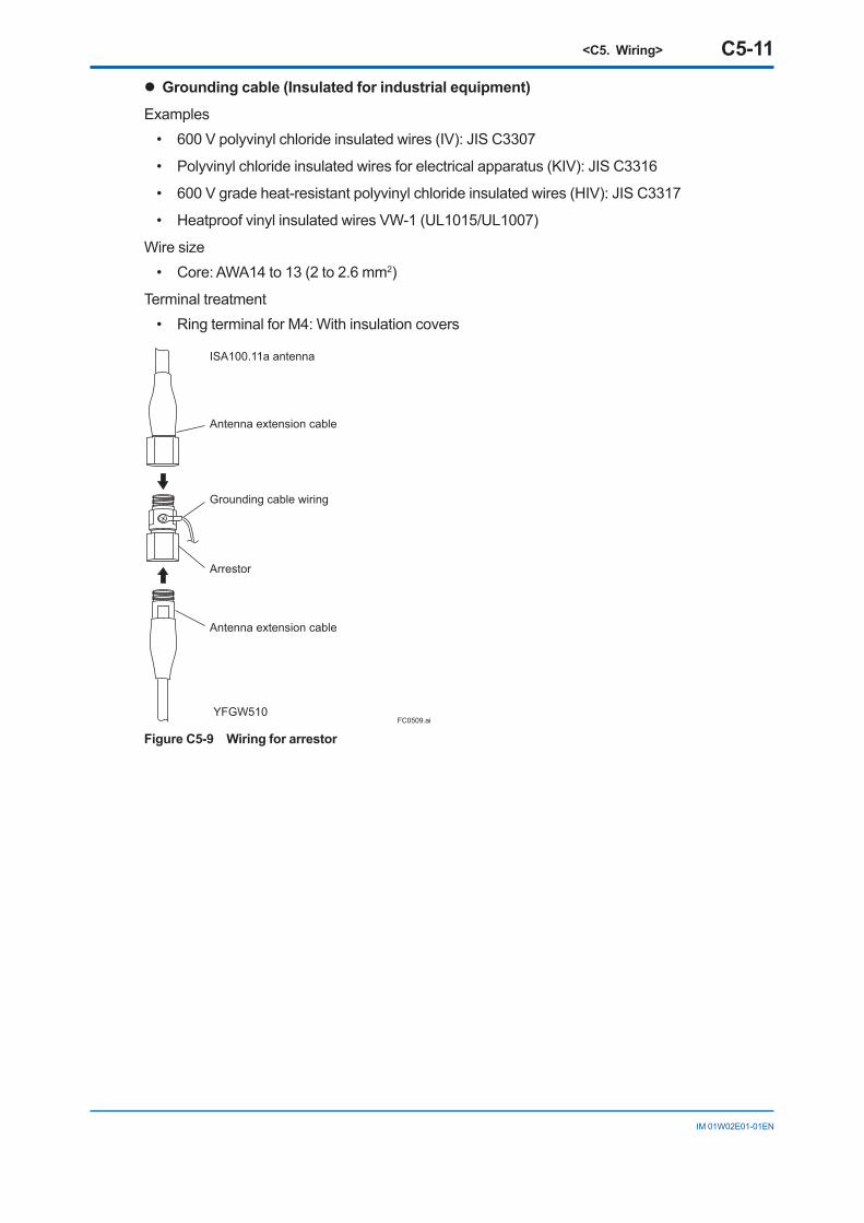
l Grounding cable (Insulated for industrial equipment)
Examples• 600 V polyvinyl chloride insulated wires (IV): JIS C3307
• Polyvinyl chloride insulated wires for electrical apparatus (KIV): JIS C3316
• 600 V grade heat-resistant polyvinyl chloride insulated wires (HIV): JIS C3317
• Heatproof vinyl insulated wires VW-1 (UL1015/UL1007)
Wire size• Core: AWA14 to 13 (2 to 2.6 mm2)
Terminal treatment• Ring terminal for M4: With insulation covers
FC0509.ai
ISA100.11a antenna
YFGW510
Antenna extension cable
Grounding cable wiring
Arrestor
Antenna extension cable
Figure C5-9 Wiring for arrestor
<C5. Wiring> C5-12
IM 01W02E01-01EN
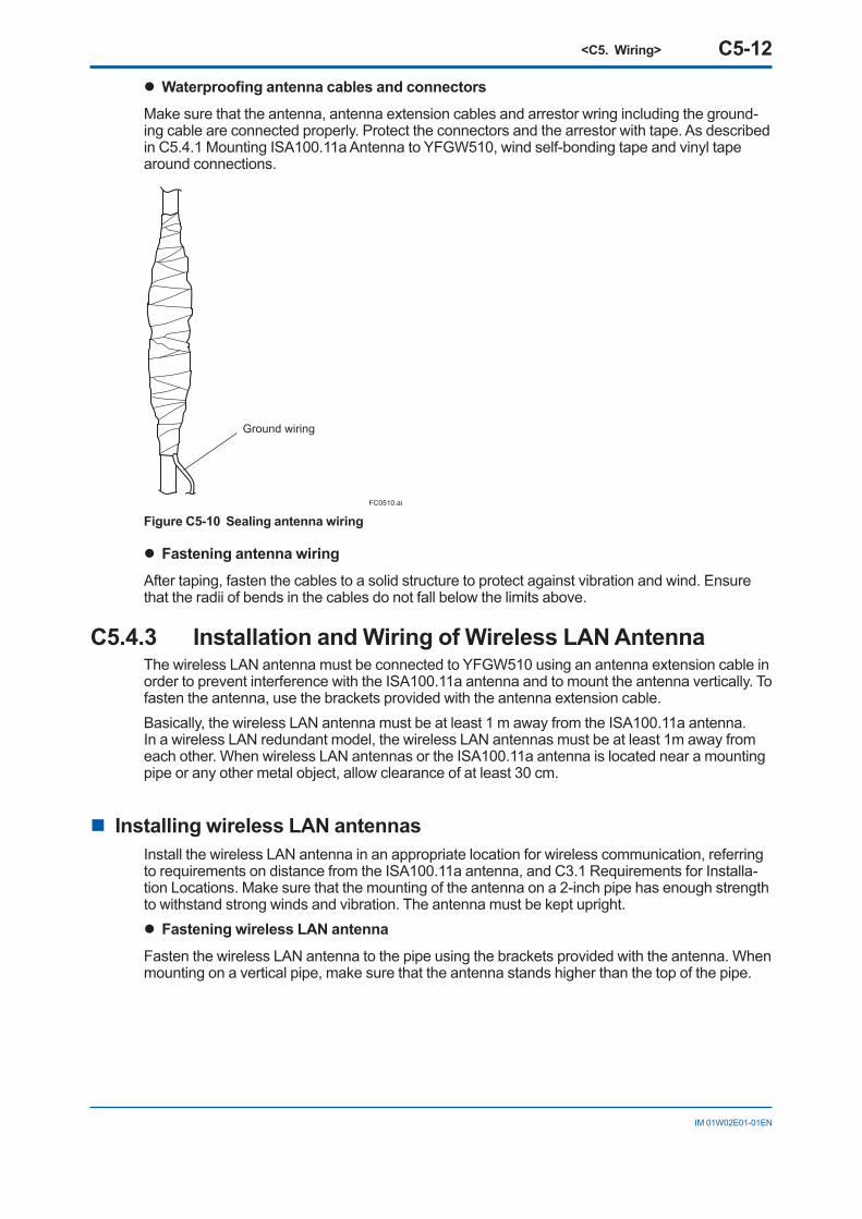
l Waterproofing antenna cables and connectors
Make sure that the antenna, antenna extension cables and arrestor wring including the ground-ing cable are connected properly. Protect the connectors and the arrestor with tape. As described in C5.4.1 Mounting ISA100.11a Antenna to YFGW510, wind self-bonding tape and vinyl tape around connections.
Ground wiring
FC0510.ai
Figure C5-10 Sealing antenna wiring
l Fastening antenna wiring
After taping, fasten the cables to a solid structure to protect against vibration and wind. Ensure that the radii of bends in the cables do not fall below the limits above.
C5.4.3 Installation and Wiring of Wireless LAN AntennaThe wireless LAN antenna must be connected to YFGW510 using an antenna extension cable in order to prevent interference with the ISA100.11a antenna and to mount the antenna vertically. To fasten the antenna, use the brackets provided with the antenna extension cable.Basically, the wireless LAN antenna must be at least 1 m away from the ISA100.11a antenna. In a wireless LAN redundant model, the wireless LAN antennas must be at least 1m away from each other. When wireless LAN antennas or the ISA100.11a antenna is located near a mounting pipe or any other metal object, allow clearance of at least 30 cm.
n Installing wireless LAN antennasInstall the wireless LAN antenna in an appropriate location for wireless communication, referring to requirements on distance from the ISA100.11a antenna, and C3.1 Requirements for Installa-tion Locations. Make sure that the mounting of the antenna on a 2-inch pipe has enough strength to withstand strong winds and vibration. The antenna must be kept upright. l Fastening wireless LAN antenna
Fasten the wireless LAN antenna to the pipe using the brackets provided with the antenna. When mounting on a vertical pipe, make sure that the antenna stands higher than the top of the pipe.
<C5. Wiring> C5-13
IM 01W02E01-01EN
FC0511-1.aiAntenna Extension Cable Bracket
Vertical piping
U BoltNut
Nut
FC0511-2.ai
Wireless LAN antenna
FC0511-3.ai
Bracket
Horizontal piping
U Bolt
FC0511-4.ai
Wireless LAN antenna
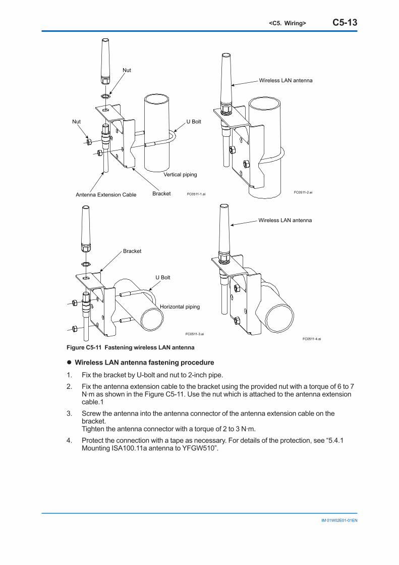
Figure C5-11 Fastening wireless LAN antenna
l Wireless LAN antenna fastening procedure
1. Fix the bracket by U-bolt and nut to 2-inch pipe.2. Fix the antenna extension cable to the bracket using the provided nut with a torque of 6 to 7
N∙m as shown in the Figure C5-11. Use the nut which is attached to the antenna extension cable.1
3. Screw the antenna into the antenna connector of the antenna extension cable on the bracket. Tighten the antenna connector with a torque of 2 to 3 N∙m.
4. Protect the connection with a tape as necessary. For details of the protection, see “5.4.1 Mounting ISA100.11a antenna to YFGW510”.
<C5. Wiring> C5-14
IM 01W02E01-01EN
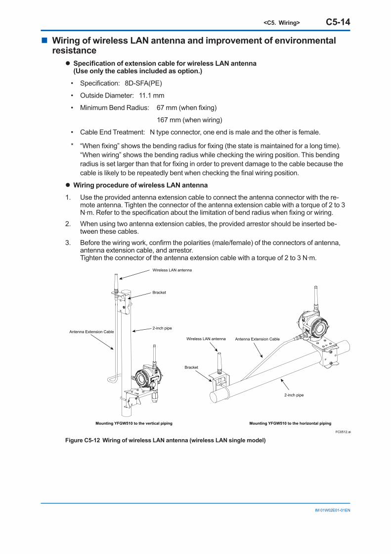
n Wiring of wireless LAN antenna and improvement of environmental resistance
l Specification of extension cable for wireless LAN antenna(Use only the cables included as option.)
• Specification: 8D-SFA(PE)
• Outside Diameter: 11.1 mm
• Minimum Bend Radius: 67 mm (when fixing)
167 mm (when wiring)
• Cable End Treatment: N type connector, one end is male and the other is female.
* “When fixing” shows the bending radius for fixing (the state is maintained for a long time). “When wiring” shows the bending radius while checking the wiring position. This bending
radius is set larger than that for fixing in order to prevent damage to the cable because the cable is likely to be repeatedly bent when checking the final wiring position.
l Wiring procedure of wireless LAN antenna
1. Use the provided antenna extension cable to connect the antenna connector with the re-mote antenna. Tighten the connector of the antenna extension cable with a torque of 2 to 3 N∙m. Refer to the specification about the limitation of bend radius when fixing or wiring.
2. When using two antenna extension cables, the provided arrestor should be inserted be-tween these cables.
3. Before the wiring work, confirm the polarities (male/female) of the connectors of antenna, antenna extension cable, and arrestor. Tighten the connector of the antenna extension cable with a torque of 2 to 3 N∙m.
FC0512.ai
Wireless LAN antenna
Wireless LAN antenna
Antenna Extension Cable
Antenna Extension Cable
Bracket
Bracket
Mounting YFGW510 to the vertical piping Mounting YFGW510 to the horizontal piping
2-inch pipe
2-inch pipe
Figure C5-12 Wiring of wireless LAN antenna (wireless LAN single model)
<C5. Wiring> C5-15
IM 01W02E01-01EN
FC0513.ai
Wireless LAN antenna
Wireless LAN antenna
Wireless LAN antenna
Wireless LAN antenna
Antenna Extension Cable
Antenna Extension CableAntenna Extension Cable
Antenna Extension Cable
Bracket
Bracket
Bracket
Bracket
Mounting YFGW510 to the vertical piping Mounting YFGW510 to the horizontal piping
2-inch pipe2-inch pipe
2-inch pipe
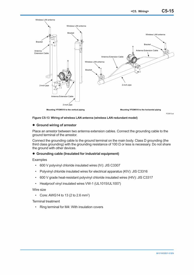
Figure C5-13 Wiring of wireless LAN antenna (wireless LAN redundant model)
l Ground wiring of arrestor
Place an arrestor between two antenna extension cables. Connect the grounding cable to the ground terminal of the arrestor.Connect the grounding cable to the ground terminal on the main body. Class D grounding (the third class grounding) with the grounding resistance of 100 Ω or less is necessary. Do not share the ground with other devices. l Grounding cable (Insulated for industrial equipment)
Examples• 600 V polyvinyl chloride insulated wires (IV): JIS C3307
• Polyvinyl chloride insulated wires for electrical apparatus (KIV): JIS C3316
• 600 V grade heat-resistant polyvinyl chloride insulated wires (HIV): JIS C3317
• Heatproof vinyl insulated wires VW-1 (UL1015/UL1007)
Wire size• Core: AWG14 to 13 (2 to 2.6 mm2)
Terminal treatment• Ring terminal for M4: With insulation covers
<C5. Wiring> C5-16
IM 01W02E01-01EN
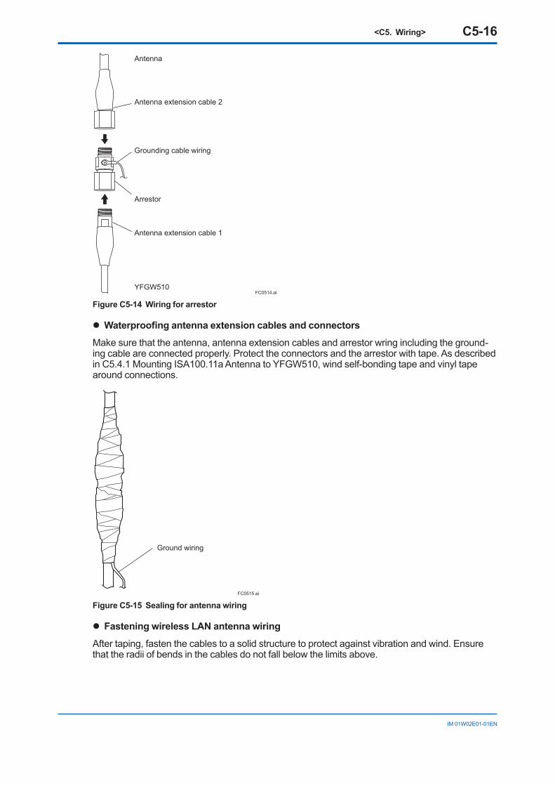
FC0514.ai
Antenna
YFGW510
Antenna extension cable 2
Grounding cable wiring
Arrestor
Antenna extension cable 1
Figure C5-14 Wiring for arrestor
l Waterproofing antenna extension cables and connectors
Make sure that the antenna, antenna extension cables and arrestor wring including the ground-ing cable are connected properly. Protect the connectors and the arrestor with tape. As described in C5.4.1 Mounting ISA100.11a Antenna to YFGW510, wind self-bonding tape and vinyl tape around connections.
Ground wiring
FC0515.ai
Figure C5-15 Sealing for antenna wiring
l Fastening wireless LAN antenna wiring
After taping, fasten the cables to a solid structure to protect against vibration and wind. Ensure that the radii of bends in the cables do not fall below the limits above.

<C6. Explosion Proof Wiring> C6-1
IM 01W02E01-01EN
C6. Explosion Proof WiringBe sure to read the precautions for the explosion protected type product including wiring described in “YFGW510 Field Wireless Access Point Read Me First (IM 01W02E01-11EN)”.Remainder of page intentionally left blank
<D1. Initial Configuration> D1-1
IM 01W02E01-01EN
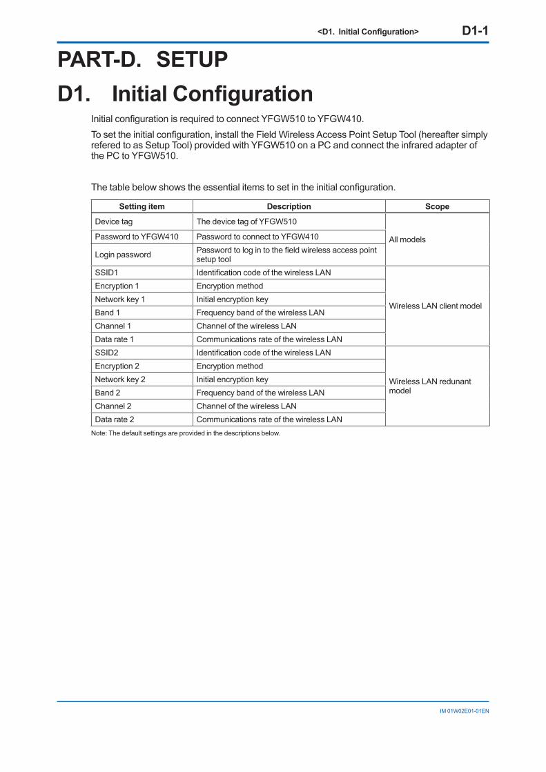
PART-D. SETUPD1. Initial Configuration
Initial configuration is required to connect YFGW510 to YFGW410.To set the initial configuration, install the Field Wireless Access Point Setup Tool (hereafter simply refered to as Setup Tool) provided with YFGW510 on a PC and connect the infrared adapter of the PC to YFGW510.
The table below shows the essential items to set in the initial configuration.
Setting item Description Scope
Device tag The device tag of YFGW510
All modelsPassword to YFGW410 Password to connect to YFGW410
Login password Password to log in to the field wireless access point setup tool
SSID1 Identification code of the wireless LAN
Wireless LAN client model
Encryption 1 Encryption methodNetwork key 1 Initial encryption keyBand 1 Frequency band of the wireless LANChannel 1 Channel of the wireless LANData rate 1 Communications rate of the wireless LANSSID2 Identification code of the wireless LAN
Wireless LAN redunant model
Encryption 2 Encryption methodNetwork key 2 Initial encryption keyBand 2 Frequency band of the wireless LANChannel 2 Channel of the wireless LANData rate 2 Communications rate of the wireless LAN
Note: The default settings are provided in the descriptions below.
<D2. Setup Tool> D2-1
IM 01W02E01-01EN
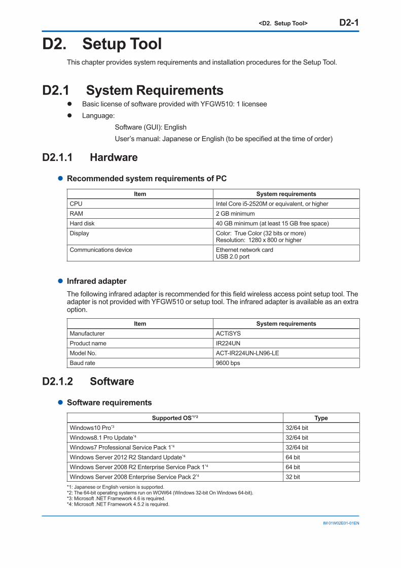
D2. Setup ToolThis chapter provides system requirements and installation procedures for the Setup Tool.
D2.1 System Requirementsl Basic license of software provided with YFGW510: 1 licenseel Language: Software (GUI): English User’s manual: Japanese or English (to be specified at the time of order)
D2.1.1 Hardware
l Recommended system requirements of PC
Item System requirementsCPU Intel Core i5-2520M or equivalent, or higherRAM 2 GB minimumHard disk 40 GB minimum (at least 15 GB free space)Display Color: True Color (32 bits or more)
Resolution: 1280 x 800 or higherCommunications device Ethernet network card
USB 2.0 port
l Infrared adapterThe following infrared adapter is recommended for this field wireless access point setup tool. The adapter is not provided with YFGW510 or setup tool. The infrared adapter is available as an extra option.
Item System requirementsManufacturer ACTiSYSProduct name IR224UNModel No. ACT-IR224UN-LN96-LEBaud rate 9600 bps
D2.1.2 Software
l Software requirements
Supported OS*1*2 TypeWindows10 Pro*3 32/64 bitWindows8.1 Pro Update*4 32/64 bitWindows7 Professional Service Pack 1*4 32/64 bitWindows Server 2012 R2 Standard Update*4 64 bitWindows Server 2008 R2 Enterprise Service Pack 1*4 64 bitWindows Server 2008 Enterprise Service Pack 2*4 32 bit
*1: Japanese or English version is supported.*2: The 64-bit operating systems run on WOW64 (Windows 32-bit On Windows 64-bit).*3: Microsoft .NET Framework 4.6 is required.*4: Microsoft .NET Framework 4.5.2 is required.
<D2. Setup Tool> D2-2
IM 01W02E01-01EN
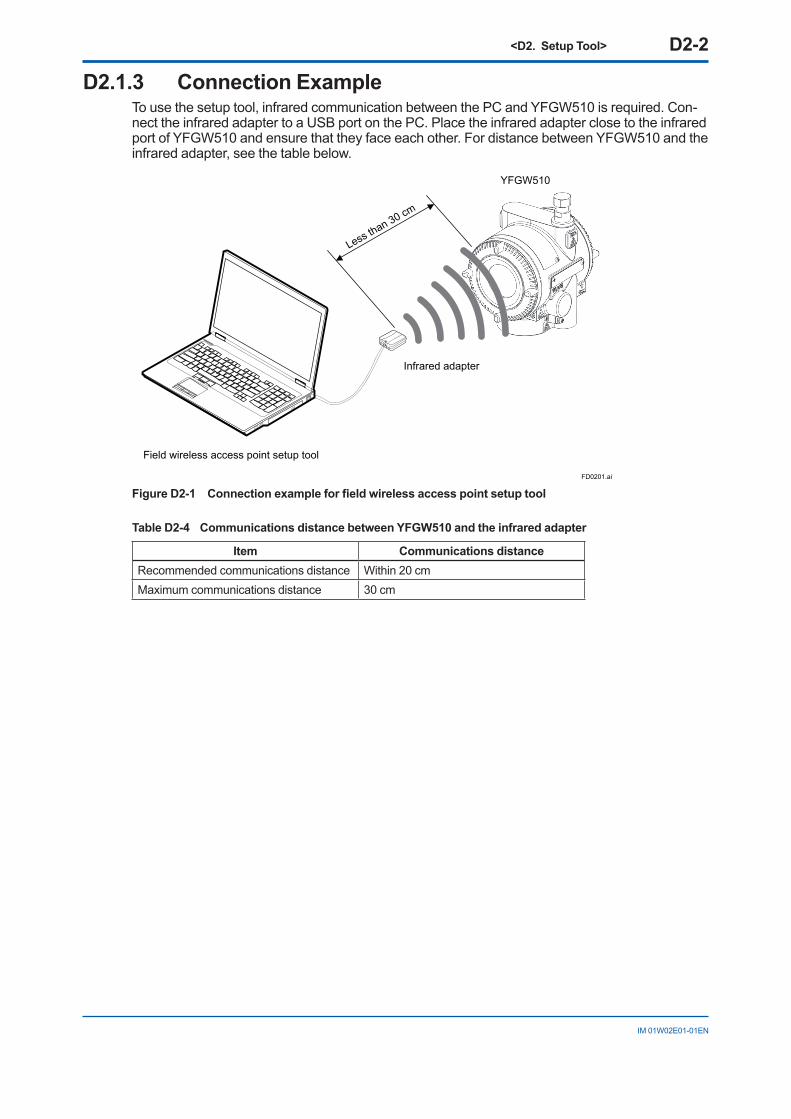
D2.1.3 Connection ExampleTo use the setup tool, infrared communication between the PC and YFGW510 is required. Con-nect the infrared adapter to a USB port on the PC. Place the infrared adapter close to the infrared port of YFGW510 and ensure that they face each other. For distance between YFGW510 and the infrared adapter, see the table below.
FD0201.ai
Less than 30 cm
Infrared adapter
YFGW510
Field wireless access point setup tool
Figure D2-1 Connection example for field wireless access point setup tool
Table D2-4 Communications distance between YFGW510 and the infrared adapter
Item Communications distanceRecommended communications distance Within 20 cmMaximum communications distance 30 cm
<D2. Setup Tool> D2-3
IM 01W02E01-01EN
D2.2 Installation ProcedureInstall the Setup Tool and an infrared adapter driver on the PC.
D2.2.1 Driver for Infrared Adapter
l Installing the driverInstall the driver by the media provided with the infrared adapter, referring to the user’s manual of ACTiSYS
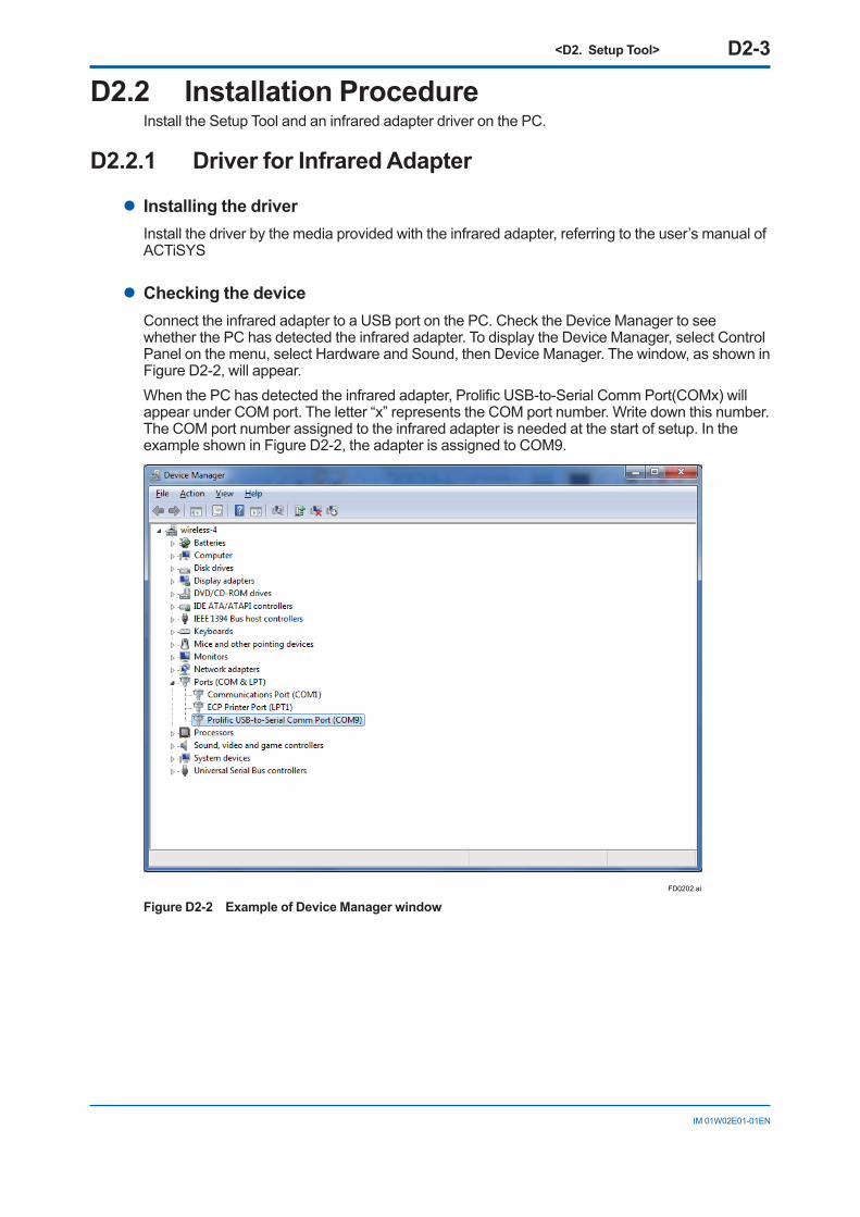
l Checking the deviceConnect the infrared adapter to a USB port on the PC. Check the Device Manager to see whether the PC has detected the infrared adapter. To display the Device Manager, select Control Panel on the menu, select Hardware and Sound, then Device Manager. The window, as shown in Figure D2-2, will appear.When the PC has detected the infrared adapter, Prolific USB-to-Serial Comm Port(COMx) will appear under COM port. The letter “x” represents the COM port number. Write down this number. The COM port number assigned to the infrared adapter is needed at the start of setup. In the example shown in Figure D2-2, the adapter is assigned to COM9.
FD0202.ai
Figure D2-2 Example of Device Manager window
<D2. Setup Tool> D2-4
IM 01W02E01-01EN
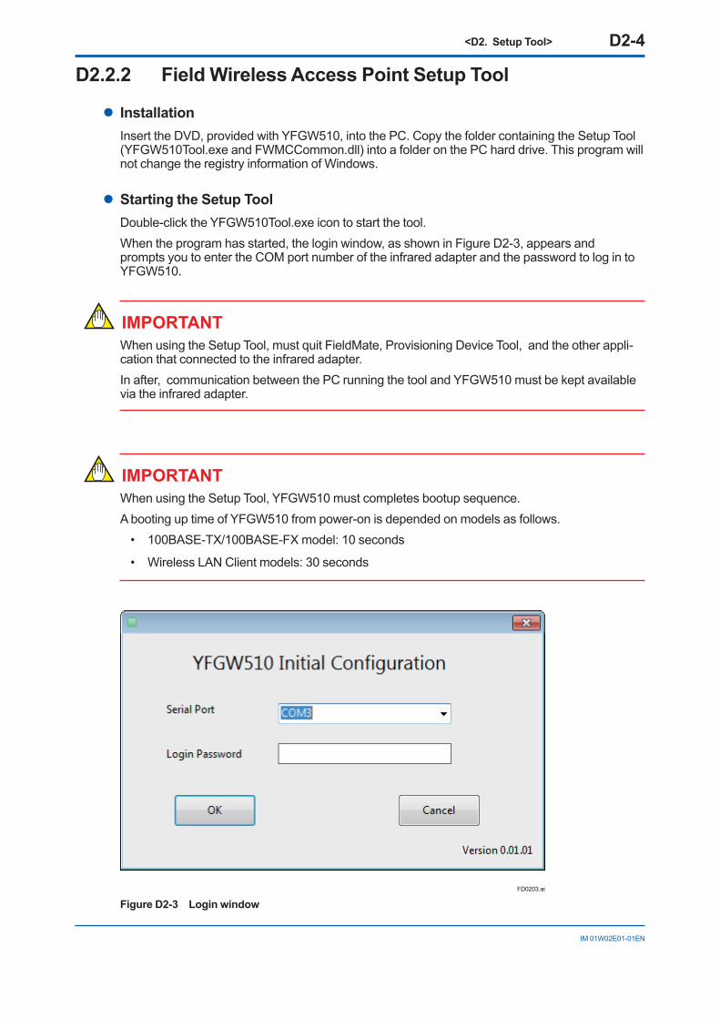
D2.2.2 Field Wireless Access Point Setup Tool
l InstallationInsert the DVD, provided with YFGW510, into the PC. Copy the folder containing the Setup Tool (YFGW510Tool.exe and FWMCCommon.dll) into a folder on the PC hard drive. This program will not change the registry information of Windows.
l Starting the Setup ToolDouble-click the YFGW510Tool.exe icon to start the tool.When the program has started, the login window, as shown in Figure D2-3, appears and prompts you to enter the COM port number of the infrared adapter and the password to log in to YFGW510.
IMPORTANTWhen using the Setup Tool, must quit FieldMate, Provisioning Device Tool, and the other appli-cation that connected to the infrared adapter. In after, communication between the PC running the tool and YFGW510 must be kept available via the infrared adapter.
IMPORTANTWhen using the Setup Tool, YFGW510 must completes bootup sequence.A booting up time of YFGW510 from power-on is depended on models as follows.
• 100BASE-TX/100BASE-FX model: 10 seconds
• Wireless LAN Client models: 30 seconds
FD0203.ai
Figure D2-3 Login window
<D2. Setup Tool> D2-5
IM 01W02E01-01EN
The table below shows the setting items and their default settings.
Item Number of characters Default setting
Serial Port The number of the port the infra-red adapter is connected to
The smallest COM number among those devices
Login PasswordUp to 8 one-byte alphanumeric characters or other symbols (e.g., !,$,#)
yokogawa
In the Serial Port field, enter the COM port number of the infrared adapter. Open the pull-down list, then select the COM port number to which the infrared adapter is connected.When beginning the program for the first time, enter the default login password in the Login Pass-word field.Click the [OK] button. The Change Login Password window as shown in Figure D2-5 will appear if the Setup Tool is communicating with YFGW510.Click the [Cancel] button to exit the setup tool. The window will close.
IMPORTANT• If the wrong password is entered three times straight, YFGW510 will not accept another
login attempt for 30 minutes. Type in the password carefully.
• Keep the login password safe. It is necessary for setting up the YFGW510.
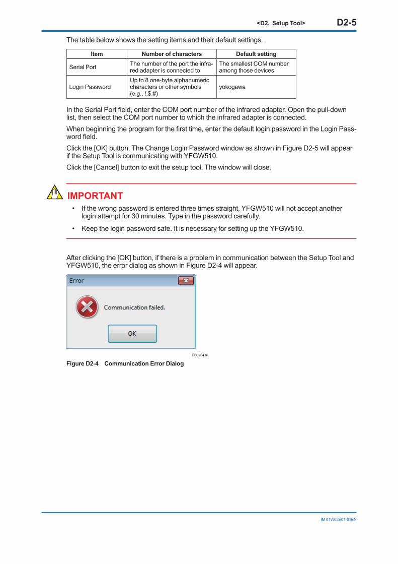
After clicking the [OK] button, if there is a problem in communication between the Setup Tool and YFGW510, the error dialog as shown in Figure D2-4 will appear.
FD0204.ai
Figure D2-4 Communication Error Dialog
<D2. Setup Tool> D2-6
IM 01W02E01-01EN
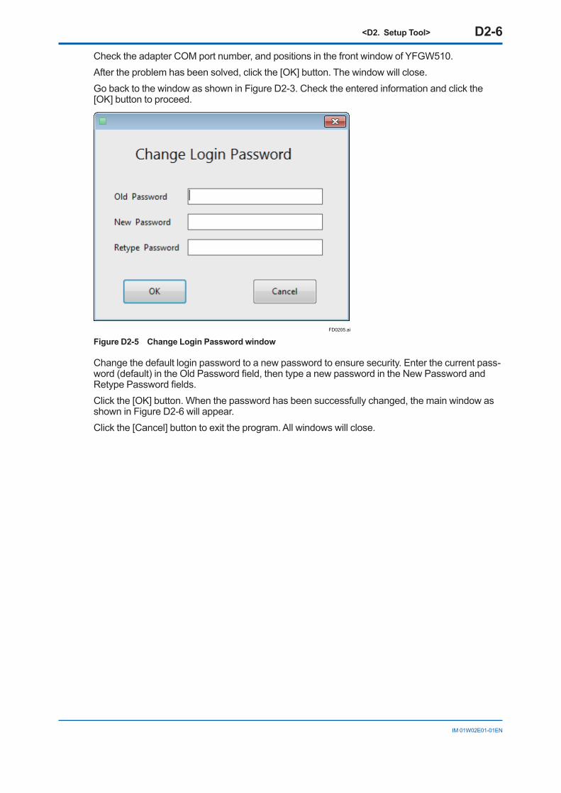
Check the adapter COM port number, and positions in the front window of YFGW510.After the problem has been solved, click the [OK] button. The window will close.Go back to the window as shown in Figure D2-3. Check the entered information and click the [OK] button to proceed.
FD0205.ai
Figure D2-5 Change Login Password window
Change the default login password to a new password to ensure security. Enter the current pass-word (default) in the Old Password field, then type a new password in the New Password and Retype Password fields.Click the [OK] button. When the password has been successfully changed, the main window as shown in Figure D2-6 will appear.Click the [Cancel] button to exit the program. All windows will close.
<D2. Setup Tool> D2-7
IM 01W02E01-01EN
FD0206.ai
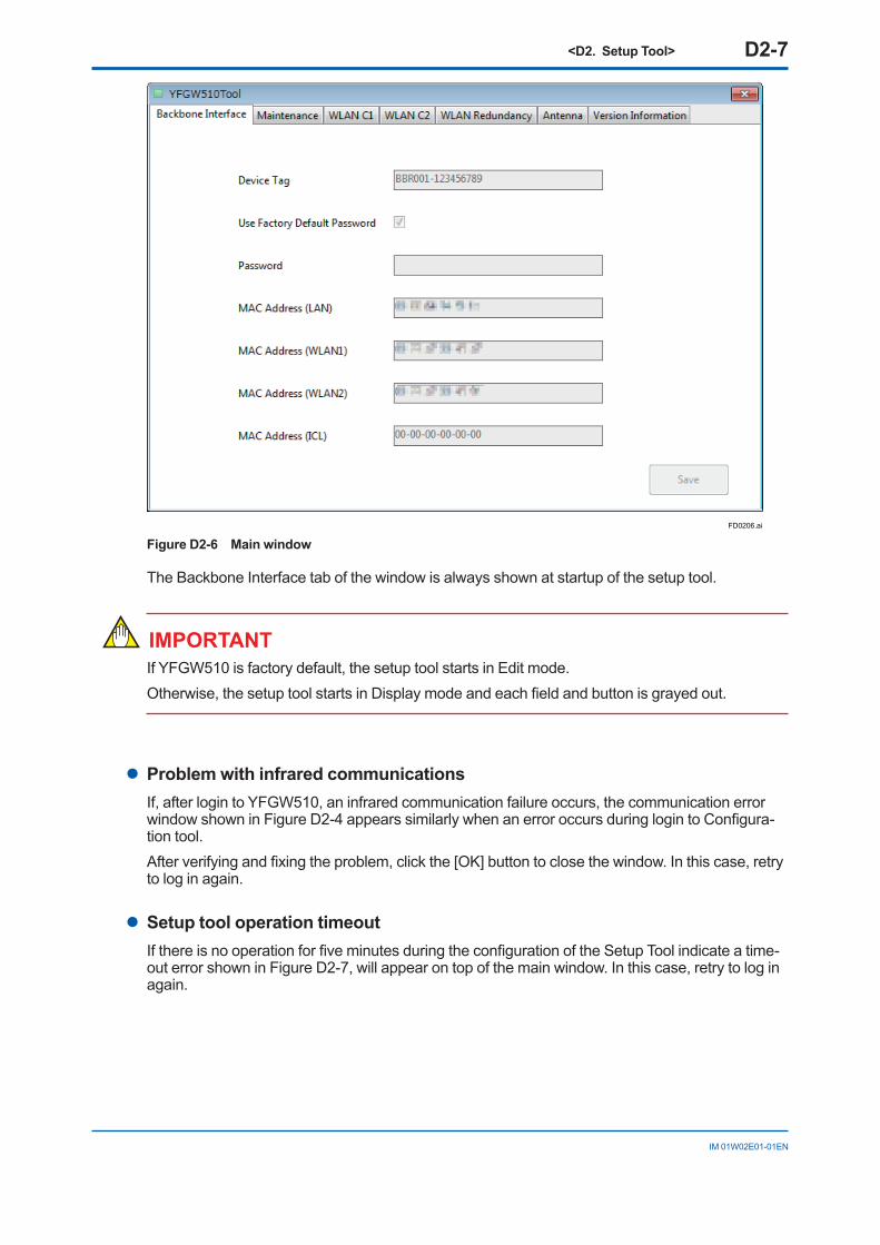
Figure D2-6 Main window
The Backbone Interface tab of the window is always shown at startup of the setup tool.
IMPORTANTIf YFGW510 is factory default, the setup tool starts in Edit mode.Otherwise, the setup tool starts in Display mode and each field and button is grayed out.
l Problem with infrared communicationsIf, after login to YFGW510, an infrared communication failure occurs, the communication error window shown in Figure D2-4 appears similarly when an error occurs during login to Configura-tion tool. After verifying and fixing the problem, click the [OK] button to close the window. In this case, retry to log in again.
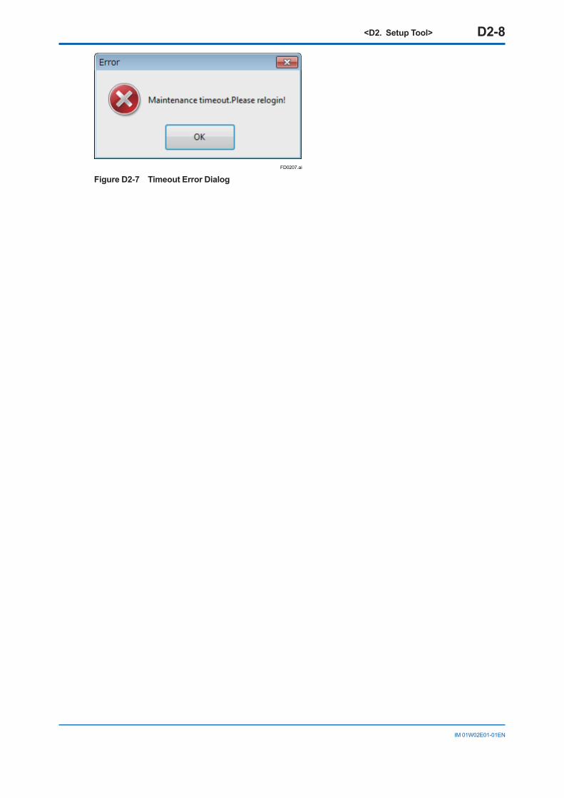
l Setup tool operation timeoutIf there is no operation for five minutes during the configuration of the Setup Tool indicate a time-out error shown in Figure D2-7, will appear on top of the main window. In this case, retry to log in again.
<D2. Setup Tool> D2-8
IM 01W02E01-01EN
FD0207.ai
Figure D2-7 Timeout Error Dialog
<D3. Configuration Method> D3-1
IM 01W02E01-01EN
D3. Configuration MethodThis chapter describes initial configuration of YFGW510 using the Setup Tool.
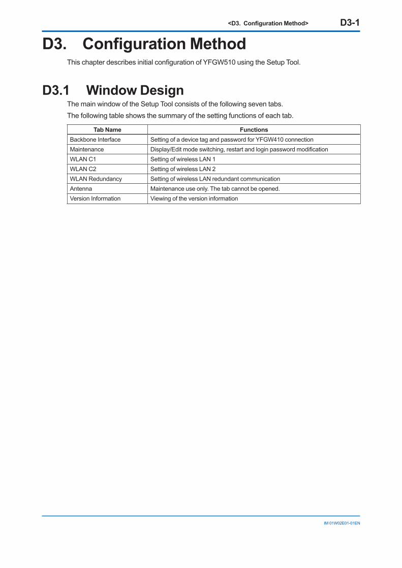
D3.1 Window DesignThe main window of the Setup Tool consists of the following seven tabs.The following table shows the summary of the setting functions of each tab.
Tab Name FunctionsBackbone Interface Setting of a device tag and password for YFGW410 connectionMaintenance Display/Edit mode switching, restart and login password modificationWLAN C1 Setting of wireless LAN 1WLAN C2 Setting of wireless LAN 2WLAN Redundancy Setting of wireless LAN redundant communicationAntenna Maintenance use only. The tab cannot be opened.Version Information Viewing of the version information
<D3. Configuration Method> D3-2
IM 01W02E01-01EN
D3.2 Display/Edit Mode SwitchingThe Setup Tool has two operation modes: Display, to view the setting information, and Edit, to configure YFGW510. The Setup Tool always starts up in Display mode. To allow for YFGW510 configuration, the mode needs to be switched to Edit.
IMPORTANTIf YFGW510 is factory default, the setup tool starts in Edit mode.Otherwise, the setup tool starts in Display mode and each field and button is grayed out.
IMPORTANTIf switching Display/Edit Mode, YFGW510 will restart.
IMPORTANTIn Edit mode, only infrared communication is available.
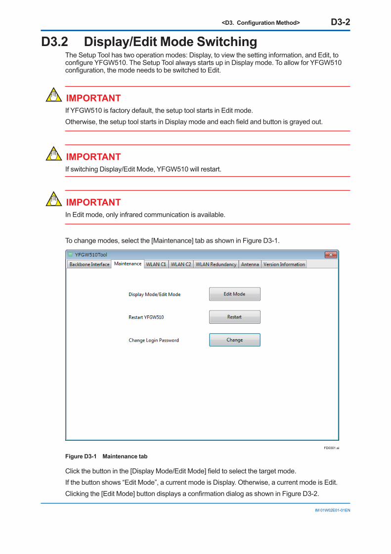
To change modes, select the [Maintenance] tab as shown in Figure D3-1.
FD0301.ai
Figure D3-1 Maintenance tab
Click the button in the [Display Mode/Edit Mode] field to select the target mode.If the button shows “Edit Mode”, a current mode is Display. Otherwise, a current mode is Edit.Clicking the [Edit Mode] button displays a confirmation dialog as shown in Figure D3-2.
<D3. Configuration Method> D3-3
IM 01W02E01-01EN
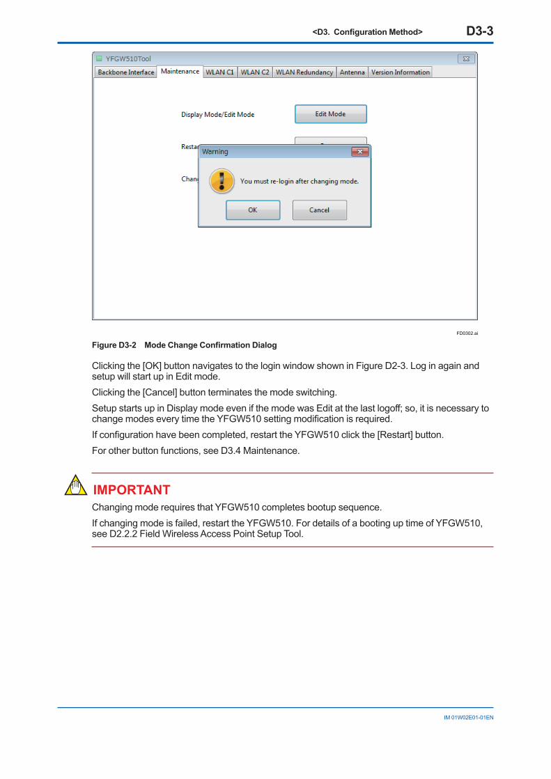
FD0302.ai
Figure D3-2 Mode Change Confirmation Dialog
Clicking the [OK] button navigates to the login window shown in Figure D2-3. Log in again and setup will start up in Edit mode.Clicking the [Cancel] button terminates the mode switching.Setup starts up in Display mode even if the mode was Edit at the last logoff; so, it is necessary to change modes every time the YFGW510 setting modification is required.If configuration have been completed, restart the YFGW510 click the [Restart] button.For other button functions, see D3.4 Maintenance.
IMPORTANTChanging mode requires that YFGW510 completes bootup sequence.If changing mode is failed, restart the YFGW510. For details of a booting up time of YFGW510, see D2.2.2 Field Wireless Access Point Setup Tool.
<D3. Configuration Method> D3-4
IM 01W02E01-01EN
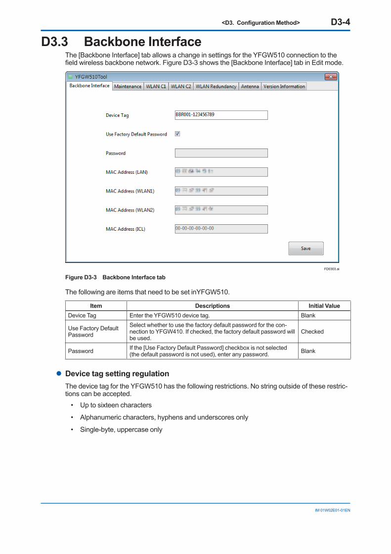
D3.3 Backbone InterfaceThe [Backbone Interface] tab allows a change in settings for the YFGW510 connection to the field wireless backbone network. Figure D3-3 shows the [Backbone Interface] tab in Edit mode.
FD0303.ai
Figure D3-3 Backbone Interface tab
The following are items that need to be set inYFGW510.
Item Descriptions Initial ValueDevice Tag Enter the YFGW510 device tag. Blank
Use Factory Default Password
Select whether to use the factory default password for the con-nection to YFGW410. If checked, the factory default password will be used.
Checked
Password If the [Use Factory Default Password] checkbox is not selected (the default password is not used), enter any password. Blank
l Device tag setting regulationThe device tag for the YFGW510 has the following restrictions. No string outside of these restric-tions can be accepted.
• Up to sixteen characters
• Alphanumeric characters, hyphens and underscores only
• Single-byte, uppercase only
<D3. Configuration Method> D3-5
IM 01W02E01-01EN
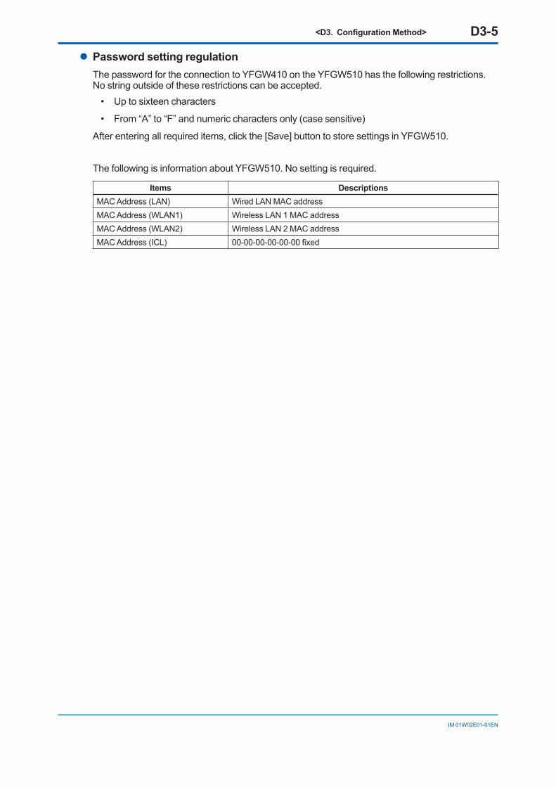
l Password setting regulationThe password for the connection to YFGW410 on the YFGW510 has the following restrictions. No string outside of these restrictions can be accepted.
• Up to sixteen characters
• From “A” to “F” and numeric characters only (case sensitive)
After entering all required items, click the [Save] button to store settings in YFGW510.
The following is information about YFGW510. No setting is required.
Items DescriptionsMAC Address (LAN) Wired LAN MAC addressMAC Address (WLAN1) Wireless LAN 1 MAC addressMAC Address (WLAN2) Wireless LAN 2 MAC addressMAC Address (ICL) 00-00-00-00-00-00 fixed
<D3. Configuration Method> D3-6
IM 01W02E01-01EN
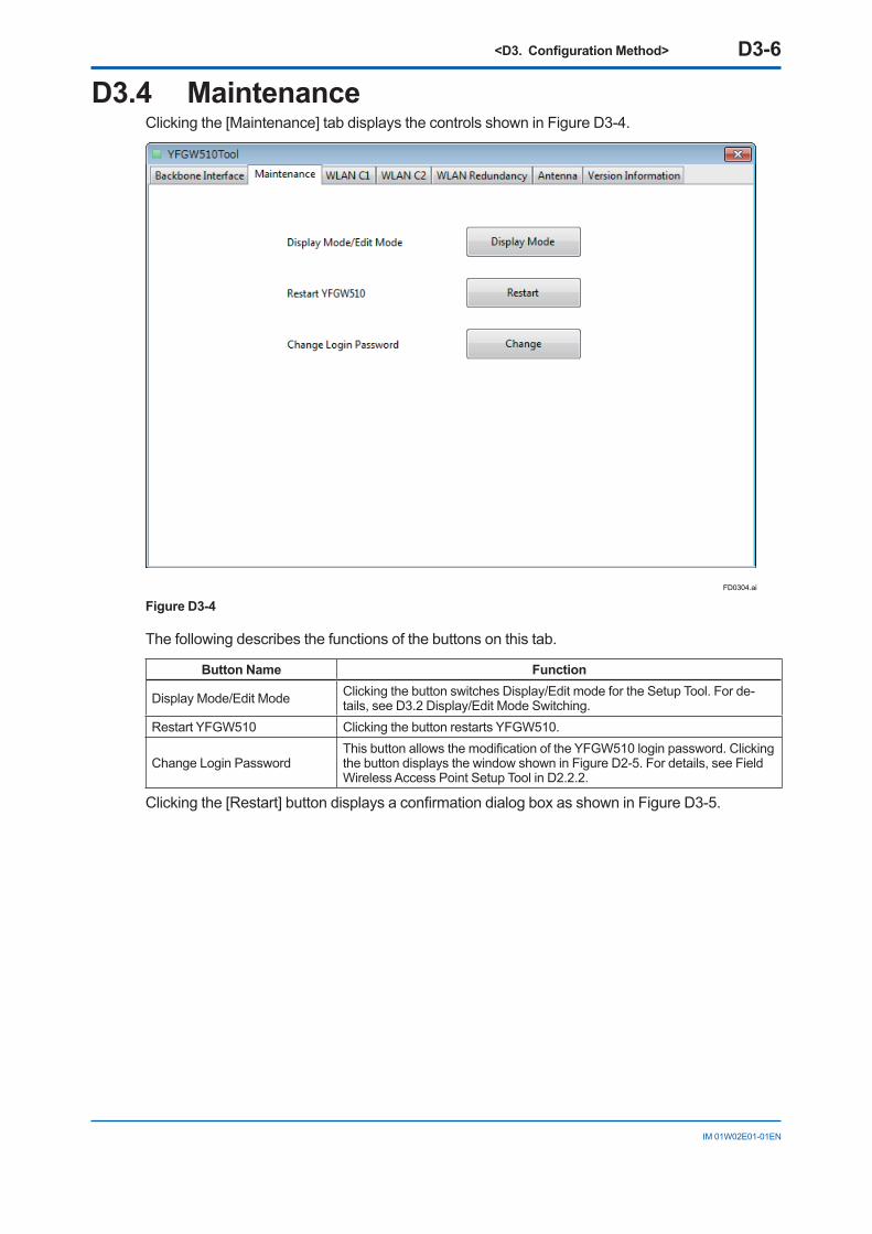
D3.4 MaintenanceClicking the [Maintenance] tab displays the controls shown in Figure D3-4.
FD0304.ai
Figure D3-4
The following describes the functions of the buttons on this tab.
Button Name Function
Display Mode/Edit Mode Clicking the button switches Display/Edit mode for the Setup Tool. For de-tails, see D3.2 Display/Edit Mode Switching.
Restart YFGW510 Clicking the button restarts YFGW510.
Change Login PasswordThis button allows the modification of the YFGW510 login password. Clicking the button displays the window shown in Figure D2-5. For details, see Field Wireless Access Point Setup Tool in D2.2.2.
Clicking the [Restart] button displays a confirmation dialog box as shown in Figure D3-5.
<D3. Configuration Method> D3-7
IM 01W02E01-01EN
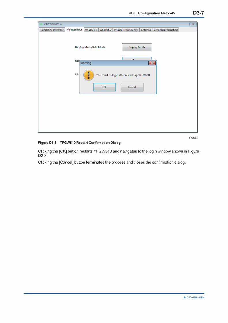
FD0305.ai
Figure D3-5 YFGW510 Restart Confirmation Dialog
Clicking the [OK] button restarts YFGW510 and navigates to the login window shown in Figure D2-3.Clicking the [Cancel] button terminates the process and closes the confirmation dialog.
<D3. Configuration Method> D3-8
IM 01W02E01-01EN
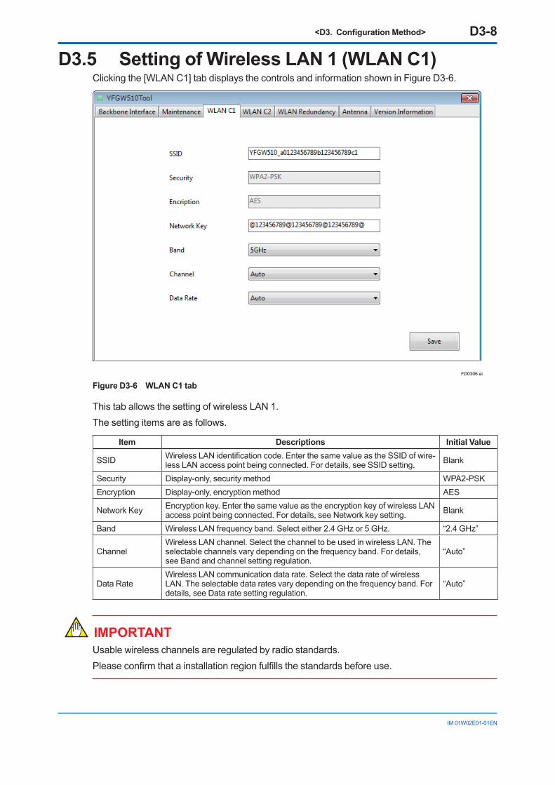
D3.5 Setting of Wireless LAN 1 (WLAN C1)Clicking the [WLAN C1] tab displays the controls and information shown in Figure D3-6.
FD0306.ai
Figure D3-6 WLAN C1 tab
This tab allows the setting of wireless LAN 1.The setting items are as follows.
Item Descriptions Initial Value
SSID Wireless LAN identification code. Enter the same value as the SSID of wire-less LAN access point being connected. For details, see SSID setting. Blank
Security Display-only, security method WPA2-PSKEncryption Display-only, encryption method AES
Network Key Encryption key. Enter the same value as the encryption key of wireless LAN access point being connected. For details, see Network key setting. Blank
Band Wireless LAN frequency band. Select either 2.4 GHz or 5 GHz. “2.4 GHz”
ChannelWireless LAN channel. Select the channel to be used in wireless LAN. The selectable channels vary depending on the frequency band. For details, see Band and channel setting regulation.
“Auto”
Data RateWireless LAN communication data rate. Select the data rate of wireless LAN. The selectable data rates vary depending on the frequency band. For details, see Data rate setting regulation.
“Auto”
IMPORTANTUsable wireless channels are regulated by radio standards.Please confirm that a installation region fulfills the standards before use.
<D3. Configuration Method> D3-9
IM 01W02E01-01EN
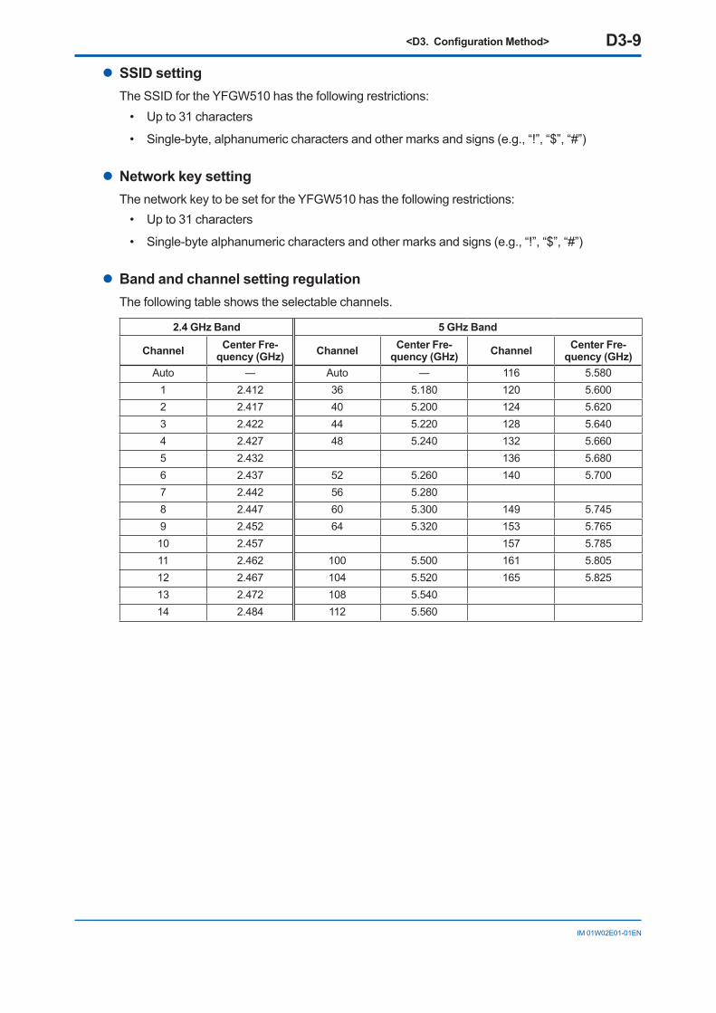
l SSID settingThe SSID for the YFGW510 has the following restrictions:
• Up to 31 characters
• Single-byte, alphanumeric characters and other marks and signs (e.g., “!”, “$”, “#”)
l Network key settingThe network key to be set for the YFGW510 has the following restrictions:
• Up to 31 characters
• Single-byte alphanumeric characters and other marks and signs (e.g., “!”, “$”, “#”)
l Band and channel setting regulationThe following table shows the selectable channels.
2.4 GHz Band 5 GHz Band
Channel Center Fre-quency (GHz) Channel Center Fre-
quency (GHz) Channel Center Fre-quency (GHz)
Auto ― Auto ― 116 5.5801 2.412 36 5.180 120 5.6002 2.417 40 5.200 124 5.6203 2.422 44 5.220 128 5.6404 2.427 48 5.240 132 5.6605 2.432 136 5.6806 2.437 52 5.260 140 5.7007 2.442 56 5.2808 2.447 60 5.300 149 5.7459 2.452 64 5.320 153 5.76510 2.457 157 5.78511 2.462 100 5.500 161 5.80512 2.467 104 5.520 165 5.82513 2.472 108 5.54014 2.484 112 5.560
<D3. Configuration Method> D3-10
IM 01W02E01-01EN
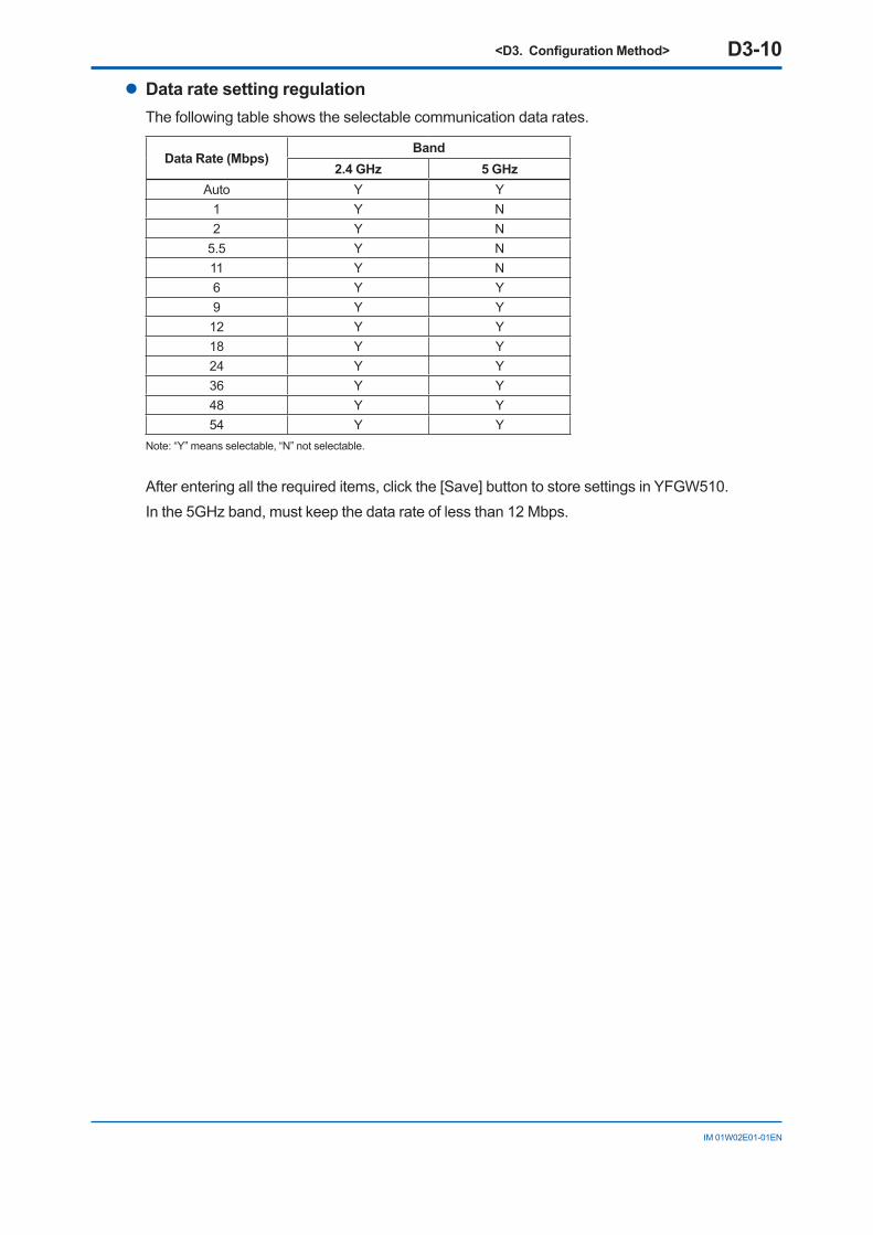
l Data rate setting regulationThe following table shows the selectable communication data rates.
Data Rate (Mbps)Band
2.4 GHz 5 GHzAuto Y Y
1 Y N2 Y N
5.5 Y N11 Y N6 Y Y9 Y Y12 Y Y18 Y Y24 Y Y36 Y Y48 Y Y54 Y Y
Note: “Y” means selectable, “N” not selectable.
After entering all the required items, click the [Save] button to store settings in YFGW510.In the 5GHz band, must keep the data rate of less than 12 Mbps.
<D3. Configuration Method> D3-11
IM 01W02E01-01EN
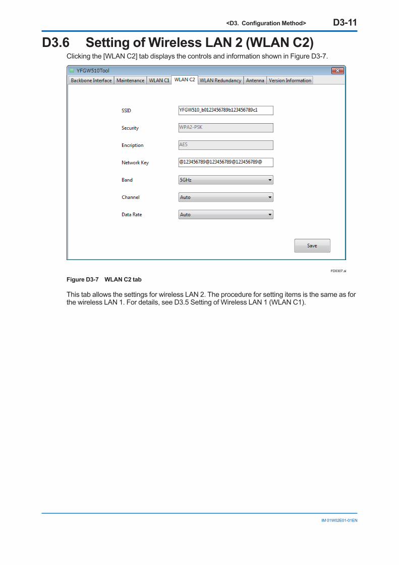
D3.6 Setting of Wireless LAN 2 (WLAN C2)Clicking the [WLAN C2] tab displays the controls and information shown in Figure D3-7.
FD0307.ai
Figure D3-7 WLAN C2 tab
This tab allows the settings for wireless LAN 2. The procedure for setting items is the same as for the wireless LAN 1. For details, see D3.5 Setting of Wireless LAN 1 (WLAN C1).
<D3. Configuration Method> D3-12
IM 01W02E01-01EN
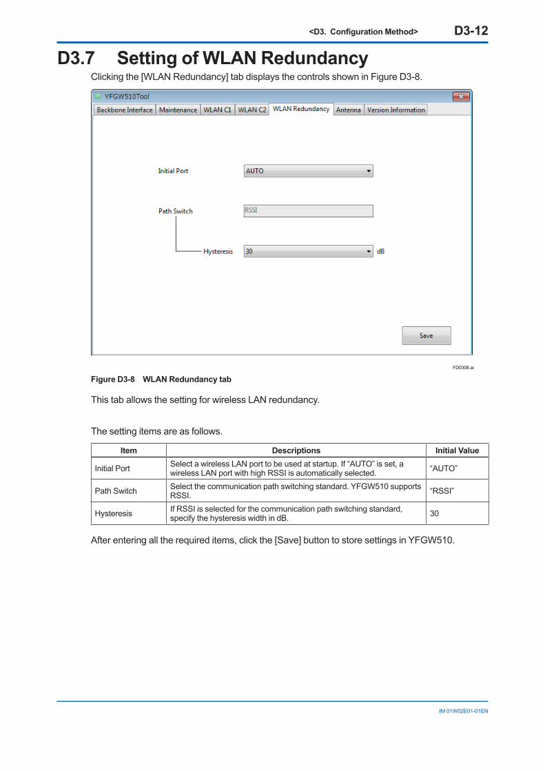
D3.7 Setting of WLAN RedundancyClicking the [WLAN Redundancy] tab displays the controls shown in Figure D3-8.
FD0308.ai
Figure D3-8 WLAN Redundancy tab
This tab allows the setting for wireless LAN redundancy.
The setting items are as follows.
Item Descriptions Initial Value
Initial Port Select a wireless LAN port to be used at startup. If “AUTO” is set, a wireless LAN port with high RSSI is automatically selected. “AUTO”
Path Switch Select the communication path switching standard. YFGW510 supports RSSI. “RSSI”
Hysteresis If RSSI is selected for the communication path switching standard, specify the hysteresis width in dB. 30
After entering all the required items, click the [Save] button to store settings in YFGW510.
<D3. Configuration Method> D3-13
IM 01W02E01-01EN
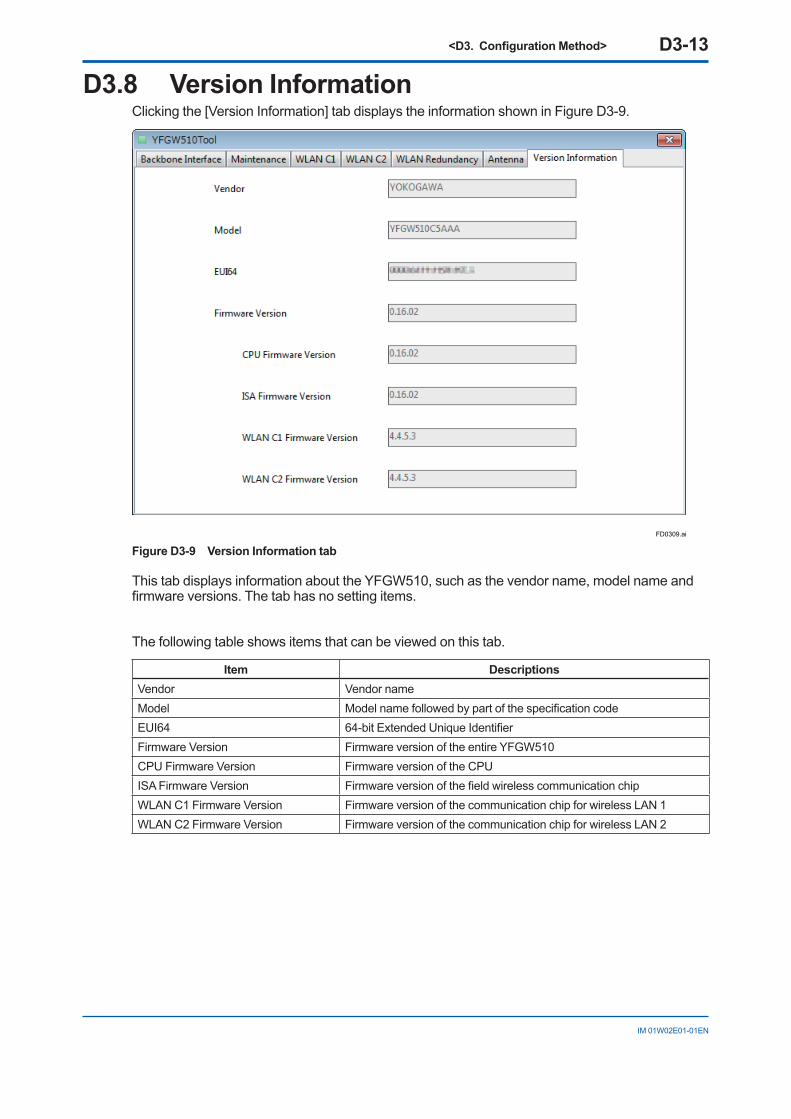
D3.8 Version InformationClicking the [Version Information] tab displays the information shown in Figure D3-9.
FD0309.ai
Figure D3-9 Version Information tab
This tab displays information about the YFGW510, such as the vendor name, model name and firmware versions. The tab has no setting items.
The following table shows items that can be viewed on this tab.
Item DescriptionsVendor Vendor nameModel Model name followed by part of the specification codeEUI64 64-bit Extended Unique IdentifierFirmware Version Firmware version of the entire YFGW510CPU Firmware Version Firmware version of the CPUISA Firmware Version Firmware version of the field wireless communication chipWLAN C1 Firmware Version Firmware version of the communication chip for wireless LAN 1WLAN C2 Firmware Version Firmware version of the communication chip for wireless LAN 2
<E1. Routine Maintenance> E1-1
IM 01W02E01-01EN
PART-E. OPERATION AND MAINTENANCE
For information about routine maintenance, or for YFGW510 additions or replacements, consult, in advance, the YFGW410 User’s Manual (IM 01W02D01-01EN).
E1. Routine MaintenanceFor problems during routine maintenance, check the host system monitoring YFG510, and the device information for the Monitor of the Field Wireless Management Console provided with the YFGW410. For details on the Monitor maintenance procedures and error prevention, see the YFGW410 User’s Manual (IM 01W02D01-01EN).During maintenance of YFGW510, check the installation and operation statuses of the main body as component to the field wireless system hardware.Confirm that the main body is correctly installed, free of dirt and that power and communication cables are securely connected. If the main body is dirty or dusty, wipe it out by using a soft cloth moistened with water or mild soap water.

<E2. Additions and Replacements> E2-1
IM 01W02E01-01EN
E2. Additions and ReplacementsFor instructions on adding or replacing YFGW510, see the YFGW410 User’s Manual (IM 01W02D01-01EN).

<E3. Maintenance in Hazardous Areas> E3-1
IM 01W02E01-01EN
E3. Maintenance in Hazardous Areas
IMPORTANTPlease be sure to read “YFGW510 Field Wireless Access Point Read Me First (IM 01W01E02-11EN)” for the precautions including maintenance and repair of the explosion protected type product.
In maintenance, check for loose power supply wiring, ground wiring or network cable connection.During maintenance and repair activities, if there is need to access the system in hazardous areas via an YFGW510 communication port, PCs and other devices used must comply with the explosion-proof requirements. For details, please contact Yokogawa Electric Corporation.
Explosion-proof instruments must retain their intended properties before and after maintenance. Otherwise, hazardous conditions can arise. Be sure to consult with Yokogawa Electric Corpora-tion for any repair and alteration.
For other field wireless system hardware components, see respective user’s manuals.
<E4. Components Having Defined Life Spans> E4-1
IM 01W02E01-01EN
E4. Components Having Defined Life Spans
YFGW510 includes no components having defined life spans that need replacing.For reference, the following are precautions for such components.
IMPORTANTPrecautions for components having defined life spans
• “Components having defined life spans” are those expected to wear out or break down within a 10-year period of use or in storage under normal conditions. Components designed for a life span of at least 10 years are excluded from the category.
• The “recommended replacement cycle” is the interval between preventive maintenance for components having defined life spans. It does not guarantee breakdown-free operation dur-ing that period.
• The recommended replacement cycle is a guideline. The actual replacement cycle may vary depending on the environmental conditions of use, such as ambient temperature.
• The recommended replacement cycle is subject to change according to performance in the field.
<F1. Status Information> F1-1
IM 01W02E01-01EN
PART-F. TROUBLESHOOTINGThis part describes troubleshooting for YFGW510. If any abnormalities are identified in YFGW510 through investigation and in accordance with procedures described in the YFGW410 User’s Manual (IM 01W02D01-01EN), check the following.
F1. Status InformationThe YFGW510 operational status information is shown in the backbone router status (BBR_STA-TUS) in the Modbus register.
The status data structure and the contents are as follows.
Modbus Address Name Data Format Contents
n Data status Unsigned 16 0x0080, fixed: normal
n + 1 Backbone router status
Unsigned 16 Backbone router status (0: connected/1: not connected)
n + 2 to n + 8 Unsigned 16 0, fixed (reserved bits)
Only the status having a Modbus address of (n + 1) is used. This indicates whether YFGW510 is connected to YFGW410 correctly.
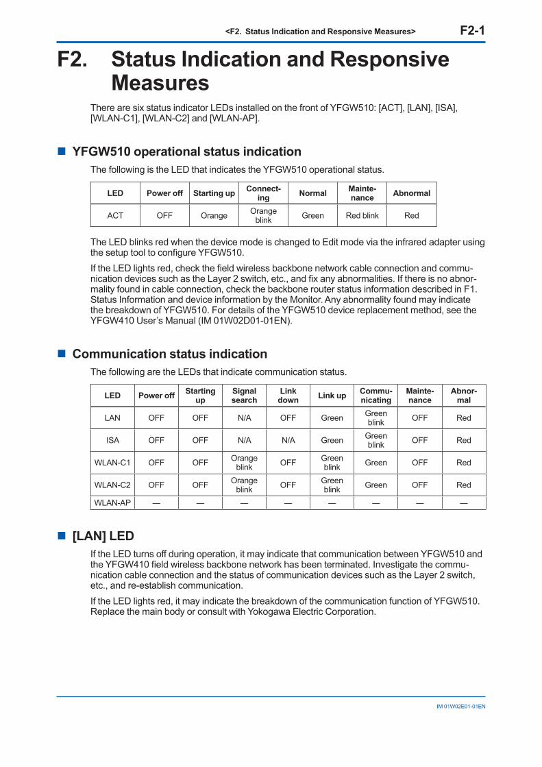
<F2. Status Indication and Responsive Measures> F2-1
IM 01W02E01-01EN
F2. Status Indication and Responsive Measures
There are six status indicator LEDs installed on the front of YFGW510: [ACT], [LAN], [ISA], [WLAN-C1], [WLAN-C2] and [WLAN-AP].
n YFGW510 operational status indicationThe following is the LED that indicates the YFGW510 operational status.
LED Power off Starting up Connect-ing Normal Mainte-
nance Abnormal
ACT OFF Orange Orange blink Green Red blink Red
The LED blinks red when the device mode is changed to Edit mode via the infrared adapter using the setup tool to configure YFGW510.If the LED lights red, check the field wireless backbone network cable connection and commu-nication devices such as the Layer 2 switch, etc., and fix any abnormalities. If there is no abnor-mality found in cable connection, check the backbone router status information described in F1. Status Information and device information by the Monitor. Any abnormality found may indicate the breakdown of YFGW510. For details of the YFGW510 device replacement method, see the YFGW410 User’s Manual (IM 01W02D01-01EN).
n Communication status indicationThe following are the LEDs that indicate communication status.
LED Power off Starting up
Signal search
Link down Link up Commu-
nicatingMainte-nance
Abnor-mal
LAN OFF OFF N/A OFF Green Green blink OFF Red
ISA OFF OFF N/A N/A Green Green blink OFF Red
WLAN-C1 OFF OFF Orange blink OFF Green
blink Green OFF Red
WLAN-C2 OFF OFF Orange blink OFF Green
blink Green OFF Red
WLAN-AP ― ― ― ― ― ― ― ―
n [LAN] LEDIf the LED turns off during operation, it may indicate that communication between YFGW510 and the YFGW410 field wireless backbone network has been terminated. Investigate the commu-nication cable connection and the status of communication devices such as the Layer 2 switch, etc., and re-establish communication.If the LED lights red, it may indicate the breakdown of the communication function of YFGW510. Replace the main body or consult with Yokogawa Electric Corporation.
<F2. Status Indication and Responsive Measures> F2-2
IM 01W02E01-01EN
n [ISA] LEDIf the LED turns off during operation, it may indicate that communication between YFGW510 and all field wireless network devices has been terminated. Investigate the connection of the ISA100.11a antenna and the condition of the antenna extension cables, and re-establish com-munication. If no abnormality is found in the antenna, check the status of field wireless devices and any disturbances in wireless communication routes, and fix any problems to re-establish the communication.If the LED lights red, it may indicate the breakdown of the communication function of YFGW510. Replace the main body or consult with Yokogawa Electric Corporation.
n [WLAN-C1]/[WLAN-C2] LED If the LED turns off during operation, it may indicate that communication between the field wire-less backbone LAN and the wireless LAN access point has been terminated. Investigate the connection of the wireless LAN antenna and the condition of the antenna extension cables, and re-establish communication. If no abnormality is found in the antenna, check for any disturbances in wireless communication routes and fix any problems to re-establish communication.If the LED lights red, it may indicate the breakdown of communication functions. Replace the communication devices or consult with Yokogawa Electric Corporation.
n [WLAN-AP] LEDThis LED is not used in YFGW510.
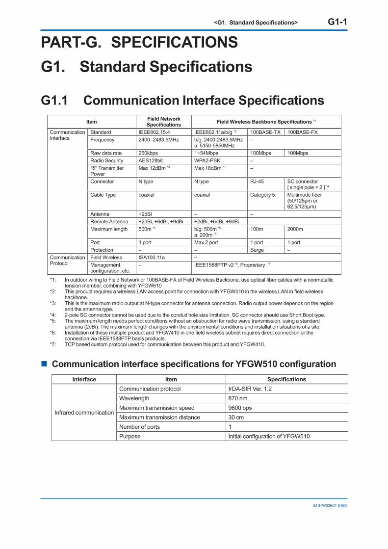
<G1. Standard Specifications> G1-1
IM 01W02E01-01EN
PART-G. SPECIFICATIONSG1. Standard Specifications
G1.1 Communication Interface SpecificationsItem Field Network
Specifications Field Wireless Backbone Specifications *1
CommunicationInterface
Standard IEEE802.15.4 IEEE802.11a/b/g *2 100BASE-TX 100BASE-FXFrequency 2400–2483.5MHz b/g: 2400-2483.5MHz
a: 5150-5850MHz–
Raw data rate 250kbps 1~54Mbps 100Mbps 100MbpsRadio Security AES128bit WPA2-PSK –RF Transmitter Power
Max 12dBm *3 Max 18dBm *3 –
Connector N type N type RJ-45 SC connector[ single pole × 2 ] *4
Cable Type coaxial coaxial Category 5 Multimode fiber(50/125μm or 62.5/125μm)
Antenna +2dBi – –Remote Antenna +2dBi, +6dBi, +9dBi +2dBi, +6dBi, +9dBi –Maximum length 500m *5 b/g: 500m *5
a: 200m *5100m 2000m
Port 1 port Max 2 port 1 port 1 portProtection – – Surge –
CommunicationProtocol
Field Wireless ISA100.11a –Management, configuration, etc.
– IEEE1588PTP v2 *6, Proprietary *7
*1: In outdoor wiring to Field Network or 100BASE-FX of Field Wireless Backbone, use optical fiber cables with a nonmetallic tension member, combining with YFGW610
*2: This product requires a wireless LAN access point for connection with YFGW410 in the wireless LAN in field wireless backbone.
*3: This is the maximum radio output at N-type connector for antenna connection. Radio output power depends on the region and the antenna type.
*4: 2-pole SC connector cannot be used due to the conduit hole size limitation. SC connector should use Short Boot type. *5: The maximum length needs perfect conditions without an obstruction for radio wave transmission, using a standard
antenna (2dBi). The maximum length changes with the environmental conditions and installation situations of a site.*6: Installation of these multiple product and YFGW410 in one field wireless subnet requires direct connection or the
connection via IEEE1588PTP basis products.*7: TCP based custom protocol used for communication between this product and YFGW410.
n Communication interface specifications for YFGW510 configurationInterface Item Specifications
Infrared communication
Communication protocol IrDA-SIR Ver. 1.2Wavelength 870 nmMaximum transmission speed 9600 bpsMaximum transmission distance 30 cmNumber of ports 1Purpose Initial configuration of YFGW510
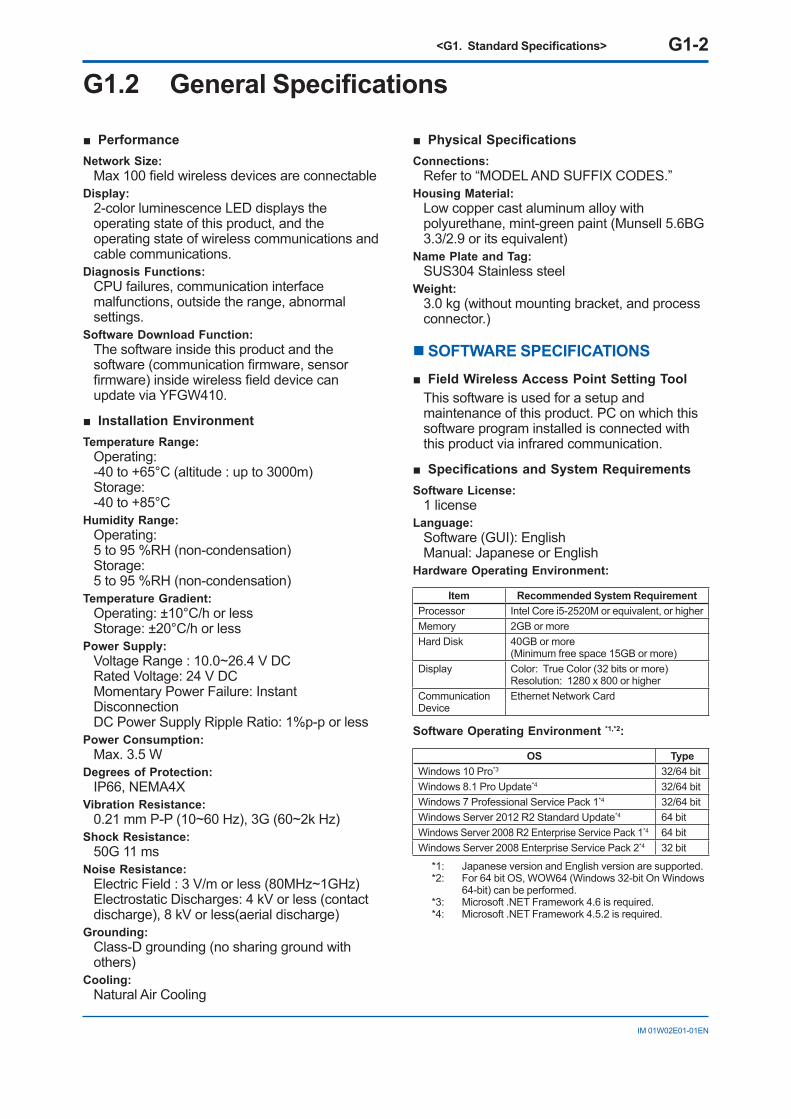
<G1. Standard Specifications> G1-2
IM 01W02E01-01EN
G1.2 General Specifications
■ PerformanceNetwork Size:
Max 100 field wireless devices are connectableDisplay:
2-color luminescence LED displays the operating state of this product, and the operating state of wireless communications and cable communications.
Diagnosis Functions: CPU failures, communication interface malfunctions, outside the range, abnormal settings.
Software Download Function: The software inside this product and the software (communication firmware, sensor firmware) inside wireless field device can update via YFGW410.
■ Installation EnvironmentTemperature Range:
Operating: -40 to +65°C (altitude : up to 3000m)Storage: -40 to +85°C
Humidity Range:Operating: 5 to 95 %RH (non-condensation)Storage: 5 to 95 %RH (non-condensation)
Temperature Gradient:Operating: ±10°C/h or lessStorage: ±20°C/h or less
Power Supply:Voltage Range : 10.0~26.4 V DCRated Voltage: 24 V DCMomentary Power Failure: Instant DisconnectionDC Power Supply Ripple Ratio: 1%p-p or less
Power Consumption:Max. 3.5 W
Degrees of Protection:IP66, NEMA4X
Vibration Resistance: 0.21 mm P-P (10~60 Hz), 3G (60~2k Hz)
Shock Resistance: 50G 11 ms
Noise Resistance: Electric Field : 3 V/m or less (80MHz~1GHz) Electrostatic Discharges: 4 kV or less (contact discharge), 8 kV or less(aerial discharge)
Grounding:Class-D grounding (no sharing ground with others)
Cooling:Natural Air Cooling
■ Physical SpecificationsConnections:
Refer to “MODEL AND SUFFIX CODES.”Housing Material:
Low copper cast aluminum alloy with polyurethane, mint-green paint (Munsell 5.6BG 3.3/2.9 or its equivalent)
Name Plate and Tag:SUS304 Stainless steel
Weight:3.0 kg (without mounting bracket, and process connector.)
n SOFTWARE SPECIFICATIONS■ Field Wireless Access Point Setting Tool
This software is used for a setup and maintenance of this product. PC on which this software program installed is connected with this product via infrared communication.
■ Specifications and System RequirementsSoftware License:
1 licenseLanguage:
Software (GUI): EnglishManual: Japanese or English
Hardware Operating Environment:
Item Recommended System RequirementProcessor Intel Core i5-2520M or equivalent, or higherMemory 2GB or moreHard Disk 40GB or more
(Minimum free space 15GB or more) Display Color: True Color (32 bits or more)
Resolution: 1280 x 800 or higherCommunication Device
Ethernet Network Card
Software Operating Environment *1,*2:
OS TypeWindows 10 Pro*3 32/64 bitWindows 8.1 Pro Update*4 32/64 bitWindows 7 Professional Service Pack 1*4 32/64 bitWindows Server 2012 R2 Standard Update*4 64 bitWindows Server 2008 R2 Enterprise Service Pack 1*4 64 bitWindows Server 2008 Enterprise Service Pack 2*4 32 bit
*1: Japanese version and English version are supported.*2: For 64 bit OS, WOW64 (Windows 32-bit On Windows
64-bit) can be performed.*3: Microsoft .NET Framework 4.6 is required.*4: Microsoft .NET Framework 4.5.2 is required.
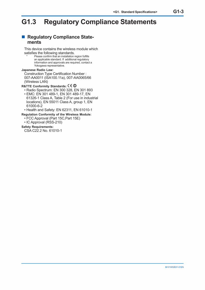
<G1. Standard Specifications> G1-3
IM 01W02E01-01EN
G1.3 Regulatory Compliance Statements
n Regulatory Compliance State-ments
This device contains the wireless module which satisfies the following standards.
* Please confirm that an installation region fulfills an applicable standard. If additional regulatory information and approvals are required, contact a Yokogawa representative.
Japanese Radio Law:Construction Type Certification Number : 007-AA0011 (ISA100.11a), 007-AA0065/66 (Wireless LAN)
R&TTE Conformity Standards: • Radio Spectrum: EN 300 328, EN 301 893• EMC: EN 301 489-1, EN 301 489-17, EN
61326-1 Class A, Table 2 (For use in industrial locations), EN 55011 Class A, group 1, EN 61000-6-2
• Health and Safety: EN 62311, EN 61010-1Regulation Conformity of the Wireless Module:
• FCC Approval (Part 15C,Part 15E) • IC Approval (RSS-210)
Safety Requirements:CSA C22.2 No. 61010-1
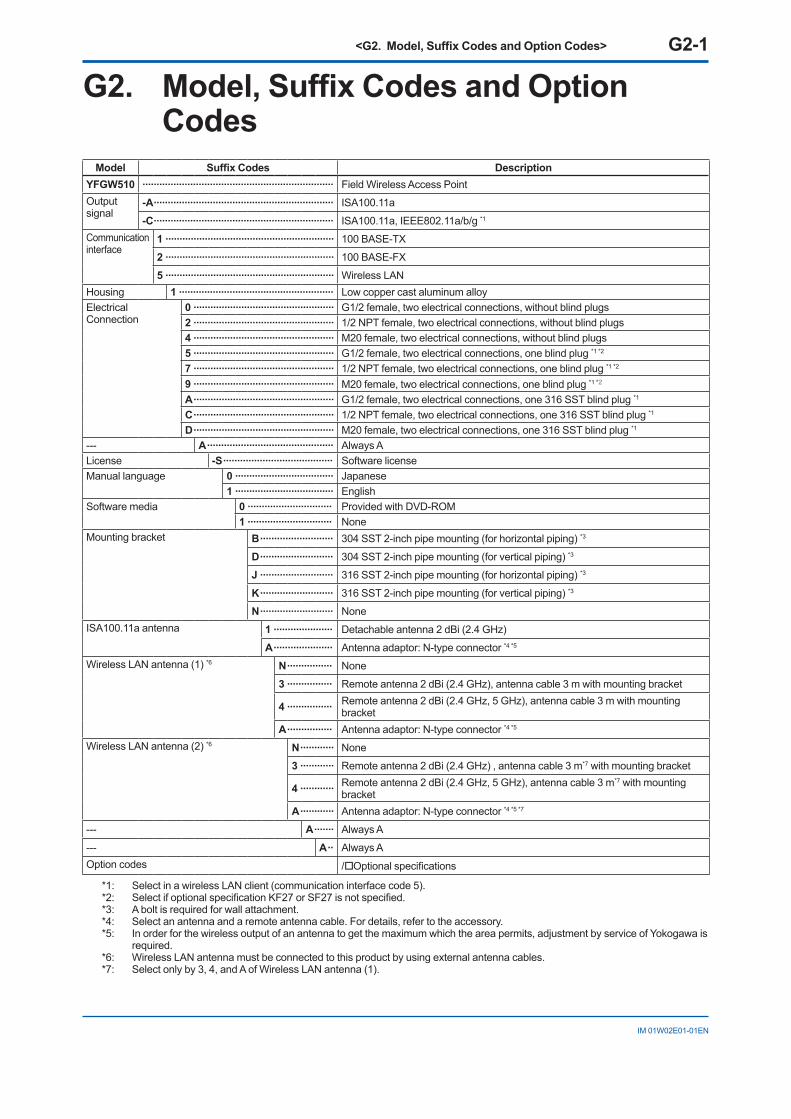
<G2. Model, Suffix Codes and Option Codes> G2-1
IM 01W02E01-01EN
G2. Model, Suffix Codes and Option Codes
Model Suffix Codes DescriptionYFGW510 �������������������������������������������������������������������� Field Wireless Access PointOutput signal
-A ���������������������������������������������������������������� ISA100.11a
-C ���������������������������������������������������������������� ISA100.11a, IEEE802.11a/b/g *1
Communication interface
1 ������������������������������������������������������������ 100 BASE-TX
2 ������������������������������������������������������������ 100 BASE-FX
5 ������������������������������������������������������������ Wireless LANHousing 1 ������������������������������������������������������� Low copper cast aluminum alloyElectrical Connection
0 �������������������������������������������������� G1/2 female, two electrical connections, without blind plugs2 �������������������������������������������������� 1/2 NPT female, two electrical connections, without blind plugs4 �������������������������������������������������� M20 female, two electrical connections, without blind plugs5 �������������������������������������������������� G1/2 female, two electrical connections, one blind plug *1 *2
7 �������������������������������������������������� 1/2 NPT female, two electrical connections, one blind plug *1 *2
9 �������������������������������������������������� M20 female, two electrical connections, one blind plug *1 *2
A �������������������������������������������������� G1/2 female, two electrical connections, one 316 SST blind plug *1
C �������������������������������������������������� 1/2 NPT female, two electrical connections, one 316 SST blind plug *1
D �������������������������������������������������� M20 female, two electrical connections, one 316 SST blind plug *1
--- A ��������������������������������������������� Always ALicense -S ��������������������������������������� Software licenseManual language 0 ����������������������������������� Japanese
1 ����������������������������������� EnglishSoftware media 0 ������������������������������ Provided with DVD-ROM
1 ������������������������������ NoneMounting bracket B �������������������������� 304 SST 2-inch pipe mounting (for horizontal piping) *3
D �������������������������� 304 SST 2-inch pipe mounting (for vertical piping) *3
J �������������������������� 316 SST 2-inch pipe mounting (for horizontal piping) *3
K �������������������������� 316 SST 2-inch pipe mounting (for vertical piping) *3
N �������������������������� NoneISA100.11a antenna 1 ��������������������� Detachable antenna 2 dBi (2.4 GHz)
A ��������������������� Antenna adaptor: N-type connector *4 *5
Wireless LAN antenna (1) *6 N ���������������� None
3 ���������������� Remote antenna 2 dBi (2.4 GHz), antenna cable 3 m with mounting bracket
4 ���������������� Remote antenna 2 dBi (2.4 GHz, 5 GHz), antenna cable 3 m with mounting bracket
A ���������������� Antenna adaptor: N-type connector *4 *5
Wireless LAN antenna (2) *6 N ������������ None
3 ������������ Remote antenna 2 dBi (2.4 GHz) , antenna cable 3 m*7 with mounting bracket
4 ������������ Remote antenna 2 dBi (2.4 GHz, 5 GHz), antenna cable 3 m*7 with mounting bracket
A ������������ Antenna adaptor: N-type connector *4 *5 *7
--- A ������� Always A
--- A �� Always AOption codes /Optional specifications
*1: Select in a wireless LAN client (communication interface code 5).*2: Select if optional specification KF27 or SF27 is not specified.*3: A bolt is required for wall attachment.*4: Select an antenna and a remote antenna cable. For details, refer to the accessory.*5: In order for the wireless output of an antenna to get the maximum which the area permits, adjustment by service of Yokogawa is
required.*6: Wireless LAN antenna must be connected to this product by using external antenna cables.*7: Select only by 3, 4, and A of Wireless LAN antenna (1).
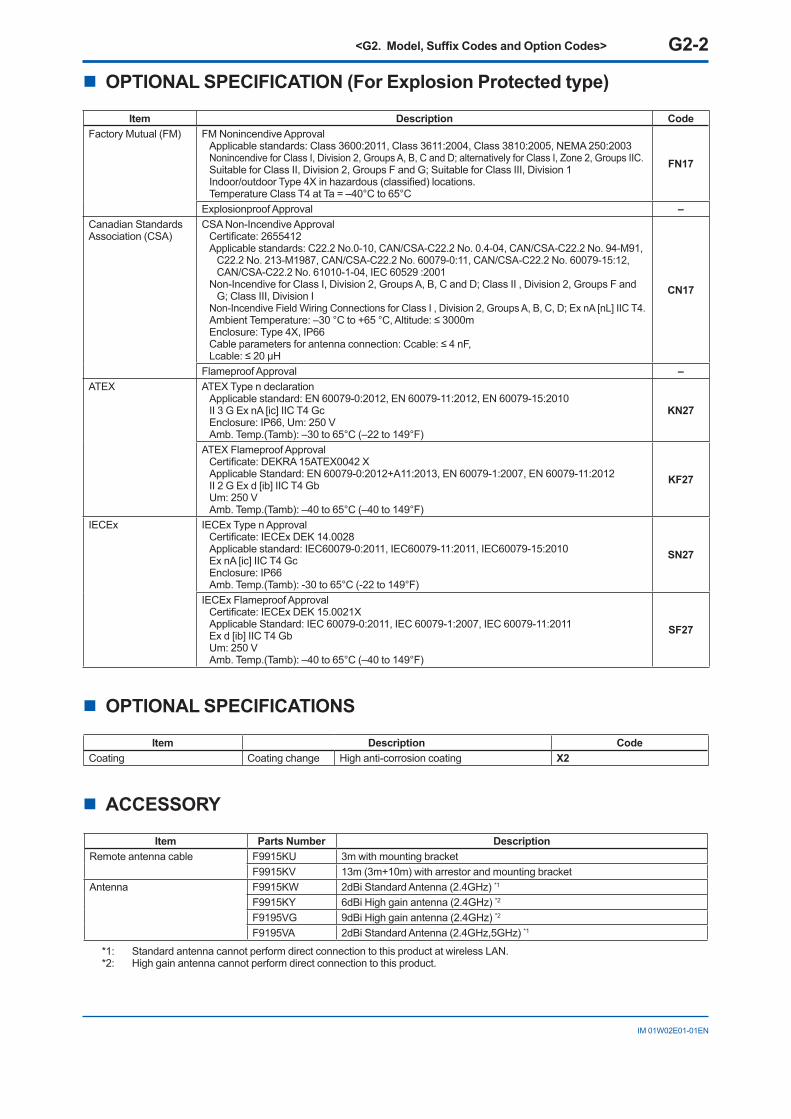
<G2. Model, Suffix Codes and Option Codes> G2-2
IM 01W02E01-01EN
n OPTIONAL SPECIFICATION (For Explosion Protected type)
Item Description CodeFactory Mutual (FM) FM Nonincendive Approval
Applicable standards: Class 3600:2011, Class 3611:2004, Class 3810:2005, NEMA 250:2003 Nonincendive for Class I, Division 2, Groups A, B, C and D; alternatively for Class I, Zone 2, Groups IIC.Suitable for Class II, Division 2, Groups F and G; Suitable for Class III, Division 1 Indoor/outdoor Type 4X in hazardous (classified) locations. Temperature Class T4 at Ta = –40°C to 65°C
FN17
Explosionproof Approval –Canadian Standards Association (CSA)
CSA Non-Incendive Approval Certificate: 2655412 Applicable standards: C22.2 No.0-10, CAN/CSA-C22.2 No. 0.4-04, CAN/CSA-C22.2 No. 94-M91,
C22.2 No. 213-M1987, CAN/CSA-C22.2 No. 60079-0:11, CAN/CSA-C22.2 No. 60079-15:12, CAN/CSA-C22.2 No. 61010-1-04, IEC 60529 :2001
Non-Incendive for Class I, Division 2, Groups A, B, C and D; Class II , Division 2, Groups F and G; Class III, Division I
Non-Incendive Field Wiring Connections for Class I , Division 2, Groups A, B, C, D; Ex nA [nL] IIC T4. Ambient Temperature: –30 °C to +65 °C, Altitude: ≤ 3000m Enclosure: Type 4X, IP66 Cable parameters for antenna connection: Ccable: ≤ 4 nF, Lcable: ≤ 20 μH
CN17
Flameproof Approval –ATEX ATEX Type n declaration
Applicable standard: EN 60079-0:2012, EN 60079-11:2012, EN 60079-15:2010 II 3 G Ex nA [ic] IIC T4 Gc Enclosure: IP66, Um: 250 V Amb. Temp.(Tamb): –30 to 65°C (–22 to 149°F)
KN27
ATEX Flameproof Approval Certificate: DEKRA 15ATEX0042 X Applicable Standard: EN 60079-0:2012+A11:2013, EN 60079-1:2007, EN 60079-11:2012 II 2 G Ex d [ib] IIC T4 Gb Um: 250 V Amb. Temp.(Tamb): –40 to 65°C (–40 to 149°F)
KF27
IECEx IECEx Type n Approval Certificate: IECEx DEK 14.0028 Applicable standard: IEC60079-0:2011, IEC60079-11:2011, IEC60079-15:2010 Ex nA [ic] IIC T4 Gc Enclosure: IP66 Amb. Temp.(Tamb): -30 to 65°C (-22 to 149°F)
SN27
IECEx Flameproof Approval Certificate: IECEx DEK 15.0021X Applicable Standard: IEC 60079-0:2011, IEC 60079-1:2007, IEC 60079-11:2011 Ex d [ib] IIC T4 Gb Um: 250 V Amb. Temp.(Tamb): –40 to 65°C (–40 to 149°F)
SF27
n OPTIONAL SPECIFICATIONS
Item Description CodeCoating Coating change High anti-corrosion coating X2
n ACCESSORY
Item Parts Number DescriptionRemote antenna cable F9915KU 3m with mounting bracket
F9915KV 13m (3m+10m) with arrestor and mounting bracketAntenna F9915KW 2dBi Standard Antenna (2.4GHz) *1
F9915KY 6dBi High gain antenna (2.4GHz) *2
F9195VG 9dBi High gain antenna (2.4GHz) *2
F9195VA 2dBi Standard Antenna (2.4GHz,5GHz) *1
*1: Standard antenna cannot perform direct connection to this product at wireless LAN.*2: High gain antenna cannot perform direct connection to this product.
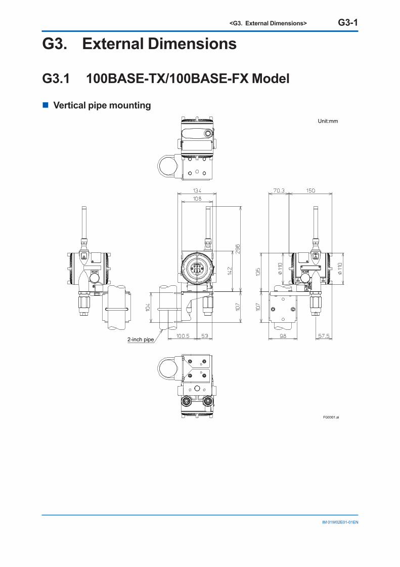
<G3. External Dimensions> G3-1
IM 01W02E01-01EN
G3. External Dimensions
G3.1 100BASE-TX/100BASE-FX Model
n Vertical pipe mounting
FG0301.ai
2-inch pipe
Unit:mm
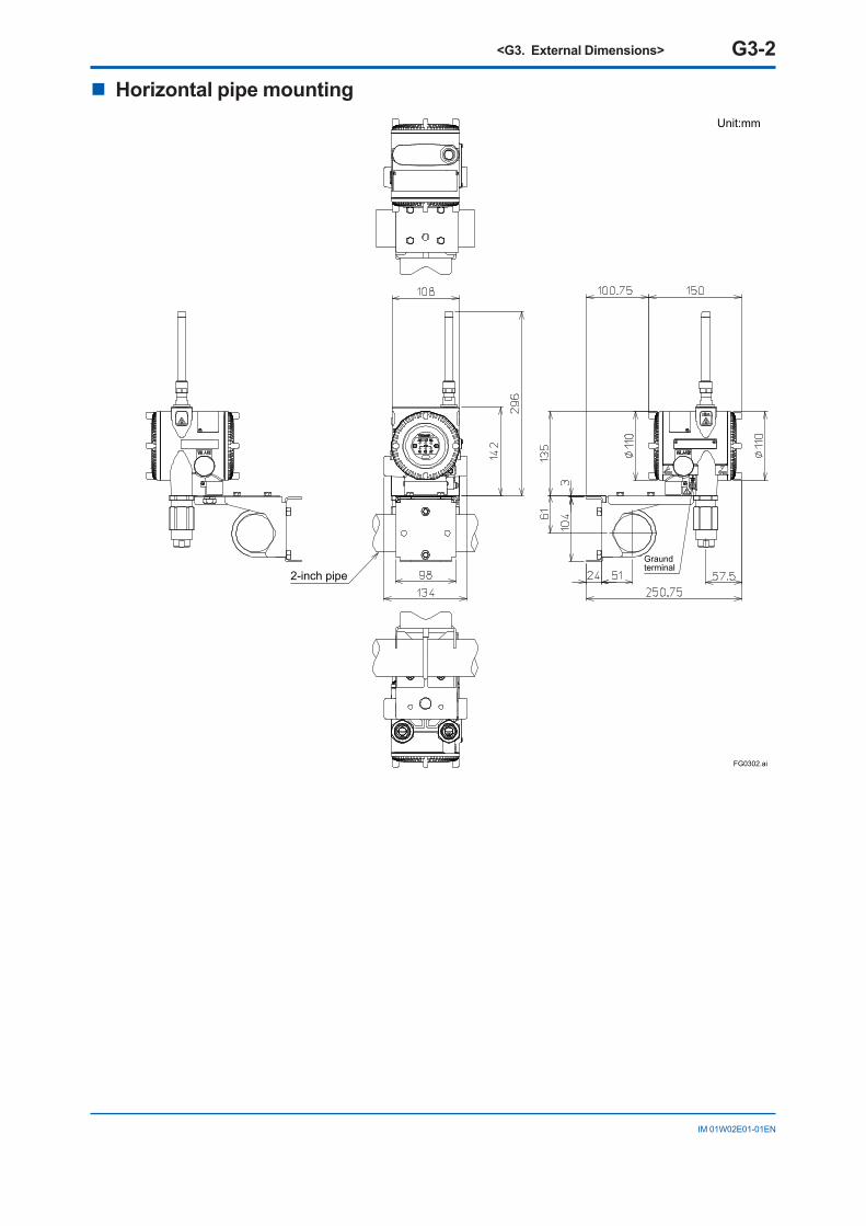
<G3. External Dimensions> G3-2
IM 01W02E01-01EN
n Horizontal pipe mounting
FG0302.ai
2-inch pipeGraund terminal
Unit:mm
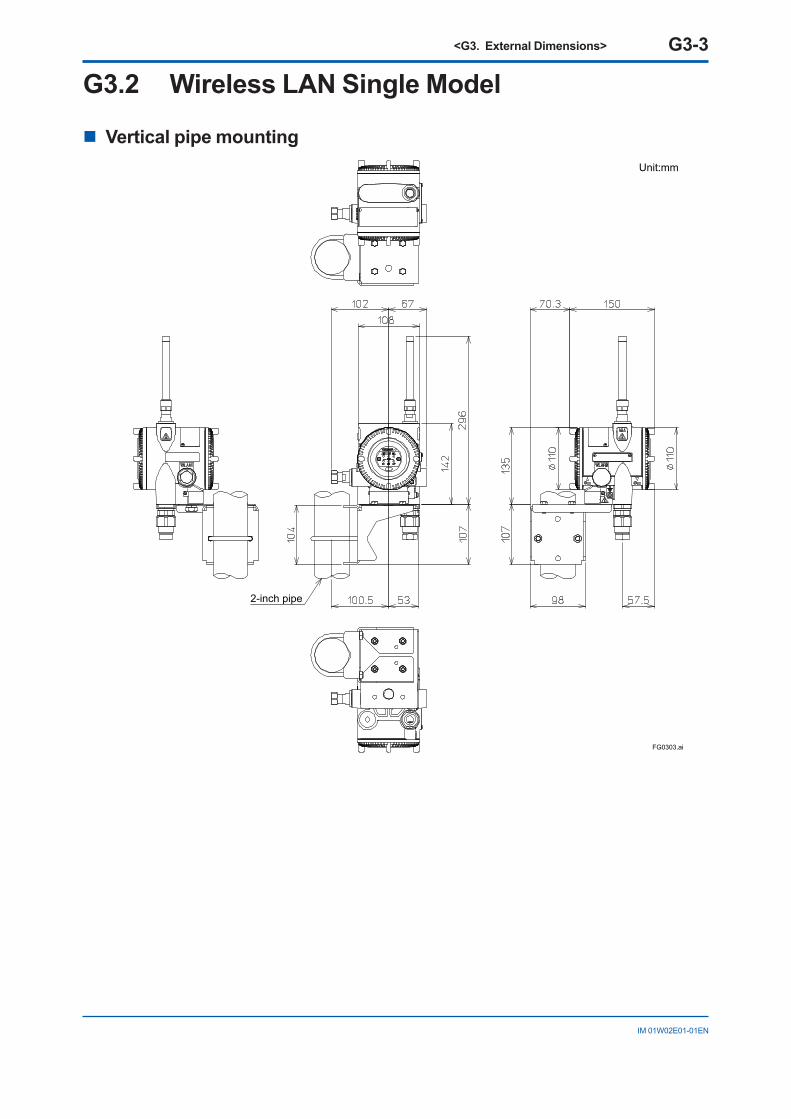
<G3. External Dimensions> G3-3
IM 01W02E01-01EN
G3.2 Wireless LAN Single Model
n Vertical pipe mounting
FG0303.ai
2-inch pipe
Unit:mm
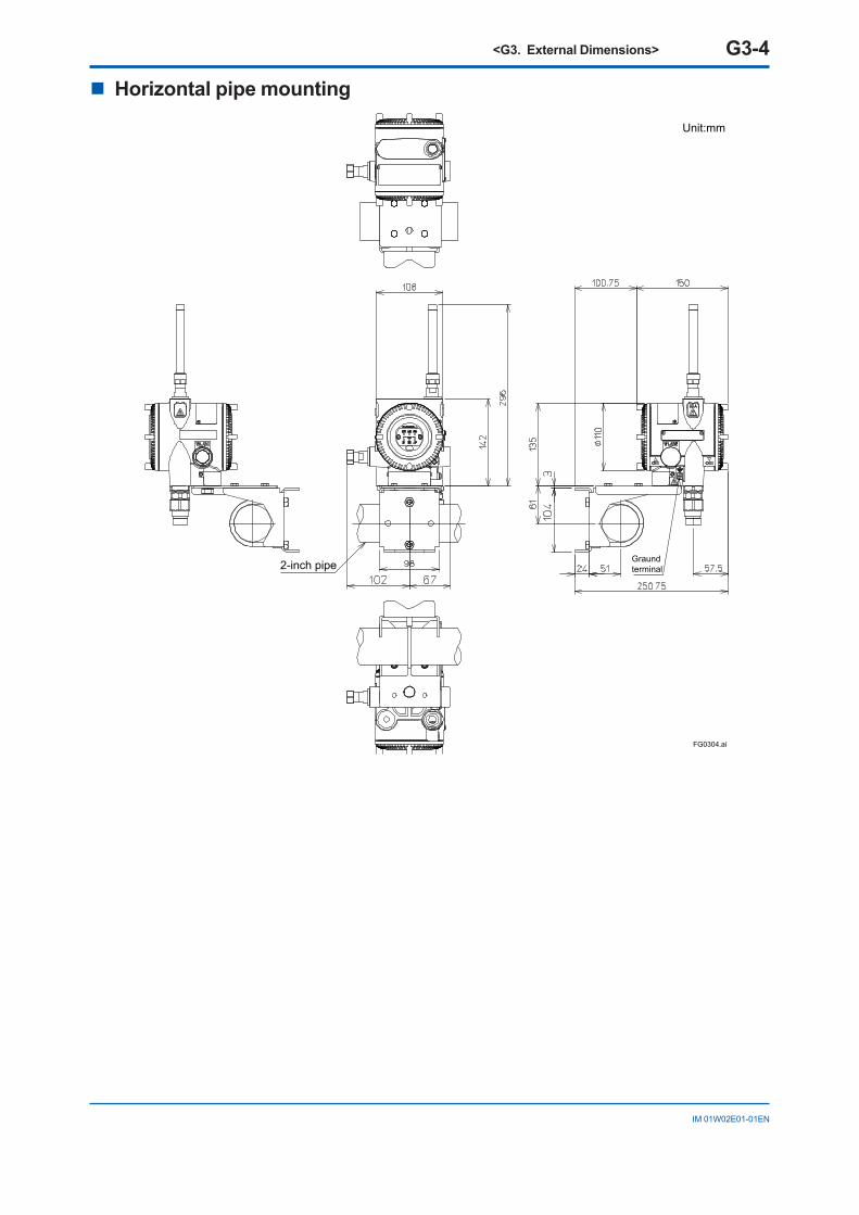
<G3. External Dimensions> G3-4
IM 01W02E01-01EN
n Horizontal pipe mounting
FG0304.ai
2-inch pipe Graund terminal
Unit:mm
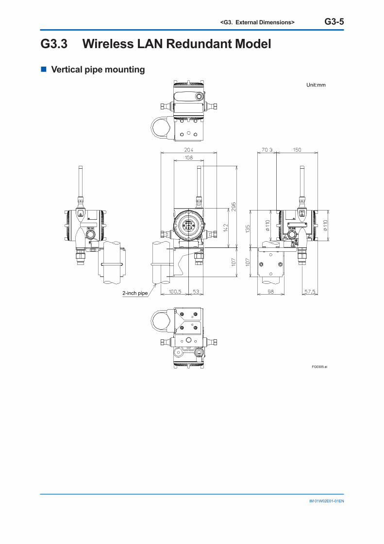
<G3. External Dimensions> G3-5
IM 01W02E01-01EN
G3.3 Wireless LAN Redundant Model
n Vertical pipe mounting
FG0305.ai
2-inch pipe
Unit:mm
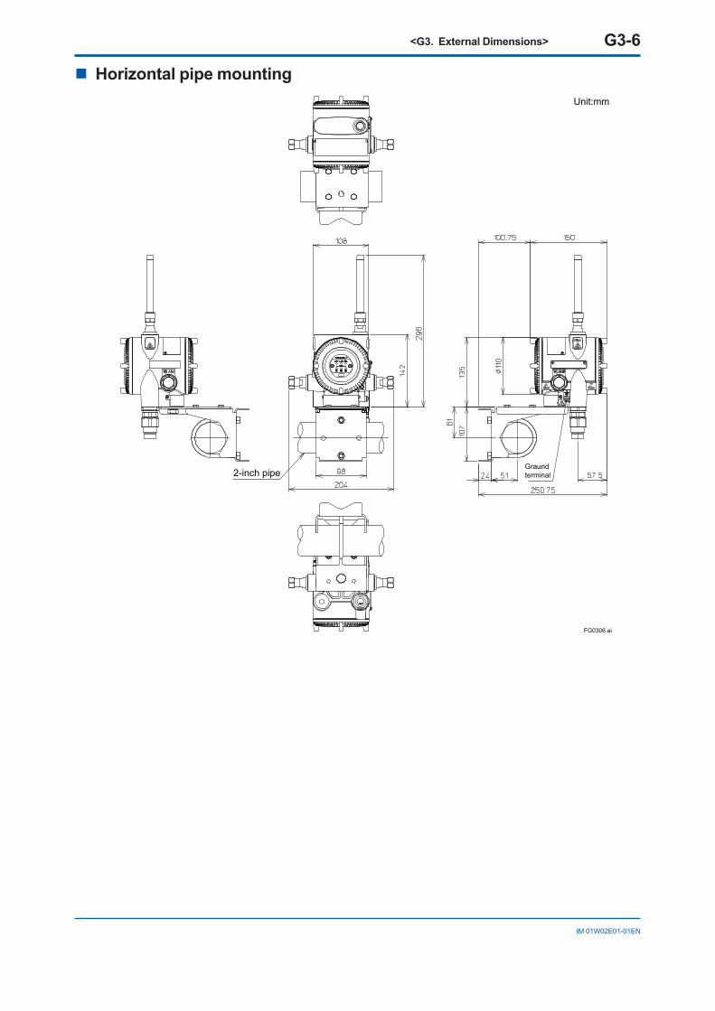
<G3. External Dimensions> G3-6
IM 01W02E01-01EN
n Horizontal pipe mounting
FG0306.ai
2-inch pipeGraund terminal
Unit:mm