Embed Size (px)
Citation preview
USER'S MANUAL
TIG200AC/DCP
- 1 -
Contents
1、Safety warning..................................................................................................................... 2
2、Description of the machine................................................................................................. 3
3、Table of technical parameters ............................................................................................ 4
4、Explanation of panel ........................................................................................................... 5
5、Instructions on installation................................................................................................. 6
6、Instructions on operation ................................................................................................... 8
7、Routine maintenance ........................................................................................................ 10
8、Precautions before the overhaul ...................................................................................... 10
9、Precautions and preventive measures ............................................................................. 11
10、Troubles may be encountered in welding...................................................................... 12
11、Troubleshooting ............................................................................................................... 13
- 2 -
Safety Warning!
In arc welding and cutting process protective measures should be taken as injuries may be done to you and others. For details refer to the safety protection guide to operators that meets the manufacturers’ requirements for accident prevention.
Electric shock---may lead to death!! ·Grounding devices should be installed according to the applicable standards. ·Touch with live parts or welding electrodes by an operator with exposed skin, in wet gloves
or clothes is prohibited. ·Make sure insulation exists between you and the ground and the work piece. ·Make sure that your operating position is in a safe state. Smoke---may be harmful to health! ·The head should be kept away from smoke. ·In arc welding a ventilator or air exhauster should be used to avoid inhalation of welding
gas. Arc light radiation----may harm your eyes and burn your skin! ·Wear exposure suit ,a suitable welding helmet and filter lens to protect your eyes and body. ·Appropriate welding helmets or curtains should be used to protect spectators from injury.
Fire
·Welding spark may lead to fire. Please make sure no combustibles exist near the welding position.
Noise----too much noise will do harm to your ears! ·Protect your ear by wearing ear cover or other hearing protections. ·Spectators should be warned that noise will do potential harm to their sense of hearing. Fault----when in trouble, seek help from professionals! ·If you meet with any difficulty in installation and operation, inspect one by one according to
relevant content of this manual. ·If you are still unable to understand the content after reading the guide or find no solution
according to the guide, you should immediately contact your supplier
Warning! Leakage protection switch should be installed additionally to this equipment!!!
- 3 -
Description of this welder
The welder adopts rectifier designed with advanced inverter technology. The advent of inverter arc welding machine derives from inverter power theory and devices.
The inverter arc welding power uses high-power device MOSFET field-effect transistor to turn the working frequency of 50/60Hz to high frequency (such as 100KHz or higher). Then voltage is reduced and current is regulated. A powerful DC power source can be produced by using the pulse width modulation (PWM)technology. The weight and volume of the main transformer of the welder are reduced remarkably, and the efficiency is increased by 30%. The advent of inverter welding machine is regard as a revolution of the welding machine industry.
This product is a dual-purpose machine composed of DC pulse argon arc welder and AC argon arc welder, whose most important feature is a machine with multiple purposes, you can achieve the welding for a various metal by a various ways without having to change machines. DC pulse argon arc welding can achieve high-quality welding for the plate, various metals, different thickness and double-sided forming process. AC argon arc welding adopts double-time inverter techniques and a pure square wave output, making a feature of a good arc stiffness, heat concentration, strong reverse cleaning capability, wide cleaning range and so on, to ensure the welder good welding characteristics, suitable for welding aluminum and aluminum alloy products.
We welcome friends from all walks of life to use the products and present valuable suggestions to us. We’ll devote ourselves to providing customers with perfect products and services.
Warning!
This equipment is mainly used in the industrial sector. In an indoor environment it
may produce radio jamming and operators should adopt adequate preventive measures.
- 4 -
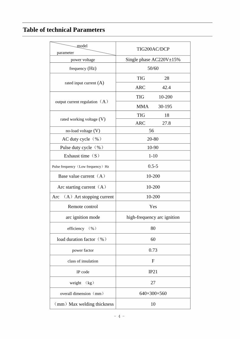
Table of technical Parameters
model parameter
TIG200AC/DCP
power voltage Single phase AC220V±15%
frequency (Hz) 50/60
TIG 28 rated input current (A)
ARC 42.4
TIG 10-200 output current regulation(A)
MMA 30-195
TIG 18 rated working voltage (V)
ARC 27.8 no-load voltage (V) 56
AC duty cycle(%) 20-80
Pulse duty cycle(%) 10-90
Exhaust time(S) 1-10
Pulse frequency(Low frequency)Hz 0.5-5
Base value current(A) 10-200
Arc starting current(A) 10-200
Arc (A)Art stopping current 10-200
Remote control Yes
arc ignition mode high-frequency arc ignition
efficiency (%) 80
load duration factor(%) 60
power factor 0.73
class of insulation F
IP code IP21
weight (kg) 27
overall dimension(mm) 640×300×560
(mm)Max welding thickness 10
- 5 -
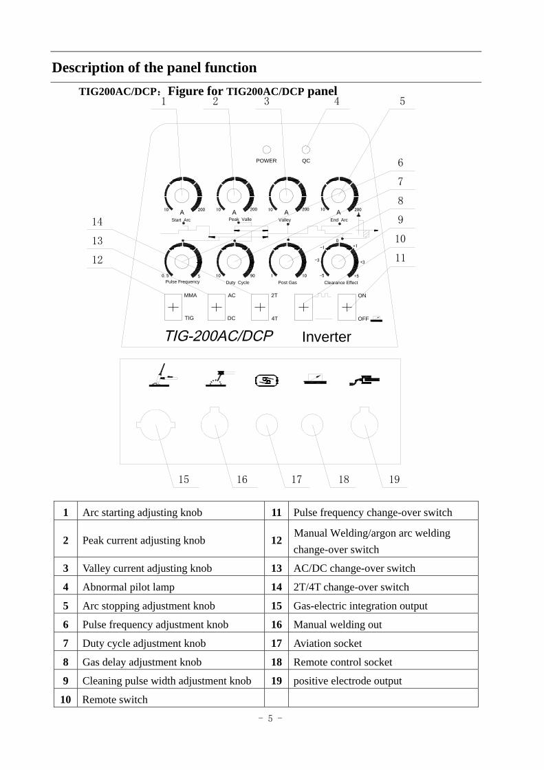
Description of the panel function
TIG200AC/DCP:Figure for TIG200AC/DCP panel
1 Arc starting adjusting knob 11 Pulse frequency change-over switch
2 Peak current adjusting knob 12change-over switch
3 Valley current adjusting knob 13 AC/DC change-over switch
4 Abnormal pilot lamp 14 2T/4T change-over switch
5 Arc stopping adjustment knob 15 Gas-electric integration output
6 Pulse frequency adjustment knob 16 Manual welding out
7 Duty cycle adjustment knob 17 Aviation socket
8 Gas delay adjustment knob 18 Remote control socket
9 Cleaning pulse width adjustment knob 19 positive electrode output
10 Remote switch
POWER QC
10
Inverter
10 200 20010 20010 20010
1901050.5
A
Pulse Frequency Post Gas Clearance Effect+5
+3
+10
-1
-3
-5
End ArcAAA
ValleyPeak ValleStart Arc
Duty Cycle
OFF
ON
4T
2TAC
DCTIG
MMA
15 16 17 18 19
12
13
14
6
7
8
11
10
9
4 51 2 3
Manual Welding/argon arc welding
- 6 -
Instructions on installation The welder is fitted with power voltage compensation device. When power voltage changes
within a range of 15% of rated voltage, it can go on with the operation.
If a longer cable wire is used, , we suggest using cable with greater cross section in order to reduce line loss voltage; if a connecting cable is too long, it may exert a great effect upon the arc starting of the welder and other performance of the system, such as weakened high-frequency arc starting or failure of the system to work regularly. So we suggest that you use recommended configuration length.
1、Make sure that the vent of the welder is not covered or plugged to avoid failure of the cooling system. 2、Protective gas source should be connected well. Gas supply passage should include gas
cylinder, argon decompression flow-meter and gas pipe. The connecting portion of the gas pipe should be tied up with a hose clamp or other objects to prevent leakage and air intake.
3、The shell should be grounded reliably with a conducting wire with a sectional area not less than 6mm2.
4、The quick plug of the loop cable is inserted into the quick socket of welder surface plate with the polarity of “+” and tightened clockwise. The ground wire pliers at the other end hold up the work piece.
5、Mount water sniper correctly as shown in the figure. Connect the copper nut from the other end of the welder with the gas electric integration from the front panel, and tightened clockwise firmly.
6、When the pedal switch is used to control, Connect the 2-core aviation plug and 3-core aviation plug of the pedal switch with the 2-core aviation socket and 3-core aviation socket.
7、Based on the input voltage class of the welder, the power line should be connected to the distribution box of corresponding voltage class and non-corresponding connection should never occur . Make sure that error in power voltage is within a permissible range.
After completion of the above job, installation of the welder comes to an end and welding can begin.
- 7 -
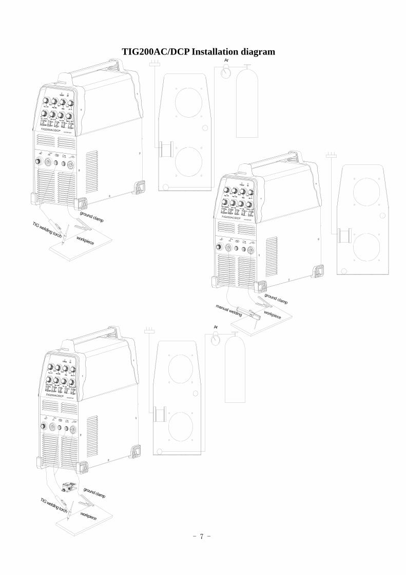
TIG200AC/DCP Installation diagram
TIG200AC/DCPINVERTER
Ar
workpiece
TIG welding torch
ground clampTIG200AC/DCP INVERTER
workpiece
manual welding
ground clamp
INVERTER
TIG200AC/DCP
Ar
TIG welding torch workpiece
ground clamp
- 8 -
Operation Instructions
(1)Instructions on DC argon arc welding 1、Open the power switch on the front panel, the digital current meter displays regularly and the blower
fan in the machine begins to work.
2、 Open the valve of argon cylinder to regulate the flow meter to the required value. 3、 If AC/DC conversion switch is turned to DC mode, DC argon arc welding will take place for
such metals as stainless steel, iron and copper.
4、When Local/Remote conversion switch is turned to OFF mode, the current will be regulated by the panel button; when the conversion switch is turned to ON mode, the welding current will be regulated by the pedal switch.
5、 Pulse Selection Switch is to be selected as required. When put to the lower gear, no pulse will occur whereas upper gear will result in low-frequency pulse (at a frequency of 0.5-5Hz) and at the same time the frequency button should be regulated to the appropriate pulse frequency.
6、 Pulse duty factor should be regulated to an appropriate position in line with the requirement for the work piece to be welded (the duty factor should be 1 when no pulse is available).
7、 The value of arc starting current and crater current should be regulated in line with the requirement for the work piece to be welded.
8、 The corresponding peak current and valley current should be set in line with the thickness of the work piece to be welded(if the pulse switch is put to the lower gear, no basic current will occur).
9、 Press down the control button on the welding torch and then the solenoid valve in the machine will be actuated and a high-frequency arc ignition discharge sound will be heard with argon gas flowing out of the welding torch.
10、The tungsten electrode of the welding torch is 2-4 mm from the work piece. If the button is pressed down for arc ignition, the high-frequency discharge sound in the machine will disappear. Then you can start work.
11、At the end of welding, to protect the welding bead better, the rear gas delivery button should be adjusted to an appropriate position.
12、In argon arc welding, for long welding and spot welding, 2T/4T switch may be selected. At 2T the arc starting current and crater current won’t serve the purpose and only the welding current works.
13、At 4T when the switch on the welding torch is pressed down, arc starting current occurs while releasing the switch, welding current occurs. If the switch is pressed down once more, crater current will occur while releasing the switch, the torch will stop working.
- 9 -
(2)Instructions on AC argon arc welding 1、If AC/DC conversion switch is put to AC gear as instructed above in steps 1-4, AC argon arc
welding will start for aluminum materials. 2、The pulse width button can be adjusted in line with the oxidation of the work piece surface to be
welded: in AC argon arc welding the current is converted alternately in one forward direction and one backward direction. When the current flows from the tungsten needle to the work piece, it is the time for reverse current and the oxidized layer on the surface of work piece can be cleaned up for better welding effect, but the tungsten needle will be burned down due to heat generation. This button is provided for regulating the ratio between the forward and backward current time.
3、 Operate as instructed in Steps 10-12 above. Note:
(1) A smaller pulse duty factor should be used for greater current; for example, a pulse duty factor of less than 30% should be selected for over 200A. A greater pulse duty factor should be used for smaller current; for example, a pulse duty factor of more than 50% should be selected for less than 100A.
(2) As in AC argon arc welding no arc will be ignited at a minimum current, the current has to be preset to 20A.
Warning: Inserting or pulling out any cable wire or plug being used in welding is strictly
prohibited as this operation will endanger people and result in destruction of equipment.
- 10 -
Routine maintenance
Warning: All the maintenance and repair jobs must be carried out when the power is cut-off
completely. Make sure the power plug is disconnected before opening the shell.
1 Dust should be removed with dry and clean compressed air regularly. If the welder is used in a heavily polluted environment with dense smoke and polluted air, dust must be removed from the welder each month.
2 The pressure of compressed air should be reasonable so that damage is not done to small elements in the welder.
3 Regularly check the connection of electric circuit in the welder and make sure circuit be connected properly and joint is secured (especially inserted joint or element). If the cases of rusting or loosening are found, the rust layer or oxidized film should be removed with abrasive paper and then the joint should be connected again and tightened firmly.
4 Entry of water or steam into the interior of the welder should be avoided. If this condition occurs, the welder should undergo drying treatment. Then the welder is measured for insulation by a megohm-meter (including the area between connecting points and the areas between the connecting points and shell). Welding can go on only when evidence shows no abnormality.
5 If the welder is not to be used for a long time, it should be replaced in the original package and kept in a dry environment.
Precautions before repairs
Warning
A haphazard experiment and imprudent repair may lead to expansion of fault area, making formal repair more difficult. The exposed part of the welder in energization carries high voltage
that may lead to hazards and any direct or indirect touch with it will result in electric shock accident. In serious
case death may occur
If in the warranty period the user carries out an erroneous examination and repair of any fault in the welding and cutting power without permission, the free maintenance warranty offered by the supplier will be invalidated.
- 11 -
Precautions or preventive measures
1、Environment 1)Welding operation should be carried out in a relatively dry environment with air humidity
usually less than 90%.
2)Ambient temperature should be kept between -10 C ~40 C.
3)Welding in the sun or rain should be avoided and water or rainwater should never be seeped into the welder interior.
4)Welding in the dusty area or under a corrosive gas environment should be avoided. 5)Gas protection welding operation in an environment with strong air flow should be avoided. 2、Essentials for safety
In this welder over-voltage, over-current and overheat protection circuits have been installed beforehand. When the grid voltage, output current and machine temperature surpass the set standards, the machine will stop automatically. But excessive use (for example, when the voltage is too high) can still lead to the breakdown of the welder. So you have to pay attention to the following items:
1)Good ventilation! This machine is a small type welder. In operation a high working current flows in and natural ventilation is unable to meet the welder’s requirement for cooling. So a fan is fitted to effectively cool the welder to keep it work smoothly. Operators should make sure that the vent is not covered or plugged, the distance of the welder from its surrounding objects is not less than 0.3 m and good ventilation is kept all the time. All these are very important for better operation of the welder and longer service life of the welder.
2)No overload! Operators should bear in mind that maximum permissible load current (relative to the selected load duration factor) be observed at any time and welding current should never surpass the maximum permissible load current. Over-current will shorten the service life of the welder remarkably and even burn it down.
3)No over-voltage! Power voltage is shown in the main performance parameter table. In general, the voltage auto-compensation circuit in the welder will ensure the welding current remain within the permissible range. If power voltage surpasses the permissible value, the welder will be broken down. Operators should fully know this and adopt corresponding preventive measures.
4)Behind each welder there is a grounding screw with the grounding mark. Before operation the
o o
- 12 -
shell of the welder should be grounded reliably by a cable wire with a sectional area bigger than 6mm2 so as to release static electricity or prevent any accident due to leakage.
5)If the welding machine exceeds the standard load duration factor in operation, it may probably go into a protective state suddenly and stop work, which indicates it has exceeded the standard load duration factor. Excessive heating triggers the temperature control switch and makes the welding machine stop operation. Under such circumstances you needn’t turn off the power so that the cooling fan may work continuously for cooling. When the temperature drops to the standard range, welding may be restarted.
Troubles may be encountered in welding Phenomena enumerated here may have something to do with the parts, gas, environmental factors and power supply you use and efforts should be made in improving the environment to avoid occurrence of such cases.
A、 Black welding spot ——This shows the welding spot is oxidized without being protected effectively and you can make the following inspection : 1. Make sure that the valve of argon cylinder has been opened with sufficient pressure. As a rule,
if the pressure within the cylinder is lower than 0.5MPa, then it is necessary to refill the cylinder.
2. Check if the argon flow-meter is turned on with sufficient flow. You can select different flow rates in light of varying welding current, but too small flow may lead to inadequate gas stiffness and thus failure to cover all the welded spots. We suggest argon flow should never be lower than 3l/min no matter how weak the current will be.
3. The easiest way to check gas delivery is to touch the nozzle of welding torch to see whether the gas passage of the welding torch is blocked.
4. Poor sealing of gas passage or lower gas purity will also give rise to welding quality trouble. 5. Strong air flow in the environment may also lead to deterioration of welding quality. B、Difficulty in arc starting with easy arc breaking: 1. Make sure that the tungsten electrode in use is of good quality as discharge ability of inferior
tungsten electrode may fail the requirement; 2. Tungsten electrode without sharpening treatment is also unable to start arc and leads to
unstable arc. C、Output current can’t reach the rated value:
Deviation of power voltage from the rated value will lead to unconformity of output current value with the set value. When power voltage is lower than the rated value, maximum output current of the welder may also be lower than the rated value.
- 13 -
D、Unstable current in the operation of the welder: This may be attributed to the following factors: 1. Change in grid voltage; 2. Interference from the power grid or other power equipments. E、:Severely burn of the tungsten needle The duty cycle is adjusted too large, causing emission from the workpiece to the tungsten electron for too long, resulting in severe heat of the tungsten needles. F、The oxide film can’t be torn when welding aluminum: 1. the welding gear is selected wrong. 2. The duty cycle is adjusted too small; 3. The secondary inverter has field pipe damage. G、The abnormal pilot lamp is on:
1、The light is on when the welder work abnormally, please turn off the power switch and then reboot the machine, it can continue to use if it return to normal,
2、If the light is on repeatedly, please refer to the professional or the manufacturer for repair.
Troubleshooting
TIG200AC/DCP Troubleshooting Fault Solution
The fan does not work. The digital meter has no display. No welding output.
1、Make sure the air switch is well and closed 2、Make sure if the grid the output cable wire is connected to is energized. 3 、 The two thermistors in the power source panel is
damaged(The condition is always caused by the unclosed DC 24V relay or the poor contact of the two contacts)
4、The power source panel (bottom plate) is fault, no DC 537V voltage output.
5、The auxiliary power source in the control panel is fault. 6、The power frequency transformer is damaged.
Fan works. Abnormality pilot lamp not on. No rustle of high-frequency discharge and arc striking is ineffective either.
1、Check if any connection in the machine is in poor contact. 2、For trouble in the control circuit, look for the cause or contact the distributor 3、Control wire in the welding torch is broken.
Abnormality pilot lamp not on. The rustles of high-frequency discharge. No welding output.
1、Torch cable is broken. 2、Ground wire is broken or not connected to the work piece to be welded.
- 14 -
3、The connection of positive output terminal or torch gas-power output terminal with the connector in the welder is loosened.
Abnormality pilot lamp not on. No rustle of high-frequency discharge. Arc striking is effective
1、Poor contact between the primary wire of arc ignition transformer and arc ignition panel and should be tightened again. 2、Discharge nozzle is oxidized or its distance is a bit long. The oxidized film on the surface of discharge nozzle should be treated or the distance of discharge nozzle is adjusted to 1mm or so. 3、Look for the broken device in the high-frequency arc ignition circuit and replace it.
Abnormal pilot lamp is on, but without any output.
1、Maybe over-current protection works. Turn off the machine and restart for normal operation after the abnormal pilot lamp is off.
2、Maybe it is a fault in inverter or arc ignition panel. Disconnect the power plug for the main transformer on MOS board (near the fan VH-07 insert) and restart the machine.:
(1)If abnormal pilot lamp is still on, turn off the machine and disconnect the power plug form arc ignition panel(near the fan VH-03 insert) and restart the machine. ;
a. If abnormal pilot lamp is still on, it is due to the broken field-effect transisitor on MOS board. Look for it and replace it with the same model.
b. If abnormal pilot lamp is off, it is due to the broken step-up transformer in the arc ignition panel. Replace it. (2) The power line of the fault inverter if connected, the power line of the main transformer is not connected.
a. If abnormal pilot lamp is off, Maybe the mesoplax transformer is damaged. Primary inductance and Q value of main transformer can be measured by an electric bridge.
b. Maybe individual mesoplax rectifier tube in the transformer is broken down. Look for it and replace it with the rectifier tube of the same model. 3、Maybe the feedback circuit is cut off
Severely burn of the tungsten needle The duty cycle is adjusted to large, adjust the duty cycle smaller.
The oxide film can’t be torn when welding aluminum:
1、the welding gear is selected wrong. 2、The duty cycle is adjusted too small; 3、The secondary inverter has field pipe damage.