Embed Size (px)
Citation preview
Zephyr™ DR Model 5826DR Model 5820XL SR Model 5626SR Model 5620
Pulse Generatorswith VIP™ Ventricular Intrinsic Preferenceand ACap™ Confirm
User’s Manual

Unless otherwise noted, ™ indicates that the name is a trademark of, or licensed to, St. Jude Medicalor one of its subsidiaries. ST. JUDE MEDICAL and the nine-squares symbol are trademarks
and service marks of St. Jude Medical, LLC and its related companies.Pat. http://patents.sjm.com
© 2017 St. Jude Medical, LLC. All Rights Reserved.
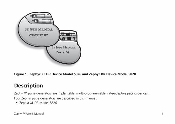
Figure 1. Zephyr XL DR Device Model 5826 and Zephyr DR Device Model 5820
DescriptionZephyr™ pulse generators are implantable, multi-programmable, rate-adaptive pacing devices.
Four Zephyr pulse generators are described in this manual:• Zephyr XL DR Model 5826
ZEPHYR™ XL DR
ZEPHYR™ DR
Zephyr™ User’s Manual 1
• Zephyr DR Model 5820• Zephyr XL SR Model 5626• Zephyr SR Model 5620.
Each model contains automatic rate-adjusting algorithms, patient safety features, and an extensive offer-ing of diagnostic tools and tests, including:• Instant Follow-Up features, including ACap™ Confirm, Ventricular AutoCapture™, signal amplitude
monitoring with trend, lead impedance monitoring with trend and autopolarity switch, and Instant Follow-Up EGMs, providing instant access to follow-up test results
• Maximum AF Suppression™ Rate, a programmable parameter that provides flexibility by allowing the physician to program the maximum sensor rate during exercise and a better tolerated AF Suppres-sion™ Rate during inactivity.
• Ventricular Intrinsic Preference (VIP™), which allows clinicians to program the value to increase the AV/PV Delay, as well as the search interval and the number of cycles to maintain the extended AV/PV prior to returning to the programmed AV/PV Delay. This flexibility promotes the patient's ventricular intrinsic rhythm.
• AF Suppression™ algorithm, a unique automatically adjusting pacing algorithm intended to suppress atrial arrhythmias1
• Advanced atrial arrhythmia diagnostics, including AT/AF Burden Trend and Event Counts, AT/AF Epi-sode Histogram and Log, and AF Suppression Histogram1
1. Not available in Models 5626 or 5620.
2 Description
• Stored Electrocardiograms, a record of real-time EGM waveform and Event Marker data of events pre-ceding and following a user-defined trigger
• Ventricular AutoCapture™, which automatically sets ventricular pulse amplitude, regularly adjusts the setting according to the patient’s measured capture threshold, and provides verification of ventricular capture on a beat-by-beat basis.
• ACap Confirm2, which automatically sets atrial pulse amplitude and regularly adjusts the setting according to the patient’s measured capture threshold. ACap Confirm also provides verification of atrial capture on a periodic basis.
• Rate Responsive Refractory Periods that adjust automatically according to the pacing rate• An Advanced Hysteresis Response that provides a means to periodically search for intrinsic rate and to
respond to a sudden drop in the intrinsic rate with user-programmable Intervention Rate and Duration• Atrial Protection Interval, designed to minimize atrial competitive pacing1
• Far-field Protection Interval, designed to reduce the incidence of far-field signal sensing in the atrium1
• The Omnisense™ accelerometer activity sensor which provides rate-modulated pacing.
In addition, with the Zephyr device, the Model 3510 Programming System and the Merlin™ Patient Care System (PCS) also offer:• On-screen Reference Manual• Removable media database interface• Continuous real-time printing of ECG, EGM, and Markers.
2. Available in Models 5826 and 5820 only.
Zephyr™ User’s Manual 3
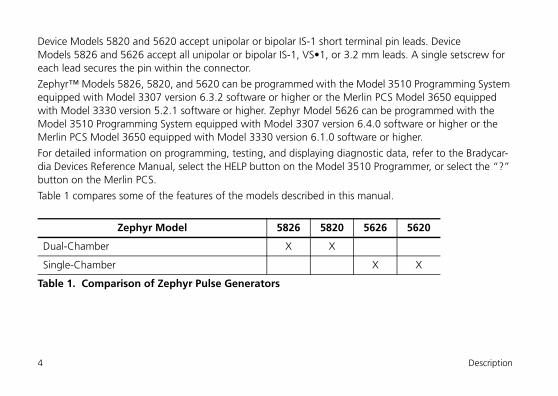
Device Models 5820 and 5620 accept unipolar or bipolar IS-1 short terminal pin leads. Device Models 5826 and 5626 accept all unipolar or bipolar IS-1, VS•1, or 3.2 mm leads. A single setscrew for each lead secures the pin within the connector.
Zephyr™ Models 5826, 5820, and 5620 can be programmed with the Model 3510 Programming System equipped with Model 3307 version 6.3.2 software or higher or the Merlin PCS Model 3650 equipped with Model 3330 version 5.2.1 software or higher. Zephyr Model 5626 can be programmed with the Model 3510 Programming System equipped with Model 3307 version 6.4.0 software or higher or the Merlin PCS Model 3650 equipped with Model 3330 version 6.1.0 software or higher.
For detailed information on programming, testing, and displaying diagnostic data, refer to the Bradycar-dia Devices Reference Manual, select the HELP button on the Model 3510 Programmer, or select the “?” button on the Merlin PCS.
Table 1 compares some of the features of the models described in this manual.
Zephyr Model 5826 5820 5626 5620
Dual-Chamber X X
Single-Chamber X X
Table 1. Comparison of Zephyr Pulse Generators
4 Description
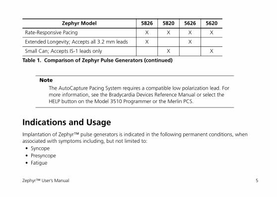
Indications and UsageImplantation of Zephyr™ pulse generators is indicated in the following permanent conditions, when associated with symptoms including, but not limited to:• Syncope• Presyncope• Fatigue
Rate-Responsive Pacing X X X X
Extended Longevity; Accepts all 3.2 mm leads X X
Small Can; Accepts IS-1 leads only X X
Note
The AutoCapture Pacing System requires a compatible low polarization lead. For more information, see the Bradycardia Devices Reference Manual or select the HELP button on the Model 3510 Programmer or the Merlin PCS.
Zephyr Model 5826 5820 5626 5620
Table 1. Comparison of Zephyr Pulse Generators (continued)
Zephyr™ User’s Manual 5
• Disorientation due to arrhythmia/bradycardia• Or any combination of those symptoms.
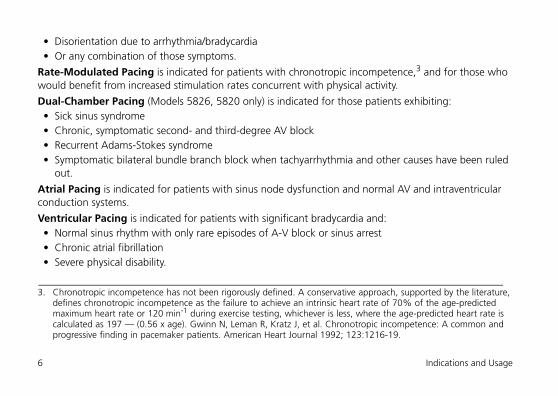
Rate-Modulated Pacing is indicated for patients with chronotropic incompetence,3 and for those who would benefit from increased stimulation rates concurrent with physical activity.
Dual-Chamber Pacing (Models 5826, 5820 only) is indicated for those patients exhibiting:• Sick sinus syndrome• Chronic, symptomatic second- and third-degree AV block• Recurrent Adams-Stokes syndrome• Symptomatic bilateral bundle branch block when tachyarrhythmia and other causes have been ruled
out.
Atrial Pacing is indicated for patients with sinus node dysfunction and normal AV and intraventricular conduction systems.
Ventricular Pacing is indicated for patients with significant bradycardia and:• Normal sinus rhythm with only rare episodes of A-V block or sinus arrest• Chronic atrial fibrillation• Severe physical disability.
3. Chronotropic incompetence has not been rigorously defined. A conservative approach, supported by the literature, defines chronotropic incompetence as the failure to achieve an intrinsic heart rate of 70% of the age-predicted maximum heart rate or 120 min-1 during exercise testing, whichever is less, where the age-predicted heart rate is calculated as 197 — (0.56 x age). Gwinn N, Leman R, Kratz J, et al. Chronotropic incompetence: A common and progressive finding in pacemaker patients. American Heart Journal 1992; 123:1216-19.
6 Indications and Usage
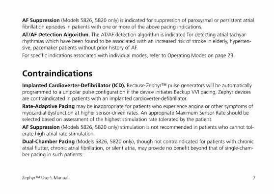
AF Suppression (Models 5826, 5820 only) is indicated for suppression of paroxysmal or persistent atrial fibrillation episodes in patients with one or more of the above pacing indications.
AT/AF Detection Algorithm. The AT/AF detection algorithm is indicated for detecting atrial tachyar-rhythmias which have been found to be associated with an increased risk of stroke in elderly, hyperten-sive, pacemaker patients without prior history of AF.
For specific indications associated with individual modes, refer to Operating Modes on page 23.
ContraindicationsImplanted Cardioverter-Defibrillator (ICD). Because Zephyr™ pulse generators will be automatically programmed to a unipolar pulse configuration if the device initiates Backup VVI pacing, Zephyr devices are contraindicated in patients with an implanted cardioverter-defibrillator.
Rate-Adaptive Pacing may be inappropriate for patients who experience angina or other symptoms of myocardial dysfunction at higher sensor-driven rates. An appropriate Maximum Sensor Rate should be selected based on assessment of the highest stimulation rate tolerated by the patient.
AF Suppression (Models 5826, 5820 only) stimulation is not recommended in patients who cannot tol-erate high atrial rate stimulation.
Dual-Chamber Pacing (Models 5826, 5820 only), though not contraindicated for patients with chronic atrial flutter, chronic atrial fibrillation, or silent atria, may provide no benefit beyond that of single-cham-ber pacing in such patients.
Zephyr™ User’s Manual 7
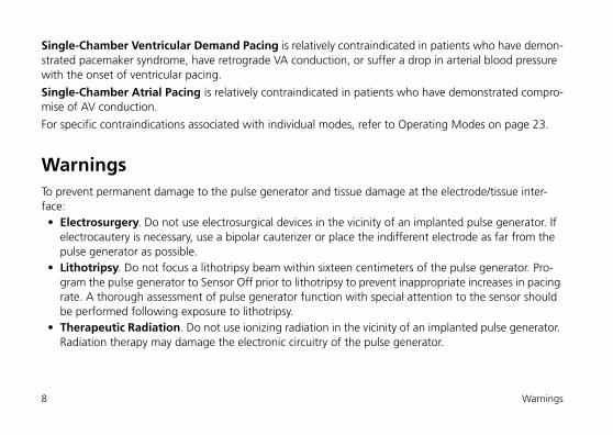
Single-Chamber Ventricular Demand Pacing is relatively contraindicated in patients who have demon-strated pacemaker syndrome, have retrograde VA conduction, or suffer a drop in arterial blood pressure with the onset of ventricular pacing.
Single-Chamber Atrial Pacing is relatively contraindicated in patients who have demonstrated compro-mise of AV conduction.
For specific contraindications associated with individual modes, refer to Operating Modes on page 23.
WarningsTo prevent permanent damage to the pulse generator and tissue damage at the electrode/tissue inter-face:• Electrosurgery. Do not use electrosurgical devices in the vicinity of an implanted pulse generator. If
electrocautery is necessary, use a bipolar cauterizer or place the indifferent electrode as far from the pulse generator as possible.
• Lithotripsy. Do not focus a lithotripsy beam within sixteen centimeters of the pulse generator. Pro-gram the pulse generator to Sensor Off prior to lithotripsy to prevent inappropriate increases in pacing rate. A thorough assessment of pulse generator function with special attention to the sensor should be performed following exposure to lithotripsy.
• Therapeutic Radiation. Do not use ionizing radiation in the vicinity of an implanted pulse generator. Radiation therapy may damage the electronic circuitry of the pulse generator.
8 Warnings
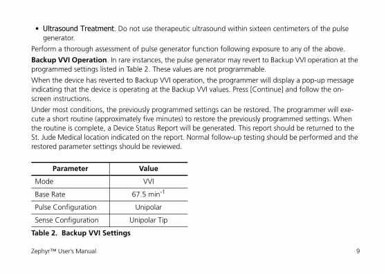
• Ultrasound Treatment. Do not use therapeutic ultrasound within sixteen centimeters of the pulse generator.
Perform a thorough assessment of pulse generator function following exposure to any of the above.
Backup VVI Operation. In rare instances, the pulse generator may revert to Backup VVI operation at the programmed settings listed in Table 2. These values are not programmable.
When the device has reverted to Backup VVI operation, the programmer will display a pop-up message indicating that the device is operating at the Backup VVI values. Press [Continue] and follow the on-screen instructions.
Under most conditions, the previously programmed settings can be restored. The programmer will exe-cute a short routine (approximately five minutes) to restore the previously programmed settings. When the routine is complete, a Device Status Report will be generated. This report should be returned to the St. Jude Medical location indicated on the report. Normal follow-up testing should be performed and the restored parameter settings should be reviewed.
Parameter Value
Mode VVI
Base Rate 67.5 min-1
Pulse Configuration Unipolar
Sense Configuration Unipolar Tip
Table 2. Backup VVI Settings
Zephyr™ User’s Manual 9
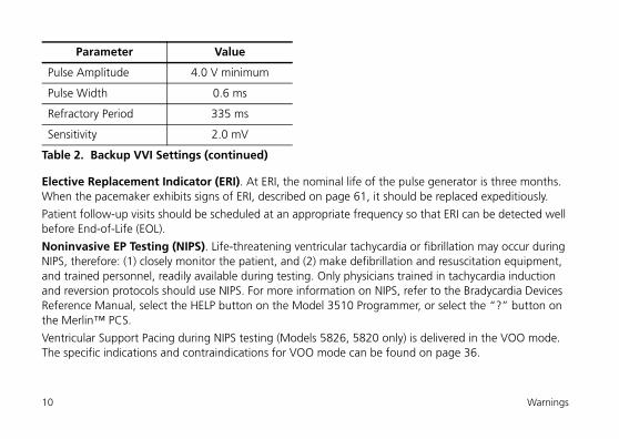
Elective Replacement Indicator (ERI). At ERI, the nominal life of the pulse generator is three months. When the pacemaker exhibits signs of ERI, described on page 61, it should be replaced expeditiously.
Patient follow-up visits should be scheduled at an appropriate frequency so that ERI can be detected well before End-of-Life (EOL).
Noninvasive EP Testing (NIPS). Life-threatening ventricular tachycardia or fibrillation may occur during NIPS, therefore: (1) closely monitor the patient, and (2) make defibrillation and resuscitation equipment, and trained personnel, readily available during testing. Only physicians trained in tachycardia induction and reversion protocols should use NIPS. For more information on NIPS, refer to the Bradycardia Devices Reference Manual, select the HELP button on the Model 3510 Programmer, or select the “?” button on the Merlin™ PCS.
Ventricular Support Pacing during NIPS testing (Models 5826, 5820 only) is delivered in the VOO mode. The specific indications and contraindications for VOO mode can be found on page 36.
Pulse Amplitude 4.0 V minimum
Pulse Width 0.6 ms
Refractory Period 335 ms
Sensitivity 2.0 mV
Parameter Value
Table 2. Backup VVI Settings (continued)
10 Warnings
Precautions• For single use only.
Sterilization• The package contents have been sterilized with ethylene oxide before shipment. This device is for sin-
gle use only and is not intended to be resterilized.• If the sterile package has been compromised, contact St. Jude Medical.
Storage and Handling• Mechanical Shock. St. Jude Medical™ pulse generators are ruggedly constructed. However, if you
suspect the pulse generator has been damaged, do not implant it; return it to St. Jude Medical.• Temperature. Do not subject the pulse generator to temperatures above 50° C (122° F) or below –
5° C (23° F). Exposure to temperatures below 0° C may cause false ERI indications. Following expo-sure to extreme temperatures, warm the device to room temperature. If ERI indications are still pres-ent, return the pulse generator to St. Jude Medical.
• Incineration. Do not incinerate the pulse generator.
Preparation for Implantation• Package Label. Before opening the sterile package, carefully read the label and verify that the pack-
age contains the desired pulse generator.
Zephyr™ User’s Manual 11
• Verifying Operation. Before opening the sterile package, verify that the pulse generator is operating properly by interrogating it in the package. Remove the magnet and position the telemetry wand over the package and select “Interrogate.” Then, select the “Meas. Data/Diagnostics” tab. The unit’s Mea-sured Data should indicate normal voltage and battery status, and the programmed parameters should be identical to the Shipped Settings listed on the package label and in Table 12 on page 67 and Table 13 on page 73.
• Package Integrity. Ensure that the package has not been opened or in any way compromised. If damage is suspected, return it to the manufacturer.
• “Use Before” Date. Do not implant the pulse generator after the “use before” date printed on the label.
12 Precautions

Figure 2. Opening the Sterile Package
Outside sterile field
Inside sterile field
Zephyr™ User’s Manual 13
• Opening the Package. If interrogation of the device in its sterile packaging indicates normal func-tioning, remove it from the package. The package’s outer tray can be opened in nonsterile surround-ings. However, when opening the inner tray, complete sterile technique must be observed (Figure 2).
Pre-Implant Testing• Pacing System Analyzer. Before implantation, the clinician may wish to test the device using a com-
patible pacing system analyzer (PSA) with calibrated sensitivity and output settings. When the probe is attached to the pulse generator’s connector, the programmed parameters should be identical to the Shipped Settings listed on the package label and in Table 12 on page 67 (for dual-chamber devices) and Table 13 on page 73 (for single-chamber devices).
• Adaptor Probes. Use only IS-1 PSA cable adaptor probes when testing the pulse generator. Other probes may damage the connector.
• Compatible Pacing Leads. Zephyr™ Models 5820 and 5620 accept unipolar or bipolar IS-1 short terminal pin leads. Zephyr XL Models 5826 and 5626 accept all unipolar or bipolar IS-1, VS•1, or 3.2 mm leads. Prior to implantation, make sure the leads fit easily and snugly into the pulse genera-tor’s header.
• Capture/Sensing Thresholds. Capture and sensing thresholds should be determined with a PSA before implanting the pulse generator. Connect the negative (black) PSA terminal to the portion of the lead terminal pin corresponding to the tip electrode. The positive (red) terminal should be con-
14 Pre-Implant Testing
nected to the ring electrode portion of the lead pin for bipolar leads or to an indifferent electrode. For more information on conducting capture and sensing threshold tests, please consult the PSA techni-cal manual.
Implantation• Case Markings. Examine the markings on the pulse generator case and verify proper atrial and ven-
tricular connection.• Setscrew. Exercise caution when turning the setscrew, which may be backed out of the connector if
turned counter-clockwise for more than two rotations.
Programming• Programmer. Zephyr™ Models 5826, 5820, and 5620 can be interrogated and programmed with
the Model 3510 programmer equipped with Model 3307 version 6.3.2 software or higher or the Merlin™ PCS Model 3650 equipped with Model 3330 version 5.2.1 software or higher. Zephyr Model 5626 can be interrogated and programmed with the Model 3510 programmer equipped with Model 3307 version 6.4.0 software or higher or the Merlin™ PCS Model 3650 equipped with Model 3330 version 6.1.0 software or higher.For a list of programmable parameters and their programmable values, see Table 12 on page 67 (for dual-chamber devices) and Table 13 on page 73 (for single chamber devices).
• Setting Lead Type. When the user interrogates the device for the first time, the programmer will prompt the user to set the Lead Type. Because some parameters are determined by the Lead Type (for example, Pulse Configuration), the user should set this parameter when the device is implanted.
Zephyr™ User’s Manual 15
• Emergency VVI. When programming the device to Emergency VVI settings, press the programmer’s Emergency VVI button only once. Settings for Emergency VVI can be found in the Bradycardia Devices Reference Manual, by selecting the HELP button on the Model 3510 Programmer, or by selecting the “?” button on the Merlin PCS.
• ODO, OVO, and OAO Modes are not recommended for patients who would be adversely affected by even a short cessation of device function.
• Pulse Amplitude. If the AutoCapture™ Pacing System is not in use, or if the lead is implanted in the atrium, determine the capture threshold before programming the Pulse Amplitude. Program Pulse Amplitude to yield a suitable safety margin for reliable, long-term capture. Reassess capture thresh-olds periodically.
• High-Output Settings. Programming high-output settings or a high Base Rate may shorten the time to ERI.
• Runaway Protection. Hardware circuitry in the pulse generator prevents the device from stimulating at rates higher than 190 min-1 (± 10 min-1).
• ACap™ Confirm4. Before setting ACap Confirm On, ensure that the system is compatible by con-ducting an ACap Confirm Setup Test4.
• Ventricular AutoCapture. Before setting Ventricular AutoCapture On, ensure that the system is compatible by conducting a Ventricular AutoCapture Setup Test.
• Sensitivity Settings. Careful consideration should be given to patient exposure to electromagnetic interference if programming sensitivity greater than 0.3 mV with a bipolar sense configuration setting and 2.0 mV with a unipolar sense configuration setting.
4. Available in Models 5826 and 5820 only.
16 Pre-Implant Testing
Environmental and Medical Therapy HazardsSt. Jude Medical™ pulse generators are equipped with special shielding and filters which significantly reduce the adverse effects of electromagnetic interference (EMI) on the operation of the device.
Patients should be directed to exercise reasonable caution in avoidance of strong electric or magnetic fields. If the device inhibits or reverts to asynchronous operation while in the presence of electromagnetic interference (EMI), the patient should move away from the EMI source or turn the source off.
Advise patients to seek medical guidance before entering environments which could adversely affect the operation of the pulse generator, including areas protected by a warning notice preventing entry by pace-maker patients.
Medical Procedures and EnvironmentsIn general, pacemaker patients should not be exposed to hospital equipment that produces high electro-magnetic field strength signals, such as diathermy machines and electrosurgical units.• CT Scans. CT scans, due to their increased power levels and long exposure times, have the remote
possibility of interfering with implanted devices. The potential interference is transient and occurs only when the X-ray signal is present. Continuous exposure may cause a temporary sensor rate increase. In addition, there is a remote possibility for a device to intermittently oversense while the CT scanning beam is directly over the implanted device.
• External Defibrillation. The electronic circuitry in the pulse generator provides protection from defi-brillation discharges. Nevertheless, do not place defibrillator paddles directly over the pulse generator or pacing lead. Following defibrillation, ensure that the pacemaker is operating correctly.
Zephyr™ User’s Manual 17
• Magnetic Resonance Imaging (MRI). MRI for patients with implantable pulse generators has been contraindicated by MRI manufacturers. Clinicians should carefully weigh the decisions to use MRI with pacemaker patients. Additional safety concerns include: - Magnetic and RF fields produced by MRI may increase pacing rate, inhibit pacing, cause asynchro-
nous pacing or result in pacing at random rates- MRI may result in changes in capture thresholds due to heating of pacing leads in any patient- MRI may irreversibly damage the pulse generator- Patients should be closely monitored during the MRI- Assess the pulse generator function before and after exposure to MRI.
• Ionizing Radiation. Therapeutic ionizing radiation (for example, used in linear accelerators and cobalt machines) can permanently damage the pulse generator’s circuitry. The effect of ionizing radia-tion is cumulative; the potential for damage to the pulse generator is proportional to the patient’s total radiation dosage. If the patient must be exposed to ionizing radiation, protect the pulse genera-tor during the procedure with local radiation shielding. If tissue near the implant site must be irradi-ated, it may be necessary to move the pulse generator to another area. Before and after exposure to radiation, evaluate the pulse generator operation to identify any adverse consequences.
• Transcutaneous Electrical Nerve Stimulation (TENS). To reduce the possibility of interference with pacemaker function, place the TENS electrodes close to one another and as far from the pulse gener-ator as possible. Before allowing unrestricted use of TENS in a home or other setting, screen the patient in a monitored environment for possible interaction.
• Therapeutic Diathermy. Avoid diathermy, even if the device is programmed off, as it may damage tissue around the implanted electrodes or may permanently damage the pulse generator.
18 Pre-Implant Testing
• Electrosurgical Cautery can induce ventricular arrhythmias and/or fibrillation or may cause asyn-chronous or inhibited pulse generator operation. If use of electrocautery is necessary, the current path and ground plate should be kept as far away from the pulse generator and leads as possible. A bipo-lar cauterizer may minimize these effects. Following electrocautery, conduct a thorough assessment of the pulse generator.
Patient Environment• High-Voltage transmission lines and equipment, arc or resistance welders, induction furnaces, and
similar equipment may generate substantial EMI fields that may interfere with device operation.• Communication Equipment, such as microwave transmitters,5 linear power amplifiers, or high-
power amateur transmitters may generate sufficient EMI to interfere with the operation of the pulse generator. Advise patients to move away from this equipment to resume normal pacemaker opera-tion.
• Home Appliances that are in good working order and properly grounded do not usually produce enough EMI to interfere with device operation. Electric vibrators, razors, and handtools held directly over the device may disturb its operation.
• Twiddler’s Syndrome. Caution patients against manipulating the implanted pulse generator since it may result in lead damage or lead displacement.
5. Home appliance microwave ovens do not interfere with pulse generator operation.
Zephyr™ User’s Manual 19
• Patient Activities. Any activities that involve repetitive impacts or jarring (such as horseback riding, jackhammer use, etc.) may increase the pacing rate when the pulse generator’s Sensor is pro-grammed On. Caution patients against such activity and program Sensor parameters with these activ-ities in mind.
• Theft Detection Systems. Theft detection systems, such as those often located at the entrances and exits of stores and public libraries may disturb pacemaker function only if the patient pauses in the path of the beam.
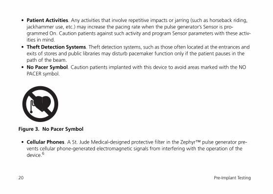
• No Pacer Symbol. Caution patients implanted with this device to avoid areas marked with the NO PACER symbol.
Figure 3. No Pacer Symbol
• Cellular Phones. A St. Jude Medical-designed protective filter in the Zephyr™ pulse generator pre-vents cellular phone-generated electromagnetic signals from interfering with the operation of the device.6
20 Pre-Implant Testing
The device has also been tested for compatibility with handheld wireless transmitters in accordance with the requirements of AAMI PC69. This testing covered the operating frequencies (450 MHz - 3 GHz) and pulsed modulation techniques of all of the digital cellular phone technologies in worldwide use today. For more information, you or your patient may wish to contact Technical Support (page 101).
Explantation• Do not reuse explanted pulse generators and leads.• Clean explanted equipment with +1% sodium hypochlorite, rinse with water, dry.• Return the explanted device to the manufacturer.• Explant the pulse generator before cremation of a deceased patient.• Hex wrenches are available for disconnecting a previously implanted pulse generator from the
indwelling leads. To obtain the wrenches, contact your local St. Jude Medical representative.
Potential Adverse EventsThe following are potential complications associated with the use of any pacing system:• Arrhythmia• Heart block
6. Carrillo R, Williams DB, Traad EA, Schor JS. Electromagnetic filters impeded adverse interference of pacemakers by digital cellular telephones. JACC 1996; 27(2A):15A Abstract 901-22.
Zephyr™ User’s Manual 21
• Thrombosis• Threshold elevation• Valve damage• Pneumothorax• Myopotential sensing• Vessel damage• Air embolism• Body rejection phenomena• Cardiac tamponade or perforation• Formation of fibrotic tissue; local tissue reaction• Inability to interrogate or program a pulse generator because of programmer malfunction• Infection• Interruption of desired pulse generator function due to electrical interference• Loss of desired pacing and/or sensing due to lead displacement, body reaction at electrode interface,
or lead malfunction (fracture or damage to insulation)• Loss of normal pacemaker function due to battery failure or component malfunction• Pacemaker migration, pocket erosion, or hematoma• Pectoral muscle stimulation• Phrenic nerve or diaphragmatic stimulation.
22 Potential Adverse Events
The following, in addition to the above, are potential complications associated with the use of rate-mod-ulated pacing systems:• Inappropriate, rapid pacing rates due to sensor failure or to the detection of signals other than patient
activity• Loss of activity-response due to sensor failure• Palpitations with high-rate pacing.
Operating ModesZephyr™ device Models 5826 and 5820 are dual-chamber devices that may be programmed to various pacing therapy modes, depending upon the chamber to be paced. Zephyr device Models 5626 and 5620 are single-chamber devices that may be programmed only to single-chamber modes.
Dual-Chamber ModesDDD
(Dual-Chamber Stimulation, Sensing, and Inhibition; Atrial Tracking)
DDD mode allows pacing and sensing in both chambers; intrinsic activity inhibits the output in the respec-tive chamber and intrinsic atrial events are tracked in the ventricle. In the absence of intrinsic activity, both chambers are paced at the programmed Base Rate and AV Delay (Figure 4).
Zephyr™ User’s Manual 23
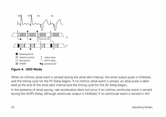
Figure 4. DDD Mode
When an intrinsic atrial event is sensed during the atrial alert interval, the atrial output pulse is inhibited, and the timing cycle for the PV Delay begins. If no intrinsic atrial event is sensed, an atrial pulse is deliv-ered at the end of the atrial alert interval and the timing cycle for the AV Delay begins.
In the presence of atrial pacing, rate acceleration does not occur if an intrinsic ventricular event is sensed during the AV/PV Delay, although ventricular output is inhibited. If no ventricular event is sensed in AV/
refractory period
blanking period
alert period AV/PV delay
output pulse
sensed eventPVARP
A
V
programmed rate
AR PR PV AV
24 Operating Modes
PV Delay, it times out, a ventricular pulse is delivered, and the timing cycle for the atrial escape interval (AEI) begins.
Intrinsic ventricular activity sensed during the ventricular alert period will inhibit both atrial and ventricular output pulses and recycle the timing cycles on both channels to the beginning of the atrial alert interval.
Indications. DDD pacing is indicated in the presence of AV conduction disorders with normal or abnor-mal sinus node function.
Contraindications. DDD pacing is contraindicated in the presence of frequent or persistent atrial tachyarrhythmias or silent atria. However, the device’s Auto Mode Switch feature can automatically switch the device to DDI pacing in the presence of atrial tachyarrhythmias. Intact retrograde conduction,
NoteIn the Zephyr™ device, at least 125 ms of the V-A interval is designated as a guar-anteed atrial alert period in order to minimize competitive atrial pacing.
NoteIn DDDR mode, during activity and at rates below the Maximum Tracking Rate, the device’s A-A interval is adjusted to reflect the sensor-indicated stimulation rate determined for each cycle.
Zephyr™ User’s Manual 25
though not a contraindication, requires the careful programming of an appropriate Post Ventricular Atrial Refractory Period (PVARP) value.
DDI
(Dual-Chamber Stimulation; Dual-Chamber Sensing and Inhibition; No Atrial Tracking)
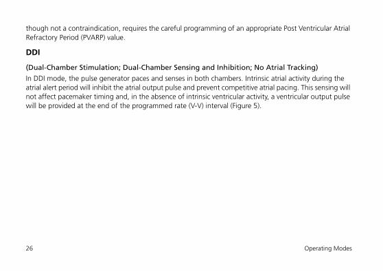
In DDI mode, the pulse generator paces and senses in both chambers. Intrinsic atrial activity during the atrial alert period will inhibit the atrial output pulse and prevent competitive atrial pacing. This sensing will not affect pacemaker timing and, in the absence of intrinsic ventricular activity, a ventricular output pulse will be provided at the end of the programmed rate (V-V) interval (Figure 5).
26 Operating Modes
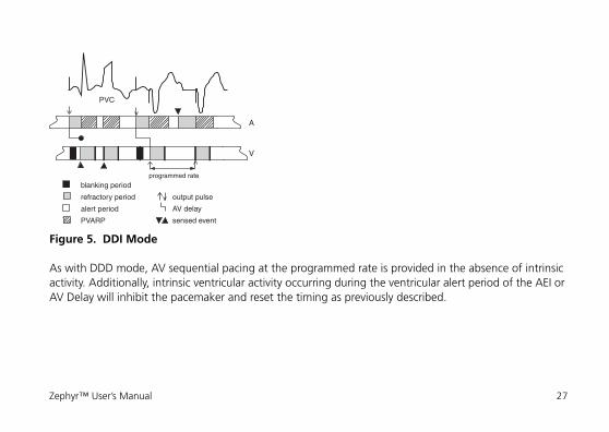
Figure 5. DDI Mode
As with DDD mode, AV sequential pacing at the programmed rate is provided in the absence of intrinsic activity. Additionally, intrinsic ventricular activity occurring during the ventricular alert period of the AEI or AV Delay will inhibit the pacemaker and reset the timing as previously described.
refractory period
blanking period
alert period AV delay
output pulse
sensed eventPVARP
A
V
programmed rate
PVC
Zephyr™ User’s Manual 27
Indications. DDI pacing is indicated in situations where dual-chamber pacing is required, the avoidance of competitive atrial pacing is desired, and there is a specific reason that atrial tracking is not required or desired (such as intermittent atrial tachyarrhythmia in the presence of intact AV nodal conduction).
Contraindications. DDI pacing is contraindicated in high-grade AV block with normal sinus node func-tion, chronic atrial fibrillation or flutter, and silent atria.
DVI
(Dual-Chamber Stimulation; Ventricular Sensing and Inhibition)
DVI mode paces both chambers but senses only in the ventricle. In the absence of intrinsic ventricular activity, both chambers are paced at the programmed Base Rate and AV Delay. When a ventricular event is detected during the ventricular alert period, all pulse generator output is inhibited and the timing cycle of the AEI is restarted. If no intrinsic ventricular event is sensed during the AEI or AV Delay, the AEI times out, and an atrial output pulse is delivered (Figure 6).
A native ventricular event during either the AEI or the AV Delay will inhibit the ventricular output and reset the timing cycle of the AEI. If no sensed ventricular event occurs within the AV Delay, it times out, at which point a ventricular output is delivered.
NoteIn the Zephyr device, at least 125 ms of the V-A interval is designated as a guar-anteed atrial alert period in order to minimize competitive atrial pacing.
28 Operating Modes
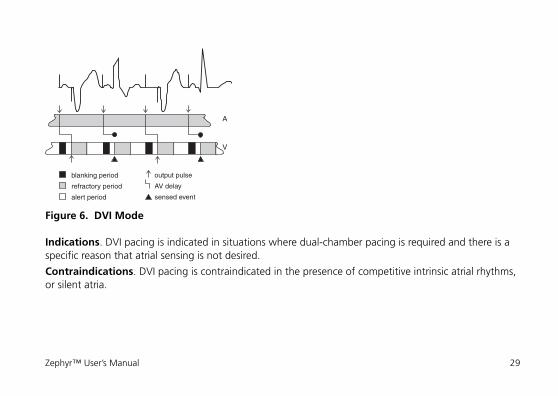
Figure 6. DVI Mode
Indications. DVI pacing is indicated in situations where dual-chamber pacing is required and there is a specific reason that atrial sensing is not desired.
Contraindications. DVI pacing is contraindicated in the presence of competitive intrinsic atrial rhythms, or silent atria.
A
V
refractory period AV delay
blanking period
alert period
output pulse
sensed event
Zephyr™ User’s Manual 29
DOO
(Dual-Chamber Asynchronous Pacing)
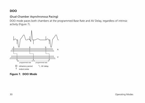
DOO mode paces both chambers at the programmed Base Rate and AV Delay, regardless of intrinsic activity (Figure 7).
Figure 7. DOO Mode
A
V
programmed rate programmed rate
refractory period AV delay
output pulse
30 Operating Modes
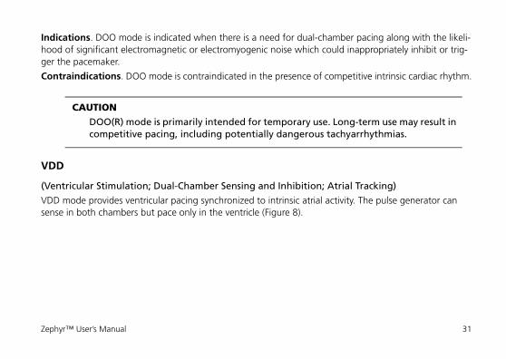
Indications. DOO mode is indicated when there is a need for dual-chamber pacing along with the likeli-hood of significant electromagnetic or electromyogenic noise which could inappropriately inhibit or trig-ger the pacemaker.
Contraindications. DOO mode is contraindicated in the presence of competitive intrinsic cardiac rhythm.
VDD
(Ventricular Stimulation; Dual-Chamber Sensing and Inhibition; Atrial Tracking)
VDD mode provides ventricular pacing synchronized to intrinsic atrial activity. The pulse generator can sense in both chambers but pace only in the ventricle (Figure 8).
CAUTIONDOO(R) mode is primarily intended for temporary use. Long-term use may result in competitive pacing, including potentially dangerous tachyarrhythmias.
Zephyr™ User’s Manual 31
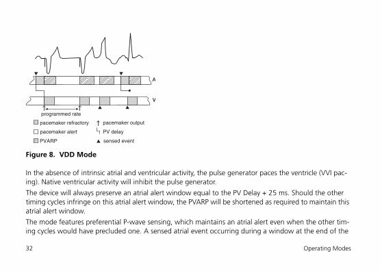
Figure 8. VDD Mode
In the absence of intrinsic atrial and ventricular activity, the pulse generator paces the ventricle (VVI pac-ing). Native ventricular activity will inhibit the pulse generator.
The device will always preserve an atrial alert window equal to the PV Delay + 25 ms. Should the other timing cycles infringe on this atrial alert window, the PVARP will be shortened as required to maintain this atrial alert window.
The mode features preferential P-wave sensing, which maintains an atrial alert even when the other tim-ing cycles would have precluded one. A sensed atrial event occurring during a window at the end of the
V
PV delay
pacemaker refractory
pacemaker alert
pacemaker output
A
sensed event
programmed rate
PVARP
32 Operating Modes
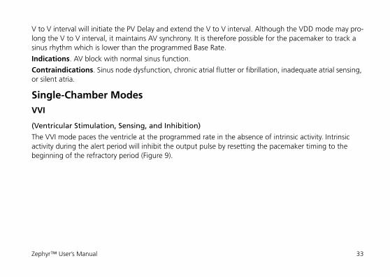
V to V interval will initiate the PV Delay and extend the V to V interval. Although the VDD mode may pro-long the V to V interval, it maintains AV synchrony. It is therefore possible for the pacemaker to track a sinus rhythm which is lower than the programmed Base Rate.
Indications. AV block with normal sinus function.
Contraindications. Sinus node dysfunction, chronic atrial flutter or fibrillation, inadequate atrial sensing, or silent atria.
Single-Chamber ModesVVI
(Ventricular Stimulation, Sensing, and Inhibition)
The VVI mode paces the ventricle at the programmed rate in the absence of intrinsic activity. Intrinsic activity during the alert period will inhibit the output pulse by resetting the pacemaker timing to the beginning of the refractory period (Figure 9).
Zephyr™ User’s Manual 33
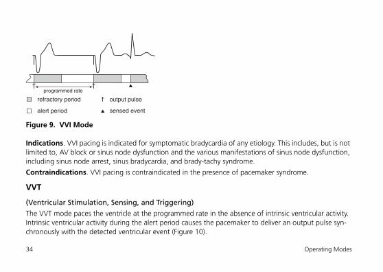
Figure 9. VVI Mode
Indications. VVI pacing is indicated for symptomatic bradycardia of any etiology. This includes, but is not limited to, AV block or sinus node dysfunction and the various manifestations of sinus node dysfunction, including sinus node arrest, sinus bradycardia, and brady-tachy syndrome.
Contraindications. VVI pacing is contraindicated in the presence of pacemaker syndrome.
VVT
(Ventricular Stimulation, Sensing, and Triggering)
The VVT mode paces the ventricle at the programmed rate in the absence of intrinsic ventricular activity. Intrinsic ventricular activity during the alert period causes the pacemaker to deliver an output pulse syn-chronously with the detected ventricular event (Figure 10).
output pulserefractory period
alert period
programmed rate
sensed event
34 Operating Modes
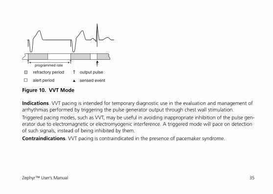
Figure 10. VVT Mode
Indications. VVT pacing is intended for temporary diagnostic use in the evaluation and management of arrhythmias performed by triggering the pulse generator output through chest wall stimulation.
Triggered pacing modes, such as VVT, may be useful in avoiding inappropriate inhibition of the pulse gen-erator due to electromagnetic or electromyogenic interference. A triggered mode will pace on detection of such signals, instead of being inhibited by them.
Contraindications. VVT pacing is contraindicated in the presence of pacemaker syndrome.
output pulserefractory period
alert period
programmed rate
sensed event
Zephyr™ User’s Manual 35
VOO
(Ventricular Asynchronous Pacing)
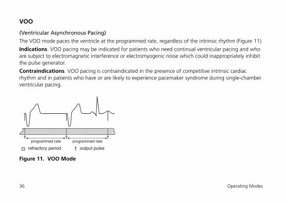
The VOO mode paces the ventricle at the programmed rate, regardless of the intrinsic rhythm (Figure 11).
Indications. VOO pacing may be indicated for patients who need continual ventricular pacing and who are subject to electromagnetic interference or electromyogenic noise which could inappropriately inhibit the pulse generator.
Contraindications. VOO pacing is contraindicated in the presence of competitive intrinsic cardiac rhythm and in patients who have or are likely to experience pacemaker syndrome during single-chamber ventricular pacing.
Figure 11. VOO Mode
output pulserefractory period
programmed rate programmed rate
36 Operating Modes
AAI
(Atrial Stimulation, Sensing, and Inhibition)
The AAI mode paces the atrium at the programmed rate in the absence of intrinsic atrial activity. Intrinsic atrial activity during the alert period will inhibit the output pulse and reset pacemaker timing to the beginning of the refractory period (Figure 12).
CAUTIONVOO(R) mode is primarily intended for temporary use. Long-term use may result in competitive pacing, inducing potentially dangerous ventricular tachyarrhythmias.
Zephyr™ User’s Manual 37
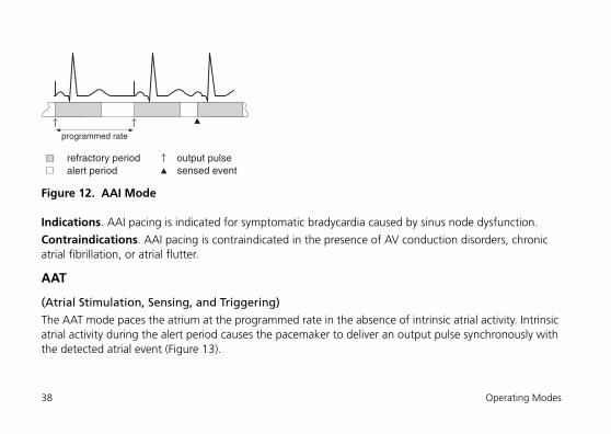
Figure 12. AAI Mode
Indications. AAI pacing is indicated for symptomatic bradycardia caused by sinus node dysfunction.
Contraindications. AAI pacing is contraindicated in the presence of AV conduction disorders, chronic atrial fibrillation, or atrial flutter.
AAT
(Atrial Stimulation, Sensing, and Triggering)
The AAT mode paces the atrium at the programmed rate in the absence of intrinsic atrial activity. Intrinsic atrial activity during the alert period causes the pacemaker to deliver an output pulse synchronously with the detected atrial event (Figure 13).
output pulserefractory periodalert period
programmed rate
sensed event
38 Operating Modes
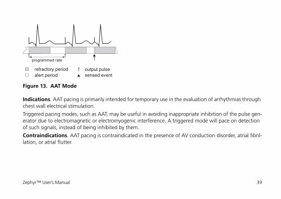
Figure 13. AAT Mode
Indications. AAT pacing is primarily intended for temporary use in the evaluation of arrhythmias through chest wall electrical stimulation.
Triggered pacing modes, such as AAT, may be useful in avoiding inappropriate inhibition of the pulse gen-erator due to electromagnetic or electromyogenic interference. A triggered mode will pace on detection of such signals, instead of being inhibited by them.
Contraindications. AAT pacing is contraindicated in the presence of AV conduction disorder, atrial fibril-lation, or atrial flutter.
output pulserefractory periodalert period
programmed rate
sensed event
Zephyr™ User’s Manual 39
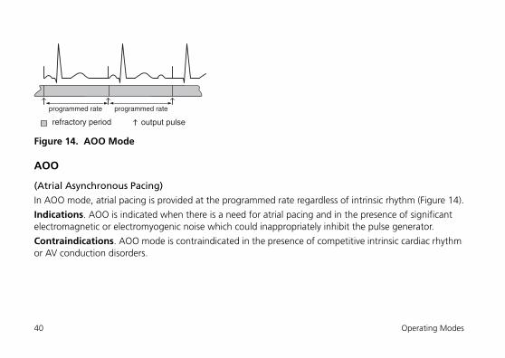
Figure 14. AOO Mode
AOO
(Atrial Asynchronous Pacing)
In AOO mode, atrial pacing is provided at the programmed rate regardless of intrinsic rhythm (Figure 14).
Indications. AOO is indicated when there is a need for atrial pacing and in the presence of significant electromagnetic or electromyogenic noise which could inappropriately inhibit the pulse generator.
Contraindications. AOO mode is contraindicated in the presence of competitive intrinsic cardiac rhythm or AV conduction disorders.
refractory period
programmed rate programmed rate
output pulse
40 Operating Modes
ODO, OVO, and OAO ModesIn these modes, pacing is turned off while the device continues to sense intrinsic activity and record the events in the pulse generator memory. These modes are useful primarily for temporary diagnostic evalua-tion of underlying rhythm and when a record of the activity is needed. However, when these modes are programmed, the Model 3510 programmer and the Merlin PCS do not display Event Markers or mea-sured heart rate.
These modes are not available when Sensor is programmed On, and the Sensor cannot be programmed On when these modes are programmed.
As with all modes, programming a different mode will clear diagnostic data.
CAUTIONAOO(R) mode is intended for temporary use. Long-term use may result in compet-itive pacing in the atrium.
CAUTIONODO, OVO, or OAO modes are not recommended for pacemaker-dependent patients or patients who might be affected by even a short cessation of the device’s operation.
Zephyr™ User’s Manual 41
Rate-Modulated ModesThe function of rate-modulated modes (Sensor On) is to alter the pacing rate to match activity changes in accordance with programmed parameters. Rate-response can be enabled with any pacing mode.
Indications. These are the same as modes without rate modulation, except that rate-modulated modes are further indicated when an increase in pacing rate with activity is desired.
Contraindications. These are the same as modes without rate modulation, except that rate-modulated modes are also contraindicated when pacing rates above the programmed Base Rate may not be well tol-erated.
Programming GuidelinesGeneralZephyr™ Models 5826, 5820, and 5620 can be programmed using the 3510 programmer equipped with Model 3307, version 6.3.2 software or higher or the Merlin™ PCS Model 3650 equipped with Model 3330 version 5.2.1 software or higher. Zephyr Model 5626 can be programmed using the 3510 program-mer equipped with Model 3307, version 6.4.0 software or higher or the Merlin™ PCS Model 3650 equipped with Model 3330 version 6.1.0 or higher.
For detailed information on the programmer, consult the Bradycardia Devices Reference Manual, select the HELP button on the Model 3510 Programmer, or select the “?” button on the Merlin PCS. For a list of all programmable parameters and settings, see Table 14 on page 76 (for dual-chamber devices) and Table 15 on page 83 (for single chamber devices).
42 Programming Guidelines

Magnet UseTo interrogate the device, remove the magnet from the programmer telemetry wand. A magnet will inter-fere with proper telemetry.
Temporary ProgrammingZephyr™ pulse generators feature Temporary Programming to aid the clinician in diagnosing and treating the patient. The clinician can temporarily program parameters to assess their effects with the ability to quickly cancel or permanently program the setting. For more information, consult the Bradycardia Devices Reference Manual, select the HELP button on the Model 3510 Programmer, or select the “?” button on the Merlin™ PCS.
Preset Programmed SettingsShipped SettingsThe device’s parameter settings are preset when the device is manufactured. These settings can be found in Table 12 on page 67 (for dual-chamber devices) and Table 13 on page 73 (for single-chamber devices).
Emergency SettingsThe device is equipped with standard, high-output settings that can be quickly programmed using the programmer’s Emergency VVI function. Settings for Emergency VVI can be found in the Bradycardia Devices Reference Manual, by selecting the HELP button on the Model 3510 Programmer, or by selecting the “?” button on the Merlin PCS.
Zephyr™ User’s Manual 43
Diagnostic Data, Tests and ToolsZephyr™ pulse generators collect and retain a variety of diagnostic data that can be viewed and printed with the Model 3510 programmer or the Merlin PCS. These include:• Instant Follow-Up measurements, which are available automatically upon device interrogation:
- Ventricular AutoCapture trends and EGMs- ACap™ Confirm trends and EGMs7
- P- and R-wave trends and EGMs- Lead impedance trends
• FastPath Summary Screen• AT/AF Burden Trend and Event Counts7
• AF Suppression Histogram and Event Counts7
• AT/AF Episode Histogram and Log7
NoteWhen Emergency VVI is selected, diagnostic data are cleared from memory with-out a warning.
7. Not available in Models 5626 or 5620.
44 Diagnostic Data, Tests and Tools
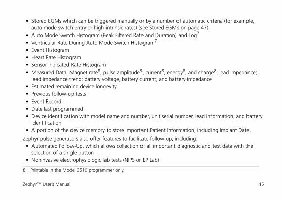
• Stored EGMs which can be triggered manually or by a number of automatic criteria (for example, auto mode switch entry or high intrinsic rates) (see Stored EGMs on page 47)
• Auto Mode Switch Histogram (Peak Filtered Rate and Duration) and Log7
• Ventricular Rate During Auto Mode Switch Histogram7
• Event Histogram• Heart Rate Histogram• Sensor-indicated Rate Histogram• Measured Data: Magnet rate8; pulse amplitude8, current8, energy8, and charge8; lead impedance;
lead impedance trend; battery voltage, battery current, and battery impedance• Estimated remaining device longevity• Previous follow-up tests• Event Record• Date last programmed• Device identification with model name and number, unit serial number, lead information, and battery
identification• A portion of the device memory to store important Patient Information, including Implant Date.
Zephyr pulse generators also offer features to facilitate follow-up, including:• Automated Follow-Up, which allows collection of all important diagnostic and test data with the
selection of a single button• Noninvasive electrophysiologic lab tests (NIPS or EP Lab)
8. Printable in the Model 3510 programmer only.
Zephyr™ User’s Manual 45
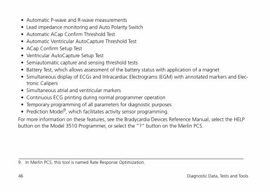
• Automatic P-wave and R-wave measurements• Lead impedance monitoring and Auto Polarity Switch• Automatic ACap Confirm Threshold Test• Automatic Ventricular AutoCapture Threshold Test• ACap Confirm Setup Test• Ventricular AutoCapture Setup Test• Semiautomatic capture and sensing threshold tests• Battery Test, which allows assessment of the battery status with application of a magnet• Simultaneous display of ECGs and Intracardiac Electrograms (EGM) with annotated markers and Elec-
tronic Calipers• Simultaneous atrial and ventricular markers• Continuous ECG printing during normal programmer operation• Temporary programming of all parameters for diagnostic purposes• Prediction Model9, which facilitates activity sensor programming.
For more information on these features, see the Bradycardia Devices Reference Manual, select the HELP button on the Model 3510 Programmer, or select the “?” button on the Merlin PCS.
9. In Merlin PCS, this tool is named Rate Response Optimization.
46 Diagnostic Data, Tests and Tools
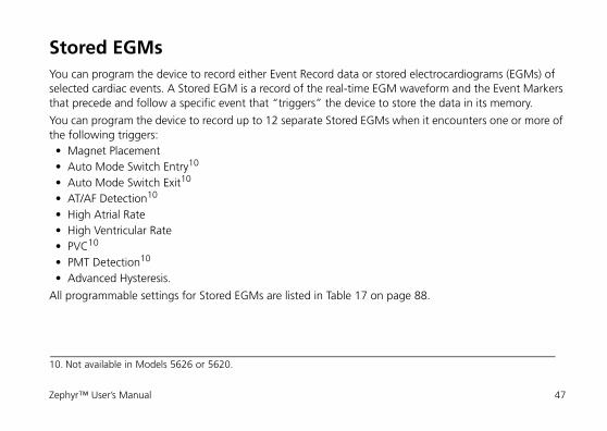
Stored EGMsYou can program the device to record either Event Record data or stored electrocardiograms (EGMs) of selected cardiac events. A Stored EGM is a record of the real-time EGM waveform and the Event Markers that precede and follow a specific event that “triggers” the device to store the data in its memory.
You can program the device to record up to 12 separate Stored EGMs when it encounters one or more of the following triggers:• Magnet Placement• Auto Mode Switch Entry10
• Auto Mode Switch Exit10
• AT/AF Detection10
• High Atrial Rate• High Ventricular Rate• PVC10
• PMT Detection10
• Advanced Hysteresis.
All programmable settings for Stored EGMs are listed in Table 17 on page 88.
10. Not available in Models 5626 or 5620.
Zephyr™ User’s Manual 47
Implantation and Lead ConnectionPackage ContentsZephyr™ pulse generators are shipped in a sterile box containing:• Zephyr pulse generator• Connector kit containing:
- White #2 torque wrench• Literature.
Lead ConnectionZephyr™ device Models 5820 and 5620 accept unipolar or bipolar IS-1 short terminal pin leads. Zephyr device Models 5826 and 5626 accept all unipolar or bipolar IS-1, VS•1, or 3.2 mm leads.
NoteFor the AutoCapture™ Pacing System to function, the pulse generator should be connected to a ventricular bipolar, low polarization pacing lead. For more infor-mation, refer to the Bradycardia Devices Reference Manual or select the HELP but-ton on the Model 3510 Programmer or the Merlin PCS.
48 Implantation and Lead Connection
The pulse generator connector has a single setscrew for each lead pin. The setscrew makes contact with the pin (cathode) securing the lead within the connector while an annular spring makes contact with the proximal ring (anode).
To connect the pulse generator to the leads:1. Remove blood and body fluids from the terminal pins of the implanted leads.2. Use the white-handle #2 torque wrench to retract both setscrews in the device connector so that the
pacing lead terminal pins can be fully inserted.
3. Check the markings on the pulse generator case and verify proper atrial and ventricular connection.4. Insert the lead pin firmly into the connector until it is immobile and visible in the viewport at the
opposite end of the connector.5. Insert the white-handle #2 torque wrench through the aperture on the header and into the setscrew
on the side of the connector.6. Turn the wrench clockwise until it clicks. The wrench is torque-limited and will not allow excessive
tightening.7. Repeat Steps 4 through 6 for the second lead pin in dual-chamber models.
CAUTION
Exercise caution when turning the setscrew, which may be backed out of the con-nector if turned counter-clockwise for more than two rotations.
Zephyr™ User’s Manual 49
8. Tug gently on the lead(s) to ensure they are securely connected to the device.
In order to minimize device migration, secure the pulse generator to the subcutaneous pocket via the suture hole in the device header.
After the device has been implanted and the pocket is closed, interrogate the device and set the Lead Type to the correct setting. Lead Type settings are described in the Bradycardia Devices Reference Manual and the On-Screen Help.
Device RegistrationDevice Registration. An Implantable Device Registration Form is enclosed with each pulse generator to serve as a permanent record of information pertaining to the implanted device. The completed original should be returned to the manufacturer in the postage-paid, addressed envelope provided. Copies of the registration form are provided for the hospital and the physician.
X-Ray IdentificationThe device has a radiopaque identifier, visible on conventional X-ray film, which consists of the St. Jude Medical™ logo and a two-letter model code (Figures 15 through 18).
The code for all Zephyr™ pulse generator models is:
The model number of each pulse generator is stored in the device’s memory and is automatically dis-played on the programmer screen when the device is interrogated.
VW
50 Implantation and Lead Connection
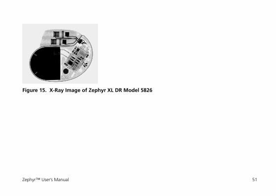
Figure 15. X-Ray Image of Zephyr XL DR Model 5826
Zephyr™ User’s Manual 51

Figure 16. X-Ray Image of Zephyr DR Model 5820
52 Implantation and Lead Connection
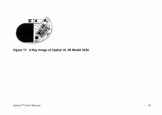
Figure 17. X-Ray Image of Zephyr XL SR Model 5626
Zephyr™ User’s Manual 53
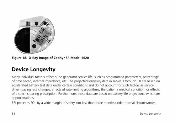
Figure 18. X-Ray Image of Zephyr SR Model 5620
Device LongevityMany individual factors affect pulse generator service life, such as programmed parameters, percentage of time paced, internal impedance, etc. The projected longevity data in Tables 3 through 10 are based on accelerated battery test data under certain conditions and do not account for such factors as sensor-driven pacing rate changes, effects of rate-limiting algorithms, the patient’s medical condition, or effects of a specific pacing prescription. Furthermore, these data are based on battery life projections, which are approximations.
ERI precedes EOL by a wide margin of safety, not less than three months under normal circumstances.
54 Device Longevity
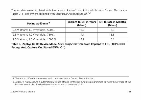
The test data were calculated with Sensor set to Passive11 and Pulse Width set to 0.4 ms. The data in Tables 3, 5, and 9 were obtained with Ventricular AutoCapture On.12
11. There is no difference in current drain between Sensor On and Sensor Passive.12. At ERI, V. AutoCapture is automatically turned off and ventricular output is programmed to twice the average of the
last four ventricular threshold measurements with a minimum of 2 V.
Pacing at 60 min-1 Implant to ERI in Years(Mean)
ERI to EOL in Months(Mean)
2.5 V atrium; 1.0 V ventricle., 500 ¬ 13.0 5.3
2.5 V atrium; 1.0 V ventricle., 750 ¬ 14.1 5.8
2.5 V atrium; 1.0 V ventricle., 1000 ¬ 14.9 6.1
Table 3. Zephyr XL DR Device Model 5826 Projected Time from Implant to EOL (100% DDD Pacing, AutoCapture On, Stored EGMs Off)
Zephyr™ User’s Manual 55
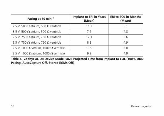
Pacing at 60 min-1 Implant to ERI in Years(Mean)
ERI to EOL in Months(Mean)
2.5 V; 500 ¬ atrium, 500 ¬ ventricle 11.7 5.1
3.5 V; 500 ¬ atrium, 500 ¬ ventricle 7.2 4.8
2.5 V; 750 ¬ atrium, 750 ¬ ventricle 12.1 5.6
3.5 V; 750 ¬ atrium, 750 ¬ ventricle 8.8 4.9
2.5 V; 1000 ¬ atrium, 1000 ¬ ventricle 13.9 6.0
3.5 V; 1000 ¬ atrium, 1000 ¬ ventricle 9.9 4.9
Table 4. Zephyr XL DR Device Model 5826 Projected Time from Implant to EOL (100% DDD Pacing, AutoCapture Off, Stored EGMs Off)
56 Device Longevity
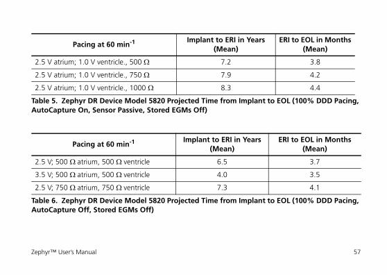
Pacing at 60 min-1 Implant to ERI in Years(Mean)
ERI to EOL in Months(Mean)
2.5 V atrium; 1.0 V ventricle., 500 ¬ 7.2 3.8
2.5 V atrium; 1.0 V ventricle., 750 ¬ 7.9 4.2
2.5 V atrium; 1.0 V ventricle., 1000 ¬ 8.3 4.4
Table 5. Zephyr DR Device Model 5820 Projected Time from Implant to EOL (100% DDD Pacing, AutoCapture On, Sensor Passive, Stored EGMs Off)
Pacing at 60 min-1 Implant to ERI in Years (Mean)
ERI to EOL in Months(Mean)
2.5 V; 500 ¬ atrium, 500 ¬ ventricle 6.5 3.7
3.5 V; 500 ¬ atrium, 500 ¬ ventricle 4.0 3.5
2.5 V; 750 ¬ atrium, 750 ¬ ventricle 7.3 4.1
Table 6. Zephyr DR Device Model 5820 Projected Time from Implant to EOL (100% DDD Pacing, AutoCapture Off, Stored EGMs Off)
Zephyr™ User’s Manual 57
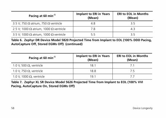
3.5 V; 750 ¬ atrium, 750 ¬ ventricle 4.8 3.5
2.5 V; 1000 ¬ atrium, 1000 ¬ ventricle 7.8 4.3
3.5 V; 1000 ¬ atrium, 1000 ¬ ventricle 5.5 3.5
Pacing at 60 min-1 Implant to ERI in Years(Mean)
ERI to EOL in Months(Mean)
1.0 V, 500 ¬, ventricle 18.1 7.1
1.0 V, 750 ¬, ventricle 18.8 7.5
1.0 V, 1000 ¬, ventricle 19.1 7.7
Table 7. Zephyr XL SR Device Model 5626 Projected Time from Implant to EOL (100% VVI Pacing, AutoCapture On, Stored EGMs Off)
Pacing at 60 min-1 Implant to ERI in Years (Mean)
ERI to EOL in Months(Mean)
Table 6. Zephyr DR Device Model 5820 Projected Time from Implant to EOL (100% DDD Pacing, AutoCapture Off, Stored EGMs Off) (continued)
58 Device Longevity
Pacing at 60 min-1 Implant to ERI in Years(Mean)
ERI to EOL in Months(Mean)
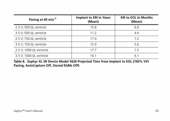
2.5 V; 500 ¬, ventricle 15.8 6.8
3.5 V; 500 ¬, ventricle 11.2 4.9
2.5 V; 750 ¬, ventricle 17.0 7.2
3.5 V; 750 ¬, ventricle 12.9 5.6
2.5 V; 1000 ¬, ventricle 17.7 7.5
3.5 V; 1000 ¬, ventricle 14.1 6.1
Table 8. Zephyr XL SR Device Model 5626 Projected Time from Implant to EOL (100% VVI Pacing, AutoCapture Off, Stored EGMs Off)
Zephyr™ User’s Manual 59
Pacing at 60 min-1 Implant to ERI in Years(Mean)
ERI to EOL in Months(Mean)
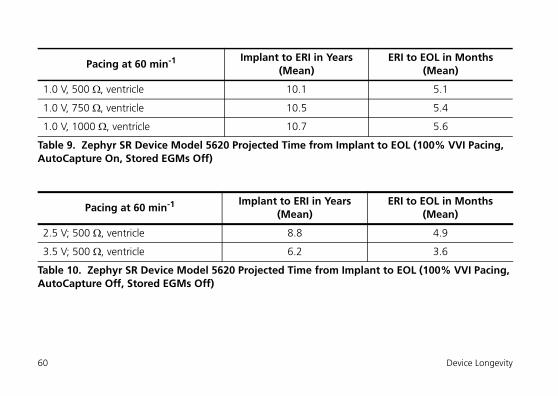
1.0 V, 500 ¬, ventricle 10.1 5.1
1.0 V, 750 ¬, ventricle 10.5 5.4
1.0 V, 1000 ¬, ventricle 10.7 5.6
Table 9. Zephyr SR Device Model 5620 Projected Time from Implant to EOL (100% VVI Pacing, AutoCapture On, Stored EGMs Off)
Pacing at 60 min-1 Implant to ERI in Years(Mean)
ERI to EOL in Months(Mean)
2.5 V; 500 ¬, ventricle 8.8 4.9
3.5 V; 500 ¬, ventricle 6.2 3.6
Table 10. Zephyr SR Device Model 5620 Projected Time from Implant to EOL (100% VVI Pacing, AutoCapture Off, Stored EGMs Off)
60 Device Longevity
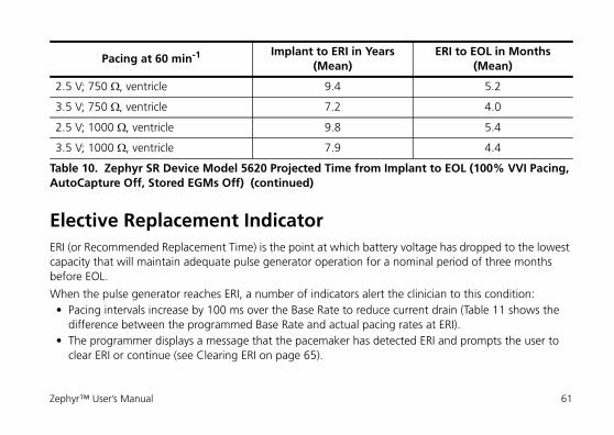
Elective Replacement IndicatorERI (or Recommended Replacement Time) is the point at which battery voltage has dropped to the lowest capacity that will maintain adequate pulse generator operation for a nominal period of three months before EOL.
When the pulse generator reaches ERI, a number of indicators alert the clinician to this condition:• Pacing intervals increase by 100 ms over the Base Rate to reduce current drain (Table 11 shows the
difference between the programmed Base Rate and actual pacing rates at ERI).• The programmer displays a message that the pacemaker has detected ERI and prompts the user to
clear ERI or continue (see Clearing ERI on page 65).
2.5 V; 750 ¬, ventricle 9.4 5.2
3.5 V; 750 ¬, ventricle 7.2 4.0
2.5 V; 1000 ¬, ventricle 9.8 5.4
3.5 V; 1000 ¬, ventricle 7.9 4.4
Pacing at 60 min-1 Implant to ERI in Years(Mean)
ERI to EOL in Months(Mean)
Table 10. Zephyr SR Device Model 5620 Projected Time from Implant to EOL (100% VVI Pacing, AutoCapture Off, Stored EGMs Off) (continued)
Zephyr™ User’s Manual 61
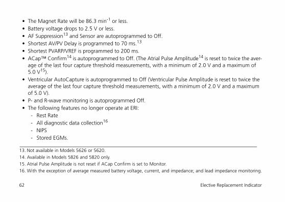
• The Magnet Rate will be 86.3 min-1 or less.• Battery voltage drops to 2.5 V or less.• AF Suppression13 and Sensor are autoprogrammed to Off.• Shortest AV/PV Delay is programmed to 70 ms.13
• Shortest PVARP/VREF is programmed to 200 ms.• ACap™ Confirm14 is autoprogrammed to Off. (The Atrial Pulse Amplitude14 is reset to twice the aver-
age of the last four capture threshold measurements, with a minimum of 2.0 V and a maximum of 5.0 V15).
• Ventricular AutoCapture is autoprogrammed to Off (Ventricular Pulse Amplitude is reset to twice the average of the last four capture threshold measurements, with a minimum of 2.0 V and a maximum of 5.0 V).
• P- and R-wave monitoring is autoprogrammed Off.• The following features no longer operate at ERI:
- Rest Rate- All diagnostic data collection16
- NIPS- Stored EGMs.
13. Not available in Models 5626 or 5620.14. Available in Models 5826 and 5820 only.15. Atrial Pulse Amplitude is not reset if ACap Confirm is set to Monitor.16. With the exception of average measured battery voltage, current, and impedance; and lead impedance monitoring.
62 Elective Replacement Indicator
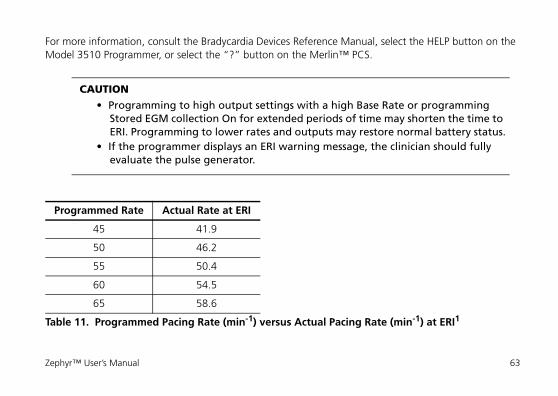
For more information, consult the Bradycardia Devices Reference Manual, select the HELP button on the Model 3510 Programmer, or select the “?” button on the Merlin™ PCS.
CAUTION• Programming to high output settings with a high Base Rate or programming
Stored EGM collection On for extended periods of time may shorten the time to ERI. Programming to lower rates and outputs may restore normal battery status.
• If the programmer displays an ERI warning message, the clinician should fully evaluate the pulse generator.
Programmed Rate Actual Rate at ERI
45 41.9
50 46.2
55 50.4
60 54.5
65 58.6
Table 11. Programmed Pacing Rate (min-1) versus Actual Pacing Rate (min-1) at ERI1
Zephyr™ User’s Manual 63
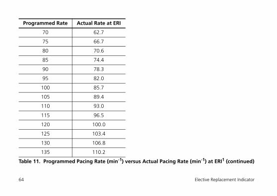
70 62.7
75 66.7
80 70.6
85 74.4
90 78.3
95 82.0
100 85.7
105 89.4
110 93.0
115 96.5
120 100.0
125 103.4
130 106.8
135 110.2
Programmed Rate Actual Rate at ERI
Table 11. Programmed Pacing Rate (min-1) versus Actual Pacing Rate (min-1) at ERI1 (continued)
64 Elective Replacement Indicator
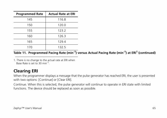
Clearing ERIWhen the programmer displays a message that the pulse generator has reached ERI, the user is presented with two options: [Continue] or [Clear ERI].
Continue. When this is selected, the pulse generator will continue to operate in ERI state with limited functions. The device should be replaced as soon as possible.
145 116.8
150 120.0
155 123.2
160 126.3
165 129.4
170 132.5
1. There is no change to the actual rate at ERI when Base Rate is set to 30 min-1.
Programmed Rate Actual Rate at ERI
Table 11. Programmed Pacing Rate (min-1) versus Actual Pacing Rate (min-1) at ERI1 (continued)
Zephyr™ User’s Manual 65
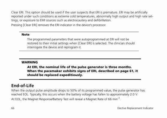
Clear ERI. This option should be used if the user suspects that ERI is premature. ERI may be artificially reported under such conditions as extreme cold temperatures, abnormally high output and high rate set-tings, or exposure to EMI sources such as electrocautery and defibrillation.
Pressing [Clear ERI] removes the ERI indicator in the device’s processor.
End-of-LifeWhen the output pulse amplitude drops to 50% of its programmed value, the pulse generator has reached EOL. Typically, this occurs when the battery voltage has fallen to approximately 2.0 V.
At EOL, the Magnet Response/Battery Test will reveal a Magnet Rate of 66 min-1.
NoteThe programmed parameters that were autoprogrammed at ERI will not be restored to their initial settings when [Clear ERI] is selected. The clinician should interrogate the device and reprogram it.
WARNINGAt ERI, the nominal life of the pulse generator is three months. When the pacemaker exhibits signs of ERI, described on page 61, it should be replaced expeditiously.
66 Elective Replacement Indicator
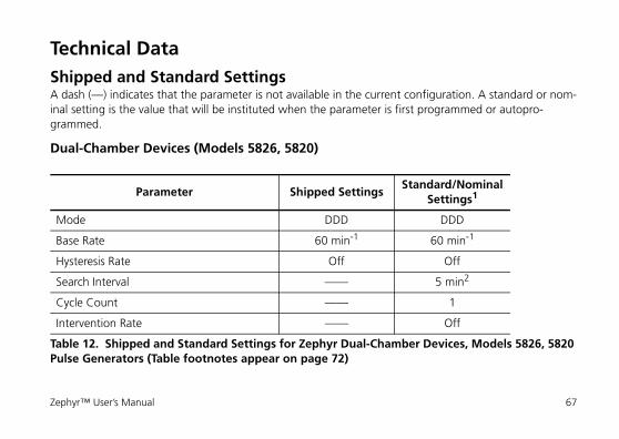
Technical DataShipped and Standard SettingsA dash (—) indicates that the parameter is not available in the current configuration. A standard or nom-inal setting is the value that will be instituted when the parameter is first programmed or autopro-grammed.
Dual-Chamber Devices (Models 5826, 5820)
Parameter Shipped SettingsStandard/Nominal
Settings1
Mode DDD DDD
Base Rate 60 min-1 60 min-1
Hysteresis Rate Off Off
Search Interval —— 5 min2
Cycle Count —— 1
Intervention Rate —— Off
Table 12. Shipped and Standard Settings for Zephyr Dual-Chamber Devices, Models 5826, 5820 Pulse Generators (Table footnotes appear on page 72)
Zephyr™ User’s Manual 67
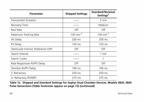
Intervention Duration —— 3 min
Recovery Time —— Medium
Rest Rate Off Off
Maximum Tracking Rate 130 min-1 130 min-1
AV Delay 200 ms 200 ms
PV Delay 150 ms 150 ms
Ventricular Intrinsic Preference (VIP) Off Off
Search Interval —— 1 min
Search Cycles —— 1
Rate Responsive AV/PV Delay Off Off
Shortest AV/PV Delay 100 ms 100 ms
V. Refractory 250 ms 250 ms
A. Refractory (PVARP) 275 ms 275 ms
Parameter Shipped SettingsStandard/Nominal
Settings1
Table 12. Shipped and Standard Settings for Zephyr Dual-Chamber Devices, Models 5826, 5820 Pulse Generators (Table footnotes appear on page 72) (continued)
68 Technical Data
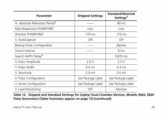
A. Absolute Refractory Period3 —— 60 ms
Rate Responsive PVARP/VREF Low Low
Shortest PVARP/VREF 170 ms 170 ms
V. AutoCapture Off Off
Backup Pulse Configuration —— Bipolar
Search Interval —— 8 hrs
Search AV/PV Delay4 50/25 ms
V. Pulse Amplitude 2.5 V 2.5 V
V. Pulse Width 0.4 ms 0.4 ms
V. Sensitivity 2.0 mV 2.0 mV
V. Pulse Configuration See Package Label See Package Label
V. Sense Configuration See Package Label See Package Label
V. Lead Monitoring Off Monitor
Parameter Shipped SettingsStandard/Nominal
Settings1
Table 12. Shipped and Standard Settings for Zephyr Dual-Chamber Devices, Models 5826, 5820 Pulse Generators (Table footnotes appear on page 72) (continued)
Zephyr™ User’s Manual 69
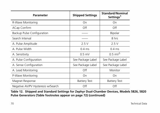
R-Wave Monitoring On On
ACap Confirm Off Off
Backup Pulse Configuration —— Bipolar
Search Interval —— 8 hrs
A. Pulse Amplitude 2.5 V 2.5 V
A. Pulse Width 0.4 ms 0.4 ms
A. Sensitivity 0.5 mV 0.5 mV5
A. Pulse Configuration See Package Label See Package Label
A. Sense Configuration See Package Label See Package Label
A. Lead Monitoring Off Monitor
P-Wave Monitoring On On
Magnet Response Battery Test Battery Test
Negative AV/PV Hysteresis w/Search Off Off
Parameter Shipped SettingsStandard/Nominal
Settings1
Table 12. Shipped and Standard Settings for Zephyr Dual-Chamber Devices, Models 5826, 5820 Pulse Generators (Table footnotes appear on page 72) (continued)
70 Technical Data
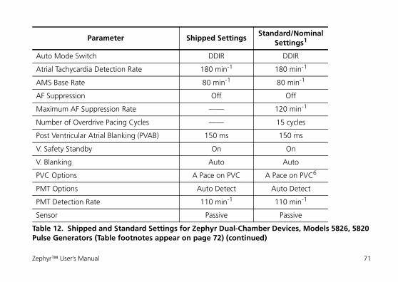
Auto Mode Switch DDIR DDIR
Atrial Tachycardia Detection Rate 180 min-1 180 min-1
AMS Base Rate 80 min-1 80 min-1
AF Suppression Off Off
Maximum AF Suppression Rate —— 120 min-1
Number of Overdrive Pacing Cycles —— 15 cycles
Post Ventricular Atrial Blanking (PVAB) 150 ms 150 ms
V. Safety Standby On On
V. Blanking Auto Auto
PVC Options A Pace on PVC A Pace on PVC6
PMT Options Auto Detect Auto Detect
PMT Detection Rate 110 min-1 110 min-1
Sensor Passive Passive
Parameter Shipped SettingsStandard/Nominal
Settings1
Table 12. Shipped and Standard Settings for Zephyr Dual-Chamber Devices, Models 5826, 5820 Pulse Generators (Table footnotes appear on page 72) (continued)
Zephyr™ User’s Manual 71
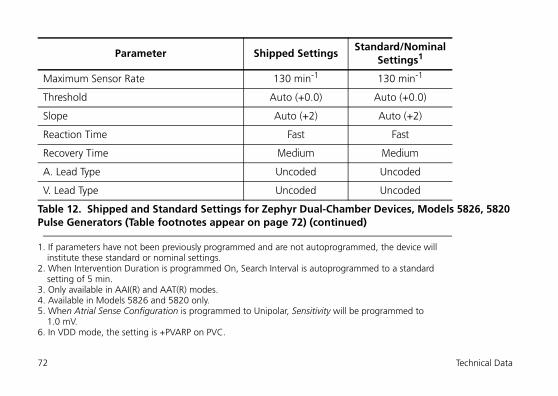
Maximum Sensor Rate 130 min-1 130 min-1
Threshold Auto (+0.0) Auto (+0.0)
Slope Auto (+2) Auto (+2)
Reaction Time Fast Fast
Recovery Time Medium Medium
A. Lead Type Uncoded Uncoded
V. Lead Type Uncoded Uncoded
1. If parameters have not been previously programmed and are not autoprogrammed, the device will institute these standard or nominal settings.
2. When Intervention Duration is programmed On, Search Interval is autoprogrammed to a standard setting of 5 min.
3. Only available in AAI(R) and AAT(R) modes.4. Available in Models 5826 and 5820 only.5. When Atrial Sense Configuration is programmed to Unipolar, Sensitivity will be programmed to
1.0 mV.6. In VDD mode, the setting is +PVARP on PVC.
Parameter Shipped SettingsStandard/Nominal
Settings1
Table 12. Shipped and Standard Settings for Zephyr Dual-Chamber Devices, Models 5826, 5820 Pulse Generators (Table footnotes appear on page 72) (continued)
72 Technical Data
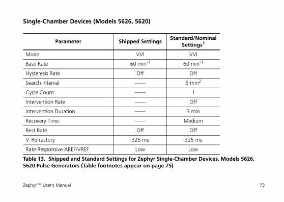
Single-Chamber Devices (Models 5626, 5620)
Parameter Shipped SettingsStandard/Nominal
Settings1
Mode VVI VVI
Base Rate 60 min-1 60 min-1
Hysteresis Rate Off Off
Search Interval —— 5 min2
Cycle Count —— 1
Intervention Rate —— Off
Intervention Duration —— 3 min
Recovery Time —— Medium
Rest Rate Off Off
V. Refractory 325 ms 325 ms
Rate Responsive AREF/VREF Low Low
Table 13. Shipped and Standard Settings for Zephyr Single-Chamber Devices, Models 5626, 5620 Pulse Generators (Table footnotes appear on page 75)
Zephyr™ User’s Manual 73
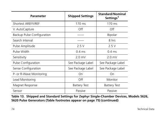
Shortest AREF/VREF 170 ms 170 ms
V. AutoCapture Off Off
Backup Pulse Configuration —— Bipolar
Search Interval —— 8 hrs
Pulse Amplitude 2.5 V 2.5 V
Pulse Width 0.4 ms 0.4 ms
Sensitivity 2.0 mV 2.0 mV
Pulse Configuration See Package Label See Package Label
Sense Configuration See Package Label See Package Label
P- or R-Wave Monitoring On On
Lead Monitoring Off Monitor
Magnet Response Battery Test Battery Test
Sensor Passive Passive
Parameter Shipped SettingsStandard/Nominal
Settings1
Table 13. Shipped and Standard Settings for Zephyr Single-Chamber Devices, Models 5626, 5620 Pulse Generators (Table footnotes appear on page 75) (continued)
74 Technical Data
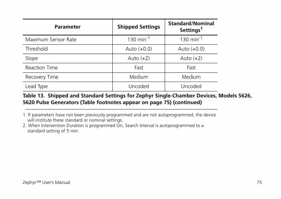
Maximum Sensor Rate 130 min-1 130 min-1
Threshold Auto (+0.0) Auto (+0.0)
Slope Auto (+2) Auto (+2)
Reaction Time Fast Fast
Recovery Time Medium Medium
Lead Type Uncoded Uncoded
1. If parameters have not been previously programmed and are not autoprogrammed, the device will institute these standard or nominal settings.
2. When Intervention Duration is programmed On, Search Interval is autoprogrammed to a standard setting of 5 min.
Parameter Shipped SettingsStandard/Nominal
Settings1
Table 13. Shipped and Standard Settings for Zephyr Single-Chamber Devices, Models 5626, 5620 Pulse Generators (Table footnotes appear on page 75) (continued)
Zephyr™ User’s Manual 75
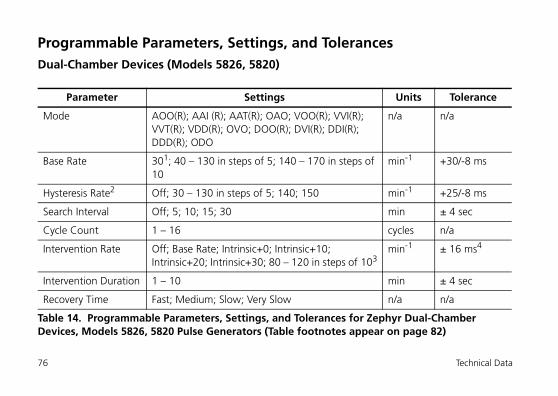
Programmable Parameters, Settings, and TolerancesDual-Chamber Devices (Models 5826, 5820)
Parameter Settings Units Tolerance
Mode AOO(R); AAI (R); AAT(R); OAO; VOO(R); VVI(R); VVT(R); VDD(R); OVO; DOO(R); DVI(R); DDI(R); DDD(R); ODO
n/a n/a
Base Rate 301; 40 – 130 in steps of 5; 140 – 170 in steps of 10
min-1 +30/-8 ms
Hysteresis Rate2 Off; 30 – 130 in steps of 5; 140; 150 min-1 +25/-8 ms
Search Interval Off; 5; 10; 15; 30 min ± 4 sec
Cycle Count 1 – 16 cycles n/a
Intervention Rate Off; Base Rate; Intrinsic+0; Intrinsic+10; Intrinsic+20; Intrinsic+30; 80 – 120 in steps of 103
min-1 ± 16 ms4
Intervention Duration 1 – 10 min ± 4 sec
Recovery Time Fast; Medium; Slow; Very Slow n/a n/a
Table 14. Programmable Parameters, Settings, and Tolerances for Zephyr Dual-Chamber Devices, Models 5826, 5820 Pulse Generators (Table footnotes appear on page 82)
76 Technical Data
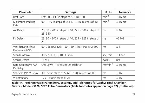
Rest Rate Off; 30 – 130 in steps of 5; 140; 150 min-1 ± 16 ms
Maximum Tracking Rate
90 – 130 in steps of 5; 140 – 180 in steps of 10 min-1 ± 16 ms
AV Delay 25; 30 – 200 in steps of 10; 225 – 300 in steps of 25; 350
ms ± 16
PV Delay 25; 30 – 200 in steps of 10; 225 – 325 in steps of 25
ms +25/-8
Ventricular Intrinsic Preference (VIP)
50; 75; 100; 125; 150; 160; 170; 180; 190; 200 ms ± 8
Search Interval 30 sec; 1, 3, 5, 10, 30 min sec; min ± 4 sec
Search Cycles 1; 2; 3 cycles n/a
Rate Responsive AV/PV Delay
Off; Low (1); Medium (2); High (3) ms/min-1 ± 16 ms
Shortest AV/PV Delay 30 – 50 in steps of 5; 60 – 120 in steps of 10 ms ± 16
V. Refractory 125 – 500 in steps of 25 ms ± 16
Parameter Settings Units Tolerance
Table 14. Programmable Parameters, Settings, and Tolerances for Zephyr Dual-Chamber Devices, Models 5826, 5820 Pulse Generators (Table footnotes appear on page 82) (continued)
Zephyr™ User’s Manual 77
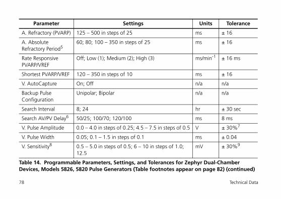
A. Refractory (PVARP) 125 – 500 in steps of 25 ms ± 16
A. Absolute Refractory Period5
60; 80; 100 – 350 in steps of 25 ms ± 16
Rate Responsive PVARP/VREF
Off; Low (1); Medium (2); High (3) ms/min-1 ± 16 ms
Shortest PVARP/VREF 120 – 350 in steps of 10 ms ± 16
V. AutoCapture On; Off n/a n/a
Backup Pulse Configuration
Unipolar; Bipolar n/a n/a
Search Interval 8; 24 hr ± 30 sec
Search AV/PV Delay6 50/25; 100/70; 120/100 ms 8 ms
V. Pulse Amplitude 0.0 – 4.0 in steps of 0.25; 4.5 – 7.5 in steps of 0.5 V ± 30%7
V. Pulse Width 0.05; 0.1 – 1.5 in steps of 0.1 ms ± 0.04
V. Sensitivity8 0.5 – 5.0 in steps of 0.5; 6 – 10 in steps of 1.0; 12.5
mV ± 30%9
Parameter Settings Units Tolerance
Table 14. Programmable Parameters, Settings, and Tolerances for Zephyr Dual-Chamber Devices, Models 5826, 5820 Pulse Generators (Table footnotes appear on page 82) (continued)
78 Technical Data
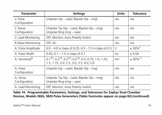
V. Pulse Configuration
Unipolar (tip – case); Bipolar (tip – ring) n/a n/a
V. Sense Configuration
Unipolar Tip (tip – case); Bipolar (tip – ring); Unipolar Ring (ring – case)
n/a n/a
V. Lead Monitoring Off; Monitor; Auto Polarity Switch n/a n/a
R-Wave Monitoring Off; On n/a n/a
A. Pulse Amplitude 0.0 – 4.0 in steps of 0.25; 4.5 – 7.5 in steps of 0.5 V ± 30%7
A. Pulse Width 0.05; 0.1 – 1.5 in steps of 0.1 ms ± 0.04
A. Sensitivity8 0.110; 0.210; 0.310; 0.410; 0.5; 0.75; 1.0; 1.25; 1.5; 1.75; 2.0; 2.5; 3.0; 3.5; 4.0; 5.0
mV ± 30%11
A. Pulse Configuration
Unipolar (tip – case); Bipolar (tip – ring) n/a n/a
A. Sense Configuration
Unipolar Tip (tip – case); Bipolar (tip – ring); Unipolar Ring (ring – case)
n/a n/a
A. Lead Monitoring Off; Monitor; Auto Polarity Switch n/a n/a
Parameter Settings Units Tolerance
Table 14. Programmable Parameters, Settings, and Tolerances for Zephyr Dual-Chamber Devices, Models 5826, 5820 Pulse Generators (Table footnotes appear on page 82) (continued)
Zephyr™ User’s Manual 79
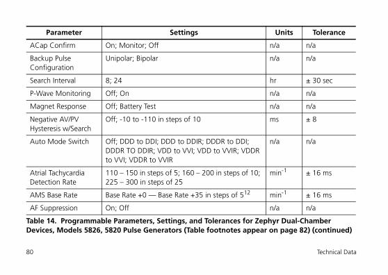
ACap Confirm On; Monitor; Off n/a n/a
Backup Pulse Configuration
Unipolar; Bipolar n/a n/a
Search Interval 8; 24 hr ± 30 sec
P-Wave Monitoring Off; On n/a n/a
Magnet Response Off; Battery Test n/a n/a
Negative AV/PV Hysteresis w/Search
Off; -10 to -110 in steps of 10 ms ± 8
Auto Mode Switch Off; DDD to DDI; DDD to DDIR; DDDR to DDI; DDDR TO DDIR; VDD to VVI; VDD to VVIR; VDDR to VVI; VDDR to VVIR
n/a n/a
Atrial Tachycardia Detection Rate
110 – 150 in steps of 5; 160 – 200 in steps of 10; 225 – 300 in steps of 25
min-1 ± 16 ms
AMS Base Rate Base Rate +0 — Base Rate +35 in steps of 512 min-1 ± 16 ms
AF Suppression On; Off n/a n/a
Parameter Settings Units Tolerance
Table 14. Programmable Parameters, Settings, and Tolerances for Zephyr Dual-Chamber Devices, Models 5826, 5820 Pulse Generators (Table footnotes appear on page 82) (continued)
80 Technical Data
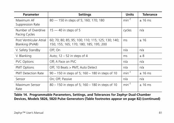
Maximum AF Suppression Rate
80 — 150 in steps of 5; 160; 170; 180 min-1 ± 16 ms
Number of Overdrive Pacing Cycles
15 — 40 in steps of 5 cycles n/a
Post Ventricular AtrialBlanking (PVAB)
60; 70; 80; 85; 95; 100; 110; 115; 125; 130; 140; 150; 155; 165; 170; 180; 185; 195; 200
ms ± 16
V. Safety Standby Off; On n/a n/a
V. Blanking Auto; 12 – 52 in steps of 4 ms ± 8
PVC Options Off; A Pace on PVC n/a n/a
PMT Options Off; 10 Beats > PMT; Auto Detect n/a n/a
PMT Detection Rate 90 – 150 in steps of 5; 160 – 180 in steps of 10 min-1 ± 16 ms
Sensor On; Off; Passive n/a n/a
Maximum Sensor Rate
80 – 150 in steps of 5; 160 – 180 in steps of 10 min-1 ± 16 ms
Parameter Settings Units Tolerance
Table 14. Programmable Parameters, Settings, and Tolerances for Zephyr Dual-Chamber Devices, Models 5826, 5820 Pulse Generators (Table footnotes appear on page 82) (continued)
Zephyr™ User’s Manual 81
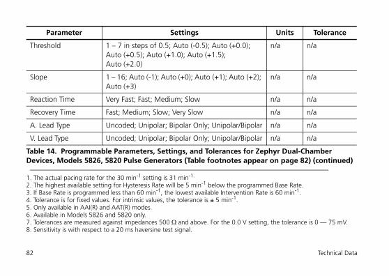
Threshold 1 – 7 in steps of 0.5; Auto (-0.5); Auto (+0.0); Auto (+0.5); Auto (+1.0); Auto (+1.5); Auto (+2.0)
n/a n/a
Slope 1 – 16; Auto (-1); Auto (+0); Auto (+1); Auto (+2); Auto (+3)
n/a n/a
Reaction Time Very Fast; Fast; Medium; Slow n/a n/a
Recovery Time Fast; Medium; Slow; Very Slow n/a n/a
A. Lead Type Uncoded; Unipolar; Bipolar Only; Unipolar/Bipolar n/a n/a
V. Lead Type Uncoded; Unipolar; Bipolar Only; Unipolar/Bipolar n/a n/a
1. The actual pacing rate for the 30 min-1 setting is 31 min-1.
2. The highest available setting for Hysteresis Rate will be 5 min-1 below the programmed Base Rate.3. If Base Rate is programmed less than 60 min-1, the lowest available Intervention Rate is 60 min-1.4. Tolerance is for fixed values. For intrinsic values, the tolerance is ± 5 min-1.5. Only available in AAI(R) and AAT(R) modes.6. Available in Models 5826 and 5820 only.7. Tolerances are measured against impedances 500 ¬ and above. For the 0.0 V setting, the tolerance is 0 — 75 mV.8. Sensitivity is with respect to a 20 ms haversine test signal.
Parameter Settings Units Tolerance
Table 14. Programmable Parameters, Settings, and Tolerances for Zephyr Dual-Chamber Devices, Models 5826, 5820 Pulse Generators (Table footnotes appear on page 82) (continued)
82 Technical Data
Single-Chamber Devices (Models 5626, 5620)
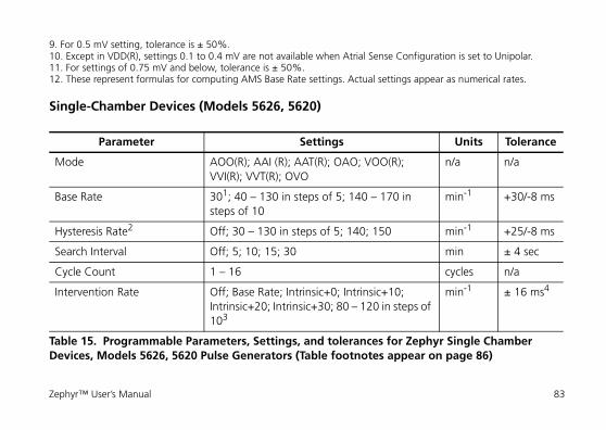
9. For 0.5 mV setting, tolerance is ± 50%.10. Except in VDD(R), settings 0.1 to 0.4 mV are not available when Atrial Sense Configuration is set to Unipolar.11. For settings of 0.75 mV and below, tolerance is ± 50%.12. These represent formulas for computing AMS Base Rate settings. Actual settings appear as numerical rates.
Parameter Settings Units Tolerance
Mode AOO(R); AAI (R); AAT(R); OAO; VOO(R); VVI(R); VVT(R); OVO
n/a n/a
Base Rate 301; 40 – 130 in steps of 5; 140 – 170 in steps of 10
min-1 +30/-8 ms
Hysteresis Rate2 Off; 30 – 130 in steps of 5; 140; 150 min-1 +25/-8 ms
Search Interval Off; 5; 10; 15; 30 min ± 4 sec
Cycle Count 1 – 16 cycles n/a
Intervention Rate Off; Base Rate; Intrinsic+0; Intrinsic+10; Intrinsic+20; Intrinsic+30; 80 – 120 in steps of 103
min-1 ± 16 ms4
Table 15. Programmable Parameters, Settings, and tolerances for Zephyr Single Chamber Devices, Models 5626, 5620 Pulse Generators (Table footnotes appear on page 86)
Zephyr™ User’s Manual 83
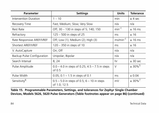
Intervention Duration 1 – 10 min ± 4 sec
Recovery Time Fast; Medium; Slow; Very Slow n/a n/a
Rest Rate Off; 30 – 130 in steps of 5; 140; 150 min-1 ± 16 ms
Refractory 125 – 500 in steps of 25 ms ± 16
Rate Responsive AREF/VREF Off; Low (1); Medium (2); High (3) ms/min-1 ± 16 ms
Shortest AREF/VREF 120 – 350 in steps of 10 ms ± 16
V. AutoCapture On; Off n/a n/a
Backup Pulse Configuration Unipolar; Bipolar n/a n/a
Search Interval 8, 24 hr ± 30 sec
Pulse Amplitude 0.0 – 4.0 in steps of 0.25; 4.5 – 7.5 in steps of 0.5
V ± 30%5
Pulse Width 0.05; 0.1 – 1.5 in steps of 0.1 ms ± 0.04
Sensitivity6 0.5 – 5.0 in steps of 0.5; 6 – 10 in steps of 1.0; 12.5
mV ± 30%7
Parameter Settings Units Tolerance
Table 15. Programmable Parameters, Settings, and tolerances for Zephyr Single Chamber Devices, Models 5626, 5620 Pulse Generators (Table footnotes appear on page 86) (continued)
84 Technical Data
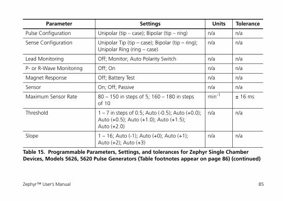
Pulse Configuration Unipolar (tip – case); Bipolar (tip – ring) n/a n/a
Sense Configuration Unipolar Tip (tip – case); Bipolar (tip – ring); Unipolar Ring (ring – case)
n/a n/a
Lead Monitoring Off; Monitor; Auto Polarity Switch n/a n/a
P- or R-Wave Monitoring Off; On n/a n/a
Magnet Response Off; Battery Test n/a n/a
Sensor On; Off; Passive n/a n/a
Maximum Sensor Rate 80 – 150 in steps of 5; 160 – 180 in steps of 10
min-1 ± 16 ms
Threshold 1 – 7 in steps of 0.5; Auto (-0.5); Auto (+0.0); Auto (+0.5); Auto (+1.0); Auto (+1.5); Auto (+2.0)
n/a n/a
Slope 1 – 16; Auto (-1); Auto (+0); Auto (+1); Auto (+2); Auto (+3)
n/a n/a
Parameter Settings Units Tolerance
Table 15. Programmable Parameters, Settings, and tolerances for Zephyr Single Chamber Devices, Models 5626, 5620 Pulse Generators (Table footnotes appear on page 86) (continued)
Zephyr™ User’s Manual 85
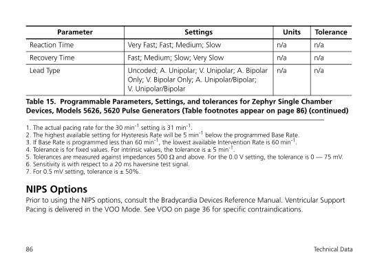
NIPS OptionsPrior to using the NIPS options, consult the Bradycardia Devices Reference Manual. Ventricular Support Pacing is delivered in the VOO Mode. See VOO on page 36 for specific contraindications.
Reaction Time Very Fast; Fast; Medium; Slow n/a n/a
Recovery Time Fast; Medium; Slow; Very Slow n/a n/a
Lead Type Uncoded; A. Unipolar; V. Unipolar; A. Bipolar Only; V. Bipolar Only; A. Unipolar/Bipolar; V. Unipolar/Bipolar
n/a n/a
1. The actual pacing rate for the 30 min-1 setting is 31 min-1.2. The highest available setting for Hysteresis Rate will be 5 min-1 below the programmed Base Rate.3. If Base Rate is programmed less than 60 min-1, the lowest available Intervention Rate is 60 min-1.4. Tolerance is for fixed values. For intrinsic values, the tolerance is ± 5 min-1.5. Tolerances are measured against impedances 500 ¬ and above. For the 0.0 V setting, the tolerance is 0 — 75 mV.6. Sensitivity is with respect to a 20 ms haversine test signal.7. For 0.5 mV setting, tolerance is ± 50%.
Parameter Settings Units Tolerance
Table 15. Programmable Parameters, Settings, and tolerances for Zephyr Single Chamber Devices, Models 5626, 5620 Pulse Generators (Table footnotes appear on page 86) (continued)
86 Technical Data
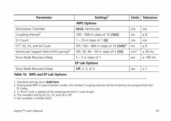
Parameter Settings1
1. Standard settings are in bold face.
Units Tolerance
NIPS Options
Stimulation Chamber Atrial; Ventricular n/a n/a
Coupling Interval2
2. During atrial NIPS in dual-chamber modes, the shortest Coupling Interval will be limited by the programmed AV/PV Delay.
100 – 800 in steps of 10 (500) ms ± 8
S1 Count 1 – 25 in steps of 1 (8) n/a n/a
S13, S2, S3, and S4 Cycle
3. S1 Burst Cycle is applied at the preprogrammed S1 cycle length.
Off; 100 – 800 in steps of 10 (500)4
4. The standard setting for S2, S3, and S4 is Off.
ms ± 6
Ventricular Support Rate (VOO pacing)5
5. Not available in Model 5620.
Off; 30; 40 – 95 in steps of 5 (50) min-1 ± 30 ms
Sinus Node Recovery Delay 1 – 5 in steps of 1 sec ± 100 ms
EP Lab Options
Sinus Node Recovery Delay Off; 2; 3; 4; 5 sec ± 1
Table 16. NIPS and EP Lab Options
Zephyr™ User’s Manual 87
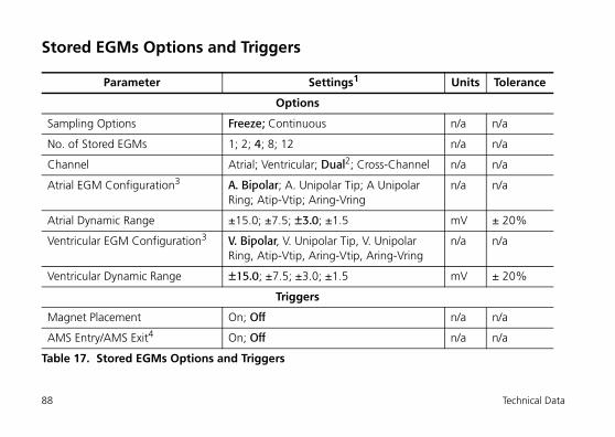
Stored EGMs Options and Triggers
Parameter Settings1 Units Tolerance
Options
Sampling Options Freeze; Continuous n/a n/a
No. of Stored EGMs 1; 2; 4; 8; 12 n/a n/a
Channel Atrial; Ventricular; Dual2; Cross-Channel n/a n/a
Atrial EGM Configuration3 A. Bipolar; A. Unipolar Tip; A Unipolar Ring; Atip-Vtip; Aring-Vring
n/a n/a
Atrial Dynamic Range ±15.0; ±7.5; ±3.0; ±1.5 mV ± 20%
Ventricular EGM Configuration3 V. Bipolar, V. Unipolar Tip, V. Unipolar Ring, Atip-Vtip, Aring-Vtip, Aring-Vring
n/a n/a
Ventricular Dynamic Range ±15.0; ±7.5; ±3.0; ±1.5 mV ± 20%
Triggers
Magnet Placement On; Off n/a n/a
AMS Entry/AMS Exit4 On; Off n/a n/a
Table 17. Stored EGMs Options and Triggers
88 Technical Data
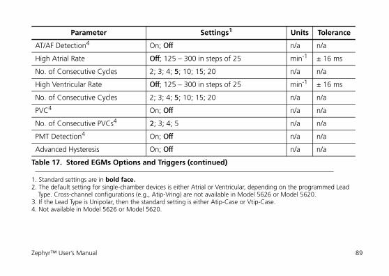
AT/AF Detection4 On; Off n/a n/a
High Atrial Rate Off; 125 – 300 in steps of 25 min-1 ± 16 ms
No. of Consecutive Cycles 2; 3; 4; 5; 10; 15; 20 n/a n/a
High Ventricular Rate Off; 125 – 300 in steps of 25 min-1 ± 16 ms
No. of Consecutive Cycles 2; 3; 4; 5; 10; 15; 20 n/a n/a
PVC4 On; Off n/a n/a
No. of Consecutive PVCs4 2; 3; 4; 5 n/a n/a
PMT Detection4 On; Off n/a n/a
Advanced Hysteresis On; Off n/a n/a
1. Standard settings are in bold face.2. The default setting for single-chamber devices is either Atrial or Ventricular, depending on the programmed Lead
Type. Cross-channel configurations (e.g., Atip-Vring) are not available in Model 5626 or Model 5620.3. If the Lead Type is Unipolar, then the standard setting is either Atip-Case or Vtip-Case.4. Not available in Model 5626 or Model 5620.
Parameter Settings1 Units Tolerance
Table 17. Stored EGMs Options and Triggers (continued)
Zephyr™ User’s Manual 89
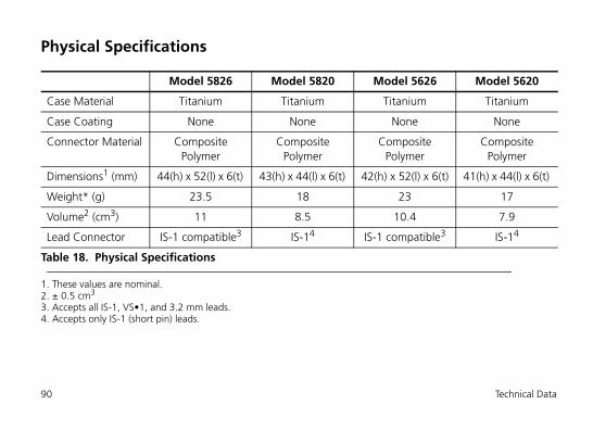
Physical Specifications
Model 5826 Model 5820 Model 5626 Model 5620
Case Material Titanium Titanium Titanium Titanium
Case Coating None None None None
Connector Material Composite Polymer
Composite Polymer
Composite Polymer
Composite Polymer
Dimensions1 (mm)
1. These values are nominal.
44(h) x 52(l) x 6(t) 43(h) x 44(l) x 6(t) 42(h) x 52(l) x 6(t) 41(h) x 44(l) x 6(t)
Weight* (g) 23.5 18 23 17
Volume2 (cm3)
2. ± 0.5 cm3
11 8.5 10.4 7.9
Lead Connector IS-1 compatible3
3. Accepts all IS-1, VS•1, and 3.2 mm leads.
IS-14
4. Accepts only IS-1 (short pin) leads.
IS-1 compatible3 IS-14
Table 18. Physical Specifications
90 Technical Data
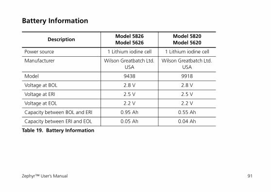
Battery Information
DescriptionModel 5826Model 5626
Model 5820Model 5620
Power source 1 Lithium iodine cell 1 Lithium iodine cell
Manufacturer Wilson Greatbatch Ltd. USA
Wilson Greatbatch Ltd. USA
Model 9438 9918
Voltage at BOL 2.8 V 2.8 V
Voltage at ERI 2.5 V 2.5 V
Voltage at EOL 2.2 V 2.2 V
Capacity between BOL and ERI 0.95 Ah 0.55 Ah
Capacity between ERI and EOL 0.05 Ah 0.04 Ah
Table 19. Battery Information
Zephyr™ User’s Manual 91
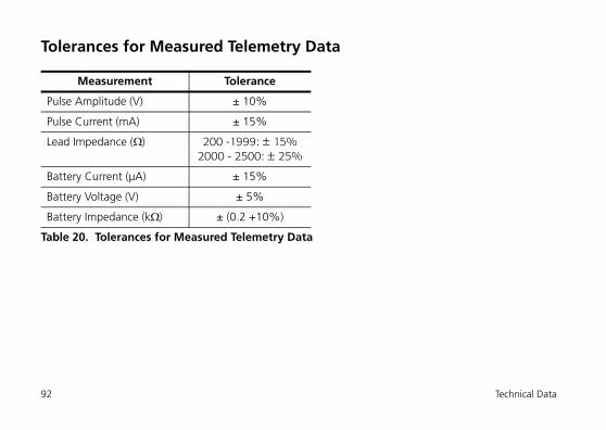
Tolerances for Measured Telemetry Data
Measurement Tolerance
Pulse Amplitude (V) ± 10%
Pulse Current (mA) ± 15%
Lead Impedance (¬) 200 -1999: ± 15%2000 - 2500: ± 25%
Battery Current (μA) ± 15%
Battery Voltage (V) ± 5%
Battery Impedance (k¬) ± (0.2 +10%)
Table 20. Tolerances for Measured Telemetry Data
92 Technical Data
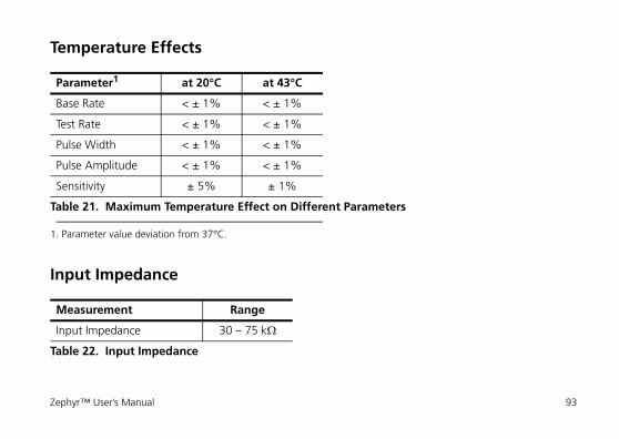
Temperature Effects
Input Impedance
Parameter1
1. Parameter value deviation from 37°C.
at 20°C at 43°C
Base Rate < ± 1% < ± 1%
Test Rate < ± 1% < ± 1%
Pulse Width < ± 1% < ± 1%
Pulse Amplitude < ± 1% < ± 1%
Sensitivity ± 5% ± 1%
Table 21. Maximum Temperature Effect on Different Parameters
Measurement Range
Input Impedance 30 – 75 k¬
Table 22. Input Impedance
Zephyr™ User’s Manual 93
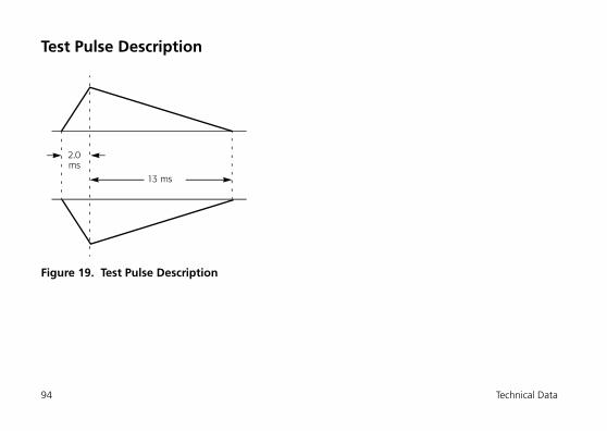
Test Pulse Description
Figure 19. Test Pulse Description
2.0
13 ms
ms
94 Technical Data
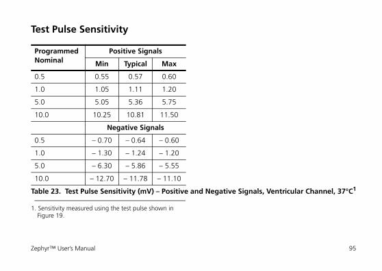
Test Pulse Sensitivity
Programmed Nominal
Positive Signals
Min Typical Max
0.5 0.55 0.57 0.60
1.0 1.05 1.11 1.20
5.0 5.05 5.36 5.75
10.0 10.25 10.81 11.50
Negative Signals
0.5 – 0.70 – 0.64 – 0.60
1.0 – 1.30 – 1.24 – 1.20
5.0 – 6.30 – 5.86 – 5.55
10.0 – 12.70 – 11.78 – 11.10
Table 23. Test Pulse Sensitivity (mV) – Positive and Negative Signals, Ventricular Channel, 37°C1
1. Sensitivity measured using the test pulse shown in Figure 19.
Zephyr™ User’s Manual 95
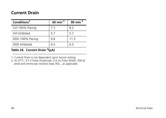
Current Drain
Conditions1
1. Current Drain is not dependent upon Sensor setting.
60 min-1 90 min-1
VVI 100% Pacing 7.3 8.2
VVI Inhibited 5.7 5.7
DDD 100% Pacing 9.8 11.5
DDD Inhibited 6.5 6.5
Table 24. Current Drain 2(μA)
2. At 37°C, 3.5 V Pulse Amplitude, 0.4 ms Pulse Width, 500 ¬ atrial and ventricular resistive load, BOL., as applicable.
96 Technical Data
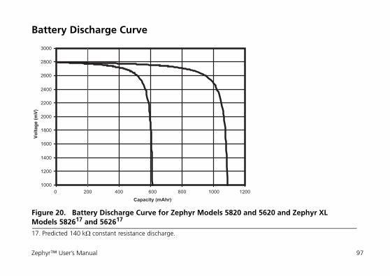
Battery Discharge Curve
Figure 20. Battery Discharge Curve for Zephyr Models 5820 and 5620 and Zephyr XL Models 582617 and 562617
17. Predicted 140 k¬ constant resistance discharge.
1000
1200
1400
1600
1800
2000
2200
2400
2600
2800
3000
0 200 400 600 800 1000 1200Capacity (mAhr)
Volta
ge (m
V)
Zephyr™ User’s Manual 97
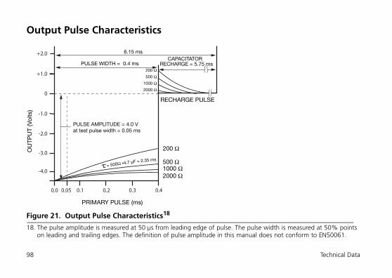
Output Pulse Characteristics
Figure 21. Output Pulse Characteristics18
18. The pulse amplitude is measured at 50 μs from leading edge of pulse. The pulse width is measured at 50% points on leading and trailing edges. The definition of pulse amplitude in this manual does not conform to EN50061.
OU
TPU
T (V
olts
)
PULSE WIDTH = 0.4 ms
PULSE AMPLITUDE = 4.0 Vat test pulse width = 0.05 ms
PRIMARY PULSE (ms)
6.15 ms
RECHARGE PULSE
200 Ω500 Ω
1000 Ω2000 Ω
200 Ω
500 Ω1000 Ω2000 Ω
= 500Ω •4.7 µF = 2.35 ms
CAPACITATOR RECHARGE = 5.75 ms
-1.0
-2.0
0.2 0.3 0.40.10.0 0.05
-3.0
-4.0
0
+1.0
+2.0
98 Technical Data
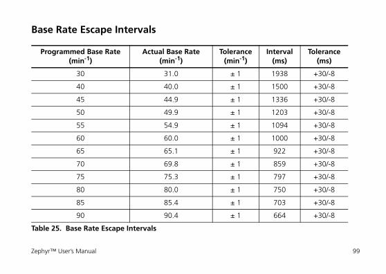
Base Rate Escape Intervals
Programmed Base Rate (min-1)
Actual Base Rate (min-1)
Tolerance (min-1)
Interval (ms)
Tolerance (ms)
30 31.0 ± 1 1938 +30/-8
40 40.0 ± 1 1500 +30/-8
45 44.9 ± 1 1336 +30/-8
50 49.9 ± 1 1203 +30/-8
55 54.9 ± 1 1094 +30/-8
60 60.0 ± 1 1000 +30/-8
65 65.1 ± 1 922 +30/-8
70 69.8 ± 1 859 +30/-8
75 75.3 ± 1 797 +30/-8
80 80.0 ± 1 750 +30/-8
85 85.4 ± 1 703 +30/-8
90 90.4 ± 1 664 +30/-8
Table 25. Base Rate Escape Intervals
Zephyr™ User’s Manual 99
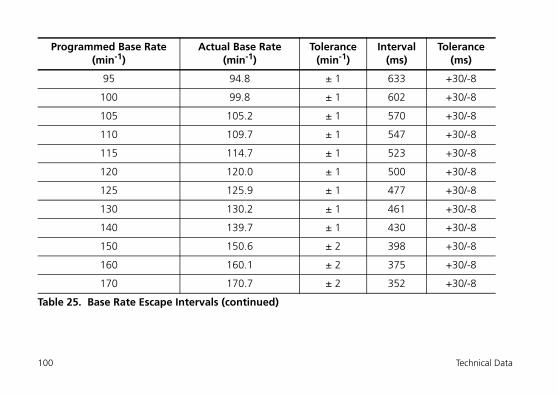
95 94.8 ± 1 633 +30/-8
100 99.8 ± 1 602 +30/-8
105 105.2 ± 1 570 +30/-8
110 109.7 ± 1 547 +30/-8
115 114.7 ± 1 523 +30/-8
120 120.0 ± 1 500 +30/-8
125 125.9 ± 1 477 +30/-8
130 130.2 ± 1 461 +30/-8
140 139.7 ± 1 430 +30/-8
150 150.6 ± 2 398 +30/-8
160 160.1 ± 2 375 +30/-8
170 170.7 ± 2 352 +30/-8
Programmed Base Rate (min-1)
Actual Base Rate (min-1)
Tolerance (min-1)
Interval (ms)
Tolerance (ms)
Table 25. Base Rate Escape Intervals (continued)
100 Technical Data
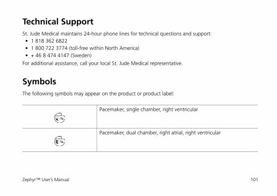
Technical SupportSt. Jude Medical maintains 24-hour phone lines for technical questions and support: • 1 818 362 6822 • 1 800 722 3774 (toll-free within North America) • + 46 8 474 4147 (Sweden)
For additional assistance, call your local St. Jude Medical representative.
SymbolsThe following symbols may appear on the product or product label:
Pacemaker, single chamber, right ventricular
Pacemaker, dual chamber, right atrial, right ventricular
Zephyr™ User’s Manual 101
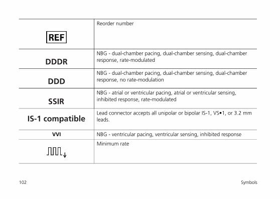
Reorder number
NBG - dual-chamber pacing, dual-chamber sensing, dual-chamber response, rate-modulated
NBG - dual-chamber pacing, dual-chamber sensing, dual-chamber response, no rate-modulation
NBG - atrial or ventricular pacing, atrial or ventricular sensing, inhibited response, rate-modulated
Lead connector accepts all unipolar or bipolar IS-1, VS•1, or 3.2 mm leads.
VVI NBG - ventricular pacing, ventricular sensing, inhibited response
Minimum rate
DDDR
DDD
SSIR
IS-1 compatible
102 Symbols
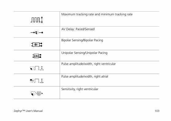
Maximum tracking rate and minimum tracking rate
AV Delay: Paced/Sensed
Bipolar Sensing/Bipolar Pacing
Unipolar Sensing/Unipolar Pacing
Pulse amplitude/width, right ventricular
Pulse amplitude/width, right atrial
Sensitivity, right ventricular
Zephyr™ User’s Manual 103
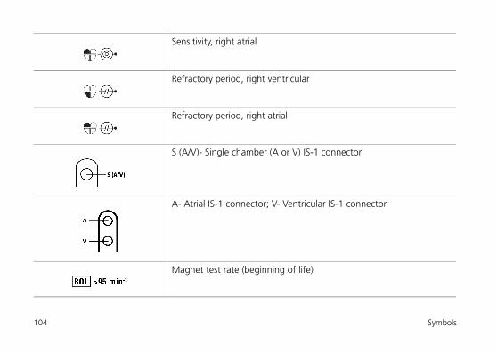
Sensitivity, right atrial
Refractory period, right ventricular
Refractory period, right atrial
S (A/V)- Single chamber (A or V) IS-1 connector
A- Atrial IS-1 connector; V- Ventricular IS-1 connector
Magnet test rate (beginning of life)
104 Symbols
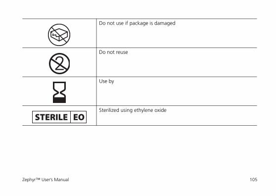
Do not use if package is damaged
Do not reuse
Use by
Sterilized using ethylene oxide
STERILE EO
Zephyr™ User’s Manual 105
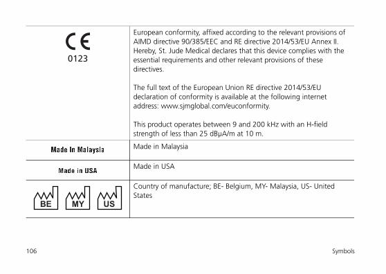
European conformity, affixed according to the relevant provisions of AIMD directive 90/385/EEC and RE directive 2014/53/EU Annex II. Hereby, St. Jude Medical declares that this device complies with the essential requirements and other relevant provisions of these directives.
The full text of the European Union RE directive 2014/53/EU declaration of conformity is available at the following internet address: www.sjmglobal.com/euconformity.
This product operates between 9 and 200 kHz with an H-field strength of less than 25 dBμA/m at 10 m.
Made in Malaysia
Made in USA
Country of manufacture; BE- Belgium, MY- Malaysia, US- United States
0123
MYBE US
106 Symbols
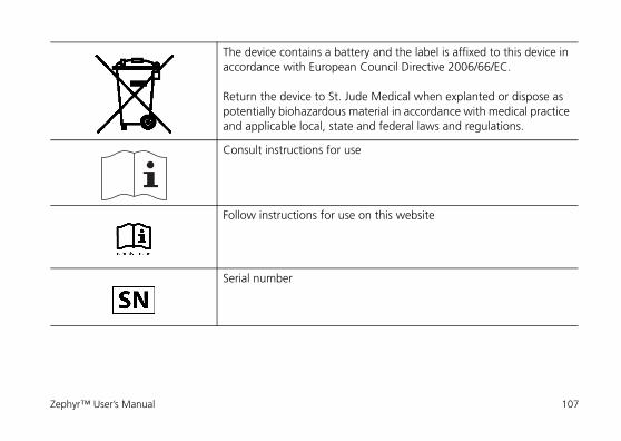
The device contains a battery and the label is affixed to this device in accordance with European Council Directive 2006/66/EC.
Return the device to St. Jude Medical when explanted or dispose as potentially biohazardous material in accordance with medical practice and applicable local, state and federal laws and regulations.
Consult instructions for use
Follow instructions for use on this website
Serial number
Zephyr™ User’s Manual 107
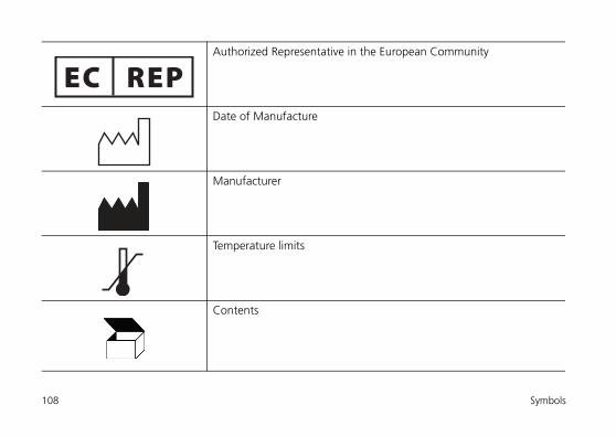
Authorized Representative in the European Community
Date of Manufacture
Manufacturer
Temperature limits
Contents
108 Symbols
Implantable device
Product literature
Accessories
Zephyr™ User’s Manual 109

110 Symbols


April 2017ARTEN100159844 A 2006
0123
European Authorized Representative:St. Jude MedicalCoordination Center BVBAThe Corporate VillageDa Vincilaan 11 Box F11935 ZaventemBelgium+32 2 774 68 11
Manufacturing Site:St. Jude Medical Puerto Rico LLCLot A Interior - #2 Rd Km. 67.5Santana Industrial ParkArecibo, PR 00612USA
Manufacturer:St. Jude MedicalCardiac Rhythm Management Division15900 Valley View CourtSylmar, CA 91342 USA+1 818 362 6822
sjm.com
Manufacturing Site:St. Jude Medical Operations (M) Sdn. Bhd.Plot 102, Lebuhraya Kampung Jawa,Bayan Lepas Industrial Zone11900 PenangMalaysia
Australian Sponsor:St. Jude Medical Australia Pty. Limited17 Orion RoadLane Cove NSW 2066Australia
+32 2 774 68 11