Embed Size (px)
Citation preview

USER'S MANUAL
Thank you very much for purchasing the PNC-2300A.
• To ensure correct and safe usage with a full under-standing of this product's performance, please be sureto read through this manual completely and store it ina safe location.
• Unauthorized copying or transferral, in whole or inpart, of this manual is prohibited.
• The contents of this operation manual and thespecifications of this product are subject to changewithout notice.
• The operation manual and the product have beenprepared and tested as much as possible. If you findany misprint or error, please inform us.
For the USA
FEDERAL COMMUNICATIONS COMMISSIONRADIO FREQUENCY INTERFERENCE
STATEMENT
This equipment has been tested and found to comply with thelimits for a Class A digital device, pursuant to Part 15 of theFCC Rules.These limits are designed to provide reasonable protectionagainst harmful interference when the equipment is operatedin a commercial environment.This equipment generates, uses, and can radiate radiofrequency energy and, if not installed and used in accordancewith the instruction manual, may cause harmful interferenceto radio communications.Operation of this equipment in a residential area is likely tocause harmful interference in which case the user will berequired to correct the interference at his own expense.
Unauthorized changes or modification to this system can voidthe users authority to operate this equipment.
The I/O cables between this equipment and the computingdevice must be shielded.
For Canada
CLASS A NOTICE
This Class A digital apparatus meets all requirements of theCanadian Interference-Causing Equipment Regulations.
CLASSE A AVIS
Cet appareil numérique de la classe A respecte toutes lesexigences du Règlement sur le matériel brouilleur duCanada.
NOTICEGrounding Instructions
Do not modify the plug provided - if it will not fit the outlet,have the proper outlet installed by a qualified electrician.
Check with qualified electrician or service personnel if thegrounding instructions are not completely understood, or if indoubt as to whether the tool is properly grounded.
Use only 3-wire extension cords that have 3-pronggrounding plugs and 3-pole receptacles that accept the tool’splug.
Repair or replace damaged or worn out cord immediately.
Operating Instructions
KEEP WORK AREA CLEAN. Cluttered areas and benchesinvites accidents.
DON’T USE IN DANGEROUS ENVIRONMENT. Don’tuse power tools in damp or wet locations, or expose them torain. Keep work area well lighted.
DISCONNECT TOOLS before servicing; when changingaccessories, such as blades, bits, cutters, and like.
REDUCE THE RISK OF UNINTENTIONAL STARTING.Make sure the switch is in off position before plugging in.
USE RECOMMENDED ACCESSORIES. Consult theowner’s manual for recommended accessories. The use ofimproper accessories may cause risk of injury to persons.
NEVER LEAVE TOOL RUNNING UNATTENDED.TURN POWER OFF. Don’t leave tool until it comes to acomplete stop.
ROLAND DG CORPORATION1-6-4 Shinmiyakoda, Hamamatsu-shi, Shizuoka-ken, JAPAN 431-2103MODEL NAME : See the MODEL given on the rating plate.RELEVANT DIRECTIVE : EC MACHINERY DIRECTIVE (89/392/EEC)
EC LOW VOLTAGE DIRECTIVE (73/23/EEC)EC ELECTROMAGNETIC COMPATIBILITY DIRECTIVE (89/336/EEC)

1
Table of ContentsTo Ensure Safe Use ..............................................................................................................................2
About the Labels Affixed to the Unit ..................................................................................................5
Part 1 Startup
1-1 Checking the Accessories ..................................................................................................................7
1-2 Part Names and Functions ................................................................................................................8
1-3 Installation and Connections ........................................................................................................... 10
1-4 Installing the Software ..................................................................................................................... 12
1-5 Setting the Connection Parameters ............................................................................................... 17
1-6 Loading a Workpiece for Cutting .................................................................................................... 18
1-7 Loading a Cutter ............................................................................................................................... 19
1-8 Vacuum Cleaner Connection .......................................................................................................... 24
1-9 Setting the Origin (Home Position) ................................................................................................ 26
1-10 Cutting Condition Setting ................................................................................................................. 26
1-11 Setting the Z1 and Z2 Position ...................................................................................................... 29
1-12 Sending Cutting Data ....................................................................................................................... 30
1-13 Finishing ............................................................................................................................................. 31
Part 2 User's Reference
2-1 Cutting Area ....................................................................................................................................... 33
2-2 Operating Each Function ................................................................................................................. 34
2-3 Explanation of the Display Menus ................................................................................................. 38
2-4 Maintenance ...................................................................................................................................... 41
2-5 Troubleshooting ................................................................................................................................ 45
2-6 Error Messages ................................................................................................................................. 47
2-7 Other Messages ............................................................................................................................... 48
2-8 List of CAMM-GL I Instructions ...................................................................................................... 49
2-9 Device Control Instructions ............................................................................................................. 52
2-10 Display Menus Flowchart ................................................................................................................ 54
2-11 List of Options ................................................................................................................................... 56
2-12 Specifications .................................................................................................................................... 57
Index ............................................................................................................................................................ 59
Copyright © 1998-2000 ROLAND DG CORPORATION
Windows® and Windows NT® are registered trademark or trademark of Microsoft® Corporation in the United States and/or other coun-tries.Mac OS, Macintosh, Power Macintosh, Power Book, and Apple logo are registered trademarks or trademarks of Apple Computer, Inc. inthe USA and other countries.i486 and Pentium are registered trademarks of Intel Corporation in the United States.IBM is a registered trademark of International Business Corporation.
2
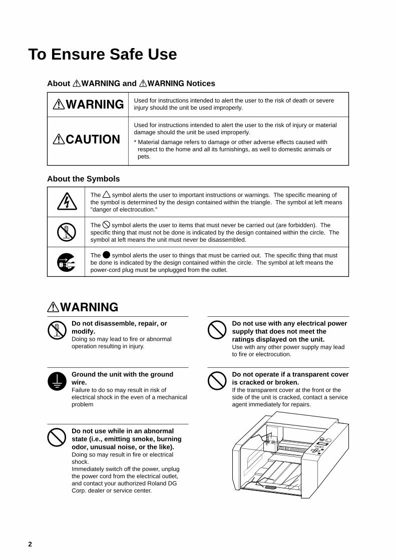
To Ensure Safe Use
Used for instructions intended to alert the user to the risk of death or severeinjury should the unit be used improperly.
About and Notices
Used for instructions intended to alert the user to the risk of injury or materialdamage should the unit be used improperly.
* Material damage refers to damage or other adverse effects caused withrespect to the home and all its furnishings, as well to domestic animals orpets.
About the Symbols
The symbol alerts the user to important instructions or warnings. The specific meaning ofthe symbol is determined by the design contained within the triangle. The symbol at left means"danger of electrocution."
The symbol alerts the user to items that must never be carried out (are forbidden). Thespecific thing that must not be done is indicated by the design contained within the circle. Thesymbol at left means the unit must never be disassembled.
The symbol alerts the user to things that must be carried out. The specific thing that mustbe done is indicated by the design contained within the circle. The symbol at left means thepower-cord plug must be unplugged from the outlet.
Do not disassemble, repair, ormodify.Doing so may lead to fire or abnormaloperation resulting in injury.
Ground the unit with the groundwire.Failure to do so may result in risk ofelectrical shock in the even of a mechanicalproblem
Do not use with any electrical powersupply that does not meet theratings displayed on the unit.Use with any other power supply may leadto fire or electrocution.
Do not use while in an abnormalstate (i.e., emitting smoke, burningodor, unusual noise, or the like).Doing so may result in fire or electricalshock.Immediately switch off the power, unplugthe power cord from the electrical outlet,and contact your authorized Roland DGCorp. dealer or service center.
Do not operate if a transparent coveris cracked or broken.If the transparent cover at the front or theside of the unit is cracked, contact a serviceagent immediately for repairs.
3
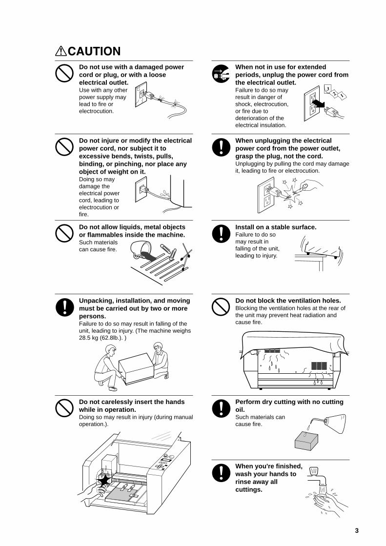
Do not use with a damaged powercord or plug, or with a looseelectrical outlet.Use with any otherpower supply maylead to fire orelectrocution.
Do not injure or modify the electricalpower cord, nor subject it toexcessive bends, twists, pulls,binding, or pinching, nor place anyobject of weight on it.Doing so maydamage theelectrical powercord, leading toelectrocution orfire.
When not in use for extendedperiods, unplug the power cord fromthe electrical outlet.Failure to do so mayresult in danger ofshock, electrocution,or fire due todeterioration of theelectrical insulation.
When unplugging the electricalpower cord from the power outlet,grasp the plug, not the cord.Unplugging by pulling the cord may damageit, leading to fire or electrocution.
Install on a stable surface.Failure to do somay result infalling of the unit,leading to injury.
Do not allow liquids, metal objectsor flammables inside the machine.Such materialscan cause fire.
Unpacking, installation, and movingmust be carried out by two or morepersons.Failure to do so may result in falling of theunit, leading to injury. (The machine weighs28.5 kg (62.8lb.). )
Do not block the ventilation holes.Blocking the ventilation holes at the rear ofthe unit may prevent heat radiation andcause fire.
Do not carelessly insert the handswhile in operation.Doing so may result in injury (during manualoperation.).
Perform dry cutting with no cuttingoil.Such materials cancause fire.
When you're finished,wash your hands torinse away allcuttings.

4
Do not touch the tip of the bladewith your fingers.Doing so may result in injury.
Please use a vacuum cleaner toremove cutting dust.Do not use any blower like airbrush.Otherwise, dust spread in the air may harmyour health.
Before attempting to replace themotor brushes or the spindle motor,stop cutting operations on the PNC-2300A and allow to stand for an houror so.Failure to do so may result in burns fromthe hot motor.
Do not attempt to unplug the powercord with wet hands. Doing so mayresult in electricalshock.
5
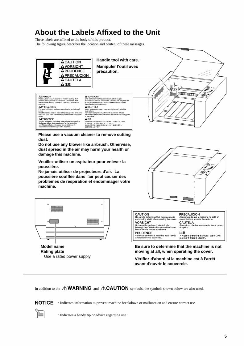
About the Labels Affixed to the UnitThese labels are affixed to the body of this product.The following figure describes the location and content of these messages.
: Indicates information to prevent machine breakdown or malfunction and ensure correct use.
: Indicates a handy tip or advice regarding use.
In addition to the and symbols, the symbols shown below are also used.
NOTICE
Handle tool with care.
Manipuler l'outil avecprécaution.
Please use a vacuum cleaner to remove cuttingdust.Do not use any blower like airbrush. Otherwise,dust spread in the air may harm your health ordamage this machine.
Veuillez utiliser un aspirateur pour enlever lapoussière.Ne jamais utiliser de projecteurs d'air. Lapoussière soufflée dans l'air peut causer desproblèmes de respiration et endommager votremachine.
Be sure to determine that the machine is notmoving at all, when operating the cover.
Vérifiez d'abord si la machine est à l'arrétavant d'ouvrir le couvercle.
Model nameRating plate
Use a rated power supply.

6
MEMO
Part 1
7
Part 1 Startup
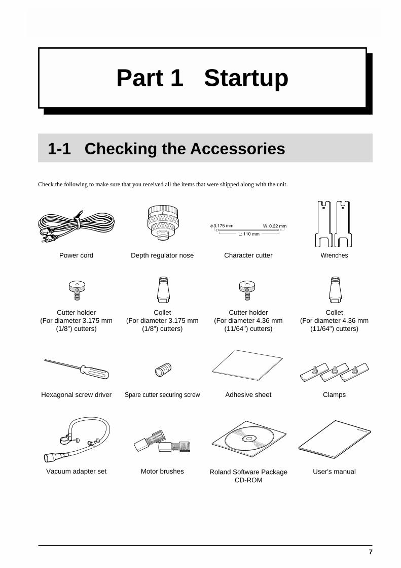
1-1 Checking the Accessories
Check the following to make sure that you received all the items that were shipped along with the unit.
WrenchesPower cord Depth regulator nose Character cutter
Collet(For diameter 4.36 mm
(11/64") cutters)
Cutter holder(For diameter 4.36 mm
(11/64") cutters)
Collet(For diameter 3.175 mm
(1/8") cutters)
Hexagonal screw driver Spare cutter securing screw Adhesive sheet Clamps
Cutter holder(For diameter 3.175 mm
(1/8") cutters)
Vacuum adapter set Motor brushes User's manualRoland Software PackageCD-ROM
Part 1
8
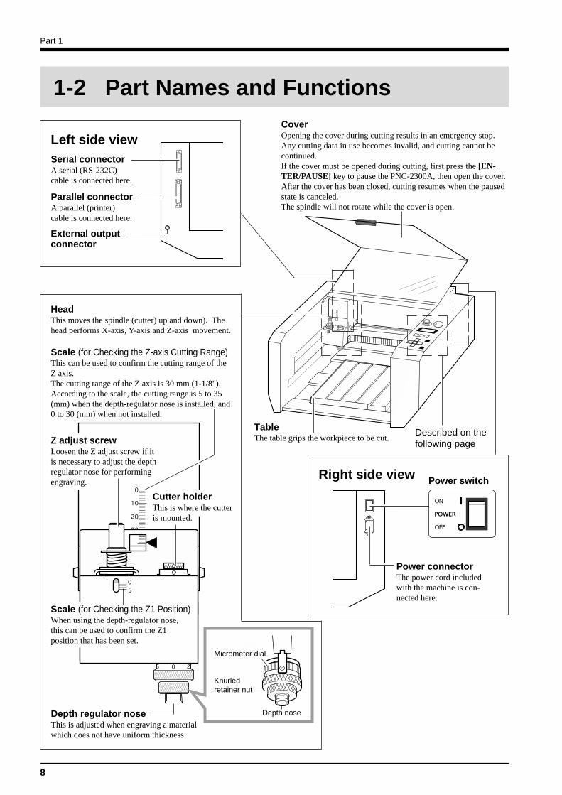
Depth regulator noseThis is adjusted when engraving a materialwhich does not have uniform thickness.
CoverOpening the cover during cutting results in an emergency stop.Any cutting data in use becomes invalid, and cutting cannot becontinued.If the cover must be opened during cutting, first press the [EN-TER/PAUSE] key to pause the PNC-2300A, then open the cover.After the cover has been closed, cutting resumes when the pausedstate is canceled.The spindle will not rotate while the cover is open.
Parallel connectorA parallel (printer)cable is connected here.
Serial connectorA serial (RS-232C)cable is connected here.
Left side view
HeadThis moves the spindle (cutter) up and down). Thehead performs X-axis, Y-axis and Z-axis movement.
Scale (for Checking the Z-axis Cutting Range)This can be used to confirm the cutting range of theZ axis.The cutting range of the Z axis is 30 mm (1-1/8").According to the scale, the cutting range is 5 to 35(mm) when the depth-regulator nose is installed, and0 to 30 (mm) when not installed.
Cutter holderThis is where the cutteris mounted.
1-2 Part Names and Functions
TableThe table grips the workpiece to be cut.
Described on thefollowing page
External outputconnector
Right side view Power switch
Power connectorThe power cord includedwith the machine is con-nected here.
Scale (for Checking the Z1 Position)When using the depth-regulator nose,this can be used to confirm the Z1position that has been set.
Z adjust screwLoosen the Z adjust screw if itis necessary to adjust the depthregulator nose for performingengraving.
Depth nose
Knurledretainer nut
Micrometer dial
Part 1
9
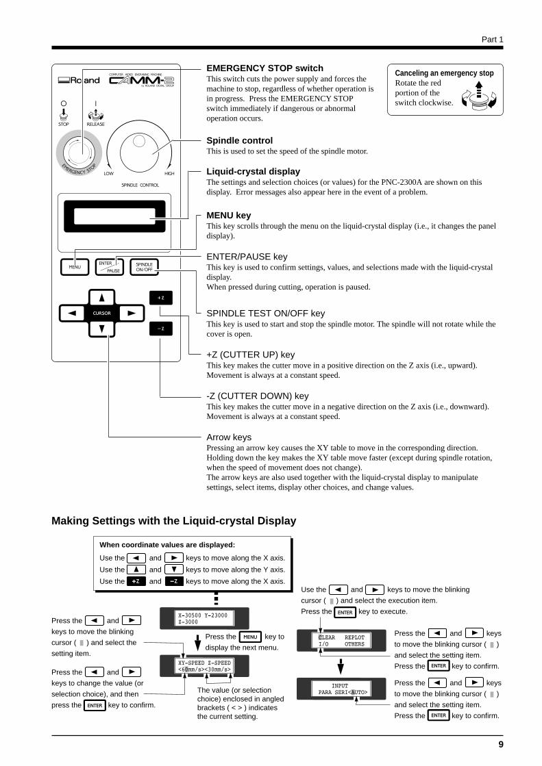
Making Settings with the Liquid-crystal Display
EMERGENCY STOP switchThis switch cuts the power supply and forces themachine to stop, regardless of whether operation isin progress. Press the EMERGENCY STOPswitch immediately if dangerous or abnormaloperation occurs.
Canceling an emergency stopRotate the redportion of theswitch clockwise.
Spindle controlThis is used to set the speed of the spindle motor.
Liquid-crystal displayThe settings and selection choices (or values) for the PNC-2300A are shown on thisdisplay. Error messages also appear here in the event of a problem.
MENU keyThis key scrolls through the menu on the liquid-crystal display (i.e., it changes the paneldisplay).
ENTER/PAUSE keyThis key is used to confirm settings, values, and selections made with the liquid-crystaldisplay.When pressed during cutting, operation is paused.
SPINDLE TEST ON/OFF keyThis key is used to start and stop the spindle motor. The spindle will not rotate while thecover is open.
+Z (CUTTER UP) keyThis key makes the cutter move in a positive direction on the Z axis (i.e., upward).Movement is always at a constant speed.
-Z (CUTTER DOWN) keyThis key makes the cutter move in a negative direction on the Z axis (i.e., downward).Movement is always at a constant speed.
Arrow keysPressing an arrow key causes the XY table to move in the corresponding direction.Holding down the key makes the XY table move faster (except during spindle rotation,when the speed of movement does not change).The arrow keys are also used together with the liquid-crystal display to manipulatesettings, select items, display other choices, and change values.
When coordinate values are displayed:
Use the and keys to move along the X axis.
Use the and keys to move along the Y axis.
Use the and keys to move along the X axis.
Press the and
keys to move the blinking
cursor ( ) and select the
setting item.
Press the and
keys to change the value (or
selection choice), and then
press the key to confirm.
Press the key to
display the next menu.
The value (or selection choice) enclosed in angled brackets ( < > ) indicates the current setting.
Use the and keys to move the blinking
cursor ( ) and select the execution item.
Press the key to execute.
Press the and keys
to move the blinking cursor ( )
and select the setting item.
Press the key to confirm.
Press the and keys
to move the blinking cursor ( )
and select the setting item.
Press the key to confirm.
Part 1
10
Installation
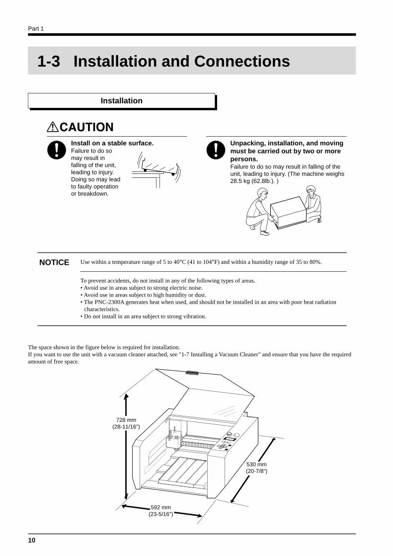
1-3 Installation and Connections
Install on a stable surface.Failure to do somay result infalling of the unit,leading to injury.Doing so may leadto faulty operationor breakdown.
Unpacking, installation, and movingmust be carried out by two or morepersons.Failure to do so may result in falling of theunit, leading to injury. (The machine weighs28.5 kg (62.8lb.). )
Use within a temperature range of 5 to 40°C (41 to 104°F) and within a humidity range of 35 to 80%.
To prevent accidents, do not install in any of the following types of areas.• Avoid use in areas subject to strong electric noise.• Avoid use in areas subject to high humidity or dust.• The PNC-2300A generates heat when used, and should not be installed in an area with poor heat radiation
characteristics.• Do not install in an area subject to strong vibration.
NOTICE
728 mm(28-11/16")
530 mm(20-7/8")
592 mm(23-5/16")
The space shown in the figure below is required for installation.If you want to use the unit with a vacuum cleaner attached, see "1-7 Installing a Vacuum Cleaner" and ensure that you have the requiredamount of free space.
Part 1
11
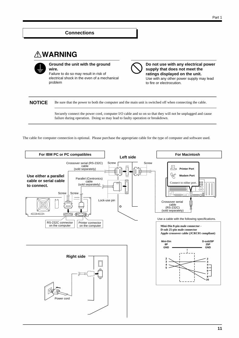
Connections
Ground the unit with the groundwire.Failure to do so may result in risk ofelectrical shock in the even of a mechanicalproblem
Do not use with any electrical powersupply that does not meet theratings displayed on the unit.Use with any other power supply may leadto fire or electrocution.
NOTICE Be sure that the power to both the computer and the main unit is switched off when connecting the cable.
Securely connect the power cord, computer I/O cable and so on so that they will not be unplugged and causefailure during operation. Doing so may lead to faulty operation or breakdown.
The cable for computer connection is optional. Please purchase the appropriate cable for the type of computer and software used.
Crossover serial (RS-232C) cable
(sold separately)
Screw
Lock-use pin
RS-232C connectoron the computer
Use either a parallelcable or serial cableto connect.
Power cord
Left side
Right side
Printer connector on the computer
Parallel (Centronics) cable
(sold separately)
Screw
Mini-Din8P
GND
D-sub25P25PGND
2345
Crossover serial cable
(RS-232C)(sold separately)
Printer Port
Modem Port
Connect to either port.
Use a cable with the following specifications.
Mini-Din 8-pin male connector - D-sub 25-pin male connectorApple crossover cable (JCRC01 compliant)
For IBM PC or PC compatibles For Macintosh
Screw Screw
234567820
Part 1
12
MODELA Applications Dr. Engrave 3D Engrave Virtual MODELA
Personal computer running Windows 95, Windows 98, or Windows NT 4.0
If you're using Windows 95: i486SX or better (Pentium 100 MHz recommended)If you're using Windows 98 or Windows NT 4.0: i486DX or better (Pentium 100 MHz recommended)
If you're using Windows 95: 8 MB or more (10 MB or more recommended)If you're using Windows 98 or Windows NT 4.0: 16 MB or more (32 MB or more recommended)
7 MB or more 10 MB or more 10 MB or more 5 MB or moreof free space of free space of free space of free space
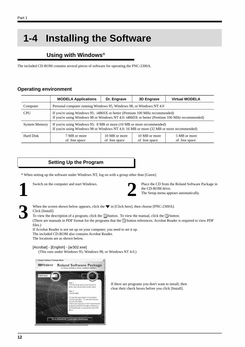
1-4 Installing the Software
Using with Windows®
The included CD-ROM contains several pieces of software for operating the PNC-2300A.
Setting Up the Program
Switch on the computer and start Windows.1 Place the CD from the Roland Software Package inthe CD-ROM drive.The Setup menu appears automatically.2
When the screen shown below appears, click the in [Click here], then choose [PNC-2300A].Click [Install].To view the description of a program, click the button. To view the manual, click the button.(There are manuals in PDF format for the programs that the button references. Acrobat Reader is required to view PDFfiles.)If Acrobat Reader is not set up on your computer, you need to set it up.The included CD-ROM also contains Acrobat Reader.The locations are as shown below.
[Acrobat] - [English] - [ar302.exe](This runs under Windows 95, Windows 98, or Windows NT 4.0.)
3
* When setting up the software under Windows NT, log on with a group other than [Guest].
Operating environment
Computer
CPU
System Memory
Hard Disk
If there are programs you don't want to install, thenclear their check boxes before you click [Install].
Part 1
13
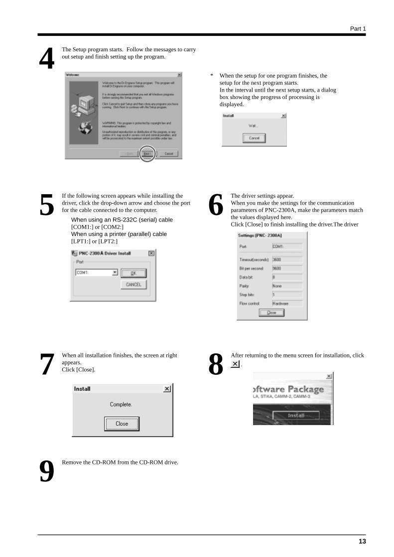
The Setup program starts. Follow the messages to carryout setup and finish setting up the program.4
When all installation finishes, the screen at rightappears.Click [Close].7
* When the setup for one program finishes, thesetup for the next program starts.In the interval until the next setup starts, a dialogbox showing the progress of processing isdisplayed.
The driver settings appear.When you make the settings for the communicationparameters of PNC-2300A, make the parameters matchthe values displayed here.Click [Close] to finish installing the driver.The driver
6If the following screen appears while installing thedriver, click the drop-down arrow and choose the portfor the cable connected to the computer.
When using an RS-232C (serial) cable[COM1:] or [COM2:]When using a printer (parallel) cable[LPT1:] or [LPT2:]
5
After returning to the menu screen for installation, click
.8
Remove the CD-ROM from the CD-ROM drive.9
Part 1
14
How to use Help
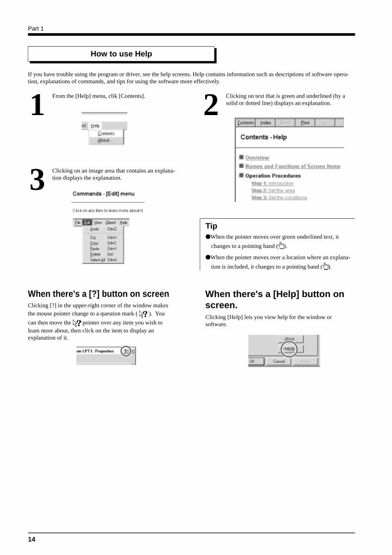
From the [Help] menu, clik [Contents].1 Clicking on text that is green and underlined (by asolid or dotted line) displays an explanation.2
Clicking on an image area that contains an explana-tion displays the explanation.3
When the pointer moves over green underlined text, it
changes to a pointing hand ( ).
When the pointer moves over a location where an explana-
tion is included, it changes to a pointing hand ( ).
Tip
When there's a [?] button on screen When there's a [Help] button onscreen.Clicking [Help] lets you view help for the window orsoftware.
Clicking [?] in the upper-right corner of the window makesthe mouse pointer change to a question mark ( ). You
can then move the pointer over any item you wish toleam more about, then click on the item to display anexplanation of it.
If you have trouble using the program or driver, see the help screens. Help contains information such as descriptions of software opera-tion, explanations of commands, and tips for using the software more effectively.
Part 1
15
Using with Macintosh
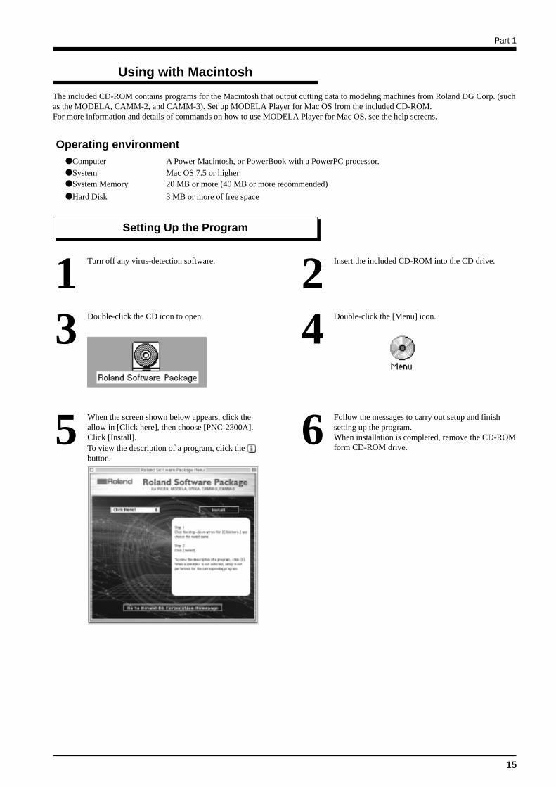
The included CD-ROM contains programs for the Macintosh that output cutting data to modeling machines from Roland DG Corp. (suchas the MODELA, CAMM-2, and CAMM-3). Set up MODELA Player for Mac OS from the included CD-ROM.For more information and details of commands on how to use MODELA Player for Mac OS, see the help screens.
Double-click the CD icon to open.3 Double-click the [Menu] icon.4
Computer A Power Macintosh, or PowerBook with a PowerPC processor.System Mac OS 7.5 or higherSystem Memory 20 MB or more (40 MB or more recommended)
Hard Disk 3 MB or more of free space
Setting Up the Program
Turn off any virus-detection software.1 Insert the included CD-ROM into the CD drive.2
Operating environment
When the screen shown below appears, click theallow in [Click here], then choose [PNC-2300A].Click [Install].To view the description of a program, click the button.
5 Follow the messages to carry out setup and finishsetting up the program.When installation is completed, remove the CD-ROMform CD-ROM drive.
6
Part 1
16
How to use Help
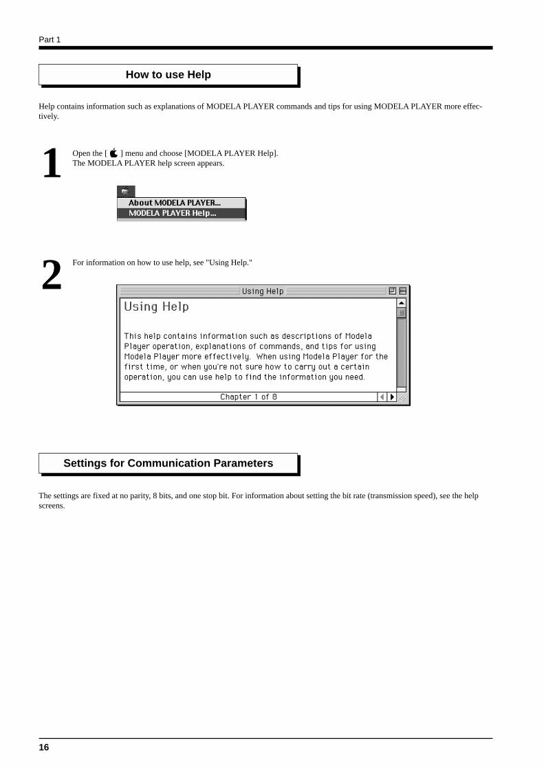
Open the [ ] menu and choose [MODELA PLAYER Help].The MODELA PLAYER help screen appears.1
For information on how to use help, see "Using Help."2
Help contains information such as explanations of MODELA PLAYER commands and tips for using MODELA PLAYER more effec-tively.
Settings for Communication Parameters
The settings are fixed at no parity, 8 bits, and one stop bit. For information about setting the bit rate (transmission speed), see the helpscreens.
Part 1
17
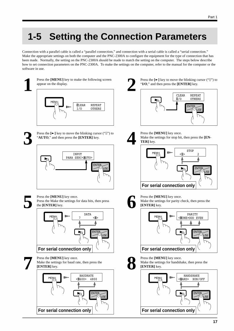
Press the [MENU] key to make the following screenappear on the display.1 Press the [ ] key to move the blinking cursor (“ ”) to
“I/O,” and then press the [ENTER] key.2
Press the [ ] key to move the blinking cursor (“ ”) to“AUTO,” and then press the [ENTER] key.3 Press the [MENU] key once.
Make the settings for stop bit, then press the [EN-TER] key.4
Press the [MENU] key once.Make the settings for parity check, then press the[ENTER] key.6Press the [MENU] key once.
Press the Make the settings for data bits, then pressthe [ENTER] key.5
For serial connection only
Press the [MENU] key once.Make the settings for handshake, then press the[ENTER] key.8Press the [MENU] key once.
Make the settings for baud rate, then press the[ENTER] key.7
For serial connection only
For serial connection only
For serial connection onlyFor serial connection only
1-5 Setting the Connection ParametersConnection with a parallel cable is called a “parallel connection,” and connection with a serial cable is called a “serial connection.”Make the appropriate settings on both the computer and the PNC-2300A to configure the equipment for the type of connection that hasbeen made. Normally, the setting on the PNC-2300A should be made to match the setting on the computer. The steps below describehow to set connection parameters on the PNC-2300A. To make the settings on the computer, refer to the manual for the computer or thesoftware in use.
Part 1
18
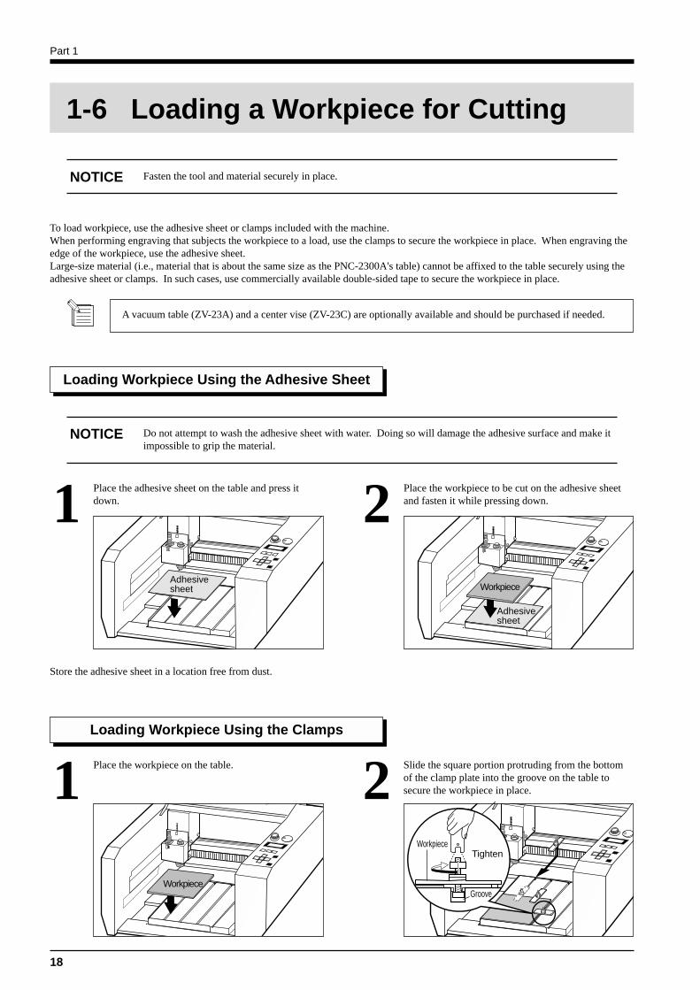
To load workpiece, use the adhesive sheet or clamps included with the machine.When performing engraving that subjects the workpiece to a load, use the clamps to secure the workpiece in place. When engraving theedge of the workpiece, use the adhesive sheet.Large-size material (i.e., material that is about the same size as the PNC-2300A's table) cannot be affixed to the table securely using theadhesive sheet or clamps. In such cases, use commercially available double-sided tape to secure the workpiece in place.
Loading Workpiece Using the Adhesive Sheet
Place the adhesive sheet on the table and press itdown.1 Place the workpiece to be cut on the adhesive sheet
and fasten it while pressing down.2Adhesivesheet
Adhesivesheet
Workpiece
Store the adhesive sheet in a location free from dust.
Loading Workpiece Using the Clamps
Place the workpiece on the table.1 Slide the square portion protruding from the bottomof the clamp plate into the groove on the table tosecure the workpiece in place.2
Workpiece
TightenWorkpiece
1-6 Loading a Workpiece for Cutting
Fasten the tool and material securely in place.NOTICE
A vacuum table (ZV-23A) and a center vise (ZV-23C) are optionally available and should be purchased if needed.
Do not attempt to wash the adhesive sheet with water. Doing so will damage the adhesive surface and make itimpossible to grip the material.
NOTICE
Groove
Part 1
19
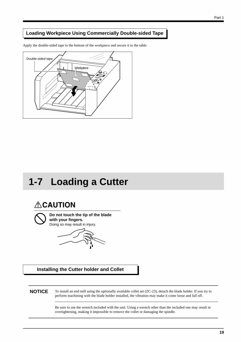
Loading Workpiece Using Commercially Double-sided Tape
Apply the double-sided tape to the bottom of the workpiece and secure it to the table.
Double-sided tape
Workpiece
1-7 Loading a Cutter
Installing the Cutter holder and Collet
Do not touch the tip of the bladewith your fingers.Doing so may result in injury.
NOTICE To install an end mill using the optionally available collet set (ZC-23), detach the blade holder. If you try toperform machining with the blade holder installed, the vibration may make it come loose and fall off.
Be sure to use the wrench included with the unit. Using a wrench other than the included one may result inovertightening, making it impossible to remove the collet or damaging the spindle.
Part 1
20
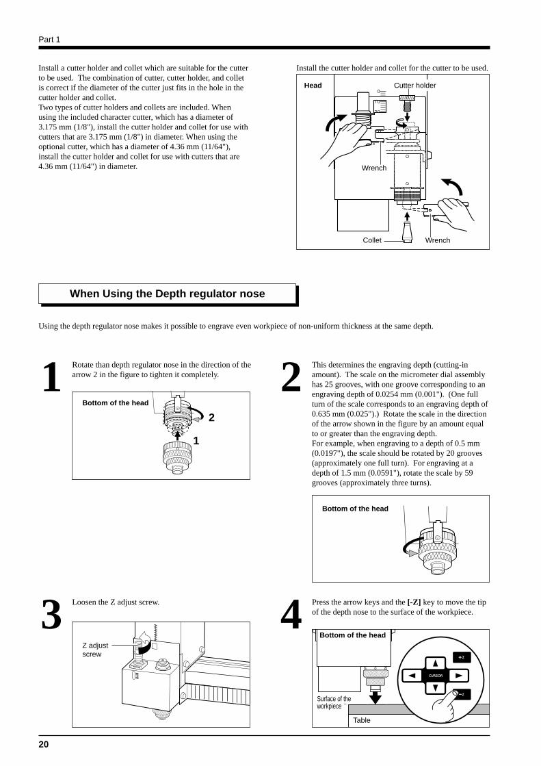
Install a cutter holder and collet which are suitable for the cutterto be used. The combination of cutter, cutter holder, and colletis correct if the diameter of the cutter just fits in the hole in thecutter holder and collet.Two types of cutter holders and collets are included. Whenusing the included character cutter, which has a diameter of3.175 mm (1/8"), install the cutter holder and collet for use withcutters that are 3.175 mm (1/8") in diameter. When using theoptional cutter, which has a diameter of 4.36 mm (11/64"),install the cutter holder and collet for use with cutters that are4.36 mm (11/64") in diameter.
Install the cutter holder and collet for the cutter to be used.
Head
Wrench
WrenchCollet
Cutter holder
When Using the Depth regulator nose
Using the depth regulator nose makes it possible to engrave even workpiece of non-uniform thickness at the same depth.
Rotate than depth regulator nose in the direction of thearrow 2 in the figure to tighten it completely.1 This determines the engraving depth (cutting-in
amount). The scale on the micrometer dial assemblyhas 25 grooves, with one groove corresponding to anengraving depth of 0.0254 mm (0.001"). (One fullturn of the scale corresponds to an engraving depth of0.635 mm (0.025").) Rotate the scale in the directionof the arrow shown in the figure by an amount equalto or greater than the engraving depth.For example, when engraving to a depth of 0.5 mm(0.0197"), the scale should be rotated by 20 grooves(approximately one full turn). For engraving at adepth of 1.5 mm (0.0591"), rotate the scale by 59grooves (approximately three turns).
2Bottom of the head
2
1
Bottom of the head
Loosen the Z adjust screw.3Z adjustscrew
Press the arrow keys and the [-Z] key to move the tipof the depth nose to the surface of the workpiece.4
Bottom of the head
Surface of theworkpiece
Table
Part 1
21
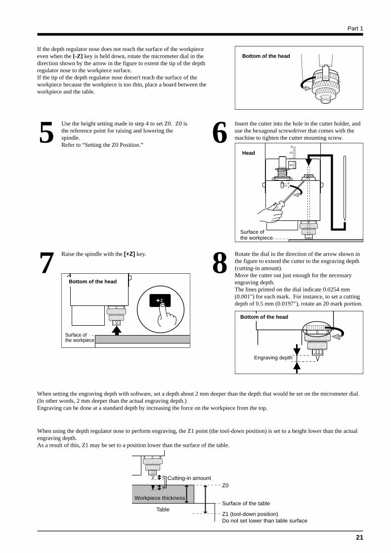
Bottom of the headIf the depth regulator nose does not reach the surface of the workpieceeven when the [-Z] key is held down, rotate the micrometer dial in thedirection shown by the arrow in the figure to extent the tip of the depthregulator nose to the workpiece surface.If the tip of the depth regulator nose doesn't reach the surface of theworkpiece because the workpiece is too thin, place a board between theworkpiece and the table.
Insert the cutter into the hole in the cutter holder, anduse the hexagonal screwdriver that comes with themachine to tighten the cutter mounting screw.6
Surface ofthe workpiece
Head
Use the height setting made in step 4 to set Z0. Z0 isthe reference point for raising and lowering thespindle.Refer to “Setting the Z0 Position.”
5
8
Bottom of the head
Rotate the dial in the direction of the arrow shown inthe figure to extend the cutter to the engraving depth(cutting-in amount).Move the cutter out just enough for the necessaryengraving depth.The lines printed on the dial indicate 0.0254 mm(0.001") for each mark. For instance, to set a cuttingdepth of 0.5 mm (0.0197"), rotate an 20 mark portion.
Engraving depth
Raise the spindle with the [+Z] key.7Bottom of the head
Surface ofthe workpiece
When setting the engraving depth with software, set a depth about 2 mm deeper than the depth that would be set on the micrometer dial.(In other words, 2 mm deeper than the actual engraving depth.)Engraving can be done at a standard depth by increasing the force on the workpiece from the top.
When using the depth regulator nose to perform engraving, the Z1 point (the tool-down position) is set to a height lower than the actualengraving depth.As a result of this, Z1 may be set to a position lower than the surface of the table.
Z0
Surface of the table
Z1 (tool-down position)Do not set lower than table surface
Workpiece thickness
Table
Cutting-in amount
Part 1
22
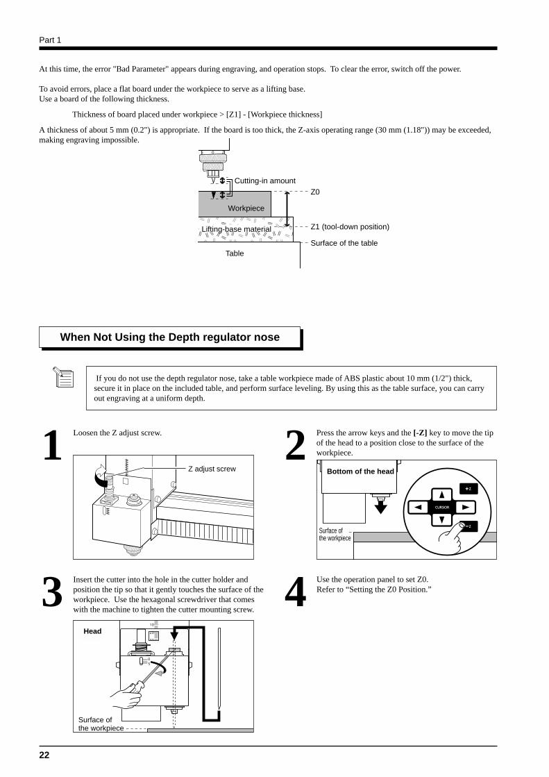
Loosen the Z adjust screw.1 Press the arrow keys and the [-Z] key to move the tipof the head to a position close to the surface of theworkpiece.2
Z adjust screw Bottom of the head
Surface ofthe workpiece
When Not Using the Depth regulator nose
If you do not use the depth regulator nose, take a table workpiece made of ABS plastic about 10 mm (1/2") thick,secure it in place on the included table, and perform surface leveling. By using this as the table surface, you can carryout engraving at a uniform depth.
Insert the cutter into the hole in the cutter holder andposition the tip so that it gently touches the surface of theworkpiece. Use the hexagonal screwdriver that comeswith the machine to tighten the cutter mounting screw.
Use the operation panel to set Z0.Refer to “Setting the Z0 Position.”43
Surface ofthe workpiece
Head
At this time, the error "Bad Parameter" appears during engraving, and operation stops. To clear the error, switch off the power.
To avoid errors, place a flat board under the workpiece to serve as a lifting base.Use a board of the following thickness.
Thickness of board placed under workpiece > [Z1] - [Workpiece thickness]
A thickness of about 5 mm (0.2") is appropriate. If the board is too thick, the Z-axis operating range (30 mm (1.18")) may be exceeded,making engraving impossible.
Z0
Surface of the table
Z1 (tool-down position)
Workpiece
Table
Cutting-in amount
Lifting-base material
Part 1
23
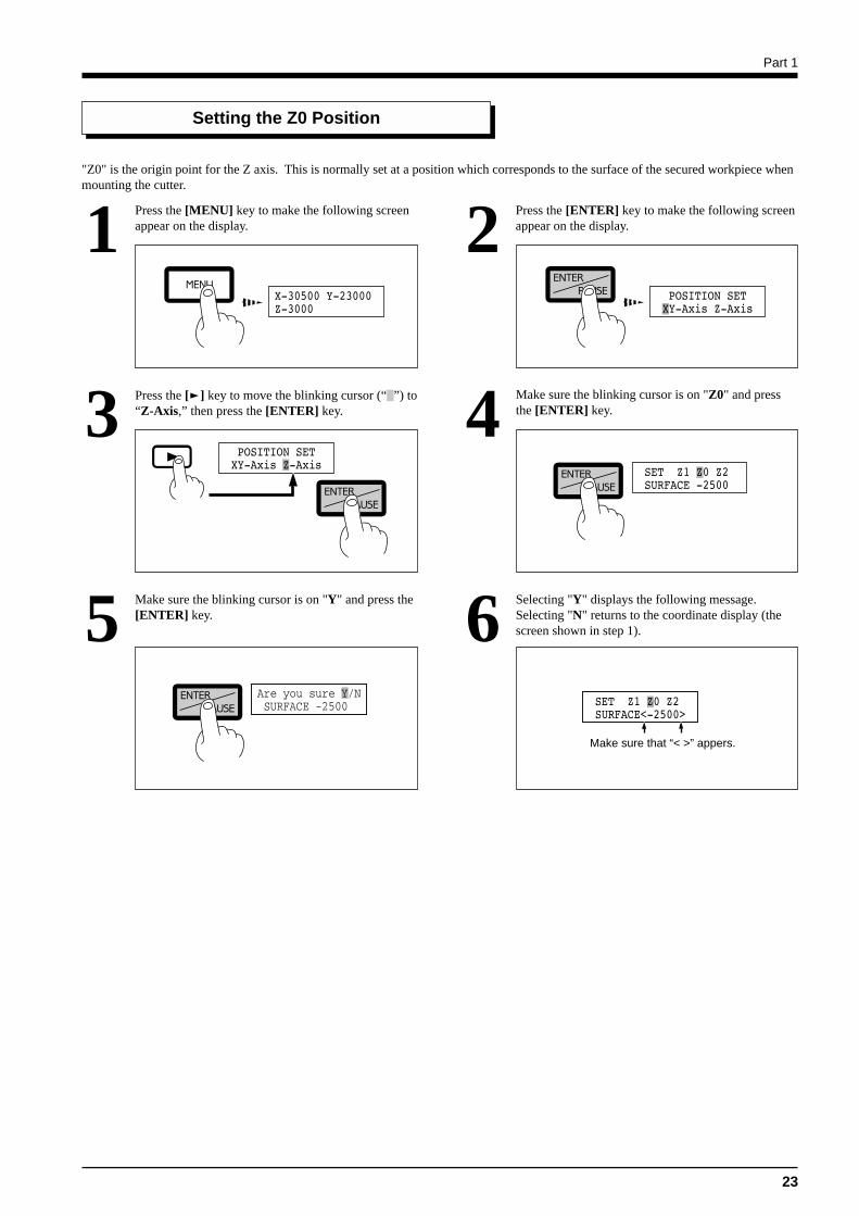
Setting the Z0 Position
"Z0" is the origin point for the Z axis. This is normally set at a position which corresponds to the surface of the secured workpiece whenmounting the cutter.
Press the [MENU] key to make the following screenappear on the display.1 Press the [ENTER] key to make the following screen
appear on the display.2
Press the [ ] key to move the blinking cursor (“ ”) to“Z-Axis,” then press the [ENTER] key.3 Make sure the blinking cursor is on "Z0" and press
the [ENTER] key.4
Make sure the blinking cursor is on "Y" and press the[ENTER] key.5 Selecting "Y" displays the following message.
Selecting "N" returns to the coordinate display (thescreen shown in step 1).6
Make sure that “< >” appers.
Part 1
24
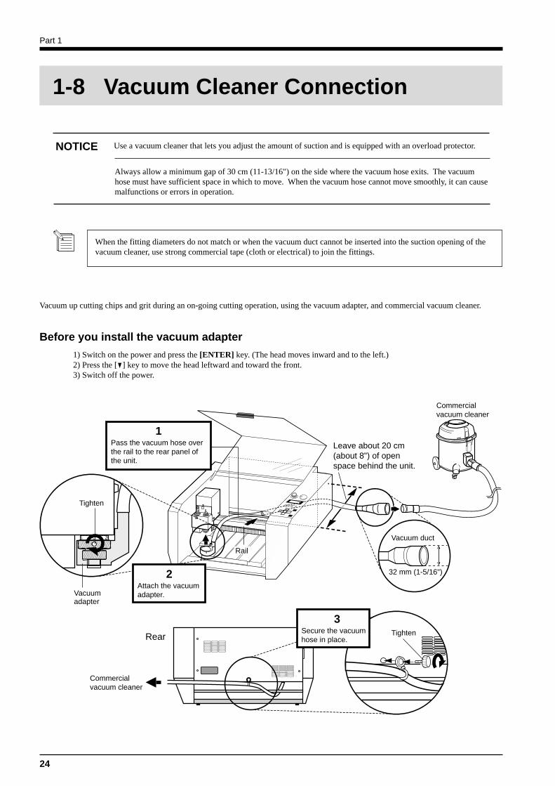
1-8 Vacuum Cleaner Connection
NOTICE Use a vacuum cleaner that lets you adjust the amount of suction and is equipped with an overload protector.
Always allow a minimum gap of 30 cm (11-13/16") on the side where the vacuum hose exits. The vacuumhose must have sufficient space in which to move. When the vacuum hose cannot move smoothly, it can causemalfunctions or errors in operation.
When the fitting diameters do not match or when the vacuum duct cannot be inserted into the suction opening of thevacuum cleaner, use strong commercial tape (cloth or electrical) to join the fittings.
Vacuum up cutting chips and grit during an on-going cutting operation, using the vacuum adapter, and commercial vacuum cleaner.
Before you install the vacuum adapter
1) Switch on the power and press the [ENTER] key. (The head moves inward and to the left.)2) Press the [ ] key to move the head leftward and toward the front.3) Switch off the power.
Commercialvacuum cleaner
Vacuumadapter
Rear Tighten
Rail
1Pass the vacuum hose overthe rail to the rear panel ofthe unit.
Tighten
2Attach the vacuumadapter.
3Secure the vacuumhose in place.
Vacuum duct
32 mm (1-5/16")
Commercialvacuum cleaner
Leave about 20 cm(about 8") of openspace behind the unit.
Part 1
25
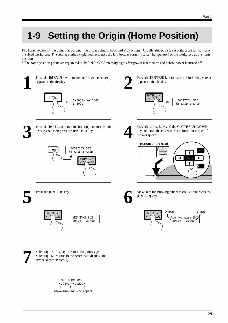
The home position is the point that becomes the origin point in the X and Y directions. Usually, this point is set at the front left corner ofthe fixed workpiece. The setting method explained here, uses the left, bottom corner (nearest the operator) of the workpiece as the homeposition.* The home position points are registered in the PNC-2300A memory right after power is turned on and before power is turned off.
Press the [MENU] key to make the following screenappear on the display.1 Press the [ENTER] key to make the following screen
appear on the display.2
Press the [ ] key to move the blinking cursor (“ ”) to“XY-Axis,” then press the [ENTER] key.3 Press the arrow keys and the CUTTER UP/DOWN
keys to move the cutter with the front left corner ofthe workpiece.4
Press the [ENTER] key.5
Bottom of the head
1-9 Setting the Origin (Home Position)
Make sure the blinking cursor is on "Y" and press the[ENTER] key.6
X axis Y axis
Selecting "Y" displays the following message.Selecting "N" returns to the coordinate display (thescreen shown in step 1).7
Make sure that “< >” appers.
Part 1
26
Before you begin the actual cutting process, the cutting conditions such as the revolution speed of the spindle motor and the feedingspeed of each axis must be designated according to the quality of the workpiece and the type of cutter used. There are several decidingfactors to be taken into account when designating the cutting conditions.
1. The quality of the workpiece 4. The cutting method2. The type of cutter used 5. The cutting shape3. The diameter of the cutter used
Designate the cutting conditions in consideration of the above factors by performing the following three PNC-2300A setting operations.
1. The spindle motor revolution speed (cutter revolution speed)2. The feeding speed (cutter moving speed)3. The cutting-in amount (depth of one cutting operation)Note : When settings have been made with both the software and the PNC-2300A, the last settings made have priority.
In this manual, these three conditions are called the cutting conditions. The characteristics and points to consider for each of theseconditions are as follows.
Manual Setting of Cutting Conditions
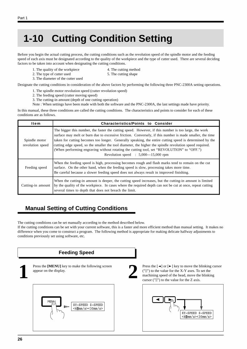
Press the [MENU] key to make the following screenappear on the display.1 Press the [ ] or [ ] key to move the blinking cursor
(" ") to the value for the X-Y axes. To set themachining speed of the head, move the blinkingcursor (" ") to the value for the Z axis.
2Feeding Speed
1-10 Cutting Condition Setting
The cutting conditions can be set manually according to the method described below.If the cutting conditions can be set with your current software, this is a faster and more efficient method than manual setting. It makes nodifference when you come to construct a program. The following method is appropriate for making delicate halfway adjustments toconditions previously set using software, etc.
I t em Characteristics/Points to Consider
The bigger this number, the faster the cutting speed. However, if this number is too large, the work surface may melt or burn due to excessive friction. Conversely, if this number is made smaller, the time
Spindle motor taken for cutting becomes too longer. Generally speaking, the entire cutting speed is determined by the revolution speed cutting edge speed, so the smaller the tool diameter, the higher the spindle revolution speed required.
(When performing engraving without rotating the cutting tool, set “REVOLUTION” to “OFF.”)Revolution speed : 5,000—15,000 rpm
When the feeding speed is high, processing becomes rough and flash marks tend to remain on the cut Feeding speed surface. On the other hand, when the feeding speed is slow, processing takes more time.
Be careful because a slower feeding speed does not always result in improved finishing.
When the cutting-in amount is deeper, the cutting speed increases, but the cutting-in amount is limited Cutting-in amount by the quality of the workpiece. In cases where the required depth can not be cut at once, repeat cutting
several times to depth that does not breach the limit.
Part 1
27
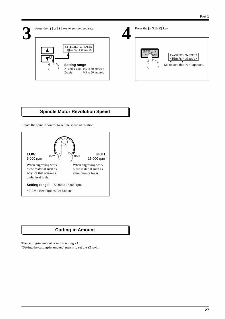
Press the [ ] or [ ] key to set the feed rate.3 Press the [ENTER] key.4
The cutting-in amount is set by setting Z1.“Setting the cutting-in amount” means to set the Z1 point.
Make sure that “< >” appears.Setting rangeX- and Y-axis : 0.5 to 60 mm/secZ-axis : 0.5 to 30 mm/sec
Spindle Motor Revolution Speed
Rotate the spindle control to set the speed of rotation.
Setting range: 5,000 to 15,000 rpm
* RPM : Revolutions Per Minute
LOW5,000 rpm
When engraving workpiece material such asacrylics that weakensunder heat high.
HIGH15,000 rpm
When engraving workpiece material such asaluminum or brass.
Cutting-in Amount
Part 1
28
Cutting Condition Setting Examples
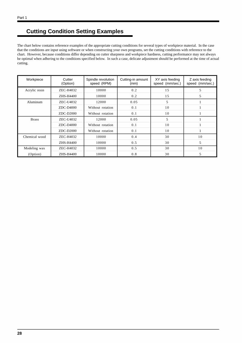
The chart below contains reference examples of the appropriate cutting conditions for several types of workpiece material. In the casethat the conditions are input using software or when constructing your own programs, set the cutting conditions with reference to thechart. However, because conditions differ depending on cutter sharpness and workpiece hardness, cutting performance may not alwaysbe optimal when adhering to the conditions specified below. In such a case, delicate adjustment should be performed at the time of actualcutting.
Workpiece Cutter Spindle revolution Cutting-in amount XY axis feeding Z axis feeding(Option) speed (RPM) (mm) speed (mm/sec.) speed (mm/sec.)
Acrylic resin ZEC-H4032 10000 0.2 15 5
ZHS-H4400 10000 0.2 15 5
Aluminum ZEC-U4032 12000 0.05 5 1
ZDC-D4000 Without rotation 0.1 10 1
ZDC-D2000 Without rotation 0.1 10 1
Brass ZEC-U4032 12000 0.05 5 1
ZDC-D4000 Without rotation 0.1 10 1
ZDC-D2000 Without rotation 0.1 10 1
Chemical wood ZEC-H4032 10000 0.4 30 10
ZHS-H4400 10000 0.5 30 5
Modeling wax ZEC-H4032 10000 0.5 30 10
(Option) ZHS-H4400 10000 0.8 30 5
Part 1
29
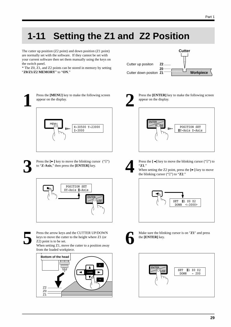
The cutter up position (Z2 point) and down position (Z1 point)are normally set with the software. If they cannot be set withyour current software then set them manually using the keys onthe switch panel.* The Z0, Z1, and Z2 points can be stored in memory by setting“Z0/Z1/Z2 MEMORY” to “ON.”
1-11 Setting the Z1 and Z2 Position
WorkpieceZ0Z2Cutter up positon
Cutter down positon Z1
Cutter
Press the [MENU] key to make the following screenappear on the display.1 Press the [ENTER] key to make the following screen
appear on the display.2
Press the [ ] key to move the blinking cursor (“ ”)to “Z-Axis,” then press the [ENTER] key.3 Press the [ ] key to move the blinking cursor (“ ”) to
“Z1.”When setting the Z2 point, press the [ ] key to movethe blinking cursor (“ ”) to “Z2.”
4
Press the arrow keys and the CUTTER UP/DOWNkeys to move the cutter to the height where Z1 (orZ2) point is to be set.When setting Z1, move the cutter to a position awayfrom the loaded workpiece.
5 Make sure the blinking cursor is on "Z1" and pressthe [ENTER] key.6
Z2Z0Z1
Bottom of the head
Part 1
30
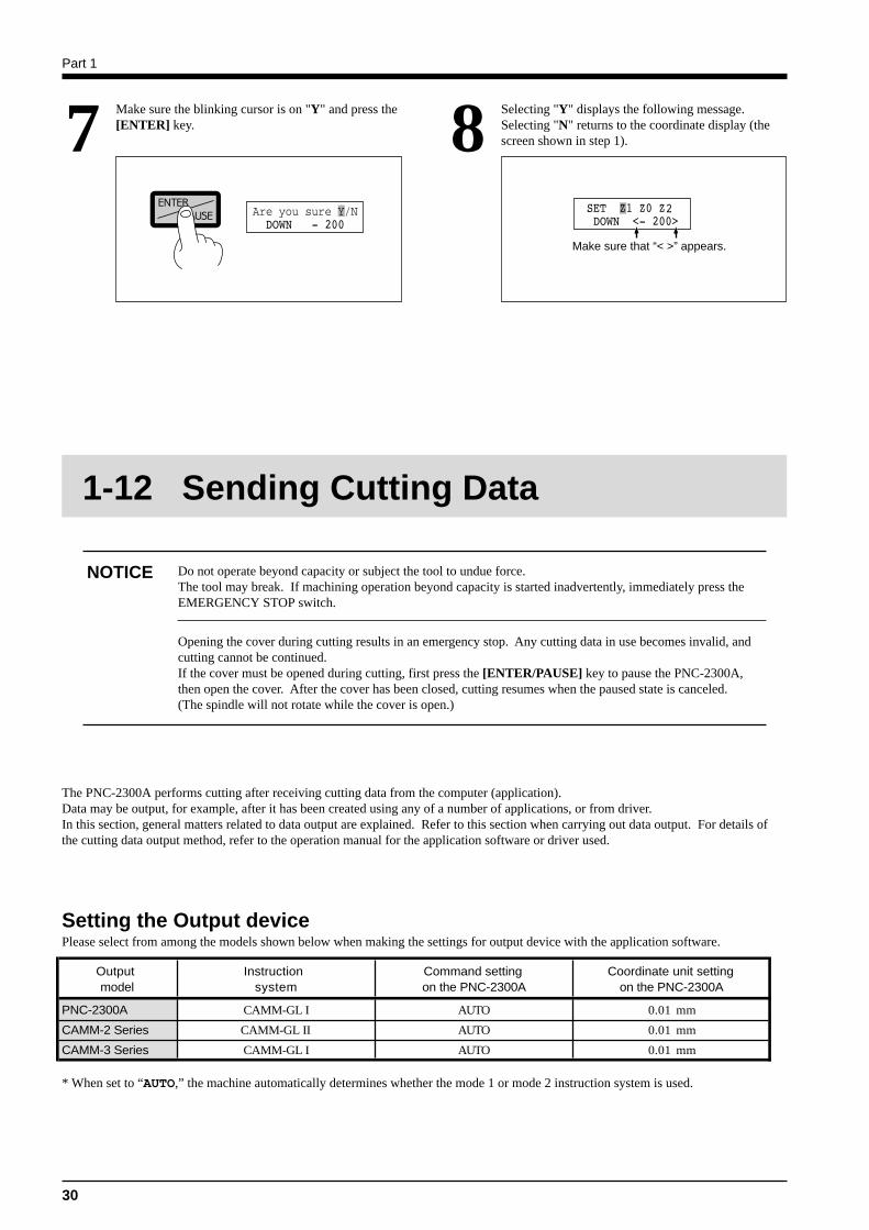
Make sure the blinking cursor is on "Y" and press the[ENTER] key.7 Selecting "Y" displays the following message.
Selecting "N" returns to the coordinate display (thescreen shown in step 1).8
Make sure that “< >” appears.
1-12 Sending Cutting Data
* When set to “AUTO,” the machine automatically determines whether the mode 1 or mode 2 instruction system is used.
The PNC-2300A performs cutting after receiving cutting data from the computer (application).Data may be output, for example, after it has been created using any of a number of applications, or from driver.In this section, general matters related to data output are explained. Refer to this section when carrying out data output. For details ofthe cutting data output method, refer to the operation manual for the application software or driver used.
Do not operate beyond capacity or subject the tool to undue force.The tool may break. If machining operation beyond capacity is started inadvertently, immediately press theEMERGENCY STOP switch.
Opening the cover during cutting results in an emergency stop. Any cutting data in use becomes invalid, andcutting cannot be continued.If the cover must be opened during cutting, first press the [ENTER/PAUSE] key to pause the PNC-2300A,then open the cover. After the cover has been closed, cutting resumes when the paused state is canceled.(The spindle will not rotate while the cover is open.)
NOTICE
Setting the Output devicePlease select from among the models shown below when making the settings for output device with the application software.
Output Instruction Command setting Coordinate unit setting model system on the PNC-2300A on the PNC-2300A
PNC-2300A CAMM-GL I AUTO 0.01 mm
CAMM-2 Series CAMM-GL II AUTO 0.01 mm
CAMM-3 Series CAMM-GL I AUTO 0.01 mm
Part 1
31
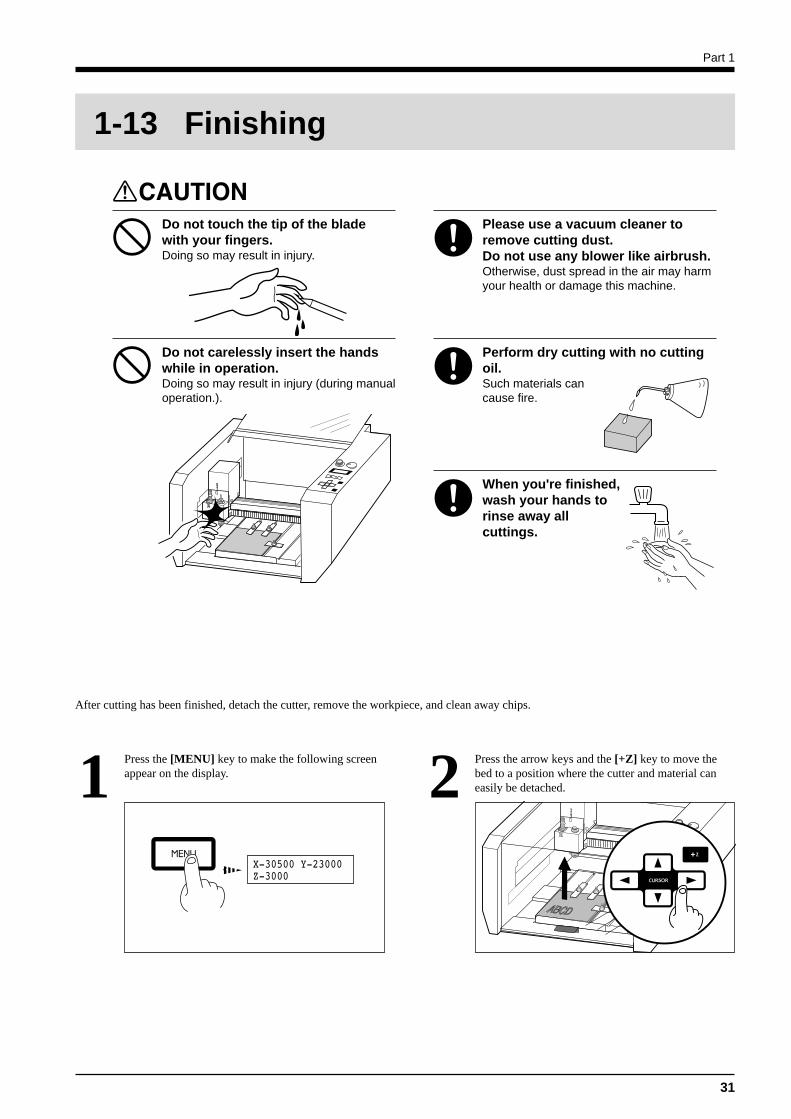
1-13 Finishing
Do not touch the tip of the bladewith your fingers.Doing so may result in injury.
Please use a vacuum cleaner toremove cutting dust.Do not use any blower like airbrush.Otherwise, dust spread in the air may harmyour health or damage this machine.
Do not carelessly insert the handswhile in operation.Doing so may result in injury (during manualoperation.).
Perform dry cutting with no cuttingoil.Such materials cancause fire.
When you're finished,wash your hands torinse away allcuttings.
Press the [MENU] key to make the following screenappear on the display.1 Press the arrow keys and the [+Z] key to move the
bed to a position where the cutter and material caneasily be detached.2
After cutting has been finished, detach the cutter, remove the workpiece, and clean away chips.
Part 1
32
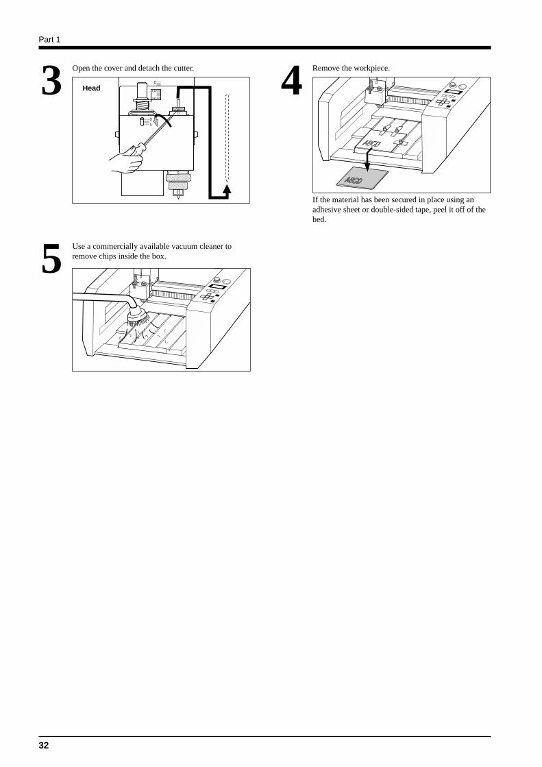
Open the cover and detach the cutter.3 Remove the workpiece.4Head
Use a commercially available vacuum cleaner toremove chips inside the box.5
If the material has been secured in place using anadhesive sheet or double-sided tape, peel it off of thebed.
Part 2
33
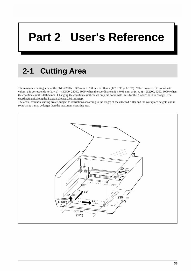
The maximum cutting area of the PNC-2300A is 305 mm 230 mm 30 mm (12" 9" 1-1/8"). When converted to coordinatevalues, this corresponds to (x, y, z) = (30500, 23000, 3000) when the coordinate unit is 0.01 mm, or (x, y, z) = (12200, 9200, 3000) whenthe coordinate unit is 0.025 mm. Changing the coordinate unit causes only the coordinate units for the X and Y axes to change. Thecoordinate unit along the Z axis is always 0.01 mm/step.The actual available cutting area is subject to restrictions according to the length of the attached cutter and the workpiece height; and insome cases it may be larger than the maximum operating area.
+Y
+X
+Z230 mm
(9")
305 mm(12")
30 mm(1-1/8")
Part 2 User's Reference
2-1 Cutting Area
Part 2
34
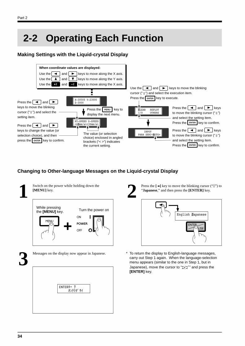
Making Settings with the Liquid-crystal Display
Changing to Other-language Messages on the Liquid-crystal Display
Switch on the power while holding down the[MENU] key.1 Press the [ ] key to move the blinking cursor (“ ”) to
“Japanese,” and then press the [ENTER] key.2
Messages on the display now appear in Japanese.3 * To return the display to English-language messages,carry out Step 1 again. When the language-selectionmenu appears (similar to the one in Step 1, but inJapanese), move the cursor to “ ” and press the[ENTER] key.
2-2 Operating Each Function
When coordinate values are displayed:
Use the and keys to move along the X axis.
Use the and keys to move along the Y axis.
Use the and keys to move along the X axis.
Press the and
keys to move the blinking
cursor (“ ”) and select the
setting item.
Press the and
keys to change the value (or
selection choice), and then
press the key to confirm.
Press the key to
display the next menu.
The value (or selection choice) enclosed in angled brackets (“< >”) indicates the current setting.
Use the and keys to move the blinking
cursor (“ ”) and select the execution item.
Press the key to execute.
Press the and keys
to move the blinking cursor (“ ”)
and select the setting item.
Press the key to confirm.
Press the and keys
to move the blinking cursor (“ ”)
and select the setting item.
Press the key to confirm.
While pressingthe [MENU] key.
+Turn the power on
Part 2
35
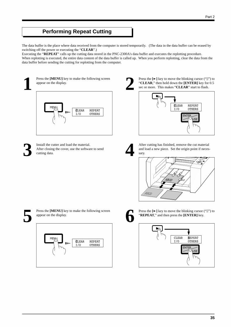
Performing Repeat Cutting
The data buffer is the place where data received from the computer is stored temporarily. (The data in the data buffer can be erased byswitching off the power or executing the “CLEAR”.)Executing the “REPEAT” calls up the cutting data stored in the PNC-2300A's data buffer and executes the replotting procedure.When replotting is executed, the entire data content of the data buffer is called up. When you perform replotting, clear the data from thedata buffer before sending the cutting for replotting from the computer.
Press the [MENU] key to make the following screenappear on the display.1 Press the [ ] key to move the blinking cursor (“ ”) to
“CLEAR,” then hold down the [ENTER] key for 0.5sec or more. This makes “CLEAR” start to flash.2
Install the cutter and load the material.After closing the cover, use the software to sendcutting data.3 After cutting has finished, remove the cut material
and load a new piece. Set the origin point if neces-sary.4
Press the [MENU] key to make the following screenappear on the display.5 Press the [ ] key to move the blinking cursor (“ ”) to
“REPEAT,” and then press the [ENTER] key.6
Part 2
36
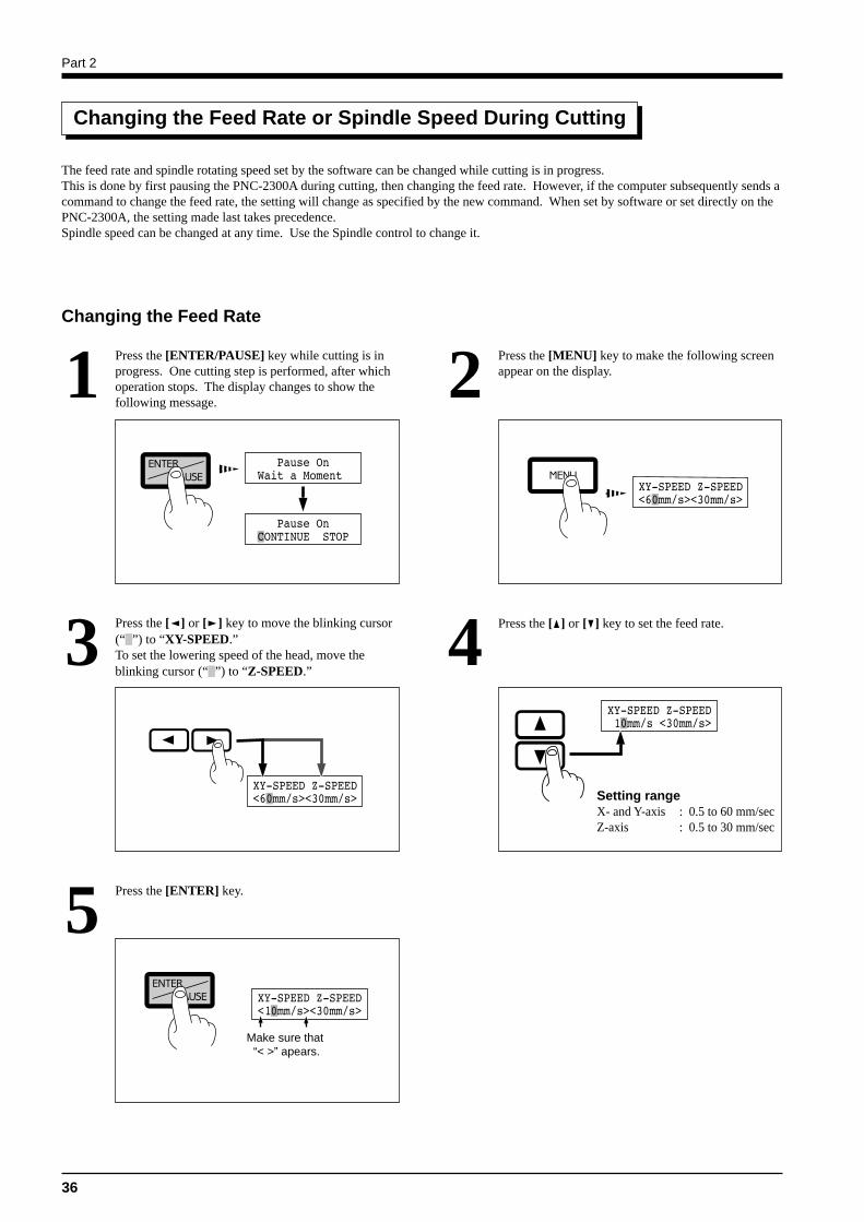
Changing the Feed Rate or Spindle Speed During Cutting
The feed rate and spindle rotating speed set by the software can be changed while cutting is in progress.This is done by first pausing the PNC-2300A during cutting, then changing the feed rate. However, if the computer subsequently sends acommand to change the feed rate, the setting will change as specified by the new command. When set by software or set directly on thePNC-2300A, the setting made last takes precedence.Spindle speed can be changed at any time. Use the Spindle control to change it.
Changing the Feed Rate
Press the [ENTER/PAUSE] key while cutting is inprogress. One cutting step is performed, after whichoperation stops. The display changes to show thefollowing message.
1
Press the [ ] or [ ] key to move the blinking cursor(“ ”) to “XY-SPEED.”To set the lowering speed of the head, move theblinking cursor (“ ”) to “Z-SPEED.”
3
Press the [MENU] key to make the following screenappear on the display.2
Press the [ ] or [ ] key to set the feed rate.4
Setting rangeX- and Y-axis : 0.5 to 60 mm/secZ-axis : 0.5 to 30 mm/sec
Press the [ENTER] key.5
Make sure that “< >” apears.
Part 2
37
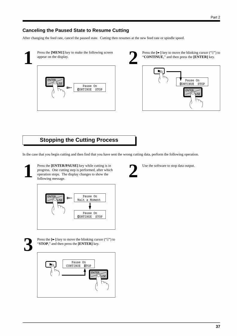
Canceling the Paused State to Resume Cutting
After changing the feed rate, cancel the paused state. Cutting then resumes at the new feed rate or spindle speed.
Press the [MENU] key to make the following screenappear on the display.1 Press the [ ] key to move the blinking cursor (“ ”) to
“CONTINUE,” and then press the [ENTER] key.2
In the case that you begin cutting and then find that you have sent the wrong cutting data, perform the following operation.
Stopping the Cutting Process
Press the [ENTER/PAUSE] key while cutting is inprogress. One cutting step is performed, after whichoperation stops. The display changes to show thefollowing message.
1 Use the software to stop data output.2
Press the [ ] key to move the blinking cursor (“ ”) to“STOP,” and then press the [ENTER] key.3
Part 2
38
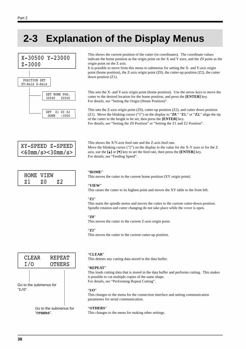
This shows the current position of the cutter (in coordinates). The coordinate valuesindicate the home position as the origin point on the X and Y axes, and the Z0 point as theorigin point on the Z axis.It is possible to move from this menu to submenus for setting the X- and Y-axis originpoint (home position), the Z-axis origin point (Z0), the cutter-up position (Z2), the cutterdown position (Z1).
This sets the X- and Y-axis origin point (home position). Use the arrow keys to move thecutter to the desired location for the home position, and press the [ENTER] key.For details, see “Setting the Origin (Home Position)”.
This sets the Z-axis origin point (Z0), cutter-up position (Z2), and cutter down position(Z1). Move the blinking cursor (“ ”) on the display to “Z0,” “Z1,” or “Z2,” align the tipof the cutter to the height to be set, then press the [ENTER] key.For details, see “Setting the Z0 Position” or “Setting the Z1 and Z2 Position”.
This shows the X/Y-axis feed rate and the Z-axis feed rate.Move the blinking cursor (" ") on the display to the value for the X-Y axes or for the Zaxis, use the [ ] or [ ] key to set the feed rate, then press the [ENTER] key.For details, see “Feeding Speed”.
“HOME”This moves the cutter to the current home position (XY origin point).
“VIEW”This raises the cutter to its highest point and moves the XY table to the front left.
“Z1”This starts the spindle motor and moves the cutter to the current cutter-down position.Spindle rotation and cutter changing do not take place while the cover is open.
“Z0”This moves the cutter to the current Z-axis origin point.
“Z2”This moves the cutter to the current cutter-up position.
“CLEAR”This deletes any cutting data stored in the data buffer.
“REPEAT”This loads cutting data that is stored in the data buffer and performs cutting. This makesit possible to cut multiple copies of the same shape.For details, see “Performing Repeat Cutting”.
“I/O”This changes to the menu for the connection interface and setting communicationparameters for serial communication.
“OTHERS”This changes to the menu for making other settings.
Go to the submenus for“OTHERS”.
Go to the submenus for“I/O”.
2-3 Explanation of the Display Menus
Part 2
39
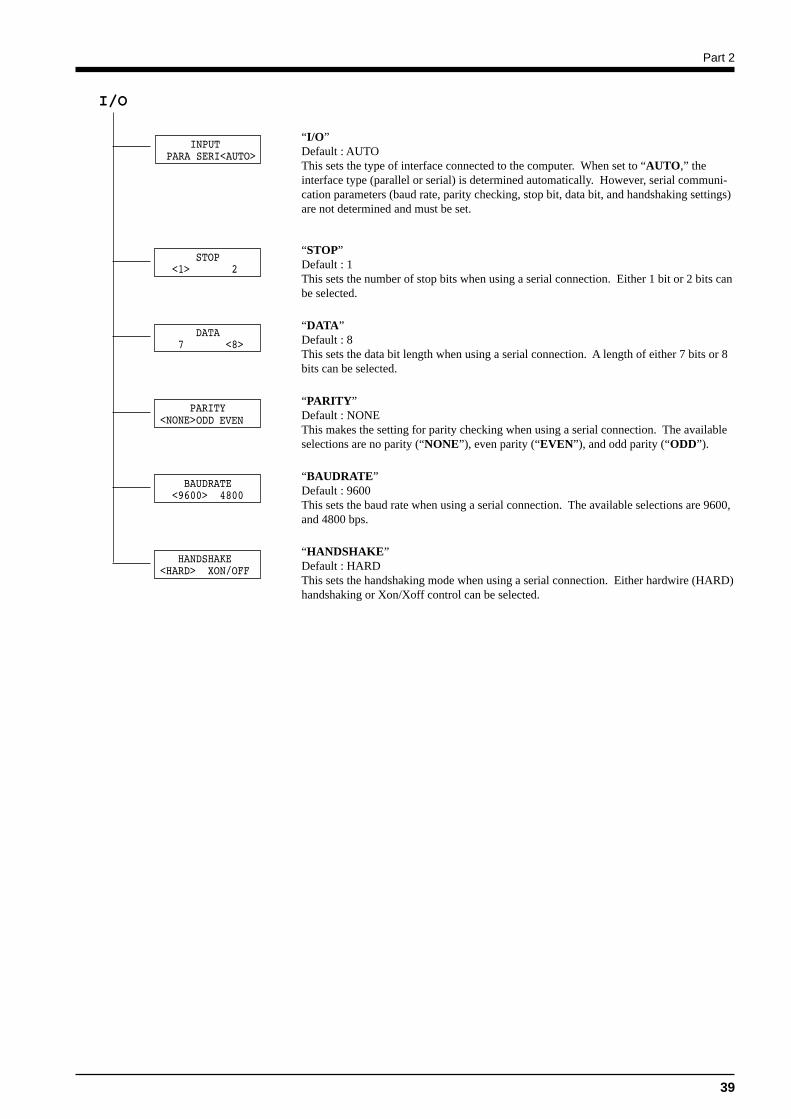
“I/O”Default : AUTOThis sets the type of interface connected to the computer. When set to “AUTO,” theinterface type (parallel or serial) is determined automatically. However, serial communi-cation parameters (baud rate, parity checking, stop bit, data bit, and handshaking settings)are not determined and must be set.
I/O
“STOP”Default : 1This sets the number of stop bits when using a serial connection. Either 1 bit or 2 bits canbe selected.
“DATA”Default : 8This sets the data bit length when using a serial connection. A length of either 7 bits or 8bits can be selected.
“PARITY”Default : NONEThis makes the setting for parity checking when using a serial connection. The availableselections are no parity (“NONE”), even parity (“EVEN”), and odd parity (“ODD”).
“BAUDRATE”Default : 9600This sets the baud rate when using a serial connection. The available selections are 9600,and 4800 bps.
“HANDSHAKE”Default : HARDThis sets the handshaking mode when using a serial connection. Either hardwire (HARD)handshaking or Xon/Xoff control can be selected.
Part 2
40
OTHERS
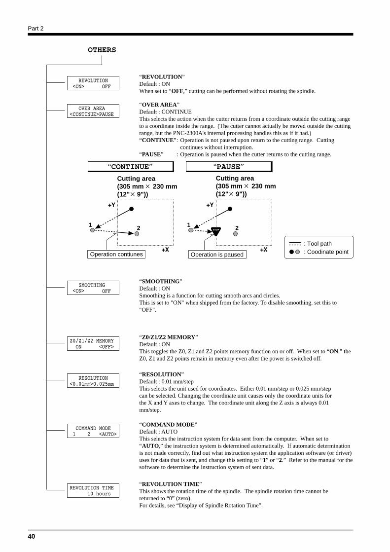
“REVOLUTION”Default : ONWhen set to “OFF,” cutting can be performed without rotating the spindle.
“OVER AREA”Default : CONTINUEThis selects the action when the cutter returns from a coordinate outside the cutting rangeto a coordinate inside the range. (The cutter cannot actually be moved outside the cuttingrange, but the PNC-2300A's internal processing handles this as if it had.)“CONTINUE”: Operation is not paused upon return to the cutting range. Cutting
continues without interruption.“PAUSE” : Operation is paused when the cutter returns to the cutting range.
“SMOOTHING”Default : ONSmoothing is a function for cutting smooth arcs and circles.This is set to "ON" when shipped from the factory. To disable smoothing, set this to"OFF".
“Z0/Z1/Z2 MEMORY”Default : ONThis toggles the Z0, Z1 and Z2 points memory function on or off. When set to “ON,” theZ0, Z1 and Z2 points remain in memory even after the power is switched off.
“RESOLUTION”Default : 0.01 mm/stepThis selects the unit used for coordinates. Either 0.01 mm/step or 0.025 mm/stepcan be selected. Changing the coordinate unit causes only the coordinate units forthe X and Y axes to change. The coordinate unit along the Z axis is always 0.01mm/step.
“COMMAND MODE”Default : AUTOThis selects the instruction system for data sent from the computer. When set to“AUTO,” the instruction system is determined automatically. If automatic determinationis not made correctly, find out what instruction system the application software (or driver)uses for data that is sent, and change this setting to “1” or “2.” Refer to the manual for thesoftware to determine the instruction system of sent data.
“REVOLUTION TIME”This shows the rotation time of the spindle. The spindle rotation time cannot bereturned to “0” (zero).For details, see “Display of Spindle Rotation Time”.
1 2 1 2
Operation is pausedOperation contiunes
: Tool path: Coodinate point
“CONTINUE” “PAUSE”
Cutting area(305 mm 230 mm (12" 9"))
Cutting area(305 mm 230 mm (12" 9"))
Part 2
41
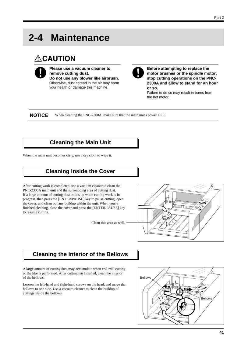
After cutting work is completed, use a vacuum cleaner to clean thePNC-2300A main unit and the surrounding area of cutting dust.If a large amount of cutting dust builds up while cutting work is inprogress, then press the [ENTER/PAUSE] key to pause cutting, openthe cover, and clean out any buildup within the unit. When you'refinished cleaning, close the cover and press the [ENTER/PAUSE] keyto resume cutting.
2-4 Maintenance
Please use a vacuum cleaner toremove cutting dust.Do not use any blower like airbrush.Otherwise, dust spread in the air may harmyour health or damage this machine.
Before attempting to replace themotor brushes or the spindle motor,stop cutting operations on the PNC-2300A and allow to stand for an houror so.Failure to do so may result in burns fromthe hot motor.
Cleaning the Main Unit
When the main unit becomes dirty, use a dry cloth to wipe it.
Cleaning Inside the Cover
A large amount of cutting dust may accumulate when end-mill cuttingor the like is performed. After cutting has finished, clean the interiorof the bellows.
Loosen the left-hand and right-hand screws on the head, and move thebellows to one side. Use a vacuum cleaner to clean the buildup ofcuttings inside the bellows.
Cleaning the Interior of the Bellows
Clean this area as well.
Bellows
Bellows
When cleaning the PNC-2300A, make sure that the main unit's power OFF.NOTICE
Part 2
42
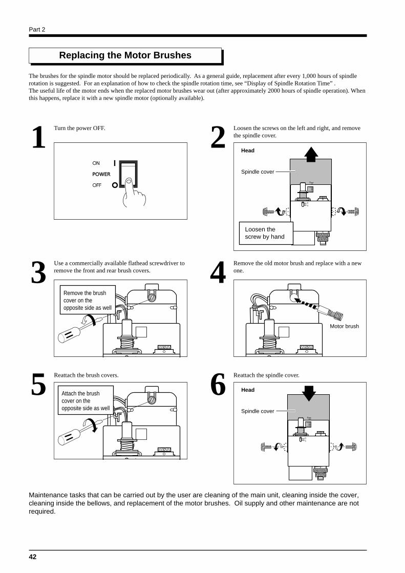
Turn the power OFF.1 Loosen the screws on the left and right, and removethe spindle cover.2
Use a commercially available flathead screwdriver toremove the front and rear brush covers.3 Remove the old motor brush and replace with a new
one.4
Head
Replacing the Motor Brushes
The brushes for the spindle motor should be replaced periodically. As a general guide, replacement after every 1,000 hours of spindlerotation is suggested. For an explanation of how to check the spindle rotation time, see “Display of Spindle Rotation Time” .The useful life of the motor ends when the replaced motor brushes wear out (after approximately 2000 hours of spindle operation). Whenthis happens, replace it with a new spindle motor (optionally available).
Loosen thescrew by hand
Spindle cover
Remove the brushcover on theopposite side as well
Motor brush
Reattach the brush covers.5 Reattach the spindle cover.6
Maintenance tasks that can be carried out by the user are cleaning of the main unit, cleaning inside the cover,cleaning inside the bellows, and replacement of the motor brushes. Oil supply and other maintenance are notrequired.
Attach the brushcover on theopposite side as well
Head
Spindle cover
Part 2
43
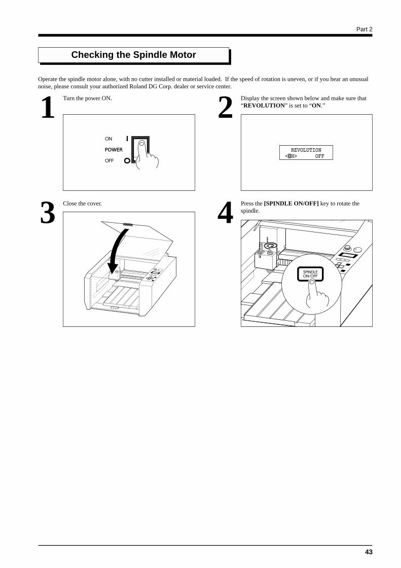
Operate the spindle motor alone, with no cutter installed or material loaded. If the speed of rotation is uneven, or if you hear an unusualnoise, please consult your authorized Roland DG Corp. dealer or service center.
Checking the Spindle Motor
Turn the power ON.1 Display the screen shown below and make sure that“REVOLUTION” is set to “ON.”2
Close the cover.3 Press the [SPINDLE ON/OFF] key to rotate thespindle.4
Part 2
44
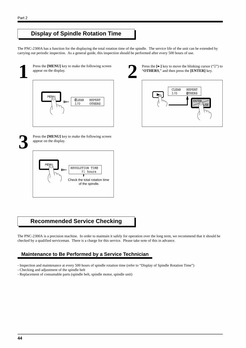
Display of Spindle Rotation Time
The PNC-2300A has a function for the displaying the total rotation time of the spindle. The service life of the unit can be extended bycarrying out periodic inspection. As a general guide, this inspection should be performed after every 500 hours of use.
Press the [MENU] key to make the following screenappear on the display.1 Press the [ ] key to move the blinking cursor (“ ”) to
“OTHERS,” and then press the [ENTER] key.2
Press the [MENU] key to make the following screenappear on the display.3
- Inspection and maintenance at every 500 hours of spindle rotation time (refer to “Display of Spindle Rotation Time”)- Checking and adjustment of the spindle belt- Replacement of consumable parts (spindle belt, spindle motor, spindle unit)
Recommended Service Checking
The PNC-2300A is a precision machine. In order to maintain it safely for operation over the long term, we recommend that it should bechecked by a qualified serviceman. There is a charge for this service. Please take note of this in advance.
Maintenance to Be Performed by a Service Technician
Check the total rotation time of the spindle.
Part 2
45
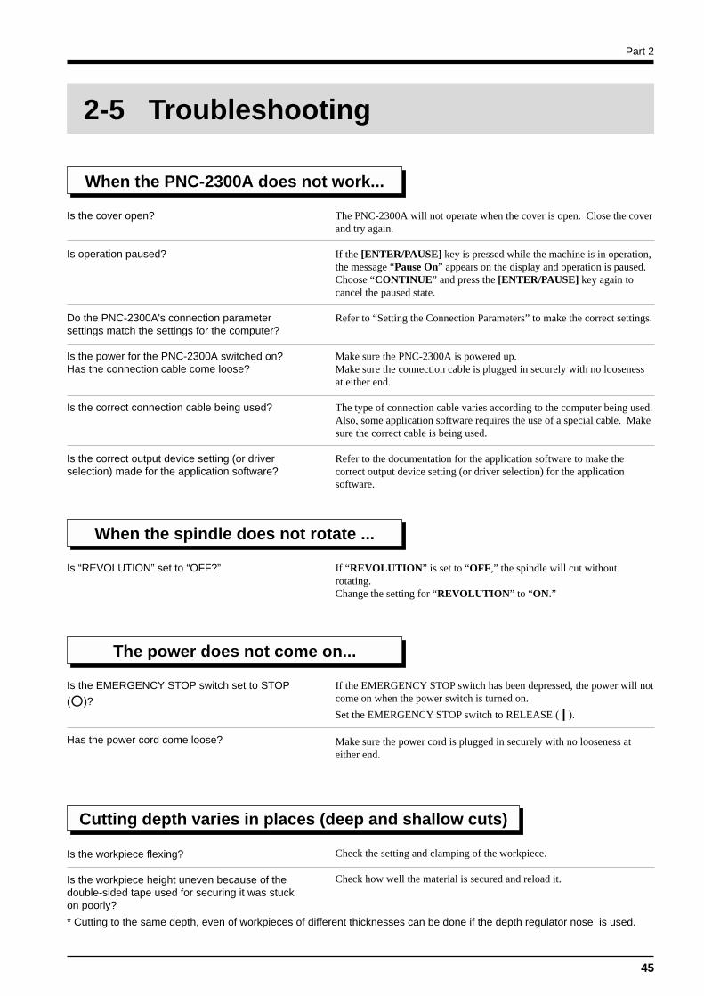
Is the cover open?
Is operation paused?
Do the PNC-2300A's connection parametersettings match the settings for the computer?
Is the power for the PNC-2300A switched on?Has the connection cable come loose?
Is the correct connection cable being used?
Is the correct output device setting (or driverselection) made for the application software?
The PNC-2300A will not operate when the cover is open. Close the coverand try again.
If the [ENTER/PAUSE] key is pressed while the machine is in operation,the message “Pause On” appears on the display and operation is paused.Choose “CONTINUE” and press the [ENTER/PAUSE] key again tocancel the paused state.
Refer to “Setting the Connection Parameters” to make the correct settings.
Make sure the PNC-2300A is powered up.Make sure the connection cable is plugged in securely with no loosenessat either end.
The type of connection cable varies according to the computer being used.Also, some application software requires the use of a special cable. Makesure the correct cable is being used.
Refer to the documentation for the application software to make thecorrect output device setting (or driver selection) for the applicationsoftware.
When the PNC-2300A does not work...
Is “REVOLUTION” set to “OFF?” If “REVOLUTION” is set to “OFF,” the spindle will cut withoutrotating.Change the setting for “REVOLUTION” to “ON.”
When the spindle does not rotate ...
The power does not come on...
Is the EMERGENCY STOP switch set to STOP
( )?
Has the power cord come loose?
If the EMERGENCY STOP switch has been depressed, the power will notcome on when the power switch is turned on.
Set the EMERGENCY STOP switch to RELEASE ( ).
Make sure the power cord is plugged in securely with no looseness ateither end.
Cutting depth varies in places (deep and shallow cuts)
Is the workpiece flexing?
Is the workpiece height uneven because of thedouble-sided tape used for securing it was stuckon poorly?
Check the setting and clamping of the workpiece.
Check how well the material is secured and reload it.
* Cutting to the same depth, even of workpieces of different thicknesses can be done if the depth regulator nose is used.
2-5 Troubleshooting
Part 2
46
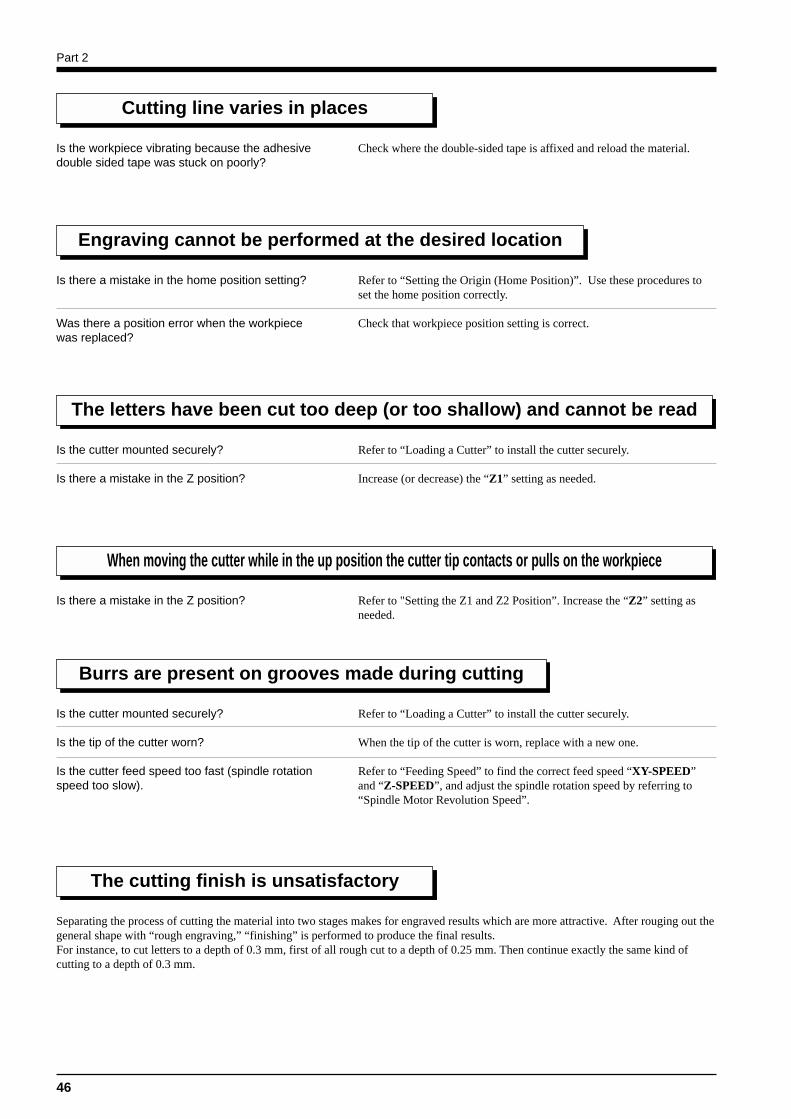
Cutting line varies in places
Is the workpiece vibrating because the adhesivedouble sided tape was stuck on poorly?
Check where the double-sided tape is affixed and reload the material.
Engraving cannot be performed at the desired location
Is there a mistake in the home position setting?
Was there a position error when the workpiecewas replaced?
Refer to “Setting the Origin (Home Position)”. Use these procedures toset the home position correctly.
Check that workpiece position setting is correct.
The letters have been cut too deep (or too shallow) and cannot be read
Is the cutter mounted securely?
Is there a mistake in the Z position?
Refer to “Loading a Cutter” to install the cutter securely.
Increase (or decrease) the “Z1” setting as needed.
When moving the cutter while in the up position the cutter tip contacts or pulls on the workpiece
Is there a mistake in the Z position? Refer to "Setting the Z1 and Z2 Position”. Increase the “Z2” setting asneeded.
Burrs are present on grooves made during cutting
Is the cutter mounted securely?
Is the tip of the cutter worn?
Is the cutter feed speed too fast (spindle rotationspeed too slow).
Refer to “Loading a Cutter” to install the cutter securely.
When the tip of the cutter is worn, replace with a new one.
Refer to “Feeding Speed” to find the correct feed speed “XY-SPEED”and “Z-SPEED”, and adjust the spindle rotation speed by referring to“Spindle Motor Revolution Speed”.
The cutting finish is unsatisfactory
Separating the process of cutting the material into two stages makes for engraved results which are more attractive. After rouging out thegeneral shape with “rough engraving,” “finishing” is performed to produce the final results.For instance, to cut letters to a depth of 0.3 mm, first of all rough cut to a depth of 0.25 mm. Then continue exactly the same kind ofcutting to a depth of 0.3 mm.
Part 2
47
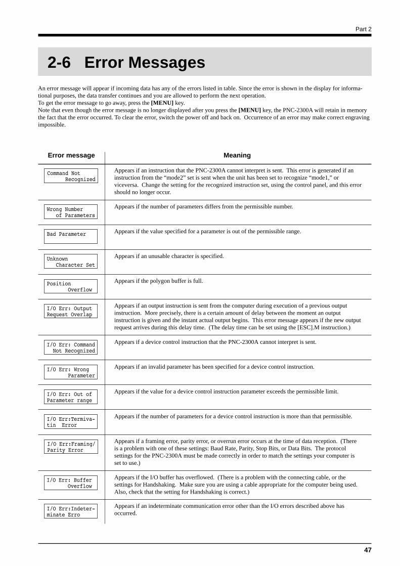
An error message will appear if incoming data has any of the errors listed in table. Since the error is shown in the display for informa-tional purposes, the data transfer continues and you are allowed to perform the next operation.To get the error message to go away, press the [MENU] key.Note that even though the error message is no longer displayed after you press the [MENU] key, the PNC-2300A will retain in memorythe fact that the error occurred. To clear the error, switch the power off and back on. Occurrence of an error may make correct engravingimpossible.
Meaning
Appears if an instruction that the PNC-2300A cannot interpret is sent. This error is generated if aninstruction from the “mode2” set is sent when the unit has been set to recognize “mode1,” orviceversa. Change the setting for the recognized instruction set, using the control panel, and this errorshould no longer occur.
Error message
Appears if the number of parameters differs from the permissible number.
Appears if the value specified for a parameter is out of the permissible range.
Appears if an unusable character is specified.
Appears if an output instruction is sent from the computer during execution of a previous outputinstruction. More precisely, there is a certain amount of delay between the moment an outputinstruction is given and the instant actual output begins. This error message appears if the new outputrequest arrives during this delay time. (The delay time can be set using the [ESC].M instruction.)
Appears if a device control instruction that the PNC-2300A cannot interpret is sent.
Appears if an invalid parameter has been specified for a device control instruction.
Appears if the value for a device control instruction parameter exceeds the permissible limit.
Appears if the number of parameters for a device control instruction is more than that permissible.
Appears if a framing error, parity error, or overrun error occurs at the time of data reception. (Thereis a problem with one of these settings: Baud Rate, Parity, Stop Bits, or Data Bits. The protocolsettings for the PNC-2300A must be made correctly in order to match the settings your computer isset to use.)
Appears if the I/O buffer has overflowed. (There is a problem with the connecting cable, or thesettings for Handshaking. Make sure you are using a cable appropriate for the computer being used.Also, check that the setting for Handshaking is correct.)
Appears if the polygon buffer is full.
Appears if an indeterminate communication error other than the I/O errors described above hasoccurred.
2-6 Error Messages
Part 2
48
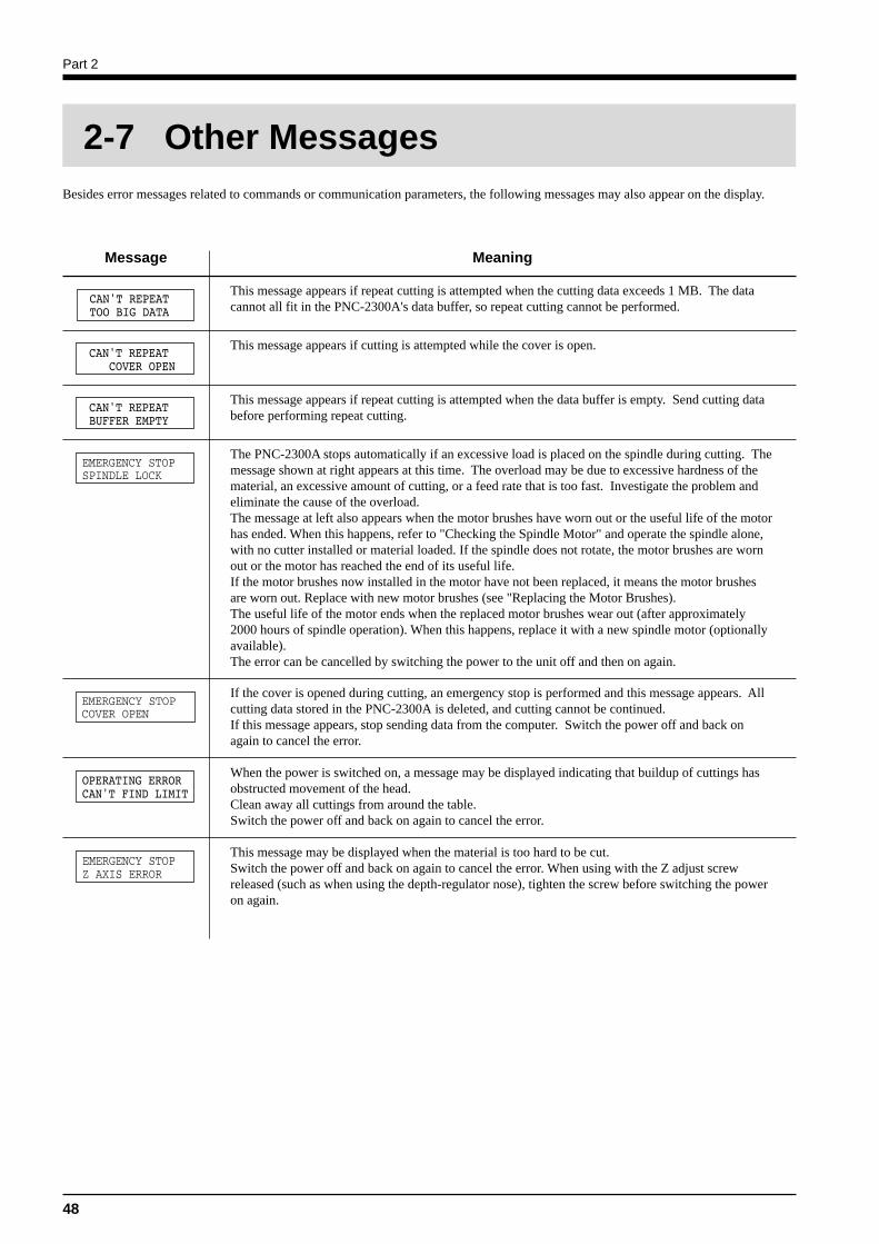
Besides error messages related to commands or communication parameters, the following messages may also appear on the display.
Message Meaning
This message appears if repeat cutting is attempted when the cutting data exceeds 1 MB. The datacannot all fit in the PNC-2300A's data buffer, so repeat cutting cannot be performed.
This message appears if cutting is attempted while the cover is open.
This message appears if repeat cutting is attempted when the data buffer is empty. Send cutting databefore performing repeat cutting.
The PNC-2300A stops automatically if an excessive load is placed on the spindle during cutting. Themessage shown at right appears at this time. The overload may be due to excessive hardness of thematerial, an excessive amount of cutting, or a feed rate that is too fast. Investigate the problem andeliminate the cause of the overload.The message at left also appears when the motor brushes have worn out or the useful life of the motorhas ended. When this happens, refer to "Checking the Spindle Motor" and operate the spindle alone,with no cutter installed or material loaded. If the spindle does not rotate, the motor brushes are wornout or the motor has reached the end of its useful life.If the motor brushes now installed in the motor have not been replaced, it means the motor brushesare worn out. Replace with new motor brushes (see "Replacing the Motor Brushes).The useful life of the motor ends when the replaced motor brushes wear out (after approximately2000 hours of spindle operation). When this happens, replace it with a new spindle motor (optionallyavailable).The error can be cancelled by switching the power to the unit off and then on again.
If the cover is opened during cutting, an emergency stop is performed and this message appears. Allcutting data stored in the PNC-2300A is deleted, and cutting cannot be continued.If this message appears, stop sending data from the computer. Switch the power off and back onagain to cancel the error.
When the power is switched on, a message may be displayed indicating that buildup of cuttings hasobstructed movement of the head.Clean away all cuttings from around the table.Switch the power off and back on again to cancel the error.
2-7 Other Messages
This message may be displayed when the material is too hard to be cut.Switch the power off and back on again to cancel the error. When using with the Z adjust screwreleased (such as when using the depth-regulator nose), tighten the screw before switching the poweron again.
Part 2
49
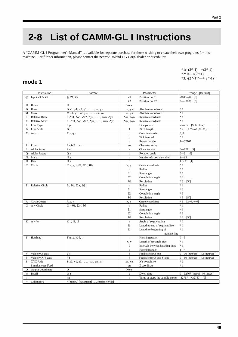
A “CAMM-GL I Programmer's Manual” is available for separate purchase for those wishing to create their own programs for thismachine. For further information, please contact the nearest Roland DG Corp. dealer or distributor.
*1: -(226-1)—+(226-1)*2: 0—+(226-1)*3: -(226-1)°—+(226-1)°
mode 1
2-8 List of CAMM-GL I Instructions
Instruction Format Parameter Range [Default]@ Input Z1 & Z2 @ Z1, Z2 Z1 Position on Z1 -3000—0 [0]
Z2 Position on Z2 0—+3000 [0]
H Home H None
D Draw D x1, y1, x2, y2, ...... , xn, yn xn, yn Absolute coordinate * 1M Move M x1, y1, x2, y2, ...... , xn, yn xn, yn Absolute coordinate * 1
I Relative Draw I ∆x1, ∆y1, ∆x2, ∆y2, ...... , ∆xn, ∆yn ∆xn, ∆yn Relative coordinate * 1
R Relative Move R ∆x1, ∆y1, ∆x2, ∆y2, ...... , ∆xn, ∆yn ∆xn, ∆yn Relative coordinate * 1
L Line Type L p p Line pattern -5—+5 [Solid line]
B Line Scale B l l Pitch length * 2 [1.5% of (P2-P1)]
X Axis X p, q, r p Coordinate axis 0, 1
q Tick interval * 1
r Repeat number 1—32767
P Print P c1c2......cn cn Character string
S Alpha Scale S n n Character size 0—127 [3]
Q Alpha Rotate Q n n Rotation angle 0—3 [0]
N Mark N n n Number of special symbol 1—15U User U n n 1 or 2 [1]
C Circle C x, y, r, θ1, θ2 (, θd) x, y Center coordinate * 1
r Radius * 1
θ1 Start angle * 3
θ2 Completion angle * 3
θd Resolution * 3 [5°]
E Relative Circle Er, θ1, θ2 (, θd) r Radius * 1
θ1 Start angle * 3
θ2 Completion angle * 3
θd Resolution * 3 [5°]
A Circle Center A x, y x, y Center coordinate * 1 [x=0, y=0]
G A + Circle G r, θ1, θ2 (, θd) r Radius * 1
θ1 Start angle * 3θ2 Completion angle * 3
θd Resolution * 3 [5°]
K A + % K n, l1, l2 n Angle of segment line * 1
l1 Length to end of segment line * 1
l2 Length to beginning of * 1
segment line
T Hatching T n, x, y, d, t n Hatching pattern 0—3
x, y Length of rectangle side * 1
d Intervals between hatching lines * 1
t Hatching angle 1—4
V Velocity Z-axis V f f Feed rate for Z axis 0—30 [mm/sec] [2 [mm/sec]]
F Velocity X,Y-axis F f f Feed rate for X and Y axis 0—60 [mm/sec] [2 [mm/sec]]Z XYZ Axis Z x1, y1, z1, ..... , xn, yn, zn xn, yn XY coordinate * 1
Simultaneous Feed zn Z coordinate * 1
O Output Coordinate O None
W Dwell W t t Dwell time 0—32767 [msec] [0 [msec]]
! ! n n Turns or stops the spindle motor -32767—+32767 [0]
^ Call mode2 ^ [mode2] [parameter] ...... [parameter] [;]
Part 2
50
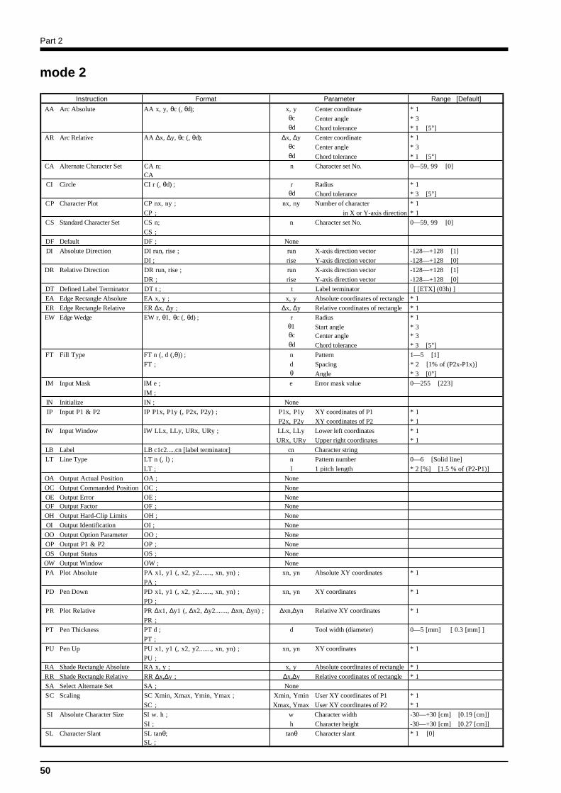
mode 2
Instruction Format Parameter Range [Default]
AA Arc Absolute AA x, y, θc (, θd); x, y Center coordinate * 1θc Center angle * 3θd Chord tolerance * 1 [5°]
AR Arc Relative AA ∆x, ∆y, θc (, θd); ∆x, ∆y Center coordinate * 1 θc Center angle * 3θd Chord tolerance * 1 [5°]
CA Alternate Character Set CA n; n Character set No. 0—59, 99 [0]CA
CI Circle CI r (, θd) ; r Radius * 1θd Chord tolerance * 3 [5°]
CP Character Plot CP nx, ny ; nx, ny Number of character * 1
CP ; in X or Y-axis direction * 1
CS Standard Character Set CS n; n Character set No. 0—59, 99 [0]
CS ;
DF Default DF ; None
DI Absolute Direction DI run, rise ; run X-axis direction vector -128—+128 [1]
DI ; rise Y-axis direction vector -128—+128 [0]
DR Relative Direction DR run, rise ; run X-axis direction vector -128—+128 [1]
DR ; rise Y-axis direction vector -128—+128 [0]
DT Defined Label Terminator DT t ; t Label terminator [ [ETX] (03h) ]
EA Edge Rectangle Absolute EA x, y ; x, y Absolute coordinates of rectangle * 1
ER Edge Rectangle Relative ER ∆x, ∆y ; ∆x, ∆y Relative coordinates of rectangle * 1
EW Edge Wedge EW r, θ1, θc (, θd) ; r Radius * 1θ1 Start angle * 3θc Center angle * 3θd Chord tolerance * 3 [5°]
FT Fill Type FT n (, d (,θ)) ; n Pattern 1—5 [1]
FT ; d Spacing * 2 [1% of (P2x-P1x)]θ Angle * 3 [0°]
IM Input Mask IM e ; e Error mask value 0—255 [223]
IM ;
IN Initialize IN ; None
IP Input P1 & P2 IP P1x, P1y (, P2x, P2y) ; P1x, P1y XY coordinates of P1 * 1
P2x, P2y XY coordinates of P2 * 1
IW Input Window IW LLx, LLy, URx, URy ; LLx, LLy Lower left coordinates * 1
URx, URy Upper right coordinates * 1
LB Label LB c1c2.....cn [label terminator] cn Character string
LT Line Type LT n (, l) ; n Pattern number 0—6 [Solid line]
LT ; l 1 pitch length * 2 [%] [1.5 % of (P2-P1)]
OA Output Actual Position OA ; None
OC Output Commanded Position OC ; None
OE Output Error OE ; NoneOF Output Factor OF ; None
OH Output Hard-Clip Limits OH ; None
OI Output Identification OI ; None
OO Output Option Parameter OO ; None
OP Output P1 & P2 OP ; None
OS Output Status OS ; None
OW Output Window OW ; None
PA Plot Absolute PA x1, y1 (, x2, y2......., xn, yn) ; xn, yn Absolute XY coordinates * 1
PA ;
PD Pen Down PD x1, y1 (, x2, y2......., xn, yn) ; xn, yn XY coordinates * 1
PD ;
PR Plot Relative PR ∆x1, ∆y1 (, ∆x2, ∆y2......., ∆xn, ∆yn) ; ∆xn,∆yn Relative XY coordinates * 1
PR ;
PT Pen Thickness PT d ; d Tool width (diameter) 0—5 [mm] [ 0.3 [mm] ]
PT ;
PU Pen Up PU x1, y1 (, x2, y2......., xn, yn) ; xn, yn XY coordinates * 1
PU ;RA Shade Rectangle Absolute RA x, y ; x, y Absolute coordinates of rectangle * 1
RR Shade Rectangle Relative RR ∆x,∆y ; ∆x,∆y Relative coordinates of rectangle * 1
SA Select Alternate Set SA ; None
SC Scaling SC Xmin, Xmax, Ymin, Ymax ; Xmin, Ymin User XY coordinates of P1 * 1
SC ; Xmax, Ymax User XY coordinates of P2 * 1
SI Absolute Character Size SI w. h ; w Character width -30—+30 [cm] [0.19 [cm]]
SI ; h Character height -30—+30 [cm] [0.27 [cm]]
SL Character Slant SL tanθ; tanθ Character slant * 1 [0]SL ;
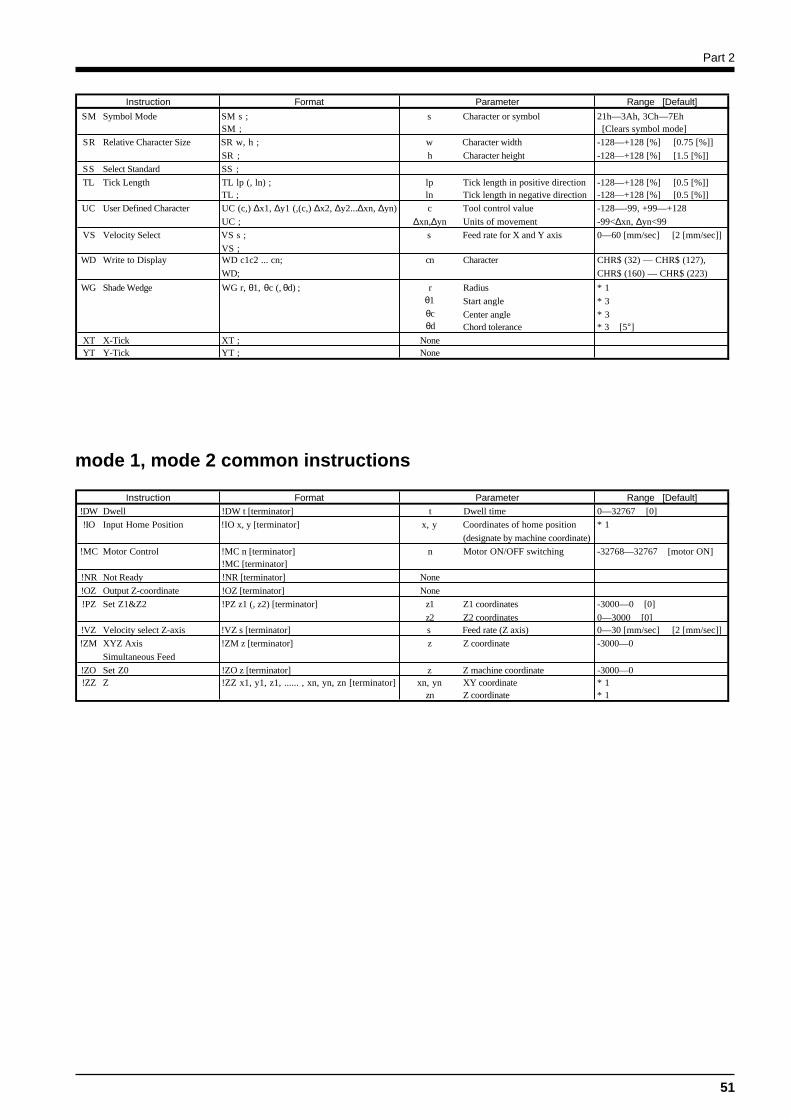
Part 2
51
mode 1, mode 2 common instructions
Instruction Format Parameter Range [Default]
SM Symbol Mode SM s ; s Character or symbol 21h—3Ah, 3Ch—7EhSM ; [Clears symbol mode]
SR Relative Character Size SR w, h ; w Character width -128—+128 [%] [0.75 [%]]
SR ; h Character height -128—+128 [%] [1.5 [%]]
SS Select Standard SS ;
TL Tick Length TL lp (, ln) ; lp Tick length in positive direction -128—+128 [%] [0.5 [%]]TL ; ln Tick length in negative direction -128—+128 [%] [0.5 [%]]
UC User Defined Character UC (c,) ∆x1, ∆y1 (,(c,) ∆x2, ∆y2...∆xn, ∆yn) c Tool control value -128—-99, +99—+128
UC ; ∆xn,∆yn Units of movement -99<∆xn, ∆yn<99
VS Velocity Select VS s ; s Feed rate for X and Y axis 0—60 [mm/sec] [2 [mm/sec]]
VS ;WD Write to Display WD c1c2 ... cn; cn Character CHR$ (32) — CHR$ (127),
WD; CHR$ (160) — CHR$ (223)
WG Shade Wedge WG r, θ1, θc (, θd) ; r Radius * 1θ1 Start angle * 3θc Center angle * 3θd Chord tolerance * 3 [5°]
XT X-Tick XT ; NoneYT Y-Tick YT ; None
Instruction Format Parameter Range [Default]!DW Dwell !DW t [terminator] t Dwell time 0—32767 [0]
!IO Input Home Position !IO x, y [terminator] x, y Coordinates of home position * 1
(designate by machine coordinate)
!MC Motor Control !MC n [terminator] n Motor ON/OFF switching -32768—32767 [motor ON]!MC [terminator]
!NR Not Ready !NR [terminator] None
!OZ Output Z-coordinate !OZ [terminator] None
!PZ Set Z1&Z2 !PZ z1 (, z2) [terminator] z1 Z1 coordinates -3000—0 [0]
z2 Z2 coordinates 0—3000 [0]!VZ Velocity select Z-axis !VZ s [terminator] s Feed rate (Z axis) 0—30 [mm/sec] [2 [mm/sec]]
!ZM XYZ Axis !ZM z [terminator] z Z coordinate -3000—0
Simultaneous Feed
!ZO Set Z0 !ZO z [terminator] z Z machine coordinate -3000—0!ZZ Z !ZZ x1, y1, z1, ...... , xn, yn, zn [terminator] xn, yn XY coordinate * 1
zn Z coordinate * 1
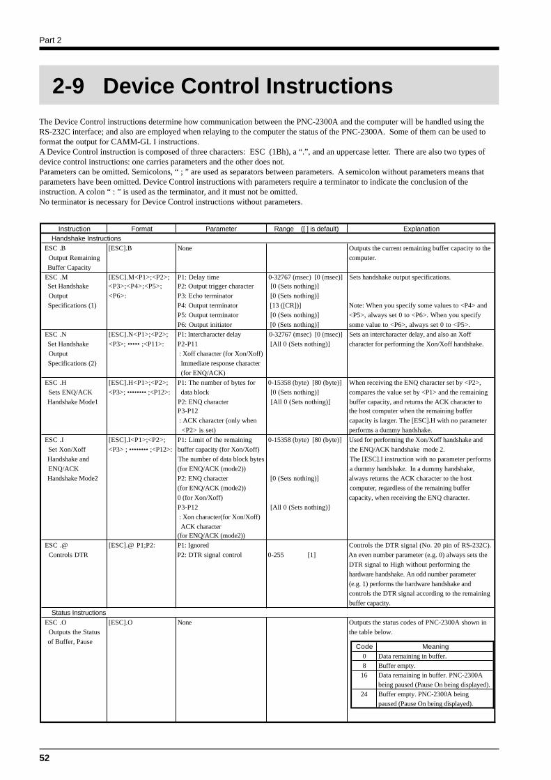
Part 2
52
The Device Control instructions determine how communication between the PNC-2300A and the computer will be handled using theRS-232C interface; and also are employed when relaying to the computer the status of the PNC-2300A. Some of them can be used toformat the output for CAMM-GL I instructions.A Device Control instruction is composed of three characters: ESC (1Bh), a “.”, and an uppercase letter. There are also two types ofdevice control instructions: one carries parameters and the other does not.Parameters can be omitted. Semicolons, “ ; ” are used as separators between parameters. A semicolon without parameters means thatparameters have been omitted. Device Control instructions with parameters require a terminator to indicate the conclusion of theinstruction. A colon “ : ” is used as the terminator, and it must not be omitted.No terminator is necessary for Device Control instructions without parameters.
2-9 Device Control Instructions
Code Meaning0 Data remaining in buffer.
8 Buffer empty.
16 Data remaining in buffer. PNC-2300A
being paused (Pause On being displayed).
24 Buffer empty. PNC-2300A being
paused (Pause On being displayed).
Instruction Format Parameter Range ([ ] is default) Explanation Handshake Instructions ESC .B [ESC].B None Outputs the current remaining buffer capacity to the
Output Remaining computer.
Buffer Capacity
ESC .M [ESC].M<P1>;<P2>; P1: Delay time 0-32767 (msec) [0 (msec)] Sets handshake output specifications. Set Handshake <P3>;<P4>;<P5>; P2: Output trigger character [0 (Sets nothing)]
Output <P6>: P3: Echo terminator [0 (Sets nothing)]
Specifications (1) P4: Output terminator [13 ([CR])] Note: When you specify some values to <P4> and
P5: Output terminator [0 (Sets nothing)] <P5>, always set 0 to <P6>. When you specify
P6: Output initiator [0 (Sets nothing)] some value to <P6>, always set 0 to <P5>.
ESC .N [ESC].N<P1>;<P2>; P1: Intercharacter delay 0-32767 (msec) [0 (msec)] Sets an intercharacter delay, and also an Xoff
Set Handshake <P3>; ••••• ;<P11>: P2-P11 [All 0 (Sets nothing)] character for performing the Xon/Xoff handshake.
Output : Xoff character (for Xon/Xoff)
Specifications (2) Immediate response character
(for ENQ/ACK)
ESC .H [ESC].H<P1>;<P2>; P1: The number of bytes for 0-15358 (byte) [80 (byte)] When receiving the ENQ character set by <P2>,
Sets ENQ/ACK <P3>; •••••••• ;<P12>: data block [0 (Sets nothing)] compares the value set by <P1> and the remaining
Handshake Mode1 P2: ENQ character [All 0 (Sets nothing)] buffer capacity, and returns the ACK character to P3-P12 the host computer when the remaining buffer
: ACK character (only when capacity is larger. The [ESC].H with no parameter
<P2> is set) performs a dummy handshake.
ESC .I [ESC].I<P1>;<P2>; P1: Limit of the remaining 0-15358 (byte) [80 (byte)] Used for performing the Xon/Xoff handshake and
Set Xon/Xoff <P3> ; •••••••• ;<P12>: buffer capacity (for Xon/Xoff) the ENQ/ACK handshake mode 2.
Handshake and The number of data block bytes The [ESC].I instruction with no parameter performs
ENQ/ACK (for ENQ/ACK (mode2)) a dummy handshake. In a dummy handshake,
Handshake Mode2 P2: ENQ character [0 (Sets nothing)] always returns the ACK character to the host
(for ENQ/ACK (mode2)) computer, regardless of the remaining buffer
0 (for Xon/Xoff) capacity, when receiving the ENQ character.
P3-P12 [All 0 (Sets nothing)]
: Xon character(for Xon/Xoff)
ACK character(for ENQ/ACK (mode2))
ESC .@ [ESC].@ P1;P2: P1: Ignored Controls the DTR signal (No. 20 pin of RS-232C).
Controls DTR P2: DTR signal control 0-255 [1] An even number parameter (e.g. 0) always sets the
DTR signal to High without performing the
hardware handshake. An odd number parameter
(e.g. 1) performs the hardware handshake and
controls the DTR signal according to the remaining
buffer capacity.
Status Instructions ESC .O [ESC].O None Outputs the status codes of PNC-2300A shown in
Outputs the Status the table below.
of Buffer, Pause
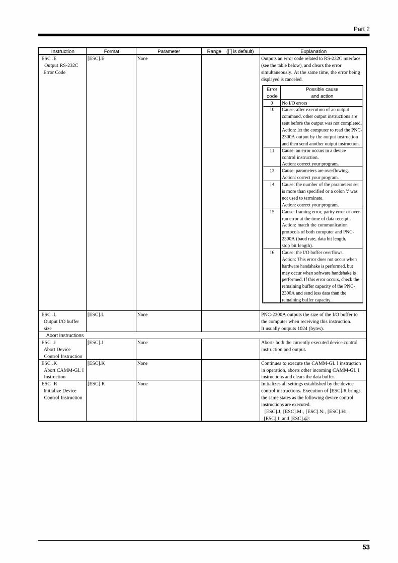
Part 2
53
Instruction Format Parameter Range ([ ] is default) Explanation ESC .E [ESC].E None Outputs an error code related to RS-232C interface
Output RS-232C (see the table below), and clears the error
Error Code simultaneously. At the same time, the error being
displayed is canceled.
ESC .L [ESC].L None PNC-2300A outputs the size of the I/O buffer to
Output I/O buffer the computer when receiving this instruction.
size It usually outputs 1024 (bytes).
Abort Instructions ESC .J [ESC].J None Aborts both the currently executed device control
Abort Device instruction and output.
Control Instruction
ESC .K [ESC].K None Continues to execute the CAMM-GL I instruction
Abort CAMM-GL I in operation, aborts other incoming CAMM-GL I Instruction instructions and clears the data buffer.
ESC .R [ESC].R None Initializes all settings established by the device
Initialize Device control instructions. Execution of [ESC].R brings
Control Instruction the same states as the following device control
instructions are executed.
[ESC].J, [ESC].M:, [ESC].N:, [ESC].H:,
[ESC].I: and [ESC].@:
Error Possible causecode and action
0 No I/O errors10 Cause: after execution of an output
command, other output instructions are
sent before the output was not completed.
Action: let the computer to read the PNC-
2300A output by the output instruction
and then send another output instruction.
11 Cause: an error occurs in a device
control instruction.Action: correct your program.
13 Cause: parameters are overflowing.
Action: correct your program.
14 Cause: the number of the parameters set
is more than specified or a colon ':' was
not used to terminate.
Action: correct your program.
15 Cause: framing error, parity error or over-
run error at the time of data receipt .Action: match the communication
protocols of both computer and PNC-
2300A (baud rate, data bit length,
stop bit length).
16 Cause: the I/O buffer overflows.
Action: This error does not occur when
hardware handshake is performed, but
may occur when software handshake is performed. If this error occurs, check the
remaining buffer capacity of the PNC-
2300A and send less data than the
remaining buffer capacity.
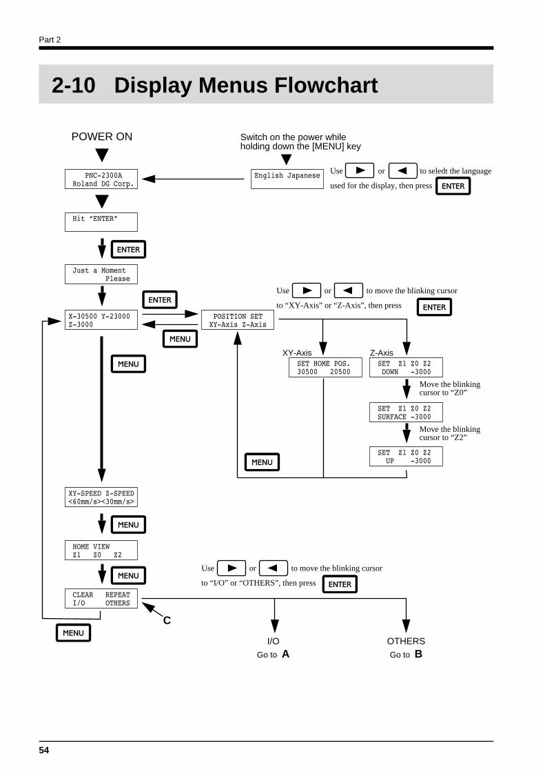
Part 2
54
2-10 Display Menus Flowchart
POWER ON Switch on the power while holding down the [MENU] key
Use or to move the blinking cursor
to “XY-Axis” or “Z-Axis”, then press
XY-Axis Z-Axis
I/O
Go to AOTHERS
Go to B
C
Use or to seledt the language
used for the display, then press
Use or to move the blinking cursor
to “I/O” or “OTHERS”, then press
Move the blinking cursor to “Z0”
Move the blinking cursor to “Z2”

Part 2
55
Menu Flowchart When Paused
I/O OTHERS
Go to CA B
For “I/O”, select “PARALLEL” then press
For “I/O”, select “SERIAL” or “AUTO” then press
COVER OPENED
COVER CLOSED
Press the [ENTER/PAUSE] key while cutting is in progress
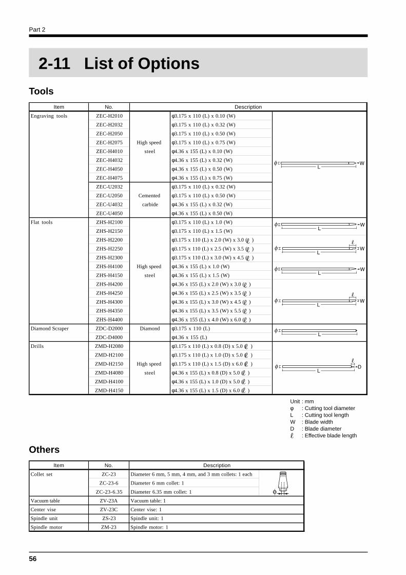
Part 2
56
Others
2-11 List of Options
Tools
Unit : mmφ : Cutting tool diameterL : Cutting tool lengthW : Blade widthD : Blade diameter
: Effective blade length
Item No. Description
Engraving tools ZEC-H2010 φ3.175 x 110 (L) x 0.10 (W)
ZEC-H2032 φ3.175 x 110 (L) x 0.32 (W)
ZEC-H2050 φ3.175 x 110 (L) x 0.50 (W)
ZEC-H2075 High speed φ3.175 x 110 (L) x 0.75 (W)
ZEC-H4010 steel φ4.36 x 155 (L) x 0.10 (W)
ZEC-H4032 φ4.36 x 155 (L) x 0.32 (W)
ZEC-H4050 φ4.36 x 155 (L) x 0.50 (W)
ZEC-H4075 φ4.36 x 155 (L) x 0.75 (W)
ZEC-U2032 φ3.175 x 110 (L) x 0.32 (W)
ZEC-U2050 Cemented φ3.175 x 110 (L) x 0.50 (W)
ZEC-U4032 carbide φ4.36 x 155 (L) x 0.32 (W)
ZEC-U4050 φ4.36 x 155 (L) x 0.50 (W)
Flat tools ZHS-H2100 φ3.175 x 110 (L) x 1.0 (W)
ZHS-H2150 φ3.175 x 110 (L) x 1.5 (W)
ZHS-H2200 φ3.175 x 110 (L) x 2.0 (W) x 3.0 ( )
ZHS-H2250 φ3.175 x 110 (L) x 2.5 (W) x 3.5 ( )
ZHS-H2300 φ3.175 x 110 (L) x 3.0 (W) x 4.5 ( )
ZHS-H4100 High speed φ4.36 x 155 (L) x 1.0 (W)
ZHS-H4150 steel φ4.36 x 155 (L) x 1.5 (W)
ZHS-H4200 φ4.36 x 155 (L) x 2.0 (W) x 3.0 ( )
ZHS-H4250 φ4.36 x 155 (L) x 2.5 (W) x 3.5 ( )
ZHS-H4300 φ4.36 x 155 (L) x 3.0 (W) x 4.5 ( )
ZHS-H4350 φ4.36 x 155 (L) x 3.5 (W) x 5.5 ( )
ZHS-H4400 φ4.36 x 155 (L) x 4.0 (W) x 6.0 ( )
Diamond Scraper ZDC-D2000 Diamond φ3.175 x 110 (L)
ZDC-D4000 φ4.36 x 155 (L)
Drills ZMD-H2080 φ3.175 x 110 (L) x 0.8 (D) x 5.0 ( )
ZMD-H2100 φ3.175 x 110 (L) x 1.0 (D) x 5.0 ( )
ZMD-H2150 High speed φ3.175 x 110 (L) x 1.5 (D) x 6.0 ( )
ZMD-H4080 steel φ4.36 x 155 (L) x 0.8 (D) x 5.0 ( )
ZMD-H4100 φ4.36 x 155 (L) x 1.0 (D) x 5.0 ( )
ZMD-H4150 φ4.36 x 155 (L) x 1.5 (D) x 6.0 ( )
Item No. Description
Collet set ZC-23 Diameter 6 mm, 5 mm, 4 mm, and 3 mm collets: 1 each
ZC-23-6 Diameter 6 mm collet: 1
ZC-23-6.35 Diameter 6.35 mm collet: 1
Vacuum table ZV-23A Vacuum table: 1
Center vise ZV-23C Center vise: 1
Spindle unit ZS-23 Spindle unit: 1
Spindle motor ZM-23 Spindle motor: 1
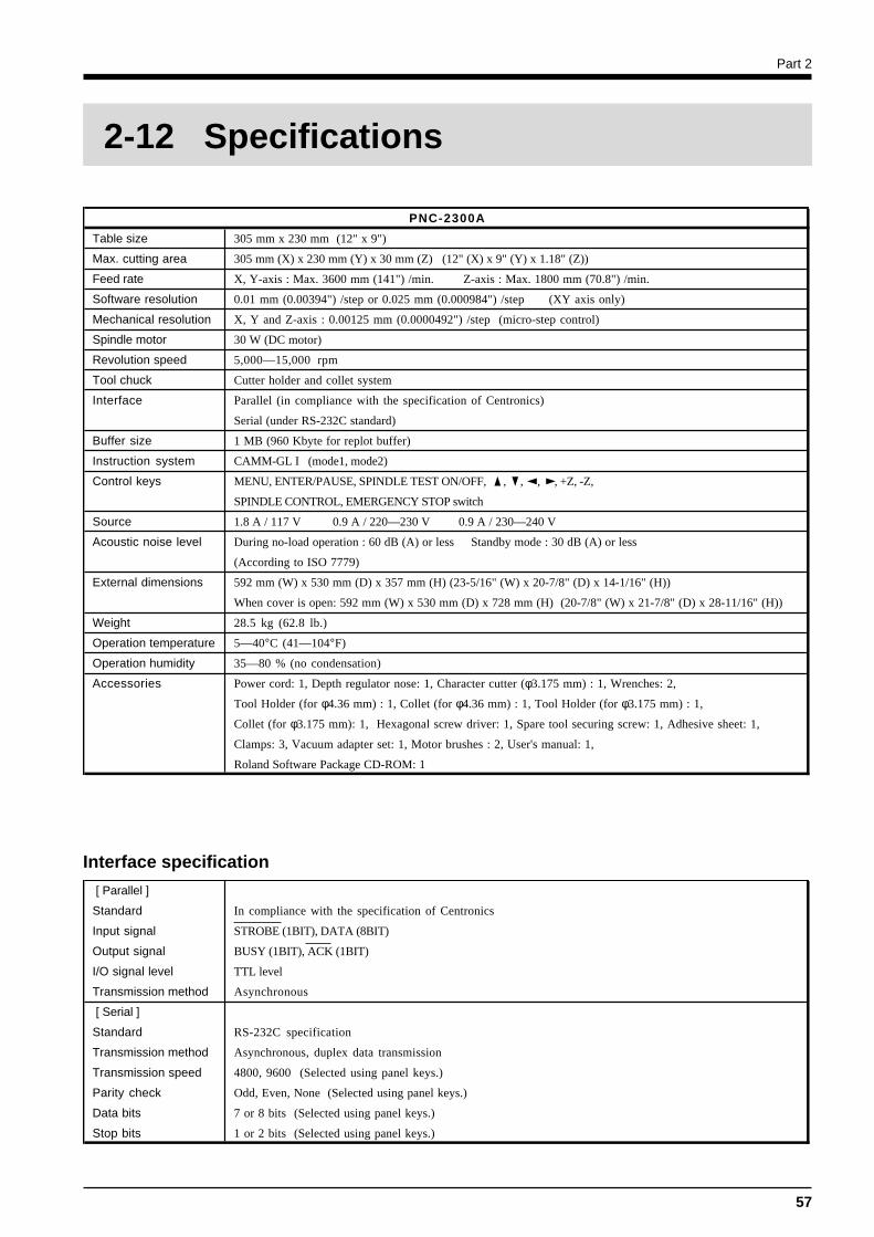
Part 2
57
Interface specification
2-12 Specifications
PNC-2300A
Table size 305 mm x 230 mm (12" x 9")
Max. cutting area 305 mm (X) x 230 mm (Y) x 30 mm (Z) (12" (X) x 9" (Y) x 1.18" (Z))
Feed rate X, Y-axis : Max. 3600 mm (141") /min. Z-axis : Max. 1800 mm (70.8") /min.
Software resolution 0.01 mm (0.00394") /step or 0.025 mm (0.000984") /step (XY axis only)
Mechanical resolution X, Y and Z-axis : 0.00125 mm (0.0000492") /step (micro-step control)
Spindle motor 30 W (DC motor)
Revolution speed 5,000—15,000 rpm
Tool chuck Cutter holder and collet system
Interface Parallel (in compliance with the specification of Centronics)
Serial (under RS-232C standard)
Buffer size 1 MB (960 Kbyte for replot buffer)
Instruction system CAMM-GL I (mode1, mode2)
Control keys MENU, ENTER/PAUSE, SPINDLE TEST ON/OFF, , , , , +Z, -Z,
SPINDLE CONTROL, EMERGENCY STOP switch
Source 1.8 A / 117 V 0.9 A / 220—230 V 0.9 A / 230—240 V
Acoustic noise level During no-load operation : 60 dB (A) or less Standby mode : 30 dB (A) or less
(According to ISO 7779)
External dimensions 592 mm (W) x 530 mm (D) x 357 mm (H) (23-5/16" (W) x 20-7/8" (D) x 14-1/16" (H))
When cover is open: 592 mm (W) x 530 mm (D) x 728 mm (H) (20-7/8" (W) x 21-7/8" (D) x 28-11/16" (H))
Weight 28.5 kg (62.8 lb.)
Operation temperature 5—40°C (41—104°F)
Operation humidity 35—80 % (no condensation)
Accessories Power cord: 1, Depth regulator nose: 1, Character cutter (φ3.175 mm) : 1, Wrenches: 2,
Tool Holder (for φ4.36 mm) : 1, Collet (for φ4.36 mm) : 1, Tool Holder (for φ3.175 mm) : 1,
Collet (for φ3.175 mm): 1, Hexagonal screw driver: 1, Spare tool securing screw: 1, Adhesive sheet: 1,
Clamps: 3, Vacuum adapter set: 1, Motor brushes : 2, User's manual: 1,
Roland Software Package CD-ROM: 1
[ Parallel ]
Standard In compliance with the specification of Centronics
Input signal STROBE (1BIT), DATA (8BIT)
Output signal BUSY (1BIT), ACK (1BIT)
I/O signal level TTL level
Transmission method Asynchronous
[ Serial ]
Standard RS-232C specification
Transmission method Asynchronous, duplex data transmission
Transmission speed 4800, 9600 (Selected using panel keys.)
Parity check Odd, Even, None (Selected using panel keys.)
Data bits 7 or 8 bits (Selected using panel keys.)
Stop bits 1 or 2 bits (Selected using panel keys.)
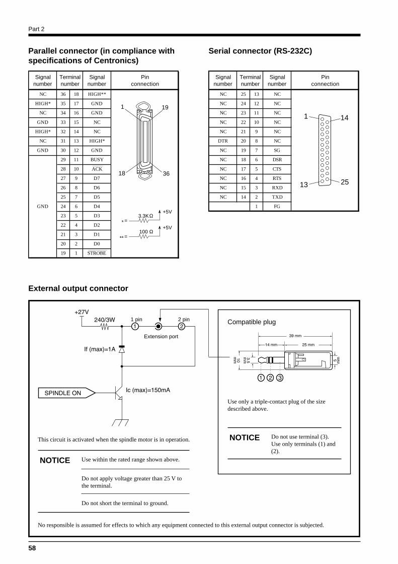
Part 2
58
Parallel connector (in compliance withspecifications of Centronics)
Serial connector (RS-232C)
1 19
18 36
3.3K+5V
=*Ω
100+5V
=**Ω
1 14
13 25
External output connector
This circuit is activated when the spindle motor is in operation.
Extension port
1 pin 2 pin Compatible plug
No responsible is assumed for effects to which any equipment connected to this external output connector is subjected.
Use only a triple-contact plug of the sizedescribed above.
Do not use terminal (3).Use only terminals (1) and(2).
NOTICE
Use within the rated range shown above.NOTICE
Do not apply voltage greater than 25 V tothe terminal.
Do not short the terminal to ground.
Signal Terminal Signal Pinnumber number number connection
NC 36 18 HIGH**
HIGH* 35 17 GND
NC 34 16 GND
GND 33 15 NC
HIGH* 32 14 NC
NC 31 13 HIGH*
GND 30 12 GND
29 11 BUSY
28 10 ACK
27 9 D7
26 8 D6
25 7 D5
GND 24 6 D4
23 5 D3
22 4 D2
21 3 D1
20 2 D0
19 1 STROBE
Signal Terminal Signal Pinnumber number number connection
NC 25 13 NC
NC 24 12 NC
NC 23 11 NC
NC 22 10 NC
NC 21 9 NC
DTR 20 8 NC
NC 19 7 SG
NC 18 6 DSR
NC 17 5 CTS
NC 16 4 RTS
NC 15 3 RXD
NC 14 2 TXD
1 FG
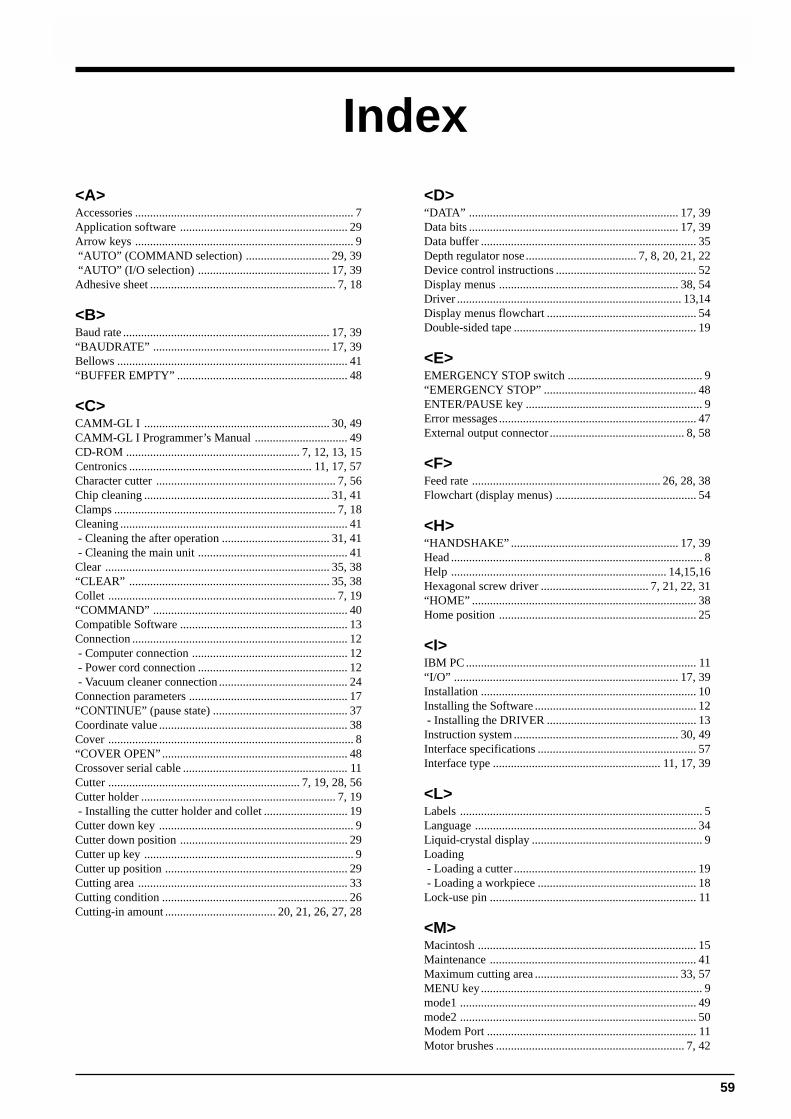
Part 2
59
<A>Accessories ......................................................................... 7Application software ........................................................ 29Arrow keys ......................................................................... 9 “AUTO” (COMMAND selection) ............................ 29, 39 “AUTO” (I/O selection) ............................................ 17, 39Adhesive sheet .............................................................. 7, 18
<B>Baud rate ..................................................................... 17, 39“BAUDRATE” ........................................................... 17, 39Bellows ............................................................................. 41“BUFFER EMPTY” ......................................................... 48
<C>CAMM-GL I .............................................................. 30, 49CAMM-GL I Programmer’s Manual ............................... 49CD-ROM .......................................................... 7, 12, 13, 15Centronics ............................................................. 11, 17, 57Character cutter ............................................................ 7, 56Chip cleaning .............................................................. 31, 41Clamps .......................................................................... 7, 18Cleaning ............................................................................ 41 - Cleaning the after operation .................................... 31, 41 - Cleaning the main unit .................................................. 41Clear ........................................................................... 35, 38“CLEAR” ................................................................... 35, 38Collet ............................................................................ 7, 19“COMMAND” ................................................................. 40Compatible Software ........................................................ 13Connection ........................................................................ 12 - Computer connection .................................................... 12 - Power cord connection .................................................. 12 - Vacuum cleaner connection ........................................... 24Connection parameters ..................................................... 17“CONTINUE” (pause state) ............................................. 37Coordinate value ............................................................... 38Cover .................................................................................. 8“COVER OPEN” .............................................................. 48Crossover serial cable ....................................................... 11Cutter ................................................................ 7, 19, 28, 56Cutter holder ................................................................. 7, 19 - Installing the cutter holder and collet ............................ 19Cutter down key ................................................................. 9Cutter down position ........................................................ 29Cutter up key ...................................................................... 9Cutter up position ............................................................. 29Cutting area ...................................................................... 33Cutting condition .............................................................. 26Cutting-in amount ..................................... 20, 21, 26, 27, 28
Index<D>“DATA” ...................................................................... 17, 39Data bits ...................................................................... 17, 39Data buffer ........................................................................ 35Depth regulator nose ..................................... 7, 8, 20, 21, 22Device control instructions ............................................... 52Display menus ............................................................ 38, 54Driver ........................................................................... 13,14Display menus flowchart .................................................. 54Double-sided tape ............................................................. 19
<E>EMERGENCY STOP switch ............................................. 9“EMERGENCY STOP” ................................................... 48ENTER/PAUSE key ........................................................... 9Error messages .................................................................. 47External output connector ............................................. 8, 58
<F>Feed rate ............................................................... 26, 28, 38Flowchart (display menus) ............................................... 54
<H>“HANDSHAKE” ........................................................ 17, 39Head .................................................................................... 8Help ........................................................................ 14,15,16Hexagonal screw driver .................................... 7, 21, 22, 31“HOME” ........................................................................... 38Home position .................................................................. 25
<I>IBM PC ............................................................................. 11“I/O” ........................................................................... 17, 39Installation ........................................................................ 10Installing the Software ...................................................... 12 - Installing the DRIVER .................................................. 13Instruction system ....................................................... 30, 49Interface specifications ..................................................... 57Interface type ........................................................ 11, 17, 39
<L>Labels ................................................................................. 5Language .......................................................................... 34Liquid-crystal display ......................................................... 9Loading - Loading a cutter ............................................................. 19 - Loading a workpiece ..................................................... 18Lock-use pin ..................................................................... 11
<M>Macintosh ......................................................................... 15Maintenance ..................................................................... 41Maximum cutting area ................................................ 33, 57MENU key.......................................................................... 9mode1 ............................................................................... 49mode2 ............................................................................... 50Modem Port ...................................................................... 11Motor brushes ............................................................... 7, 42
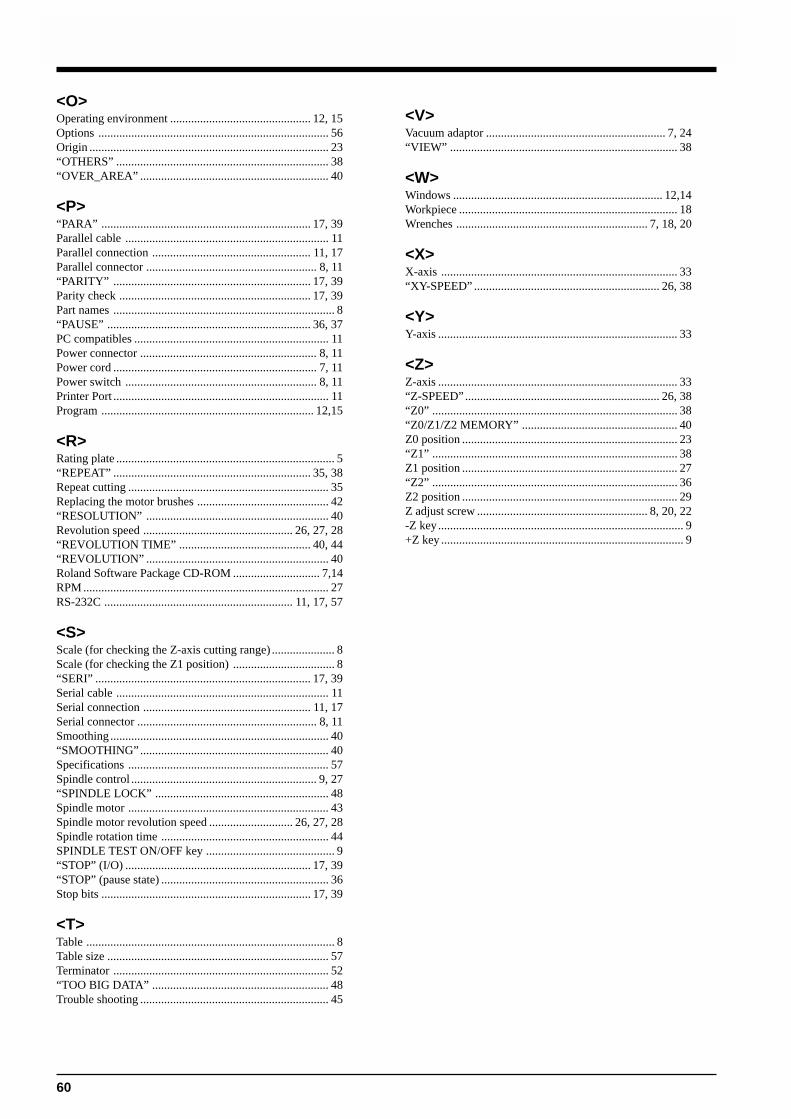
Part 2
60
<O>Operating environment ............................................... 12, 15Options ............................................................................. 56Origin ................................................................................ 23“OTHERS” ....................................................................... 38“OVER_AREA” ............................................................... 40
<P>“PARA” ...................................................................... 17, 39Parallel cable .................................................................... 11Parallel connection ..................................................... 11, 17Parallel connector ......................................................... 8, 11“PARITY” .................................................................. 17, 39Parity check ................................................................ 17, 39Part names .......................................................................... 8“PAUSE” .................................................................... 36, 37PC compatibles ................................................................. 11Power connector ........................................................... 8, 11Power cord .................................................................... 7, 11Power switch ................................................................ 8, 11Printer Port ........................................................................ 11Program ....................................................................... 12,15
<R>Rating plate ......................................................................... 5“REPEAT” .................................................................. 35, 38Repeat cutting ................................................................... 35Replacing the motor brushes ............................................ 42“RESOLUTION” ............................................................. 40Revolution speed .................................................. 26, 27, 28“REVOLUTION TIME” ............................................ 40, 44“REVOLUTION” ............................................................. 40Roland Software Package CD-ROM ............................. 7,14RPM .................................................................................. 27RS-232C ............................................................... 11, 17, 57
<S>Scale (for checking the Z-axis cutting range) ..................... 8Scale (for checking the Z1 position) .................................. 8“SERI” ........................................................................ 17, 39Serial cable ....................................................................... 11Serial connection ........................................................ 11, 17Serial connector ............................................................ 8, 11Smoothing ......................................................................... 40“SMOOTHING” ............................................................... 40Specifications ................................................................... 57Spindle control .............................................................. 9, 27“SPINDLE LOCK” .......................................................... 48Spindle motor ................................................................... 43Spindle motor revolution speed ............................ 26, 27, 28Spindle rotation time ........................................................ 44SPINDLE TEST ON/OFF key ........................................... 9“STOP” (I/O) .............................................................. 17, 39“STOP” (pause state) ........................................................ 36Stop bits ...................................................................... 17, 39
<T>Table ................................................................................... 8Table size .......................................................................... 57Terminator ........................................................................ 52“TOO BIG DATA” ........................................................... 48Trouble shooting ............................................................... 45
<V>Vacuum adaptor ............................................................ 7, 24“VIEW” ............................................................................ 38
<W>Windows ...................................................................... 12,14Workpiece ......................................................................... 18Wrenches ................................................................ 7, 18, 20
<X>X-axis ............................................................................... 33“XY-SPEED” .............................................................. 26, 38
<Y>Y-axis ................................................................................ 33
<Z>Z-axis ................................................................................ 33“Z-SPEED” ................................................................. 26, 38“Z0” .................................................................................. 38“Z0/Z1/Z2 MEMORY” .................................................... 40Z0 position ........................................................................ 23“Z1” .................................................................................. 38Z1 position ........................................................................ 27“Z2” .................................................................................. 36Z2 position ........................................................................ 29Z adjust screw ......................................................... 8, 20, 22-Z key.................................................................................. 9+Z key ................................................................................. 9

R8-000407
Please read this agreement carefully before opening the sealed package or the sealed disk package
Roland License Agreement
Roland DG Corporation ("Roland") grants you a non-assignable and non-exclusive right to use the COMPUTERPROGRAMS in this package ("Software") under this agreement with the following terms and conditions.
1. Coming into Force This agreement comes into force when you purchase and open the sealed packageor sealed disk package.The effective date of this agreement is the date when you open the sealed packageor sealed disk package.
2. Property Copyright and property of this Software, logo, name, manual and all literaturefor this Software belong to Roland and its licenser.
The followings are prohibited :(1) Unauthorized copying the Software or any of its support file, program module
or literature.(2) Reverse engineering, disassembling, decompiling or any other attempt to
discover the source code of the Software.
3. Bounds of License Roland does not grant you to sub-license, rent, assign or transfer the right grantedunder this agreement nor the Software itself (including the accompanying items)to any third party.You may not provide use of the Software through time-sharing service and/ornetwork system to any third party who is not individually licensed to use thisSoftware.
You may use the Software by one person with using a single computer in whichthe Software is installed.
4. Reproduction You may make one copy of the Software only for back-up purpose. The propertyof the copied Software belongs to Roland.You may install the Software into the hard disk of a single computer.
5. Cancellation Roland retains the right to terminate this agreement without notice immediatelywhen any of followings occurs :(1) When you violate any article of this agreement.(2) When you make any serious breach of faith regarding this agreement.
6. Limitations on Liability Roland may change the specifications of this Software or its material withoutnotice.
Roland shall not be liable for any damage that may caused by the use of theSoftware or by exercise of the right licensed by this agreement.
7. Governing Law This agreement is governed by the laws of Japan, and the parties shall submit tothe exclusive jurisdiction of the Japanese Court.
Opening the sealed package or sealed disk package implies your acceptance of the terms and conditions of this agreement.If you do NOT accept this agreement, retain the package UNOPENED. (This product is just one of included items. Pleasebe aware that any amount of the purchase price will not be refunded for return of this product as a single item, regardlessof whether the package is opened or unopened.) The enclosed Roland product is a single user version.