Embed Size (px)
Citation preview
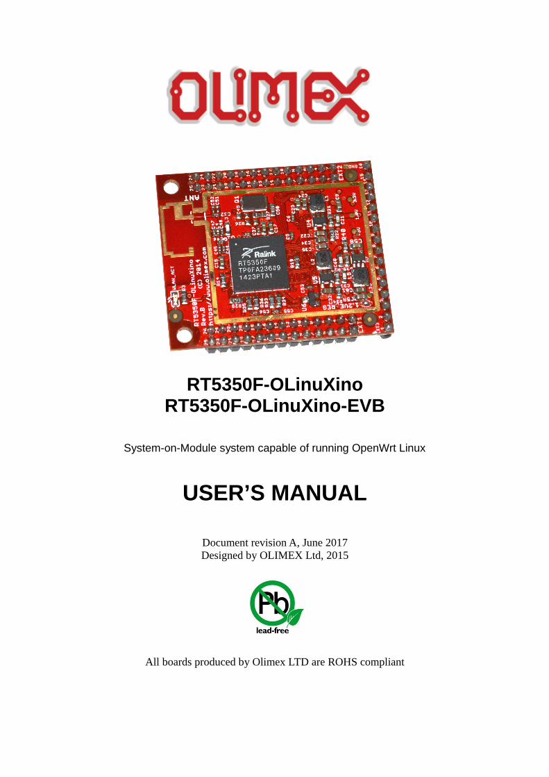
RT5350F-OLinuXinoRT5350F-OLinuXino-EVB
System-on-Module system capable of running OpenWrt Linux
USER’S MANUAL
Document revision A, June 2017Designed by OLIMEX Ltd, 2015
All boards produced by Olimex LTD are ROHS compliant
OLIMEX© 2017 RT5350F-OLinuXino user's manual
DISCLAIMER
© 2017 Olimex Ltd. Olimex®, logo and combinations thereof, are registered trademarks of Olimex Ltd. Other productnames may be trademarks of others and the rights belong to their respective owners.
The information in this document is provided in connection with Olimex products. No license, express or impliedor otherwise, to any intellectual property right is granted by this document or in connection with the sale ofOlimex products.
The hardware designs of both RT5350F-OLinuXino and RT5350F-OLinuXino-EVB development boards areconsidered OSHW (Open Source HardWare). The design source files are published online in popular format and freelyaccessible.
The parts of the software written by Olimex are released under GPL. The official images provided by Olimex maycontain propriety code that belongs to other parties. Such propriety code may be initially included in order todemonstrate the full functionality of the hardware, until open source alternatives become available.
It is possible that the pictures in this manual differ from the latest hardware revision of the board.
The product described in this document is subject to continuous development and improvements. All particulars of theproduct and its use contained in this document are given by OLIMEX in good faith. However all warranties implied orexpressed including but not limited to implied warranties of merchantability or fitness for purpose are excluded. Thisdocument is intended only to assist the reader in the use of the product. OLIMEX Ltd. shall not be liable for any loss ordamage arising from the use of any information in this document or any error or omission in such information or anyincorrect use of the product.
This evaluation board/kit is intended for use for engineering development, demonstration, or evaluation purposes onlyand is not considered by OLIMEX to be a finished end-product fit for general consumer use. Persons handling theproduct must have electronics training and observe good engineering practice standards. As such, the goods beingprovided are not intended to be complete in terms of required design-, marketing-, and/or manufacturing-relatedprotective considerations, including product safety and environmental measures typically found in end products thatincorporate such semiconductor components or circuit boards.
Olimex currently deals with a variety of customers for products, and therefore our arrangement with the user is notexclusive. Olimex assumes no liability for applications assistance, customer product design, software performance, orinfringement of patents or services described herein.
THERE IS NO WARRANTY FOR THE DESIGN MATERIALS AND THE COMPONENTS USED TO CREATE RT5350F-OLINUXINO AND RT5350F-OLINUXINO-EVB. THEY ARE CONSIDERED SUITABLE ONLY FOR RT5350F-OLINUXINO AND RT5350F-OLINUXINO-EVB, RESPECTIVELY.
Page 2 of 38
OLIMEX© 2017 RT5350F-OLinuXino user's manual
Table of ContentsDISCLAIMER ................................................................................................... 2CHAPTER 1: OVERVIEW ............................................................................... 5
1. Introduction to the chapter ......................................................................................... 51.1 Introduction to system-on-a-module design .......................................................... 51.2 Target market of the board ....................................................................................... 61.3 Features of R5350F-OLinuXino ................................................................................ 71.4 Features of R5350F-OLinuXino-EVB ....................................................................... 71.5 Board revisions used in the manual ........................................................................ 71.6 Document organization ............................................................................................. 8
CHAPTER 2: BOARD DESCRIPTION ............................................................ 92. Introduction to the chapter ......................................................................................... 92.1 Layouts ....................................................................................................................... 9
2.1.1 RT5350F-OLinuXino top view ..................................................................................................... 9
2.1.2 RT5350F-OLinuXino-EVB top view ........................................................................................... 10
2.2 Pinout RT5350F-OLinuXino (top view) .................................................................. 112.3 Pinout RT5350F-OLinuXino-EVB (top view) ......................................................... 12
CHAPTER 3: SETTING UP THE RT5350F BOARD ..................................... 133. Introduction to the chapter ....................................................................................... 133.1 Electrostatic and electrical polarity warnings ...................................................... 133.2 Requirements ........................................................................................................... 133.3 Preparing the OS to boot ........................................................................................ 14
3.3.1 Repairing the default image ...................................................................................................... 14
3.4 Powering the board ................................................................................................. 153.4.1 Mounted powering ..................................................................................................................... 15
3.4.2 Stand-alone powering of RT5350F-OLinuXino ........................................................................ 15
3.5 Button functions ...................................................................................................... 163.6 Interacting with the board ....................................................................................... 16
3.6.1 Basic setup of RT5350F-OLinuXino ......................................................................................... 16
3.7 Software support ..................................................................................................... 18
CHAPTER 4: THE RT5350F PROCESSOR ................................................. 194. Introduction to the chapter ....................................................................................... 194.1 The processor .......................................................................................................... 19
CHAPTER 5: CONTROL CIRCUITY ............................................................. 215. Introduction to the chapter ....................................................................................... 215.1 Reset ......................................................................................................................... 215.2 Clocks ....................................................................................................................... 215.3 Power supply circuit ................................................................................................ 21
CHAPTER 6: CONNECTORS AND PINOUT ................................................ 226. Introduction to the chapter ....................................................................................... 22
Page 3 of 38
OLIMEX© 2017 RT5350F-OLinuXino user's manual
6.1 Accessing RT5350F-OLinuXino and RT5350F-OLinuXino-EVB ......................... 226.2 UART0 header of RT5350F-OLinuXino-EVB ......................................................... 236.3 Connectors of RT5350F-OLinuXino ....................................................................... 24
6.3.1 EXT1 connector ......................................................................................................................... 25
6.3.2 EXT2 connector ......................................................................................................................... 25
6.3.3 EXT3 connector ......................................................................................................................... 26
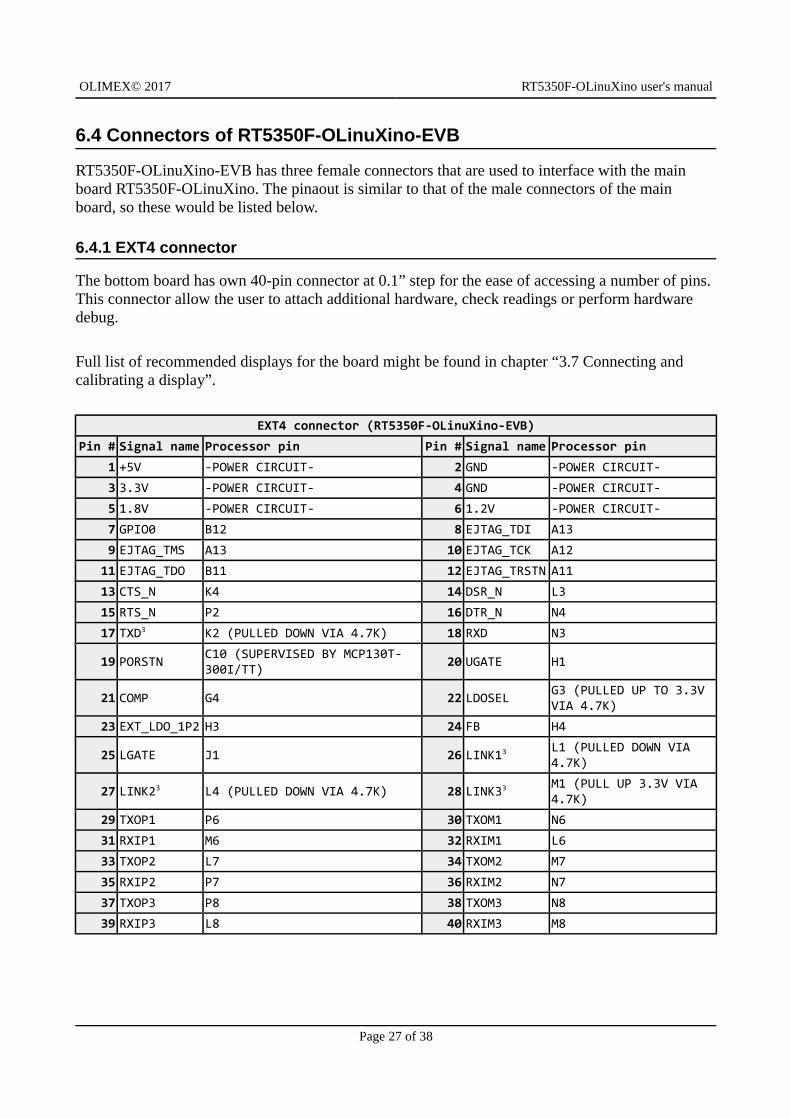
6.4 Connectors of RT5350F-OLinuXino-EVB .............................................................. 276.4.1 EXT4 connector ......................................................................................................................... 27
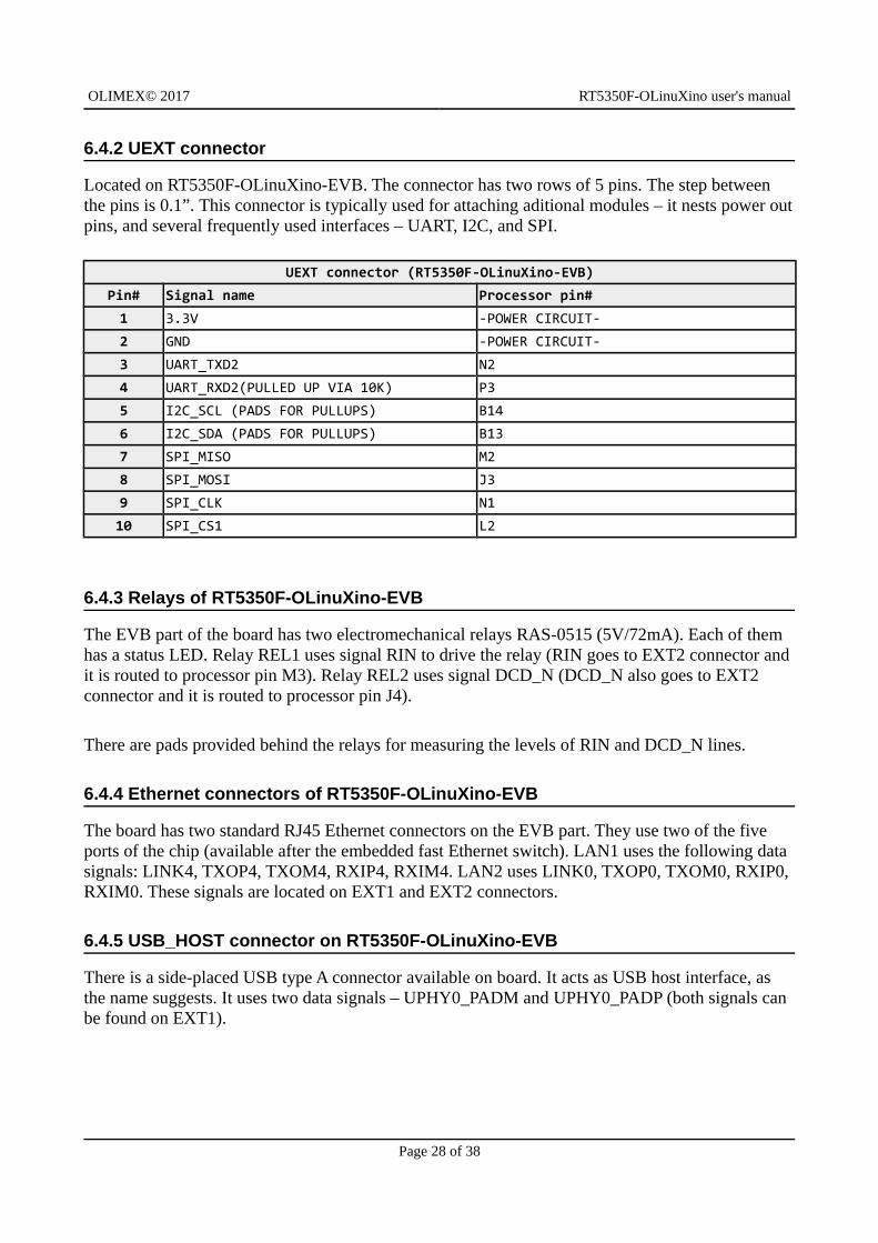
6.4.2 UEXT connector ......................................................................................................................... 28
6.4.3 Relays of RT5350F-OLinuXino-EVB ......................................................................................... 28
6.4.4 Ethernet connectors of RT5350F-OLinuXino-EVB .................................................................. 28
6.4.5 USB_HOST connector on RT5350F-OLinuXino-EVB .............................................................. 28
6.5 Additional hardware components .......................................................................... 29
CHAPTER 7: SCHEMATICS ......................................................................... 307. Introduction to the chapter ....................................................................................... 307.1 Eagle schematic ....................................................................................................... 30
CHAPTER 8: REVISION HISTORY AND SUPPORT .................................... 338. Introduction to the chapter ....................................................................................... 338.1 Document revision .................................................................................................. 338.2 Board revisions ........................................................................................................ 33
8.2.1 RT5350F-OLinuXino hardware revisions ................................................................................. 33
8.2.2 RT5350F-OLinuXino-EVB hardware revisions ........................................................................ 33
8.3 Useful web links ....................................................................................................... 348.4 How to purchase? .................................................................................................... 358.5 Order codes .............................................................................................................. 358.6 Frequently asked questions ................................................................................... 368.7 Quality control ......................................................................................................... 378.8 Product support ....................................................................................................... 38
Page 4 of 38
OLIMEX© 2017 RT5350F-OLinuXino user's manual
CHAPTER 1: OVERVIEW
1. Introduction to the chapter
Thank you for choosing this single-board computer from Olimex! This document provides a user’s guide for the RT5350F-OLinuXino and RT5350F-OLinuXino-EVB boards. As an overview, this chapter gives the scope of this document and lists the board’s features. The document’s organizationis then detailed.
The RT5350F-OLinuXino development board enables code development of applications running onthe RT5350F SoC microcontroller, manufactured by Ralink (a MediaTek's subsidiary company) from Taiwan.
The RT5350F-OLinuXino is typically used together with RT5350F-OLinuXino-EVB which features most of the peripherals and connectors needed for evaluation and utilization of the RT5350 SoC.
The hardware designs of RT5350F-OLinuXino and RT5350F-OLinuXino-EVB board are open-source, open-hardware and all documentation used for the hardware design and manufacturing is available to the customer.
The software written by Olimex for both boards is also open-source and released under GPL license.
1.1 Introduction to system-on-a-module design
The design of both RT5350F-OLinuXino and RT5350F-OLinuXino-EVB follows the system-on-a-module approach. A low-cost modular design which allows rapid product development and integration in own products. It is a two part system – a main part (smaller, multilayer, very densely populated) that nests the processor, the memory, the power control unit and a peripheral part (biggerand less densely populated) which contains the USB ports, the Ethernet connectors, most of the other connectors and interfaces. SOM designs are targeted at customers who want to apply custom modifications for own projects without having to deal with multilayer PCBs with controlled impedance and BGA assembly. This modular approach makes it possible to create simple 2-layer boards (that can be manufactured by your local PCB manufacturer) containing only the peripherals you need with the dimensions and shape suitable for your specific case.
Both the main part and the peripheral part of the SOM system have support in the official OpenWRT images distributed by Olimex and maintained by Olimex. These recommended images are typically available at the wiki articles of the board. Furthermore, the OpenWRT community recognizes the board and also provides official builds.
The hardware designs of both RT5350F-OLinuXino and RT5350F-OLinuXino-F are open source, unlike other Olimex SOM designs (where the design layout of the densely populated part is propriety).
Page 5 of 38
OLIMEX© 2017 RT5350F-OLinuXino user's manual
1.2 Target market of the board
The RT5350F-OLinuXino board is meant for people interested in single-board Linux computers with extended networking capabilities. The board is easily setup as web server. Basic electronics understanding and experience are recommended. Previous Linux experience and knowledge of OpenWRT are highly recommended.
Using the RT5350F-OLinuXino as a stand-alone development board would be more suitable for users with hardware experience or people already familiar with other single-board Linux boards anddesigns. As mentioned in the previous chapter the stand-alone board can be implemented in own hardware designs.
It is highly recommended to use RT5350F-OLinuXino with RT5350F-OLinuXino-EVB initially, unless you have previous experience with the same chip or similar boards manufactured by OLIMEX.
Some previous experience with OpenWRT is highly recommended.
Note that in the OLIMEX web-shop the product named “RT5350F-OLinuXino-EVB” includes the main board named “RT5350F-OLinuXino”.
RT5350F-OLinuXino is typically evaluated together with RT5350F-OLinuXino-EVB. In that case, the board's target market widens drastically – the combination is suitable for people familiar with OpenWRT, embedded systems enthusiasts, Linux gadget fans and also networking professionals (since its low cost and OpenWRT compatibility makes it a very good solution for application-orientated embedded systems with networking). The reason for this alteration is the additional hardware provided by RT5350F-OLinuXino-EVB. Generally, the processor's features become easier to access.
In which cases a RT5350F-OLinuXino is suitable for you:
1. The need to implement low-cost wireless and/or wired server or networking option to your end product using Linux-capable module
2. General-purpose performance and video output are not important for your task3. Interest in OpenWRT Linux or routers in general
In case you are looking for a board suitable for more of a general usage – it might be a good idea to take a look at other OLinuXino boards that provide more desktop-like experience (like A64-OLinuXino-eMMC, A20-OLinuXino-MICRO, or A20-OLiuXino-LIME2).
Page 6 of 38
OLIMEX© 2017 RT5350F-OLinuXino user's manual
1.3 Features of R5350F-OLinuXino
The RT5350F-OLinuXino board has the following set of features:
• RT5350F SoC – Ralink’s IEEE 802.11n draft compliant 1T1R MAC/BBP/PA/RF; 360 MHzMIPS24KEc CPU core; a 5-port integrated 10/100 Ethernet switch/PHY and a USB
• 32MB SDRAM• 8MB SPI NAND Flash• On-board antenna• WLAN activity LED• Power LED• x3 external connectors at convenient 0.1" step with all RT5350F signals• x3 external DCDC power converters releasing internal RT5350F vreg and preventing
common problem with overheating with this chip.• Two mounting holes• Suitable for embedding• Operating temperature: -10+55C• Size: (1600×1900)mils ~ (41×48)mm
1.4 Features of R5350F-OLinuXino-EVB
The RT5350F-OLinuXino-EVB board extends the hardware provided by RT5350F-OLinuXino in order to make it easier for initial evaluation with the following set of features:
• Barrel power jack for easier powering (5V only!)• USB 2.0 type A connector• 2×10/100 Mbps Ethernet ports with connectors• UART connector pins at 0.1" step for easier serial debugging• 2×15A/240VAC relays with connectors and status LEDs• User-programmable button• UEXT connector• JTAG pinholes exposed for chain programming• EXT connector at 0.1" step with the unused RT5350 signals• 27 GPIOs on a connector (24 free GPIOs)• 4 grounded mounting holes• Operating temperature: -10+55C• Dimensions: (4000×2500)mils ~ (102×64)mm
Note that the product named “RT5350F-OLinuXino-EVB” in our web-shop includes the main boardnamed “RT5350F-OLinuXino”.
1.5 Board revisions used in the manual
The documents follows the hardware layout of RT5350F-OLinuXino board revision D. RT5350F-OLinuXino-EVB revision B board of peripherals was used while writing this document. Different board revisions might have different features or settings. It is possible that parts of this document donot apply to all board revisions.
Page 7 of 38
OLIMEX© 2017 RT5350F-OLinuXino user's manual
1.6 Document organization
Each section in this document covers a separate topic, organized as follows:
– Chapter 1 is an overview of the board usage and features– Chapter 2 contains the general board diagram and layout
– Chapter 3 provides a guide for quickly setting up the board and software notes– Chapter 4 describes the component that is the heart of the board: the RT5350F SoC
– Chapter 5 is an explanation of the control circuitry associated with the microcontroller– Chapter 6 covers the connector pinout, peripherals and jumper description
– Chapter 7 provides the schematics and the dimensions of the board– Chapter 8 contains the revision history, useful links and support information
Page 8 of 38
OLIMEX© 2017 RT5350F-OLinuXino user's manual
CHAPTER 2: BOARD DESCRIPTION
2. Introduction to the chapter
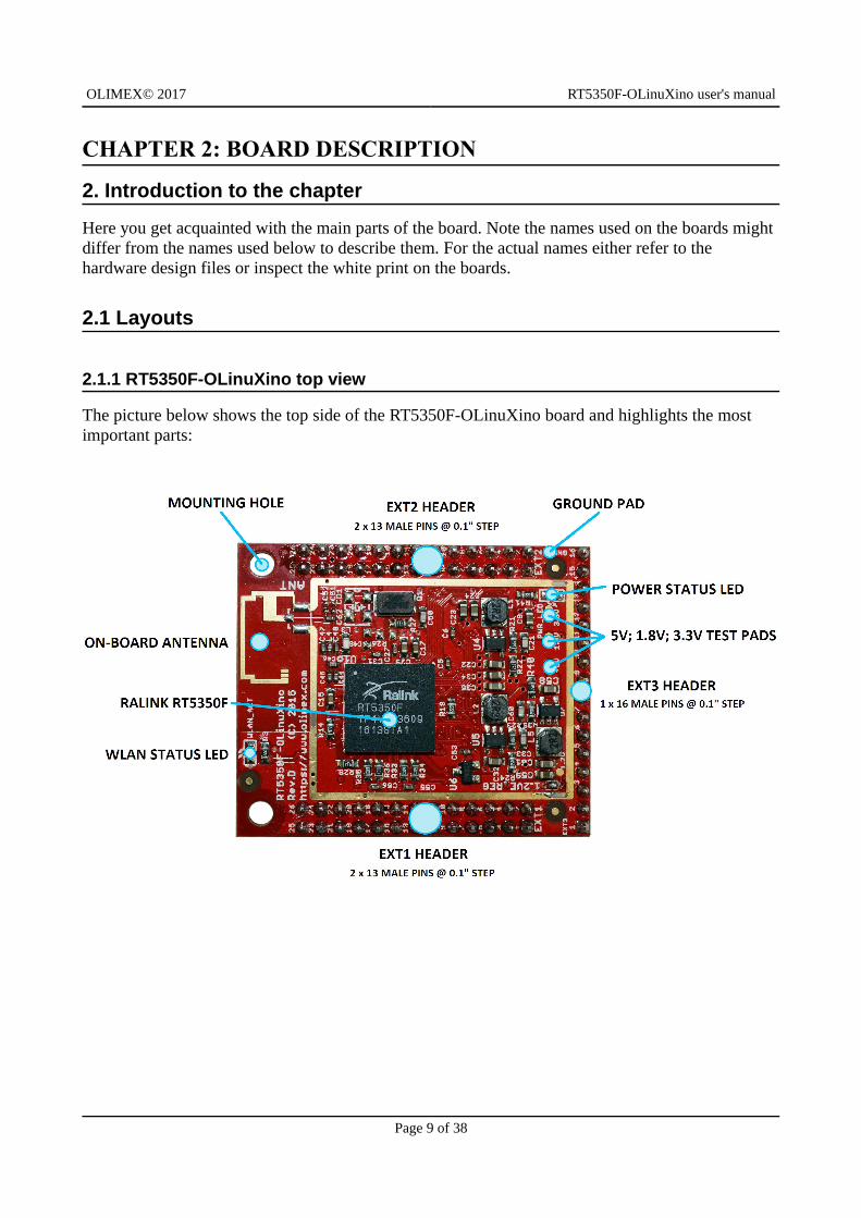
Here you get acquainted with the main parts of the board. Note the names used on the boards might differ from the names used below to describe them. For the actual names either refer to the hardware design files or inspect the white print on the boards.
2.1 Layouts
2.1.1 RT5350F-OLinuXino top view
The picture below shows the top side of the RT5350F-OLinuXino board and highlights the most important parts:
Page 9 of 38
OLIMEX© 2017 RT5350F-OLinuXino user's manual
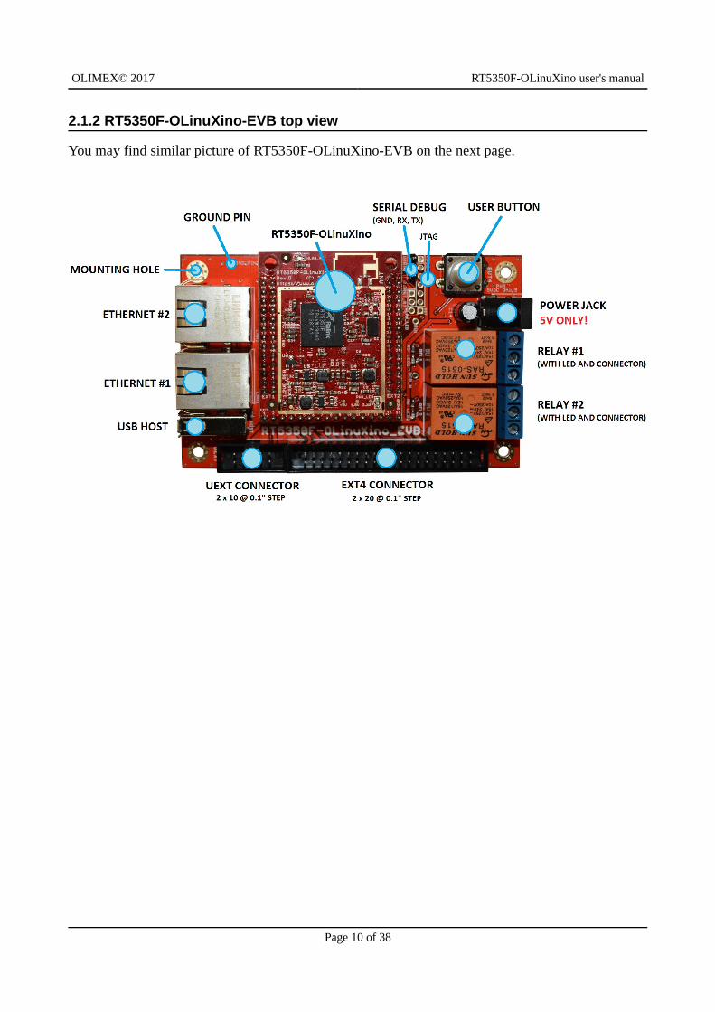
2.1.2 RT5350F-OLinuXino-EVB top view
You may find similar picture of RT5350F-OLinuXino-EVB on the next page.
Page 10 of 38
OLIMEX© 2017 RT5350F-OLinuXino user's manual
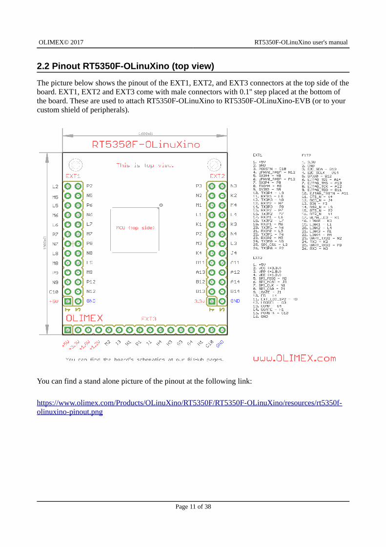
2.2 Pinout RT5350F-OLinuXino (top view)
The picture below shows the pinout of the EXT1, EXT2, and EXT3 connectors at the top side of theboard. EXT1, EXT2 and EXT3 come with male connectors with 0.1'' step placed at the bottom of the board. These are used to attach RT5350F-OLinuXino to RT5350F-OLinuXino-EVB (or to your custom shield of peripherals).
You can find a stand alone picture of the pinout at the following link:
https://www.olimex.com/Products/OLinuXino/RT5350F/RT5350F-OLinuXino/resources/rt5350f-olinuxino-pinout.png
Page 11 of 38
OLIMEX© 2017 RT5350F-OLinuXino user's manual
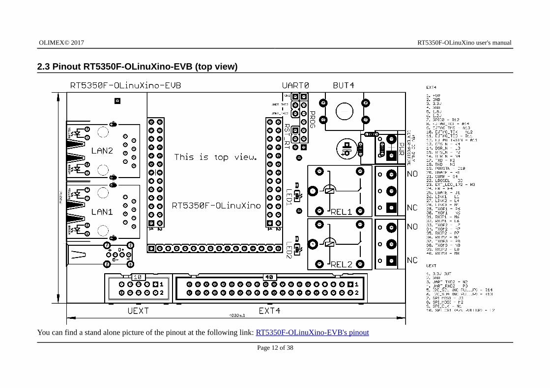
2.3 Pinout RT5350F-OLinuXino-EVB (top view)
You can find a stand alone picture of the pinout at the following link: RT5350F-OLinuXino-EVB's pinout
Page 12 of 38
OLIMEX© 2017 RT5350F-OLinuXino user's manual
CHAPTER 3: SETTING UP THE RT5350F BOARD
3. Introduction to the chapter
This section helps you set up the development board for the first time. Please consider first the electrostatic warning to avoid damaging the board, then discover the hardware and software required to operate the board.
The procedure to power up the board is given, and a description of the default board behavior is detailed.
3.1 Electrostatic and electrical polarity warnings
The RT5350F-OLinuXino and RT5350F-OLinuXino-EVB boards are shipped in protective anti-static cases. The boards must not be exposed to high electrostatic potentials. A grounding strap or similar protective device should be worn when handling the boards in an environment where there is a chance of electrostatic influence. Avoid touching the component pins or any other metallic element with bare hands.
Ensure that your development board gets attached to properly working hardware. If this is not possible please use isolators (like USB-ISO) to save your development board from potential over voltage.
If you connect other electrical devices to the board make sure that they have equal electrical polarity. For example, when you connect a serial cable between a PC and the board's UART pin it isa good idea to have them both connected to the same electrical source (to the same utility power socket). In rare cases different polarity might cause hardware damage to the board.
3.2 Requirements
In order to set up the RT5350F-OLinuXino-EVB board optimally one or more additional items maybe needed. They might be generally placed in two categories:
Required – items that are needed in order to achieve minimum functionality; Recommended – items that is good to have in order to be able to interact with the most important of the features of the board;
Note that if RT5350F-OLinuXino is used without RT5350F-OLinuXino-EVB – the requirements would be different! The requirements below are for the typical use of RT5350-OLinuXino-EVB.
Required items:
- 5V external power supply with proper connector – RT5350F-OLinuXino-EVB has a power jack – a DC barrel jack with a 2.0mm thick inner pin and the diameter of the hole is 6.3mm. The inner pin is the positive electrode.
Page 13 of 38
OLIMEX© 2017 RT5350F-OLinuXino user's manual
- Output device – USB↔SERIAL cable + personal computer with serial terminal program – RT5350-OLinuXino-EVB also has other options for debugging (SSH via the network interfaces, forexample), but these might require extra software configuration, so initially you would need a serial cable that would always work; the cable needs to have a converter in order to be compatible with the CMOS levels of the board's signals.
Some of the above-suggested items can be purchased by Olimex, for instance:
USB-SERIAL-CABLE-F – female USB serial adapter cable – provides the easiest way of debuggingBB-CH340T – USB serial adapter, open source hardware design, comes without wires
SY0605E – 5V power adapter suitable for 220V/50Hz power socket; with compatible power jackSY0605E-CHINA – cheaper version of a 5V power adapter suitable for 220V/50Hz power socket; with compatible power jack
3.3 Preparing the OS to boot
Olimex provides an official image for RT5350F-OLinuXino-EVB board – each board comes pre-programmed with this OpenWRT image on-board. Typically, you only need to attach serial cable and power the board.
Step-by-step instructions on how the images were prepared (and links to the resources used) are available at the bottom of the wiki article e: https://www.olimex.com/wiki/RT5350F-OLinuXino
The board is also recognized by the OpenWRT community. There are images and builds available atthe official OpenWRT repositories, compatible with Olimex RT5350F-OLinuXino and RT5350F-OLinuXino-EVB.
3.3.1 Repairing the default image
In case you have modified the memory with other image or you want to update the image you can always revert to the official image. There are two methods that we have described in detail at the wiki article – either by using the on-board u-boot menu or by using third party programmer. Refer to the wiki article for detailed instructions on how to proceed (https://www.olimex.com/wiki/RT5350F-OLinuXino).
Page 14 of 38
OLIMEX© 2017 RT5350F-OLinuXino user's manual
3.4 Powering the board
The powering requirements of the RT5350F-OLinuXino are different depending on whether you use it in stand-alone mode or mounted atop RT5350F-OLinuXino-EVB. The sub-chapters below deal with both scenarios.
3.4.1 Mounted powering
Typically, RT5350-OLinuXino gets evaluated when mounted atop RT5350-OLinuXino-EVB. In this case the former is powered via the latter. The power line, altogether with a number of other important processor lines, is transferred via the three headers EXT1, EXT2, and EXT3.
You need to provide 5V DC voltage to the power jack (named PWR) of RT5350F-OLinuXino-EVBboard. The DC barrel jack has 2.0mm inner pin and 6.3mm hole. More information about the exact component might be found here: https://www.olimex.com/wiki/PWRJACK
The typical consumption of RT5350F-OLinuXino + RT5350F-OLinuXino-EVB is around 0.15A @ 5V but might reach peaks up to 0.20A @ 5V during initial boot. These values were measured without anything else connected to the board (e.g. no keyboard, no mouse, etc).
Do not provide AC voltage to the RT5350F-OLinuXino board! Do not provide more than 5V of voltage directly to neither the RT5350F-OLinuXino nor RT5350F-OLinuXino-EVB boards! Providing 12V would instantly cause permanent hardware damage!
For the European customers, we also stock and sell basic power supply adapters compatible with the power jack.
It is always recommended to perform a soft “turn off” of the board.
If you disconnect the power supply before turning off the board you may corrupt the Linux file system.
Note that it is normal that when the board is powered some integrated circuits might appear hotter than others. This is perfectly normal for some electronic components – for instance – the voltage regulators and the main processor.
3.4.2 Stand-alone powering of RT5350F-OLinuXino
If you use only RT5350F-OLinuXino board (e.g. it is neither attached to RT5350F-OLinuXino-EVB nor to any other board of peripherals) the is only one options for powering it – using the male pins of EXT1. Provide +5V to pin #1 of EXT1 header; connect ground to pin #2 of the same EXT1 header. Double check the white print of the names of the header and the pins before applying any voltage! Make sure that you have properly identified EXT1 and EXT2 headers and pins #1 and #2!
The minimum power that your supply should be able to provide is 2W (equivalent of 0.4A of
Page 15 of 38
OLIMEX© 2017 RT5350F-OLinuXino user's manual
current at 5V of voltage). Note that there is no standard jack for the powering circuit but you might add own DC power jack.
Do not provide AC voltage to the RT5350F-OLinuXino board! Do not provide more than 5V of voltage directly to the RT5350F-OLinuXino board! Providing 12V would instantly cause permanenthardware damage!
3.5 Button functions
The RT5350F-OLinuXino has no buttons. The RT5350-OLinuXino-EVB board has only one – the user programmable button BUT4.
3.6 Interacting with the board
The typical and recommended way of interacting with RT5350F-OLinuXino and RT5350F-OLinuXino-EVB board is via a serial cable and a personal computer. The computer needs to be ableto recognize your cable and you need a serial terminal program. You would probably need a cable suitable for such a connection due to the fact that most personal computers lack a serial port nowadays. Even if you have serial port you should respect the CMOS levels of the board which are incompatible with the TTL levels of your computer.
We distribute ready-to-use plug-and-play cables that fit the criteria – one of them is called BB-CH430T and the other one is called USB-SERIAL-CABLE-F. Even if you already have such a cable or you decide to purchase it elsewhere it is advisable to visit the product pages for a reference.
There are other ways to connect to the board, once you are comfortable with it. For example, via theEthernet or WIFI using SSH protocol. Yet, this connection requires setting properly the software configuration, and it is possible to corrupt the output settings when connected over those interfaces and, thus, lose the output. In such cases, you can always use the serial cable as a reliable way to establish connection to the board.
3.6.1 Basic setup of RT5350F-OLinuXino
During typical evaluation of RT5350F-OLinuXino-EVB you need to connect the USB ↔ serial cable to the board's UART0 pins as follows: RX line to UART_TXD2 pin; TX line to UART_RXD2 pin; GND to GND (if using only RT5350F-OLinuXino you can find these signals on EXT2 header). Make sure that the serial cable is connected to your personal computer and recognized properly after driver installation. After the hardware connection is established, open a serial terminal program on the serial (COM) port which the cable is associated with. Famous serial terminal programs are “PuTTy”, “TeraTerm”, “Console”, “minicom”, etc. The typical baud rate is 57600, the rest of the settings should be left as per default.
After the serial connection, cable, and computer are set, you would need to power the board as explained in “3.4 Powering the board”. After applying the power supply, you should receive boot information on the serial terminal. In the command line interface of the official OpenWRT image you are automatically logged as root. You can test a few commands now and configure the WIFI.
Page 16 of 38
OLIMEX© 2017 RT5350F-OLinuXino user's manual
Type:
cat /etc/config/wireless
Enable the wireless server with:
uci set wireless.@wifi-device[0].disabled=0; uci commit wireless; wifi
This would create a WIFI network with SSID “OpenWRT”. Connect to the network and the board via a WIFI-capable device (for example, a laptop or a smartphone). Then start a web-browser and open 192.168.1.1 which would start the LuCI webUI – the graphical user control panel of the server, hosted on the RT5350F-OLinuXino board. Set up a password and explore the different options of the router.
More information for the initial software setup can be found here:
https://wiki.openwrt.org/doc/howto/firstlogin
and here:
https://wiki.openwrt.org/doc/howto/basic.config
Page 17 of 38

OLIMEX© 2017 RT5350F-OLinuXino user's manual
3.7 Software support
At the moment, we provide ready-to-use OpenWRT Linux images suitable for the flash memory of the board. We also provide instructions and sources of these releases. These images might be downloaded for free and modified as the user wishes. The latest images and updates are featured at the wiki article of the device: https://www.olimex.com/wiki/RT5350F-OLinuXino
We usually try to provide extra details and best experiences with our products at our wordpress page: http://olimex.wordpress.com/. Another useful place is the Olimex forums where a lot of people share their experience and advice: https://www.olimex.com/forum/.
The official images are a constant work-in-progress – newer releases are packed with better hardware support, newer kernels and extra features.
You are more than welcome to send or share your suggestions and ideas at our e-mail, the public forums or irc channel. We would attempt to help in almost every case. We listen to the feedback andif the majority of users suggest a software change or update we try to implement such. Customer feedback is very important for the overall state of the software support. However, do not expect full Linux software support.
We can share our experience. We can give you full details for things we have tried. We can point you to a resource or a guide. We can give you general directions to solving a specific problem or places to look for more information. However, we won’t install a piece of software for you or write custom program for you. We won't provide a specific software solution to a specific software problem.
Page 18 of 38
OLIMEX© 2017 RT5350F-OLinuXino user's manual
CHAPTER 4: THE RT5350F PROCESSOR
4. Introduction to the chapter
In this chapter is located the information about the heart of RT5350F-OLinuXino – its main processor. The information is a modified version of the datasheet provided by its manufacturers.
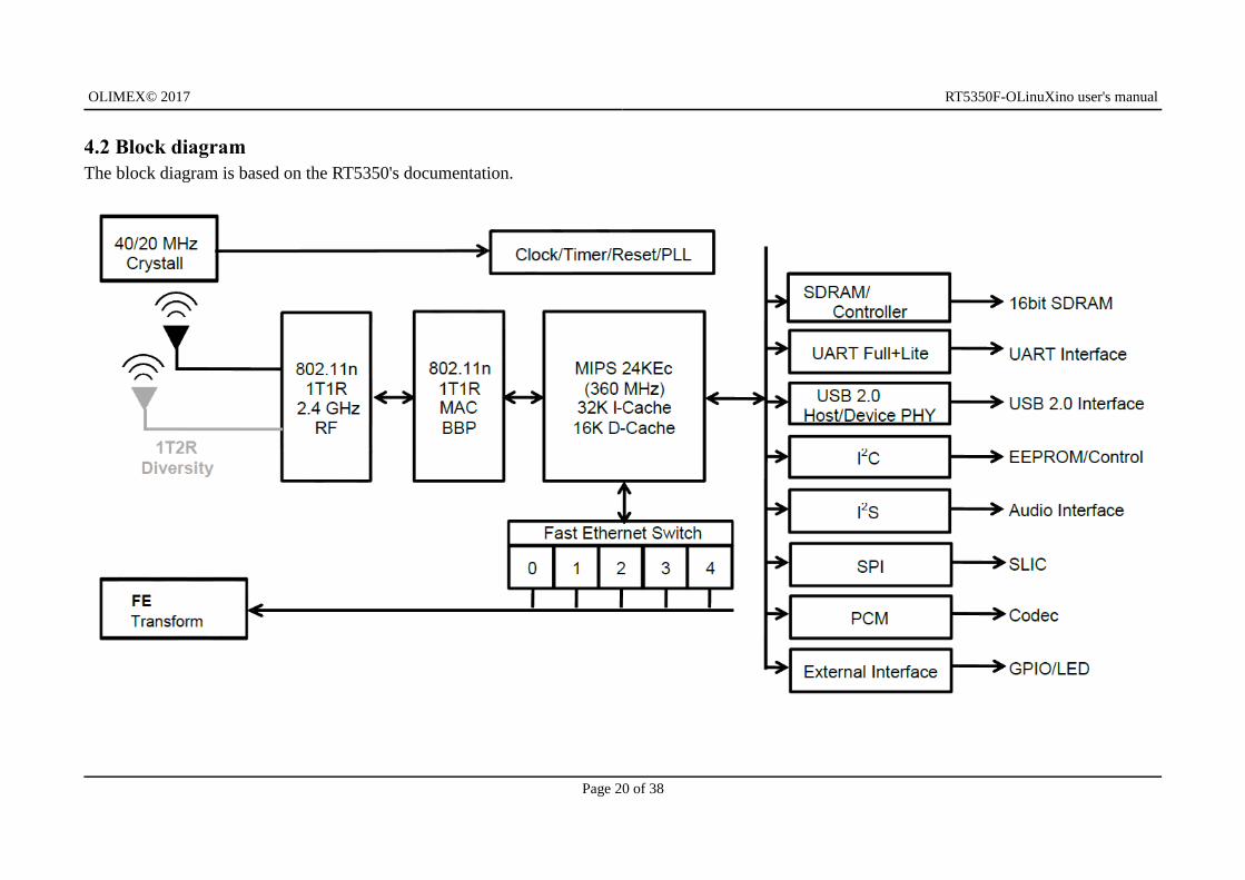
4.1 The processor
RT5350 is a system-on-a-chip processor – it packs a lot of features and requires only a few external components to create a wireless product. The embedded, high performance CPU can easily manage advanced applications such as Wi-Fi data processing without overloading the host processor. The chip also features a fast Ethernet switch, should you need wired networking. In addition, the RT5350 offers a variety of hardware interfaces (SPI/I2S/I2C/PCM/UART/USB) to support a range of possible applications. The software support for the features in the processor is at pretty good statethanks to the efforts of the community.
A short list of the features of the chip might be found below:
CPU: MIPS 24KEc 360 Mhz with 32 KB I cache/16KB D cache
Embedded 1T1R 2.4G CMOS RF Embedded 802.11n 1T1R MAC/BBP with MLD enhancement
Embedded 5-port 10/100 Mbps Ethernet switch and 5-port UTP PHY Embedded PA/LNA
150 Mbps PHY data rate 20 MHz/40 MHz channel width
Bluetooth Co-existence Multiple BSSID (up to 16)
WEP64/128, WPA, WPA2, WAPI engines QoS – WMM, WMM Power Save
Supports 802.11h TPC Supports 16-bit SDR SDRAM (up to 64 MB)
USB 2.0 host/device dual mode x1 Slow speed I/O: GPIO, SPI, I2C, I2S, PCM, UART, and JTAG
Rich on peripheral support and connectivity options
More information about the features of the processor can be found in its datasheet (also available at the Olimex GitHub repository):
https://github.com/OLIMEX/OLINUXINO/blob/master/HARDWARE/RT5350F/RT5350.pdf
Page 19 of 38
OLIMEX© 2017 RT5350F-OLinuXino user's manual
4.2 Block diagramThe block diagram is based on the RT5350's documentation.
Page 20 of 38
OLIMEX© 2017 RT5350F-OLinuXino user's manual
CHAPTER 5: CONTROL CIRCUITY
5. Introduction to the chapter
Here you can find information about hardware reset circuit and quartz crystals locations, the power supply circuit is also briefly discussed.
5.1 Reset
Neither RT5350F-OLinuXino, nor RT5350F-OLinuXino-EVB have hardware reset circuit implemented. Should you need hardware reset, you can use the two pinholes named “RST_RT” on the RT5350F-OLinuXino-EVB board (on the top side, near UART0 debug pins). “RST_RT” has two pinholes – the first one is routed to PORSTN (pin #15 of EXT3 connector; processor pin C10). Nearby you can also find a standalone RST pinhole exposed (only PORSTN).
It is a good practice to perform software reset of the board. Performing a hardware reset or power-cycling the board (reset by disconnecting and re-applying the main power supply) might lead to software corruption of the operating system.
5.2 Clocks
The board uses 20Mhz resonator Q2 (20MHz/9pF/10ppm). It is connected to pins A7 and B7 of the main chip.
The frequency is quite important for a fluent WIFI operation. If you face connectivity problems make sure to check this article:
https://github.com/OLIMEX/OLINUXINO/tree/master/SOFTWARE/RT5350F/Prebuilt%20images/mtd2%20recovery
5.3 Power supply circuit
The board requires 5V power supply. The different voltages required by the chip are derived from the 5V source via three step down regulators (SY8009AAAC). The RT5350-OLinuXino-EVB just adds a power jack to the design, in order to connect and disconnect the power supply easily. The power jack has 2.0mm thick inner pin. The outer hole diameter is 6.3mm. Refer to this wiki article for more information about the component used: https://www.olimex.com/wiki/PWRJACK
Make sure your power supply is capable of providing at least 0.5A of current at 5V of voltage (2.5W).
For more info on how to power the board refer to chapter “3.4 Powering the board”.
Page 21 of 38
OLIMEX© 2017 RT5350F-OLinuXino user's manual
CHAPTER 6: CONNECTORS AND PINOUT
6. Introduction to the chapter
In this chapter are presented the connectors that can be found on the board all together with their pinout and notes about them. Jumpers functions are described. Notes and info on specific peripherals are presented. Notes regarding the interfaces are given.
Overview images with the pinout can be found in “2.2 Pinout RT5350F-OLinuXino (top view)” and“2.3 Pinout RT5350F-OLinuXino-EVB (top view)”.
Stand-alone images with the pinount can also be found at the following locations: RT5350F-OLinuXino pinout and RT5350F-OLinuXino-EVB
6.1 Accessing RT5350F-OLinuXino and RT5350F-OLinuXino-EVB
The direct access method to the Linux command interface is via the serial debug interface. In the case of RT5350F-OLinuXino-EVB you would need to use the three pins of the UART0 header and then use your favorite terminal program (puTTy, minicom, picocom, teraterm, etc) to access the command line interface of the Linux. The board's connectors have the convenient 0.1” step which allows you to use a number of compatible cables (and breadboards).
Note that UART0 header and UEXT connector share same UART signals (UART_RXD2 and UART_TXD2). The logical voltage level of the UART is 3.3V.
If you want to access the RT5350F-OLinuXino only, then you can connect the serial cable to the EXT2 connector – pin #2 is GND; pin #23 is UART_TXD2; pin #25 is UART_RXD2. Remember that you would also need to power the board via the 5V power supply attached to EXT1 (EXT1's pin #1 is +5V; EXT1's pin #2 is GND).
In both scenarios you can use USB-SERIAL-CABLE-F with the serial interface that allows you to connect to a personal computer with a free USB port.
If you decide to make your own cable you would need to consider the 3.3V level of each signal available at the board's connector UART0 and you would need a convertor to reach the voltage level of your computer or cable! That is true for the RX and TX also!
It is highly recommended to have an USB-SERIAL-CABLE-F (or similar product) at hand when debugging – the other methods of accessing the board are not always reliable and might require additional configuration. You might be unable to access the board without a proper UART0 connection.
For more information please refer to chapter “3.5 Interacting with the board”.
Page 22 of 38
OLIMEX© 2017 RT5350F-OLinuXino user's manual
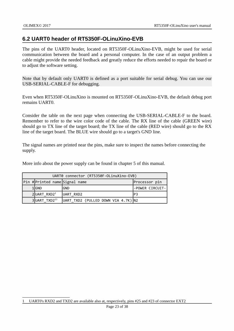
6.2 UART0 header of RT5350F-OLinuXino-EVB
The pins of the UART0 header, located on RT5350F-OLinuXino-EVB, might be used for serialcommunication between the board and a personal computer. In the case of an output problem acable might provide the needed feedback and greatly reduce the efforts needed to repair the board orto adjust the software setting.
Note that by default only UART0 is defined as a port suitable for serial debug. You can use ourUSB-SERIAL-CABLE-F for debugging.
Even when RT5350F-OLinuXino is mounted on RT5350F-OLinuXino-EVB, the default debug portremains UART0.
Consider the table on the next page when connecting the USB-SERIAL-CABLE-F to the board.Remember to refer to the wire color code of the cable. The RX line of the cable (GREEN wire)should go to TX line of the target board; the TX line of the cable (RED wire) should go to the RXline of the target board. The BLUE wire should go to a target's GND line.
The signal names are printed near the pins, make sure to inspect the names before connecting the supply.
More info about the power supply can be found in chapter 5 of this manual.
UART0 connector (RT5350F-OLinuXino-EVB)
Pin # Printed name Signal name Processor pin
1 GND GND -POWER CIRCUIT-
2 UART_RXD21 UART_RXD2 P3
3 UART_TXD213 UART_TXD2 (PULLED DOWN VIA 4.7K) N2
1 UART0's RXD2 and TXD2 are available also at, respectively, pins #25 and #23 of connector EXT2
Page 23 of 38
OLIMEX© 2017 RT5350F-OLinuXino user's manual
6.3 Connectors of RT5350F-OLinuXino
There are three connectors located on the bottom side of RT5350F-OLinuXino. They ease the access to processors pins. These connectors also provide a way to attach the board to a board of peripherals (like RT5350F-OLinuXino-EVB). The RT5350F-OLinuXino board has male connectors, while the bottom board has female connectors.
The power line at the EXT connectors that might be used as power input is the one named '+5V' available at the first pin of EXT1 and also the first pin of EXT3 connector. The rest of the power signals are outputs and it would be incorrect to try to power the board from there.
To keep the form factor as small as possible the GPIO and LCD_CON connectors have 0.05'' step.
IMPORTANT: The connectors are fragile – if you attempt to disconnect the board in one single pull or by pulling only one side out it might break! Furthermore – you might bend the board's pins! Use pliers or other suitable object as lever to disconnect the connectors carefully.
Below you would find tables with the signal at each pin. To understand better what each processor pin does it might be a good idea to refer to the schematics.
IMPORTANT: Some of the pins described below are used for the boot up sequence. Setting those pins improperly during power up might lead to start up problems.
Refer to the bottom-right corner of the schematic of the board for the boot up sequence configuration and options.
You can also find the pinout of the EXT connectors in a stand-alone document at the following link:
https://www.olimex.com/Products/OLinuXino/RT5350F/RT5350F-OLinuXino/resources/rt5350f-olinuxino-pinout.png
Page 24 of 38
OLIMEX© 2017 RT5350F-OLinuXino user's manual
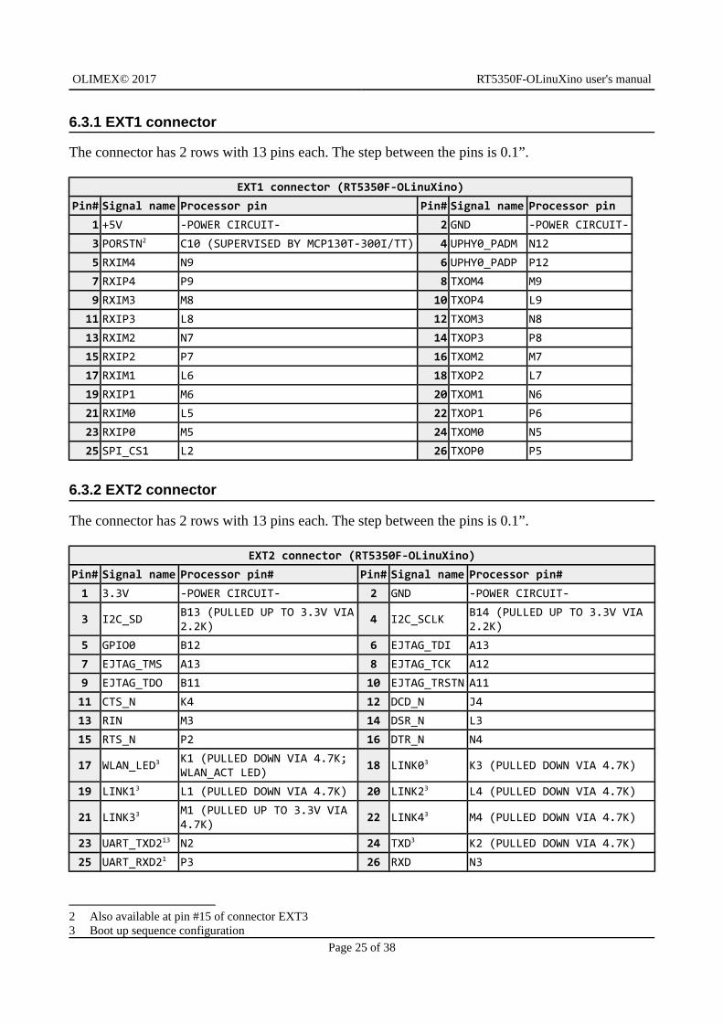
6.3.1 EXT1 connector
The connector has 2 rows with 13 pins each. The step between the pins is 0.1”.
EXT1 connector (RT5350F-OLinuXino)
Pin# Signal name Processor pin Pin# Signal name Processor pin
1 +5V -POWER CIRCUIT- 2 GND -POWER CIRCUIT-
3 PORSTN2 C10 (SUPERVISED BY MCP130T-300I/TT) 4 UPHY0_PADM N12
5 RXIM4 N9 6 UPHY0_PADP P12
7 RXIP4 P9 8 TXOM4 M9
9 RXIM3 M8 10 TXOP4 L9
11 RXIP3 L8 12 TXOM3 N8
13 RXIM2 N7 14 TXOP3 P8
15 RXIP2 P7 16 TXOM2 M7
17 RXIM1 L6 18 TXOP2 L7
19 RXIP1 M6 20 TXOM1 N6
21 RXIM0 L5 22 TXOP1 P6
23 RXIP0 M5 24 TXOM0 N5
25 SPI_CS1 L2 26 TXOP0 P5
6.3.2 EXT2 connector
The connector has 2 rows with 13 pins each. The step between the pins is 0.1”.
EXT2 connector (RT5350F-OLinuXino)
Pin# Signal name Processor pin# Pin# Signal name Processor pin#
1 3.3V -POWER CIRCUIT- 2 GND -POWER CIRCUIT-
3 I2C_SD B13 (PULLED UP TO 3.3V VIA2.2K)
4 I2C_SCLK B14 (PULLED UP TO 3.3V VIA 2.2K)
5 GPIO0 B12 6 EJTAG_TDI A13
7 EJTAG_TMS A13 8 EJTAG_TCK A12
9 EJTAG_TDO B11 10 EJTAG_TRSTN A11
11 CTS_N K4 12 DCD_N J4
13 RIN M3 14 DSR_N L3
15 RTS_N P2 16 DTR_N N4
17 WLAN_LED3 K1 (PULLED DOWN VIA 4.7K; WLAN_ACT LED)
18 LINK03 K3 (PULLED DOWN VIA 4.7K)
19 LINK13 L1 (PULLED DOWN VIA 4.7K) 20 LINK23 L4 (PULLED DOWN VIA 4.7K)
21 LINK33 M1 (PULLED UP TO 3.3V VIA 4.7K)
22 LINK43 M4 (PULLED DOWN VIA 4.7K)
23 UART_TXD213 N2 24 TXD3 K2 (PULLED DOWN VIA 4.7K)
25 UART_RXD21 P3 26 RXD N3
2 Also available at pin #15 of connector EXT33 Boot up sequence configuration
Page 25 of 38
OLIMEX© 2017 RT5350F-OLinuXino user's manual
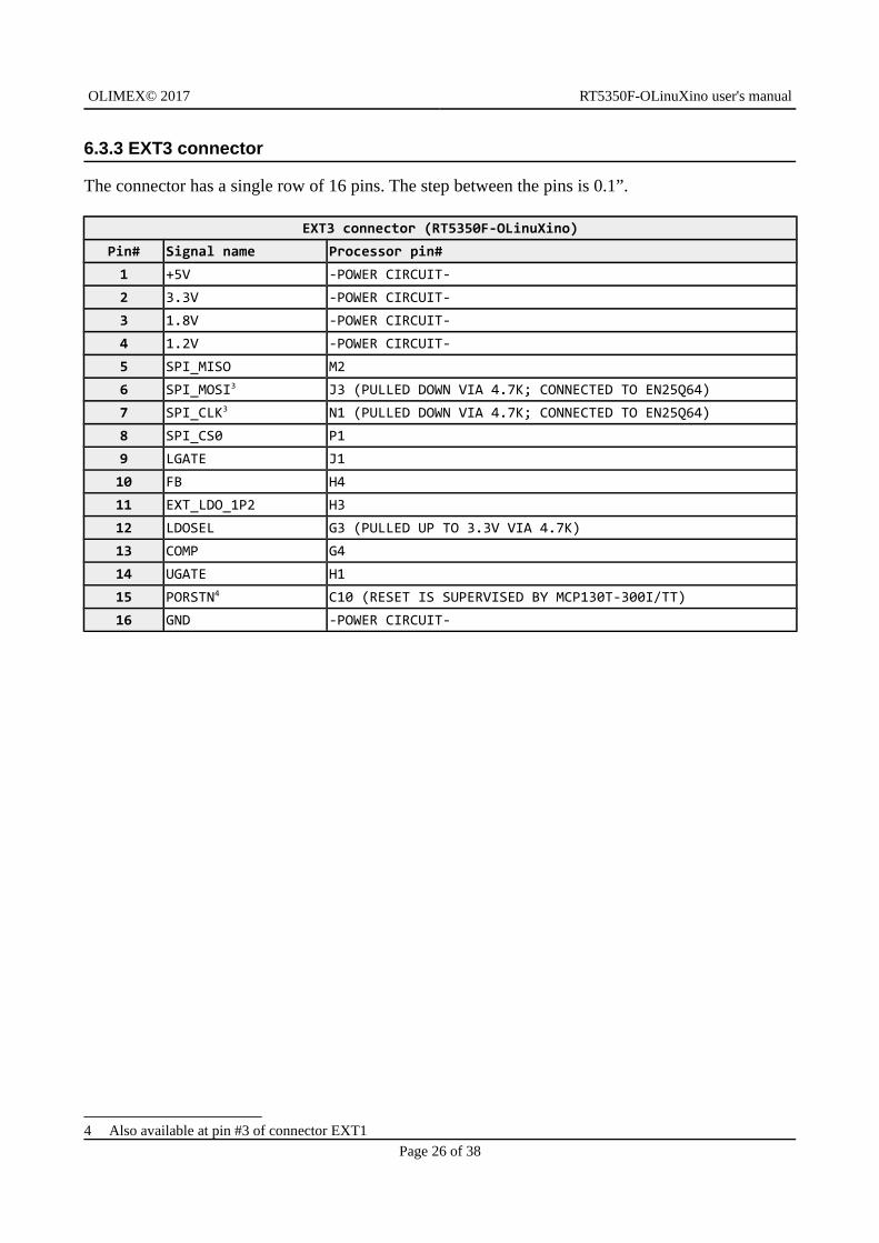
6.3.3 EXT3 connector
The connector has a single row of 16 pins. The step between the pins is 0.1”.
EXT3 connector (RT5350F-OLinuXino)
Pin# Signal name Processor pin#
1 +5V -POWER CIRCUIT-
2 3.3V -POWER CIRCUIT-
3 1.8V -POWER CIRCUIT-
4 1.2V -POWER CIRCUIT-
5 SPI_MISO M2
6 SPI_MOSI3 J3 (PULLED DOWN VIA 4.7K; CONNECTED TO EN25Q64)
7 SPI_CLK3 N1 (PULLED DOWN VIA 4.7K; CONNECTED TO EN25Q64)
8 SPI_CS0 P1
9 LGATE J1
10 FB H4
11 EXT_LDO_1P2 H3
12 LDOSEL G3 (PULLED UP TO 3.3V VIA 4.7K)
13 COMP G4
14 UGATE H1
15 PORSTN4 C10 (RESET IS SUPERVISED BY MCP130T-300I/TT)
16 GND -POWER CIRCUIT-
4 Also available at pin #3 of connector EXT1
Page 26 of 38
OLIMEX© 2017 RT5350F-OLinuXino user's manual
6.4 Connectors of RT5350F-OLinuXino-EVB
RT5350F-OLinuXino-EVB has three female connectors that are used to interface with the main board RT5350F-OLinuXino. The pinaout is similar to that of the male connectors of the main board, so these would be listed below.
6.4.1 EXT4 connector
The bottom board has own 40-pin connector at 0.1” step for the ease of accessing a number of pins. This connector allow the user to attach additional hardware, check readings or perform hardware debug.
Full list of recommended displays for the board might be found in chapter “3.7 Connecting and calibrating a display”.
EXT4 connector (RT5350F-OLinuXino-EVB)
Pin # Signal name Processor pin Pin # Signal name Processor pin
1 +5V -POWER CIRCUIT- 2 GND -POWER CIRCUIT-
3 3.3V -POWER CIRCUIT- 4 GND -POWER CIRCUIT-
5 1.8V -POWER CIRCUIT- 6 1.2V -POWER CIRCUIT-
7 GPIO0 B12 8 EJTAG_TDI A13
9 EJTAG_TMS A13 10 EJTAG_TCK A12
11 EJTAG_TDO B11 12 EJTAG_TRSTN A11
13 CTS_N K4 14 DSR_N L3
15 RTS_N P2 16 DTR_N N4
17 TXD3 K2 (PULLED DOWN VIA 4.7K) 18 RXD N3
19 PORSTNC10 (SUPERVISED BY MCP130T-300I/TT) 20 UGATE H1
21 COMP G4 22 LDOSELG3 (PULLED UP TO 3.3V VIA 4.7K)
23 EXT_LDO_1P2 H3 24 FB H4
25 LGATE J1 26 LINK13 L1 (PULLED DOWN VIA 4.7K)
27 LINK23 L4 (PULLED DOWN VIA 4.7K) 28 LINK33 M1 (PULL UP 3.3V VIA4.7K)
29 TXOP1 P6 30 TXOM1 N6
31 RXIP1 M6 32 RXIM1 L6
33 TXOP2 L7 34 TXOM2 M7
35 RXIP2 P7 36 RXIM2 N7
37 TXOP3 P8 38 TXOM3 N8
39 RXIP3 L8 40 RXIM3 M8
Page 27 of 38
OLIMEX© 2017 RT5350F-OLinuXino user's manual
6.4.2 UEXT connector
Located on RT5350F-OLinuXino-EVB. The connector has two rows of 5 pins. The step between the pins is 0.1”. This connector is typically used for attaching aditional modules – it nests power outpins, and several frequently used interfaces – UART, I2C, and SPI.
UEXT connector (RT5350F-OLinuXino-EVB)
Pin# Signal name Processor pin#
1 3.3V -POWER CIRCUIT-
2 GND -POWER CIRCUIT-
3 UART_TXD2 N2
4 UART_RXD2(PULLED UP VIA 10K) P3
5 I2C_SCL (PADS FOR PULLUPS) B14
6 I2C_SDA (PADS FOR PULLUPS) B13
7 SPI_MISO M2
8 SPI_MOSI J3
9 SPI_CLK N1
10 SPI_CS1 L2
6.4.3 Relays of RT5350F-OLinuXino-EVB
The EVB part of the board has two electromechanical relays RAS-0515 (5V/72mA). Each of them has a status LED. Relay REL1 uses signal RIN to drive the relay (RIN goes to EXT2 connector and it is routed to processor pin M3). Relay REL2 uses signal DCD_N (DCD_N also goes to EXT2 connector and it is routed to processor pin J4).
There are pads provided behind the relays for measuring the levels of RIN and DCD_N lines.
6.4.4 Ethernet connectors of RT5350F-OLinuXino-EVB
The board has two standard RJ45 Ethernet connectors on the EVB part. They use two of the five ports of the chip (available after the embedded fast Ethernet switch). LAN1 uses the following data signals: LINK4, TXOP4, TXOM4, RXIP4, RXIM4. LAN2 uses LINK0, TXOP0, TXOM0, RXIP0, RXIM0. These signals are located on EXT1 and EXT2 connectors.
6.4.5 USB_HOST connector on RT5350F-OLinuXino-EVB
There is a side-placed USB type A connector available on board. It acts as USB host interface, as the name suggests. It uses two data signals – UPHY0_PADM and UPHY0_PADP (both signals can be found on EXT1).
Page 28 of 38
OLIMEX© 2017 RT5350F-OLinuXino user's manual
6.5 Additional hardware components
The components below are mounted on the RT5350F-OLinuXino or RT5350F-OLinuXino-EVB butare not discussed above. They are listed here for completeness:
- PWR_LED (RT5350F-OLinuXino) – power identification LED – turns on upon powering the RT5350F-OLinuXino board;
- WLAN_ACT (RT5350F-OLinuXino) - indicates WLAN activity;
The components below are placed on RT5350F-OLinuXino-EVB:
- BUT4 button – user programmable – used to reset the board – drives signal GPIO0 (processor pin B12)
- PROG pinpholes – can be used for programming the board over the SPI (#1 – 3.3V; #2 – SPI_MISO; #3 – SPI_MOSI; #4 - SPI_CLK; #5 – SPI_CSO; #6 – GND; all of these signals can be found at EXT3 header); refer to the wiki entry on how to use a programmer like ARM-USB-OCD-H with the board: https://www.olimex.com/wiki/RT5350F-OLinuXino#Upload_prebuilt_images_using_programmer_tool
- RST pinhole – located next to PROG row of pinholes – connected to PORSTN signal and RST_RT pin #1
- RST_RT pinholes – consists of RST and GND pinholes – allows the addition of reset button
- GND_PIN pinhole – allows easier access to a GND signal
Page 29 of 38
OLIMEX© 2017 RT5350F-OLinuXino user's manual
CHAPTER 7: SCHEMATICS
7. Introduction to the chapter
In this chapter is located information about the schematics describing logically RT5350F-OLinuXino and RT5350F-OLinuXino-EVB.
7.1 Eagle schematic
RT5350F schematics may be found in the OLIMEX's GitHub repository: https://github.com/OLIMEX/OLINUXINO/tree/master/HARDWARE/RT5350F (each part of the modular design has own folder). You can download the whole repository as .zip without having a GitHub account.
You can find lower resolution exports of the schematics on the next two pages. The hardware revision of the exports might not be the latest. For an older or a newer hardware revision design files make sure to check the Git location linked above. If you are looking for a schematic of an olderrevision of the board and it isn't available at our web site you may request it by the support e-mail.
Page 30 of 38
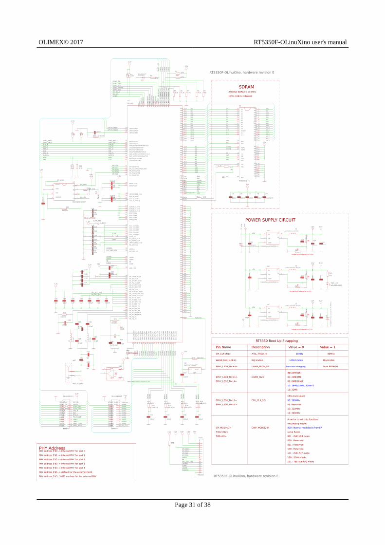
OLIMEX© 2017 RT5350F-OLinuXino user's manual
Page 31 of 38
PHY address 5'd0 -> Internal PHY for port 0
PHY address 5'd1 -> Internal PHY for port 1
PHY address 5'd2 -> Internal PHY for port 2
PHY address 5'd3 -> Internal PHY for port 3
PHY address 5'd4 -> Internal PHY for port 4
PHY address 5'd5 -> default for the external Port5
PHY address 5'd5...5'd31 are free for the external PHY
Close to RT5350
Close to RT5350
Re
Rf
Vout=0.6x(1+Re/Rf) = 3.32V
Re
Rf
Vout=0.6x(1+Re/Rf) = 1.83V
SDRAM256Mbit SDRAM / 133MHz
(4M x 16bit x 4Banks)
POWER SUPPLY CIRCUIT
RT5350 Boot Up Strapping
Pin Name Description Value = 0 Value = 1
SPI_CLK<N1> XTAL_FREQ_HI 20MHz 40MHz
WLAN_LED_N<K1> Big Endian Little Endian Big Endian
EPHY_LED4_N<M4> DRAM_FROM_EE from boot strapping from EEPROM
EPHY_LED3_N<M1>
EPHY_LED2_N<L4>
DRAM_SIZE
INIC/AP(SDR)
00: 2MB/8MB
01: 8MB/16MB
10: 16MB/32MB, 32MB*2
11: 32MB
EPHY_LED1_N<L1>
EPHY_LED0_N<K3>
CPU_CLK_SEL
CPU clock select
00: 360MHz
01: Reserved
10: 320MHz
11: 300MHz
SPI_MOSI<J3>
TXD2<N2>
CHIP_MODE[2:0]
A vector to set chip function/
test/debug modes
000 : Normal mode(boot fromSPI
serial flash)
001 : iNIC-USB mode
010 : Reserved
011 : Reserved
100 : Reserved
101 : iNIC-PHY mode
110 : SCAN mode
111 : TEST/DEBUG mode
TXD<K2>
PHY Address
Re
Rf
Vout=0.6x(1+Re/Rf) = 1.2V
RT5350F-OLinuXino, hardware revision E
RT5350F-OLinuXino, hardware revision E
1.2V
1 2
1.2VE
Open
1 2
1.2VE_REGClose
1.8V
3.3V
ANT
WIFI_RF_I-PEX
C1100nF
C2100nF
C3100nF
C4100nF
C5
100nF
C6
100nF
C7
100nF
C8
100nF
C9
22uF/6.3VC10
100nF
C121uF
C13100nF
C141uF
C151uF
C161uF
C171uF
C18100nF
C19100nF
C20100nF
C2122pFC22
22uF/6.3V
C23
22uF/6.3V
C2422uF/6.3V
C25100nF
C26100nF C27
100nFC2810pF
C291uF
C301uF
C3122nF
C3322pF
C36
1uF
C37
10pF
C38
1uF
C39
1uF
C40
100pF
C41
10pF
C42
100nF
C43
100pF
C44
2.7pF
C45
2.7pF
C47
1.2pFC48
1.2pFC49
NA(6.8pF)
C50
22pF
C51
NA
C52
NA
C53
100nF
C54
100nF
C55
100nF
C56
100nF
C57
100nF
C6022pF
C62
10pF
VDD
VSSOUT
E/D1
3
4
2
CD1
NA(20MHz/5032/20ppm/3.3V)
CS1
ML26HN2X13
EXT1
12
34
56
78
910
1112
1314
1516
1718
1920
2122
2324
2526
ML26HN2X13
EXT2
12
34
56
78
910
1112
1314
1516
1718
1920
2122
2324
2526
1
2
3
4
5
6
7
8
9
10
11
12
13
14
15
16
EXT3
HN1X16
GND
L12.2uH/1.5A/DCR<0.1R/CD32
L22.2uH/1.5A/DCR<0.1R/CD32
L52.2uH/1.5A/DCR<0.1R/CD32
+5V
+5V
PWR_LED
LED/RED/0603
Q1
E4SB20.000F20E15(20MHz/9pF/10ppm/5x3.2mm)
R12.2k
R22.2k R3
2.2k
R44.7k
R54.7k
R64.7k
R74.7k
R84.7k
R9NA
R104.7k
R114.7k
R12 8.2k/1%
R134.7k
R144.7k R15
4.7k
R164.7k
R1722R
R19 22R
R20
NA(47k)
R222.74k/1%
R241.1k/1%
R25
12k/1%R26
NA(1M)
R27330R
R28 NA(10k)
R299.1k/1%
R304.7k
R3149.9/1%
R3249.9/1%
R3349.9/1%
R3449.9/1%
R3549.9/1%
R3649.9/1%
R3749.9/1%
R3849.9/1%
R401.1k/1%
R41
2.2k
R424.7k
COMPG4
CTS_N/GPIO9/I2SSDOK4
DCDC-V33DJ2
DCDC_V33AH2
DCD_N/GPIO12/PCMCLK/TXDJ4
DSR_N/GPIO13/PCMDRX/CTS_NL3
DTR_N/GPIO11/PCMFS/RTS_NN4
EPHY_V33AK5
EPHY_V33AK6
EPHY_V33AK7
EPHY_V33AK8
EXT_LDO_1P2H3
FBH4
GND A1GND A4GND B2GND B4GND C2GND C3GND C4GND C5GND D2GND D3GND D4GND D5GND D6GND D7GND D8GND D9GND E2GND E4GND E5GND E6GND E7GND E8GND E9GND F1GND F2GND F3GND F4GND F6GND F7GND F8GND G6GND G7GND G8GND H6GND H7GND H8GND J6GND J7GND J8GND J9GND K9GND K10GND L10GND M10GND M11GND M12GND N10GND N13GND N14GND P10GND P14
LDOSELG3
LDO_V18AG2
LGATEJ1
MA0 G14MA1 H13MA2 H12MA3 H11MA4 J14MA5 J13MA6 J12MA7 K14MA8 K13MA9 J11MA10 L14MA11 K12MA12 L13
MBA0L12MBA1M14
MCAS_NC12
MCKE C11
MCLK H14
MCS0_NK11MCS1_N/REFCLK0_OUTC14
MD0 E10MD1 D11MD2 D12MD3 D13MD4 D14MD5 E11MD6 F11MD7 E12MD8 F12MD9 E13MD10E14MD11G11MD12G12MD13F13MD14G13MD15F14
MDQM0J10MDQM1M13
MRAS_NL11
MWE_NC13
PLL_AVDD_V12AA10
PLL_DVDD_V12DB10
PORST_NC10
RIN/GPIO14/PCMDTX/RXDM3
RTS_N/GPIO7/I2SCLKP2
RXD/GPIO10/I2SSDIN3
RXD2/GPIO16P3
SDRAM_IO_V33DH10
SDRAM_IO_V33DG10
SDRAM_IO_V33DF10
SOC_CO_V12DG9
SOC_CO_V12DH5
SOC_CO_V12DF9
SOC_CO_V12DJ5
SOC_CO_V12DH9
SOC_IO_V33DF5
SOC_IO_V33DG5
SOC_IO_V33D_1D10
SPI-CS0/GPIO3P1
SPI_CLK/GPIO4N1
SPI_CS1/GPIO27/WDT_RSTL2
SPI_MISO/GPIO6M2
SPI_MOSI/GPIO5J3
TXD/GPIO8/I2SWSK2
TXD2/GPIO15N2
UGATEH1
UPHY0_PADMN12
UPHY0_PADPP12
UPHY0_VDDA_V33AN11
UPHY0_VDDL_V12DP13
UPHY0_VRESP11
VOUT_1P2G1
WL_ADC_V12B9
WL_BG_RES_12KB8
WL_BG_V33AA9
WL_LDOPLL_OUT_V12C7
WL_LDORF_IN_VXA8
WL_LDORF_OUT_V12C8
WL_PLL_V12AB6
WL_PLL_VC_CAPA6
WL_PLL_X1A7
WL_PLL_X2B7
WL_RF0_2G_INNA3
WL_RF0_2G_INPA2
WL_RF0_IF_V12AB5
WL_RF0_PA1_V33AE3
WL_RF0_PA_OUTND1
WL_RF0_PA_OUTPC1
WL_RF0_PA_V33NE1
WL_RF0_PA_V33PB1
WL_RF0_RF_V12AB3
WL_RF_BB1_V12AA5
WL_RF_BB2_V12C9
WL_VCO_VCO_V12AC6
U1
RT5350
U2
W9825G6JH-6
A023
A124
A225
A326
A429
A530
A631
A732
A833
A934
A10/AP22
A1135
A1236
BA020
BA121
CAS17
CKE37
CLK38
CS19
DQ0 2DQ1 4DQ2 5DQ3 7DQ4 8DQ5 10DQ6 11DQ7 13DQ8 42DQ9 44DQ10 45DQ11 47DQ12 48DQ13 50DQ14 51DQ15 53
DQMH39
DQML15
NC140
RAS18
VDD1 1VDD2 14VDD3 27VDDQ13VDDQ29VDDQ343VDDQ449
VSS1 28VSS2 41VSS3 54VSSQ16VSSQ212VSSQ346VSSQ452
WE16
U3
EN25Q64-104HIP
/CS/1
/HOLD/IO37
/WP/IO23
CLK6
DI/IO05DO/IO12
GND4
VCC8
EN1 FB 5
GND2
IN4 LX 3
U4
SY8009AAAC(SOT23-5)
EN1 FB 5
GND2
IN4 LX 3
U5
SY8009AAAC(SOT23-5)
GND
VCC RESET12
U6MCP130T-300I/TT
EN1 FB 5
GND2
IN4 LX 3
U7
SY8009AAAC(SOT23-5)
3.3V
3.3V
3.3V
3.3V
1.2V
3.3V
3.3V
1.8V3.3V
1.8V
3.3V
3.3V
3.3V
3.3V
1.2V
3.3V
1.8V3.3V 1.2V 3.3V
3.3V
3.3V
WLAN_ACTLED/Yellow/0603
Z2
SMAZ5V6-TP(Farnell_PN-1924469)
+5V
+5V
+5V
A0
A0
A1
A1
A2
A2
A3
A3
A4
A4
A5
A5
A6
A6
A7
A7
A8
A8
A9
A9
A10
A10
A11
A11
A12
A12
BA0
BA0
BA1
BA1
CAS
CAS
COMP
COMP
CS
CS
CS1
CS1
CTS_NCTS_N
CTS_N
D0
D0D1 D1D2
D2
D3 D3D4 D4D5
D5D6D6D7
D7
D8 D8D9
D9D10
D10
D11
D11
D12 D12D13 D13D14
D14
D15 D15
DCD_NDCD_N
DCD_N
DQM0
DQM0
DQM1
DQM1
DSR_NDSR_N
DSR_N
DTR_NDTR_N
DTR_N
EJTAG_TCK
EJTAG_TCK
EJTAG_TDI
EJTAG_TDI
EJTAG_TDO
EJTAG_TDO
EJTAG_TMS
EJTAG_TMS
EJTAG_TRSTN
EJTAG_TRSTN
EXT_LDO_1P2
EXT_LDO_1P2
FB
FB
GPIO0
GPIO0
I2C_SCLK
I2C_SCLK
I2C_SD
I2C_SD
LDOSEL
LDOSEL
LGATE
LGATE
LINK0LINK1LINK2LINK3LINK4
PLL_VCC_1V2
PORSTN
PORSTN
PORSTN
RAS
RAS
RF_VCC_1V2
RINRIN
RIN
RTS_NRTS_N
RTS_N
RXDRXD
RXD
RXIM0
RXIM1
RXIM2
RXIM3
RXIM4
RXIP0
RXIP1
RXIP2
RXIP3
RXIP4
SPI_CLK
SPI_CLK
SPI_CLK
SPI_CS0
SPI_CS0
SPI_CS0
SPI_CS1
SPI_CS1
SPI_MISO
SPI_MISO
SPI_MISO
SPI_MOSI
SPI_MOSI
SPI_MOSI
TXDTXD
TXD TXOM0
TXOM1
TXOM2
TXOM3
TXOM4
TXOP0
TXOP1
TXOP2
TXOP3
TXOP4
UART_RXD2UART_RXD2
UART_RXD2
UART_TXD2UART_TXD2
UART_TXD2
UGATE
UGATE
UPHY0_PADM
UPHY0_PADM
UPHY0_PADP
UPHY0_PADP
WE
WE
WLAN_LED
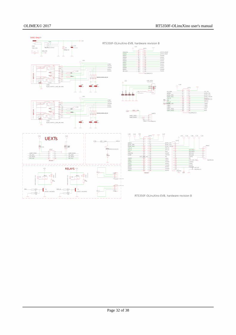
OLIMEX© 2017 RT5350F-OLinuXino user's manual
Page 32 of 38
5VDC Only!!!
RELAYS
UEXTs
+-
RT5350F-OLinuXino-EVB, hardware revision B
RT5350F-OLinuXino-EVB, hardware revision B
BUT4DTSM24R(12x12x10)
C11100nF
C12100nF
C13100nF
C14
470uF/10V/105C
C87100nF
C88100nF
C89100nF
1
2
3
CON1
CON3-DG306-5.0_3P(TB3-5MM)
1
2
3
CON2
CON3-DG306-5.0_3P(TB3-5MM)
D21N5819(S4SOD-123)
D3
SMBJ6.0A
D8D9
DCD_N
1 2
3 4
5 6
7 8
9 10
11 12
13 14
15 16
17 18
19 20
21 22
23 24
25 26
EXT1
ML26PN2X13
1 2
3 4
5 6
7 8
9 10
11 12
13 14
15 16
17 18
19 20
21 22
23 24
25 26
EXT2
ML26PN2X13
1
2
3
4
5
6
7
8
9
10
11
12
13
14
15
16
EXT3
PN1X16
1 2
3 4
5 6
7 8
9 10
11 12
13 14
15 16
17 18
19 20
21 22
23 24
25 26
27 28
29 30
31 32
33 34
35 36
37 38
39 40
EXT4
BH40S
GND_PIN
L9FB0805/600R/2A
7575
7575
1nF/2kV
1:1
1:1
1452
3786
GREEN
YELLOW
GND
AGAG
AYAY
COM3
KGKG
KYKY
NC6
RD+7
RD-8
TD+1
TD-2
LAN1RJLBC-060TC1_GND_MILLING
7575
7575
1nF/2kV
1:1
1:1
1452
3786
GREEN
YELLOW
GND
AGAG
AYAY
COM3
KGKG
KYKY
NC6
RD+7
RD-8
TD+1
TD-2
LAN2RJLBC-060TC1_GND_MILLING
+5V
+5V
+5V
+5V
+5V +5V
+5V
1
2
3
4
5
6
PROG
NA(PN1X6)
PWR
YDJ-1136
1
2
PWR.
NA(TB2/3.5mm)
R1560R
R2NA
R3 10k
R4560R
R52.2k
R62.2k
R131k
R1410k
R151k
R1610k
R53NA
R54560R
R64 10k
R82NA(2.2k)
R83NA(2.2k)
R8447k
RAS-05-15
REL1
REL1
RAS-05-15
REL2
REL2
RIN
NA(RA1206_(4X0603)_4B8_51R)NA(RA1206_(4X0603)_4B8_51R)NA(RA1206_(4X0603)_4B8_51R)NA(RA1206_(4X0603)_4B8_51R)
NA(RA1206_(4X0603)_4B8_51R)NA(RA1206_(4X0603)_4B8_51R)NA(RA1206_(4X0603)_4B8_51R)NA(RA1206_(4X0603)_4B8_51R)
RST
1
2RST_RT
NA(HN1x2)
T1
BC817-40(SMD)
T2
BC817-40(SMD)
1
2
3
UART0
HN1X3
1 2
3 4
5 6
7 8
9 10
UEXT
BH10S
SHIELD
1
2
3
4
USB_HOSTUSB_A_VERTICAL
3.3V
3.3V
3.3V
1.8V
1.8V 1.2V
1.8V
3.3V
3.3V 3.3V
3.3V
1.8V 1.2V3.3V
3.3V
3.3V
WLAN_LED
COMP
COMP
CTS_N
CTS_N
DCD_N
DCD_N
DSR_N
DSR_N
DTR_N
DTR_N
EJTAG_TCK
EJTAG_TCK
EJTAG_TDI
EJTAG_TDI
EJTAG_TDO
EJTAG_TDO
EJTAG_TMS
EJTAG_TMS
EJTAG_TRSTN
EJTAG_TRSTN
EXT_LDO_1P2
EXT_LDO_1P2FB
FB
GPIO0
GPIO0GPIO0
I2C_SCL
I2C_SCL
I2C_SDA
I2C_SDA
LDOSEL
LDOSELLGATE
LGATE
LINK0
LINK0
LINK1
LINK1
LINK2
LINK2
LINK3
LINK3
LINK4
LINK4
PORSTN
PORSTN
PORSTN
RIN
RIN
RTS_N
RTS_N
RXD
RXD
RXIM0
RXIM0
RXIM1
RXIM1
RXIM2
RXIM2
RXIM3
RXIM3
RXIM4
RXIM4RXIP0
RXIP0
RXIP1
RXIP1
RXIP2
RXIP2
RXIP3
RXIP3
RXIP4
RXIP4
SPI_CLK
SPI_CLK
SPI_CS0
SPI_CS1
SPI_CS1
SPI_MISO
SPI_MISO
SPI_MOSI
SPI_MOSI
TXD
TXD
TXOM0
TXOM0
TXOM1
TXOM1
TXOM2
TXOM2
TXOM3
TXOM3
TXOM4
TXOM4
TXOP0
TXOP0
TXOP1
TXOP1
TXOP2
TXOP2
TXOP3
TXOP3
TXOP4
TXOP4
UART_RXD2
UART_RXD2
UART_RXD2
UART_TXD2
UART_TXD2
UART_TXD2
UGATE
UGATE
UPHY0_PADM
UPHY0_PADM
UPHY0_PADP
UPHY0_PADP
WLAN_LED
OLIMEX© 2017 RT5350F-OLinuXino user's manual
CHAPTER 8: REVISION HISTORY AND SUPPORT
8. Introduction to the chapter
In this chapter you will find the current and the previous version of the document you are reading. Also the web-page for your device is listed. Be sure to check it after a purchase for the latest available updates and examples.
8.1 Document revision
Document revision Changes Modified page
A, 07.06.17 Initial manual release All
8.2 Board revisions
Remember to check the schematics and the board design files to compare the differences.
8.2.1 RT5350F-OLinuXino hardware revisions
Board revision Notable changes
B Initial hardware revision of the board
C
1. Added power LED to the 3.3V line2. Added Zener diode Z1 -> DDZ9678-7(SOD-123)_Farnell_PN-18586313. Added 5.6V Zener diode to +5V4. Changed the value of the quartz from 20ppm to 10 ppm E4SB20.000F20E15(20MHz/10pF/10ppm/5×3.2mm)5. Changed C49 from NA to 6.8pF and C50 from 27pF to 22pF.
D1. Added CD1 oscillator for testing purposes2. Added R42 (4.7k) pull-up on EPHY_LED2_N and changed R7 to NA
E1. Changed value of R42 to NA (down from 4.7K)2. R9 value changed to NA (down from 4.7K)3. C49 value changed to NA (down from 6.8pF)
8.2.2 RT5350F-OLinuXino-EVB hardware revisions
Board revision Notable changes
B Initial hardware revision of the board
Page 33 of 38
OLIMEX© 2017 RT5350F-OLinuXino user's manual
8.3 Useful web links
The web pages you can visit for more information about RT5350F-OLinuXino are:
https://www.olimex.com/Products/OLinuXino/RT5350F/RT5350F-OLinuXino/ and https://www.olimex.com/Products/OLinuXino/RT5350F/RT5350F-OLinuXino-EVB/
Wiki article of the boards: https://www.olimex.com/wiki/RT5350F-OLinuXino
Wiki article at the OpenWRT site: https://wiki.openwrt.org/toh/olimex/rt5350f-olinuxino-evb
You can get the latest hardware updates at the GitHub page: https://github.com/OLIMEX/OLINUXINO/tree/master/HARDWARE/RT5350F
A place for general questions, FAQ or friendly talk: https://www.olimex.com/forum/
You may may join our IRC channel #olimex @ freenode.net (http://webchat.freenode.net/?channels=olimex).
Page 34 of 38
OLIMEX© 2017 RT5350F-OLinuXino user's manual
8.4 How to purchase?
You can purchase directly from our online shop or from any of our distributors. Note that usually it might be faster and cheaper to purchase Olimex products from our distributors. List of confirmed Olimex LTD distributors and resellers: https://www.olimex.com/Distributors.
Please visit https://www.olimex.com/ for more info.
8.5 Order codes
Short summary of the formal product names of the devices mentioned in this document:
RT5350F-OLinuXino – the target of this manual
RT5350F-OLInuXino-EVB – RT5350F-OLinuXino + RT5350F-OLinuXino-EVB – the main board with board with all important peripherals that makes it easier access chip's resources (two Ethernet connectors; USB HOST connector; two relays with status LEDs; a power jack; UEXT; 0.1'' step GPIO connectors; etc)
USB-SERIAL-CABLE-F – USB serial console cable with female leads
Page 35 of 38
OLIMEX© 2017 RT5350F-OLinuXino user's manual
8.6 Frequently asked questions
Q: I just received the product. How to establish basic connection with the board?
Connect USB<->serial cable between the UART0 pins of the board and your personal computer. Open your favorite serial terminal software on the COM port, created by your USB<->serial cable. The baud rate for the connection is 57600. Power RT5350F-OLinuXino-EVB using the PWR barreljack (5V DC only!).
Q: I see only 16MB RAM listed in OpenWRT! The board is supposed to have 32MB RAM! Did I get a defective board? What should I do in order to see 32MB RAM?
The board should be fine – during the production tests the amount of RAM listed in OpenWRT gets verified by a technician. Usually there are three ways to fix this issue:
1) Unpower the board. Disconnect your serial cable from the board. Power the board and wait 30 seconds then connect the serial cable. The whole 32MB of RAM memory should be available now. Some noisy serial cables might alter the levels of the board, which affects the bootstrap configuration.
2) Purchase a better USB <-> serial cable. Our serial cables (USB-SERIAL-CABLE-F) should work fine.
3) Disconnect the power supply from the board. Connect pin #27 from EXT4 connector to pin #3 ofthe same connector via a 1K resistor. After the connection is established apply power to the board. This forces a 32MB-only bootstrap configuration – this alteration just pulls up LINK2 (since LINK3 is already pulled-up). Refer to the datasheet of RT5350 for more information.
Page 36 of 38
OLIMEX© 2017 RT5350F-OLinuXino user's manual
8.7 Quality control
Each board designed and manufactured by Olimex passes a number of tests to ensure it is working properly. There are tests performed before and after assembly.
Before assembly:
- the PCB of each the boards passes electrical test for obvious short circuits
- the bigger components get tested for obvious manufacturing problems
If there is a problem with a board PCB components before assembly the faulty PCB or the faulty component typically go directly to the trash.
The largest part of the assembly is usually performed by automatic SMT placing machines. Yet, some components can be placed only by hand (plastic connectors, for example).
Tests performed after assembly:
- the board passes automatized optical inspection for component misplacement and soldering issues.- the board gets inspected visually by a technician
- the assembled board passes electrical tests performed by a technician- the board passes software tests performed by a technician; the software checks every peripheral, and every free pin of the board (via additional hardware headers, specifically designed for testing)
If there is a problem after the assembly usually we attempt to fix the problem (only if it is possible; if it is not – we salvage what we can and throw the rest). Fixing the problem often requires manual soldering, which sometimes leads to not-so-pretty looking but perfectly functional board. After the problem is fixed the board is cleaned and has to pass all tests again.
Page 37 of 38
OLIMEX© 2017 RT5350F-OLinuXino user's manual
8.8 Product support
For product support, hardware information and error reports mail to: [email protected]. All document or hardware feedback is welcome. Note that we are primarily a hardware company and our software support is limited. Please consider reading the paragraph below about the warranty of Olimex products.
All goods are checked before they are sent out. In the unlikely event that goods are faulty, they must be returned, to OLIMEX at the address listed on your order invoice.
OLIMEX will not accept goods that have clearly been used more than the amount needed to
evaluate their functionality.
If the goods are found to be in working condition, and the lack of functionality is a result of
lack of knowledge on the customers part, no refund will be made, but the goods will be returned
to the user at their expense.
All returns must be authorized by an RMA Number. Email [email protected] for authorization
number before shipping back any merchandise. Please include your name, phone number and order
number in your email request.
Returns for any unaffected development board, programmer, tools, and cables permitted within 7
days from the date of receipt of merchandise. After such time, all sales are considered final.
Returns of incorrect ordered items are allowed subject to a 10% restocking fee. What is
unaffected? If you hooked it to power, you affected it. To be clear, this includes items that
have been soldered to, or have had their firmware changed. Because of the nature of the
products we deal with (prototyping electronic tools) we cannot allow returns of items that have
been programmed, powered up, or otherwise changed post shipment from our warehouse.
All returned merchandise must be in its original mint and clean condition. Returns on damaged,
scratched, programmed, burnt, or otherwise 'played with' merchandise will not be accepted.
All returns must include all the factory accessories which come with the item. This includes
any In-Circuit-Serial-Programming cables, anti-static packing, boxes, etc.
With your return, enclose your PO#. Also include a brief letter of explanation of why the
merchandise is being returned and state your request for either a refund or an exchange.
Include the authorization number on this letter, and on the outside of the shipping box.
Please note: It is your responsibility to ensure that returned goods reach us. Please use a
reliable form of shipping. If we do not receive your package we will not be held liable.
Shipping and handling charges are not refundable. We are not responsible for any shipping
charges of merchandise being returned to us or returning working items to you.
The full text might be found at https://www.olimex.com/wiki/GTC#Warranty for future reference.
Page 38 of 38