Embed Size (px)
Citation preview

User�s ManualModel ES 310
MOTION ANALYSIS SYSTEMS DIVISION
EASTMAN KODAK COMPANY


EASTMAN KODAK COMPANYMotion Analysis Sytems Division11633 Sorrento Valley Rd.San Diego California 92121-1097
800-854-7006
KODAK and MEGAPLUS are trademarks.© Copyright Eastman Kodak Company, 199891000086-001 Rev. A Printed in U.S.A.
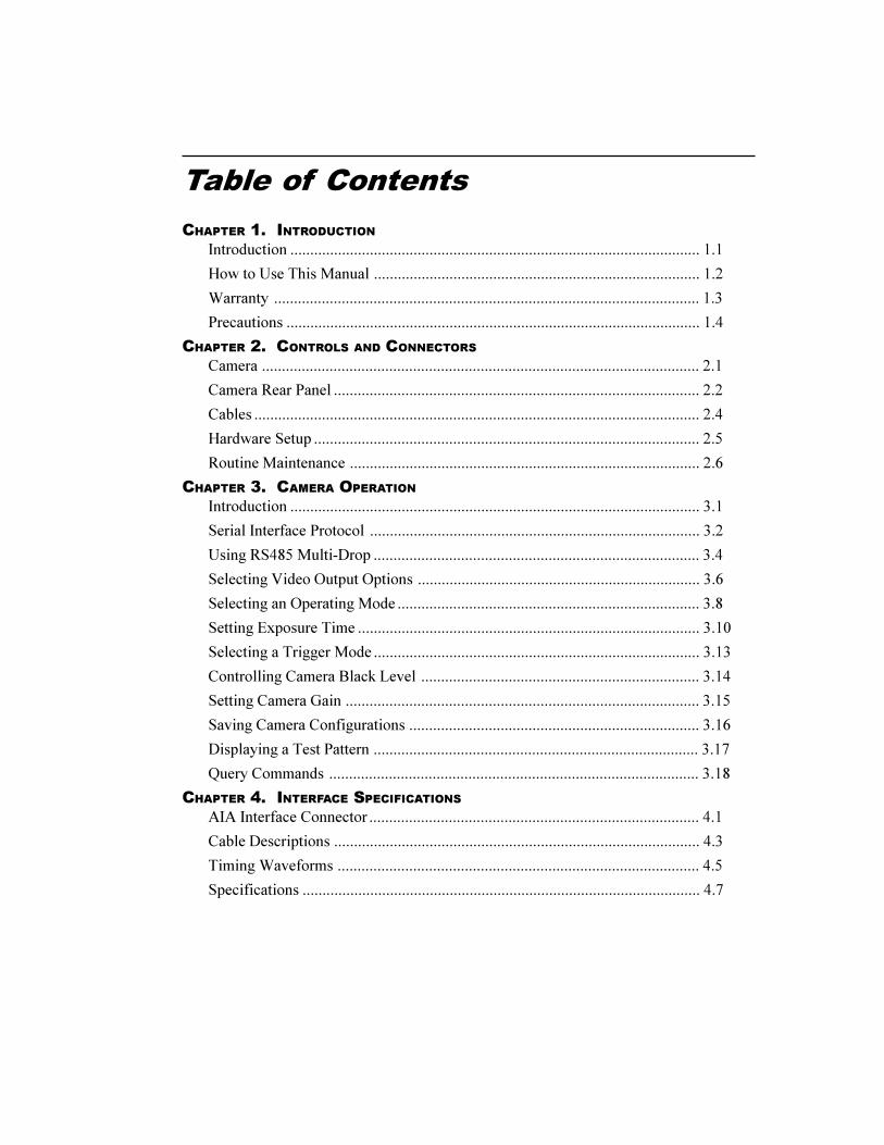
Table of Contents
CHAPTER 1. INTRODUCTION
Introduction ....................................................................................................... 1.1
How to Use This Manual .................................................................................. 1.2
Warranty ........................................................................................................... 1.3
Precautions ........................................................................................................ 1.4
CHAPTER 2. CONTROLS AND CONNECTORS
Camera .............................................................................................................. 2.1
Camera Rear Panel ............................................................................................ 2.2
Cables ................................................................................................................ 2.4
Hardware Setup ................................................................................................. 2.5
Routine Maintenance ........................................................................................ 2.6
CHAPTER 3. CAMERA OPERATION
Introduction ....................................................................................................... 3.1
Serial Interface Protocol ................................................................................... 3.2
Using RS485 Multi-Drop .................................................................................. 3.4
Selecting Video Output Options ....................................................................... 3.6
Selecting an Operating Mode ............................................................................ 3.8
Setting Exposure Time ...................................................................................... 3.10
Selecting a Trigger Mode .................................................................................. 3.13
Controlling Camera Black Level ...................................................................... 3.14
Setting Camera Gain ......................................................................................... 3.15
Saving Camera Configurations ......................................................................... 3.16
Displaying a Test Pattern .................................................................................. 3.17
Query Commands ............................................................................................. 3.18
CHAPTER 4. INTERFACE SPECIFICATIONS
AIA Interface Connector ................................................................................... 4.1
Cable Descriptions ............................................................................................ 4.3
Timing Waveforms ........................................................................................... 4.5
Specifications .................................................................................................... 4.7
Chapter 1. Introduction
Introduction
How to Use This Manual
Warranty
Precautions
1.1
Introduction
INTRODUCTIONThe KODAK MEGAPLUS Camera, Model ES 310 is intended for machinevision, medical imaging, and many other applications. The camera package iscompact and is operated through a connection to a host computer. The AIAinterface connector, located on the camera�s rear panel, sends digital output videoto the computer and receives control commands from the computer.
Featuring an interline Charge Coupled Device (CCD) sensor array, the camera has648(H) x 484 (V) light sensitive elements (pixels). These pixels are 9 micronssquare and have a center to center spacing of 9 microns with a 60 % fill ratio.
The camera operates continuously or in a triggered mode. Exposure times asshort as 94 microseconds are possible with the camera�s electronic shutter andthe frame rate is unaffected by the exposure time in continuous mode. Thecamera has a dual output channel data rate of 20 MHz, with the fastest full framerate being 85 frames per second. Faster frame rates are possible in some operat-ing modes. The camera can be connected to many commercially available framegrabber boards capable of handling eight bits of digital video data, and requiresonly eight watts of power.
1.2
How to Use This Manual
CHAPTER 1. INTRODUCTIONChapter one describes this User�s Manual, a warranty statement and somegeneral precautions to observe when operating this product.
CHAPTER 2. CONTROLS AND CONNECTORSChapter two explains the function of the controls and connectors of theMEGAPLUS Camera.
CHAPTER 3. SETUP AND OPERATIONChapter three contains the commands used to operate the camera. The camera isremotely operated by entering commands into a computer connected to thecamera.
CHAPTER 4. INTERFACE SPECIFICATIONSChapter four details the signals carried by the AIA interface connector includingtiming waveforms.

1.3
Warranty
New Equipment WarrantyKODAK MEGAPLUS Camera
EASTMAN KODAK COMPANY, MOTION ANALYSIS SYSTEMS DIVI-SION, WARRANTS THIS KODAK MEGAPLUS CAMERA AND ACCESSO-RIES MANUFACTURED BY EASTMAN KODAK COMPANY, TO FUNC-TION PROPERLY FOR ONE YEAR FROM THE DATE OF SHIPMENT.
Kodak agrees to perform the following equipment warranty services in theUnited States.
1. Repair service: If shipped to us, repairs will be made at no charge.
2. Parts replacement: Replacement parts installed under warranty will beprovided at no charge.
THIS WARRANTY DOES NOT APPLY UNDER THE FOLLOWING CONDI-TIONS:
� Failure to operate the KODAK MEGAPLUS Camera in accordance withKodak�s written instructions, including environmental specificationslisted in the User�s Manual.
� If there is evidence of the KODAK MEGAPLUS Camera being sub-jected to accidental damage, misuse or abuse.
� If the KODAK MEGAPLUS Camera has been repaired or tampered withby persons other than Kodak personnel, customer personnel trained byKodak or without permission of Kodak.
� Shipping damage is not covered by this warranty. The purchaser has theresponsibility to place a claim of damage in shipment with the carrier.
KODAK MAKES NO OTHER WARRANTIES, EXPRESSED, IMPLIED, OR OF MER-CHANTABILITY FOR THIS EQUIPMENT. IF THIS KODAK MEGAPLUS CAMERADOES NOT FUNCTION PROPERLY DURING THE WARRANTY PERIOD, KODAKWILL REPAIR IT WITHOUT CHARGE ACCORDING TO THE TERMS STATEDABOVE. REPAIR WITHOUT CHARGE IS KODAK�S ONLY OBLIGATION UNDERTHIS WARRANTY. KODAK WILL NOT BE RESPONSIBLE FOR ANY CONSEQUEN-TIAL OR INCIDENTAL DAMAGES RESULTING FROM THE SALE, USE OR IM-PROPER FUNCTIONING OF THIS EQUIPMENT EVEN IF LOSS OR DAMAGE ISCAUSED BY THE NEGLIGENCE OR OTHER FAULT OF KODAK.
KODAK and MEGAPLUS are trademarks.© Copyright Eastman Kodak Company, 1998
1.4
Precautions
FEDERAL COMMUNICATIONS COMMISSION STATEMENTSWARNING: This equipment generates, uses and can radiate radio frequencyenergy, and if not installed and used in accordance with the instruction manual,may cause interference to radio communications. It has been tested and found tocomply with the limits for a Class �A� computing device pursuant to Subpart Bof Part 15 of the FCC Rules and VDE 0871 Class �B�, which are designed toprovide reasonable protection against such interference when operated in acommercial environment. Operation of this equipment in a residential area islikely to cause interference in which case the user at his own expense will berequired to take whatever measures may be required to correct the interference.
This device complies with Part 15 of the FCC Rules and VDE 0871. Operation issubject to the following two conditions: (1) this device may not cause harmfulinterference, and (2) this device must accept any interference received includinginterference that may cause undesired operation.
CAUTIONA laser beam focused on the sensor, either directly or by specular reflection, cancause permanent damage to the sensor. Any laser powerful enough to producelocalized heating at the surface of the sensor will cause damage, even if thecamera power is off. A sensor damaged by laser light is not covered by thewarranty.
OPERATING TEMPERATUREThe KODAK MEGAPLUS Camera is designed to operate satisfactorily in anenvironment where the ambient temperature is between 0 and 40 degrees Centi-grade (32 and 104 degrees Fahrenheit), and there is no water condensationpresent.
STORAGE TEMPERATUREDo not store the equipment in an area where the temperature will drop below -25degrees or exceed 80 degrees Centigrade (-13 to 176 degrees Fahrenheit). Donot allow moisture to condense on the system.
SHIPPINGWhen shipping, use the shipping carton in which the unit was originally deliv-ered. Do not ship the equipment in a cargo area where the temperature will dropbelow -25 degrees or exceed 80 degrees Centigrade (-13 to 176 degrees Fahren-heit). Do not allow moisture to condense on the system.
Chapter 2. Controls and Connectors
Camera
Camera Rear Panel
Cables
Hardware Setup
Routine Maintenance
2.1
Camera
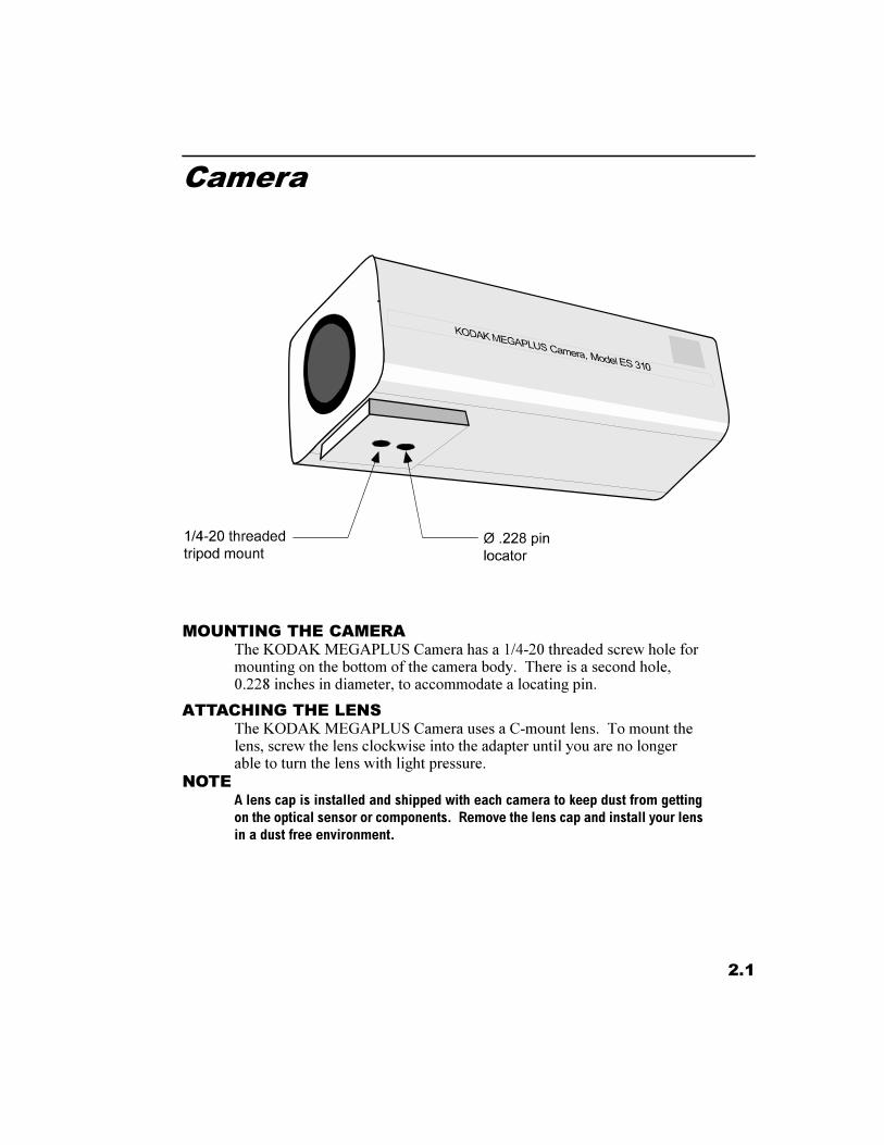
MOUNTING THE CAMERAThe KODAK MEGAPLUS Camera has a 1/4-20 threaded screw hole formounting on the bottom of the camera body. There is a second hole,0.228 inches in diameter, to accommodate a locating pin.
ATTACHING THE LENSThe KODAK MEGAPLUS Camera uses a C-mount lens. To mount thelens, screw the lens clockwise into the adapter until you are no longerable to turn the lens with light pressure.
NOTEA lens cap is installed and shipped with each camera to keep dust from gettingon the optical sensor or components. Remove the lens cap and install your lensin a dust free environment.
2.2
Camera Rear Panel
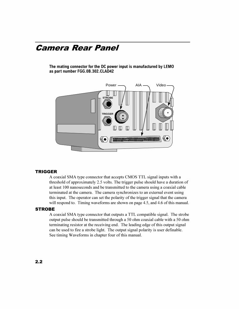
The mating connector for the DC power input is manufactured by LEMOas part number FGG.0B.302.CLAD42
TRIGGERA coaxial SMA type connector that accepts CMOS TTL signal inputs with athreshold of approximately 2.5 volts. The trigger pulse should have a duration ofat least 100 nanoseconds and be transmitted to the camera using a coaxial cableterminated at the camera. The camera synchronizes to an external event usingthis input. The operator can set the polarity of the trigger signal that the camerawill respond to. Timing waveforms are shown on page 4.5, and 4.6 of this manual.
STROBEA coaxial SMA type connector that outputs a TTL compatible signal. The strobeoutput pulse should be transmitted through a 50 ohm coaxial cable with a 50 ohmterminating resistor at the receiving end. The leading edge of this output signalcan be used to fire a strobe light. The output signal polarity is user definable.See timing Waveforms in chapter four of this manual.
TRIGGER
STROBE
AIA VideoPower
2.3
Camera Rear Panel
DC POWER INPUTThis two pin connector is the power input for the camera. The powersupply voltage should be between 12 and 28 volts DC measured at theconnector on the camera rear panel. The current draw is a maximum of0.8 amps at the lowest input supply voltage and 0.3 amps at the highestinput supply voltage.
WARNINGReversing the polarity of the DC voltage input or voltage levels in excess of 30volts may permanently damage the camera.
AIA INTERFACEThis is a 68 pin, high density, dual row, D type connector that connectsthe camera to a frame grabber board and a serial communication inter-face for camera control. The frame grabber board processes and displaysdigital 0video from the camera. A complete technical description of theconnector and the signals that it carries is contained in chapter four ofthis manual.
VIDEO OUTPUTA BNC type connector provides a 1 volt peak to peak video signal output. Thisoutput is intended to drive a coaxial cable terminated in 75 ohm to ground at thereceiving end. The video output can be user configured for CCIR or RS170video standards. See the VFR command on page 3.6 of this manual.
2.4
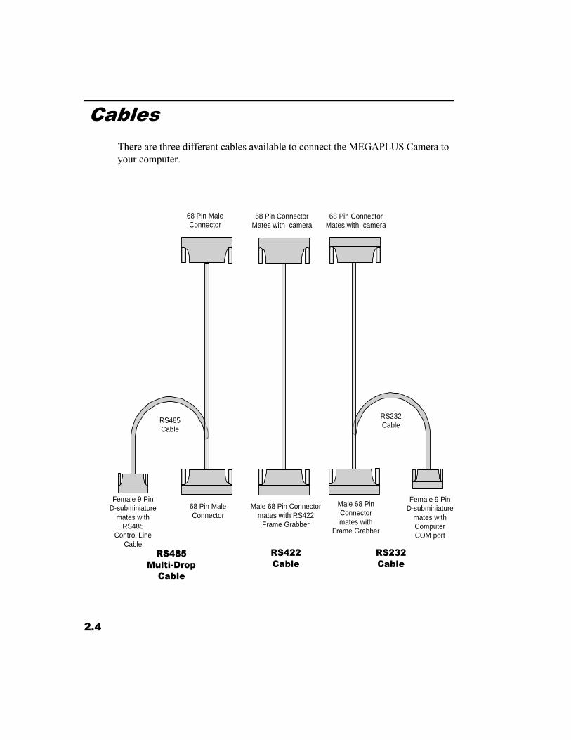
Cables
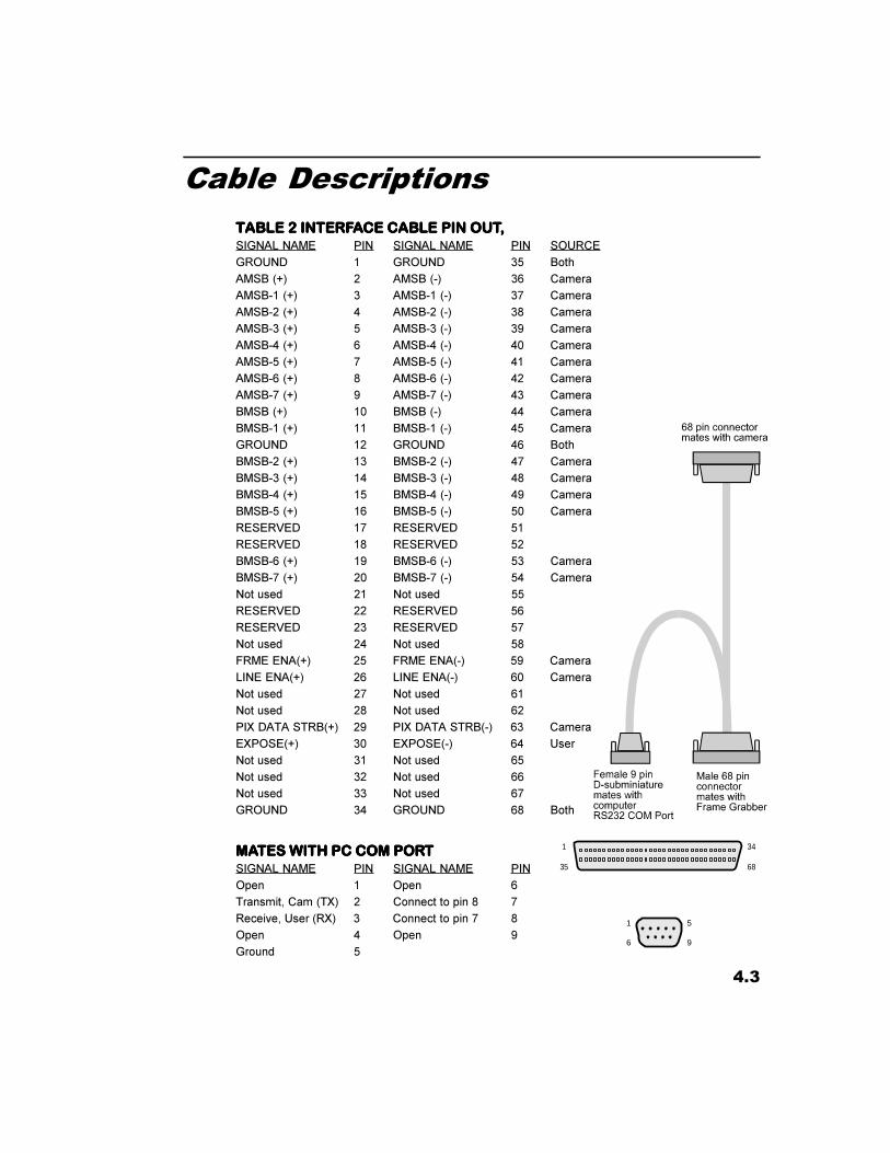
There are three different cables available to connect the MEGAPLUS Camera toyour computer.
68 Pin ConnectorMates with camera
Male 68 PinConnectormates with
Frame Grabber
Female 9 PinD-subminiature
mates withComputerCOM port
RS232Cable
68 Pin ConnectorMates with camera
Male 68 Pin Connectormates with RS422
Frame Grabber
56���0XOWL�'URS
&DEOH
68 Pin MaleConnector
68 Pin MaleConnector
Female 9 PinD-subminiature
mates withRS485
Control LineCable
RS485Cable
56���&DEOH
56���&DEOH
2.5
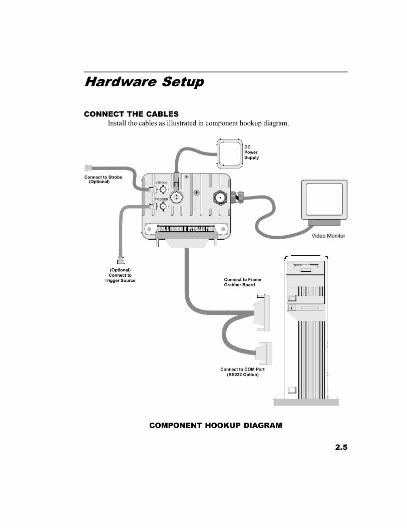
Hardware Setup
CONNECT THE CABLESInstall the cables as illustrated in component hookup diagram.
COMPONENT HOOKUP DIAGRAM
2.6
Routine Maintenance
There are no user serviceable parts in the camera. The camera must be returnedto the factory for repair if a malfunction occurs.
The lens and the sensor cover glass should be cleaned using dust free compressed air.
Clean the exterior of the camera with a soft dry cloth. You may dampen a softcloth with a mild soap solution for stubborn dirt.
Chapter 3. Camera Operation
Introduction
Serial Interface Protocol
Using RS485 Multi-Drop
Selecting Video Output Options
Selecting an Operating Mode
Setting Exposure Time
Selecting a Trigger Mode
Controlling Camera Black Level
Setting Camera Gain
Saving Camera Configurations
Displaying a Test Pattern
Query Commands
3.1
Introduction
The KODAK MEGAPLUS Camera, Model ES 310, does not have any manualcontrols. Camera operation is accomplished by commands sent to the camerathrough a serial data link from a personal computer. In this chapter we willpresent the various operating modes of the camera with an explanation of thefunction followed by the command sequence that must be transmitted by thecomputer. The camera serial data link is configurable as RS232 or RS422/RS485. The command syntax is the same in either case.
A list of the camera functions, their commands, and the page where an explana-tion of each function can be found follows:
Function Command PageSet Communications Port ..............................SCP ........................................... 3.3RS485 Multi-Drop Address Set ....................ADR ......................................... 3.4RS485 Multi-Drop Select ..............................MDD ........................................ 3.5RS485 Multi-Drop, Log Camera ..................LOG ......................................... 3.5Analog Video Output ....................................VID........................................... 3.6Analog Video Output Format .......................VFR .......................................... 3.6Alternate Row Select ....................................ALT .......................................... 3.6Block Readout Mode ....................................BLK .......................................... 3.7Block Start .....................................................BST .......................................... 3.7Block End ......................................................BSP ........................................... 3.7Mode .............................................................MDE ......................................... 3.9Frame Rate Select .........................................FRS ........................................... 3.9Exposure ........................................................EXE .......................................... 3.10Auto Expose Select .......................................AEX ......................................... 3.10Auto Expose Video Level .............................SET ........................................... 3.10Auto Expose Vertical Address ......................AXX ......................................... 3.11Auto Expose Horizontal Address ..................AXY ......................................... 3.12Trigger ...........................................................TRS, TRM, TRE ...................... 3.13Black Level ...................................................BKE .......................................... 3.14Black Level Balance .....................................BKB ......................................... 3.14Digital Gain ...................................................DGN ......................................... 3.15Gain Balance .................................................GAB ......................................... 3.15Strobe Polarity ...............................................STP ........................................... 3.15Restore Factory Settings ...............................RFS ........................................... 3.16Save ...............................................................SAV .......................................... 3.16Reset ..............................................................RST .......................................... 3.16Display Wedge ..............................................WDG ........................................ 3.17Status Query ..................................................STS ........................................... 3.18Identification Query ...................................... IDN........................................... 3.18
3.2
Serial Interface Protocol
SERIAL COMMUNICATIONS PROTOCOLThe camera uses a full duplex UART type asynchronous system, using standardnonreturn-to-zero (NRZ) format (one start bit, eight data bits, one stop bit, noparity). The baud rate is fixed at 9600. The character code is based on theASCII standard.
The character flow control protocol is XON/XOFF. XON is assigned DC1(control-Q) and XOFF is assigned DC3 (control-S). The receiver sends theXOFF character when it wants the sender to pause in sending data and an XONcharacter when it wants the sender to resume.
The camera will recognize a command as three command characters, followed bya space character, followed by an argument that consists of one or more charac-ters, ended by the carriage return and line feed characters. The camera respondsto a valid command with a carriage return and line feed (CR-LF)
The camera will recognize a query as three command characters followed by thequestion mark character, then ended by the carriage return character.
The camera responds to a query with three command characters, followed by aspace bar character, followed by an argument that consists of one or morecharacters, then ended by carriage return and line feed (CR-LF).
ERROR MESSAGESThe camera can respond to an erroneous command or query in one of fourpossible ways.
Message from camera Explanation
ERROR-SYNTAX The camera cannot make sense of the command.
ERROR-ARG RANGE The command is recognized but the argument is outof range or indecipherable.
ERROR-TRANSMISSION The receiver detected a transmission error such asbuffer overflow, parity, or framing.
ERROR-MULTIDROP The command was recognized but conflicts withCONFIGURATION current multidrop settings
NOTEIn the following text the command and argument that are sent to the camera arein bold type. The carriage return and line feed at the end of each command arenot shown as they are required in every instance.
3.3
Serial Interface Protocol
SETTING SERIAL COMMUNICATIONS MODEThe camera can use either an RS232 or an RS422/RS485 connection for serialcommunication, but your host computer must have both RS232 and RS422/RS485 communications capability to use this command.
Type In: Response Explanation
SCP 232 CR-LF Sets the camera serial port to respond to RS232 signals.
SCP 422 CR-LF Sets the camera serial port to respond to RS422 signals.SCP? Queries the COM port setting.
SCP x Means the COM mode is set to x.
NOTERS422 and RS485 signal levels and connections are the same. Only two devicescan communicate using RS422 electronic driver circuits. Multiple devices canbe connected together using RS485 electronic driver circuits, as illustrated byMulti-Drop on the next pages.
ProcedureAssuming you are using an RS232 connection, type in SCP 422. With power stillapplied to the camera, disconnect the RS232 cable and substitute an RS422/RS485connection. Type in SAV to lock in the RS422 option. The camera ignores theSCP command if power is turned off before the SAV command is entered.
3.4
Using RS485 Multi-DropRS485 MULTI-DROP, ADDRESS SET
This command is invalid when multi-drop mode is on (see below). Assign anaddress to a camera with this command and then execute a SAV command (page3.15). The camera�s address will default to zero when it�s power is turned off ifyou do not issue a save command after changing a camera�s address. Theaddress is used to send a camera commands when in RS485 multi-drop mode.
Type In: Response Explanation
ADR x CR-LF Where x must be a unique address for each cameraconnected to your RS485 network. An address mustbe an integer between 0 and 99. Cameras are shippedfrom the factory with their address set to 0.
ADR? Queries a camera for its address setting.
ADR x Means the camera address is set to x.
RS485 MULTI-DROP SELECTUse this command to turn the multi-drop mode on or off. This command should beused when you are connected to only one camera, at the same time you assign acamera its address, for example. This command is not valid if you are using anRS232 communications link. When multi-drop mode is on, all cameras connectedto the RS485 communications link listen for commands, however only the cameraaddressed by the last LOG command will respond to commands.
Type In: Response Explanation
MDD OF CR-LF Turns multi-drop mode off.
MDD ON CR-LF Turns multi-drop mode on.
MDD? Queries the multi-drop mode setting.
MDD x Multi-Drop is set to x
LOG CAMERA RS485 MULTI-DROP
The log command instructs a specific camera to respond to subsequent com-mands. The camera addressed with the LOG command is the only camera thatwill respond to serial commands until you use the LOG command to addressanother camera. This command is invalid when multi-drop mode is off.
Type In: Response Explanation
LOG x CR-LF Where x is the address of the camera that you wantto respond to all subsequent commands. The ad-dress range is from 0 to 99.
Use the ADR? command to get the address of thecurrently logged camera.
3.5
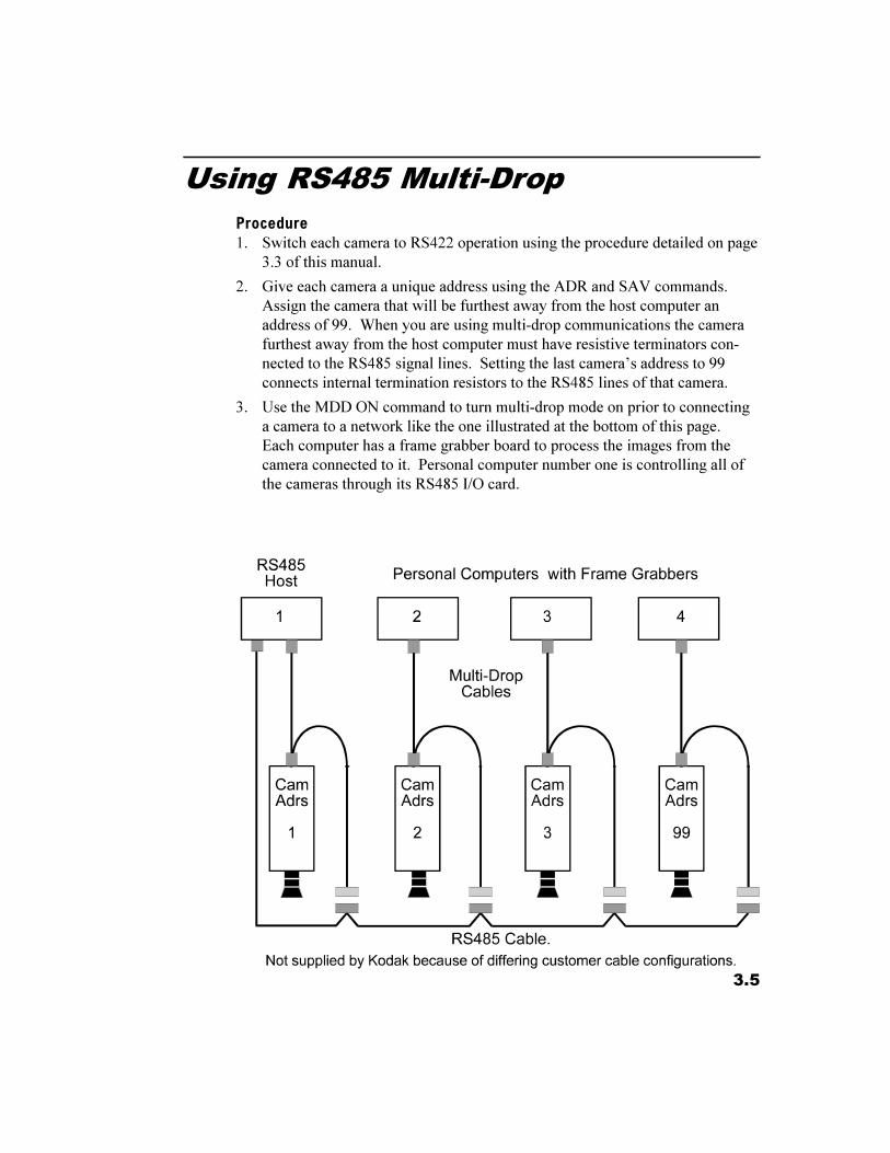
Using RS485 Multi-DropProcedure1. Switch each camera to RS422 operation using the procedure detailed on page
3.3 of this manual.
2. Give each camera a unique address using the ADR and SAV commands.Assign the camera that will be furthest away from the host computer anaddress of 99. When you are using multi-drop communications the camerafurthest away from the host computer must have resistive terminators con-nected to the RS485 signal lines. Setting the last camera�s address to 99connects internal termination resistors to the RS485 lines of that camera.
3. Use the MDD ON command to turn multi-drop mode on prior to connectinga camera to a network like the one illustrated at the bottom of this page.Each computer has a frame grabber board to process the images from thecamera connected to it. Personal computer number one is controlling all ofthe cameras through its RS485 I/O card.
3.6
Selecting Video Output Options
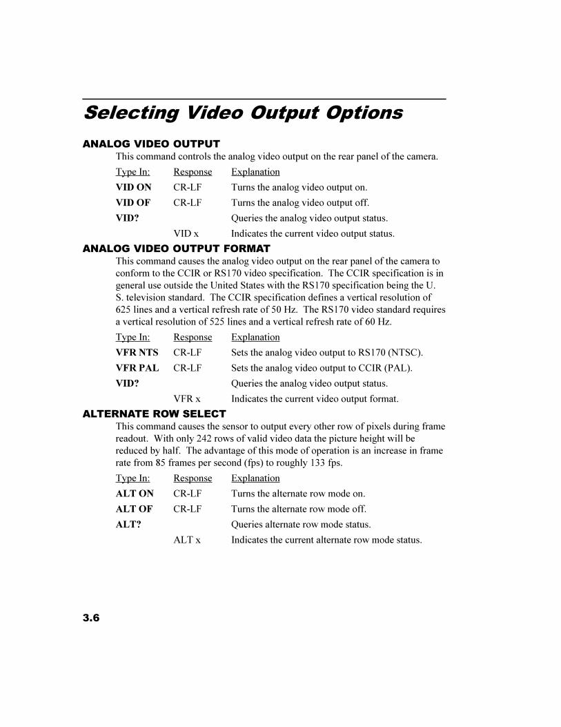
ANALOG VIDEO OUTPUTThis command controls the analog video output on the rear panel of the camera.
Type In: Response Explanation
VID ON CR-LF Turns the analog video output on.
VID OF CR-LF Turns the analog video output off.
VID? Queries the analog video output status.
VID x Indicates the current video output status.
ANALOG VIDEO OUTPUT FORMATThis command causes the analog video output on the rear panel of the camera toconform to the CCIR or RS170 video specification. The CCIR specification is ingeneral use outside the United States with the RS170 specification being the U.S. television standard. The CCIR specification defines a vertical resolution of625 lines and a vertical refresh rate of 50 Hz. The RS170 video standard requiresa vertical resolution of 525 lines and a vertical refresh rate of 60 Hz.
Type In: Response Explanation
VFR NTS CR-LF Sets the analog video output to RS170 (NTSC).
VFR PAL CR-LF Sets the analog video output to CCIR (PAL).
VID? Queries the analog video output status.
VFR x Indicates the current video output format.
ALTERNATE ROW SELECTThis command causes the sensor to output every other row of pixels during framereadout. With only 242 rows of valid video data the picture height will bereduced by half. The advantage of this mode of operation is an increase in framerate from 85 frames per second (fps) to roughly 133 fps.
Type In: Response Explanation
ALT ON CR-LF Turns the alternate row mode on.
ALT OF CR-LF Turns the alternate row mode off.
ALT? Queries alternate row mode status.
ALT x Indicates the current alternate row mode status.
3.7
Selecting Video Output Options
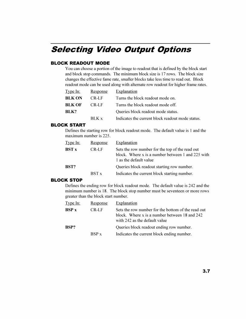
BLOCK READOUT MODEYou can choose a portion of the image to readout that is defined by the block startand block stop commands. The minimum block size is 17 rows. The block sizechanges the effective fame rate, smaller blocks take less time to read out. Blockreadout mode can be used along with alternate row readout for higher frame rates.
Type In: Response Explanation
BLK ON CR-LF Turns the block readout mode on.
BLK OF CR-LF Turns the block readout mode off.
BLK? Queries block readout mode status.
BLK x Indicates the current block readout mode status.
BLOCK STARTDefines the starting row for block readout mode. The default value is 1 and themaximum number is 225.
Type In: Response Explanation
BST x CR-LF Sets the row number for the top of the read outblock. Where x is a number between 1 and 225 with1 as the default value
BST? Queries block readout starting row number.
BST x Indicates the current block starting number.
BLOCK STOPDefines the ending row for block readout mode. The default value is 242 and theminimum number is 18. The block stop number must be seventeen or more rowsgreater than the block start number.
Type In: Response Explanation
BSP x CR-LF Sets the row number for the bottom of the read outblock. Where x is a number between 18 and 242with 242 as the default value
BSP? Queries block readout ending row number.
BSP x Indicates the current block ending number.
3.8
Selecting an Operating Mode
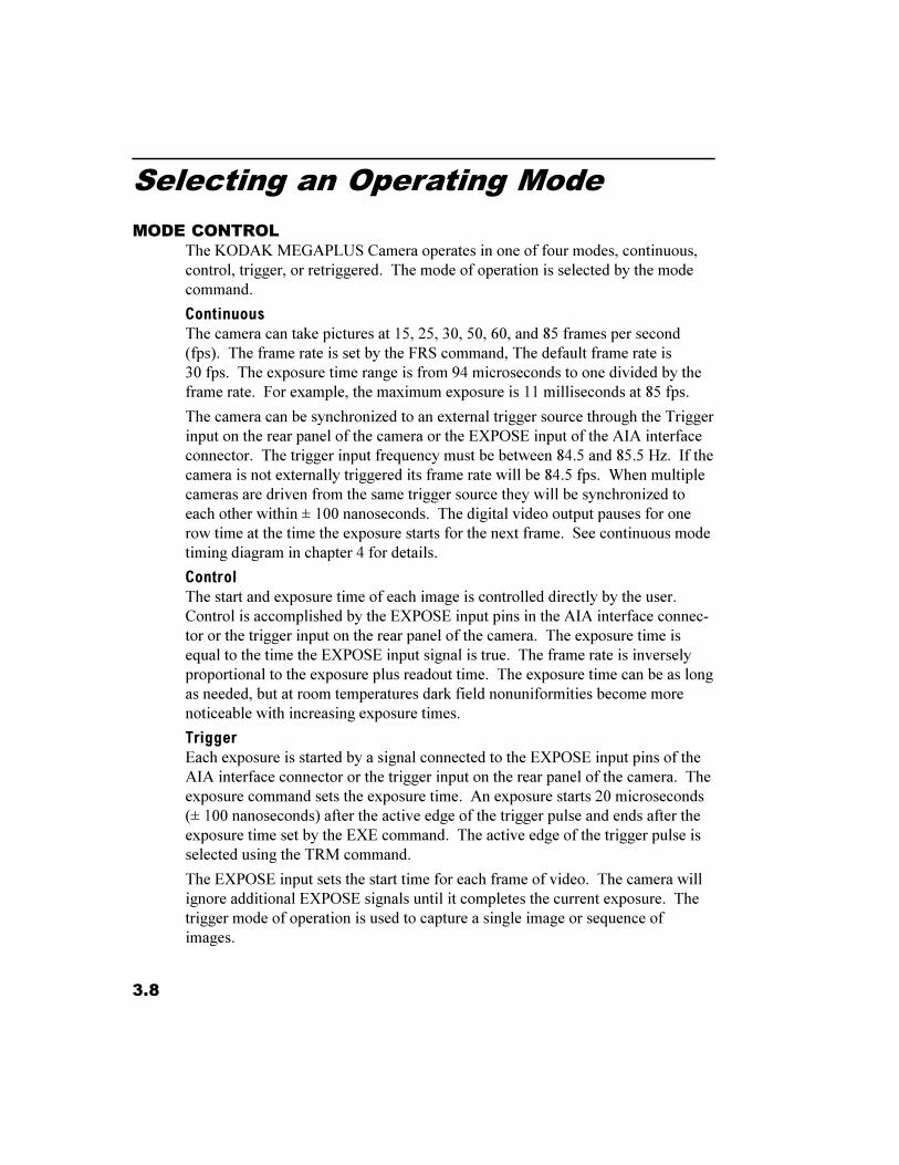
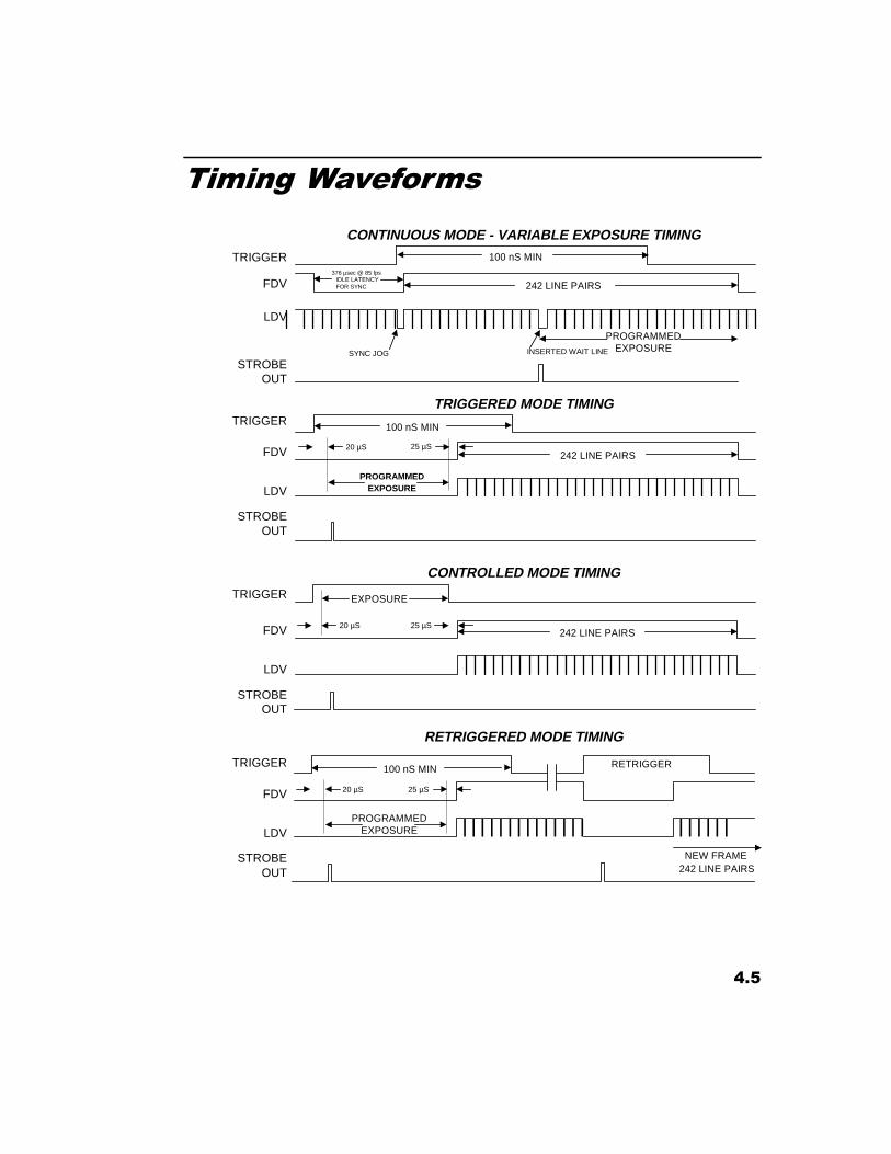
MODE CONTROLThe KODAK MEGAPLUS Camera operates in one of four modes, continuous,control, trigger, or retriggered. The mode of operation is selected by the modecommand.
ContinuousThe camera can take pictures at 15, 25, 30, 50, 60, and 85 frames per second(fps). The frame rate is set by the FRS command, The default frame rate is30 fps. The exposure time range is from 94 microseconds to one divided by theframe rate. For example, the maximum exposure is 11 milliseconds at 85 fps.
The camera can be synchronized to an external trigger source through the Triggerinput on the rear panel of the camera or the EXPOSE input of the AIA interfaceconnector. The trigger input frequency must be between 84.5 and 85.5 Hz. If thecamera is not externally triggered its frame rate will be 84.5 fps. When multiplecameras are driven from the same trigger source they will be synchronized toeach other within ± 100 nanoseconds. The digital video output pauses for onerow time at the time the exposure starts for the next frame. See continuous modetiming diagram in chapter 4 for details.
ControlThe start and exposure time of each image is controlled directly by the user.Control is accomplished by the EXPOSE input pins in the AIA interface connec-tor or the trigger input on the rear panel of the camera. The exposure time isequal to the time the EXPOSE input signal is true. The frame rate is inverselyproportional to the exposure plus readout time. The exposure time can be as longas needed, but at room temperatures dark field nonuniformities become morenoticeable with increasing exposure times.
TriggerEach exposure is started by a signal connected to the EXPOSE input pins of theAIA interface connector or the trigger input on the rear panel of the camera. Theexposure command sets the exposure time. An exposure starts 20 microseconds(± 100 nanoseconds) after the active edge of the trigger pulse and ends after theexposure time set by the EXE command. The active edge of the trigger pulse isselected using the TRM command.
The EXPOSE input sets the start time for each frame of video. The camera willignore additional EXPOSE signals until it completes the current exposure. Thetrigger mode of operation is used to capture a single image or sequence ofimages.
3.9
Selecting an Operating Mode
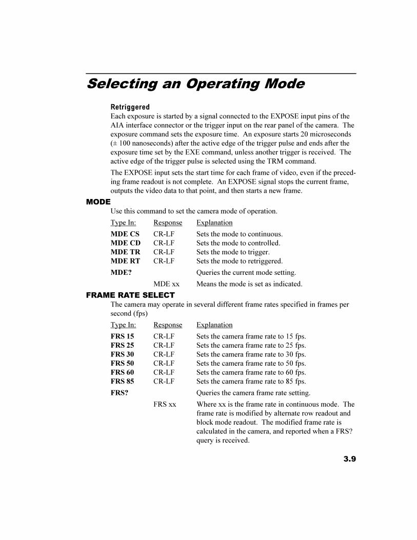
RetriggeredEach exposure is started by a signal connected to the EXPOSE input pins of theAIA interface connector or the trigger input on the rear panel of the camera. Theexposure command sets the exposure time. An exposure starts 20 microseconds(± 100 nanoseconds) after the active edge of the trigger pulse and ends after theexposure time set by the EXE command, unless another trigger is received. Theactive edge of the trigger pulse is selected using the TRM command.
The EXPOSE input sets the start time for each frame of video, even if the preced-ing frame readout is not complete. An EXPOSE signal stops the current frame,outputs the video data to that point, and then starts a new frame.
MODEUse this command to set the camera mode of operation.
Type In: Response Explanation
MDE CS CR-LF Sets the mode to continuous.MDE CD CR-LF Sets the mode to controlled.MDE TR CR-LF Sets the mode to trigger.MDE RT CR-LF Sets the mode to retriggered.
MDE? Queries the current mode setting.
MDE xx Means the mode is set as indicated.
FRAME RATE SELECTThe camera may operate in several different frame rates specified in frames persecond (fps)
Type In: Response Explanation
FRS 15 CR-LF Sets the camera frame rate to 15 fps.FRS 25 CR-LF Sets the camera frame rate to 25 fps.FRS 30 CR-LF Sets the camera frame rate to 30 fps.FRS 50 CR-LF Sets the camera frame rate to 50 fps.FRS 60 CR-LF Sets the camera frame rate to 60 fps.FRS 85 CR-LF Sets the camera frame rate to 85 fps.
FRS? Queries the camera frame rate setting.
FRS xx Where xx is the frame rate in continuous mode. Theframe rate is modified by alternate row readout andblock mode readout. The modified frame rate iscalculated in the camera, and reported when a FRS?query is received.
3.10
Setting Exposure Time
EXPOSUREThis command sets the camera exposure time. Enter an exposure time valuebetween 94 microseconds, and about (1/frame rate), in milliseconds, when youare in continuous mode. The maximum exposure time is 96 milliseconds intrigger and retrigger modes. The camera picks a valid exposure time closest tothe value you entered. The exposure time setting is not valid in control mode.The exposure time range is affected by the alternate row and block mode settings.
Type In Response Explanation
EXE xx.xxx CR-LF Sets the exposure time in milliseconds
EXE? Queries the current exposure setting.
EXE xx.xxx Where xx.xxx is the exposure time expressed inmilliseconds.
AUTO EXPOSE SELECTThe camera adjusts its exposure time to hold a user set video level as sceneillumination changes. The camera takes a digital video sample within an expo-sure window. The exposure window is a 128 pixels wide by 256 rows high. Theuser can set the location of the exposure window or accept the default locationnear the center of the image. The average amplitude of the video in the exposurewindow is then used to control the exposure time.
Type In Response Explanation
AEX ON CR-LF Turns auto expose on, holding the video in theexposure window to the value selected by the SETcommand.
AEX OF CR-LF Turns auto expose off.
AEX CAL CR-LF The camera checks the video level within the expo-sure window, and then turns on the auto exposurefunction to maintain that video level, rather thanusing the level selected by the SET command.
AEX? Queries the auto expose status.
AEX x Means that auto expose is set to x.
NOTEWhen you are using alternate row and/or block readout modes avoid having blackpixels fall inside the exposure window. Black areas inside the exposure windowwill cause errors in the auto exposure process. Adjust the block start and stopvalues or the exposure window position so that only valid video data is sampledfor the auto exposure function.
3.11
Setting Exposure Time
AUTO EXPOSE VIDEO LEVELSets the target video level for the auto expose function. Video level ranges from0 at black to 127 for white.
Type In: Response Explanation
SET xxx CR-LF Sets the target video level to xxx with a rangebetween 0 and 127.
SET? Queries the camera for the current target video level.
SET xxx Means that the target video level is set as indicated.
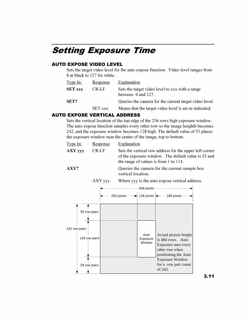
AUTO EXPOSE VERTICAL ADDRESSSets the vertical location of the top edge of the 256 rows high exposure window.The auto expose function samples every other row so the image heighth becomes242, and the exposure window becomes 128 high. The default value of 55 placesthe exposure window near the center of the image, top to bottom.
Type In: Response Explanation
AXY yyy CR-LF Sets the vertical row address for the upper left cornerof the exposure window. The default value is 55 andthe range of values is from 1 to 114.
AXY? Queries the camera for the current sample boxvertical location.
AXY yyy Where yyy is the auto expose vertical address.
AutoExposureWindow
55 row pairs
128 row pairs
59 row pairs
242 row pairs
Actual picture heightis 484 rows. AutoExposure uses everyother row whenpositioning the AutoExposure Windowfor a row pair countof 242.
255 pixels 128 pixels 265 pixels
648 pixels
3.12
Setting Exposure Time
AUTO EXPOSE HORIZONTAL ADDRESSSets the horizontal location of the left hand edge of the 128 pixel wide exposurewindow. The default value of 255 puts the exposure window near the center ofthe image, left to right.
Type In: Response Explanation
AXX xxx CR-LF Sets the horizontal pixel address for the upper leftcorner of the exposure window. The default value is255 and the range of values is from 1 to 517.
AXX? Queries the camera for the current sample boxhorizontal location.
AXX xxx Where xxx is the auto expose horizontal address.
3.13
Selecting a Trigger Mode
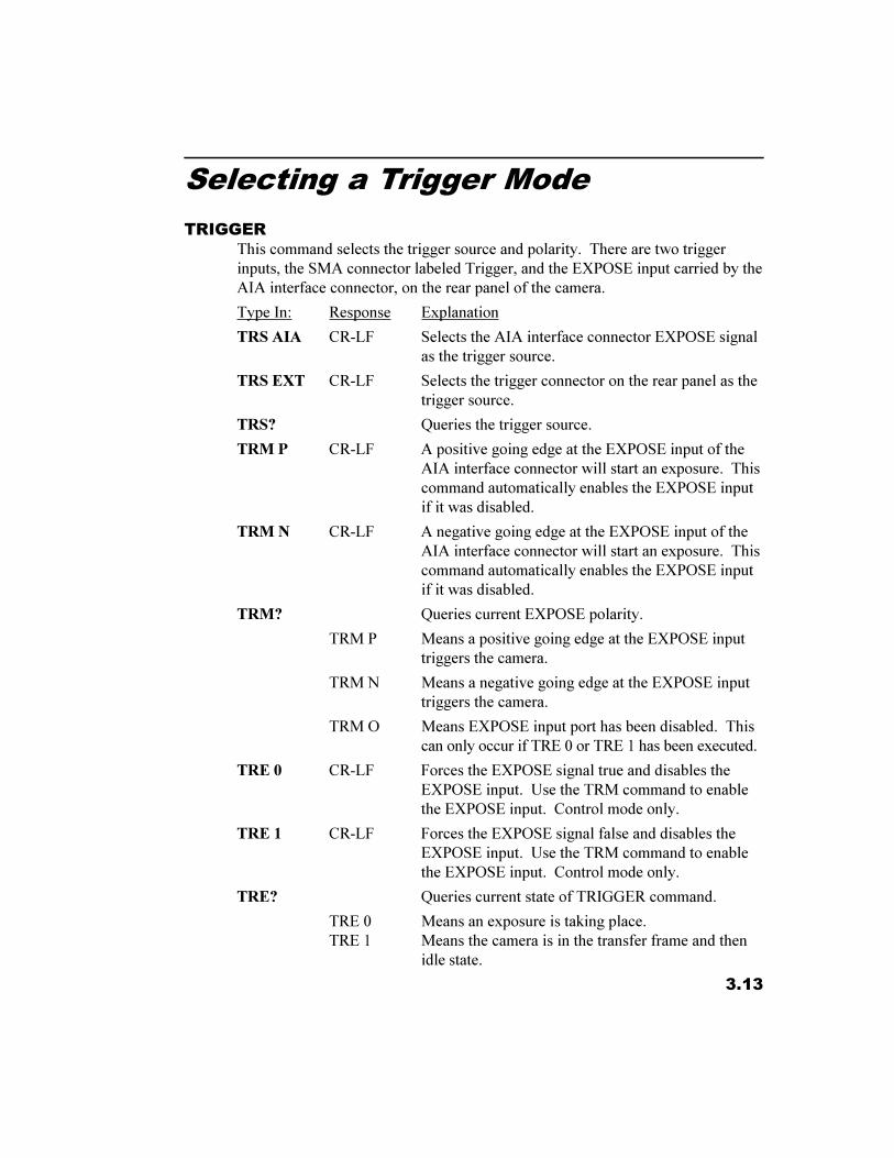
TRIGGERThis command selects the trigger source and polarity. There are two triggerinputs, the SMA connector labeled Trigger, and the EXPOSE input carried by theAIA interface connector, on the rear panel of the camera.
Type In: Response Explanation
TRS AIA CR-LF Selects the AIA interface connector EXPOSE signalas the trigger source.
TRS EXT CR-LF Selects the trigger connector on the rear panel as thetrigger source.
TRS? Queries the trigger source.
TRM P CR-LF A positive going edge at the EXPOSE input of theAIA interface connector will start an exposure. Thiscommand automatically enables the EXPOSE inputif it was disabled.
TRM N CR-LF A negative going edge at the EXPOSE input of theAIA interface connector will start an exposure. Thiscommand automatically enables the EXPOSE inputif it was disabled.
TRM? Queries current EXPOSE polarity.
TRM P Means a positive going edge at the EXPOSE inputtriggers the camera.
TRM N Means a negative going edge at the EXPOSE inputtriggers the camera.
TRM O Means EXPOSE input port has been disabled. Thiscan only occur if TRE 0 or TRE 1 has been executed.
TRE 0 CR-LF Forces the EXPOSE signal true and disables theEXPOSE input. Use the TRM command to enablethe EXPOSE input. Control mode only.
TRE 1 CR-LF Forces the EXPOSE signal false and disables theEXPOSE input. Use the TRM command to enablethe EXPOSE input. Control mode only.
TRE? Queries current state of TRIGGER command.
TRE 0 Means an exposure is taking place.TRE 1 Means the camera is in the transfer frame and then
idle state.
3.14
Controlling Camera Black Level
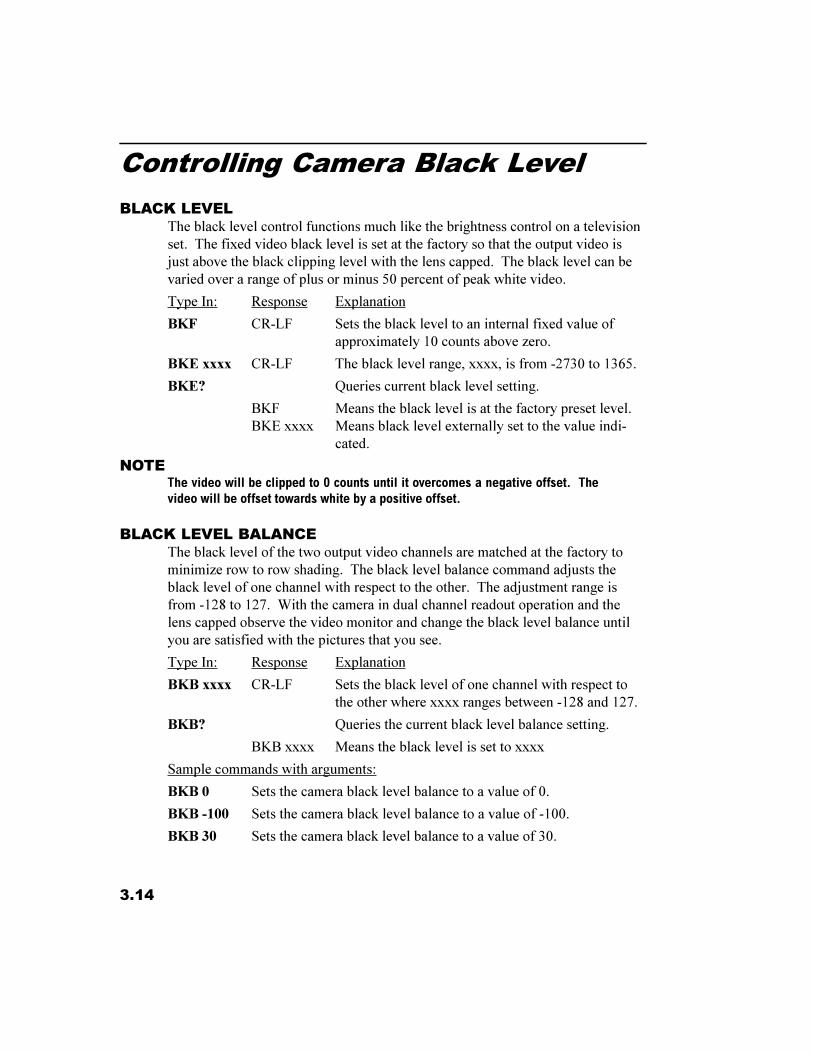
BLACK LEVELThe black level control functions much like the brightness control on a televisionset. The fixed video black level is set at the factory so that the output video isjust above the black clipping level with the lens capped. The black level can bevaried over a range of plus or minus 50 percent of peak white video.
Type In: Response Explanation
BKF CR-LF Sets the black level to an internal fixed value ofapproximately 10 counts above zero.
BKE xxxx CR-LF The black level range, xxxx, is from -2730 to 1365.
BKE? Queries current black level setting.
BKF Means the black level is at the factory preset level.BKE xxxx Means black level externally set to the value indi-
cated.
NOTEThe video will be clipped to 0 counts until it overcomes a negative offset. Thevideo will be offset towards white by a positive offset.
BLACK LEVEL BALANCEThe black level of the two output video channels are matched at the factory tominimize row to row shading. The black level balance command adjusts theblack level of one channel with respect to the other. The adjustment range isfrom -128 to 127. With the camera in dual channel readout operation and thelens capped observe the video monitor and change the black level balance untilyou are satisfied with the pictures that you see.
Type In: Response Explanation
BKB xxxx CR-LF Sets the black level of one channel with respect tothe other where xxxx ranges between -128 and 127.
BKB? Queries the current black level balance setting.
BKB xxxx Means the black level is set to xxxx
Sample commands with arguments:
BKB 0 Sets the camera black level balance to a value of 0.
BKB -100 Sets the camera black level balance to a value of -100.
BKB 30 Sets the camera black level balance to a value of 30.
3.15
Setting Camera Gain
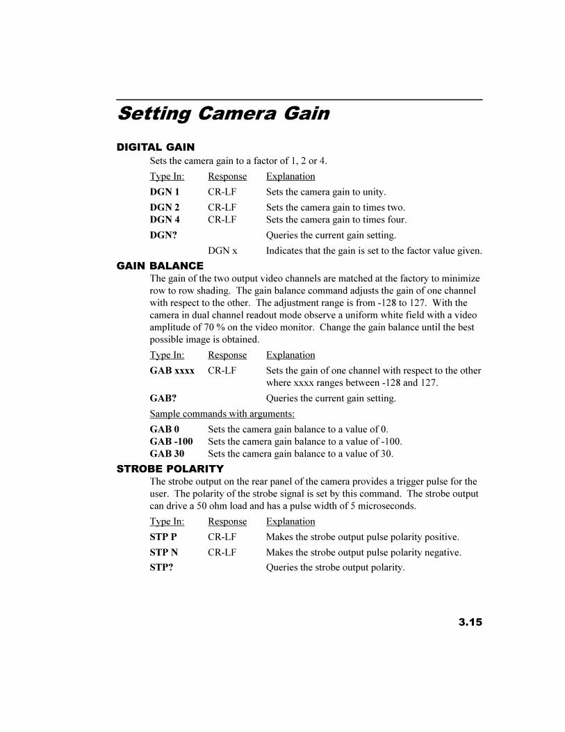
DIGITAL GAINSets the camera gain to a factor of 1, 2 or 4.
Type In: Response Explanation
DGN 1 CR-LF Sets the camera gain to unity.
DGN 2 CR-LF Sets the camera gain to times two.DGN 4 CR-LF Sets the camera gain to times four.
DGN? Queries the current gain setting.
DGN x Indicates that the gain is set to the factor value given.
GAIN BALANCEThe gain of the two output video channels are matched at the factory to minimizerow to row shading. The gain balance command adjusts the gain of one channelwith respect to the other. The adjustment range is from -128 to 127. With thecamera in dual channel readout mode observe a uniform white field with a videoamplitude of 70 % on the video monitor. Change the gain balance until the bestpossible image is obtained.
Type In: Response Explanation
GAB xxxx CR-LF Sets the gain of one channel with respect to the otherwhere xxxx ranges between -128 and 127.
GAB? Queries the current gain setting.
Sample commands with arguments:
GAB 0 Sets the camera gain balance to a value of 0.GAB -100 Sets the camera gain balance to a value of -100.GAB 30 Sets the camera gain balance to a value of 30.
STROBE POLARITYThe strobe output on the rear panel of the camera provides a trigger pulse for theuser. The polarity of the strobe signal is set by this command. The strobe outputcan drive a 50 ohm load and has a pulse width of 5 microseconds.
Type In: Response Explanation
STP P CR-LF Makes the strobe output pulse polarity positive.
STP N CR-LF Makes the strobe output pulse polarity negative.
STP? Queries the strobe output polarity.
3.16
Saving Camera Configurations
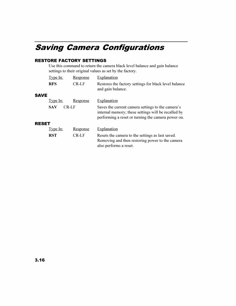
RESTORE FACTORY SETTINGSUse this command to return the camera black level balance and gain balancesettings to their original values as set by the factory.
Type In: Response Explanation
RFS CR-LF Restores the factory settings for black level balanceand gain balance.
SAVEType In: Response Explanation
SAV CR-LF Saves the current camera settings to the camera�sinternal memory; these settings will be recalled byperforming a reset or turning the camera power on.
RESETType In: Response Explanation
RST CR-LF Resets the camera to the settings as last saved.Removing and then restoring power to the cameraalso performs a reset.
3.17
Displaying a Test Pattern
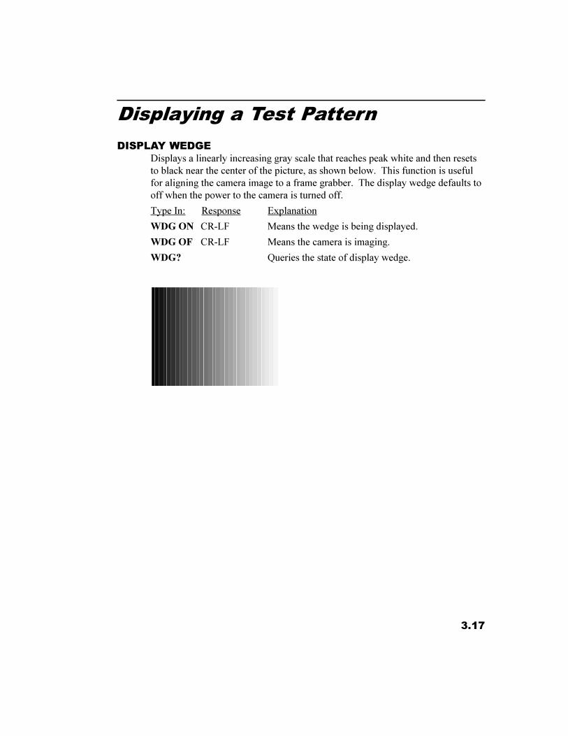
DISPLAY WEDGEDisplays a linearly increasing gray scale that reaches peak white and then resetsto black near the center of the picture, as shown below. This function is usefulfor aligning the camera image to a frame grabber. The display wedge defaults tooff when the power to the camera is turned off.
Type In: Response Explanation
WDG ON CR-LF Means the wedge is being displayed.
WDG OF CR-LF Means the camera is imaging.
WDG? Queries the state of display wedge.
3.18
Query Commands
STATUS QUERYThe status query command enables the user to get all the camera operatingparameter information with a single command.
Type In: Response Explanation
STS? Gives complete camera status with one query. Thefollowing parameters are transmitted with a carriagereturn after each parameter:
Response Definition Example
GAB xxxx .. Shows the gain balance setting. ...................................GAB 36BKB xxxx .. Shows the black level balance setting. ........................BKB 100BKE xxxx ... Shows black level setting. ...........................................BKE 58MDE xx ...... Shows the operating mode. .........................................MDE CSEXE xx ....... Shows the exposure time .............................................EXE 58STP x .......... Show the strobe pulse polarity ....................................STP PTRM x ........ Shows the trigger logic polarity. .................................TRM PTRS xxx ..... Selects the trigger source .............................................TRS AIATRE x ......... Shows the exposure state. ............................................TRE 1DGN x ........ Shows the digital gain setting. .....................................DGN 1AEX xx ...... Shows the auto exposure setting. ................................AEX ONAXX x ........ Shows the auto exposure horizontal address. ..............AXX 260AXY x ........ Shows the auto exposure vertical address. ..................AXY 89BLK xx ....... Shows the block select setting. ....................................BLK ONBST x ......... Shows the block start address. .....................................BST 1BSP x .......... Shows the block stop address. .....................................BSP 242ALT x ......... Shows alternate row select setting. ..............................ALT OFMDD x ....... Shows the multi-drop select setting. ............................MDD OFADR x ........ Shows the camera multi-drop address. ........................ADR 1SET xx ........ Shows the auto exposure reference level. ...................SET 64SCP xxx...... Sets the communications port protocol .......................SCP 232
IDENTIFICATION QUERYType In: Response
IDN ? KODAK MEGAPLUS Camera Model ES 310,V1.00
Explanation
Queries the camera for model number and software version.
Chapter 4. Interface Specifications
AIA Interface Connector
Cable Descriptions
Timing Waveforms
Specifications
4.1
AIA Interface Connector
INTRODUCTIONChapter four gives you the information needed to interface the KODAKMEGAPLUS Camera, Model ES 310 to a frame grabber device. The KODAKMEGAPLUS Camera, Model ES 310 is a black and white camera with dual eightbit digital video outputs. Each frame has 648 columns and 484 rows of pixels(picture elements) containing valid video data.
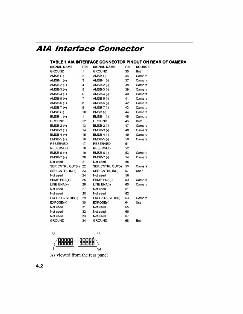
AIA INTERFACE CONNECTORAll the signals referred to in this section are present at the AIA interface connec-tor on the rear panel of the camera. Table 1 lists each signal and its pin number.The connector for this port is a 68 pin, high density, dual row, D type connector.This connector is the same as that used for the �SCSI-2 B cable� interface. Theconnector has .050 pin spacing and a D-type shell that is 2.5 inches long.
DIGITAL VIDEO OUTPUTSThe camera has two digital video output channels, A and B, each with eight bitslabeled MSB through MSB-7. The MSB is the Most Significant Bit and MSB-7is the LSB (Least Significant Bit) in your camera configuration. These signalsare output as differential pairs with signal levels conforming to the RS422specification. The non inverting part of the differential pair is present on theoutput labeled (+), while the inverting part of the differential pair is present onthe output labeled (-).
TIMING OUTPUTSThere are three timing outputs presented on the AIA interface connector. Theyare FRME ENA (frame enable), LINE ENA (line enable) and PIX DATA STRB(pixel data strobe). These signals are output as differential pairs with signallevels conforming to the RS422 specification. The non inverting part of thedifferential pair is present on the (+) output , while the inverting part of thedifferential pair is present on the (-) output. A signal is true when the (+) line ismore positive than the (-) line.
CONTROL INPUTSThe control input EXPOSE is provided as a means of externally synchronizingthe camera. This input is designed to accept RS422 differential, or single endedTTL. To drive this input differentially connect both the (+) and (-) inputs to anRS422 driver. Connect one input to a TTL driver and leave the other inputfloating to drive the EXPOSE input from a single ended signal source.
4.2
AIA Interface Connector
TABLE 1 AIA INTERFTABLE 1 AIA INTERFTABLE 1 AIA INTERFTABLE 1 AIA INTERFTABLE 1 AIA INTERFAAAAACE CONNECTCE CONNECTCE CONNECTCE CONNECTCE CONNECTOR PINOUT ON REAR OF CAMERAOR PINOUT ON REAR OF CAMERAOR PINOUT ON REAR OF CAMERAOR PINOUT ON REAR OF CAMERAOR PINOUT ON REAR OF CAMERASIGNAL NAME PIN SIGNAL NAME PIN SOURCEGROUND 1 GROUND 35 Both
AMSB (+) 2 AMSB (-) 36 Camera
AMSB-1 (+) 3 AMSB-1 (-) 37 Camera
AMSB-2 (+) 4 AMSB-2 (-) 38 Camera
AMSB-3 (+) 5 AMSB-3 (-) 39 Camera
AMSB-4 (+) 6 AMSB-4 (-) 40 Camera
AMSB-5 (+) 7 AMSB-5 (-) 41 Camera
AMSB-6 (+) 8 AMSB-6 (-) 42 Camera
AMSB-7 (+) 9 AMSB-7 (-) 43 Camera
BMSB (+) 10 BMSB (-) 44 Camera
BMSB-1 (+) 11 BMSB-1 (-) 45 Camera
GROUND 12 GROUND 46 Both
BMSB-2 (+) 13 BMSB-2 (-) 47 Camera
BMSB-3 (+) 14 BMSB-3 (-) 48 Camera
BMSB-4 (+) 15 BMSB-4 (-) 49 Camera
BMSB-5 (+) 16 BMSB-5 (-) 50 Camera
RESERVED 17 RESERVED 51
RESERVED 18 RESERVED 52
BMSB-6 (+) 19 BMSB-6 (-) 53 Camera
BMSB-7 (+) 20 BMSB-7 (-) 54 Camera
Not used 21 Not used 55
SER CNTRL OUT(+) 22 SER CNTRL OUT(-) 56 Camera
SER CNTRL IN(+) 23 SER CNTRL IN(-) 57 User
Not used 24 Not used 58
FRME ENA(+) 25 FRME ENA(-) 59 Camera
LINE ENA(+) 26 LINE ENA(-) 60 Camera
Not used 27 Not used 61
Not used 28 Not used 62
PIX DATA STRB(+) 29 PIX DATA STRB(-) 63 Camera
EXPOSE(+) 30 EXPOSE(-) 64 User
Not used 31 Not used 65
Not used 32 Not used 66
Not used 33 Not used 67
GROUND 34 GROUND 68 Both
As viewed from the rear panel1
35 68
34
4.3
Cable Descriptions
TABLE 2 INTERFTABLE 2 INTERFTABLE 2 INTERFTABLE 2 INTERFTABLE 2 INTERFAAAAACE CABLE PIN OUTCE CABLE PIN OUTCE CABLE PIN OUTCE CABLE PIN OUTCE CABLE PIN OUT,,,,,SIGNAL NAME PIN SIGNAL NAME PIN SOURCE
GROUND 1 GROUND 35 Both
AMSB (+) 2 AMSB (-) 36 Camera
AMSB-1 (+) 3 AMSB-1 (-) 37 Camera
AMSB-2 (+) 4 AMSB-2 (-) 38 Camera
AMSB-3 (+) 5 AMSB-3 (-) 39 Camera
AMSB-4 (+) 6 AMSB-4 (-) 40 Camera
AMSB-5 (+) 7 AMSB-5 (-) 41 Camera
AMSB-6 (+) 8 AMSB-6 (-) 42 Camera
AMSB-7 (+) 9 AMSB-7 (-) 43 Camera
BMSB (+) 10 BMSB (-) 44 Camera
BMSB-1 (+) 11 BMSB-1 (-) 45 Camera
GROUND 12 GROUND 46 Both
BMSB-2 (+) 13 BMSB-2 (-) 47 Camera
BMSB-3 (+) 14 BMSB-3 (-) 48 Camera
BMSB-4 (+) 15 BMSB-4 (-) 49 Camera
BMSB-5 (+) 16 BMSB-5 (-) 50 Camera
RESERVED 17 RESERVED 51
RESERVED 18 RESERVED 52
BMSB-6 (+) 19 BMSB-6 (-) 53 Camera
BMSB-7 (+) 20 BMSB-7 (-) 54 Camera
Not used 21 Not used 55
RESERVED 22 RESERVED 56
RESERVED 23 RESERVED 57
Not used 24 Not used 58
FRME ENA(+) 25 FRME ENA(-) 59 Camera
LINE ENA(+) 26 LINE ENA(-) 60 Camera
Not used 27 Not used 61
Not used 28 Not used 62
PIX DATA STRB(+) 29 PIX DATA STRB(-) 63 Camera
EXPOSE(+) 30 EXPOSE(-) 64 User
Not used 31 Not used 65
Not used 32 Not used 66
Not used 33 Not used 67
GROUND 34 GROUND 68 Both
MAMAMAMAMATES WITH PC COM PORTES WITH PC COM PORTES WITH PC COM PORTES WITH PC COM PORTES WITH PC COM PORTTTTTSIGNAL NAME PIN SIGNAL NAME PIN
Open 1 Open 6
Transmit, Cam (TX) 2 Connect to pin 8 7
Receive, User (RX) 3 Connect to pin 7 8
Open 4 Open 9
Ground 5
1
35
34
68
1 6
5
9
4.4
Cable Descriptions
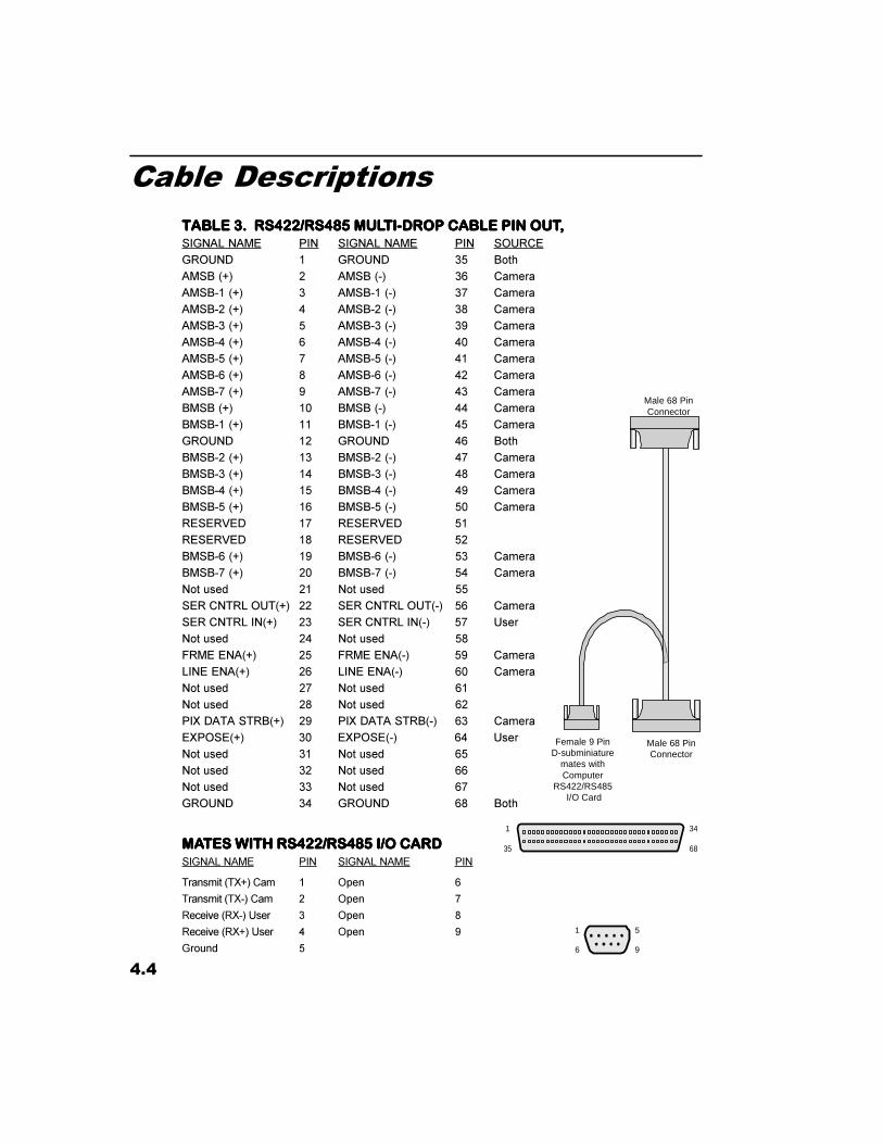
TABLE 3. RS422/RS485 MULTABLE 3. RS422/RS485 MULTABLE 3. RS422/RS485 MULTABLE 3. RS422/RS485 MULTABLE 3. RS422/RS485 MULTI-DROP CABLE PIN OUTTI-DROP CABLE PIN OUTTI-DROP CABLE PIN OUTTI-DROP CABLE PIN OUTTI-DROP CABLE PIN OUT,,,,,SIGNAL NAME PIN SIGNAL NAME PIN SOURCE
GROUND 1 GROUND 35 Both
AMSB (+) 2 AMSB (-) 36 Camera
AMSB-1 (+) 3 AMSB-1 (-) 37 Camera
AMSB-2 (+) 4 AMSB-2 (-) 38 Camera
AMSB-3 (+) 5 AMSB-3 (-) 39 Camera
AMSB-4 (+) 6 AMSB-4 (-) 40 Camera
AMSB-5 (+) 7 AMSB-5 (-) 41 Camera
AMSB-6 (+) 8 AMSB-6 (-) 42 Camera
AMSB-7 (+) 9 AMSB-7 (-) 43 Camera
BMSB (+) 10 BMSB (-) 44 Camera
BMSB-1 (+) 11 BMSB-1 (-) 45 Camera
GROUND 12 GROUND 46 Both
BMSB-2 (+) 13 BMSB-2 (-) 47 Camera
BMSB-3 (+) 14 BMSB-3 (-) 48 Camera
BMSB-4 (+) 15 BMSB-4 (-) 49 Camera
BMSB-5 (+) 16 BMSB-5 (-) 50 Camera
RESERVED 17 RESERVED 51
RESERVED 18 RESERVED 52
BMSB-6 (+) 19 BMSB-6 (-) 53 Camera
BMSB-7 (+) 20 BMSB-7 (-) 54 Camera
Not used 21 Not used 55
SER CNTRL OUT(+) 22 SER CNTRL OUT(-) 56 Camera
SER CNTRL IN(+) 23 SER CNTRL IN(-) 57 User
Not used 24 Not used 58
FRME ENA(+) 25 FRME ENA(-) 59 Camera
LINE ENA(+) 26 LINE ENA(-) 60 Camera
Not used 27 Not used 61
Not used 28 Not used 62
PIX DATA STRB(+) 29 PIX DATA STRB(-) 63 Camera
EXPOSE(+) 30 EXPOSE(-) 64 User
Not used 31 Not used 65
Not used 32 Not used 66
Not used 33 Not used 67
GROUND 34 GROUND 68 Both
MAMAMAMAMATES WITH RS422/RS485 I/O CARDTES WITH RS422/RS485 I/O CARDTES WITH RS422/RS485 I/O CARDTES WITH RS422/RS485 I/O CARDTES WITH RS422/RS485 I/O CARDSIGNAL NAME PIN SIGNAL NAME PIN
Transmit (TX+) Cam 1 Open 6
Transmit (TX-) Cam 2 Open 7
Receive (RX-) User 3 Open 8
Receive (RX+) User 4 Open 9
Ground 5
1
35
34
68
1 6
5
9
Male 68 PinConnector
Male 68 PinConnector
Female 9 PinD-subminiature
mates withComputer
RS422/RS485 I/O Card
4.5
Timing Waveforms
INSERTED WAIT LINE
PROGRAMMEDEXPOSURE
376 µsec @ 85 fpsIDLE LATENCYFOR SYNCFDV
LDV
STROBEOUT
CONTINUOUS MODE - VARIABLE EXPOSURE TIMING
PROGRAMMEDEXPOSURE
FDV
LDV
STROBEOUT
TRIGGERED MODE TIMING
FDV
LDV
25 µS
CONTROLLED MODE TIMINGTRIGGER EXPOSURE
242 LINE PAIRS
242 LINE PAIRS
242 LINE PAIRS
TRIGGER
SYNC JOG
100 nS MIN
TRIGGER 100 nS MIN
20 µS
STROBEOUT
PROGRAMMEDEXPOSURE
FDV
LDV
STROBEOUT
RETRIGGERED MODE TIMING
TRIGGER 100 nS MIN RETRIGGER
242 LINE PAIRSNEW FRAME
20 µS
20 µS
25 µS
25 µS
4.6
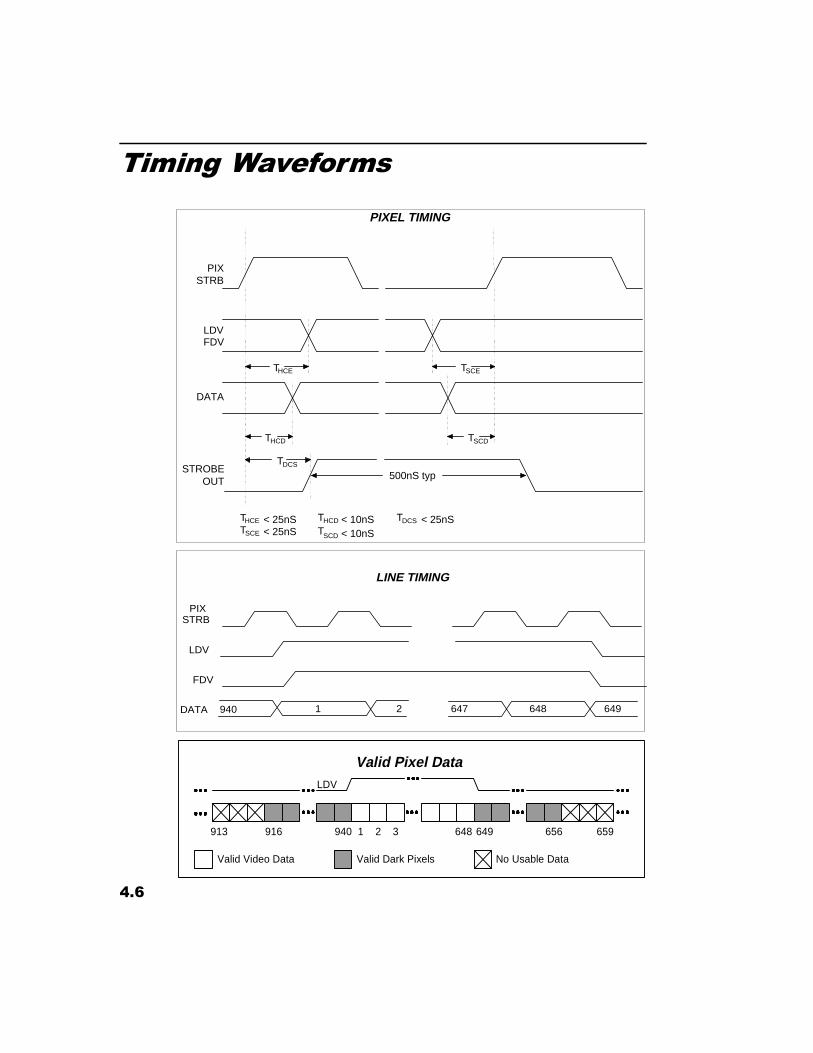
Timing Waveforms
DATA
PIXSTRB
HCET SCET
SCDTHCDT
PIXEL TIMING
LDVFDV
STROBEOUT
DCST500nS typ
HCDT < 10nSSCET < 25nS SCDT < 10nS
DCST < 25nSHCET < 25nS
DATA
PIXSTRB
LDV
LINE TIMING
1 648940 647 6492
FDV
Valid Pixel Data
940 1
LDV
2 3916913 648 649 656 659
Valid Video Data Valid Dark Pixels No Usable Data
4.7
Specifications
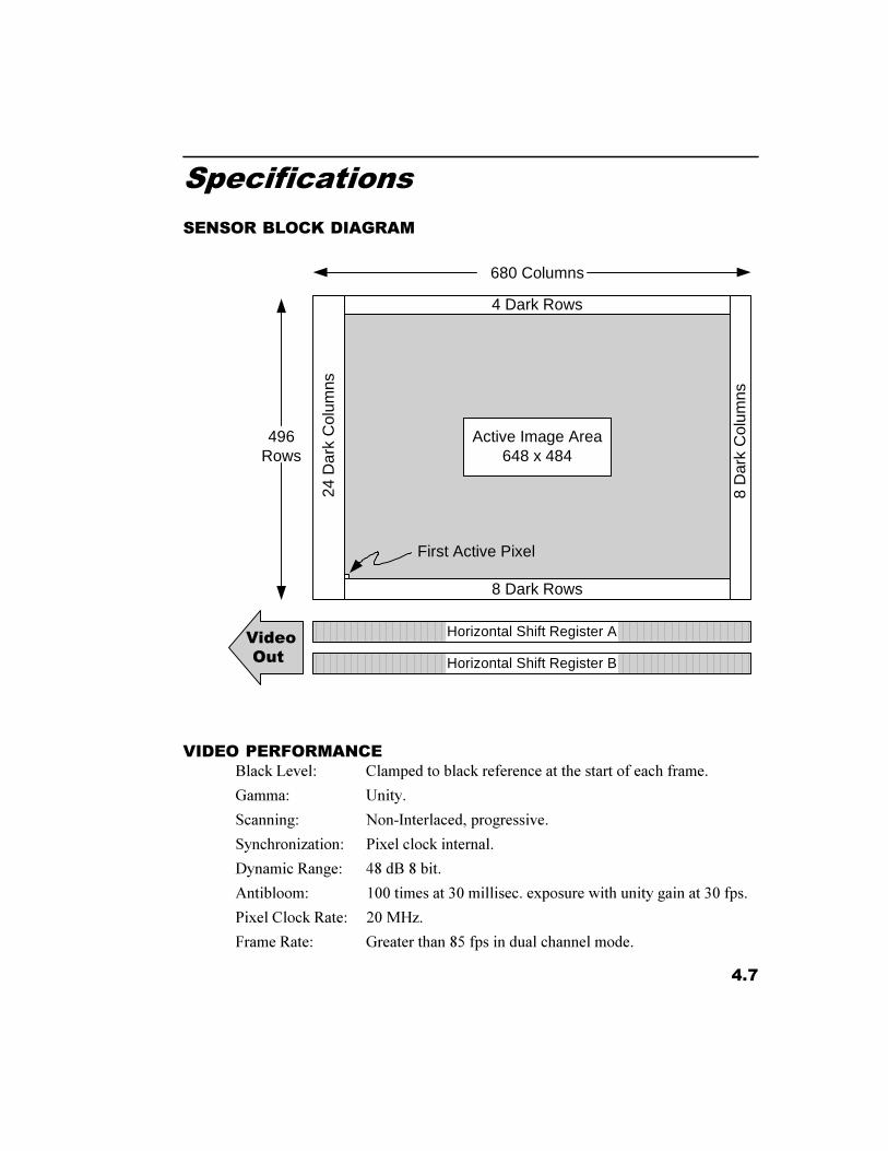
SENSOR BLOCK DIAGRAM
VIDEO PERFORMANCEBlack Level: Clamped to black reference at the start of each frame.
Gamma: Unity.
Scanning: Non-Interlaced, progressive.
Synchronization: Pixel clock internal.
Dynamic Range: 48 dB 8 bit.
Antibloom: 100 times at 30 millisec. exposure with unity gain at 30 fps.
Pixel Clock Rate: 20 MHz.
Frame Rate: Greater than 85 fps in dual channel mode.
Active Image Area648 x 484
4 Dark Rows
8 Dark Rows
8 D
ark
Col
umns
24 D
ark
Col
umns
Horizontal Shift Register B
Horizontal Shift Register A��9LGHR�2XW
680 Columns
496Rows
First Active Pixel
4.8
Specifications
CAMERA MECHANICALHousing: Two piece sheet metal steel case.
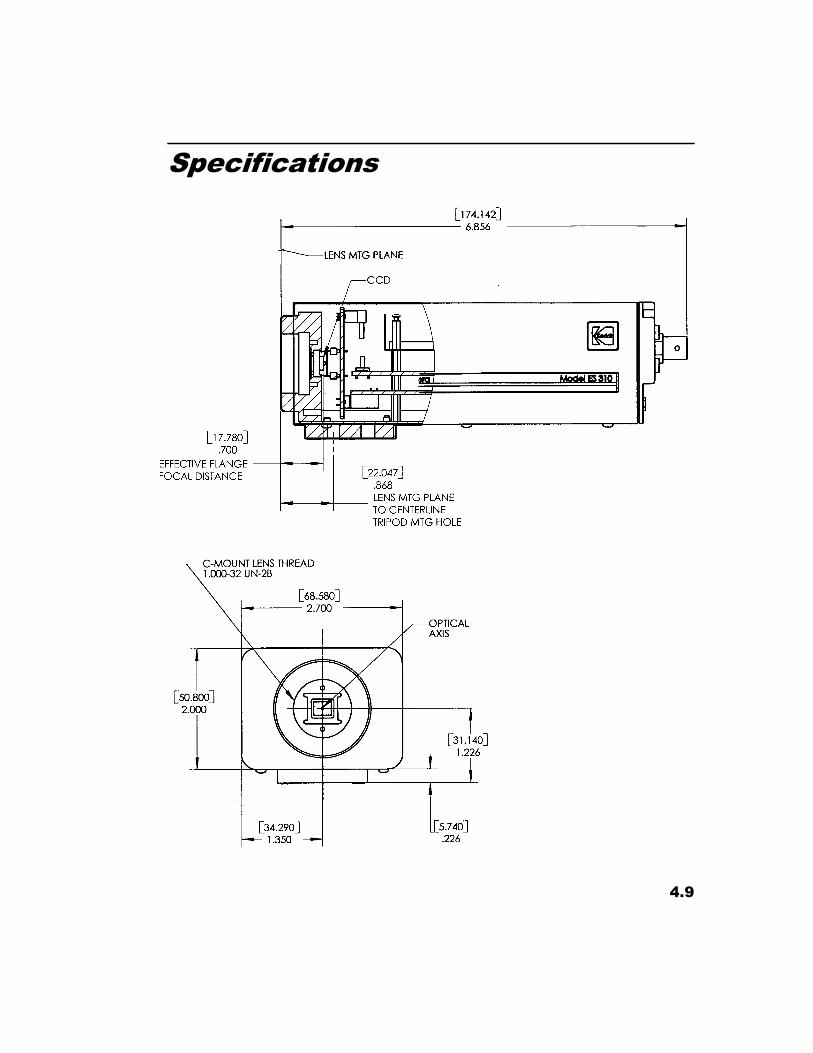
Dimensions: 2.0"H x 2.7"W x 6.0"L (50.8 x 68.6 x 152.4mm)
Lens: C-Mount
Weight: 1.5 lbs approx. (0.68Kgs)
Mount: One 1/4 - 20 threaded hole with additional locating pin hole.
Vibration: 3 g, sinusoidal from 5 to 150 Hz
Shock: 20g (non-operating)
TEMPERATUREOperating: 0 to 40 º C (32 to 104º F), non - condensing (Image quality
will degrade with increasing temperature)
Storage: -25 to +80º C (-13 to 176º F), non-condensing.
HUMIDITYOperational: < 80% @ 40º C (104º F)
Storage: < 40% @ 80º C (176º F)
4.9
Specifications

4.10
Notes