Embed Size (px)
Citation preview
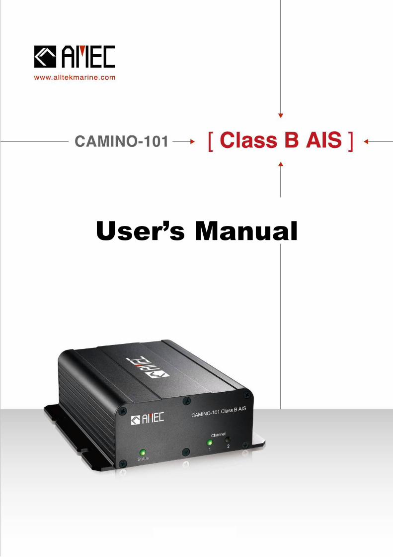
User’s Manual

I
COPYRIGHT
The entire contents of this instruction manual, including any future updates, revisions, and
modifications, shall remain the property of AMEC at all times. Unauthorized copies or
reproduction of this manual, either in part or whole, in any form of print and electronic media, is
prohibited. The contents herein can only be used for the intended purpose of this manual.
DISCLAIMER
AMEC is devoted to publish and maintain this product manual. As we continue to improve our
AIS products to satisfy all customers’ needs, information in this document is subject to change
without notice. AMEC does not make any representations or warranties (implied or otherwise)
regarding the accuracy and completeness of this document and shall in no event be liable for
any loss of profit or any commercial damage, including but not limited to special, incidental,
consequential, or other damage.
Contact us at:
Technical Support:
Sales & Marketing:
ALLTEK MARINE ELECTRONICS CO., LTD
7F, No. 605, Ruei-Guang Rd., Neihu, Taipei, Taiwan 114
TEL: +886 2 2627 1599
FAX: +886 2 2627 1600
www.alltekmarine.com
(Your Local Dealer/Agent Warranty Stamp)
Version 1.83
II
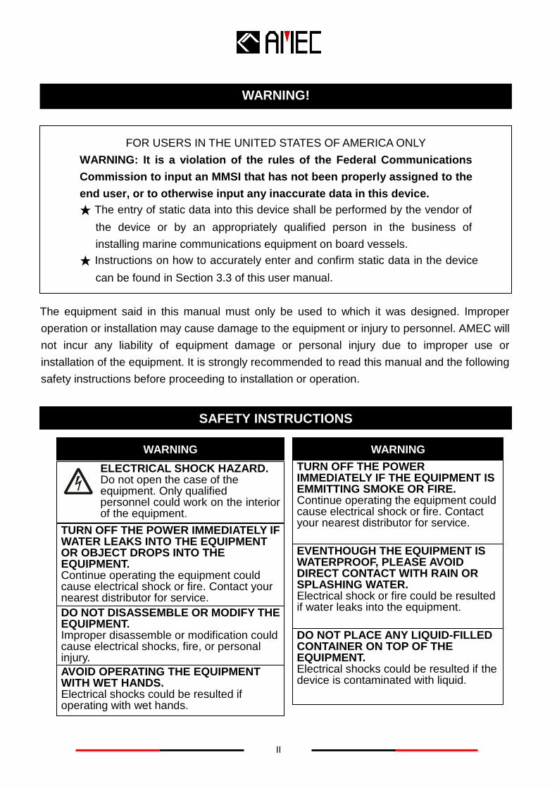
FOR USERS IN THE UNITED STATES OF AMERICA ONLY
WARNING: It is a violation of the rules of the Federal Communications
Commission to input an MMSI that has not been properly assigned to the
end user, or to otherwise input any inaccurate data in this device.
★ The entry of static data into this device shall be performed by the vendor of
the device or by an appropriately qualified person in the business of
installing marine communications equipment on board vessels.
★ Instructions on how to accurately enter and confirm static data in the device
can be found in Section 3.3 of this user manual.
The equipment said in this manual must only be used to which it was designed. Improper
operation or installation may cause damage to the equipment or injury to personnel. AMEC will
not incur any liability of equipment damage or personal injury due to improper use or
installation of the equipment. It is strongly recommended to read this manual and the following
safety instructions before proceeding to installation or operation.
SAFETY INSTRUCTIONS
ELECTRICAL SHOCK HAZARD. Do not open the case of the equipment. Only qualified
personnel could work on the interior of the equipment.
WARNING
TURN OFF THE POWER IMMEDIATELY IF WATER LEAKS INTO THE EQUIPMENT OR OBJECT DROPS INTO THE EQUIPMENT. Continue operating the equipment could cause electrical shock or fire. Contact your nearest distributor for service.
DO NOT DISASSEMBLE OR MODIFY THE EQUIPMENT. Improper disassemble or modification could cause electrical shocks, fire, or personal injury.
WARNING
DO NOT PLACE ANY LIQUID-FILLED CONTAINER ON TOP OF THE EQUIPMENT. Electrical shocks could be resulted if the device is contaminated with liquid.
TURN OFF THE POWER IMMEDIATELY IF THE EQUIPMENT IS EMMITTING SMOKE OR FIRE. Continue operating the equipment could cause electrical shock or fire. Contact your nearest distributor for service.
EVENTHOUGH THE EQUIPMENT IS WATERPROOF, PLEASE AVOID DIRECT CONTACT WITH RAIN OR SPLASHING WATER. Electrical shock or fire could be resulted if water leaks into the equipment.
AVOID OPERATING THE EQUIPMENT WITH WET HANDS. Electrical shocks could be resulted if operating with wet hands.
WARNING!
III
FOREWORD
Congratulations on the purchase of your new CAMINO-101 Automatic Identification System
(hereinafter called “AIS”). Wherever you sail now, you can have a better control of your
surrounding sea, and have an enjoyable voyage.
Camino-101 AIS is strictly tested to meet the rigorous demands of the marine environment.
Unless improper use, installation, or maintenance, the equipment should function properly at its
optimum.
We thank you for choosing our product and we wish you bon voyage!
Table of Contents
I. COPYRIGHT & DISCLAIMER
II. WARNING & SAFETY INSTRUCTION
III. FORWARD
Page
1 INTRODUCTION ............................................................................................. 1
1.1 CAMINO-101 Overview ................................................................................................. 1
1.2 Type of AIS .................................................................................................................... 2
1.3 AIS Message Type ........................................................................................................ 2
1.4 AIS Report Rate ............................................................................................................ 3
1.5 About this Manual ........................................................................................................ 3
1.6 Important Notice ........................................................................................................... 3
2 INSTALLATION ............................................................................................... 4
2.1 General .......................................................................................................................... 4
2.1.1 Safety Instructions .................................................................................................. 4
2.1.2 Unpacking and Handling the Unit .......................................................................... 5
2.1.3 Items in the Package ............................................................................................... 5
2.2 Installation Procedure .................................................................................................. 6
2.2.1 Installation Precautions .......................................................................................... 6
2.2.2 Step by Step Installation Instructions ................................................................... 7
2.2.3 Connector Pin Definition and Cable Wiring ......................................................... 11
2.2.4 VHF Antenna Installation ...................................................................................... 15
2.2.5 GPS Antenna Installation ...................................................................................... 16
2.2.6 Antenna Cabling .................................................................................................... 16
2.2.7 CAMINO-101 External Connections ..................................................................... 17
2.2.8 AMEC AIS Configuration Software Installation ................................................... 18
2.3 AMEC AIS Viewer Software Installation .................................................................... 22
2.4 Bluetooth Pairing (Optional Feature) (CAMINO-101W only) ................................... 25
3 GET STARTED .............................................................................................. 26
3.1 Turning Power ON / OFF ............................................................................................ 26
3.2 Front Panel LED Indicators ....................................................................................... 27
3.2.1 Built-in Integrity Test (BIIT) ................................................................................... 28
3.3 CAMINO-101 Configuration Settings ........................................................................ 29
3.3.1 Configuration Settings .......................................................................................... 29
3.3.2 Diagnosis Functions ............................................................................................. 33
4 AMEC AIS VIEWER DESCRIPTION ............................................................. 36
4.1 RS-232 Serial Port Selection ..................................................................................... 36
4.2 Running AMEC AIS Viewer ........................................................................................ 37
4.3 Display Indications ..................................................................................................... 39
4.3.1 Area 1: Screen View .............................................................................................. 40
4.3.2 Area 2: Main Menu ................................................................................................. 44
4.3.3 Area 3: My Vessel’s position information ............................................................ 55
4.3.4 Area 4: Ship List .................................................................................................... 56
4.3.5 Area 5: Ship Details Information .......................................................................... 57
5 APPENDIX .................................................................................................... 61
5.1 Product Specifications ............................................................................................... 61
5.2 Dimensions ................................................................................................................. 65
5.3 Ordering Information .................................................................................................. 66
5.4 Accessories ................................................................................................................ 66
5.5 Trouble Shooting ........................................................................................................ 67
5.5.1 Diagnosis by LED Indicators ................................................................................ 67
5.5.2 Problem Analysis .................................................................................................. 68
6 AMEC WORLD WIDE WARRANTY .............................................................. 70
7 FEDERAL COMMUNICATION COMMISSION INTERFERENCE STATEMENT
............................................................................................................................ 72
8 DECLARATION OF CONFORMITY .............................................................. 73
9 INDUSTRY CANADA NOTICE TO USERS ................................................... 73
10 ABBREVIATIONS ....................................................................................... 73

1
1 INTRODUCTION
1.1 CAMINO-101 Overview
The CAMINO-101 is a Class B AIS transponder using carrier-sense TDMA (CSTDMA) technology.
It is designed to be inter-operable and compatible with Class A or other Class B ship-borne AIS
stations or any other AIS stations operating on the AIS VHF data link.
CAMINO-101 AIS uses marine VHF channels with frequency set universally from 156.025 MHz to
162.025 MHz. Having CAMINO-101 AIS on board, not only can you monitor the status of the
vessels in the surrounding area, but also receive the dynamic information (position, speed, SOG,
and etc.), static information (ship name, MMSI, call sign, and etc.), and voyage related information
(cargo type, destination, and etc.) from any vessels equipped with AIS. An external computer
installed with AMEC AIS Viewer software or an AIS-ready plotter device is required in order to
view the AIS information above mentioned.
CAMINO-101 AIS is one of the cutting-edge navigational aid equipments allowing real-time
information exchanges within the AIS network. It is also capable of integrating with other maritime
systems such as Electronic Chart System (hereinafter called “ECS”) for various maritime
navigation applications.
CAMINO-101 is designed with 2 RF receivers and 1 RF transmitter. One of the RF receivers is
time-shared between AIS and DSC. On the front panel, CAMINO-101 is equipped with 3 LED
indicators. At rear panel, there are 1 VHF antenna connector, 1 GPS antenna connector, 1
optional Bluetooth connector and antenna (CAMINO-101W only), 1 NMEA interface connector, 1
RS232 interface connector (CAMINO-101A/W supports Tx-Off Switch Box via this connector), 1
power connector, and 1 power switch.
NOTE: The CAMINO-101 is an equipment to be used in protected environmental conditions. It is not intended to expose to rain or spray longer than a minute.
2
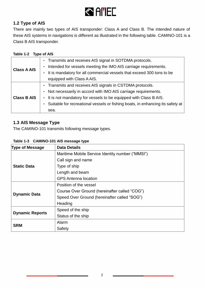
1.2 Type of AIS
There are mainly two types of AIS transponder: Class A and Class B. The intended nature of
these AIS systems in navigations is different as illustrated in the following table. CAMINO-101 is a
Class B AIS transponder.
Table 1-2 Type of AIS
Class A AIS
‧ Transmits and receives AIS signal in SOTDMA protocols.
‧ Intended for vessels meeting the IMO AIS carriage requirements.
‧ It is mandatory for all commercial vessels that exceed 300 tons to be
equipped with Class A AIS.
Class B AIS
‧ Transmits and receives AIS signals in CSTDMA protocols.
‧ Not necessarily in accord with IMO AIS carriage requirements.
‧ It is not mandatory for vessels to be equipped with Class B AIS.
‧ Suitable for recreational vessels or fishing boats, in enhancing its safety at
sea.
1.3 AIS Message Type
The CAMINO-101 transmits following message types.
Table 1-3 CAMINO-101 AIS message type
Type of Message Data Details
Static Data
Maritime Mobile Service Identity number (“MMSI”)
Call sign and name
Type of ship
Length and beam
GPS Antenna location
Dynamic Data Position of the vessel
Course Over Ground (hereinafter called “COG”)
Speed Over Ground (hereinafter called “SOG”)
Heading
Dynamic Reports Speed of the ship
Status of the ship
SRM Alarm
Safety
3
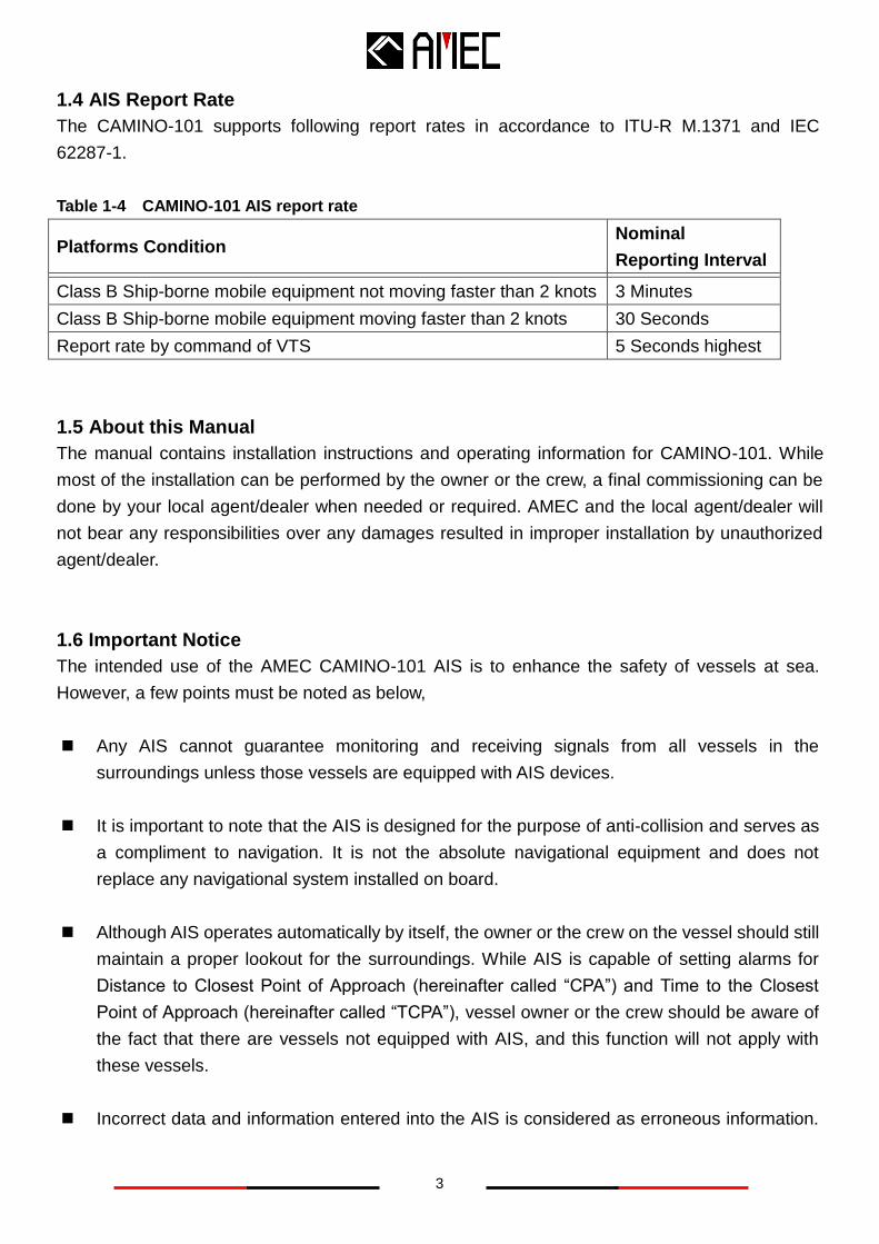
1.4 AIS Report Rate
The CAMINO-101 supports following report rates in accordance to ITU-R M.1371 and IEC
62287-1.
Table 1-4 CAMINO-101 AIS report rate
Platforms Condition Nominal
Reporting Interval Class B Ship-borne mobile equipment not moving faster than 2 knots 3 Minutes Class B Ship-borne mobile equipment moving faster than 2 knots 30 Seconds Report rate by command of VTS 5 Seconds highest
1.5 About this Manual
The manual contains installation instructions and operating information for CAMINO-101. While
most of the installation can be performed by the owner or the crew, a final commissioning can be
done by your local agent/dealer when needed or required. AMEC and the local agent/dealer will
not bear any responsibilities over any damages resulted in improper installation by unauthorized
agent/dealer.
1.6 Important Notice
The intended use of the AMEC CAMINO-101 AIS is to enhance the safety of vessels at sea.
However, a few points must be noted as below,
Any AIS cannot guarantee monitoring and receiving signals from all vessels in the
surroundings unless those vessels are equipped with AIS devices.
It is important to note that the AIS is designed for the purpose of anti-collision and serves as
a compliment to navigation. It is not the absolute navigational equipment and does not
replace any navigational system installed on board.
Although AIS operates automatically by itself, the owner or the crew on the vessel should still
maintain a proper lookout for the surroundings. While AIS is capable of setting alarms for
Distance to Closest Point of Approach (hereinafter called “CPA”) and Time to the Closest
Point of Approach (hereinafter called “TCPA”), vessel owner or the crew should be aware of
the fact that there are vessels not equipped with AIS, and this function will not apply with
these vessels.
Incorrect data and information entered into the AIS is considered as erroneous information.
4
WARNING
Warning 注意
Erroneous information or improper configuration will cause risk to both own vessel and
surrounding vessels when these information are transmitted. Users must be aware of this
risk and ensure that all information entered into the system is correct and up-to-date.
2 INSTALLATION
2.1 General
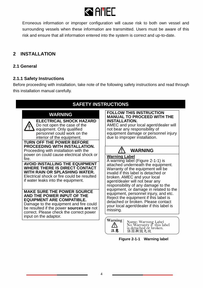
2.1.1 Safety Instructions
Before proceeding with installation, take note of the following safety instructions and read through
this installation manual carefully.
SAFETY INSTRUCTION SAFETY INSTRUCTIONS
ELECTRICAL SHOCK HAZARD Do not open the case of the equipment. Only qualified
personnel could work on the interior of the equipment.
WARNING
TURN OFF THE POWER BEFORE PROCEEDING WITH INSTALLATION. Proceeding with installation with the power on could cause electrical shock or fire.
AVOID INSTALLING THE EQUIPMENT WHERE THERE IS DIRECT CONTACT WITH RAIN OR SPLASHING WATER. Electrical shock or fire could be resulted if water leaks into the equipment.
FOLLOW THIS INSTRUCTION MANUAL TO PROCEED WITH THE INSTALLATION. AMEC and your local agent/dealer will not bear any responsibility of equipment damage or personnel injury due to improper installation.
Warning Label A warning label (Figure 2-1-1) is attached underneath the equipment. Warranty of the equipment will be invalid if this label is detached or broken. AMEC and your local agent/dealer will not bear any responsibility of any damage to the equipment, or damage in related to the equipment, personnel injury, and etc. Reject the equipment if this label is detached or broken. Please contact your local agent/dealer if this label is missing.
MAKE SURE THE POWER SOURCE AND THE POWER INPUT OF THE EQUIPMENT ARE COMPATIBLE. Damage to the equipment and fire could be resulted if the power sources are not correct. Please check the correct power input on the adaptor.
Figure 2-1-1 Warning label
Name: Warning Label No Warranty if this label is detached or broken. 保固撕毁无效
5
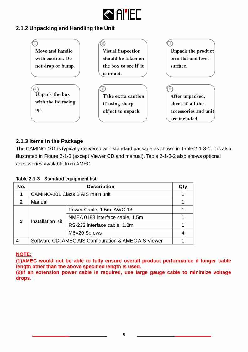
2.1.2 Unpacking and Handling the Unit
2.1.3 Items in the Package
The CAMINO-101 is typically delivered with standard package as shown in Table 2-1-3-1. It is also
illustrated in Figure 2-1-3 (except Viewer CD and manual). Table 2-1-3-2 also shows optional
accessories available from AMEC.
Table 2-1-3 Standard equipment list
No. Description Qty
1 CAMINO-101 Class B AIS main unit 1
2 Manual 1
3 Installation Kit
Power Cable, 1.5m, AWG 18 1
NMEA 0183 interface cable, 1.5m 1
RS-232 interface cable, 1.2m 1
M6×20 Screws 4
4 Software CD: AMEC AIS Configuration & AMEC AIS Viewer 1
NOTE:
(1)AMEC would not be able to fully ensure overall product performance if longer cable length other than the above specified length is used. (2)If an extension power cable is required, use large gauge cable to minimize voltage drops.
Unpack the product
on a flat and level
surface.
Move and handle
with caution. Do
not drop or bump.
Unpack the box
with the lid facing
up.
Visual inspection
should be taken on
the box to see if it
is intact.
Take extra caution
if using sharp
object to unpack.
1 2 3
4 5 6
After unpacked,
check if all the
accessories and unit
are included.
6
2.1.3.1 Optional Supply
Table 2-1-3-1 Optional equipment list
No. Description Remarks
1 VHF Antenna --
2 GPS Antenna 10m cable included
3 VHF Antenna Cable 10m
NOTE: AMEC would not be able to fully ensure overall product performance if longer cable
length other than the above specified length is used.
2.2 Installation Procedure
2.2.1 Installation Precautions
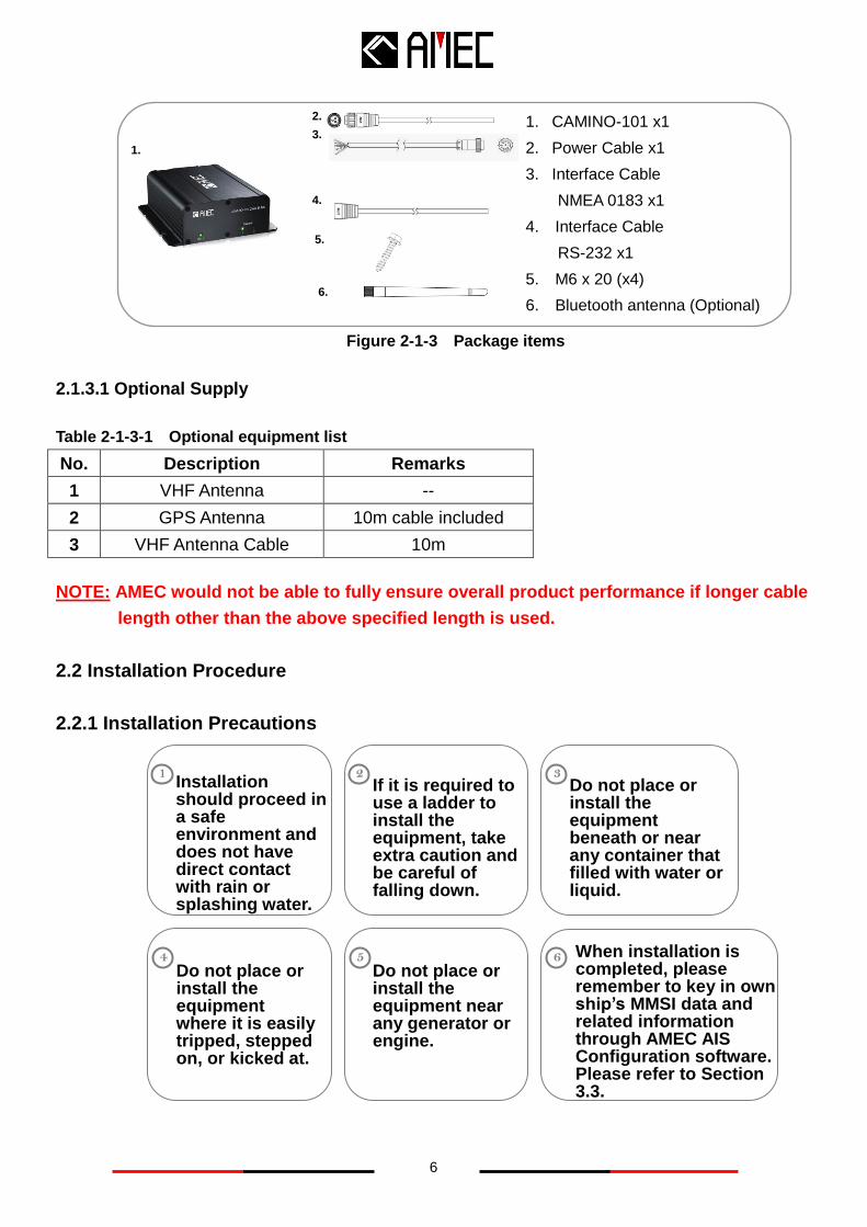
Figure 2-1-3 Package items
Do not place or install the equipment near any generator or engine.
5
Do not place or install the equipment beneath or near any container that filled with water or liquid.
3
Do not place or install the equipment where it is easily tripped, stepped on, or kicked at.
Installation should proceed in a safe environment and does not have direct contact with rain or splashing water.
1
When installation is completed, please remember to key in own ship’s MMSI data and related information through AMEC AIS Configuration software. Please refer to Section 3.3.
6
If it is required to use a ladder to install the equipment, take extra caution and be careful of falling down.
2
1. CAMINO-101 x1
2. Power Cable x1
3. Interface Cable
NMEA 0183 x1
4. Interface Cable
RS-232 x1
5. M6 x 20 (x4)
6. Bluetooth antenna (Optional)
1.
3.
2.
5.
4.
6.
4
7
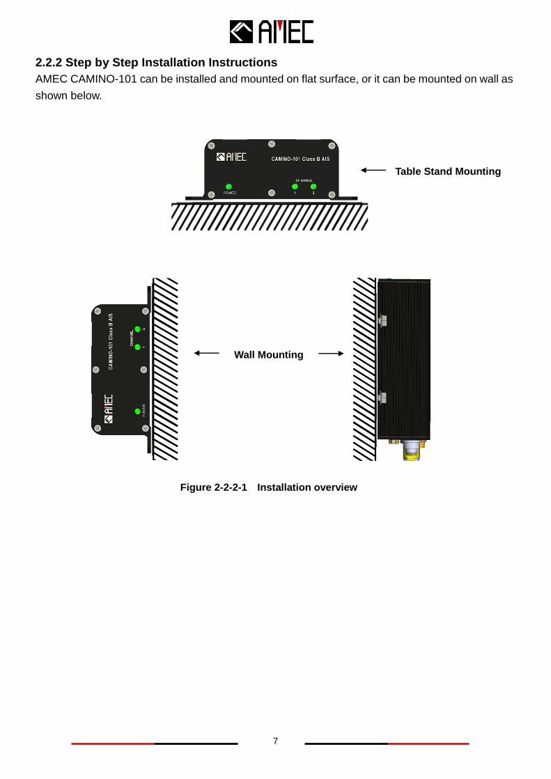
2.2.2 Step by Step Installation Instructions
AMEC CAMINO-101 can be installed and mounted on flat surface, or it can be mounted on wall as
shown below.
Wall Mounting
Figure 2-2-2-1 Installation overview
Table Stand Mounting
8
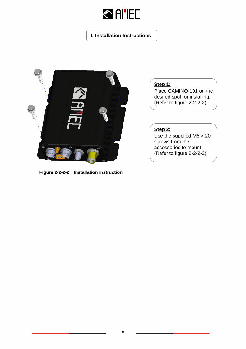
I. Installation Instructions
Step 1:
Place CAMINO-101 on the desired spot for installing. (Refer to figure 2-2-2-2)
Figure 2-2-2-2 Installation instruction
Step 2:
Use the supplied M6 × 20 screws from the accessories to mount. (Refer to figure 2-2-2-2)
9
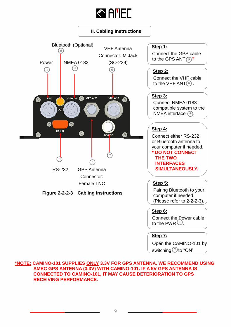
*NOTE: CAMINO-101 SUPPLIES ONLY 3.3V FOR GPS ANTENNA. WE RECOMMEND USING AMEC GPS ANTENNA (3.3V) WITH CAMINO-101. IF A 5V GPS ANTENNA IS CONNECTED TO CAMINO-101, IT MAY CAUSE DETERIORATION TO GPS RECEIVING PERFORMANCE.
Step 3:
II. Cabling Instructions
Step 1:
Connect the GPS cable to the GPS ANT * 5
Step 2:
Connect the VHF cable to the VHF ANT . 6
Connect NMEA 0183 compatible system to the
NMEA interface . 4
Figure 2-2-2-3 Cabling instructions
GPS Antenna
Connector:
Female TNC
type
1
5 3
6
2 VHF Antenna
Connector: M Jack
(SO-239) Power
RS-232
NMEA 0183
Step 4:
Connect either RS-232 or Bluetooth antenna to your computer if needed. * DO NOT CONNECT
THE TWO INTERFACES
SIMULTANEOUSLY.
Step 6:
Connect the Power cable to the PWR .
1
Step 5:
Pairing Bluetooth to your computer if needed.
(Please refer to 2-2-2-3).
4
Bluetooth (Optional)
Step 7:
Open the CAMINO-101 by
switching to “ON” 7
7
10
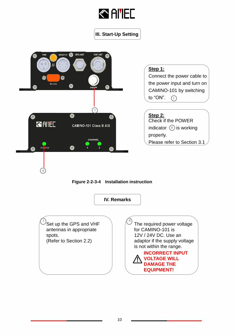
IV. Remarks
Step 1:
Connect the power cable to
the power input and turn on
CAMINO-101 by switching
to “ON”.
III. Start-Up Setting
Set up the GPS and VHF antennas in appropriate spots.
(Refer to Section 2.2)
1 The required power voltage for CAMINO-101 is 12V / 24V DC. Use an adaptor if the supply voltage is not within the range.
2
Step 2: Check if the POWER
indicator is working
properly.
Please refer to Section 3.1
2
INCORRECT INPUT VOLTAGE WILL DAMAGE THE
EQUIPMENT!
Figure 2-2-3-4 Installation instruction
2
1
1
11
2.2.3 Connector Pin Definition and Cable Wiring
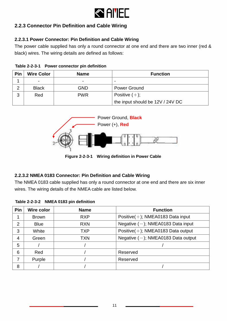
2.2.3.1 Power Connector: Pin Definition and Cable Wiring
The power cable supplied has only a round connector at one end and there are two inner (red &
black) wires. The wiring details are defined as follows:
Pin Wire Color Name Function
1 - - -
2 Black GND Power Ground
3 Red PWR Positive (+);
the input should be 12V / 24V DC
Figure 2-2-3-1 Wiring definition in Power Cable
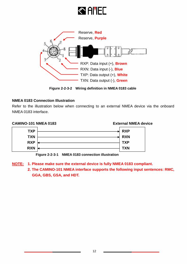
2.2.3.2 NMEA 0183 Connector: Pin Definition and Cable Wiring
The NMEA 0183 cable supplied has only a round connector at one end and there are six inner
wires. The wiring details of the NMEA cable are listed below.
Pin Wire color Name Function
1 Brown RXP Positive(+); NMEA0183 Data input
2 Blue RXN Negative (-); NMEA0183 Data input
3 White TXP Positive(+); NMEA0183 Data output
4 Green TXN Negative (-); NMEA0183 Data output
5 / / /
6 Red / Reserved
7 Purple / Reserved
8 / / /
Table 2-2-3-1 Power connector pin definition
Table 2-2-3-2 NMEA 0183 pin definition
Power Ground, Black
Power (+), Red
12
NMEA 0183 Connection Illustration
Refer to the illustration below when connecting to an external NMEA device via the onboard
NMEA 0183 interface.
NOTE: 1. Please make sure the external device is fully NMEA 0183 compliant.
2. The CAMINO-101 NMEA interface supports the following input sentences: RMC,
GGA, GBS, GSA, and HDT.
TXP
TXN
RXP
RXN
RXP
RXN
TXP
TXN
Figure 2-2-3-1 NMEA 0183 connection illustration
CAMINO-101 NMEA 0183 External NMEA device
RXP: Data input (+), Brown
RXN: Data input (-), Blue
TXP: Data output (+), White
TXN: Data output (-), Green
Reserve, Red
Reserve, Purple
Figure 2-2-3-2 Wiring definition in NMEA 0183 cable
13
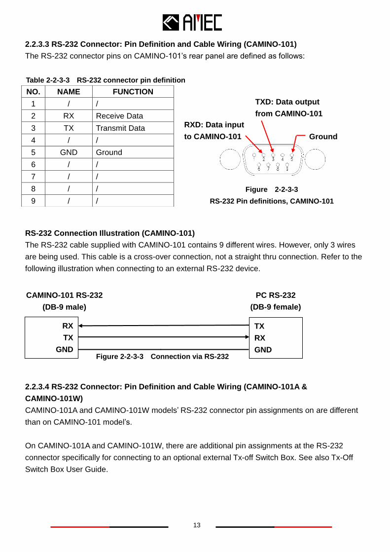
2.2.3.3 RS-232 Connector: Pin Definition and Cable Wiring (CAMINO-101)
The RS-232 connector pins on CAMINO-101’s rear panel are defined as follows:
RS-232 Connection Illustration (CAMINO-101)
The RS-232 cable supplied with CAMINO-101 contains 9 different wires. However, only 3 wires
are being used. This cable is a cross-over connection, not a straight thru connection. Refer to the
following illustration when connecting to an external RS-232 device.
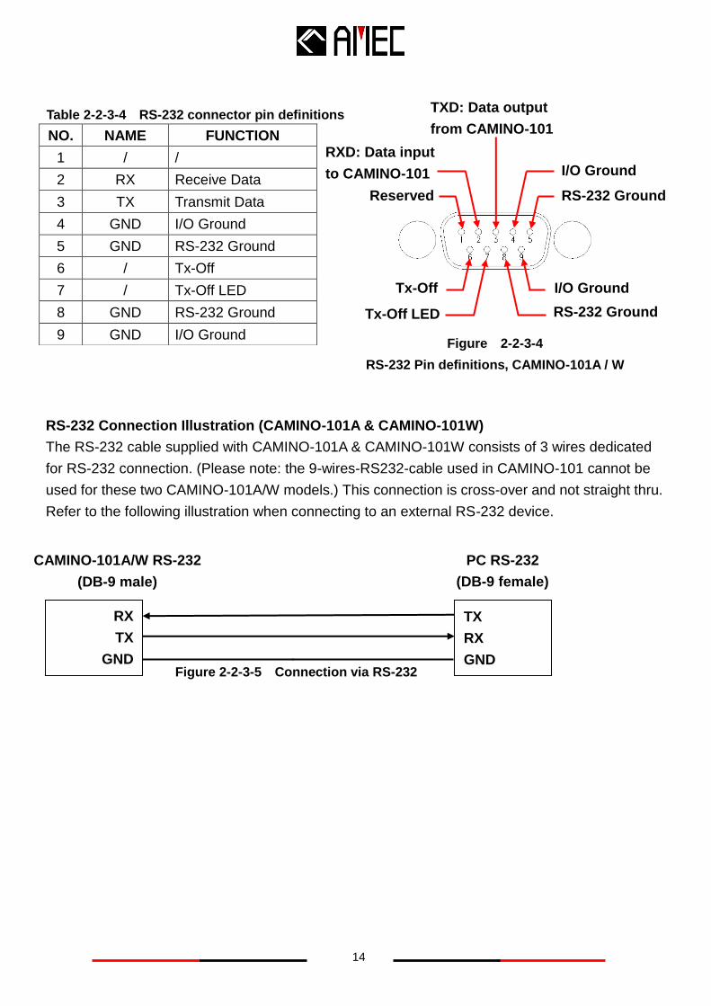
2.2.3.4 RS-232 Connector: Pin Definition and Cable Wiring (CAMINO-101A &
CAMINO-101W)
CAMINO-101A and CAMINO-101W models’ RS-232 connector pin assignments on are different
than on CAMINO-101 model’s.
On CAMINO-101A and CAMINO-101W, there are additional pin assignments at the RS-232
connector specifically for connecting to an optional external Tx-off Switch Box. See also Tx-Off
Switch Box User Guide.
NO. NAME FUNCTION
1 / /
2 RX Receive Data
3 TX Transmit Data
4 / /
5 GND Ground
6 / /
7 / /
8 / /
9 / /
Table 2-2-3-3 RS-232 connector pin definition
TXD: Data output
from CAMINO-101
Ground
RXD: Data input
to CAMINO-101
Figure 2-2-3-3
RS-232 Pin definitions, CAMINO-101
RX
TX
GND
TX
RX
GND
CAMINO-101 RS-232
(DB-9 male)
PC RS-232
(DB-9 female)
Figure 2-2-3-3 Connection via RS-232
14
RS-232 Connection Illustration (CAMINO-101A & CAMINO-101W)
The RS-232 cable supplied with CAMINO-101A & CAMINO-101W consists of 3 wires dedicated
for RS-232 connection. (Please note: the 9-wires-RS232-cable used in CAMINO-101 cannot be
used for these two CAMINO-101A/W models.) This connection is cross-over and not straight thru.
Refer to the following illustration when connecting to an external RS-232 device.
NO. NAME FUNCTION
1 / /
2 RX Receive Data
3 TX Transmit Data
4 GND I/O Ground
5 GND RS-232 Ground
6 / Tx-Off
7 / Tx-Off LED
8 GND RS-232 Ground
9 GND I/O Ground
TXD: Data output
from CAMINO-101
RS-232 Ground
RXD: Data input
to CAMINO-101 I/O Ground
RS-232 Ground
I/O Ground
Reserved
Tx-Off LED
Tx-Off
Figure 2-2-3-4
RS-232 Pin definitions, CAMINO-101A / W
Table 2-2-3-4 RS-232 connector pin definitions
RX
TX
GND
TX
RX
GND
CAMINO-101A/W RS-232
(DB-9 male)
PC RS-232
(DB-9 female)
Figure 2-2-3-5 Connection via RS-232
15
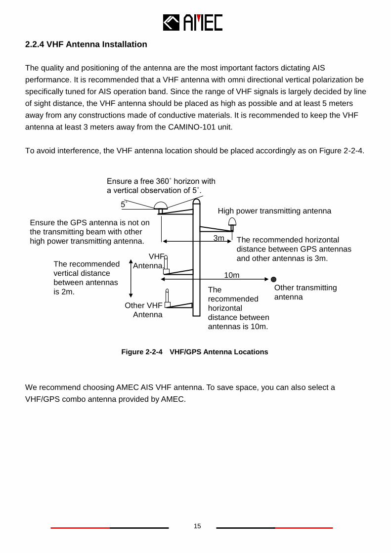
2.2.4 VHF Antenna Installation
The quality and positioning of the antenna are the most important factors dictating AIS
performance. It is recommended that a VHF antenna with omni directional vertical polarization be
specifically tuned for AIS operation band. Since the range of VHF signals is largely decided by line
of sight distance, the VHF antenna should be placed as high as possible and at least 5 meters
away from any constructions made of conductive materials. It is recommended to keep the VHF
antenna at least 3 meters away from the CAMINO-101 unit.
To avoid interference, the VHF antenna location should be placed accordingly as on Figure 2-2-4.
Figure 2-2-4 VHF/GPS Antenna Locations
We recommend choosing AMEC AIS VHF antenna. To save space, you can also select a
VHF/GPS combo antenna provided by AMEC.
Ensure a free 360˚ horizon with a vertical observation of 5˚.
5˚ High power transmitting antenna
3m
Ensure the GPS antenna is not on the transmitting beam with other
high power transmitting antenna.
VHF Antenna.
Other VHF Antenna
The recommended vertical distance between antennas
is 2m. The recommended horizontal distance between antennas is 10m.
Other transmitting
antenna
10m
The recommended horizontal distance between GPS antennas
and other antennas is 3m.
16
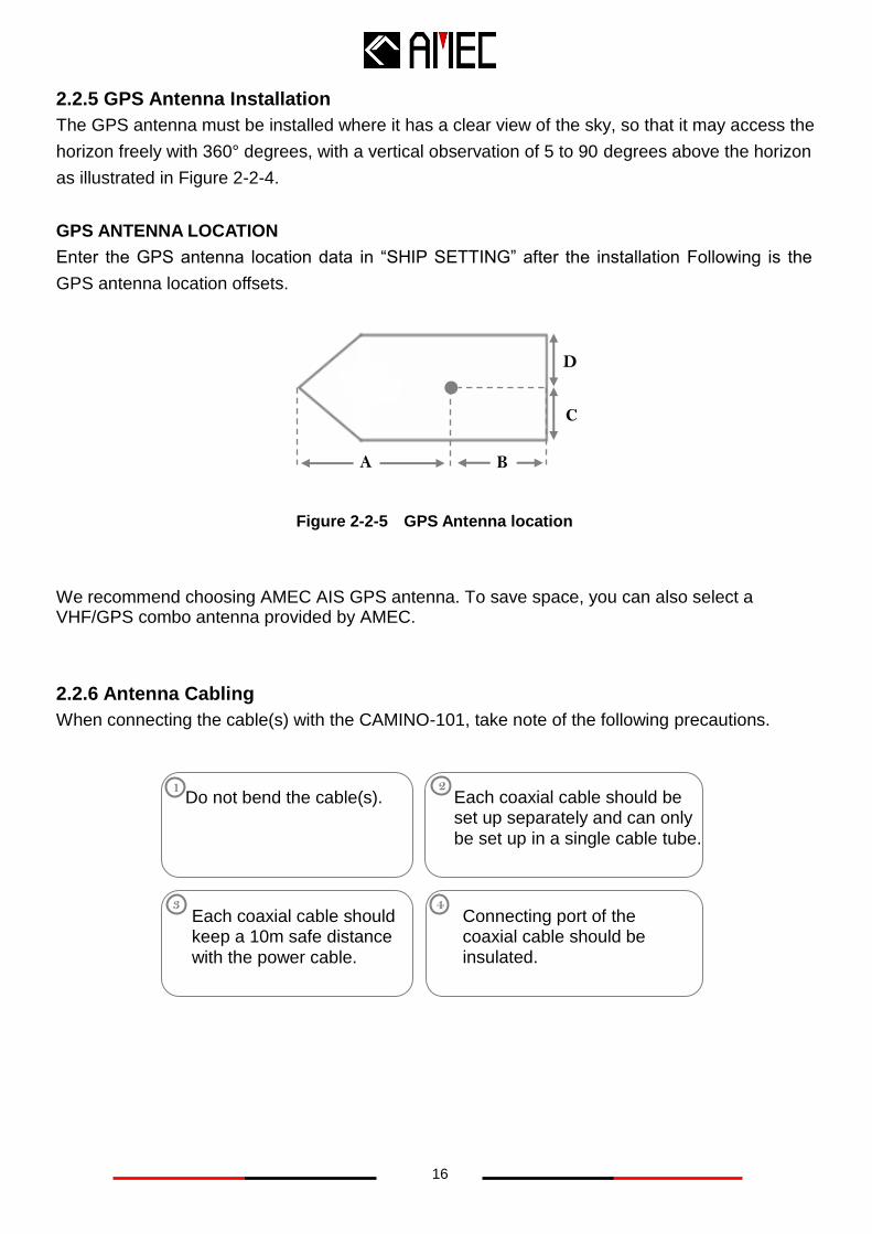
2.2.5 GPS Antenna Installation
The GPS antenna must be installed where it has a clear view of the sky, so that it may access the
horizon freely with 360° degrees, with a vertical observation of 5 to 90 degrees above the horizon
as illustrated in Figure 2-2-4.
GPS ANTENNA LOCATION
Enter the GPS antenna location data in “SHIP SETTING” after the installation Following is the
GPS antenna location offsets.
Figure 2-2-5 GPS Antenna location
We recommend choosing AMEC AIS GPS antenna. To save space, you can also select a VHF/GPS combo antenna provided by AMEC.
2.2.6 Antenna Cabling
When connecting the cable(s) with the CAMINO-101, take note of the following precautions.
Each coaxial cable should be set up separately and can only
be set up in a single cable tube.
Each coaxial cable should keep a 10m safe distance
with the power cable.
Connecting port of the coaxial cable should be insulated.
Do not bend the cable(s). 1 2
3 4
B
C
D
A
17
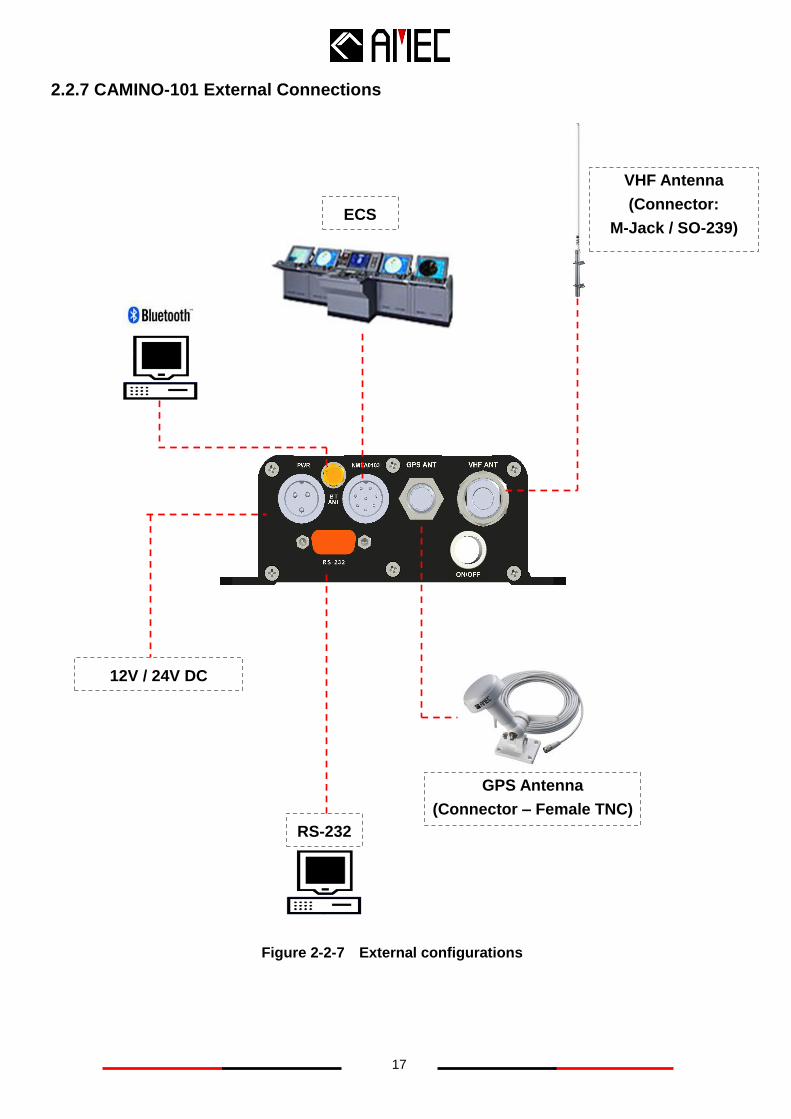
2.2.7 CAMINO-101 External Connections
Figure 2-2-7 External configurations
12V / 24V DC
GPS Antenna
(Connector – Female TNC)
ECS
RS-232
VHF Antenna
(Connector:
M-Jack / SO-239)
18
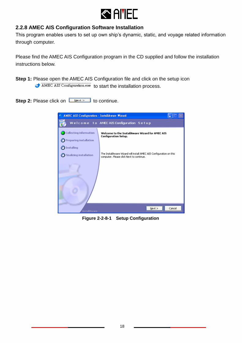
2.2.8 AMEC AIS Configuration Software Installation
This program enables users to set up own ship’s dynamic, static, and voyage related information
through computer.
Please find the AMEC AIS Configuration program in the CD supplied and follow the installation
instructions below.
Step 1: Please open the AMEC AIS Configuration file and click on the setup icon
to start the installation process.
Step 2: Please click on to continue.
Figure 2-2-8-1 Setup Configuration
19
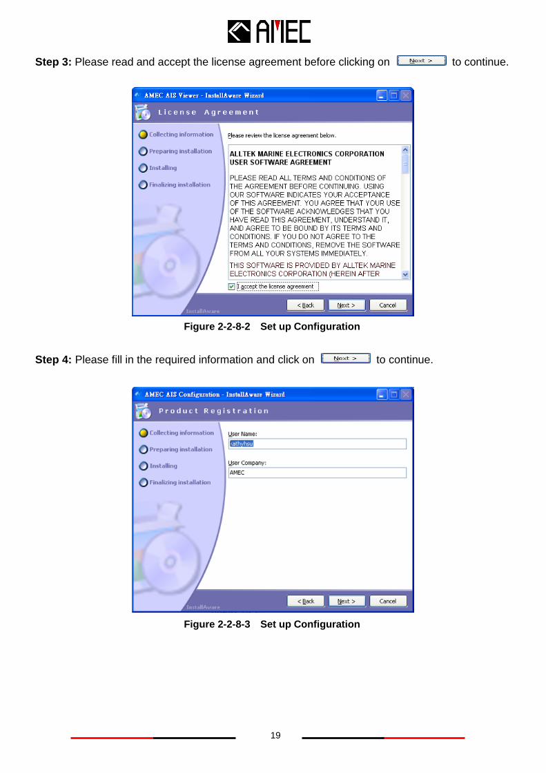
Step 3: Please read and accept the license agreement before clicking on to continue.
Figure 2-2-8-2 Set up Configuration
Step 4: Please fill in the required information and click on to continue.
Figure 2-2-8-3 Set up Configuration
20
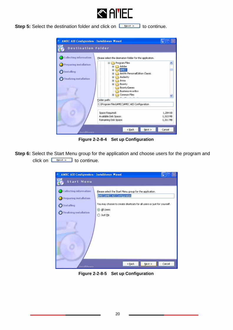
Step 5: Select the destination folder and click on to continue.
Figure 2-2-8-4 Set up Configuration
Step 6: Select the Start Menu group for the application and choose users for the program and
click on to continue.
Figure 2-2-8-5 Set up Configuration
21
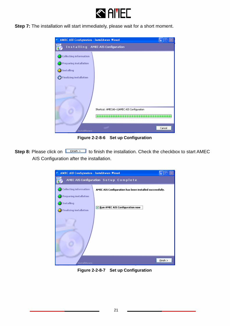
Step 7: The installation will start immediately, please wait for a short moment.
Figure 2-2-8-6 Set up Configuration
Step 8: Please click on to finish the installation. Check the checkbox to start AMEC
AIS Configuration after the installation.
Figure 2-2-8-7 Set up Configuration
22
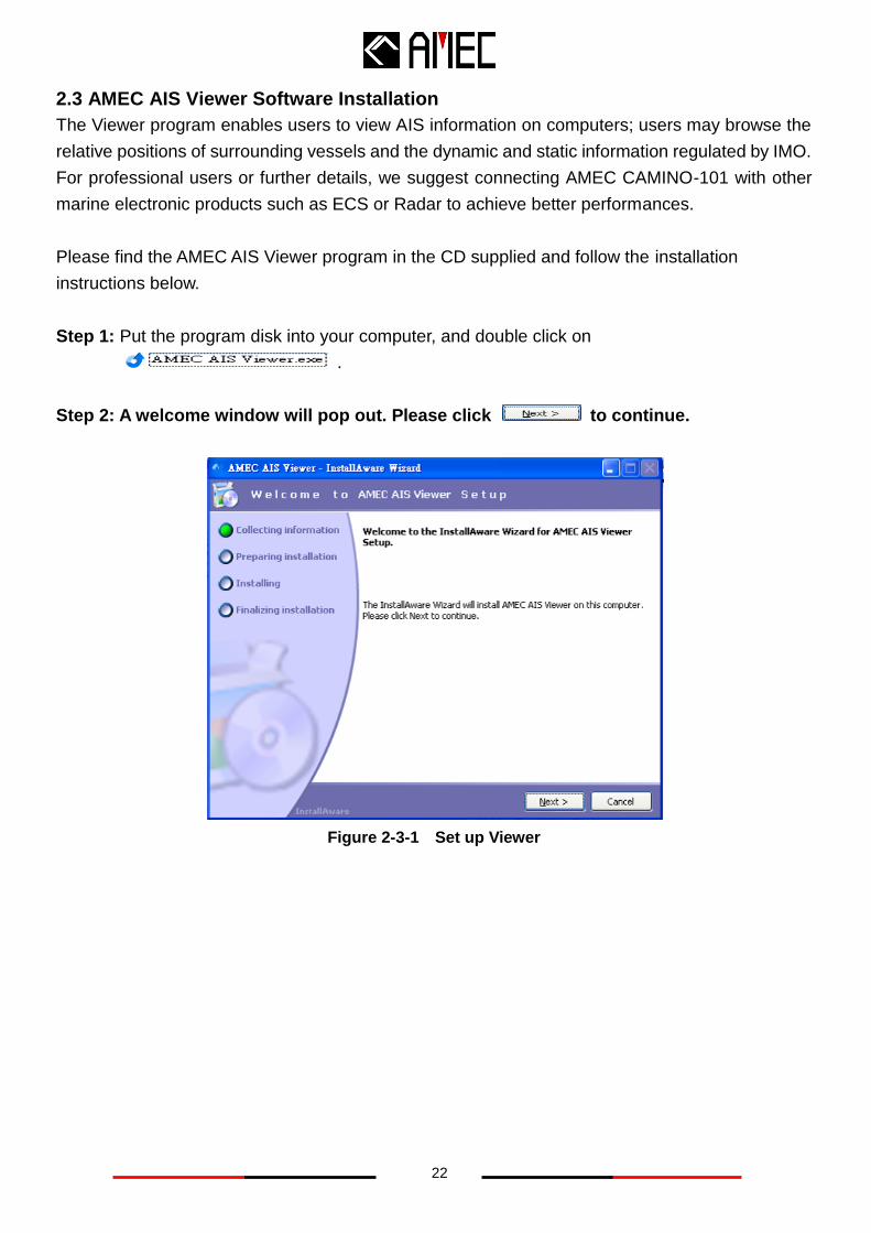
2.3 AMEC AIS Viewer Software Installation
The Viewer program enables users to view AIS information on computers; users may browse the
relative positions of surrounding vessels and the dynamic and static information regulated by IMO.
For professional users or further details, we suggest connecting AMEC CAMINO-101 with other
marine electronic products such as ECS or Radar to achieve better performances.
Please find the AMEC AIS Viewer program in the CD supplied and follow the installation
instructions below.
Step 1: Put the program disk into your computer, and double click on
.
Step 2: A welcome window will pop out. Please click to continue.
Figure 2-3-1 Set up Viewer
23
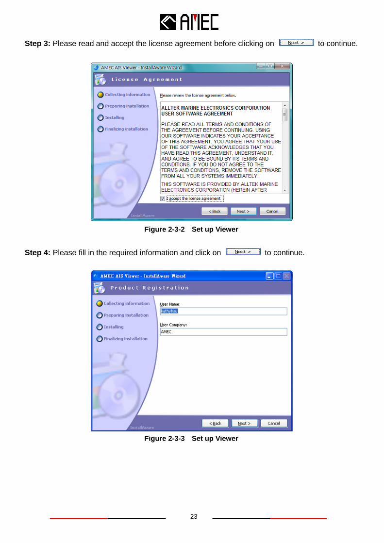
Step 3: Please read and accept the license agreement before clicking on to continue.
Figure 2-3-2 Set up Viewer
Step 4: Please fill in the required information and click on to continue.
Figure 2-3-3 Set up Viewer
24
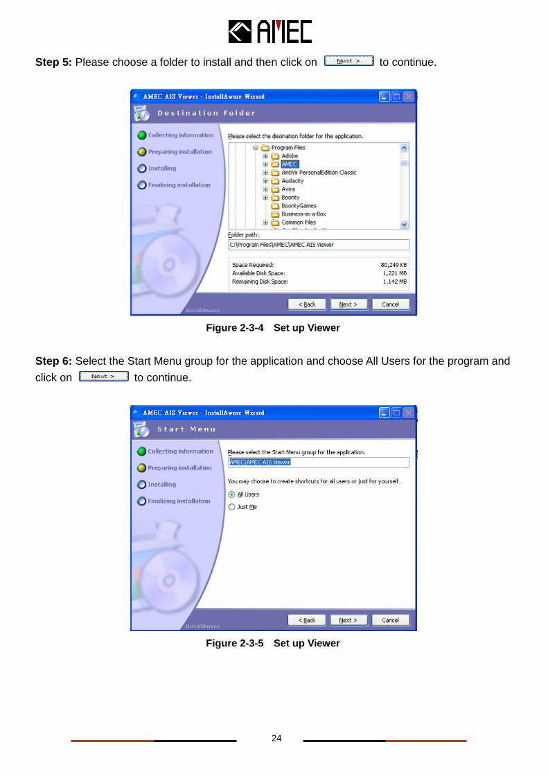
Step 5: Please choose a folder to install and then click on to continue.
Figure 2-3-4 Set up Viewer
Step 6: Select the Start Menu group for the application and choose All Users for the program and
click on to continue.
Figure 2-3-5 Set up Viewer
25
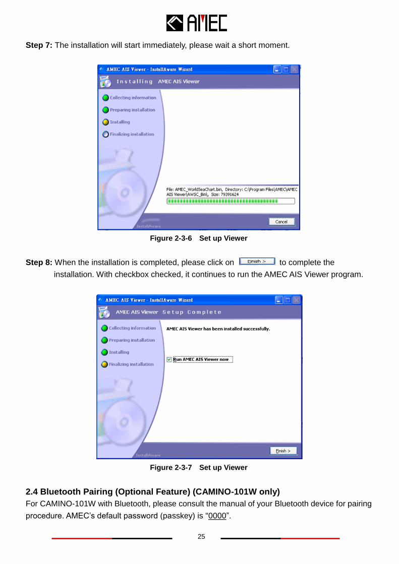
Step 7: The installation will start immediately, please wait a short moment.
Figure 2-3-6 Set up Viewer
Step 8: When the installation is completed, please click on to complete the
installation. With checkbox checked, it continues to run the AMEC AIS Viewer program.
Figure 2-3-7 Set up Viewer
2.4 Bluetooth Pairing (Optional Feature) (CAMINO-101W only)
For CAMINO-101W with Bluetooth, please consult the manual of your Bluetooth device for pairing
procedure. AMEC’s default password (passkey) is "0000”.
26
3 GET STARTED
3.1 Turning Power ON / OFF
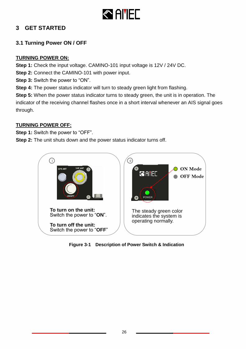
TURNING POWER ON:
Step 1: Check the input voltage. CAMINO-101 input voltage is 12V / 24V DC.
Step 2: Connect the CAMINO-101 with power input.
Step 3: Switch the power to “ON”.
Step 4: The power status indicator will turn to steady green light from flashing.
Step 5: When the power status indicator turns to steady green, the unit is in operation. The
indicator of the receiving channel flashes once in a short interval whenever an AIS signal goes
through.
TURNING POWER OFF:
Step 1: Switch the power to “OFF”.
Step 2: The unit shuts down and the power status indicator turns off.
Figure 3-1 Description of Power Switch & Indication
Light
To turn on the unit: Switch the power to “ON”. To turn off the unit: Switch the power to “OFF”
1 2
The steady green color indicates the system is operating normally.
ON Mode
OFF Mode
27
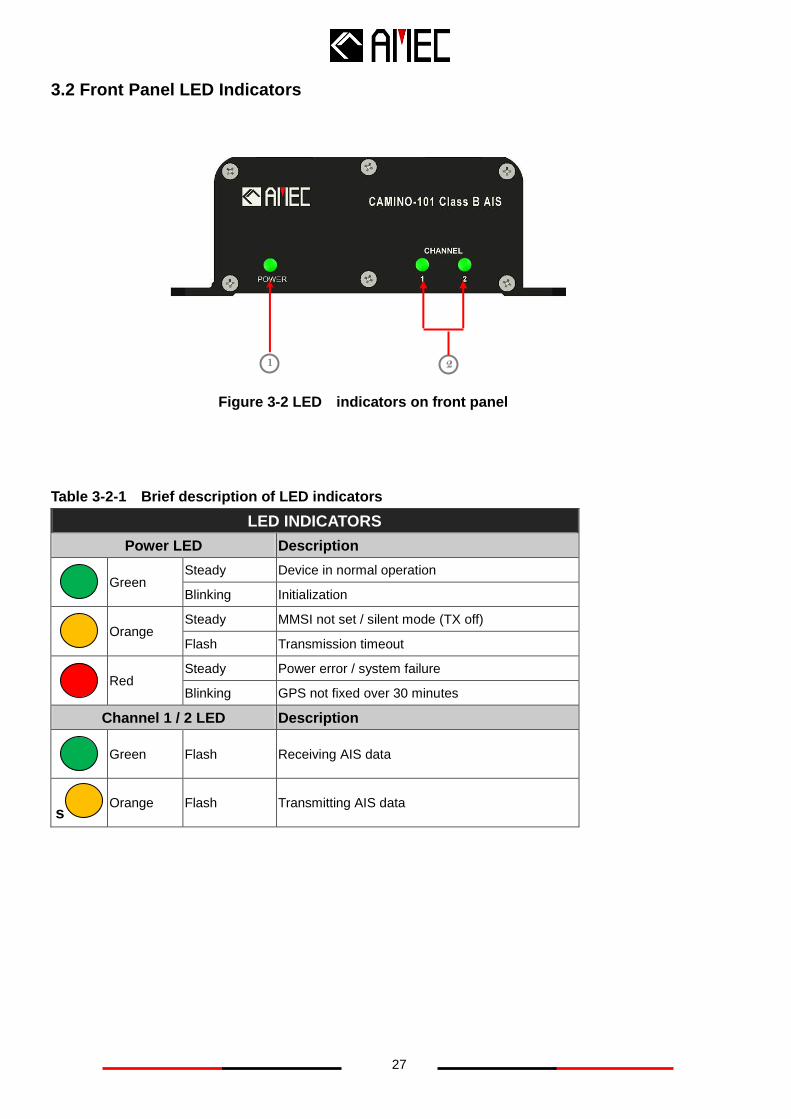
3.2 Front Panel LED Indicators
Table 3-2-1 Brief description of LED indicators
LED INDICATORS
Power LED Description
Green
Steady Device in normal operation
Blinking Initialization
Orange
Steady MMSI not set / silent mode (TX off)
Flash Transmission timeout
Red
Steady Power error / system failure
Blinking GPS not fixed over 30 minutes
Channel 1 / 2 LED Description
Green Flash Receiving AIS data
s Orange Flash Transmitting AIS data
Figure 3-2 LED indicators on front panel
1 2
28
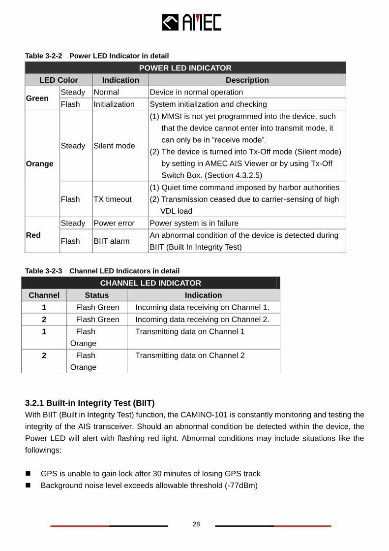
Table 3-2-2 Power LED Indicator in detail
POWER LED INDICATOR
LED Color Indication Description
Green Steady Normal Device in normal operation
Flash Initialization System initialization and checking
Orange
Steady Silent mode
(1) MMSI is not yet programmed into the device, such
that the device cannot enter into transmit mode, it
can only be in “receive mode”.
(2) The device is turned into Tx-Off mode (Silent mode)
by setting in AMEC AIS Viewer or by using Tx-Off
Switch Box. (Section 4.3.2.5)
Flash TX timeout
(1) Quiet time command imposed by harbor authorities
(2) Transmission ceased due to carrier-sensing of high
VDL load
Red
Steady Power error Power system is in failure
Flash BIIT alarm An abnormal condition of the device is detected during
BIIT (Built In Integrity Test)
Table 3-2-3 Channel LED Indicators in detail
CHANNEL LED INDICATOR
Channel Status Indication
1 Flash Green Incoming data receiving on Channel 1.
2 Flash Green Incoming data receiving on Channel 2.
1 Flash
Orange
Transmitting data on Channel 1
2 Flash
Orange
Transmitting data on Channel 2
3.2.1 Built-in Integrity Test (BIIT)
With BIIT (Built in Integrity Test) function, the CAMINO-101 is constantly monitoring and testing the
integrity of the AIS transceiver. Should an abnormal condition be detected within the device, the
Power LED will alert with flashing red light. Abnormal conditions may include situations like the
followings:
GPS is unable to gain lock after 30 minutes of losing GPS track
Background noise level exceeds allowable threshold (-77dBm)
29
3.3 CAMINO-101 Configuration Settings
To configure CAMINO-101, use the AMEC AIS Configuration software in the provided CD-ROM.
The software has both configuration and diagnostic functions. Beware that MMSI setting is
mandatory for CAMINO-101’s operation.
3.3.1 Configuration Settings
The following steps (step 1 ~ 4) describe the details of configuration settings:
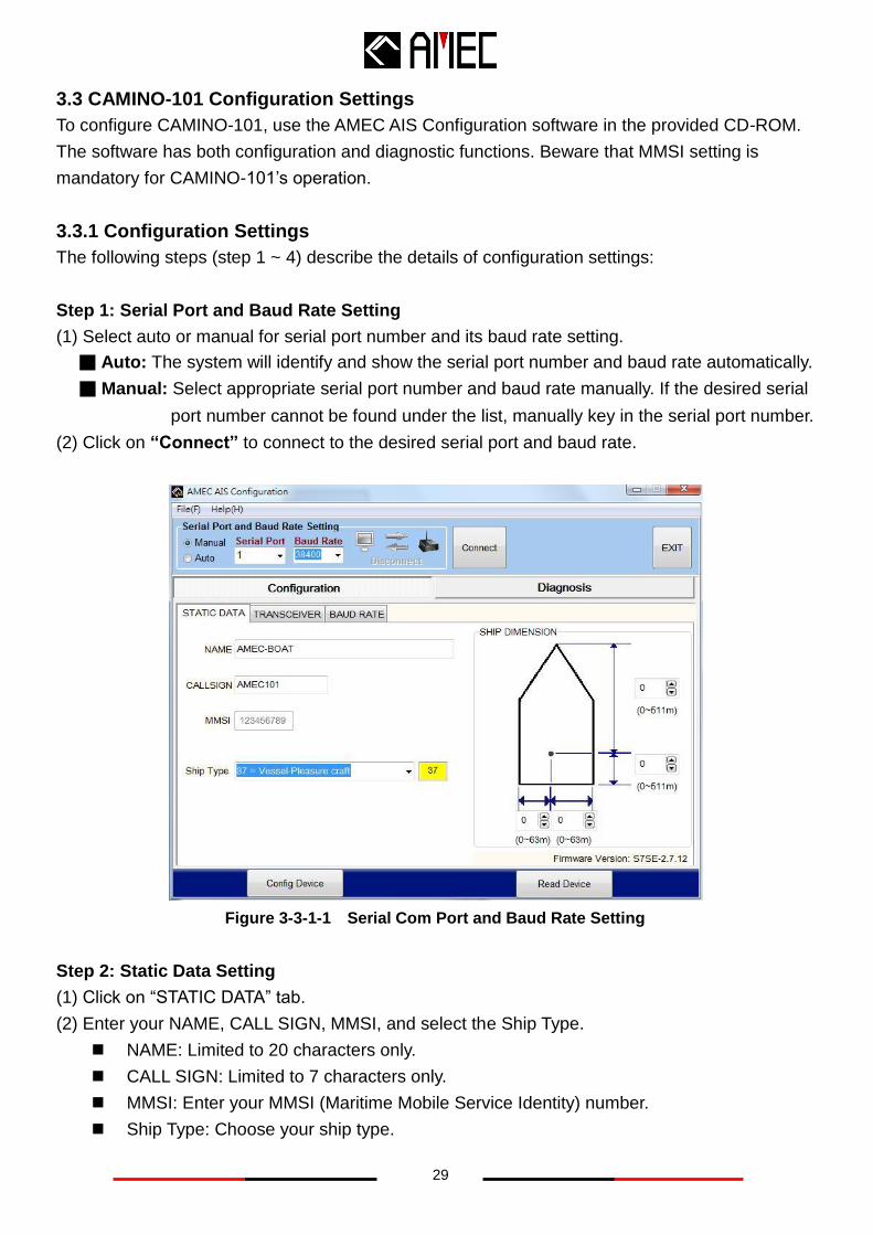
Step 1: Serial Port and Baud Rate Setting
(1) Select auto or manual for serial port number and its baud rate setting.
■ Auto: The system will identify and show the serial port number and baud rate automatically.
■ Manual: Select appropriate serial port number and baud rate manually. If the desired serial
port number cannot be found under the list, manually key in the serial port number.
(2) Click on “Connect” to connect to the desired serial port and baud rate.
Figure 3-3-1-1 Serial Com Port and Baud Rate Setting
Step 2: Static Data Setting
(1) Click on “STATIC DATA” tab.
(2) Enter your NAME, CALL SIGN, MMSI, and select the Ship Type.
NAME: Limited to 20 characters only.
CALL SIGN: Limited to 7 characters only.
MMSI: Enter your MMSI (Maritime Mobile Service Identity) number.
Ship Type: Choose your ship type.
30
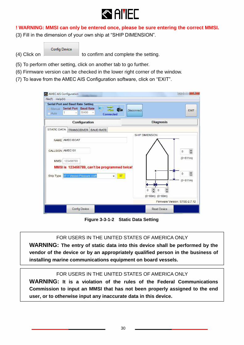
! WARNING: MMSI can only be entered once, please be sure entering the correct MMSI.
(3) Fill in the dimension of your own ship at “SHIP DIMENSION”.
(4) Click on to confirm and complete the setting.
(5) To perform other setting, click on another tab to go further.
(6) Firmware version can be checked in the lower right corner of the window.
(7) To leave from the AMEC AIS Configuration software, click on “EXIT”.
Figure 3-3-1-2 Static Data Setting
FOR USERS IN THE UNITED STATES OF AMERICA ONLY
WARNING: The entry of static data into this device shall be performed by the
vendor of the device or by an appropriately qualified person in the business of
installing marine communications equipment on board vessels.
FOR USERS IN THE UNITED STATES OF AMERICA ONLY
WARNING: It is a violation of the rules of the Federal Communications
Commission to input an MMSI that has not been properly assigned to the end
user, or to otherwise input any inaccurate data in this device.
31
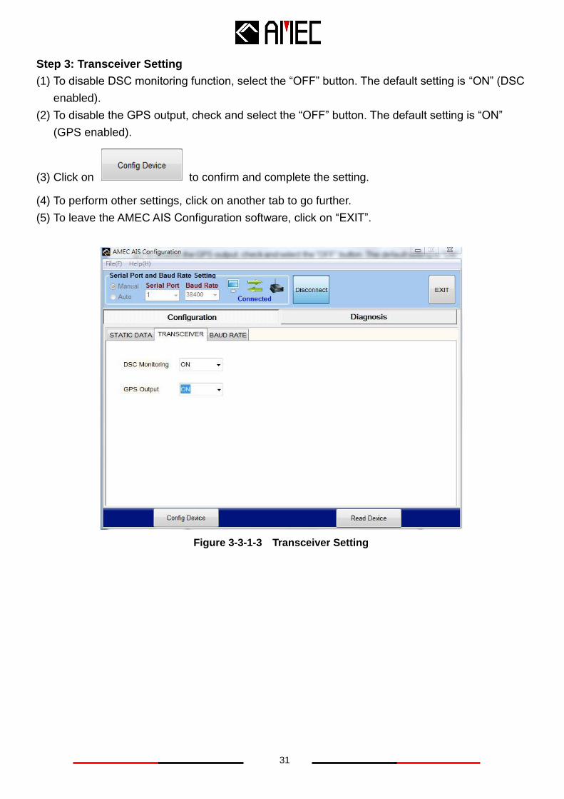
Step 3: Transceiver Setting
(1) To disable DSC monitoring function, select the “OFF” button. The default setting is “ON” (DSC
enabled).
(2) To disable the GPS output, check and select the “OFF” button. The default setting is “ON”
(GPS enabled).
(3) Click on to confirm and complete the setting.
(4) To perform other settings, click on another tab to go further.
(5) To leave the AMEC AIS Configuration software, click on “EXIT”.
Figure 3-3-1-3 Transceiver Setting
32
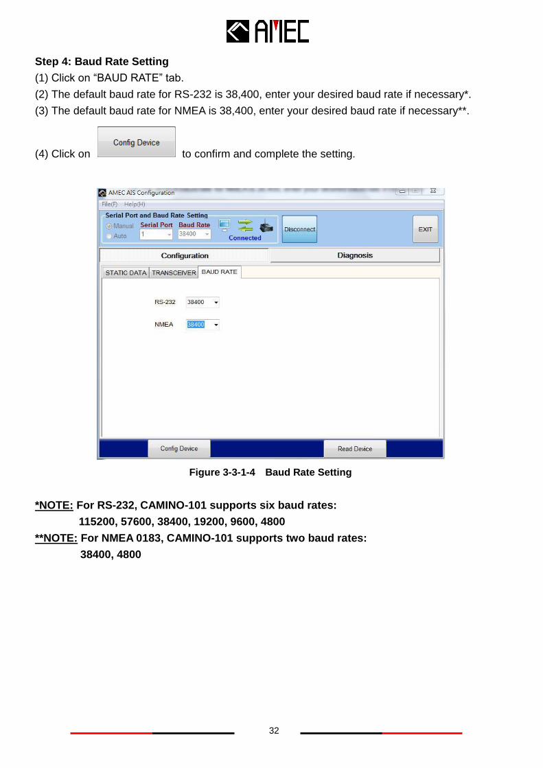
Step 4: Baud Rate Setting
(1) Click on “BAUD RATE” tab.
(2) The default baud rate for RS-232 is 38,400, enter your desired baud rate if necessary*.
(3) The default baud rate for NMEA is 38,400, enter your desired baud rate if necessary**.
(4) Click on to confirm and complete the setting.
Figure 3-3-1-4 Baud Rate Setting
*NOTE: For RS-232, CAMINO-101 supports six baud rates:
115200, 57600, 38400, 19200, 9600, 4800
**NOTE: For NMEA 0183, CAMINO-101 supports two baud rates:
38400, 4800
33
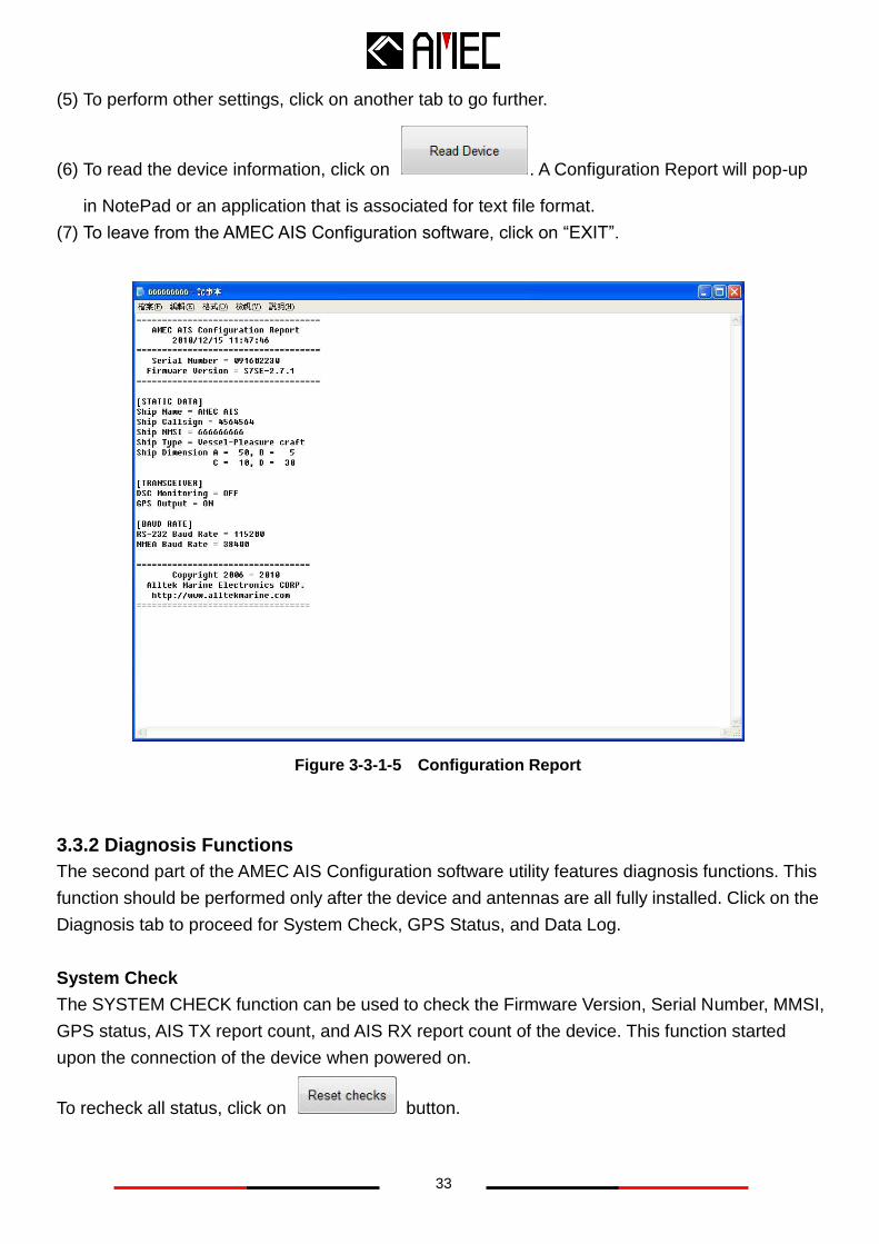
(5) To perform other settings, click on another tab to go further.
(6) To read the device information, click on . A Configuration Report will pop-up
in NotePad or an application that is associated for text file format.
(7) To leave from the AMEC AIS Configuration software, click on “EXIT”.
Figure 3-3-1-5 Configuration Report
3.3.2 Diagnosis Functions
The second part of the AMEC AIS Configuration software utility features diagnosis functions. This
function should be performed only after the device and antennas are all fully installed. Click on the
Diagnosis tab to proceed for System Check, GPS Status, and Data Log.
System Check
The SYSTEM CHECK function can be used to check the Firmware Version, Serial Number, MMSI,
GPS status, AIS TX report count, and AIS RX report count of the device. This function started
upon the connection of the device when powered on.
To recheck all status, click on button.
34
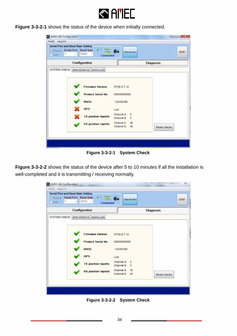
Figure 3-3-2-1 shows the status of the device when initially connected.
Figure 3-3-2-1 System Check
Figure 3-3-2-2 shows the status of the device after 5 to 10 minutes if all the installation is
well-completed and it is transmitting / receiving normally.
Figure 3-3-2-2 System Check
35
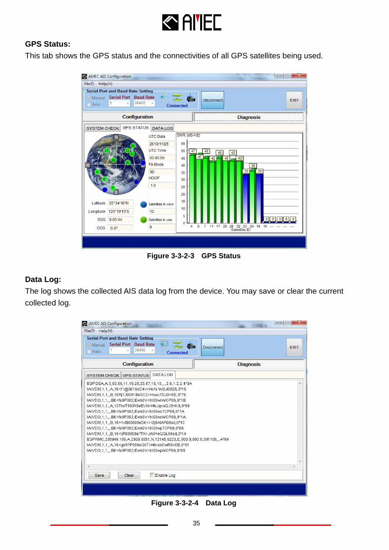
GPS Status:
This tab shows the GPS status and the connectivities of all GPS satellites being used.
Figure 3-3-2-3 GPS Status
Data Log:
The log shows the collected AIS data log from the device. You may save or clear the current
collected log.
Figure 3-3-2-4 Data Log
36
4 AMEC AIS VIEWER DESCRIPTION
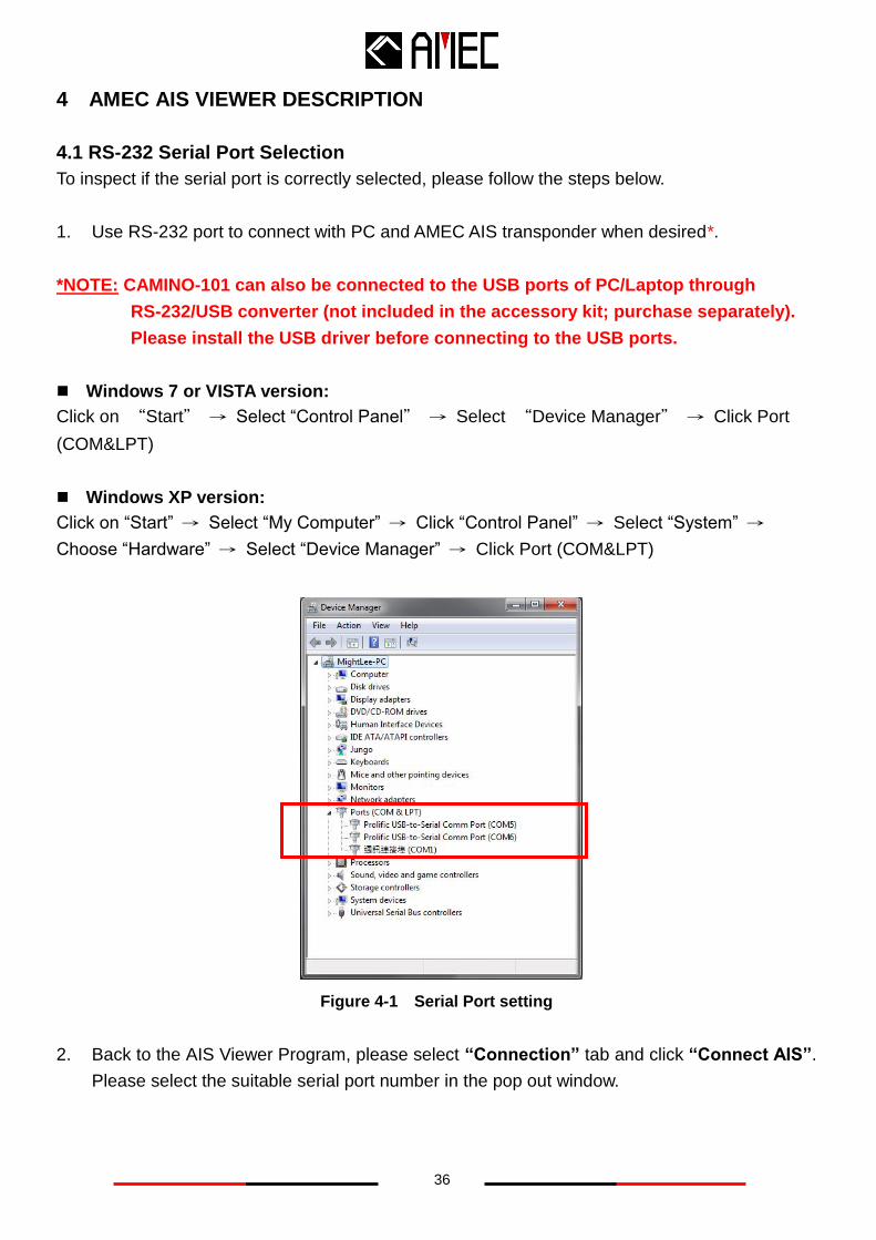
4.1 RS-232 Serial Port Selection
To inspect if the serial port is correctly selected, please follow the steps below.
1. Use RS-232 port to connect with PC and AMEC AIS transponder when desired*.
*NOTE: CAMINO-101 can also be connected to the USB ports of PC/Laptop through
RS-232/USB converter (not included in the accessory kit; purchase separately).
Please install the USB driver before connecting to the USB ports.
Windows 7 or VISTA version:
Click on “Start” → Select “Control Panel” → Select “Device Manager” → Click Port
(COM&LPT)
Windows XP version:
Click on “Start” → Select “My Computer” → Click “Control Panel” → Select “System” →
Choose “Hardware” → Select “Device Manager” → Click Port (COM&LPT)
Figure 4-1 Serial Port setting
2. Back to the AIS Viewer Program, please select “Connection” tab and click “Connect AIS”.
Please select the suitable serial port number in the pop out window.
37
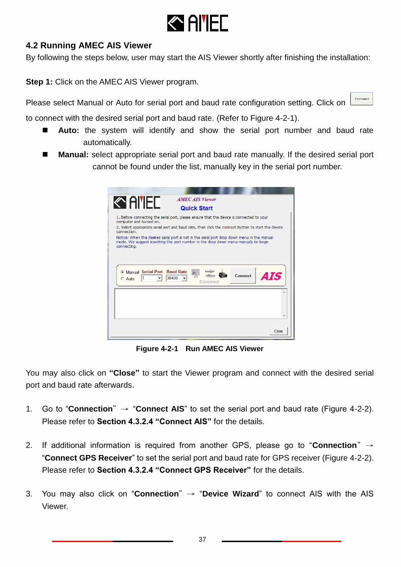
4.2 Running AMEC AIS Viewer
By following the steps below, user may start the AIS Viewer shortly after finishing the installation:
Step 1: Click on the AMEC AIS Viewer program.
Please select Manual or Auto for serial port and baud rate configuration setting. Click on
to connect with the desired serial port and baud rate. (Refer to Figure 4-2-1).
Auto: the system will identify and show the serial port number and baud rate
automatically.
Manual: select appropriate serial port and baud rate manually. If the desired serial port
cannot be found under the list, manually key in the serial port number.
Figure 4-2-1 Run AMEC AIS Viewer
You may also click on “Close” to start the Viewer program and connect with the desired serial
port and baud rate afterwards.
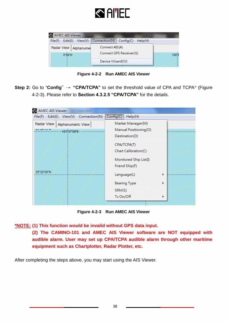
1. Go to “Connection”→ “Connect AIS” to set the serial port and baud rate (Figure 4-2-2).
Please refer to Section 4.3.2.4 “Connect AIS” for the details.
2. If additional information is required from another GPS, please go to “Connection”→
“Connect GPS Receiver” to set the serial port and baud rate for GPS receiver (Figure 4-2-2).
Please refer to Section 4.3.2.4 “Connect GPS Receiver” for the details.
3. You may also click on “Connection”→ “Device Wizard” to connect AIS with the AIS
Viewer.
38
Figure 4-2-2 Run AMEC AIS Viewer
Step 2: Go to “Config”→ “CPA/TCPA” to set the threshold value of CPA and TCPA* (Figure
4-2-3). Please refer to Section 4.3.2.5 “CPA/TCPA” for the details.
Figure 4-2-3 Run AMEC AIS Viewer
*NOTE: (1) This function would be invalid without GPS data input.
(2) The CAMINO-101 and AMEC AIS Viewer software are NOT equipped with
audible alarm. User may set up CPA/TCPA audible alarm through other maritime
equipment such as Chartplotter, Radar Plotter, etc.
After completing the steps above, you may start using the AIS Viewer.
39
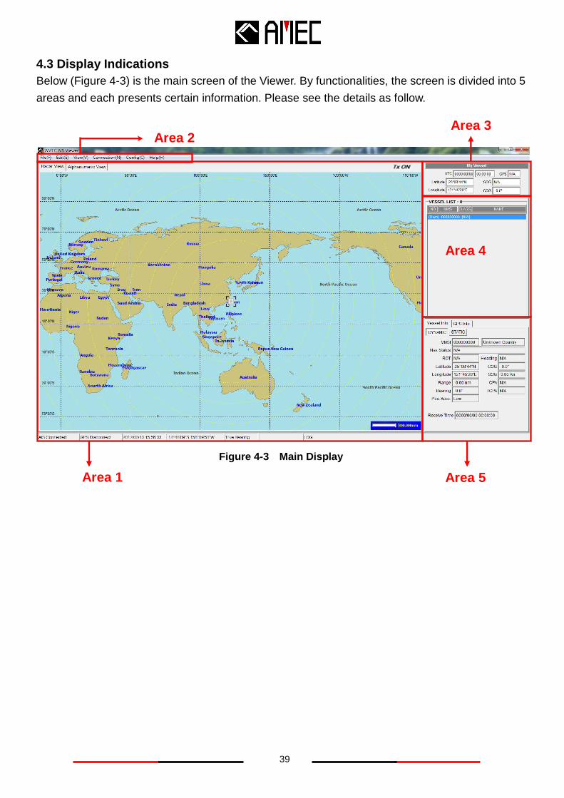
4.3 Display Indications
Below (Figure 4-3) is the main screen of the Viewer. By functionalities, the screen is divided into 5
areas and each presents certain information. Please see the details as follow.
Figure 4-3 Main Display
Area 3
Area 4
Area 2
Area 5 Area 1
40
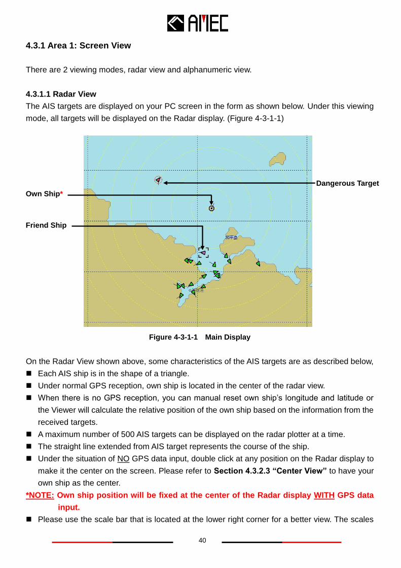
4.3.1 Area 1: Screen View
There are 2 viewing modes, radar view and alphanumeric view.
4.3.1.1 Radar View
The AIS targets are displayed on your PC screen in the form as shown below. Under this viewing
mode, all targets will be displayed on the Radar display. (Figure 4-3-1-1)
Figure 4-3-1-1 Main Display
On the Radar View shown above, some characteristics of the AIS targets are as described below,
Each AIS ship is in the shape of a triangle.
Under normal GPS reception, own ship is located in the center of the radar view.
When there is no GPS reception, you can manual reset own ship’s longitude and latitude or
the Viewer will calculate the relative position of the own ship based on the information from the
received targets.
A maximum number of 500 AIS targets can be displayed on the radar plotter at a time.
The straight line extended from AIS target represents the course of the ship.
Under the situation of NO GPS data input, double click at any position on the Radar display to
make it the center on the screen. Please refer to Section 4.3.2.3 “Center View” to have your
own ship as the center.
*NOTE: Own ship position will be fixed at the center of the Radar display WITH GPS data
input.
Please use the scale bar that is located at the lower right corner for a better view. The scales
Own Ship*
Dangerous Target
Friend Ship
41
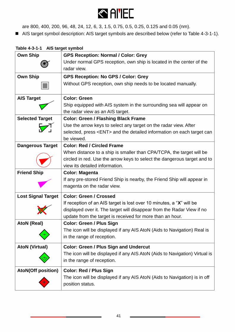
are 800, 400, 200, 96, 48, 24, 12, 6, 3, 1.5, 0.75, 0.5, 0.25, 0.125 and 0.05 (nm).
AIS target symbol description: AIS target symbols are described below (refer to Table 4-3-1-1).
Own Ship
GPS Reception: Normal / Color: Grey
Under normal GPS reception, own ship is located in the center of the
radar view.
Own Ship
GPS Reception: No GPS / Color: Grey
Without GPS reception, own ship needs to be located manually.
AIS Target
Color: Green
Ship equipped with AIS system in the surrounding sea will appear on
the radar view as an AIS target.
Selected Target
Color: Green / Flashing Black Frame
Use the arrow keys to select any target on the radar view. After
selected, press <ENT> and the detailed information on each target can
be viewed.
Dangerous Target
Color: Red / Circled Frame
When distance to a ship is smaller than CPA/TCPA, the target will be
circled in red. Use the arrow keys to select the dangerous target and to
view its detailed information.
Friend Ship
Color: Magenta
If any pre-stored Friend Ship is nearby, the Friend Ship will appear in
magenta on the radar view.
Lost Signal Target Color: Green / Crossed
If reception of an AIS target is lost over 10 minutes, a “X” will be
displayed over it. The target will disappear from the Radar View if no
update from the target is received for more than an hour.
AtoN (Real)
Color: Green / Plus Sign
The icon will be displayed if any AIS AtoN (Aids to Navigation) Real is
in the range of reception.
AtoN (Virtual)
Color: Green / Plus Sign and Undercut
The icon will be displayed if any AIS AtoN (Aids to Navigation) Virtual is
in the range of reception.
AtoN(Off position)
Color: Red / Plus Sign
The icon will be displayed if any AIS AtoN (Aids to Navigation) is in off
position status.
Table 4-3-1-1 AIS target symbol
42
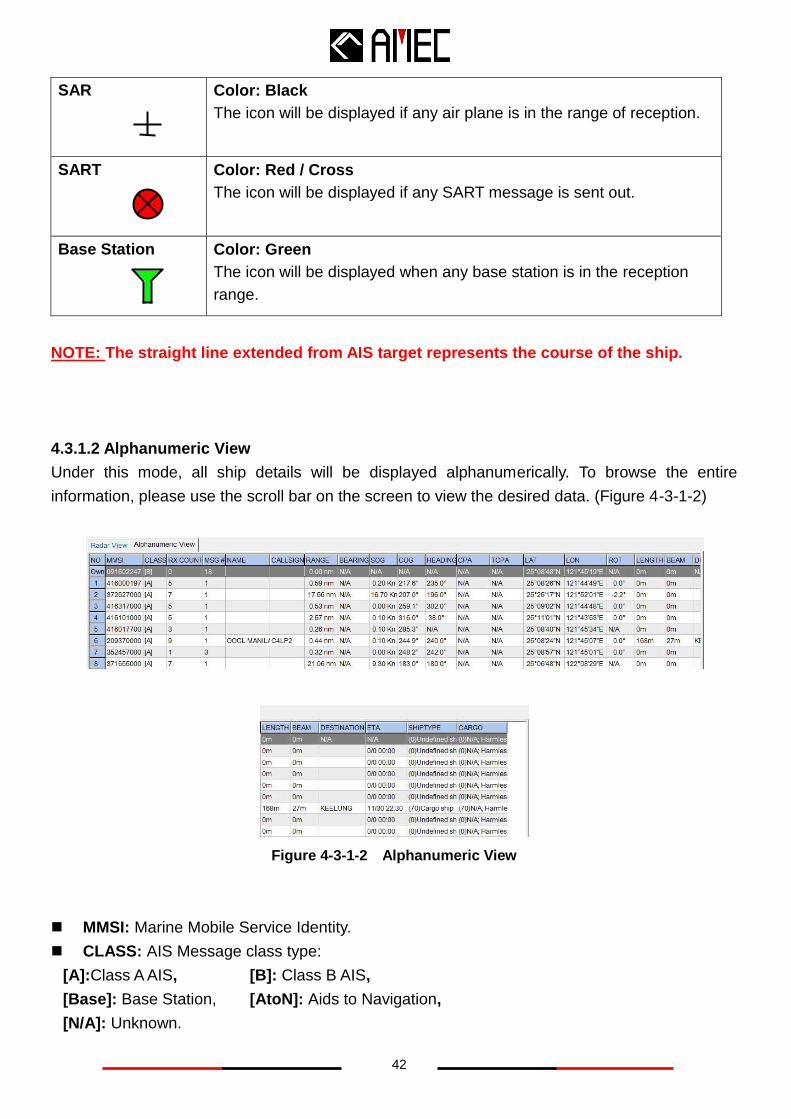
SAR
Color: Black
The icon will be displayed if any air plane is in the range of reception.
SART
Color: Red / Cross
The icon will be displayed if any SART message is sent out.
Base Station
Color: Green
The icon will be displayed when any base station is in the reception
range.
NOTE: The straight line extended from AIS target represents the course of the ship.
4.3.1.2 Alphanumeric View
Under this mode, all ship details will be displayed alphanumerically. To browse the entire
information, please use the scroll bar on the screen to view the desired data. (Figure 4-3-1-2)
Figure 4-3-1-2 Alphanumeric View
MMSI: Marine Mobile Service Identity.
CLASS: AIS Message class type:
[A]:Class A AIS, [B]: Class B AIS,
[Base]: Base Station, [AtoN]: Aids to Navigation,
[N/A]: Unknown.
43
RX COUNT: The numbers of receiving messages.
MSG # : The message ID should identify the message type.
NAME: Ship Name.
CALL SIGN: Ship’s Call Sign.
RANGE: The distance between target ships to own ship. The unit of range is “nm” (Nautical
Mile).
BEARING: The relative angle between target ship and own ship.
SOG: Speed Over Ground, the unit of SOG is “kn” (knot).
COG: Course Over Ground.
HEADING: The heading of the target ship.
CPA: Distance to Closest Point of Approach, the unit of CPA is “nm” (Nautical Miles)
TCPA: Time to Closest Point of Approach, the unit of TCPA is “min” (Minutes).
LON: Longitude of the target ship.
LAT: Latitude of the target ship.
ROT: Rate Of Turn.
LENGTH: The length of the target ship, the unit of LENGTH is “m” (meters).
BEAM: The beam of the target ship, the unit of BEAM is “m” (meters).
DESTINATION: The destination of the target ship.
ETA: Estimated Time of Arrival, (Month/Date/Hour/Minutes)
SHIPTYPE: Ship type of the target ship.
CARGO: Cargo information.
44
4.3.2 Area 2: Main Menu
This area contains the main menu bar of the AIS Viewer.
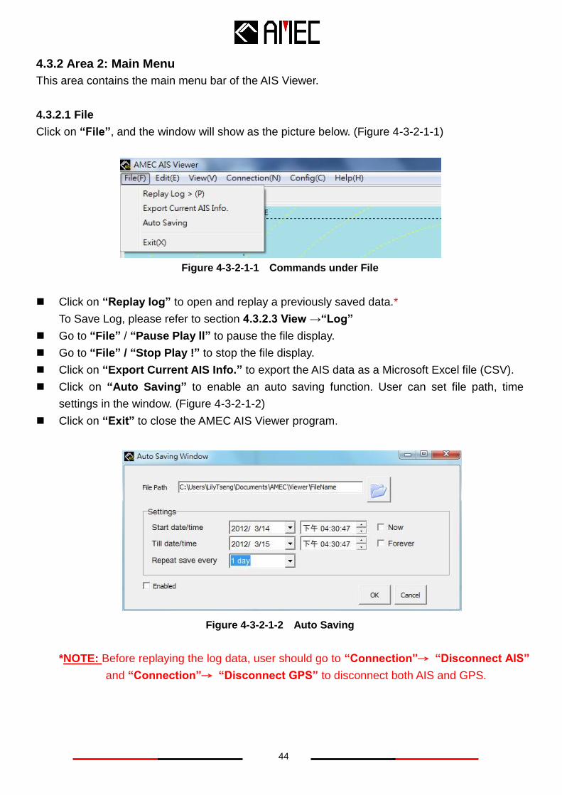
4.3.2.1 File
Click on “File”, and the window will show as the picture below. (Figure 4-3-2-1-1)
Figure 4-3-2-1-1 Commands under File
Click on “Replay log” to open and replay a previously saved data.*
To Save Log, please refer to section 4.3.2.3 View →“Log”
Go to “File” / “Pause Play ll” to pause the file display.
Go to “File” / “Stop Play !” to stop the file display.
Click on “Export Current AIS Info.” to export the AIS data as a Microsoft Excel file (CSV).
Click on “Auto Saving” to enable an auto saving function. User can set file path, time
settings in the window. (Figure 4-3-2-1-2)
Click on “Exit” to close the AMEC AIS Viewer program.
Figure 4-3-2-1-2 Auto Saving
*NOTE: Before replaying the log data, user should go to “Connection”→ “Disconnect AIS”
and “Connection”→ “Disconnect GPS” to disconnect both AIS and GPS.
45
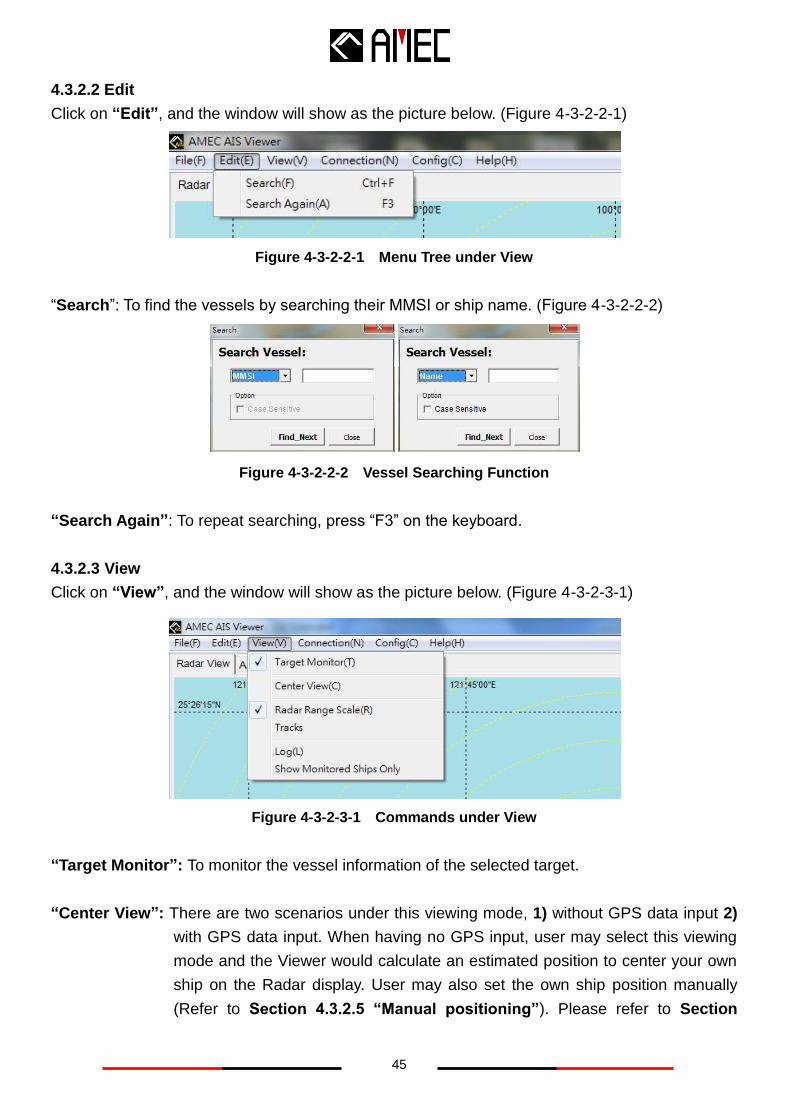
4.3.2.2 Edit
Click on “Edit”, and the window will show as the picture below. (Figure 4-3-2-2-1)
Figure 4-3-2-2-1 Menu Tree under View
“Search”: To find the vessels by searching their MMSI or ship name. (Figure 4-3-2-2-2)
Figure 4-3-2-2-2 Vessel Searching Function
“Search Again”: To repeat searching, press “F3” on the keyboard.
4.3.2.3 View
Click on “View”, and the window will show as the picture below. (Figure 4-3-2-3-1)
Figure 4-3-2-3-1 Commands under View
“Target Monitor”: To monitor the vessel information of the selected target.
“Center View”: There are two scenarios under this viewing mode, 1) without GPS data input 2)
with GPS data input. When having no GPS input, user may select this viewing
mode and the Viewer would calculate an estimated position to center your own
ship on the Radar display. User may also set the own ship position manually
(Refer to Section 4.3.2.5 “Manual positioning”). Please refer to Section
46
4.3.1.1 “Radar View” for more viewing options. With the availability of GPS
data input, the Viewer will set your own ship as the center on the Radar display
automatically and hence the “Center View” would be invalid.
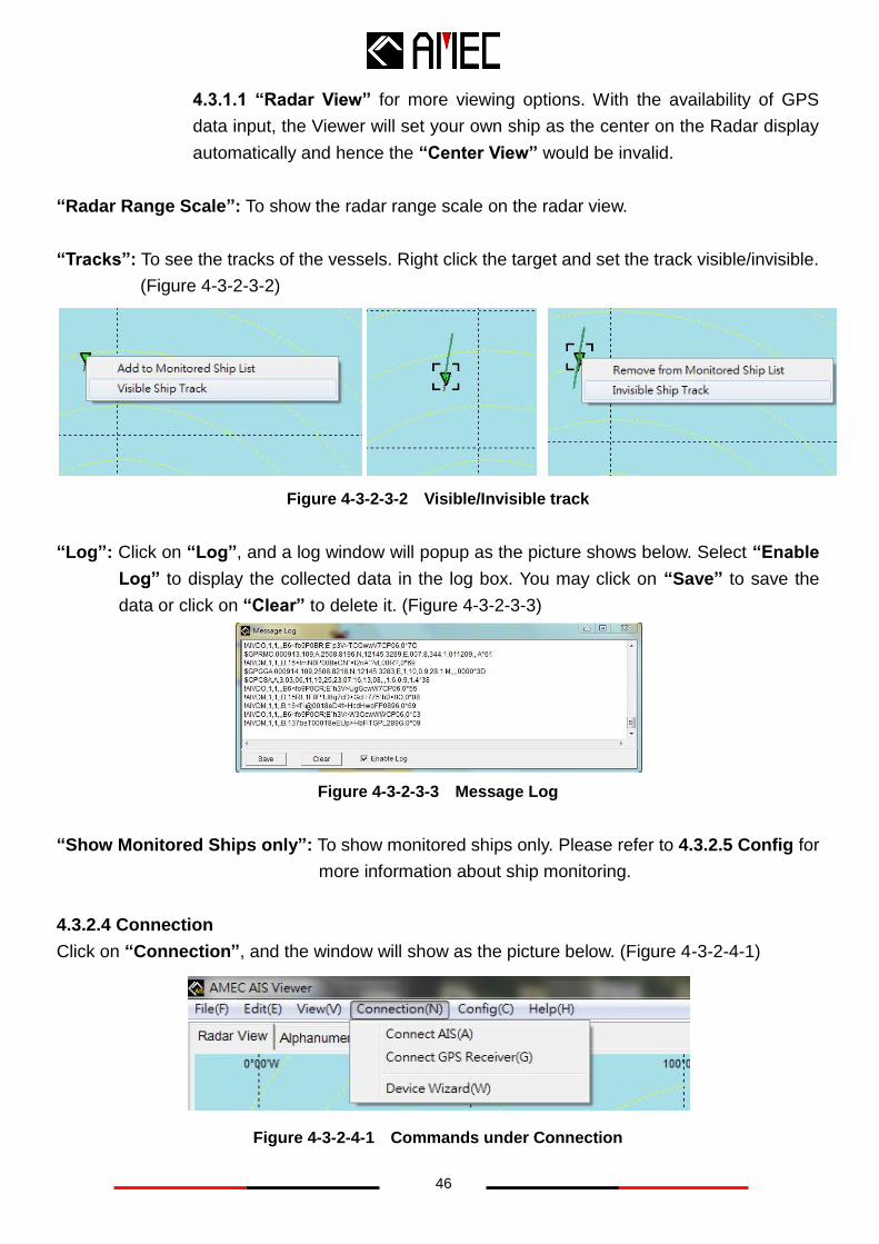
“Radar Range Scale”: To show the radar range scale on the radar view.
“Tracks”: To see the tracks of the vessels. Right click the target and set the track visible/invisible.
(Figure 4-3-2-3-2)
Figure 4-3-2-3-2 Visible/Invisible track
“Log”: Click on “Log”, and a log window will popup as the picture shows below. Select “Enable
Log” to display the collected data in the log box. You may click on “Save” to save the
data or click on “Clear” to delete it. (Figure 4-3-2-3-3)
Figure 4-3-2-3-3 Message Log
“Show Monitored Ships only”: To show monitored ships only. Please refer to 4.3.2.5 Config for
more information about ship monitoring.
4.3.2.4 Connection
Click on “Connection”, and the window will show as the picture below. (Figure 4-3-2-4-1)
Figure 4-3-2-4-1 Commands under Connection
47
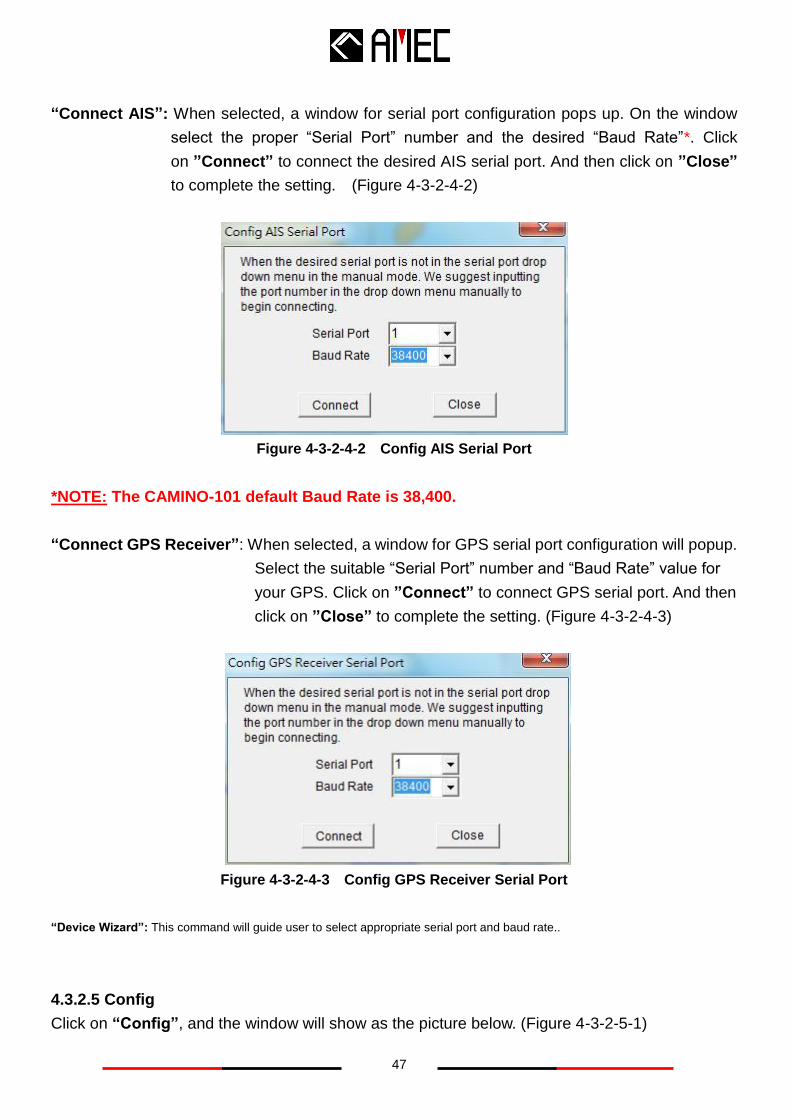
“Connect AIS”: When selected, a window for serial port configuration pops up. On the window
select the proper “Serial Port” number and the desired “Baud Rate”*. Click
on ”Connect” to connect the desired AIS serial port. And then click on ”Close”
to complete the setting. (Figure 4-3-2-4-2)
Figure 4-3-2-4-2 Config AIS Serial Port
*NOTE: The CAMINO-101 default Baud Rate is 38,400.
“Connect GPS Receiver”: When selected, a window for GPS serial port configuration will popup.
Select the suitable “Serial Port” number and “Baud Rate” value for
your GPS. Click on ”Connect” to connect GPS serial port. And then
click on ”Close” to complete the setting. (Figure 4-3-2-4-3)
Figure 4-3-2-4-3 Config GPS Receiver Serial Port
“Device Wizard”: This command will guide user to select appropriate serial port and baud rate..
4.3.2.5 Config
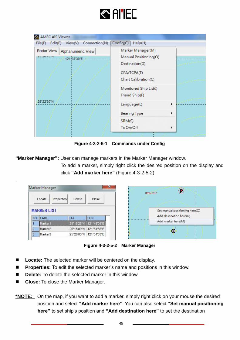
Click on “Config”, and the window will show as the picture below. (Figure 4-3-2-5-1)
48
Figure 4-3-2-5-1 Commands under Config
“Marker Manager”: User can manage markers in the Marker Manager window.
To add a marker, simply right click the desired position on the display and
click “Add marker here” (Figure 4-3-2-5-2)
.
Figure 4-3-2-5-2 Marker Manager
Locate: The selected marker will be centered on the display.
Properties: To edit the selected marker’s name and positions in this window.
Delete: To delete the selected marker in this window.
Close: To close the Marker Manager.
*NOTE: On the map, if you want to add a marker, simply right click on your mouse the desired
position and select “Add marker here”. You can also select “Set manual positioning
here” to set ship’s position and “Add destination here” to set the destination
49
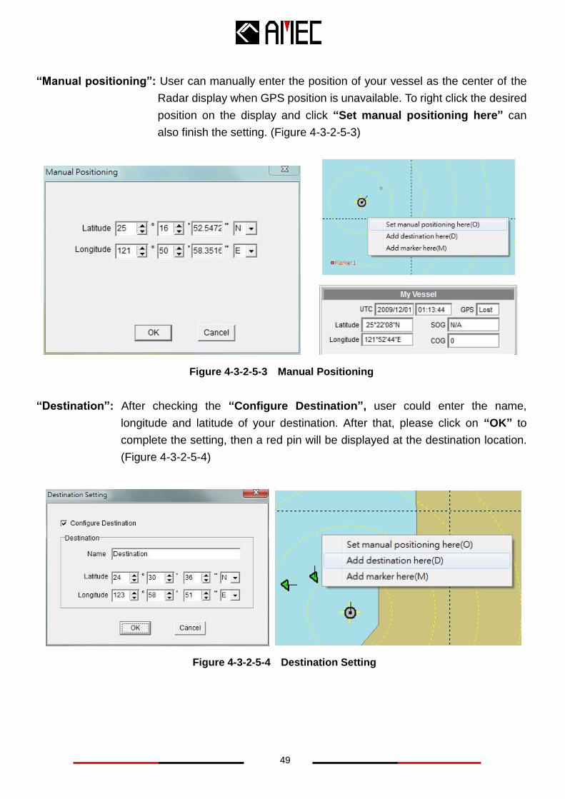
“Manual positioning”: User can manually enter the position of your vessel as the center of the
Radar display when GPS position is unavailable. To right click the desired
position on the display and click “Set manual positioning here” can
also finish the setting. (Figure 4-3-2-5-3)
Figure 4-3-2-5-3 Manual Positioning
“Destination”: After checking the “Configure Destination”, user could enter the name,
longitude and latitude of your destination. After that, please click on “OK” to
complete the setting, then a red pin will be displayed at the destination location.
(Figure 4-3-2-5-4)
Figure 4-3-2-5-4 Destination Setting
50
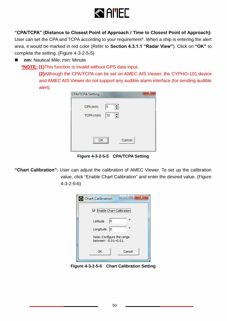
“CPA/TCPA” (Distance to Closest Point of Approach / Time to Closest Point of Approach):
User can set the CPA and TCPA according to your requirement*. When a ship is entering the alert
area, it would be marked in red color (Refer to Section 4.3.1.1 “Radar View”). Click on “OK” to
complete the setting. (Figure 4-3-2-5-5)
nm: Nautical Mile; min: Minute
*NOTE: (1)This function is invalid without GPS data input.
(2)Although the CPA/TCPA can be set on AMEC AIS Viewer, the CYPHO-101 device
and AMEC AIS Viewer do not support any audible alarm interface (for sending audible
alert).
Figure 4-3-2-5-5 CPA/TCPA Setting
“Chart Calibration”: User can adjust the calibration of AMEC Viewer. To set up the calibration
value, click “Enable Chart Calibration” and enter the desired value. (Figure
4-3-2-5-6)
Figure 4-3-2-5-6 Chart Calibration Setting
51
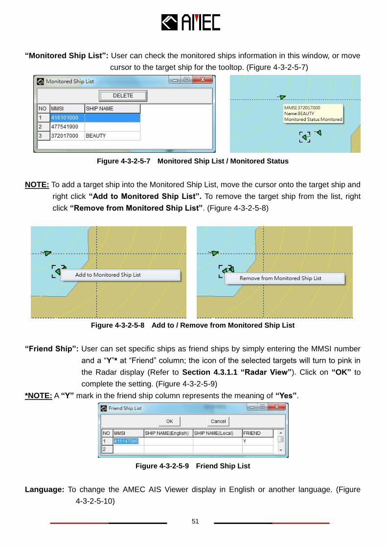
“Monitored Ship List”: User can check the monitored ships information in this window, or move
cursor to the target ship for the tooltop. (Figure 4-3-2-5-7)
Figure 4-3-2-5-7 Monitored Ship List / Monitored Status
NOTE: To add a target ship into the Monitored Ship List, move the cursor onto the target ship and
right click “Add to Monitored Ship List”. To remove the target ship from the list, right
click “Remove from Monitored Ship List”. (Figure 4-3-2-5-8)
Figure 4-3-2-5-8 Add to / Remove from Monitored Ship List
“Friend Ship”: User can set specific ships as friend ships by simply entering the MMSI number
and a “Y”* at “Friend” column; the icon of the selected targets will turn to pink in
the Radar display (Refer to Section 4.3.1.1 “Radar View”). Click on “OK” to
complete the setting. (Figure 4-3-2-5-9)
*NOTE: A “Y” mark in the friend ship column represents the meaning of “Yes”.
Figure 4-3-2-5-9 Friend Ship List
Language: To change the AMEC AIS Viewer display in English or another language. (Figure
4-3-2-5-10)
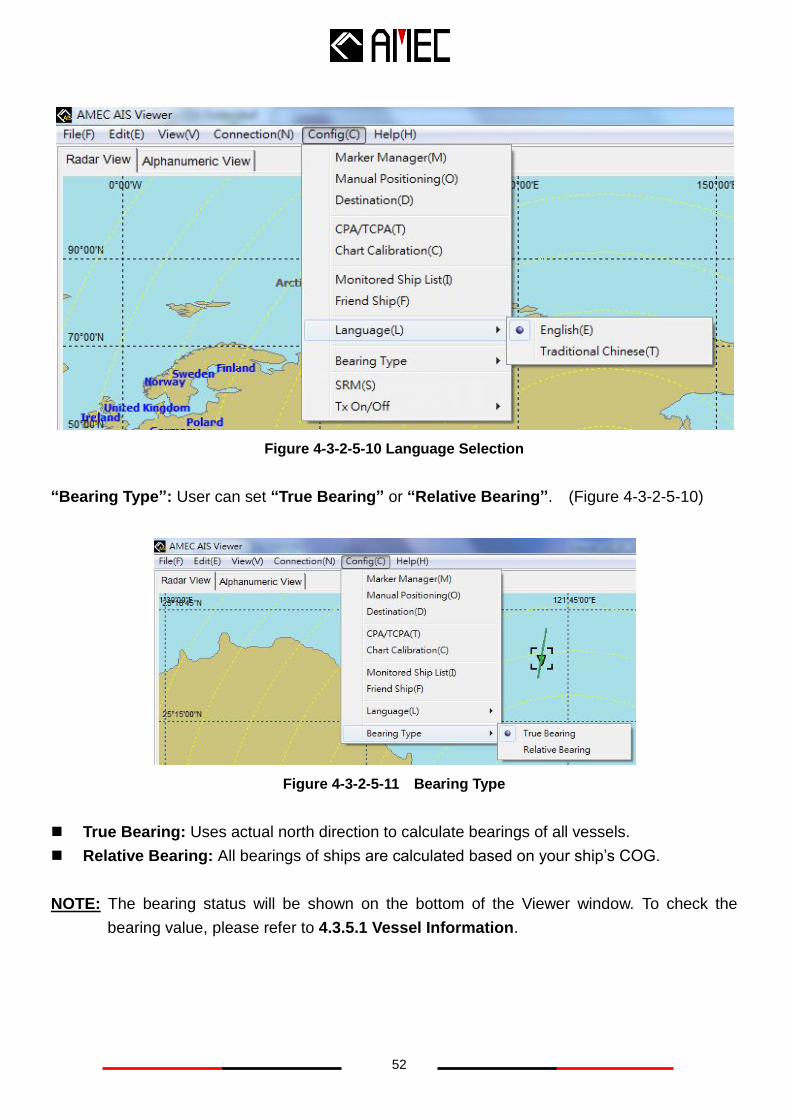
52
Figure 4-3-2-5-10 Language Selection
“Bearing Type”: User can set “True Bearing” or “Relative Bearing”. (Figure 4-3-2-5-10)
Figure 4-3-2-5-11 Bearing Type
True Bearing: Uses actual north direction to calculate bearings of all vessels.
Relative Bearing: All bearings of ships are calculated based on your ship’s COG.
NOTE: The bearing status will be shown on the bottom of the Viewer window. To check the
bearing value, please refer to 4.3.5.1 Vessel Information.
53
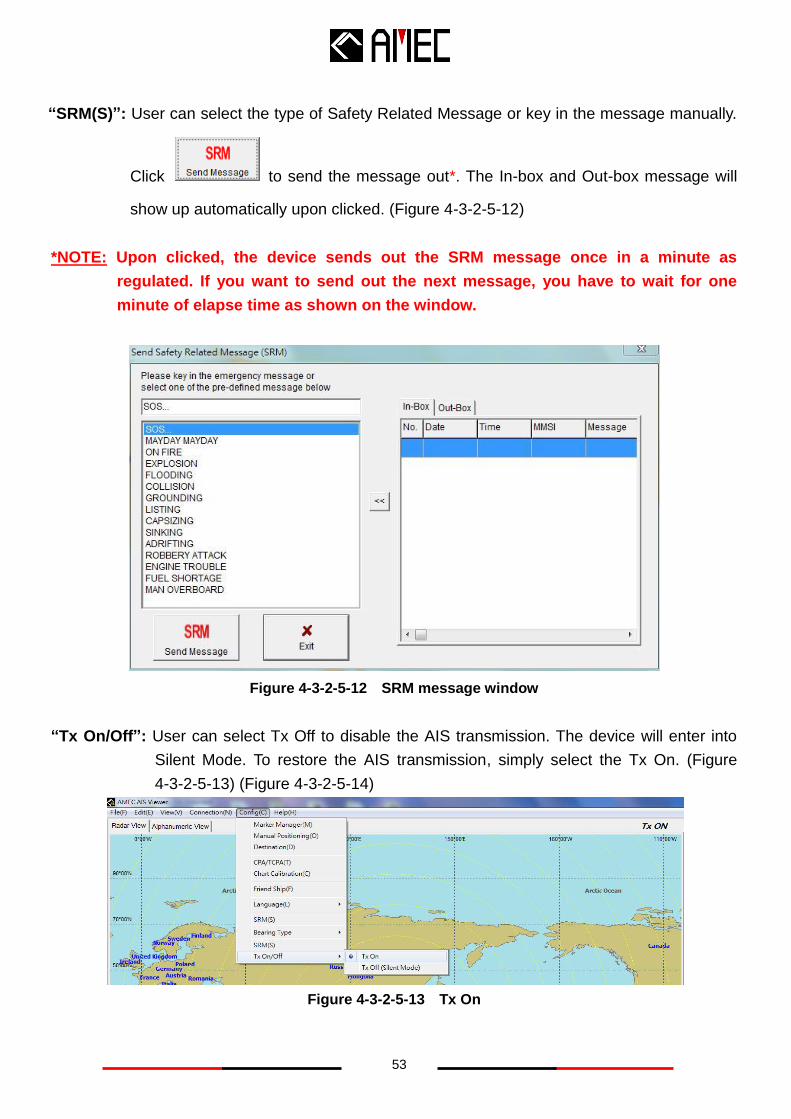
“SRM(S)”: User can select the type of Safety Related Message or key in the message manually.
Click to send the message out*. The In-box and Out-box message will
show up automatically upon clicked. (Figure 4-3-2-5-12)
*NOTE: Upon clicked, the device sends out the SRM message once in a minute as
regulated. If you want to send out the next message, you have to wait for one
minute of elapse time as shown on the window.
Figure 4-3-2-5-12 SRM message window
“Tx On/Off”: User can select Tx Off to disable the AIS transmission. The device will enter into
Silent Mode. To restore the AIS transmission, simply select the Tx On. (Figure
4-3-2-5-13) (Figure 4-3-2-5-14)
Figure 4-3-2-5-13 Tx On
54
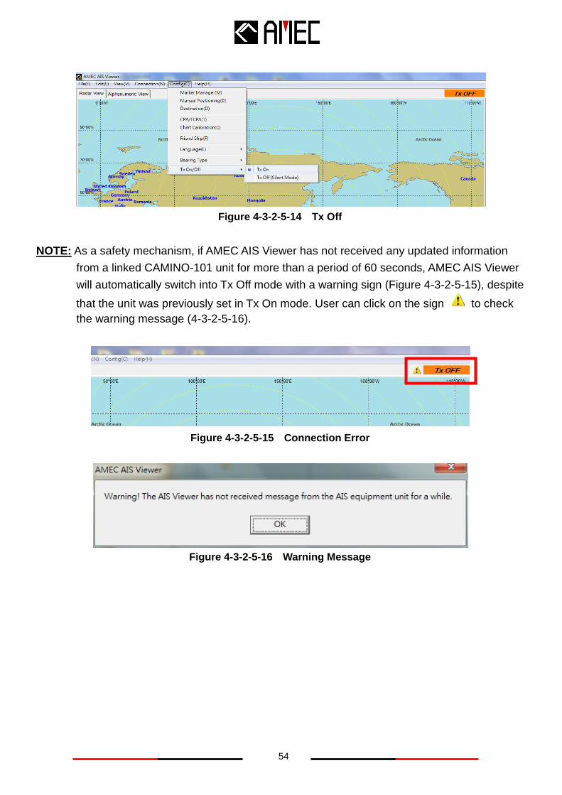
Figure 4-3-2-5-14 Tx Off
NOTE: As a safety mechanism, if AMEC AIS Viewer has not received any updated information
from a linked CAMINO-101 unit for more than a period of 60 seconds, AMEC AIS Viewer
will automatically switch into Tx Off mode with a warning sign (Figure 4-3-2-5-15), despite
that the unit was previously set in Tx On mode. User can click on the sign to check
the warning message (4-3-2-5-16).
Figure 4-3-2-5-15 Connection Error
Figure 4-3-2-5-16 Warning Message
55
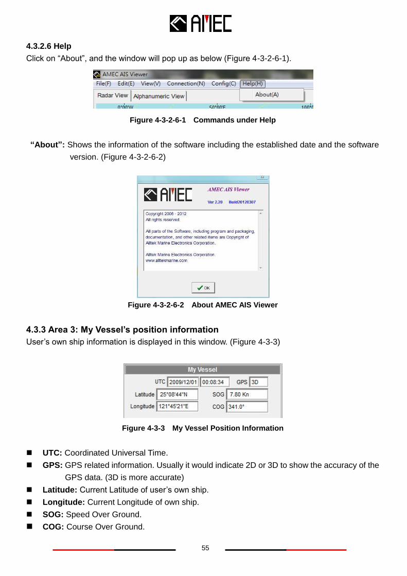
4.3.2.6 Help
Click on “About”, and the window will pop up as below (Figure 4-3-2-6-1).
Figure 4-3-2-6-1 Commands under Help
“About”: Shows the information of the software including the established date and the software
version. (Figure 4-3-2-6-2)
Figure 4-3-2-6-2 About AMEC AIS Viewer
4.3.3 Area 3: My Vessel’s position information
User’s own ship information is displayed in this window. (Figure 4-3-3)
Figure 4-3-3 My Vessel Position Information
UTC: Coordinated Universal Time.
GPS: GPS related information. Usually it would indicate 2D or 3D to show the accuracy of the
GPS data. (3D is more accurate)
Latitude: Current Latitude of user’s own ship.
Longitude: Current Longitude of own ship.
SOG: Speed Over Ground.
COG: Course Over Ground.
56
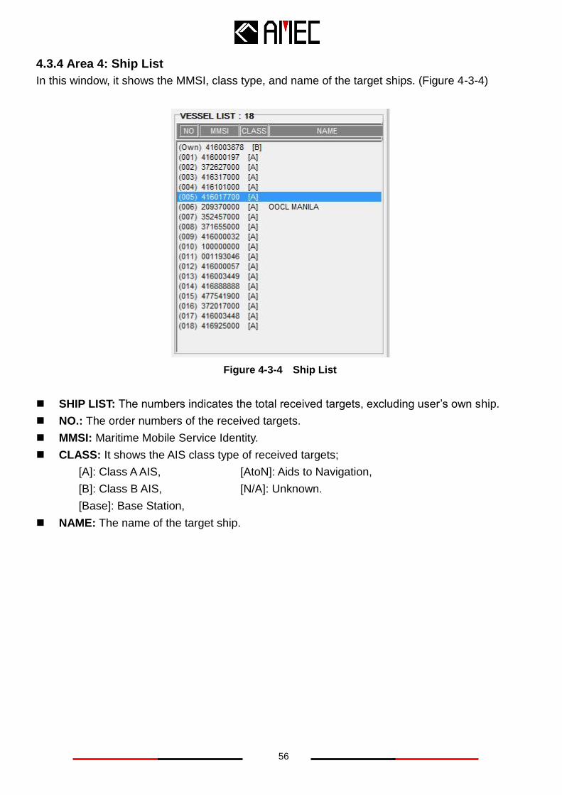
4.3.4 Area 4: Ship List
In this window, it shows the MMSI, class type, and name of the target ships. (Figure 4-3-4)
Figure 4-3-4 Ship List
SHIP LIST: The numbers indicates the total received targets, excluding user’s own ship.
NO.: The order numbers of the received targets.
MMSI: Maritime Mobile Service Identity.
CLASS: It shows the AIS class type of received targets;
[A]: Class A AIS, [AtoN]: Aids to Navigation,
[B]: Class B AIS, [N/A]: Unknown.
[Base]: Base Station,
NAME: The name of the target ship.
57
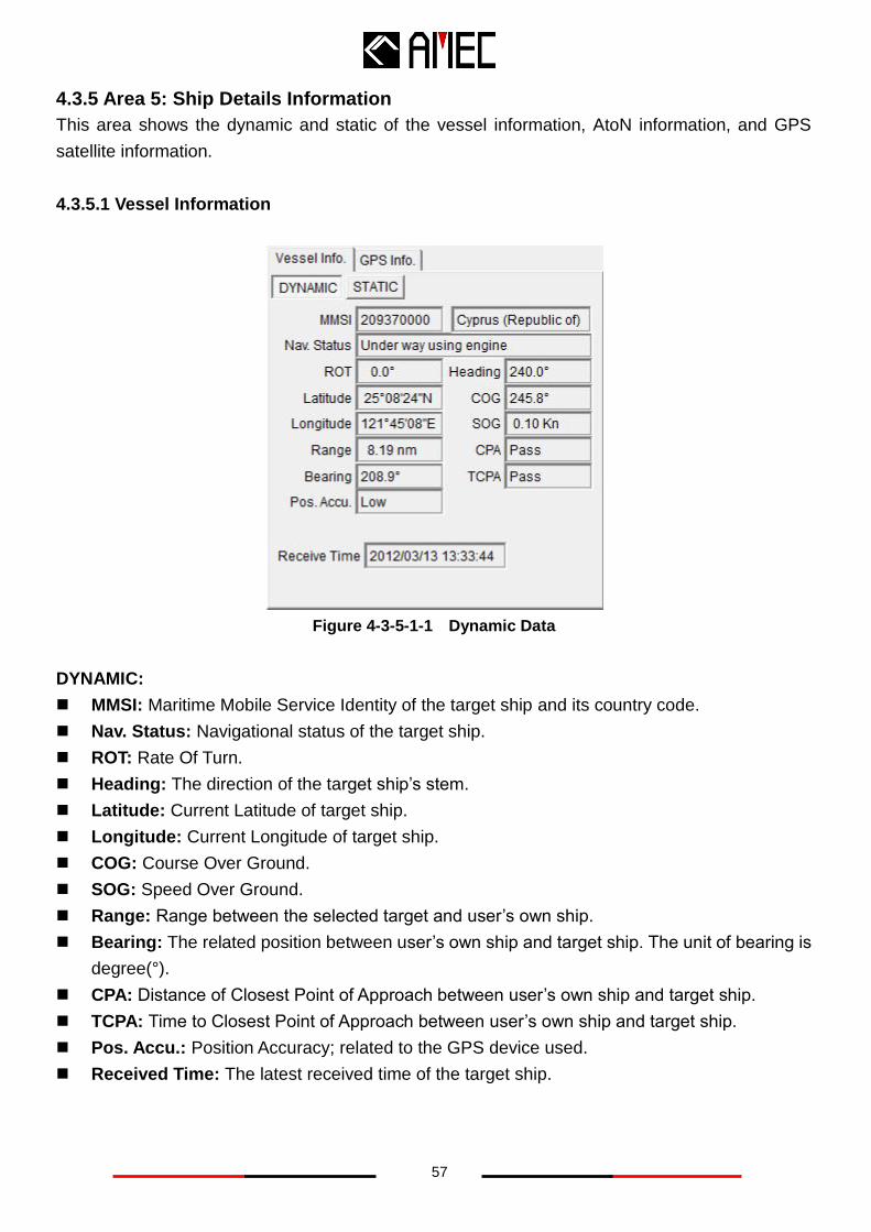
4.3.5 Area 5: Ship Details Information
This area shows the dynamic and static of the vessel information, AtoN information, and GPS
satellite information.
4.3.5.1 Vessel Information
Figure 4-3-5-1-1 Dynamic Data
DYNAMIC:
MMSI: Maritime Mobile Service Identity of the target ship and its country code.
Nav. Status: Navigational status of the target ship.
ROT: Rate Of Turn.
Heading: The direction of the target ship’s stem.
Latitude: Current Latitude of target ship.
Longitude: Current Longitude of target ship.
COG: Course Over Ground.
SOG: Speed Over Ground.
Range: Range between the selected target and user’s own ship.
Bearing: The related position between user’s own ship and target ship. The unit of bearing is
degree(°).
CPA: Distance of Closest Point of Approach between user’s own ship and target ship.
TCPA: Time to Closest Point of Approach between user’s own ship and target ship.
Pos. Accu.: Position Accuracy; related to the GPS device used.
Received Time: The latest received time of the target ship.
58
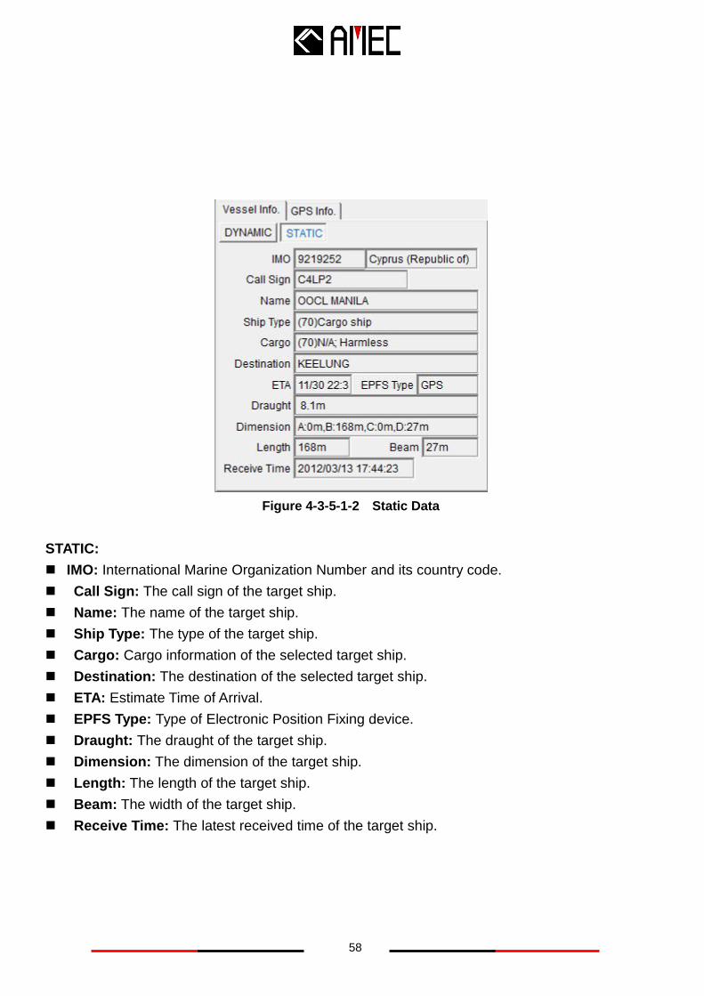
Figure 4-3-5-1-2 Static Data
STATIC:
IMO: International Marine Organization Number and its country code.
Call Sign: The call sign of the target ship.
Name: The name of the target ship.
Ship Type: The type of the target ship.
Cargo: Cargo information of the selected target ship.
Destination: The destination of the selected target ship.
ETA: Estimate Time of Arrival.
EPFS Type: Type of Electronic Position Fixing device.
Draught: The draught of the target ship.
Dimension: The dimension of the target ship.
Length: The length of the target ship.
Beam: The width of the target ship.
Receive Time: The latest received time of the target ship.
59
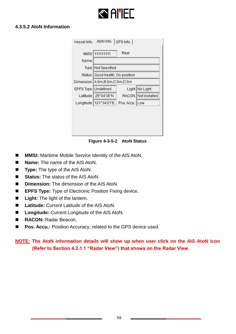
4.3.5.2 AtoN Information
Figure 4-3-5-2 AtoN Status
MMSI: Maritime Mobile Service Identity of the AIS AtoN.
Name: The name of the AIS AtoN.
Type: The type of the AIS AtoN.
Status: The status of the AIS AtoN.
Dimension: The dimension of the AIS AtoN.
EPFS Type: Type of Electronic Position Fixing device.
Light: The light of the lantern.
Latitude: Current Latitude of the AIS AtoN.
Longitude: Current Longitude of the AIS AtoN.
RACON: Radar Beacon.
Pos. Accu.: Position Accuracy; related to the GPS device used.
NOTE: The AtoN information details will show up when user click on the AIS AtoN icon
(Refer to Section 4.3.1.1 “Radar View”) that shows on the Radar View.
60
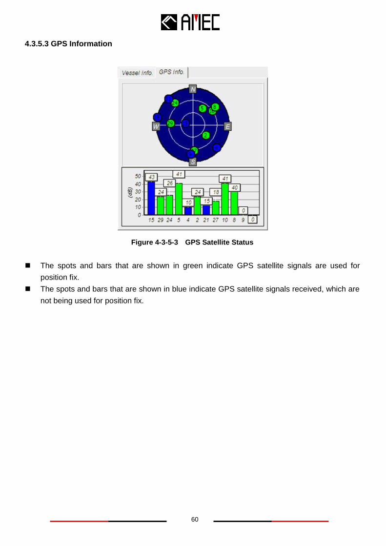
4.3.5.3 GPS Information
Figure 4-3-5-3 GPS Satellite Status
The spots and bars that are shown in green indicate GPS satellite signals are used for
position fix.
The spots and bars that are shown in blue indicate GPS satellite signals received, which are
not being used for position fix.
61
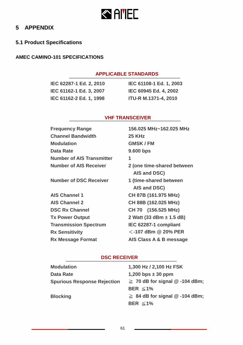
IEC 62287-1 Ed. 2, 2010
IEC 61162-1 Ed. 3, 2007
IEC 61162-2 Ed. 1, 1998
IEC 61108-1 Ed. 1, 2003
IEC 60945 Ed. 4, 2002
ITU-R M.1371-4, 2010
DSC RECEIVER
Modulation
Data Rate
Spurious Response Rejection
Blocking
1,300 Hz / 2,100 Hz FSK
1,200 bps ± 30 ppm
≧ 70 dB for signal @ -104 dBm;
BER ≦1%
≧ 84 dB for signal @ -104 dBm;
BER ≦1%
5 APPENDIX
5.1 Product Specifications
AMEC CAMINO-101 SPECIFICATIONS
Frequency Range
Channel Bandwidth
Modulation
Data Rate
Number of AIS Transmitter
Number of AIS Receiver
Number of DSC Receiver
AIS Channel 1
AIS Channel 2
DSC Rx Channel
Tx Power Output
Transmission Spectrum
Rx Sensitivity
Rx Message Format
156.025 MHz~162.025 MHz
25 KHz
GMSK / FM
9.600 bps
1
2 (one time-shared between
AIS and DSC)
1 (time-shared between
AIS and DSC)
CH 87B (161.975 MHz)
CH 88B (162.025 MHz)
CH 70 (156.525 MHz)
2 Watt (33 dBm ± 1.5 dB)
IEC 62287-1 compliant
<-107 dBm @ 20% PER
AIS Class A & B message
APPLICABLE STANDARDS
VHF TRANSCEIVER
62
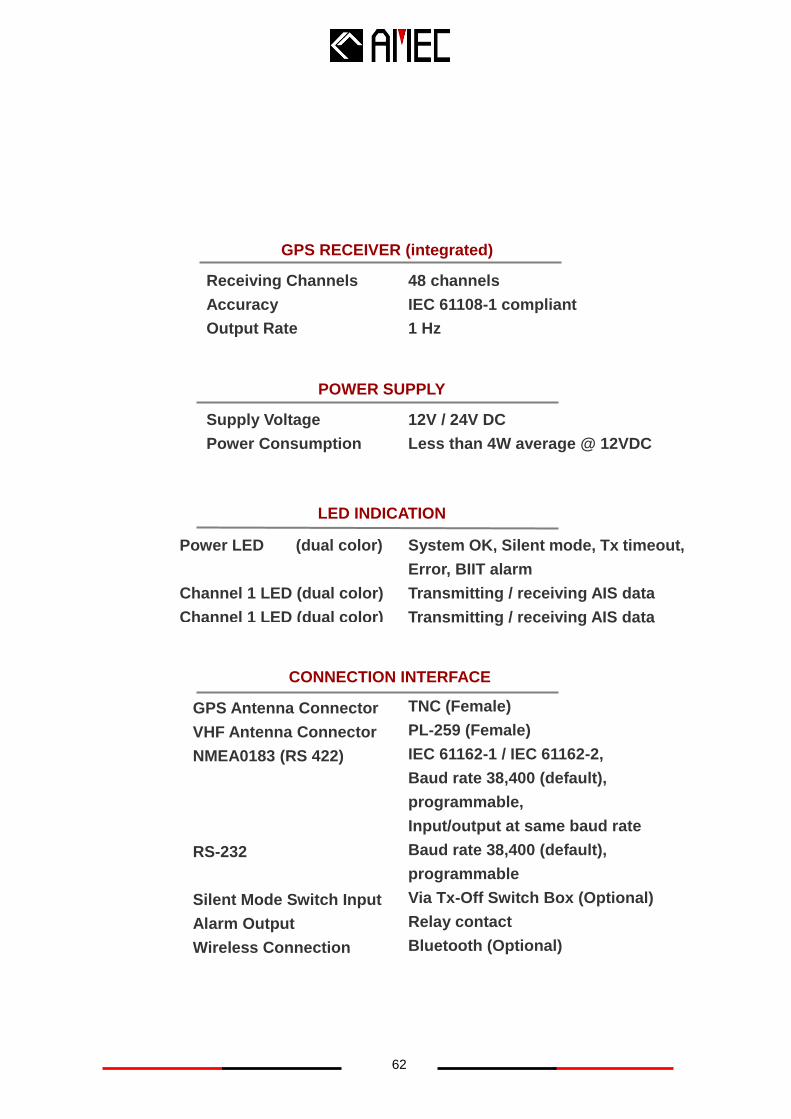
Power LED (dual color)
Channel 1 LED (dual color)
Channel 1 LED (dual color)
GPS RECEIVER (integrated)
Receiving Channels
Accuracy
Output Rate
48 channels
IEC 61108-1 compliant
1 Hz
POWER SUPPLY
Supply Voltage
Power Consumption
12V / 24V DC
Less than 4W average @ 12VDC
LED INDICATION
CONNECTION INTERFACE
GPS Antenna Connector
VHF Antenna Connector
NMEA0183 (RS 422)
RS-232
Silent Mode Switch Input
Alarm Output
Wireless Connection
TNC (Female)
PL-259 (Female)
IEC 61162-1 / IEC 61162-2,
Baud rate 38,400 (default),
programmable,
Input/output at same baud rate
Baud rate 38,400 (default),
programmable
Via Tx-Off Switch Box (Optional)
Relay contact
Bluetooth (Optional)
System OK, Silent mode, Tx timeout,
Error, BIIT alarm
Transmitting / receiving AIS data
Transmitting / receiving AIS data
63
PHYSICAL
Width
Height
Depth (include connectors)
Weight
140 mm (5.51 inch)
50 mm (1.91 inch)
200 mm (8.66 inch)
870 g
SOFTWARE TOOL
AMEC AIS Configuration
AMEC AIS Viewer
Configuration utility on PC,
standard supply in CD
AIS Viewer on PC,
standard supply in CD
ENVIRONMENTAL
Operating Conditions
Operating Temperature
Storage Temperature
Operating Humidity
Vibration, EMI, ESD
Waterproof
Compass Safe Distance-
Standard Magnetic
Compass Safe Distance-
Steering Magnetic
IEC 60945 “protected” category
-15°C~55°C
-25°C~70°C
95% RH at 40°C
IEC 60945 compliant
IPX5
0.45 m
0.30 m
64
GENERAL
ENVIRONMENTAL
PHYSICAL
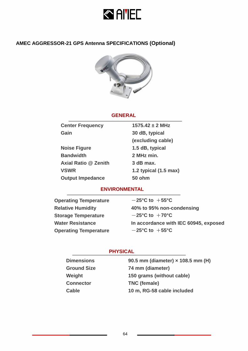
AMEC AGGRESSOR-21 GPS Antenna SPECIFICATIONS (Optional)
Center Frequency 1575.42 ± 2 MHz
Gain 30 dB, typical
(excluding cable)
Noise Figure 1.5 dB, typical
Bandwidth 2 MHz min.
Axial Ratio @ Zenith 3 dB max.
VSWR 1.2 typical (1.5 max)
Output Impedance 50 ohm
Operating Temperature -25°C to +55°C
Relative Humidity 40% to 95% non-condensing
Storage Temperature -25°C to +70°C
Water Resistance In accordance with IEC 60945, exposed
Operating Temperature -25°C to +55°C
Dimensions 90.5 mm (diameter) × 108.5 mm (H)
Ground Size 74 mm (diameter)
Weight 150 grams (without cable)
Connector TNC (female)
Cable 10 m, RG-58 cable included
65
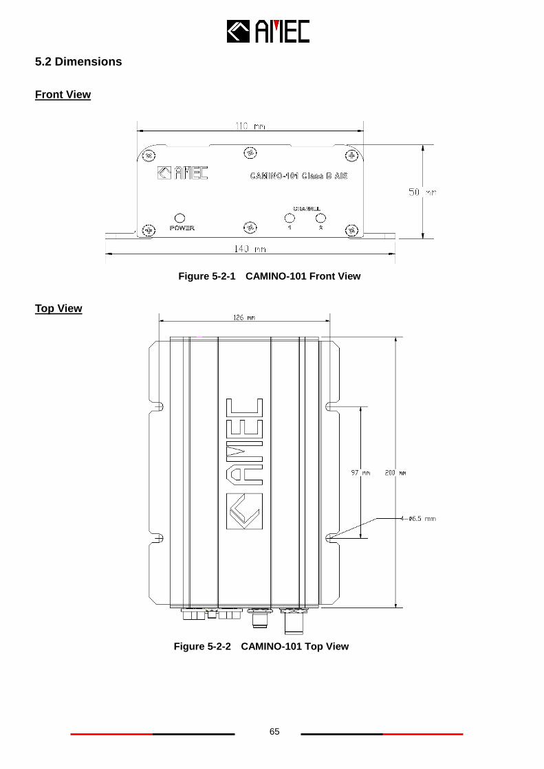
5.2 Dimensions
Front View
Top View
Figure 5-2-1 CAMINO-101 Front View
Figure 5-2-2 CAMINO-101 Top View
66
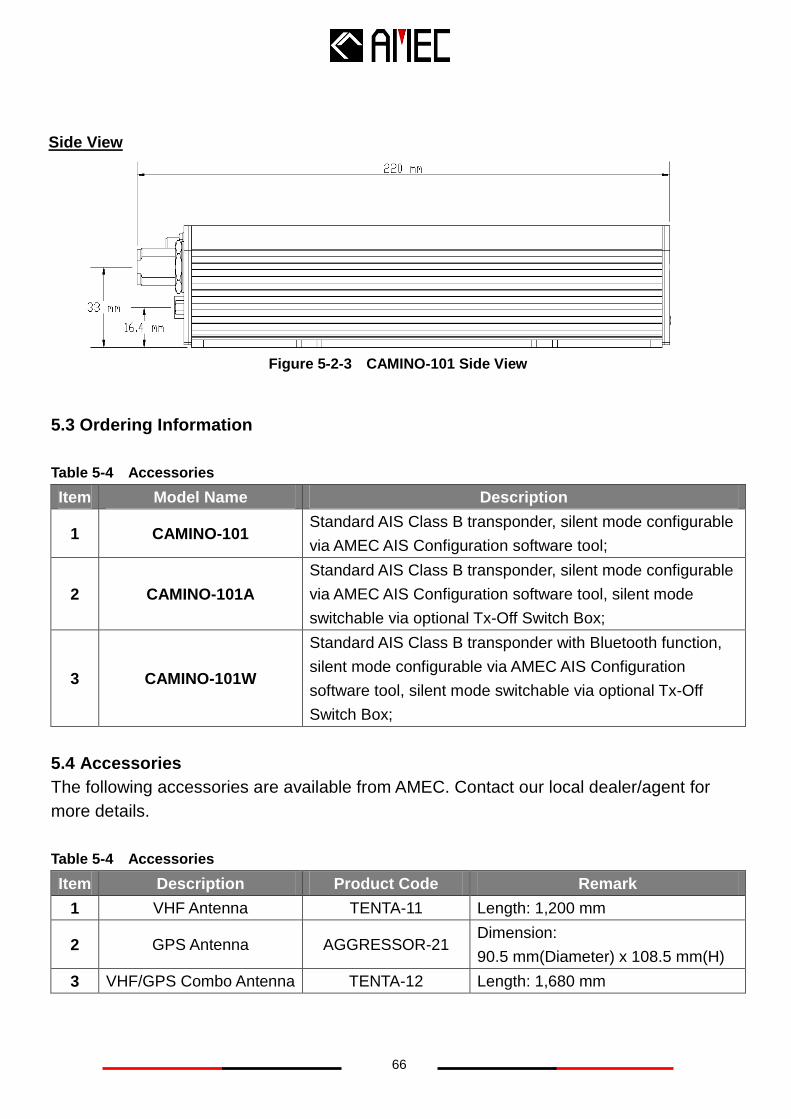
5.3 Ordering Information
Table 5-4 Accessories
Item Model Name Description
1 CAMINO-101 Standard AIS Class B transponder, silent mode configurable
via AMEC AIS Configuration software tool;
2 CAMINO-101A
Standard AIS Class B transponder, silent mode configurable
via AMEC AIS Configuration software tool, silent mode
switchable via optional Tx-Off Switch Box;
3 CAMINO-101W
Standard AIS Class B transponder with Bluetooth function,
silent mode configurable via AMEC AIS Configuration
software tool, silent mode switchable via optional Tx-Off
Switch Box;
5.4 Accessories
The following accessories are available from AMEC. Contact our local dealer/agent for
more details.
Table 5-4 Accessories
Item Description Product Code Remark
1 VHF Antenna TENTA-11 Length: 1,200 mm
2 GPS Antenna AGGRESSOR-21 Dimension:
90.5 mm(Diameter) x 108.5 mm(H)
3 VHF/GPS Combo Antenna TENTA-12 Length: 1,680 mm
Figure 5-2-3 CAMINO-101 Side View
Side View
67
5.5 Trouble Shooting
5.5.1 Diagnosis by LED Indicators
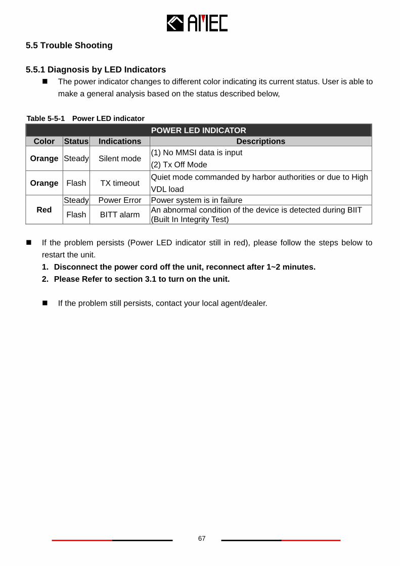
The power indicator changes to different color indicating its current status. User is able to
make a general analysis based on the status described below,
POWER LED INDICATOR
Color Status Indications Descriptions
Orange Steady Silent mode (1) No MMSI data is input
(2) Tx Off Mode
Orange Flash TX timeout Quiet mode commanded by harbor authorities or due to High
VDL load
Red
Steady Power Error Power system is in failure
Flash BITT alarm An abnormal condition of the device is detected during BIIT (Built In Integrity Test)
If the problem persists (Power LED indicator still in red), please follow the steps below to
restart the unit.
1. Disconnect the power cord off the unit, reconnect after 1~2 minutes.
2. Please Refer to section 3.1 to turn on the unit.
If the problem still persists, contact your local agent/dealer.
Table 5-5-1 Power LED indicator
68
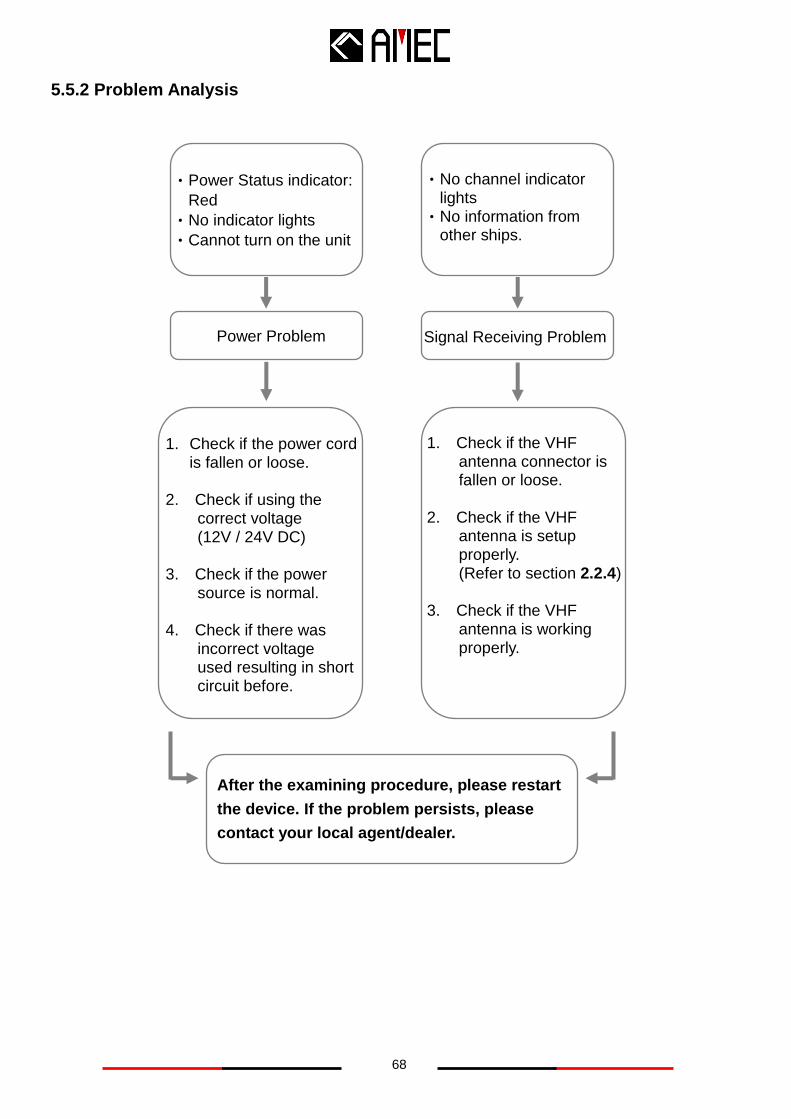
5.5.2 Problem Analysis
Power Problem
1. Check if the power cord is fallen or loose.
2. Check if using the correct voltage
(12V / 24V DC) 3. Check if the power source is normal. 4. Check if there was incorrect voltage
used resulting in short circuit before.
‧Power Status indicator:
Red
‧No indicator lights
‧Cannot turn on the unit
Signal Receiving Problem
‧No channel indicator lights
‧No information from other ships.
1. Check if the VHF antenna connector is fallen or loose.
2. Check if the VHF
antenna is setup properly. (Refer to section 2.2.4) 3. Check if the VHF
antenna is working properly.
After the examining procedure, please restart
the device. If the problem persists, please
contact your local agent/dealer.
69
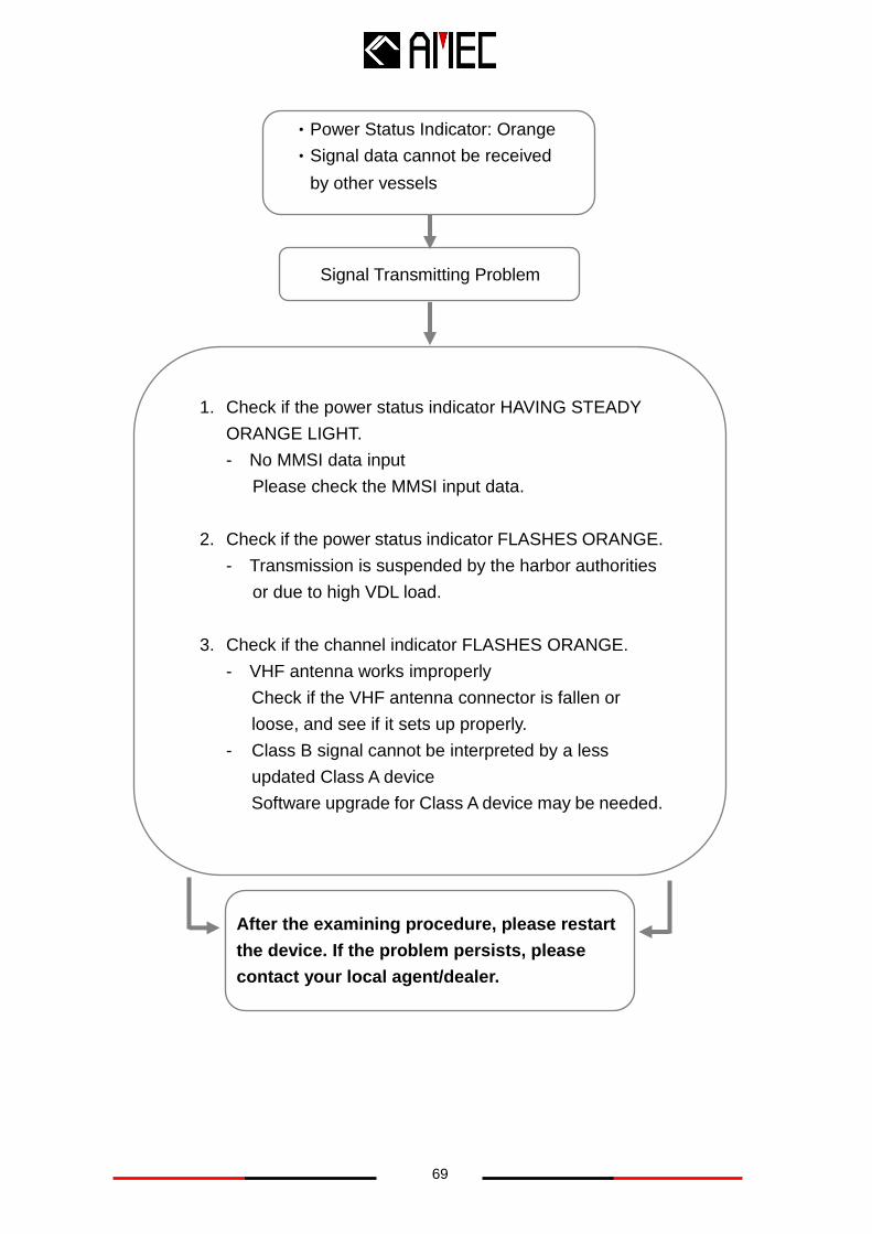
‧Power Status Indicator: Orange
‧Signal data cannot be received
by other vessels
Signal Transmitting Problem
1. Check if the power status indicator HAVING STEADY
ORANGE LIGHT.
- No MMSI data input
Please check the MMSI input data.
2. Check if the power status indicator FLASHES ORANGE.
- Transmission is suspended by the harbor authorities
or due to high VDL load.
3. Check if the channel indicator FLASHES ORANGE.
- VHF antenna works improperly
Check if the VHF antenna connector is fallen or
loose, and see if it sets up properly.
- Class B signal cannot be interpreted by a less
updated Class A device
Software upgrade for Class A device may be needed.
After the examining procedure, please restart
the device. If the problem persists, please
contact your local agent/dealer.
70
6 AMEC WORLD WIDE WARRANTY
Limited warranty
Subject to the terms, conditions and limitations set forth in this Worldwide Limited Warranty
(hereinafter the “Warranty”), AMEC warrants that its products, when properly installed and used,
will be free from defects in material and workmanship for a period of twelve (12) months, from the
date of first purchase (the ‘Warranty Period’)
For the purposes of this warranty, ‘date of first purchase’ means the date that the product was
purchased by the first retail customer, or by the institutional customer, or in the case of a product
installed on a new vessel or any other marine related platform by a certified AMEC original
equipment manufacturer (a ‘AMEC OEM’), the date that such vessel was purchased by the first
retail customer.
AMEC will, at its sole option, repair or replace any defective products or components returned
during the Warranty Period in accordance with the terms, conditions and limitations set forth below.
Such repairs or replacement will be the sole remedy of the customer under this Warranty.
Standard Warranty Service
To qualify for standard warranty service the product must be returned to a AMEC-certified service
agent (i) within the Warranty Period, and (ii) within thirty (30) days of the alleged product failure.
Any products returned must be securely packaged and sent pre-paid and insured to AMEC or to a
AMEC-certified service agent. All products returned must be accompanied by a copy of the
original sales receipt to be eligible for standard warranty service.
Obtaining Warranty Service
A list of AMEC-certified service agents is available from AMEC Technical Support at
www.alltekmarine.com
Other conditions
This Warranty is fully transferable provided that you furnish the original proof of purchase to the
AMEC -certified service agent. This Warranty is void if the label bearing the serial number has
been removed or defaced.
Limitation and Exclusions
In addition to any other limitations and exclusions set forth herein, AMEC is not responsible for,
and this Warranty does not cover:
Failure due to abuse, misuse, accident, unauthorized alteration, modification or repair, improper
installation or operation (whether or not by a AMEC-certified service agent) or improper storage,
shipping damage or corrosion;

71
Costs associated with routine system checkouts, alignment/calibration, sea trials or
commissioning;
Defects or damage that result from the use of non-AMEC branded or certified products,
accessories or other peripheral equipment, including without limitation housings, parts, or
software;
Aftermarket software (i.e. all software other than the original operating software sold with the
products);
Products that have been refurbished, reconditioned, or remanufactured (The foregoing does not
apply to products repaired or replaced pursuant to the terms of this Warranty).
Products that have been dismantled resulting in the broken label on the Products;
costs associated with overtime or premium labor costs;
differences in material, coloring or size that may exist between actual products and the pictures or
descriptions of such products in our advertising, advertising literature or on the Internet;
TO THE EXTENT PERMITTED BY APPLICABLE LAW, THE FOREGOING WARRANTY IS
AMEC’S SOLE WARRANTY AND IS APPLICABLE ONLY TO NEW PRODUCTS PURCHASED
WORLDWIDE. THE PROVISIONS OF THIS WARRANTY ARE IN LIEU OF ANY OTHER
WRITTEN WARRANTY, WHETHER EXPRESSED OR IMPLIED, WRITTEN OR ORAL,
INCLUDING ANY WARRANTY OF MERCHANTABILITY OR FITNESS FOR A PARTICULAR
PURPOSE.
THE LIABILITY OF AMEC TO A CUSTOMER UNDER THIS WARRANTY, WHETHER FOR
BREACH OF CONTRACT, TORT, BREACH OF STATUTORY DUTY OR OTHERWISE SHALL IN
NO EVENT EXCEED AN AMOUNT EQUAL TO THE TOTAL PURCHAE PRICE OF THE
PRODUCT GIVING RISE TO SUCH LIABILITY AND IN NO EVENT SHALL AMEC BE LIABLE
FOR SPECIAL, INCIDENTAL, CONSEQUENTIAL OR INDIRECT DAMAGES OR LOST OF
GOODWILL, REPUTATION, LOSS OF OPPORTUNITY OR INFORMATION, DATA, SOFTWARE
OR APPLICATIONS.
SOME JURISDICTIONS DO NOT ALLOW EXCLUSION OR LIMITATION OF INCIDENTAL OR
CONSEQUENTIAL DAMAGES SO THE ABOVE LIMITATIONS OR EXCLUSIONS MAY NOT
APPLY TO YOU. THIS WARRANTY GIVES YOU SPECIFICLEGAL RIGHTS AND YOU MAY
ALSO HAVE OTHER RIGHTS, WHICH VARY FROM JURISDICTION TO JURISDICTION.
This Warranty supersedes and replaces all previous Warranties.
In the event that any term or provision contained in this Warranty is found to be invalid, illegal or
unenforceable by a court of competent jurisdiction, then such provision shall be deemed modified
to the extent necessary to make such provision enforceable by such court, taking into account the
intent of the parties.
72
No oral or written representations made by AMEC or any seller, reseller or distributor of the
products, including employees and agents thereof, shall create any additional warranty
obligations, increase the scope, or otherwise modify in any manner the terms of this Warranty.
All AMEC products sold or provided hereunder are merely aids to navigation. It is the
responsibility of the user to exercise discretion and proper navigational skill independent of any
AMEC product.
7 FEDERAL COMMUNICATION COMMISSION INTERFERENCE STATEMENT
This equipment has been tested and found to comply with the limits for a Class A digital device,
pursuant to Part 15 of FCC Rules. These limits are designed to provide reasonable protection
against harmful interference in a residential installation. This equipment generates uses and can
radiate radio frequency energy and, if not installed and used in accordance with the instructions,
may cause harmful interference to radio communications. However, there is no guarantee that
interference will not occur in a particular installation. If this equipment does cause harmful
interference to radio or television reception, which can be determined by turning the equipment off
and on, the user is encouraged to try to correct the interference by one of the following
measures:
Reorient or relocate the receiving antenna.
Increase the separation between the equipment and receiver.
Connect the equipment into an outlet on a circuit different from that to which the receiver is
connected.
Consult the dealer or an experienced radio/TV technician for help.
This device complies with Part 15 of the FCC Rules. Operation is subject to the following two
conditions: (1) This device may not cause harmful interference, and (2) this device must accept
any interference received, including interference that may cause undesired operation.
73
8 DECLARATION OF CONFORMITY
Hereby, Alltek Marine Electronics Corp. (AMEC) declares that this CAMINO-101 is in
compliance with the essential requirements and other relevant provisions of Directive
1999/5/EC.
9 INDUSTRY CANADA NOTICE TO USERS
AMEC cannot accept responsibility for any failure to satisfy the protection requirements resulting
from a non-recommended modification of the product.
Operation is subject to the following two conditions:
(1) this device may not cause harmful interference, and
(2) this device must accept any interference received, including interference that may cause
undesired operation of the device.
10 ABBREVIATIONS
AIS Automatic Identification System
COG Course Over Ground
CPA Distance to Closest Point of Approach
CSTDMA Carrier-Sense Time Division Multiple Access
DSC Digital Selective Calling
ECS Electronic Chart System
ETA Estimated Time of Arrival
GPS Global Positioning System
IMO International Maritime Organization
MMSI Maritime Mobile Service Identity
SOG Speed Over Ground
SRM Safety Related Message
TCPA Time to Closest Point of Approach
TDMA Time Division Multiple Access
UTC Coordinated Universal Time
VHF Very High Frequency
VTS Vessel Traffic Services