Embed Size (px)
Citation preview

© KEYENCE CORPORATION, 1999 NKVS-UM-4-1100 Printed in Japan
96M0365
How this manual is organized:
The Visual KV Series User’s Manual is composed of 3 separatemanuals; 1-Installation, 2-Support Software, 3-Programming.Please read each manual relevant to your purpose.
SupportSoftware
1. Introduction
2. Editor
3. Simulator
4. Monitor
5. Appendices
Programming
1. Programming
2. Instructions
3. Interrupts
4. High-speed Counters
5. Positioning Control
6. Interrupts, High-speedCounters, PositioningControl
7. Serial Communication
8. ProgrammingExamples
INDEX
Installation
1. Configuration andSpecifications
2. System Installation
3. Access Window
4. KV-D20 OperatorInterface Panel
5. KV-10/80 Hardware
6. Handheld Program-mer
7. KV-L2 Serial InterfaceModule
8. KV-AN6 Analog I/OModule
9. KV-AD4/DA4 AnalogI/O Unit
10. Troubleshooting
11. Appendices
Visual KV Series 2 S
upport S
oftw
are
User's ManualVisual KV Series
2Support software
1 2 3
Specifications are subject to change without notice.
KEYENCE CORPORATION1-3-14, Higashi-Nakajima,Higashi-Yodogawa-ku,Osaka, 533-8555, JapanPHONE: 81-6-6379-2211FAX: 81-6-6379-2131
AFFILIATED COMPANIES
KEYENCE CORPORATION OF AMERICAPHONE: 201-930-0100 FAX: 201-930-0099
KEYENCE DEUTSCHLAND GmbHPHONE: 06102-36 89-0 FAX: 06102-36 89-100
KEYENCE (UK) LIMITEDPHONE: 01908-696900 FAX: 01908-696777
KEYENCE FRANCE S.A.PHONE: 01 47 92 76 76 FAX: 01 47 92 76 77
KEYENCE SINGAPORE PTE LTDPHONE: 392-1011 FAX: 392-5055
KEYENCE (MALAYSIA) SDN BHDPHONE: 03-252-2211 FAX: 03-252-2131
KEYENCE (THAILAND) CO., LTDPHONE: 02-369-2777 FAX: 02-369-2775
KEYENCE THAIWAN CO., LTDPHONE: 02-2627-3100 FAX: 02-2798-8925
KEYENCE KOREA CORPORATIONPHONE: 02-563-1270 FAX: 02-563-1271

Safety PrecautionsThis instruction manual describes the operation and function of the KV Series PLC.Read this manual carefully to ensure safe use and maximum performance from yourKV Series PLC.
SymbolsThe following symbols alert you to important messages. Be sure to read thesemessages carefully.
Failure to follow instructions may lead to injury. (electricshock, burn, etc.)
Failure to follow instructions may lead to product damage.
Provides additional information on proper operation.
ConventionsThis manual describes the operation/function of all Keyence KV Series PLC.Note following conventions when you use.
General Precautions• At startup and during operation, be sure to monitor the functions and perfor-
mance of the KV Sereis PLC.
• We recommend that you take substantial safety measures to avoid any damagein the event a problem occurs.
• Do not open or modify the KV Series PLC or use it in any way other than de-scribed in the specifications.
• When the KV Series PLC is used in combination with other instruments, func-tions and performance may be degraded, depending on operating conditions andthe surrounding environment.
• Do not use the KV Series PLC for the purpose of protecting the human body.
Note: The built-in display may show the error message "Error 40" blinking the veryfirst time you turn on the power supply to the Visual KV Series. Press any keyaround the display to cancel this message.The Visual KV Series shows this message when no program is loaded.
WARNING
CAUTION
Note:
(1)
Visual KV (Series) KV-10AR/AT/DR/DT KV-16AR/AT/DR/DTKV-10xx, 16xx, 24xx, 40xx KV-24AR/AT/DR/DT KV-40AR/AT/DR/DT
Conventional KV (Series) KV-10R(W)/T(W) KV-16R(W)/T(W)KV-300 (Series) KV-24R(W)/T(W) KV-40R(W)/T(W)KV-10/80 (Series) KV-80R(W)/T(W)
KV-300

Note to UserWhen using the Visual KV Series in the following conditions or environments, besure to use the Visual KV Series with sufficient margin regarding the rating andfunctions, take appropriate safety precautions such as fail-safe, and contact oursales personnel if any questions arise.
• Use in conditions or environments not described in this manual
• Use for nuclear power control, railway facilities, air service facilities, vehicles,combustion devices, medical equipment, amusement machines, safety equip-ment, etc.
• Use for applications where large effects are predicted to be given on human livesand properties and safety is especially requested.
Restriction on Acquiring the CE Marking Restriction to be compatible with EMC directives
• When using a relay output type unit (whose model name ends with "R"), connectspark killers having the appropriate withstand voltage against the load to theoutput terminals in parallel to contacts (because the unit discharges when a relaycontact becomes open and noise is generated). In our experiments, we use thefollowing models of spark killers.
XEB0101 0.1 µF-10 Ω manufactured by OKAYA DENKI SANGYO
The following 1-turn ferrite core is added to the AC power input circuit of the KV-40AR/T, the KV-24AR/T and to the DC power input circuit of the KV-40DR/T.
ZCAT3035-1330 manufactured by TDK
Note: The contents above do not by themselves ensure that the entire machinemanufactured in accordance with the above contents is compatible with EMCdirectives.
You must judge by yourself whether or not the entire machine is compatible withEMC directives because compatibility may change depending on the componentconfiguration, wiring and location inside of the machine.
Restriction on compatibility with low-voltage directives (IEC-1010-1)
• Use insulated type crimp-style terminals.
• For wiring materials, use lead wires whose sheath is 0.4 mm or more.
• The Visual KV Series is allowed to be installed in a vertical position only.(Spacers for expansion units are not available.)
• Be sure to use the Visual KV Series inside the control panel.
(2)

Features of the Visual KV Series Extremely small
The Visual KV Series is the smallest in the world among AC type PLCs equippedwith screw terminal blocks, and saves installation space.
Extremely fast
The minimum scan time is 140 µs and minimum instruction execution time is 0.7µs, which is the fastest control in its class.
AC power built-in type newly addedAC power built-in type units are newly added. This type can be used in smallspaces where a switching power supply unit cannot be installed.
Excellent Access Window
An Access Window with two-color backlight is adopted in all models to facilitatechanging and monitoring of device data. Changing between RUN mode andPROGRAM mode, checking the error code when an error has occurred, etc. canbe performed in a Visual KV Series unit without the need for any handheldprogrammer.The analog trimmer, which has been popular in the conventional KV Series, isdigitized to enable more detail settings. [Digital trimmers]
User message setting function
In the Access Window, 256 different user messages can be displayed. Thisfunction can be used to give instructions on works on the production line, indicateabnormalities in the units, etc.
Program write in RUN mode
Ladder programs can be changed even while the system is running.
Equipped with two serial portsVisual KV Series basic units are equipped with two serial ports to connect periph-eral units, improving the debug environment.(The KV-10xx is equipped with only one serial port.)
Easy Ramp-up/down control function
The one-axis motor control function is offered separately from high-speedcounters so that feedback control is enabled.
Equipped with two 24-bit high-speed 30 kHz, two-phase counters
The Visual KV Series is equipped with two high-speed counters each with a two-point comparator output function that enables high-speed encoder input.
Specified frequency pulse output function
High-speed counters can function as pulse oscillators of 50 kHz maximum witheasy setting, without creating a complicated ladder program.
Frequency counter functionHigh-speed counters can function as frequency counters with easy setting,without creating complicated ladder programs.
Cam switch function
High-speed counters can function as cam switches with easy setting, withoutcreating complicated ladder programs.
(3)

Interrupt function
The Visual KV Series is equipped with four high-speed interrupt inputs of10 µs maximum.
Input time constant change function
The time constant can be set in 7 steps from 10 µs to 10 ms.
Double memory backup functionsIn addition to a conventional SRAM battery backup function, the Visual KV Seriesis also equipped with an EEPROM backup function.
Compatibility with Conventional KV Series Peripheral UnitsThe Visual KV Series functions as a high-end compatible model of the conventionalKV Series. Peripheral units of the conventional KV Series such as the ladder supportsoftware "KV IncrediWare (DOS)" and "LADDER BUILDER for KV" and thehandheld programmer KV-P3E(01) can be used since they are part of the Visual KVSeries.However, it should be noted that the contents have changed as follows.
• The internal clock cycle of high-speed counters consists of three types: 1 µs, 10µs, and 100 µs.
• The time constant for an input relay specified by the HSP instruction is 10 µs.
• The analog trimmer function is set with the Access Window built into the basicunit.
• The available device setting range of the TMIN instruction is from 0 to 65535.[Handheld programmer KV-P3E(01) can display 0 to 9999 .]
• The RUN/PROGRAM LED is displayed in the Access Window provided on thefront face of the basic unit.
• Transistor output is not independent, but is common.
• With the transistor type, the output terminal layout is different.
• The specifications for output current of transistor outputs Nos. 500 to 502 is 100mA.
• Conventional KV Series expansion units are not available as expansion units forthe Visual KV Series.
• The channel setting switch is not provided for expansion units. Channels aredetermined in connection order.
• Scans in expansion I/O units are not synchronous with the scan time in Visual KVSeries basic units.
• Assignment of special utility relays has partially changed.
• Data memory device Nos. DM1000 to DM1999 are assigned as special datamemories.
(4)

Cautions when using the previous version of ladder support softwarePay strict attention to the following items when using the ladder support software.
• When using the ladder support software "KV IncrediWare (DOS)" or "LADDERBUILDER for KV Ver. 1.0x", set the model to "KV-300".
• DM0 to DM1999 are only available.
When the ladder support software "LADDER BUILDER for KV Ver. 1.0x" isused, do not use the monitor’s Change All function. If the Change All functionis used, the basic unit may be damaged. Never use the Change All function.
Peripheral units and other units incompatible with the Visual KV SeriesPeripheral units in the conventional KV Series and other units shown below are notcompatible with the Visual KV Series.
• Expansion I/O units for the conventional KV Series: KV-8ER/8ET/8EX/16EX/8EYR/8EYT/16EYR/16EYT
• Analog I/O units for the conventional KV Series: KV-AD4/DA4
Cautions when Using the Serial PortThe KV-16xx/24xx/40xx units are equipped with two RJ-11 modular connectors forserial communication.When using them, pay strict attention to the following contents:
• Programs can be transferred and monitored using either communication port A orB. However, never connect the ladder software and a handheld programmer tothe two ports at the same time.
• The KV-D20 operator interface panel can be connected to either communicationport A or B. However, only one KV-D20 unit can be connected to a single basicunit.
• Never leave both the KV-D20 operator interface panel and KV-P3E(01) handheldprogrammer on simultaneously for a long period of time.
CAUTION
(5)

(6)
Cautions when writing in RUN mode• In the Visual KV Series, a program can be changed using the ladder sup-
port software "LADDER BUILDER for KV" even while the program is run-ning.
• Pay strict attention to safety when performing any writes in RUN mode.
• The situation may become extremely dangerous depending on the status ofthe controller device connected to the PLC or the program used.
When writing in RUN mode, each function is offered as follows:
Note 1: When a ladder program is changed while it is running, it is not saved in theEEPROM but is saved in the SRAM, then will be saved in the EEPROM when thepower is next turned on. If the power OFF period is 2 months or longer at 25°C (20days or longer at 25°C for the KV-10xx) after a ladder program is changed in RUNmode, the changed ladder program may become corrupted. To prevent inconsisten-cies, turn on the power once so that the changed program is saved in the EEPROM.
Note 2: If an error occurs in the Visual KV Series basic unit while a program is beingwritten in RUN mode, the Visual KV Series basic unit changes to PROGRAM modeand the existing program which is being written may be deleted. In such a case,transfer the program again.
WARNING
noitcnufVK gninnurelihW gnitirwretfA
•retnuocdeeps-hgiHretnuocdeeps-hgiH
rotarapmoc
.senodesuehteteleD dezilaitinI
.senowenllA dezilaitinI
seulavtesehtegnahCretnuocdeeps-hgihrof
desusrotarapmoc
retnuocdeeps-hgihrofseulavtesnehWtnerruceht,degnahcerasrotarapmocerasretnuocdeeps-hgihehtfoseulav
sayawemasehtnidegnahcosla)10(E3P-VKehthtiwdetucexesi07NUF
.remmargorpdlehdnah " :retnuoc/remitfoeulavtesgnignahC
)222-1.p("07NUF
egnahcoN .sutatstnerrucnisniameR
yrailixualanretnIlaiceps/yaleryaleryrailixua
dleH
-dna-pupmarysaElortnocnwod
noitcnuf.detelpmocsahtuptuotnerruclitnunoitareposeunitnoC
noitcnufhctiwsmaC .noitareposeunitnoC
ycneuqerfdeificepSnoitcnuftuptuoeslup
.noitareposeunitnoC
retnuocycneuqerFnoitcnuf
.noitareposeunitnoC
rofeulavsuoiverPlaitnereffidnoitcurtsni
retfasnoitcurtsnilaitnereffidrofderiuqcasieulavsuoiverpehTybdetcetedebtonnactnatsnisihttadegnahcsyaleR.noisrevnoc
.noitaitnereffid

(7)
How this manual is organizedThe Visual KV Series User’s Manual is composed of 3 separate manuals;1-Installation, 2-Support Software, 3-Programming. Please read each manualrelevant to your purpose.
1 InstallationChapter 1 Configuration and Specifications [Visual KV Series Only]
Describes the system configuration of the Visual KV Series, the names and functions ofeach part, and the specifications.
Chapter 2 System Installation [Visual KV Series Only]Describes the installation and connection of each Visual KV Series unit as well assystem maintenance.
Chapter 3 Access Window [Visual KV Series Only]Describes the Access Window used for changing and monitoring data.
Chapter 4 KV-D20 Operator Interface Panel [Visual KV Series Only]Describes the KV-D20 Operator Interface Panel used for changing, monitoring, anddisplaying the status of inside relays, timers, counters and data memories.
Chapter 5 KV-300, KV-10/80 Hardware [KV-300, KV-10/80 Series Only]Describes the hardware specifications and wirings for KV-300 and KV-10/80 Series.
Chapter 6 Handheld ProgrammerDescribes how to use the handheld programmer and memory card.
Chapter 7 KV-L2 Serial Interface Module [KV-300 Series Only]Describes the serial interface modules for KV-300 Series.
Chapter 8 KV-AN6 Analog I/O Module [KV-300 Series Only]Describes the optional Analog I/O module for KV-300 Series
Chapter 9 KV-AD4/DA4 Analog I/O Unit [KV-10/80 Series Only]Describes the optional Analog I/O unit for KV-10/80 Series.
Chapter 10 TroubleshootingThis chapter describes the error code list, countermeasures against problems, and errorindications for each unit.
AppendicesThe appendix includes a list of ladder program applications and the index.
2 Support SoftwareChapter 1 Introduction
Describes the items included in the package, the product outline, the method to connecta personal computer, the installation method, etc.

(8)
Chapter 2 EditorDescribes the operating procedures in Editor mode.
Chapter 3 SimulatorDescribes the operating procedures in Simulator mode.
Chapter 4 MonitorDescribes the operating procedures in Monitor mode.
AppendicesIncludes instructions list, devices list, sample program list and quick reference for keyoperation and shortcuts.
3 ProgrammingChapter 1 Programming
Describes basic knowledge including program creation procedures, device configuration,relay assignments, special functions to set and confirm Visual KV Series operations, aswell as the extended ladder diagrams. Understand the contents described here com-pletely at first before creating programs.
Chapter 2 InstructionsDescribes the concrete usage of instructions in the KV Series.Refer to "Chapter 3 Interrupts" on page 3-183 for details of interrupt instructions.Refer to "Chapter 4 High-speed counters" on page 3-195 for details of the high-speedcounters used in the application instruction.
Chapter 3 Interrupts [Visual KV Series Only]The interrupt processing function executes an interrupt program when an external inputor request from the high-speed counter comparator (interrupt factor) is encounteredduring KV operation.This chapter describes the types of interrupt factors as well as inputs and outputsencountered during interrupt processing.
Chapter 4 High-speed Counters [Visual KV Series Only]Describes high-speed counters and high-speed counter comparators, which allow high-speed pulse measurement and pulse output, independent of the scan time.
Chapter 5 Positioning Control [Visual KV Series Only]Describes ramp-up/down control of stepping motors and servo motors.
Chapter 6 Interrupts, High-speed Counters, Positioning Control [KV-300, KV-10/80 Series Only]Describes ramp-up/down control of stepping motors and servo motors.
Chapter 7 Serial CommunicationThe KV Series can be connected to an external device with an RS-232C interface toestablish communication.This chapter describes communications specifications, how to connect the KV Series toexternal devices, and how to perform communication.
Chapter 8 Programming ExamplesDescribes the typical programming examples for KV-10/80 Series. These programs canbe used for Visual KV Series. However, pay attention to the I/O addressing compatibilitybefore use.

(9)
Contents 2 Support software
Chapter 1 Introduction
1.1 Items Included in the Package ........................................................................2-2
1.2 Outline of the Ladder Builder for KV ..............................................................2-31.2.1 Operating environment and system configuration ..............................................2-31.2.2 Features and functions of the Ladder Builder for KV ..........................................2-4
Features of the Ladder Builder for KV .........................................................2-4Functions of the Ladder Builder for KV ........................................................2-6
1.3 Before Programming .......................................................................................2-7Machines to be prepared .............................................................................2-7
1.3.1 Differences from the KV IncrediWare (DOS) ......................................................2-81.3.2 Differences from the Ladder Builder for KV Ver 1.0 ........................................... 2-8
1.4 Installing the Software .....................................................................................2-91.4.1 Preparation for installation ..................................................................................2-91.4.2 Installation Procedure .......................................................................................2-10
Installation in Windows 95 .........................................................................2-10Installation in Windows 3.1 ........................................................................2-12
1.5 Cautions for Use ............................................................................................2-13
1.6 Basic Operations ...........................................................................................2-141.6.1 Program creation flow and available modes .....................................................2-141.6.2 Starting up and exiting from the software .........................................................2-161.6.3 Screen ..............................................................................................................2-181.6.4 Mouse operation and keyboard operation ........................................................2-211.6.5 Online Help .......................................................................................................2-23
Chapter 2 Editor
2.1 Outline of the Editor Functions ....................................................................2-262.1.1 Cautions for editing ladder programs ................................................................2-26
2.2 Edit Screen .....................................................................................................2-272.2.1 Name and function of each part of the screen ..................................................2-272.2.2 Ladder program window screen .......................................................................2-28
2.3 File Management ............................................................................................2-292.3.1 Creating a new file ............................................................................................2-292.3.2 Setting the automatic file read function .............................................................2-302.3.3 Setting automatic file save for the file ...............................................................2-312.3.4 Saving and reading files ...................................................................................2-322.3.5 Reading and saving a file in another format .....................................................2-332.3.6 Saving a ladder diagram in text format .............................................................2-362.3.7 Verifying files ....................................................................................................2-36
2.4 Entering/Deleting Symbols and Connection Lines ....................................2-372.4.1 Entering symbols ..............................................................................................2-372.4.2 Deleting symbols ..............................................................................................2-422.4.3 Entering contacts/coils directly .........................................................................2-422.4.4 Changing the device at the current cursor position ..........................................2-432.4.5 Entering/Deleting connection lines ...................................................................2-442.4.6 Canceling edit operations .................................................................................2-45
2.5 Entering Comments/Labels .........................................................................2-462.5.1 Editing comments/labels ...................................................................................2-462.5.2 Editing line comments .......................................................................................2-502.5.3 Changing ladder lines into comments ...............................................................2-51
2.6 Edit and Arrangement ..................................................................................2-522.6.1 Copy, move, and delete ....................................................................................2-522.6.2 Inserting and deleting lines ...............................................................................2-57
2.7 Jump, Search, and Replace .........................................................................2-582.7.1 Jump .................................................................................................................2-582.7.2 Searching for instruction words/operands ........................................................2-622.7.3 Searching for the device at the cursor position .................................................2-63

(10)
2.7.4 Replacing operands ..........................................................................................2-642.7.5 Converting a/b contacts ....................................................................................2-65
2.8 Editing the Mnemonic List ...........................................................................2-672.8.1 Displaying and terminating a mnemonic list .....................................................2-672.8.2 Copy, move, and delete ....................................................................................2-69
2.9 Displaying the Use Status .............................................................................2-702.9.1 Displaying a use status list ...............................................................................2-70
2.10 Setting the System .........................................................................................2-712.10.1 Setting the system ............................................................................................2-71
2.11 Entering and Developing Macros ................................................................2-722.11.1 Creating a macro file .........................................................................................2-722.11.2 Entering and developing macros ......................................................................2-74
2.12 Compilation ....................................................................................................2-752.12.1 Executing compilation .......................................................................................2-752.12.2 Error display ......................................................................................................2-762.12.3 Double coil check ..............................................................................................2-76
2.13 Printing Functions .........................................................................................2-772.13.1 Printing ..............................................................................................................2-772.13.2 Preview display .................................................................................................2-81
2.14 Changing the Display Color on the Screen .................................................2-822.14.1 Changing display colors on the screen .............................................................2-82
Chapter 3 Simulator
3.1 Outline of the Simulator Functions ..............................................................2-843.1.1 Outline of the functions .....................................................................................2-843.1.2 Restrictions in the simulator ..............................................................................2-84
3.2 Starting up and Exiting from the Simulator .................................................2-863.2.1 Operating procedure for startup and exit ..........................................................2-863.2.2 Name and function of each part of the screen ..................................................2-88
3.3 Ladder Monitor ...............................................................................................2-893.3.1 Outline of the ladder monitor ............................................................................2-893.3.2 Executing scans ................................................................................................2-893.3.3 Executing steps ..............................................................................................2-1013.3.4 Jump and search ............................................................................................2-1053.3.5 Stop/reset and device all clear ........................................................................2-108
3.4 Monitor All ....................................................................................................2-1093.4.1 Outline of monitor all .......................................................................................2-1093.4.2 Displaying, saving, and reading the monitor all window .................................2-1093.4.3 Monitor all window ..........................................................................................2-1133.4.4 Registering devices ........................................................................................2-1133.4.5 Selecting and changing devices .....................................................................2-116
3.5 Registration Monitor ....................................................................................2-1193.5.1 Outline of the registration monitor ...................................................................2-1193.5.2 Displaying, saving, and reading the registration monitor ................................ 2-1193.5.3 Registration monitor window ...........................................................................2-1223.5.4 Registering devices ........................................................................................2-1223.5.5 Selecting and changing devices .....................................................................2-1233.5.6 Manipulating timing charts ..............................................................................2-1283.5.7 Printing out the registration monitor ................................................................2-131
Chapter 4 Monitor
4.1 Outline of the Monitor Functions ...............................................................2-1344.1.1 Outline of the functions ...................................................................................2-1344.1.2 Restrictions in the monitor ..............................................................................2-1344.1.3 Precautions for communication ......................................................................2-135
4.2 Communicating with the PLC .....................................................................2-1364.2.1 Setting the PLC communication parameters .................................................. 2-1364.2.2 Setting the comment transfer ..........................................................................2-138
4.3 Starting up and Exiting from the Monitor .................................................. 2-1394.3.1 Operating procedures for startup and exit ......................................................2-139

(11)
4.3.2 Name and function of each part of the screen ................................................2-143
4.4 Ladder Monitor .............................................................................................2-1444.4.1 Outline of the ladder monitor ..........................................................................2-1444.4.2 Displaying the ladder monitor window ............................................................2-1444.4.3 PLC error check ..............................................................................................2-1444.4.4 Starting the monitor ........................................................................................2-1454.4.5 Stopping the monitor .......................................................................................2-1454.4.6 Screen displayed while the monitor is running ...............................................2-1464.4.7 Setting the PLC operation mode .....................................................................2-147
4.5 Monitor All and Registration Monitor .........................................................2-1484.5.1 Functions of the monitor all window................................................................2-1484.5.2 Functions of the registration monitor ..............................................................2-148
4.6 Monitor Function ..........................................................................................2-1494.6.1 Disabling the input refresh/Disabling the output .............................................2-1494.6.2 Changing the current values all at once .........................................................2-1504.6.3 Device all clear ...............................................................................................2-154
Appendices
Appendix A Error Message List .........................................................................2-156A-1 System errors .................................................................................................2-156A-2 Memory errors ................................................................................................2-156A-3 File errors ........................................................................................................2-157A-4 Installation errors ............................................................................................2-157A-5 Errors that occur in the editor .........................................................................2-158A-6 Errors that occur in the monitor/simulator .......................................................2-159A-7 Communication errors (displayed in the monitor) ...........................................2-159A-8 PLC errors ......................................................................................................2-160A-9 Errors that occur during compilation ...............................................................2-161
Appendix B Instruction List ...............................................................................2-163B-1 Basic instructions ............................................................................................2-163B-2 Application instructions ...................................................................................2-164B-3 Arithmetic instructions .....................................................................................2-165B-4 Interrupt instructions .......................................................................................2-166
Appendix C Relay No. List ..................................................................................2-167C-1 Relays, timers, counters, and memory numbers for each model ...................2-167
Appendix D Special Utility Relay List ................................................................2-168D-1 Special relays and arithmetic operation flags .................................................2-168D-2 Special utility relays for high-speed counter (0) ..............................................2-168D-3 Special utility relays for high-speed counter (1) ..............................................2-169D-4 Other special utility relays ...............................................................................2-169D-5 Memory switches ............................................................................................2-172D-6 Special memory list .........................................................................................2-172
Appendix E Devices for KV-10R(W)/T(W) to 80R(W)/T(W), KV-300 ................2-174E-1 Special utility relays ........................................................................................2-174E-2 Memory switches ............................................................................................2-176E-3 Special memory list .........................................................................................2-176
Appendix F Sample Program List .....................................................................2-178F-1 Description of sample ladder programs ..........................................................2-178
Appendix G Quick Reference .............................................................................2-180G-1 Editor ..............................................................................................................2-180G-2 Simulator .........................................................................................................2-188G-3 Monitor ............................................................................................................2-195
Appendix H Notes for Programming .................................................................2-201H-1 Circuits that must be modified ........................................................................2-201H-2 Precautions for programming .........................................................................2-202H-3 Programs which cannot be decompiled ..........................................................2-203
Appendix I List of Files Used ............................................................................2-204
Appendix J Countermeasures for Frequent Communication Errors .............2-205
WARRANTIES AND DISCLAIMERS 2-215

(12)
1 Installation
Chapter 1 Configuration and Specifications Visual KV
1.1 System Configuration ......................................................................................1-21.1.1 System Configuration .........................................................................................1-2
1.2 Specifications ...................................................................................................1-41.2.1 General Specifications ........................................................................................1-41.2.2 AC Power Specifications ....................................................................................1-5
Visual KV Series operation at power interruption ........................................1-51.2.3 Performance Specifications ................................................................................1-6
Data backup function against instantaneous power interruption .................1-7
1.3 Common I/O Specifications of Basic Units ...................................................1-81.3.1 Model of a Basic Unit ..........................................................................................1-81.3.2 Common I/O Specifications ................................................................................1-8
1.4 KV-10AR/AT(P)/DR/DT(P) (10-I/O Basic Unit) .............................................1-101.4.1 Part Names and Functions ...............................................................................1-101.4.2 Terminal Layout Drawings and I/O Circuit Diagrams ........................................1-11
KV-10AR/DR (Relay output type) ..............................................................1-11KV-10AT(P)/DT(P) (Transistor output type) ...............................................1-13
1.4.3 AC Power Input (KV-10AR/AT(P)) ....................................................................1-141.4.4 Relationship between Continuous Simultaneous ON Ratio and Ambient Temperature 1-151.4.5 Dimensions .......................................................................................................1-16
1.5 KV-16AR/AT(P)/DR/DT(P) (16-I/O Basic Unit) .............................................1-171.5.1 Part Names and Functions ...............................................................................1-171.5.2 Terminal Layout Drawings and I/O Circuit Diagrams ........................................1-18
KV-16AR/DR (Relay output type) ..............................................................1-18KV-16AT(P)/DT(P) (Transistor output type) ...............................................1-20
1.5.3 AC Power Input (KV-16AR/AT(P)) ....................................................................1-211.5.4 Relationship between Continuous Simultaneous ON Ratio and Ambient Temperature 1-221.5.5 Dimensions .......................................................................................................1-23
1.6 KV-24AR/AT(P)/DR/DT(P) (24-I/O Basic Unit) .............................................1-241.6.1 Part Names and Functions ...............................................................................1-241.6.2 Terminal Layout Drawings and I/O Circuit Diagrams ........................................1-25
KV-24AR/DR (Relay output type) ..............................................................1-25KV-24AT(P)/DT(P) (Transistor output type) ...............................................1-27
1.6.3 AC Power Input (KV-24AR/AT(P)) ....................................................................1-281.6.4 Relationship between Continuous Simultaneous ON Ratio and Ambient Temperature 1-291.6.5 Dimensions .......................................................................................................1-30
1.7 KV-40AR/AT(P)/DR/DT(P) (40-I/O Basic Unit) ..............................................1-311.7.1 Part Names and Functions ...............................................................................1-311.7.2 Terminal Layout Drawings and I/O Circuit Diagrams ........................................1-32
KV-40AR/DR (Relay output type) ..............................................................1-32KV-40AT(P)/DT(P) (Transistor output type) ...............................................1-34
1.7.3 AC Power Input (KV-40AR/AT(P)) ....................................................................1-351.7.4 Relationship between Continuous Simultaneous ON Ratio and Ambient Temperature 1-361.7.5 Dimensions .......................................................................................................1-37
1.8 KV-E4X/E8X/E16X (Expansion Input Unit) ..................................................1-381.8.1 Part Names and Functions ...............................................................................1-381.8.2 Input Specifications ...........................................................................................1-381.8.3 Terminal Layout Drawings and Input Circuit Diagrams ....................................1-39
KV-E4X (4-I/O expansion input unit) ..........................................................1-39KV-E8X (8-I/O expansion input unit) ..........................................................1-40KV-E16X (16-I/O expansion input unit) ......................................................1-41
1.8.4 Dimensions .......................................................................................................1-42
1.9 KV-E4R/E4T/E8R/E8T(P)/E16R/E16T(P) (Expansion Output Unit) .............1-431.9.1 Part Names and Functions ...............................................................................1-431.9.2 Output Specifications ........................................................................................1-43
KV-E4R/E8R/E16R (Relay output type) .....................................................1-44KV-E4T/E8T(P)/E16T(P) [Transistor output type (NPN/PNP)] ..................1-44
1.9.3 Terminal Layout Drawings and Input Circuit Diagrams ....................................1-45KV-E4R [4-I/O expansion output unit (relay output type)] ..........................1-45KV-E4T [4-I/O expansion output unit transistor output type)] ....................1-46KV-E8R [8-I/O expansion output unit (relay output type)] ..........................1-47

(13)
KV-E8T(P) [8-I/O expansion output unit (transistor output type)] ..............1-48KV-E16R [16-I/O expansion output unit (relay output type)] ......................1-49KV-E16T(P) [16-I/O expansion input unit (transistor output)] ....................1-50
1.9.4 Dimensions .......................................................................................................1-51
1.10 KV-E4XR/E4XT(P) (Expansion I/O Unit) .......................................................1-521.10.1 Part Names and Functions ...............................................................................1-521.10.2 Input Specifications ...........................................................................................1-531.10.3 Output Specifications ........................................................................................1-53
KV-E4XR (Relay output type) ....................................................................1-53KV-E4XT(P) (Transistor output type) .........................................................1-53
1.10.4 Terminal Layout Drawings and Input Circuit Diagrams .................................... 1-54KV-E4XR (Relay output type) ....................................................................1-54KV-E4XT(P) (Transistor output type) .........................................................1-56
1.10.5 Dimensions .......................................................................................................1-58
1.11 KV-D20 (Operator Interface Panel) ...............................................................1-591.11.1 Part Names and Functions ...............................................................................1-591.11.2 General Specifications ......................................................................................1-601.11.3 Functional Specifications ..................................................................................1-601.11.4 Dimensions .......................................................................................................1-61
Chapter 2 System Installation Visual KV
2.1 Installation Environment ...............................................................................1-642.1.1 Installation Environment ...................................................................................1-642.1.2 Installation Position ...........................................................................................1-652.1.3 Installation Procedure .......................................................................................1-66
Expansion unit spacer ................................................................................1-662.1.4 Cautions on Wiring for Each Unit ......................................................................1-67
Wiring procedures for basic units ...............................................................1-67Cautions on wiring for I/O units ..................................................................1-68Terminal .....................................................................................................1-68Cautions on grounding ...............................................................................1-69
2.1.5 Contact Protection ............................................................................................1-69
2.2 Connecting Visual KV Series Expansion Units ..........................................1-702.2.1 Visual KV Series Expansion Units ....................................................................1-702.2.2 Connecting Visual KV Series Expansion Units .................................................1-71
Connection methods ..................................................................................1-72Number of connectable units .....................................................................1-73
2.2.3 Confirming the Connection Settings of Expansion Units ..................................1-74Expansion unit relay list .............................................................................1-74Connection information for expansion units ...............................................1-75Input time constant for expansion units .....................................................1-76Clearing the input value when disconnecting .............................................1-76
2.2.4 Transferring I/O Information between Expansion Units and the Basic Unit ......1-77When inputting ...........................................................................................1-77In the case of output ..................................................................................1-77
2.3 Inspection and Maintenance .........................................................................1-782.3.1 Inspection .........................................................................................................1-782.3.2 Maintenance .....................................................................................................1-78
Chapter 3 Access Window Visual KV
3.1 Overview of the Access Window ..................................................................1-803.1.1 What is the Access Window .............................................................................1-803.1.2 Access Window Use Examples ........................................................................1-80
3.2 Basic Operating Procedures .........................................................................1-813.2.1 Operation Mode ................................................................................................1-813.2.2 Access Window Modes .....................................................................................1-813.2.3 Part Names and Functions of the Access Window ...........................................1-823.2.4 Selecting Modes and Setting/Resetting Key Lock ............................................1-823.2.5 Turbo Function ..................................................................................................1-83
3.3 Digital Trimmer Mode ....................................................................................1-843.3.1 Function and Operating Procedure ...................................................................1-84
Key operation and screen display ..............................................................1-84Function and operating procedure .............................................................1-84

(14)
3.4 Device Mode ...................................................................................................1-873.4.1 Function and Operating Procedure ...................................................................1-87
Devices that can be displayed and changed .............................................1-87Key operation and screen display ..............................................................1-87Selecting the device and displaying the current value/set value ................1-88Changing a numeric value .........................................................................1-89Holding the setting .....................................................................................1-91
3.4.2 Screen Display for Each Device Type ..............................................................1-91Data memory (DM) ....................................................................................1-91Temporary data memory (TM) ...................................................................1-91Timer/counter (T/C) ....................................................................................1-92High-speed counter comparator (CTC) ......................................................1-92Trimmer (TRM) ..........................................................................................1-93Relay (RLY) ...............................................................................................1-93
3.5 System Mode ..................................................................................................1-943.5.1 Function and Operating Procedure ...................................................................1-94
Key operation and screen display ..............................................................1-94LOAD mode and SAVE mode ....................................................................1-96Display in LOAD/SAVE mode ....................................................................1-96
3.6 Message Display ............................................................................................1-973.6.1 Error Messages and Error Status .....................................................................1-973.6.2 User Messages .................................................................................................1-97
How to use the user messages ..................................................................1-98
Chapter 4 KV-D20 Operator Interface Panel Visual KV
4.1 Before Operation ..........................................................................................1-1004.1.1 Checking Package Contents ..........................................................................1-1004.1.2 Part Names and Functions .............................................................................1-1014.1.3 Details about the KV-D20 ...............................................................................1-102
General specifications ..............................................................................1-102Functional specifications ..........................................................................1-102Dimensions ..............................................................................................1-103
4.1.4 Installation and Environment ..........................................................................1-104Use environment ......................................................................................1-104Panel mounting ........................................................................................1-105
4.1.5 Inspection and Maintenance ...........................................................................1-106Inspection .................................................................................................1-106Maintenance ............................................................................................1-106
4.2 Overview and Operation ..............................................................................1-1074.2.1 Use Examples for the KV-D20 ........................................................................1-1074.2.2 Connection with the KV Series .......................................................................1-108
Connection ...............................................................................................1-108Precautions ..............................................................................................1-108
4.2.3 Overview of the KV-D20 .................................................................................1-109Switching the display mode .....................................................................1-109Overview of each display mode ...............................................................1-110Assignment of relays/DM .........................................................................1-111Other functions .........................................................................................1-112Precautions about screen change function ..............................................1-115
4.2.4 Operator Mode ................................................................................................1-117Screen selection in operator mode ..........................................................1-117Operator screen .......................................................................................1-118Direct access screen ................................................................................1-126KV-I/O monitor screen .............................................................................1-127Switch comment screen ...........................................................................1-128Lamp comment screen ............................................................................1-128Screen change permission in operator mode ..........................................1-129
4.2.5 Device Mode ...................................................................................................1-130Device mode ............................................................................................1-130Operation example for device mode ........................................................ 1-132
4.2.6 System Mode ..................................................................................................1-134System mode ...........................................................................................1-134
4.3 Examples of Ladder Programs ...................................................................1-1354.3.1 Basic Ladder Programs ..................................................................................1-135
Before creating ladder programs .............................................................1-135

(15)
Basic ladder programs .............................................................................1-1364.3.2 Examples of Ladder Programs .......................................................................1-143
Example of displaying user messages .....................................................1-143Example of displaying messages with titles .............................................1-145Example of position control ......................................................................1-146Example of frequency counter .................................................................1-149Example of 24-bit high-speed counter .....................................................1-152Example of cam switch function ...............................................................1-154
4.4 Appendix .......................................................................................................1-1584.4.1 Troubleshooting ..............................................................................................1-1584.4.2 Available Character List ..................................................................................1-1624.4.3 Comment Draft Sheet .....................................................................................1-163
Chapter 5 KV-300, KV-10/80 Hardware KV-300, KV-10/80
5.1 System Configuration ..................................................................................1-1665.1.1 KV-300 ............................................................................................................1-1665.1.2 KV-10/80 .........................................................................................................1-167
5.2 Module/Unit Specifications .........................................................................1-1685.2.1 Wiring: KV-U4 Power Supply Module .............................................................1-168
Parts and functions ..................................................................................1-1685.2.2 Wiring: KV-U5 DC Power Distribution Module ................................................1-169
Parts and functions ..................................................................................1-1695.2.3 Wiring: KV-300 CPU .......................................................................................1-170
Parts and functions ..................................................................................1-1705.2.4 Wiring: KV-C16X/C32X Connector Input Module ...........................................1-171
Parts and functions ..................................................................................1-1715.2.5 Wiring: KV-C32T/B16R/B16S Connector Output Module ...............................1-172
Parts and functions ..................................................................................1-1725.2.6 Wiring: KV-R1A I/O Distribution Module .........................................................1-173
Parts and functions ..................................................................................1-1735.2.7 Wiring: KV-R8X/R16X/R8R/R16R/R8T/R16T I/O Terminal Modules .............1-174
Parts and functions ..................................................................................1-1745.2.8 Module Names and Functions ........................................................................1-1755.2.9 Peripheral Equipment Names and Functions .................................................1-176
5.3 Module/Unit Connections ............................................................................1-1785.3.1 Environmental Requirements .........................................................................1-1785.3.2 Installation Guidelines .....................................................................................1-1785.3.3 Assembling the System ..................................................................................1-179
Connecting modules ................................................................................1-1795.3.4 Mounting to the DIN Rail .................................................................................1-1805.3.5 Removing the Terminal Block .........................................................................1-1815.3.6 Connecting the AC Power Supply Module and DC Power Distribution Module .... 1-182
KV-U4 AC Power Supply Module ............................................................1-182KV-U5 DC Power Distribution Module .....................................................1-182
5.3.7 I/O Connectors ................................................................................................1-183KV-300 CPU ............................................................................................1-183KV-C16X/C32X ........................................................................................1-184KV-C32T/B16R/B16S ..............................................................................1-185KV-R8X/R16X/R8R/R16R/R8T/R16T ......................................................1-186
5.3.8 I/O Terminal Modules: Communication Cables and Power Distribution .........1-187Transmission distance by cable type .......................................................1-187Connection patterns .................................................................................1-187Incorrect wiring patterns ...........................................................................1-188Power distribution ....................................................................................1-188
5.3.9 Connector Assembly Instructions ...................................................................1-1895.3.10 KV-300 CPU I/O Indicators .............................................................................1-1915.3.11 KV-10/80 Expansion Units ..............................................................................1-1925.3.12 Mounting Environment ....................................................................................1-194
Chapter 6 Handheld Programmer
6.1 Using the Handheld Programmer ...............................................................1-1966.1.1 Outline of the Handheld Programmer .............................................................1-1966.1.2 Precautions .....................................................................................................1-198
6.2 Basic Operations .........................................................................................1-200

(16)
6.2.1 Basic Programming Operation ........................................................................1-200
6.3 Functions ......................................................................................................1-216Function Nos. list .....................................................................................1-216ALL CLEAR ..............................................................................................1-217HANDHELD PROGRAMMER CLEAR .....................................................1-217COUNTER CLEAR ..................................................................................1-218HIGH-SPEED COUNTER CLEAR ...........................................................1-218ALL DATA MEMORY CLEAR ..................................................................1-219ALL LATCHING RELAYS RESET ...........................................................1-219PROGRAM SENT OR RECEIVED ..........................................................1-220OFFLINE EDITOR START ......................................................................1-221OFFLINE EDITOR STOP ........................................................................1-221TIMER/COUNTER CURRENT VALUE CHANGE ...................................1-222TIMER/COUNTER SETTING CHANGE .................................................. 1-224RELAY ON/OFF .......................................................................................1-226WRITE INTO DATA MEMORY ................................................................1-227READ TRIMMER SETTING .....................................................................1-228SYNTAX CHECK .....................................................................................1-228PROGRAM CAPACITY CHECK ..............................................................1-229
6.4 Memory Card ................................................................................................1-2306.4.1 Functions [used with KV-P3E(01)] ..................................................................1-2306.4.2 Storage Capacity ............................................................................................1-230
CLEAR .....................................................................................................1-232NEW .........................................................................................................1-233ACCS .......................................................................................................1-234ACCS: SAVE ...........................................................................................1-235ACCS: LOAD ...........................................................................................1-236ACCS: VERIFY ........................................................................................1-236ACCS: DELETE .......................................................................................1-237
Chapter 7 KV-L2 Serial Interface Module KV-300
7.1 Outline .........................................................................................................1-2407.1.1 Features ..........................................................................................................1-240
7.2 Configuration ...............................................................................................1-2417.2.1 Parts and Functions ........................................................................................1-2417.2.2 System Configuration .....................................................................................1-2427.2.3 Outline of Operation Modes ............................................................................1-244
7.3 Installation ....................................................................................................1-2457.3.1 Setting the Operation Mode ............................................................................1-2457.3.2 Communications Protocols .............................................................................1-2477.3.3 Connector Wiring ............................................................................................1-2487.3.4 Connecting to External Units ..........................................................................1-249
Connecting to An External Display ..........................................................1-249Connecting to an IBM PC-AT Computer .................................................. 1-249Connecting to the KV-10/16/24/40/80 ......................................................1-250Connecting KV-L2s ..................................................................................1-250
7.4 Software Setup .............................................................................................1-2527.4.1 Using KV Software [KV IncrediWare (DOS)] .................................................. 1-252Starting KV IncrediWare (DOS) from the KV-L2 ........................................................ 1-252
7.5 KV Mode Programming ...............................................................................1-2537.5.1 Operating in KV Mode ....................................................................................1-253
Communications protocol ........................................................................1-2537.5.2 Serial Communications Procedure .................................................................1-255
Command transmission procedure ..........................................................1-255Command/response format .....................................................................1-256Communications commands and responses ........................................... 1-256Communications commands ....................................................................1-257
7.5.3 Transmission and Reception of Text Data ......................................................1-262Assigning relay nos. and data memory address nos. .............................. 1-262Transmitting Text Data .............................................................................1-264Receiving text data ..................................................................................1-265ASCII code/binary conversion function ....................................................1-266Example program.....................................................................................1-269
7.6 Display Interface Mode Programming .......................................................1-270

(17)
7.6.1 Operating in Display Interface Mode ..............................................................1-270Communications protocols .......................................................................1-270Communications control procedure .........................................................1-271
7.6.2 Command and Response Format ...................................................................1-2737.6.3 Commands and Responses ...........................................................................1-275
List of commands and responses ............................................................1-275Description of commands and responses ................................................1-277End codes ................................................................................................1-291
7.7 Non-procedure Mode Programming ..........................................................1-2927.7.1 Operating in Non-procedure Mode .................................................................1-292
Communications protocol ........................................................................1-292Connecting to the KV-L2 ..........................................................................1-293
7.7.2 Assignment of Relay Nos. and Data Memory Address Nos. ..........................1-294Assigning relay nos. and data memory address nos. ..............................1-294
7.7.3 Transmitting Text Data ...................................................................................1-297Data transmission and internal data memory addresses .........................1-297
7.7.4 Receiving Text Data .......................................................................................1-298Format of received data and data memory addresses ............................1-298
7.7.5 ASCII code/Binary Conversion Function ........................................................1-300
7.8 Troubleshooting Guide ...............................................................................1-3047.8.1 Troubleshooting ..............................................................................................1-3047.8.2 Precautions .....................................................................................................1-305
7.9 Specifications ...............................................................................................1-3067.9.1 Specifications ..................................................................................................1-306
General specifications ..............................................................................1-306Communications protocol ........................................................................1-306RS-232C connector specifications ...........................................................1-306RS-422A terminal block specifications .....................................................1-306
7.9.2 Dimensions .....................................................................................................1-307
7.10 Command List ..............................................................................................1-3087.10.1 List of Commands and Responses .................................................................1-3087.10.2 List of Commands and Responses in Display Interface mode .......................1-309
Chapter 8 KV-AN6 Analog I/O Module KV-300
8.1 Outline .........................................................................................................1-312Features ...................................................................................................1-312
8.2 Configuration ...............................................................................................1-3138.2.1 Parts and Functions ........................................................................................1-3138.2.2 System Configuration .....................................................................................1-314
8.3 Installation ....................................................................................................1-3158.3.1 Terminal Nos. .................................................................................................1-3158.3.2 Removing the Terminal Block .........................................................................1-3168.3.3 Example of Voltage I/O Wiring ........................................................................1-3178.3.4 Example of Current I/O Wiring ........................................................................1-3188.3.5 Setting I/O Ranges .........................................................................................1-319
8.4 Programming ................................................................................................1-3208.4.1 Input Characteristics (A/D) ..............................................................................1-3208.4.2 Calculating Input Data (A/D) ...........................................................................1-3218.4.3 Output Characteristics (D/A) ...........................................................................1-3228.4.4 Calculating Output Data (D/A) ........................................................................1-3238.4.5 Assigning Data Memory (DM) Addresses .......................................................1-3248.4.6 Reading Analog Input .....................................................................................1-3258.4.7 Measuring Analog Input Average ...................................................................1-3268.4.8 Writing Analog Output .....................................................................................1-3278.4.9 Converting Analog Input to Analog Output .....................................................1-328
8.5 KV-AN6 Appendices ....................................................................................1-3298.5.1 Troubleshooting ..............................................................................................1-3298.5.2 Precautions .....................................................................................................1-3308.5.3 Specifications ..................................................................................................1-331
Environmental specifications ...................................................................1-331System specifications ..............................................................................1-331
8.5.4 Dimensions .....................................................................................................1-332
(18)
Chapter 9 KV-AD4/DA4 Analog I/O Unit KV-10/80
9.1 Outline .........................................................................................................1-334Features ...................................................................................................1-334
9.2 Configuration ...............................................................................................1-3359.2.1 Part Names and Functions .............................................................................1-335
KV-AD4 ....................................................................................................1-335KV-DA4 ....................................................................................................1-336
9.2.2 Specifications ..................................................................................................1-337KV-AD4 ....................................................................................................1-337KV-DA4 ....................................................................................................1-339
9.2.3 System Configuration .....................................................................................1-341
9.3 Installation ....................................................................................................1-3429.3.1 Installation Procedure .....................................................................................1-3429.3.2 Checking the Installation Environment ...........................................................1-3439.3.3 Setting the KV-AD4 Input Mode ......................................................................1-344
Setting the input mode .............................................................................1-3449.3.4 Connecting External Instruments ....................................................................1-345
Wiring .......................................................................................................1-345Wiring diagrams .......................................................................................1-346
9.3.5 Connecting to the KV-10 to 80 ........................................................................1-3489.3.6 Maintenance ...................................................................................................1-349
Inspection and Cleaning ..........................................................................1-349
9.4 Programming ................................................................................................1-3509.4.1 Programming the KV-AD4 ..............................................................................1-350
A/D Conversion Mechanism ....................................................................1-350About Digital Data after A/D Conversion .................................................. 1-351Calculating Voltage and Current Values from Digital Data ......................1-352
9.4.2 Programming the KV-DA4 ..............................................................................1-353D/A Conversion Mechanism ....................................................................1-353Converting Digital Data to Voltage or Current Values to be Output .........1-354Writing Digital Data to Data Memory for D/A Conversion ........................ 1-356
9.4.3 A/D and D/A Conversion Tables .....................................................................1-357Voltage Conversion Table ........................................................................1-357Current Conversion Table ........................................................................1-358
9.5 Programming Examples ..............................................................................1-359Calculating Analog Data Values from Digital Data ...................................1-359Writing Data to be Analog-output .............................................................1-361Outputting Analog Trimmer Values ..........................................................1-364Outputting Analog Input Data ...................................................................1-365Outputting Analog Input from a Pressure Sensor to an Air Valve ............ 1-366Setting the Minimum and Maximum Voltage Limits and Measuring theAverage Voltage ......................................................................................1-367
9.6 Troubleshooting ...........................................................................................1-370
Chapter 10 Troubleshooting
10.1 Error List .......................................................................................................1-37210.1.1 List of Error Codes in Basic Units ...................................................................1-37210.1.2 Error indication in Expansion Units .................................................................1-37410.1.3 Program Errors ...............................................................................................1-37510.1.4 Memory Card Errors and Other Errors ...........................................................1-376
10.2 Replacing Relays .........................................................................................1-377Replacement procedure ...........................................................................1-377
10.3 Troubleshooting ...........................................................................................1-37810.3.1 Troubleshooting List .......................................................................................1-378
10.4 Error Messages ............................................................................................1-380
Appendices
Appendix A. Specifications and Dimensions [Visual KV Series] ....................1-382A.1 System Specifications [Visual KV Series] .......................................................1-382
Hardware .................................................................................................1-382Software and Programming .....................................................................1-383

(19)
AC power supply unit ...............................................................................1-384A.2 Common I/O Specifications of Basic Units .....................................................1-384
Input specifications ..................................................................................1-384Output specifications (relay output): KV-10AR/DR, KV-16AR/DR,KV-24AR/DR, and KV-40AR/DR ..............................................................1-385Output specifications (transistor output): KV-10AT(P)/DT(P),KV-16AT(P)/DT(P), KV-24AT(P)/DT(P), and KV-40AT(P)/DT(P) ............1-385
A.3 Expansion Unit Specifications ........................................................................1-385A.4 Dimensions .....................................................................................................1-389
Appendix B. Specifications and Dimensions [KV-300 Series] .........................1-392B.1 System Specifications [KV-300 Series] ..........................................................1-392
Hardware .................................................................................................1-392Software and Programming .....................................................................1-393AC Power supply module/DC power distribution module ........................1-394
B.2 Module Specifications .....................................................................................1-398KV-300 CPU ............................................................................................1-398KV-C16X/C32X Input Modules ................................................................1-399KV-C32T/B16R/B16S Output Modules ...................................................1-400KV-R8X/R16X I/O Terminal Modules .......................................................1-401KV-R8T/R16T/R8R/R16R I/O Terminal Modules .....................................1-402KV-R8T/R16T/R8R/R16R I/O Terminal Modules (RUN Output) ..............1-403KV-R1A I/O Distribution Module ..............................................................1-403
B.3 Dimensions .....................................................................................................1-404
Appendix C. Ladder Program List ......................................................................1-406
Appendix D. A/D and D/A Conversion Tables [KV-AN6] .....................................1-408Voltage conversion table ..........................................................................1-408Current conversion table ..........................................................................1-409
WARRANTIES AND DISCLAIMERS 1-419
3 Programming
Chapter 1 Programming
1.1 Before Creating Programs ..............................................................................3-21.1.1 Flow from Introduction to Operation ...................................................................3-21.1.2 Scan Time ...........................................................................................................3-3
Scan time .....................................................................................................3-3Input response time delay ............................................................................3-3
1.2 User Memory ....................................................................................................3-41.2.1 Program Capacity ...............................................................................................3-4
Maximum number of lines in a program .......................................................3-4Calculating the byte count used ...................................................................3-4
1.3 Device Configuration .......................................................................................3-51.3.1 Device List ..........................................................................................................3-5
Relay list ......................................................................................................3-5List of I/O relays in basic units .....................................................................3-5List of relays in expansion units ...................................................................3-6
1.3.2 Relay No. ............................................................................................................3-7Address No. .................................................................................................3-7Contact No. ..................................................................................................3-8Channel No. .................................................................................................3-8
1.3.3 Assigning Relay Nos. ..........................................................................................3-81.3.4 Input Relays ........................................................................................................3-9
Basic unit .....................................................................................................3-9Expansion unit ...........................................................................................3-10
1.3.5 Output Relays ...................................................................................................3-10Output operation time ................................................................................3-10
1.3.6 Internal Utility Relays ........................................................................................3-11Retentive function of internal utility relays ..................................................3-11
1.3.7 Special Utility Relays ........................................................................................3-12Description .................................................................................................3-12
1.3.8 Special Utility Relay List ...................................................................................3-14Special relays and arithmetic operation flags ............................................3-14Special utility relays for high-speed counter(0) ..........................................3-14Special utility relays for high-speed counter(1) ..........................................3-15

(20)
Other special utility relays ..........................................................................3-151.3.9 Timers and Counters ........................................................................................3-18
Timer/Counter list .......................................................................................3-18Description .................................................................................................3-18
1.3.10 Data Memories .................................................................................................3-191.3.11 Temporary Data Memory ..................................................................................3-211.3.12 Relay Nos. and Functions .................................................................................3-22
1.4 Special Functions ..........................................................................................3-231.4.1 Input Time Constant Change Function .............................................................3-23
Setting the input time constant for basic units using special utility relays ..3-231.4.2 Modifying the Input Relay Time Constant .........................................................3-24
Modification within the CPU .......................................................................3-241.4.3 Constant Scan Time Mode ...............................................................................3-251.4.4 Output Disabled Function .................................................................................3-261.4.5 Input Refresh Disabled Function ......................................................................3-261.4.6 Contact Comment Save Function .....................................................................3-271.4.7 Special Functions .............................................................................................3-28
Constant Scan Time Mode ........................................................................3-28Output Disabled Function ..........................................................................3-28Input Refresh Disabled Function ................................................................3-28
1.5 Extended Ladder Diagrams ..........................................................................3-291.5.1 Features of Extended Ladder Diagrams ...........................................................3-291.5.2 Advantages of Extended Ladder Diagrams ......................................................3-301.5.3 Example of an Extended Ladder Diagram ........................................................3-31
Chapter 2 Instructions
2.1 Instruction List [Visual KV Series] ..............................................................3-342.1.1 Basic Instructions ..............................................................................................3-342.1.2 Application Instructions .....................................................................................3-362.1.3 Arithmetic Instructions ......................................................................................3-382.1.4 Interrupt Instructions .........................................................................................3-412.1.5 Function No. List (Alphabetical order) ..............................................................3-41
2.2 Instruction List [KV-300 Series, KV-10/80] .................................................3-422.2.1 Basic Instructions ..............................................................................................3-422.2.2 Application Instructions .....................................................................................3-452.2.3 Arithmetic Instructions ......................................................................................3-482.2.4 Interrupt Instructions .........................................................................................3-54
2.3 Convention Details ........................................................................................3-55
2.4 Instruction Details ..........................................................................................3-562.4.1 Basic Instructions ..............................................................................................3-562.4.2 Application Instructions .....................................................................................3-952.4.3 Arithmetic Instructions ....................................................................................3-134
2.5 Programming Notes .....................................................................................3-189
Chapter 3 Interrupts Visual KV
3.1 Interrupt Instructions ...................................................................................3-192
3.2 Interrupt Processing ....................................................................................3-1943.2.1 Interrupt Processing ........................................................................................3-1943.2.2 Types of Interrupts ..........................................................................................3-1953.2.3 Interrupt Priority ..............................................................................................3-1963.2.4 Interrupt Program............................................................................................3-196
3.3 Direct Input/Output ......................................................................................3-1973.3.1 Direct Input .....................................................................................................3-1973.3.2 Direct Output ...................................................................................................3-197
3.4 Applications of Interrupt Programs ...........................................................3-1983.4.1 Interrupt with a Signal Converter ....................................................................3-1983.4.2 Interrupt with a High-speed Counter ...............................................................3-1993.4.3 Measuring the ON Time of High-speed Pulses ..............................................3-2003.4.4 Measuring the Period in which a Target Passes between Two Points ........... 3-201
Chapter 4 High-speed Counters Visual KV
4.1 High-speed Counter Instructions ...............................................................3-204

(21)
4.2 Outline of High-speed Counters .................................................................3-2064.2.1 High-speecÛCounters and High-speed Counter Comparators ......................3-206
Structure of high-speed counters and high-speed counter comparators .3-206Specifications of high-speed counters .....................................................3-208High-speed counter comparators .............................................................3-209
4.2.2 Internal Clock for High-speed Counters ..........................................................3-210
4.3 Setting and Operation of High-speed Counters ........................................3-2114.3.1 Reading the Current Value of the High-speed Counter ..................................3-2114.3.2 Preset Value of the High-speed Counter Comparator ....................................3-2114.3.3 Comparator Output .........................................................................................3-2114.3.4 Count Input Method ........................................................................................3-2124.3.5 Resetting the High-speed Counter .................................................................3-2144.3.6 Differences with the CTH Instruction between the
Conventional and Visual KV Series ................................................................3-2164.3.7 Applications of High-speed Counters .............................................................3-217
4.4 Extended Functions of High-speed Counters ...........................................3-2214.4.1 24-bit High-speed Counter ..............................................................................3-2214.4.2 Changing the Current Value of a 24-bit High-speed Counter .........................3-2234.4.3 Application Example of 24-bit High-speed Counter (single-phase input) .......3-2244.4.4 Ring Counter Function ....................................................................................3-2254.4.5 Applications of Ring Counters ........................................................................3-226
4.5 Special Functions Using High-speed Counters ........................................3-2284.5.1 Specified Frequency Pulse Output Function ..................................................3-2284.5.2 Applications of the Specified Frequency Pulse Output ...................................3-2294.5.3 Frequency Counter Function ..........................................................................3-2314.5.4 Applications of Frequency Counters ...............................................................3-2324.5.5 Cam Switch Function ......................................................................................3-233
Cam switch mode ....................................................................................3-233Multi-step comparator mode ....................................................................3-234Setting method .........................................................................................3-234
4.5.6 Application of the Cam Switch (Cam Switch Mode) .......................................3-236
4.6 Direct Clock Pulse Output ...........................................................................3-2374.6.1 Outline of Direct Clock Pulse Output ..............................................................3-2374.6.2 Pulse Output Setting with the High-speed Counter Comparator ....................3-238
Changing the pulse period and width .......................................................3-238Calculating the pulse period and comparator preset value ......................3-239Operation with special utility relays ..........................................................3-239
4.7 Examples of Direct Clock Pulse Output ....................................................3-2424.7.1 Example of Outputting a Pulse with 1:1 ON/OFF Ratio ..................................3-2424.7.2 Example of Outputting a Pulse with Variable ON/OFF Ratio ..........................3-2454.7.3 Example of Stopping the Pulse Output at a Specified Pulse Count ...............3-2494.7.4 Application of Direct Clock Pulse Output (Ramp-up/down control) ................3-251
Chapter 5 Positioning Control Visual KV
5.1 Outline of Positioning Control ....................................................................3-2545.1.1 Ramp-up/down Control ...................................................................................3-254
5.2 Parameter Setting and Operating Procedures ..........................................3-2555.2.1 Parameter Setting Procedure .........................................................................3-2555.2.2 Operating Procedure ......................................................................................3-257
5.3 Examples of Using the Positioning Control Function ..............................3-2585.3.1 Connection Example .......................................................................................3-2585.3.2 Tips .................................................................................................................3-2585.3.3 Application Examples of the Positioning Control Function .............................3-259
Chapter 6 Interrupts, High-speed Counters,Positioning Control KV-300, KV-10/80
6.1 Interrupt Instructions ...................................................................................3-2686.1.1 Description of Interrupts ..................................................................................3-268
Input processing for routine program and interrupt routine ......................3-268Types of interrupt .....................................................................................3-268Interrupt priority ........................................................................................3-269Interrupt routine ........................................................................................3-269Direct output .............................................................................................3-270

(22)
Direct input ...............................................................................................3-2706.1.2 Interrupt Instructions .......................................................................................3-271
6.2 Direct Clock Pulse ........................................................................................3-2766.2.1 Output of Direct Clock Pulse ...........................................................................3-276
Outline of High-Speed Counters ..............................................................3-276Outline of Pulse Output ............................................................................3-279Examples of Pulse Output .......................................................................3-284
6.3 Positioning Control ......................................................................................3-2966.3.1 Positioning Control (Ramp-up/down Control) ................................................. 3-296
Outline of positioning control ....................................................................3-296Setting and application of parameters .....................................................3-297Examples of stepping motor control .........................................................3-300
Chapter 7 Serial Communication
7.1 Communications Specifications ................................................................3-3067.1.1 Communications Specification ........................................................................3-3067.1.2 Connection with the KV Unit ...........................................................................3-3067.1.3 Connecting the KV-300 CPU to a Personal Computer ...................................3-307
7.2 Serial Communication .................................................................................3-3087.2.1 Command Transmission Procedure ...............................................................3-3087.2.2 Format of Commands/Responses ..................................................................3-3097.2.3 Communication Command/Response List .....................................................3-3107.2.4 Setting Communication Commands and Responses to Commands ..............3-3117.2.5 Other Response Codes ..................................................................................3-3157.2.6 Error Code List ................................................................................................3-3167.2.7 Example Program ...........................................................................................3-317
7.3 Loading Text Data ........................................................................................3-3187.3.1 Receiving Text Data .......................................................................................3-3187.3.2 Transmitting Text Data ...................................................................................3-3197.3.3 Sample Program .............................................................................................3-320
7.4 ASCII Code List ............................................................................................3-321
Chapter 8 Programming Examples
8.1 List .........................................................................................................3-324
8.2 Details .........................................................................................................3-3268.2.1 Reference Program Examples ........................................................................3-326
Basic Instructions .....................................................................................3-326Application Instructions ............................................................................3-334Arithmetic Instructions ..............................................................................3-343
WARRANTIES AND DISCLAIMERS 3-367

WARRANTIES AND DISCLAIMERSSee 2-215.
Caution• No part of this manual may be reprinted or reproduced in any form or by any
means without the prior written permission of KEYENCE CORPORATION.
• The content of this manual is subject to change without notice.
• KEYENCE has thoroughly checked and reviewed this manual. Please contactthe sales office listed at the end of this manual if you have any questions orcomments regarding this manual or if you find an error.
• KEYENCE assumes no liability for damages resulting from the use of the infor-mation in this manual, item 3 above notwithstanding.
• KEYENCE will replace any incomplete or incorrectly collated manual.
All company names and product names in this manual are registered trademarks ortrademarks of their respective owners.
(23)

Chapter 1Software – Windows [KV-H6WE2]This chapter describes the items included in the package, the product outline, themethod to connect a personal computer, the installation method, the commonoperating procedures, etc.
1.1 Items Included in the Package .............................................................2-2
1.2 Outline of the Ladder Builder for KV ...................................................2-31.2.1 Operating environment and system configuration ....................................2-31.2.2 Features and functions of the Ladder Builder for KV ...............................2-4
1.3 Before Programming ............................................................................2-71.3.1 Differences from the KV IncrediWare (DOS) ...........................................2-81.3.2 Differences from the Ladder Builder for KV Ver 1.0 .................................2-8
1.4 Installing the Software ..........................................................................2-91.4.1 Preparation for installation .......................................................................2-91.4.2 Installation procedure ...............................................................................2-10
1.5 Cautions for Use ...................................................................................2-13
1.6 Basic Operations ...................................................................................2-141.6.1 Program creation flow and available modes ............................................2-141.6.2 Starting up and exiting from the software .................................................2-161.6.3 Screen ......................................................................................................2-181.6.4 Mouse operation and keyboard operation ................................................2-211.6.5 Online help ...............................................................................................2-23

Chapter 1 Introduction
2-2
1
1.1 Items Included in the PackageThe following items are included in the Ladder Builder for KV package. Ensure thatall the items are supplied.
Ladder Builder for KV master disks #1 and #2
The "Ladder Builder for KV" programs and the installer are saved on these disks.Store them in a secure location after installing the programs.
Note: It is recommended that you make a backup copy of the master disks in casethe disks are accidentally damaged.
Connection cable
See page 2-7.
3 1/2" floppy disk (1.44 MB) x 2
#1 #2

Chapter 1 Introduction
2-3
11
1.2 Outline of the Ladder Builder for KVThis section describes the operation environments, system configuration, features,functions, etc. of the Ladder Builder for KV. Be sure to read this section before usingthe Ladder Builder for KV.
1.2.1 Operating environment and system configurationThe following operating environment is required to run the Ladder Builder for KV.Ensure that your system satisfies the following conditions and that the requiredequipment is provided.
Personal computers supported
Models supporting Windows 3.1 or later (equipped with the RS-232C interface)
IBM PC and PC/AT or compatible machine
CPU memory capacityi486DX2 or higher (Pentium 90 MHz or higher is recommended.)8 MB RAM (16 MB or more is recommended.)
Compatible operating systems
• Windows 3.1• Windows 95
Font types required (Make sure to install them.)
• MS Sans Serif• Small fonts• ArialEach of them is supplied as standard in Windows 95.
Free space on hard disk4.5 MB or more
KV and each unit
Connect the required units such as KV to the personal computer to use themonitor functions and transfer programs using the Ladder Builder for KV. Refer to “1.3 Before Programming” on page 2-7.
Note: The Ladder Builder for KV does not support long file names.
Printer that can be connectedto the personal computer andsupports Windows (300 dpi orhigher)
Printer
DisplayResolution: 640 x 480 or higher
KV Series PLC

Chapter 1 Introduction
2-4
1
1.2.2 Features and functions of the Ladder Builder for KVThe Ladder Builder for KV is a software program that allows you to create sequenceprograms. It offers excellent functionality and advanced programming processingability.
Features of the Ladder Builder for KV
The multi-file edit function and simple mouse operation improve workefficiency.
Because two or more files can be edited at a time, a block diagram can be cutand pasted between files. Symbols and connection lines can be easily copiedand moved using the mouse. Each function can be started by pressing a buttonon the tool bar, which promotes efficient operation.
Selection of instruction words and devices from a list ensures the correctinput of symbols.
Because the instruction word and device can be selected from a list for eachtype, symbols can be entered with little error. A symbol can also be entereddirectly by typing the corresponding instruction word to facilitate rapid program-ming.
Ladder data can be shared with the KV IncrediWare (DOS).Because the ladder data created using the KV IncrediWare (DOS) can be usedas it is, the ladder property created thus far can still be used effectively. Theladder data created using the Ladder Builder for KV can also be used in the KVIncrediWare (DOS).

Chapter 1 Introduction
2-5
11
Allows quick selection of the device to be monitored by dragging anddropping from the ladder diagram.The device to be monitored can be easily and quickly selected by dragging anddropping it from the ladder diagram.
Allows quick confirmation of the ladder diagram, the contacts and thetiming chart.Each of the three windows can be positioned anywhere on the screen, allowingyou to simultaneously monitor and simulate the operation of the program. Thethree windows are the Ladder Monitor window which displays the ladder dia-gram, the Monitor All window which displays the device list, and the RegistrationMonitor window which allows you to check the movement of the contacts in thetiming chart.
Allows use of the simulator functions even when not connected to a PLC.
You can monitor and simulate the operation of the program even when a PLC isnot connected. Debugging efficiency is improved because program operation canbe checked without transferring the program to the PLC. As well, the reversestep execution function is provided both for execution of scans and execution ofsteps.
Provides 5 different screen sizes for different applications.There are 5 different screen display sizes that can be selected as required fordifferent applications. For example, the reduced size can be selected to confirmthe entire flow, and the enlarged size can be selected to edit each contact.

Chapter 1 Introduction
2-6
1
Functions of the Ladder Builder for KV
The following functions are provided in the Ladder Builder for KV.
Editor function• Creates the ladder diagram using diversified instruction words of the ladder
language.• Registers comments to contacts. Comments can be transferred to a Visual KV or
a KV-300 (Except for KV-10/80 Series).• Converts the ladder diagram into machine code.• Displays the ladder diagram, mnemonic list, label comment and device use
status list, etc., on the screen and prints them out to the printer
Simulator function
• Simulates the operation of the ladder diagram even if a Visual KV or a conven-tional KV is not connected, and allows debugging of the program.
• Provides a continuous scan execution mode, one scan execution mode, one stepexecution mode, etc. so that errors be confidently located.
• Enables execution of a step in the reverse direction once or continuously.
Monitor function• Monitors the contact ON/OFF status on a real-time, on-line basis using the ladder
diagram created.• Displays the timing chart, and transfers programs to a Visual KV or a conven-
tional KV.

Chapter 1 Introduction
2-7
11
1.3 Before ProgrammingThe personal computer should be connected to a Visual KV or a conventional KV totransfer the programs to the Visual KV or the conventional KV and to use the moni-tor function.
Machines to be prepared
You must prepare the following machines before beginning programming.
PC
• Connect it to the D-Sub 9-pin type serial port.Connection cable Model: OP-26487D-sub 9-pin type conversion connector Model: OP-26486
If a Visual KV or a conventional KV is accidentally connected to the personalcomputer’s printer port, the personal computer, the basic unit or the CPU unitmay be damaged. Pay careful attention.
Note: Make sure to use a dedicated cable. If any other cable is used, the unit maynot operate properly.
Standard cable When the PC has 25-pinconnector
To RJ-11 modularconnector
CAUTION
OP-26486
OP-26487
To RS-232Cconnector
PC
KV Series PLC
35
4
2345678
SDRD
SG
RJ-11 ModularConnector
9-pin D-sub connector
35
4
23456
207
SDRD
SG
SDKV PC (DTE)
RDRSCSDRERSG
25-pin D-sub connector
KV PC

Chapter 1 Introduction
2-8
1
1.3.1 Differences from the KV IncrediWare (DOS)Because the Ladder Builder for KV is a Windows application, its specifications areslightly different from the KV IncrediWare (DOS) for MS-DOS, as listed below.
• Some of the keys assigned to keyboard functions are different. Refer to “Appendix G Quick Reference” on page 2-180.
• The timing chart simulator and the timing chart monitor are provided as theregistration monitor screen.
• The function to set the trigger on the timing chart monitor is not provided.
• The memory card operation function is not provided.
• The timing chart save/read function is not provided.
• The "extended ladder normal ladder" conversion function is not provided.
1.3.2 Differences from the Ladder Builder for KV Ver 1.0From the Ladder Builder for KV Ver 1.5, the following changes and additions weremade to the specifications and functions.
• The editor function allows the selection to show/hide contact comments.
• You can edit ladder diagrams while checking the use status list of devices on themonitor.
• The operation of switching the numbering system between decimal (#) andhexadecimal ($) is assigned to shortcut key [Ctrl]+[E].
• The Visual KV Series units are newly supported.

Chapter 1 Introduction
2-9
11
1.4 Installing the SoftwareThis section describes how to install the Ladder Builder for KV on the personalcomputer’s hard disk.
1.4.1 Preparation for installationConfirm the following points before installing the software.
Free hard disk space
The Ladder Builder for KV must be installed on the hard disk. The free space re-quired is 4.5 MB. Ensure that this space is available.
Installation in a Windows environmentThe Ladder Builder for KV runs in Windows, and must be installed from Windows.Ensure that Windows 3.1 or Windows 95 is installed and operating correctly in yourpersonal computer.
RS-232C (serial port)
The RS-232C (serial port) on the personal computer should be ready before trans-ferring programs to a Visual KV or a conventional KV and using the Ladder Builderfor KV’s monitor functions.For the setup procedure, refer to your personal computer’s instruction manual.
Note 1: The serial port must also be set up in the Ladder Builder for KV after thisprogram is installed. Refer to "Setting the serial port" on page 2-136.
Note 2: It is recommended that you make a backup copy of the master disks in casethe disks are accidentally damaged.

Chapter 1 Introduction
2-10
1
2. Click "setup.exe".
1. Select "3 1/2" FD".
3. Click the[Open] button.
1.4.2 Installation procedureThis section describes how to install the software.The installation procedure varies depending on which Windows version you areusing. Refer to the section appropriate for your operating environment.
Installation in Windows 95 ( See below)Installation in Windows 3.1 ( Page 2-12)
Installation in Windows 95
As an example, this section describes how to install the software in Windows95using the following drive configurations.
Drive C: Hard disk driveDrive A: Floppy disk drive
Start up Windows and prepare the two master disks supplied.
Note: Close all other applications before beginning installation.
1. Insert the Ladder Builder for KV master disk #1 into the floppy disk drive.
2. Click "Run" on the Start menu.
3. Enter "a:\setup" in "Open", and click the [OK] button.Or click the [Browse] button, and select the desired name from the"Browse"dialog box. Refer to page 2-11.
• To select the file name from the "Browse" dialog box:

Chapter 1 Introduction
2-11
11
4. The graph is displayed, and preparation for installation begins.
5. When the following screen is displayed, click the [Next] button. To cancel installa-tion, click the [Cancel] button.
6. Confirm the drive name and the folder (directory) name in which the software isto be installed.The default path is "C:\KEYENCE\Lbk". To install the software to this location,click the [NEXT (N)] button.To change the installation destination, click the [Reference] button and thenspecify the drive name and the folder (directory) name.
7. The file copy status graph is displayed on the screen.

Chapter 1 Introduction
2-12
1
8. When you are prompted to insert the next disk, insert the Ladder Builder for KVmaster disk #2 and then click the [OK] button.
9. Recent information not included in this manual is saved in the README file. Besure to click the [Yes] button to read this file.
10. Installation is now completed. Click the [OK] button.
Installation in Windows 3.1
As an example, this section describes how to install the software in Windows3.1running on a DOS machine using the following drive configurations.
Drive C: Hard disk driveDrive A: Floppy disk drive
Start up Windows and prepare the two master disks supplied.
1. Insert the Ladder Builder for KV master disk #1 into the floppy disk drive.
2. Select "Run" and "Command Line" from the program manager menu.
3. Enter "a:\setup" in "Command Line", and click the [OK] button.Or click the [Reference] button, and select the desired name from the "Browse"dialog box.
The rest of the installation procedure is the same as step 4 to step 10 in "Installationin Windows 95" ( page 2-10).

Chapter 1 Introduction
2-13
11
1.5 Cautions for UseThis section describes the cautions for using the Ladder Builder for KV. Be sure toread this section.
When a notebook personal computer is usedWhen a notebook personal computer is used, ensure that the RS-232C is set up. If itis not, a communication error will occur while the monitor is operating and monitoroperation may not be correct.For the setup procedure, refer to your personal computer’s instruction manual.
While the monitor is operating
Never turn off the power of the Visual KV, the conventional KV or unplug the con-nection cable while the monitor is operating. This may cause a communication errorto occur and the monitor to be forcibly terminated.
Monitor after the ladder diagram is changed
Be sure to select "Convert Transfer Monitor" from the menu and transferprograms to the PLC when operating the monitor after changing the ladder diagram.
Resolution of the screen
Ensure that the resolution of the screen is at least 640 x 480. It is recommended thatthe highest possible resolution be used to ensure comfortable operation. (1,024 x768 or higher is recommended.)
Long file namesThe Ladder Builder for KV runs in Windows 95, but it does not support long filenames. File names can only consist of up to 8 half-width characters and the fileextension (3 characters).

Chapter 1 Introduction
2-14
1
1.6 Basic OperationsThis section describes what you should know before using the Ladder Builder forKV, such as the programming flow, available modes, software startup procedure,and software termination procedure.
1.6.1 Program creation flow and available modesThree modes are available in the Ladder Builder for KV. These are the editor,monitor and simulator modes. The actual programming procedure, the modes usedin each procedure and the major functions available in each mode are describedbelow.
1. Creating the ladder diagram
Create the ladder diagram based on the design drawing indicating the operations tobe performed by the PLC.
Editor p. 2-25• Save and read a file in the original LDR format or another format.
• Save and read mnemonic lists and comments.
• Enter and delete symbols.
• Enter and delete connection lines.
• Insert and delete lines.
• Move and copy ladders.
• Edit contacts/line comments/labels.
• Change the display color on the screen.
• Undo function.
• Jump.
• Search for instruction words/operands.
• Replace operands.
• Convert a/b contacts.
• Edit lists.
• Device use status.
• Set the automatic save function.
• Create macros.
• Print out ladder diagrams, etc.
2. Compiling the ladder diagram
Compile the ladder diagram into machine code that can be read by a Visual KV or aconventional KV. Although compilation is automatically performed when the monitoris started up (only when "Transfer Program to PLC" is selected), nothing else can beexecuted at the same time as the compilation job.
Editor p. 2-25• Transfer a program to the PLC.
Select this function when changing over to the monitor.
• SimulatorSelect this function when changing over to the simulator.
• Compilation

Chapter 1 Introduction
2-15
11
3. Debugging the program
Read the machine code created by the editor, and confirm the operation status includingchanges in devices. This allows errors to be detected and the ladder program to be changedaccordingly.
• You can use either the simulator or the monitor when debugging the program. Whenusing the simulator, you can simulate the status in which a Visual KV or a conventionalKV is connected. When using the monitor, you actually connect a Visual KV or a conven-tional KV and write programs to it.
• The method for using the ladder monitor, the monitor all and registration monitor whichindicate the device status; the method for setting up the current value/preset value/attribute from the dialog bar; and the method for printing out the registration monitor areshared between the simulator and the monitor with the exception of certain functions.These methods are described in the simulator section.
When a CPU unit is not connected: Simulator p. 2-83• Set the break condition, the wait time, the scan time, etc.
• Execute scan continuously or once.
• Executes a step continuously, a step continuously in the reverse direction, a step once ora step once in the reverse direction.
• Change the timing chart size.
• Display the mnemonic list.
• Search for devices.
When a CPU unit is connected: Monitor p. 2-133• Serial port setting
• Start and stop the monitor, and reconstruct the record.
• Set up the PLC mode.
• Disable input refresh, disable output (Visual KV Series and KV-300)
• Transfer programs (When the menu is selected from the editor and executed, programsare transferred to the monitor.)
• Search for devices.
Simulator and monitor• Save and read the ladder monitor, monitor all, and registration monitor.
p. 2-88, 2-108, 2-118
• Display the operation status of the ladder monitor, monitor all, and registration monitor. p. 2-88, 2-108, 2-118
• Display the timing chart (on the registration monitor).
• Set up the current value/preset value/attribute. p. 2-117
• Print out the registration monitor. p. 2-131
4. Debugging the program using the ladder diagram and transferring the program
In addition to debugging using the monitor or simulator, the ladder diagram can also bechanged using the editor. A program (machine code) which has been transferred to a basicunit or a CPU unit can be read, and the ladder diagram can then be displayed.
Editor p. 2-25When debugging is completed and the program runs correctly, transfer the finished program(machine code) to a Visual KV or a conventional KV and write it.

Chapter 1 Introduction
2-16
1
1.6.2 Starting up and exiting from the softwareThe procedures for starting up and exiting from the Ladder Builder for KV are de-scribed below.
To start up the software
In Windows 95
Select "Program", "KEYENCE Applications" and "LADDER BUILDER for KV" fromthe Start menu.
In Windows 3.1Double-click the Ladder Builder for KV icon in the KEYENCE Applications group inthe program manager.
• The ladder software starts up.
To exit from the software
Perform one of the following procedures to exit from the software.
• Select "File" and "Exit" from the menu.• Press the Alt and F4 keys at the same time.• In Windows 95, click the close button provided at the right end of the title bar.• In Windows 3.1, double-click the control menu box provided at the left end of the
title bar.

Chapter 1 Introduction
2-17
11
Setting and changing the model usedFile Change Models
When a new file is created, the dialog box to set the model used is displayed.
Select the PLC model connected, and click the [OK] button.
To change the model while the Ladder Builder for KV is running, select "ChangeModels" from the "File" menu.
• If the PLC model connected is not set correctly, the error message“Unmatched model" is displayed when communicating with a KV SeriesPLC. Transferring of programs to the PLC and the monitor function are alsodisabled. If the model is not set correctly, failure may occur.
• If the model is specified as "KV-10(16)A/D" or "KV-24(40)A/D", createdladder diagrams cannot be opened with Ladder Builder for KV Ver 1.0 or KVIncrediWare (DOS). To use ladder diagrams with either of these programs,specify the model as "KV-300".
CAUTION

Chapter 1 Introduction
2-18
1
1.6.3 Screen
Windows in each mode
The screens of the Ladder Builder for KV in each mode are related to each other asdescribed below.
The name and functions of each window are described on the following pages.
Editor p. 2-25
Simulator p. 2-83
Monitor p. 2-133
Current window
The currently selected active window is called "current window".To select a window while two or more windows are displayed on the screen in eachmode, use one of the following methods. (The color of the current window’s title baris typically different than the color of the other title bars.)
• Click the title bar of the window you wish to select as the current window.
• Select the "Window" menu to view a list of all of the windows that are currentlyopen. Select the title of the window you wish to select as the current window.
Simulator Monitor
Editor
Editor
Simulator Changed over to monitor
Transfer Programto PLC → Monitor
Editor
Editor after devices arecleared

Chapter 1 Introduction
2-19
11
Showing/hiding the tool bar, status bar and dialog bar
The display status of the tool bar, status bar and dialog bar can be changed.
Select "View" from the editor’s menu bar.
When the check mark is visible: Show modeWhen the check mark is not visible: Hide mode
A check mark appears before each bar by default. Every time the check mark isclicked, the display status is toggled between show mode and hide mode.* The dialog bar is not provided in the editor.
Display mode
The screen display can be viewed in 5 different sizes.In the editor, you can set whether or not labels and comments are displayed foreach screen.
Changing the display size
Five different sizes are available to display the ladder diagram. When the software isstarted up, "100%" is selected by default. Use the following method to change thedisplay size. (In the editor, size can be set in the "Display Mode Setup" dialog box.)
View Zoom In Ctrl + PageDown keys: Selects a higher mode.View Zoom Out Ctrl + PageUp keys: Selects a lower mode.
Changing the display size (only in the editor)
The display size can be set in the "Display Mode Setup" dialog box using the follow-ing procedure.
1. Select "Display Mode" from the "View" menu on the editor’s menu bar, or clickthe button.
The "Display Mode Setup" dialog box is displayed.
Check mark
Tool bar
Dialog bar
Status bar

Chapter 1 Introduction
2-20
1
2. Set each item, and click the [OK] button.To cancel the changes you made and close the dialog box, click the [CANCEL]button.
* The current window refers to the currently selected active window.* Line comments cannot be transferred.
200% Displays a ladder diagram at twice the standard size.This size is useful when characters are small anddifficult to read.
150% Displays a ladder diagram at 1.5 times the standardsize.
120% Displays a ladder diagram at 1.2 times the standardsize.
100% (Normal) Displays a ladder diagram in the standard size.
80% Displays a ladder diagram in the smallest size. Thissize is useful when checking the entire operationbecause the maximum number of cells can be displayed on the screen.
Show in XYM Displays device names in the ladder diagram using"X", "Y" and "M".
Show Decimal Constant Displays decimal constants with sign in the ladderwith Sign diagram.
Show Device Label Displays the label name of each device in the ladderdiagram.
Show Comment Displays comments in the ladder diagram.
Comment Comment 1 Displays comment 1 [which is completely shared withtype the KV IncrediWare (DOS)]
Comment 2 Displays comment 2 (which cannot be transferred tothe PLC)
Comment 3 Displays comment 3 (which cannot be transferred tothe PLC)
Current Edit Reflects the setting on the edit screenScreen (current window).
Current Reference Reflects the setting on the reference screenScreen (current window).
Current Screens Reflects the setting on both the edit screen and thereference screen (both current windows).
All Windows Reflects the setting on all the windows.
DisplaySize
ModeSettingRange

Chapter 1 Introduction
2-21
11
Show/hide comments
You can select to show or hide contact comments on the editor screen."Comment 1" is displayed.
1.6.4 Mouse operation and keyboard operationThe Ladder Builder for KV can be operated using the mouse except when input ofcharacters is required. This improves efficiency when creating the ladder diagramand during debugging.Each job can be performed even more efficiently by using keyboard commands(shortcuts).
How to execute each function (command)
Commonly used functions are assigned to the tool bar and the function keys. Com-mands selected from the menu can also be executed quickly by using the shortcutkeys and the shortcut menu displayed by right-clicking.
• In this manual, the menu, buttons and keys available for each function areindicated at the right end of each title for quick reference.
• The shortcut keys are indicated on the right side of each menu in the software.
ExampleThe following two methods can be used to enter connection lines.
• Pressing the keys or clicking the iconF8 and / (front-slash) or : Draws a connection line downward from the
cursor position.
F9 and - (hyphen key) or : Draws a connection line to the right of the cursorposition.
• Using the mouse and cursor control keys in connection line edit modeTo draw connection lines using the mouse, first change the input mode.The following four methods can be used to change modes.
• Select "Edit Connection Line" from the menu displayed by right-clicking.
• Select "Edit Connection Line" from the "Edit" menu.
• Press the Ctrl and K keys at the same time.
• Press the \ key.
Several methods are offered so that the most efficient operation for the situation canbe chosen.
Hide comments
Click
Show comments
Lamp ON
0001
0000
0001
0000

Chapter 1 Introduction
2-22
1
1. While pressing and holding this button,
2. Move the mouse.
3. Release this button.
Basic mouse operation
The use of the mouse is described below. If you familiar with using Windows, youcan skip this section.
What is a "click"?
Double left-click
To double left-click means to press the left button twice quickly and consecutively.This is used to open the "Enter Instruction Word" dialog box on the ladder diagramwindow. In this manual, this type of clicking is referred to as double-clicking.
Left-click
To left-click means to press the left button once. This is used to click a button on thescreen or to align the cursor with the input position in the text entry box. In thismanual, this type of clicking is simply referred to as clicking.
Right-click
To right-click means to press the right button once. This is used to display theshortcut menu as desired for more efficient operation. For example, by right-clickingthe ladder diagram window, each function (command) such as "cut", "copy", "paste",and "edit connection line" can be executed.
What is "drag & drop"?
To drag means to press the left button at the selection start position, move themouse cursor while pressing and holding the left button, and then release the buttonat the selection end position.Dragging is used to select a range or draw a connection line.To drop means to move the selected item to a different position or window and thenrelease the button.Dropping is used to move, copy or register an item. In the Ladder Builder for KV, adevice can be registered by selecting it in the ladder monitor and dragging anddropping it to the registration monitor.

Chapter 1 Introduction
2-23
11
1.6.5 Online helpThe Ladder Builder for KV includes online help.If you are not sure about a function, click the button on the tool bar or select"Help" from the menu bar to open the help window.
Operation help window
Instruction word help window

Chapter 2Editor
2.1 Outline of the Editor Functions ........................................................... 2-262.1.1 Cautions for editing ladder programs ....................................................... 2-262.2 Edit Screen ............................................................................................ 2-272.2.1 Name and function of each part of the screen ......................................... 2-272.2.2 Ladder program window screen ............................................................... 2-282.3 File Management ................................................................................... 2-292.3.1 Creating a new file ................................................................................... 2-292.3.2 Setting the automatic file read function .................................................... 2-302.3.3 Setting automatic file save for the file ...................................................... 2-312.3.4 Saving and reading files ........................................................................... 2-322.3.5 Reading and saving a file in another format ............................................. 2-332.3.6 Saving a ladder diagram in text format .................................................... 2-362.3.7 Verifying files ............................................................................................ 2-362.4 Entering/Deleting Symbols and Connection Lines ............................ 2-372.4.1 Entering symbols ...................................................................................... 2-372.4.2 Deleting symbols ...................................................................................... 2-422.4.3 Entering contacts/coils directly ................................................................. 2-422.4.4 Changing the device at the current cursor position .................................. 2-432.4.5 Entering/Deleting connection lines ........................................................... 2-442.4.6 Canceling edit operations ......................................................................... 2-452.5 Entering Comments/Labels .................................................................. 2-462.5.1 Editing comments/labels .......................................................................... 2-462.5.2 Editing line comments .............................................................................. 2-502.5.3 Changing ladder lines into comments ...................................................... 2-512.6 Edit and Arrangement ........................................................................... 2-522.6.1 Copy, move, and delete ........................................................................... 2-522.6.2 Inserting and deleting lines ...................................................................... 2-572.7 Jump, Search, and Replace ................................................................. 2-582.7.1 Jump ........................................................................................................ 2-582.7.2 Searching for instruction words/operands ................................................ 2-622.7.3 Searching for the device at the cursor position ........................................ 2-632.7.4 Replacing operands ................................................................................. 2-642.7.5 Converting a/b contacts ........................................................................... 2-652.8 Editing the Mnemonic List ................................................................... 2-672.8.1 Displaying and terminating a mnemonic list ............................................. 2-672.8.2 Copy, move, and delete ........................................................................... 2-692.9 Displaying the Use Status .................................................................... 2-702.9.1 Displaying a use status list ....................................................................... 2-702.10 Setting the System ................................................................................ 2-712.10.1 Setting the system.................................................................................... 2-712.11 Entering and Developing Macros ........................................................ 2-722.11.1 Creating a macro file ................................................................................ 2-722.11.2 Entering and developing macros .............................................................. 2-742.12 Compilation ........................................................................................... 2-752.12.1 Executing compilation .............................................................................. 2-752.12.2 Error display ............................................................................................. 2-762.12.3 Double coil check ..................................................................................... 2-762.13 Printing Functions ................................................................................ 2-772.13.1 Printing ..................................................................................................... 2-772.13.2 Preview display ........................................................................................ 2-812.14 Changing the Display Color on the Screen ........................................ 2-822.14.1 Changing display colors on the screen .................................................... 2-82
Chapter 2 Editor
2-26
2
2.1 Outline of the Editor FunctionsThis section outlines each function available in the editor. For detailed descriptionsof each function, refer to the corresponding page.
The editor allows you to create ladder diagrams, and provides editing functionsincluding input of instruction words and registration of comments.
The editor offers the following functions.
• Creates ladder diagrams using diversified instructions of the ladder language.
• Performs editing functions including copy and move.
• Registers a comment for a contact and transfers it to the Visual KV or the con-ventional KV.
• Converts ladder diagrams, and transfers the converted diagrams to a PLC.
• Prints out ladder diagrams, mnemonic lists, label comments, device status lists,etc.
2.1.1 Cautions for editing ladder programsThe maximum number of editable lines is 9,999.
The maximum number of lines that can be edited for one ladder program window bythe Ladder Builder for KV is 9,999. The maximum size of one block is 100 lines.Keep in mind that a ladder program exceeding 9,999 lines cannot be created.
When the program is running slowly
When many applications are simultaneously running on a personal computer withlow memory capacity, the memory and the source become insufficient. As a result,the swap file is frequently accessed and operating speed deteriorates. If this occurs,close other applications to decrease the load on the system.It is also effective to increase the memory.

Chapter 2 Editor
2-27
12
2.2 Edit ScreenThis section describes the configuration and functions of the screen displayed in theeditor.
2.2.1 Name and function of each part of the screenWhen the Ladder Builder for KV is started up, the ladder program window is notinitially displayed. To create a new ladder program, select "New" from the "File"menu to open the new window, and then edit it.
To open an existing ladder program, select "Open" from the "File" menu, and specifythe desired ladder program.
The name and function of each part of the screen are described below.Normal mode and connection line edit mode are available in the editor. 2.4.5 Entering/Deleting connection lines (p. 2-44)
Note: When the automatic read function is set, the selected file is automatically readand displayed when the software is started up.
Setting the automatic file read function (p. 2-30)
Example
Normal edit mode screen using the file "SAMP*.LDR"
Main window titlebarDisplays the nameof the file beingedited in the currentwindow.
Menu barDisplays the menuto execute com-mands.
Tool barProvides buttons toexecute commands.Only commonly usedcommands areprovided as buttons.Each command canbe executed byclicking the corre-sponding buttononce.
Status indication barIndicates the function currently selected and the keystatus.
Main windowThe entire editor screen.
Ladder diagram line No.Indicates a line number inthe ladder diagram.
Step No.Indicates a step number in theladder diagram.A step number is displayed onlyafter conversion, and is deletedwhen the ladder diagram ischanged.
Ladder symbolDisplayed when aninstruction word, etc.is entered.
Title barDisplays the name of thefile being edited.
CursorAllows selection of a device, etc., and canbe moved in the vertical and horizontaldirections.
Connection line
Ladder programwindowOne window is displayedfor each ladder programfile.
Function menuDisplays the functionsassigned to the functionkeys.Because each function isdisplayed as an icon, aninstruction can bedirectly entered byclicking the correspond-ing icon.

Chapter 2 Editor
2-28
2
Contact
Line No.
Step No.
CursorScroll bar
2.2.2 Ladder program window screen
• Use the scroll bar or the cursor control keys ([LEFT] [RIGHT] [UP] [DOWN]) tolook at the hidden (undisplayed) portion.
Moving the cursor
LEFT/RIGHT/UP/DOWN keys : Move the cursor in the correspond-ing direction.
Pageup/PageDown keys : Move the cursor up or down onepage (screen).
Ctrl + UP/DOWN keys : Move the cursor by one block.Home key : Move the cursor to the first line.End key : Move the cursor to the last line.
When dividing the screen into two windows
When the pointer is placed between the bottom of the scroll bar and the windowframe, the pointer is changed into " ". (While the pointer shape is " ", the windowsize can be changed but the screen cannot be divided.)When the left button is pressed and held and moved upward in this status, thescreen is divided into the upper and lower windows. Different contents can bedisplayed in each window.When the "Edit" menu is selected and you click "Link Screens" so that the checkmark is added, these two windows can be scrolled while interlocking each other.This function is convenient when viewing a long ladder line all at once.
To switch the active window between the upper and lower windows, click the mouseon the desired window or press the [Shift] and [F6] keys at the same time.
Note: While the pointer shape is " ", the window size can be changed but thescreen cannot be divided.

Chapter 2 Editor
2-29
12
2.3 File ManagementThis section describes how to create a new ladder program and how to read/savethe ladder program file, code file, comment file and mnemonic list file.
2.3.1 Creating a new file File New
When creating a new ladder program, first create a new file.When the Ladder Builder for KV is started up for the first time, the ladder programwindow is not initially displayed.When creating a new ladder program, perform the following procedure.
Select "New" from the "File" menu, or click .• Select the target model for which a ladder program is to be created.
• A new ladder program window is open.
Note 1: When you finish editing a newly created file, be sure to save it.
Note 2: If the model is specified as "KV-10(16)A/D" or "KV-24(40)A/D", createdladder diagrams cannot be opened with Ladder Builder for KV Ver 1.0 or KVIncrediWare (DOS). To use ladder diagrams with either of these programs, specifythe model as "KV-300".
File name of a ladder program
The ladder program file name is unique in the Ladder Builder for KV.The file extension is "ldr".
Ladder programs can be shared with the KV IncrediWare (DOS).

Chapter 2 Editor
2-30
2
2.3.2 Setting the automatic file read functionFile Auto Read
Specify the file to be automatically read when the software is started up. This func-tion is convenient when the same file is always required to be read at startup.Up to 16 files can be specified for the automatic read function.
The setup and cancellation procedures are described below.
Setting the automatic file read function1. Set the ladder program window to be automatically read as the current window.
2. Select "Auto Read" from the "File" menu.
3. The message "Set this file for auto read?" is displayed. To set it for the automaticfile read function, click the [Yes] button.
The specified file is set for the automatic file read function. The next time youstart up the Ladder Builder for KV, this file is automatically read.
4. To specify another file, repeat steps 1 to 3 above.
Canceling the automatic file read function
1. Set the file set for the automatic read function as the current window. Select"Auto Read" from the "File" menu.
2. The message "Cancel auto read?" is displayed. To cancel the setting of theautomatic read function, click the [Yes] button.
Note 1: A file not yet saved cannot be selected for the automatic file read function.Save the file before selecting it.
Note 2: When the number of files specified for the automatic file read functionexceeds 16, the alarm message is displayed.

Chapter 2 Editor
2-31
12
2.3.3 Setting automatic file save for the fileFile Set Auto Save
Temporary copies of the ladder diagram, comments and labels are automaticallysaved at constant intervals while you are working on the file.When the automatic file save function is set, the file is automatically copied for atemporary save at the specified interval. This will minimize the damage caused bypower interruptions or other accidents that may occur before you save the file.
The setup and cancellation procedures are described below.
Setting the automatic file save function1. Select "Set Auto Save" from the "File" menu.
2. The "Set Auto Save" dialog box is opened. Click "Auto Save" to add the checkmark, and then enter the time interval for automatic save.
• The automatic file save function is set to every 5 minutes by default.
3. Click the [OK] button.
Canceling the automatic save function
1. Select "Set Auto Save" from the "File" menu.
2. The "Set Auto Save" dialog box is opened. Delete the check mark next to "AutoSave", and click the [OK] button.
Note 1: The automatic file save function set here is applied to all the ladder programfiles currently open.
Note 2: The file saved automatically is automatically erased when the LadderBuilder for KV is closed normally. If the Ladder Builder for KV is closed abnormally,the files saved automatically are automatically read when the Ladder Builder for KVis started up the next time.

Chapter 2 Editor
2-32
2
2.3.4 Saving and reading files
Saving files File Save, File Save As
When you have finished working on a ladder program, save the file.Two methods are available for saving a file: "save (overwrite)" and "save as (savewith a different name)". Select either one.When is clicked, "save" is selected.
Save : Saves a file with the current file name.Save As : Saves a file with a new name.
Note 1: Every time a new file is created, a number is automatically added after theextension "ldw" of the file name such as "ldw1.ldr", "ldw2.ldr", "ldw3.ldr", etc.
Note 2: When "Save" is executed for a new file, "Save As" is automatically ex-ecuted.
Example
When saving a file with a new name
1. Select "Save As" from the "File" menu.
2. The "Change File Comment" dialog box is displayed. Enter file comments, andclick the [OK] button. When file comments are not required, click the [X] button.
The "Save Ladder Diagram" dialog box is displayed.
The file comment is also displayed when the file is selected in the KV-Ladder(DOS version).
3. Specify the folder (directory) to which the file is to be saved, and enter the filename.
4. Click the [OK] button.
The file is saved with the specified file name.
Folder (directory) Select the folder (directory) in which the file is to be saved.The current folder (directory) is selected by default.
File Name Enter the file name consisting of up to 8 characters. The extension isset to "ldr". Never change the extension.
File Type "Ladder diagram (*.ldr)" is selected. Do not change this setting.

Chapter 2 Editor
2-33
12
Reading files File Open
When editing an existing file, select and read the file to be edited.
1. Select "Open" from the "File" menu.The "Open" dialog box is displayed.
2. Specify the folder (directory) in which the file to be read is saved, and select thefile name.
3. Click the [OK] button.The specified file is read, and the ladder program window is open.
2.3.5 Reading and saving a file in another formatThis section describes the method used to save and read files in any format otherthan the "ldr" format such as mnemonic list files, comments in other files, commentfiles in text format, etc.
Note: This function can only be selected while the ladder program window is se-lected. Display the ladder program window by selecting "New" from the "File" menu,and then select "Other Format".
Saving and reading a mnemonic listFile Other Format Save Mnemonic List, File Other Format Read Mnemonic List
The ladder program being created can be saved as a mnemonic list (text format).Saved mnemonic lists (text format) can also be read.Specify the desired mnemonic list file in the "Save As" or "Open" dialog box.
Note: When read is executed, the specified mnemonic list file is read on the currentwindow. In this case, the ladder program in the current window is erased. When theladder program on the current window is required, be sure to save it in a file beforereading the mnemonic list.
File name of a mnemonic list
A mnemonic list file adopts the normal text format.The extension of a mnemonic file is "mnm".
Folder (directory) Select the folder (directory) in which the file to be read is saved.The current folder (directory) is selected by default.
File Name Specify the file name to be read. The extension is "ldr".
File Type "Ladder diagram (*.ldr)" is selected. Do not change this setting.

Chapter 2 Editor
2-34
2
Reading comments in other filesFile Other Format Read Other File Comment
Only comments can be read from other ladder program files.In the "Open" dialog box, specify the file in which the comments to be read aresaved.
Note 1: When read is executed, the specified comments are read on the currentwindow. In this case, the comments in the current window are overwritten. When thecomments on the current window are required, be sure to save them in a file beforereading comments from another file.
Note 2: This function extracts only comments from a ladder program. This functiondoes not read the entire ladder diagram.
File name of a contact comment file
The extension for each comment file is shown below.Comment 1: rcmComment 2: cm2Comment 3: cm3

Chapter 2 Editor
2-35
12
Saving and reading comments in text formatFile Other Format Save Comment in Text Format, File Other Format Read Comment in Text Format
Labels and comments in the ladder program being created can be saved in textformat. Comment files saved in text format can also be read.Specify the desired comment file in the "Save As" or "Open" dialog box.
Note 1: When read is executed, the specified comments are read on the currentwindow. In this case, the comments in the current window are overwritten. When thecomments on the current window are required, be sure to save them in a file beforereading the specified comments.
Note 2: If the text format is different when read is executed, an error message isdisplayed.
Format of a comment file in the text format
A comment file adopts the normal text format as shown below.The extension for comment files is "txt".
Device name Label name Comment 1 Comment 2 Comment 3
5 digits max. 8 digits max. 32 digits max. 32 digits max. 32 digits max.Comma
• Each element is delimited with a comma. When the character string is short, itcan be read even if unnecessary portions are omitted in the description.
• The length of the character string is fixed as shown above when a file is saved.
• The table below shows the character types and the number of characters.
When reading/saving data using other software
Comments saved in text format can be read by spreadsheet software and data basesoftware. Comments can also be edited by spreadsheet software and data basesoftware, saved in a file, and then read by the Ladder Builder for KV.When reading or saving data using such software as described above, specify theCSV format (in which each item is delimited with comma).
ExampleWhen Microsoft Excel Ver. 5.0 spreadsheet software is used
• When reading dataSelect a text file (*.prn, *.txt or *.csv) in "File Type" in the "Open File" dialog box.Next, select "Data delimited into each field by delimiters such as comma and tab" in"Data Format" in "Text File Wizard". Select "Comma" in "String Delimiter". Select"No" in "Character String Quotation Mark".
• When saving dataSelect "CSV (delimited with comma)" in "File Type" in the "Save As" dialog box.Select "*.txt" which can be read by the ladder buffer for KV as the extension of thefile.
Label name Letters. 8 characters maximum.Space and comma cannot be entered.
Comment 1
Comment 2 32 characters maximum
Comment 3
, , , , ,

Chapter 2 Editor
2-36
2
2.3.6 Saving a ladder diagram in text formatFile Other Format Save Ladder Diagram in Text Format
The ladder program being created can be saved in text format.When the "Save As" dialog box is opened, enter the file name, and save it.
Example
This is useful when reading a ladder diagram saved in text format to a word proces-sor software, and then reformatting it. Use "Notepad" provided as a WINDOWSaccessory.
2.3.7 Verifying filesFile File-Verify File
The ladder diagram in the editor can be verified against the contents of the ladderprogram saved in the personal computer. For verification, perform the followingprocedure.
1. Select "File-Verify File" from the "File" menu.The "Open File" dialog box is displayed.
2. Select the verification source file, and click the [OK] button.
3. If a difference is detected, the message "Verification error" is displayed. Click the[OK] button. The error list is displayed.
4. Select the desired verification error, and click the [JUMP] button. The cursor ismoved to the location at which the verification error has occurred in the ladderdiagram in the editor.

Chapter 2 Editor
2-37
12
2.4 Entering/Deleting Symbols and Connection LinesThis section describes how to enter/delete symbols and connection lines to/from aladder diagram.
2.4.1 Entering symbolsA ladder symbol is automatically entered when an instruction word is specified.An instruction word can be entered using either of the following two methods.In the first method, you can select the desired instruction word type and the desiredinstruction word code from the "Enter Instruction Word" window. In the secondmethod, you can directly enter the desired instruction word from the dialog boxdisplayed when the first character of the desired instruction word is entered.
Or you can enter an a (N.O.) contact, a b (N.C.) contact, an a (N.O.) contact OR, a b(N.C.) contact OR, or a coil in the current cursor position. 2.4.3 Entering contacts/coils directly (p. 2-42)
• Selective input
• Direct input p. 2-41

Chapter 2 Editor
2-38
2
Entering symbols by selectionEdit Symbol Input Symbol Selective Input (Tab)
When the desired instruction word type is selected on the "Enter Instruction Word"window, instruction codes available for the selected instruction word can be selectedfrom the list. As well, a device can be specified for each operand. If you are notfamiliar with creation of ladder programs and handling of instruction words, it isrecommended that you enter symbols from the "Enter Instruction Word" window toensure they are correct.
To open the "Enter Instruction Word" window, select "Edit", "Symbol Input" and"Symbol Selective Input" from the menu. In addition, the following two methods arealso available. These two methods offer quicker operation.
Place the mouse cursor in the cell in the ladder diagram to which an instruction wordis to be entered, and double-click it.
Select the desired cell using the LEFT, RIGHT, UP and DOWN keys, and then pressthe Tab key.
Note: When an instruction word has already been entered in the selected cell, it isopened in the edit mode.
Setting the "Enter Instruction Word" window
Radio button
Sequence selection

Chapter 2 Editor
2-39
12
1. Select the desired instruction word type from "Instruction Type" located in theright portion of the window.
Click the desired radio button.
2. Select the desired instruction word from the "Instruction Word" list.
When selecting an instruction word to be executed only once at the ON signal,click the "Execute Once at ON" check box to add the check mark, and then selectthe desired instruction word.
Instruction words and their types
Instruction word type Instruction word
Executed only once at theON signal
Basic Instructions LD, LDB, AND, ANB, OR,ORB, ANL, ORL, OUT. OUB,SET, RES, TMR, TMH, TMS,C, UDC, DIFU, DIFD, KEEP,SFT, HSP, MC, MCR, MEMSW,END, ENDH
Application Instructions W-ON, W-OFF, W-UE, W-DE,STG, JMP, ENDS, STP, SET,ITVL, CTH, CTC, CALL, SBN,RET, FOR, NEXT, HKEY
Arithmetic Instructions DW, TMIN, LDA, STA, CMP, @TMIN, @LDA, @STA,ADD, SUB, MUL, DIV, ANDA, @CMP, @ADD, @SUB,ORA, EORA, SRA, SLA, RRA, @MUL, @DIV, @ANDA,RLA, COM, INC, DEC, MPX, @ORA, @EORA, @SRA,DMX, TBCD, TBIN, ASC, @SLA, @RRA, @RLA,RASC, ROOT @COM, @INC, @DEC,
@MPX, @DMX, @TBCD,@TBIN, @ASC, @RASC,@ROOT
Interrupt Instructions DI, EI, INT, RETI
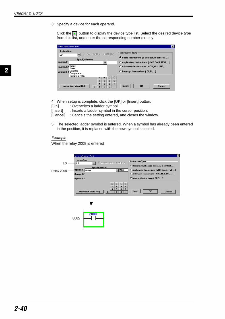
Chapter 2 Editor
2-40
2
3. Specify a device for each operand.
Click the button to display the device type list. Select the desired device typefrom this list, and enter the corresponding number directly.
4. When setup is complete, click the [OK] or [Insert] button.[OK] : Overwrites a ladder symbol.[Insert] : Inserts a ladder symbol in the cursor position.[Cancel] : Cancels the setting entered, and closes the window.
5. The selected ladder symbol is entered. When a symbol has already been enteredin the position, it is replaced with the new symbol selected.
Example
When the relay 2008 is entered
LD
Relay 2008

Chapter 2 Editor
2-41
12
Entering symbols directlyEdit Symbol Input Symbol Direct Input (Enter)
Instruction words can also be directly entered.When you are familiar with creation of ladder programs and handling of instructionwords, direct input is recommended because it is quicker and more efficient thaninput through the "Enter Instruction Word" window.
To open the dialog box for directly entering instruction words, select "Edit", "SymbolInput" and "Direct Symbol Input" from the menu. The following two methods are alsoavailable for quicker operation.
Select the desired cell using the LEFT, RIGHT, UP and DOWN keys, and then enterthe first character of the instruction word to be entered. You can also press theENTER key when changing an existing input.
The dialog box is opened in which the first character is displayed.
Example
When "A" is entered
Entering symbols in the direct input dialog box
1. Enter an instruction word directly from the keyboard into the text box.
Note 1: Enter an instruction word in mnemonic format, and enter a space betweenthe instruction word and the device name.
LD 0001
Note 2: For LD and LDB, "A" and "B" can be entered instead respectively.LD 0001 → A 0001LDB 0001 → B 0001
2. When input is complete, click the [OK] or [Ins] button.[OK] : Overwrites the existing ladder symbol.[Ins] : Inserts the ladder symbol entered in the cursor position.[Cancel] : Cancels the setting entered, and closes the window.
3. The ladder symbol is entered.
→

Chapter 2 Editor
2-42
2
2.4.2 Deleting symbolsEdit Symbol Input Delete Symbol (Delete)
To delete a symbol, place the cursor in the symbol to be deleted, click it, and thenperform either of the following operations. (This procedure is equivalent in principleto the character deletion procedure.)
• Press the space bar.• Press the Delete key.
(When the Backspace key is pressed, the symbol just before the cursor isdeleted.)
2.4.3 Entering contacts/coils directlyEnter a contact or coil directly in the current cursor position.
Entering a/b contacts Edit Symbol Input a (N.O.) Contact Input (F5)
b (N.C.) Contact Input (Shift + F5) a (N.O.) Contact OR Input (F4) b (N.C.) Contact OR Input (Shift + F4)
To enter a contact, perform the following procedure.
1. Place the cursor in the input position.
2. Select "Symbol Input" from the "Edit" menu, and select the contact type to beentered from the submenu.The corresponding function key can be pressed instead or the correspondingicon can be clicked.
• The "Change Device" dialog box is displayed.
When entering an a contact:
a (N.O.) Contact Input (F5) key button
When entering a b contact
b (N.C.) Contact Input (Shift + F5) keys button
When entering an a contact OR
a (N.O.) Contact OR Input (F4) key button
When entering a b contact ORb (N.C.) Contact OR Input (Shift + F4) keys button
3. Enter a device name directly from the keyboard into the text box.
4. When input is complete, click the [OK] button.When the [Cancel] button is clicked, the setting entered is canceled and thedialog box is closed.
5. The ladder symbol is entered.

Chapter 2 Editor
2-43
12
Entering coils
Edit Symbol Input Coil Input (F7) b (N.C.) Contact Coil Input (Shift +F7)
To enter a coil, perform the following procedure.
1. Place the cursor in the input line.
2. Select "Symbol Input" from the "Edit" menu, and select the coil type to be enteredfrom the submenu.The corresponding function key can be pressed instead or the correspondingicon can be clicked.
• The "Change Device" dialog box is displayed.
When entering a coil : Coil Input F7 key button
When entering the b contact coil : Coil Input Shift + F7 keys button
3. Enter a device name directly from the keyboard into the text box.
4. When input is complete, click the [OK] button.When the [Cancel] button is clicked, the setting entered is canceled and thedialog box is closed.
5 The ladder symbol is entered.
2.4.4 Changing the device at the current cursor positionEdit Change Device at Cursor Position (Esc) Right-click
To change the device at the current cursor position, perform the following procedure.
1. Place the cursor in the device to be changed.
2. Select "Change Device at Current Position" from the "Edit" menu or right-clickmenu or press the Esc key.The "Change Device" dialog box is displayed.
3. Enter a device name directly from the keyboard into the text box.
4. When input is complete, click the [OK] button.When the [Cancel] button is clicked, the setting entered is canceled and thedialog box is closed.
5. The device is changed.
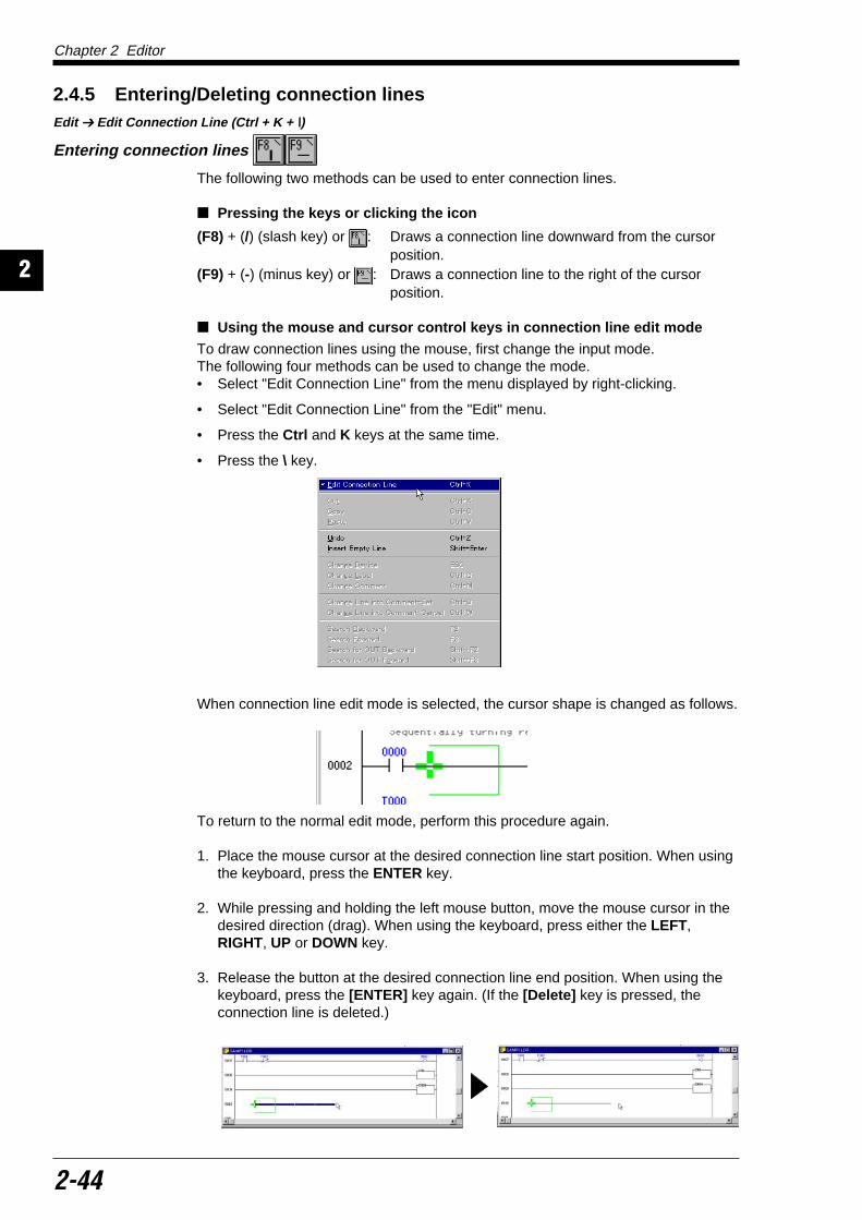
Chapter 2 Editor
2-44
2
2.4.5 Entering/Deleting connection linesEdit Edit Connection Line (Ctrl + K + \)
Entering connection lines
The following two methods can be used to enter connection lines.
Pressing the keys or clicking the icon
(F8) + (/) (slash key) or : Draws a connection line downward from the cursorposition.
(F9) + (-) (minus key) or : Draws a connection line to the right of the cursorposition.
Using the mouse and cursor control keys in connection line edit mode
To draw connection lines using the mouse, first change the input mode.The following four methods can be used to change the mode.• Select "Edit Connection Line" from the menu displayed by right-clicking.
• Select "Edit Connection Line" from the "Edit" menu.
• Press the Ctrl and K keys at the same time.
• Press the \ key.
When connection line edit mode is selected, the cursor shape is changed as follows.
To return to the normal edit mode, perform this procedure again.
1. Place the mouse cursor at the desired connection line start position. When usingthe keyboard, press the ENTER key.
2. While pressing and holding the left mouse button, move the mouse cursor in thedesired direction (drag). When using the keyboard, press either the LEFT,RIGHT, UP or DOWN key.
3. Release the button at the desired connection line end position. When using thekeyboard, press the [ENTER] key again. (If the [Delete] key is pressed, theconnection line is deleted.)

Chapter 2 Editor
2-45
12
Deleting connection lines
To delete a connection line, press the Delete key while dragging the connection lineto be deleted in connection line edit mode.
The following procedures are also available to delete connection lines.
When deleting a vertical connection line
• Press the Shift and F8 keys at the same time.
• While dragging the connection line to be deleted in connection line edit mode,press the Shift key and release the left mouse button at the same time.
• Click the button.
When deleting a horizontal connection line
• Press the space bar.
• Press the Backspace key. (The connection line just before the cursor is deleted.)
• Press the Delete key.
• While dragging the connection line to be deleted in connection line edit mode,press the Shift key and release the left mouse button at the same time.
• Click the button.
2.4.6 Canceling edit operations
Canceling an edit operation (UNDO)
Edit Undo (Ctrl + Z)
The last edit operation (input, move or copy of a symbol) that was performed can becanceled, and the previous status can be recovered.When the last edit operation is unrecoverable and the undo operation is disabled,the selection item "Undo" is shown in a lighter color to indicate the selection isdisabled.
Unrecoverable operations
• Replacement of operands
• Conversion of N.O./N.C. contacts
• Read/save of programs, mnemonic files, etc.
• Change of labels or comments
• Input of macros
Canceling an undo operation (REDO)
Edit Redo (Ctrl + Y)
The last undo operation that was performed can be canceled.When the last undo operation cannot be canceled, the selection item "Redo" isshown in a lighter color to indicate the selection is disabled.

Chapter 2 Editor
2-46
2
2.5 Entering Comments/LabelsThis section describes how to enter comments/labels to contacts, how to changethese comments/labels, and how to enter/change line comments.
2.5.1 Editing comments/labelsThe label name, comment 1, comment 2, and comment 3 can be entered for acontact.Comments are entered so that the contents of a contact can be easily deducedwhen editing a ladder diagram. Comments are displayed in the ladder diagrammonitor, the simulator and the monitor.
Manipulate the "Edit Comment/Label" dialog box. This dialog box is displayed foreach device type, and allows you to edit two or more comments at a time.The label name and comment can also be changed by selecting the device to bechanged in the ladder diagram. Making changes directly in the ladder diagram (p. 2-49)
The comment/label edit method is described below.
Note: The comment 2 and comment 3 files are dedicated to the Ladder Builder forKV. When the comment is to be shared with the KV IncrediWare (DOS), use com-ment 1.
Editing the list for each device Comment Edit Comment/Label (Ctrl + F7)
1. Select "Edit Comment/Label" from the "Comment" menu, or click the button.
The "Edit Comment/Label" dialog box is displayed.The relays 0000 to 0415 are displayed by default.
The "*" symbol is displayed beside devices used in the ladder diagram.
2. Select the device to be edited in the "Reading Device" area.
3. Specify the device range to be displayed in the list in the "Device Range" area.
Reading deviceselection area
Label/commentinput area
Device list displayarea

Chapter 2 Editor
2-47
12
4. Click and select the device for which a label/comment is to be edited, and thenclick the [Edit] button. (Or the desired device displayed in the list can be clickedand selected.)When using the keyboard, select the desired device using the UP and DOWNkeys, and press the ENTER key.
The cursor is displayed in "Label Name" in the label/comment input area so thatcharacters can be entered.
5. Enter or change the label/comment. A label/comment can be copied from orexchanged with another device.
• The table below shows the available character types and the maximum numberof characters allowed.
To register basic relays, click the [Register Basic Relay] button in the "Edit Com-ment/Label" dialog box, and then enter the basic relays of the model used intocomment 1.
6. When input is complete, click the [Write] button.To close the "Edit Comment/Label" dialog box, click the [Exit] button.
The label/comment is entered.
To display labels/comments, select the "View" menu. When the submenu is dis-played, select "Show Label" or "Show Comment". For the method to specify the comment to be displayed, refer to the display mode (p. 2-19).
Note: A label name can be used instead of a device name when entering, searchingfor or replacing a symbol.
For example, when the label "SW1" is attached to the device "0000", the programcan be written as follows.
Instead of entering "0000" : SW1Instead of entering "LD0000" LD: SW1
Labels cannot be entered in the instruction selection window.
Label name Alphabet. 8 characters maximum.Spaces and commas cannot be entered.
Comment 1 32 characters maximum(This comment is compatible with KV IncrediWare (DOS) relay comments.)
Comment 2 32 characters maximum
Comment 3 32 characters maximum

Chapter 2 Editor
2-48
2
When selecting the devices to be displayed in the listThe devices to be displayed in the list can be selected by checking the followingitem.
Show Registered Device Only: Displays the devices in which labels/comments areregistered.
Show Using Device Only: Displays the devices used in the ladder diagram.
When neither item is checked, all the devices are displayed.
When copying a label/comment from another device
1. Place the cursor in the copy source device, and click the [Copy] button.
2. Place the cursor in the copy destination device, and click the [Write] button.When the [Exchange] button is clicked instead of the [Write] button, the contentsof the input area are exchanged with the comments of the selected device.
When deleting registered labels/comments
To delete only the selected device, place the cursor in the device to be deleted, andpress the Delete key or click the [Delete Selected Line] button.
To delete all of the devices, click the [Delete All] button.
When copying a comment block from other devices
1. Select the comment range of the device to be copied as a block in the device listdisplay area. Selecting the range (p. 2-52)
2. Click the [Block Edit] button.The "Block Edit" dialog box is displayed.
3. Select the comment type to be copied by selecting the corresponding radiobutton.
4. Click the [Copy] button.
5. Specify the start device in the copy destination device range in the device listdisplay area.
6. Click the [Block Edit] button.The "Block Edit" dialog box is displayed.
7. Click the [Paste] button.The contact comments in the device range covering the number of devicesspecified in step 1, starting from the device number selected in step 5 are copied.
Radio buttons

Chapter 2 Editor
2-49
12
When moving a comment block from other devicesPerform steps 1 to 7 described above. However, click the [Cut] button instead of the[Copy] button in step 4.Using this procedure, the comment block of the selected devices can be moved.
When deleting a comment block from other devices
Perform steps 1 to 4. However, click the [Cut] button in step 4.Using this procedure, the comment block of the selected devices can be deleted.
Making changes directly in the ladder diagramComment Change Label Name of Current Device (Ctrl + B)
Change Comment of Current Device (Ctrl + M)
Perform the following procedure when entering a label name or comment in theladder diagram.
1. Place the cursor in the device to be entered.
2. When entering a label name, select "Change Label Name of Current Device Ctrl+ B" from the "Comment" menu.
When entering a comment, select "Change Comment Name of Current DeviceCtrl + M" from the "Comment" menu.
The "Change Label" or "Change Comment X" dialog box is displayed.
The dialog box name in which comments can be changed varies depending onthe comment type selected in "Comment Type" in "Display Mode".
When a label name or comment has already been registered in the device, theregistered character string is displayed.
3. Enter the desired character string.The comment selected in "Comment Type" in "Display Mode" can be entered. Display mode (p. 2-19)
4. The displayed character string is entered when the [OK] button is clicked.To cancel the input, click the [Cancel] button.
* Example: When "Comment 2" is displayed in "Comment Type"

Chapter 2 Editor
2-50
2
2.5.2 Editing line comments Comment Edit Line Comment (Ctrl + Enter)
A line comment can be described in each line of the ladder diagram.Line comments are entered so that the contents of each circuit block can be easilydeduced when editing the ladder diagram. Line comments are displayed in theladder diagram monitor, the simulator and the monitor.
To enter a line comment or change a comment, perform the following procedure.
1. Place the cursor in the line for which a line comment is to be entered/changed.When changing a comment that has already been entered, double-click thecomment. The "Enter Line Comment" dialog box is then displayed.
2. Select "Edit Line Comment" from the "Comment" menu, or click the button. The "Enter Line Comment" dialog box is displayed.
3. Enter or change the comment.Up to 70 characters can be entered.
4. When the [Insert] button is clicked, a new line is inserted.When the [Overwrite] button is clicked, a new line is written over the current line.To cancel, click the [Cancel] button.
The entered comment is displayed in the ladder diagram.
Note 1: When the [Overwrite] button is clicked, the portion of the ladder diagramlocated in the cursor line is deleted. Make sure it is okay to delete the correspondingportion of the ladder diagram before clicking the [Overwrite] button.
Note 2: Line comments cannot be transferred to the PLC. Accordingly, line com-ments are not included in a program read from the PLC.
Line comment

Chapter 2 Editor
2-51
12
2.5.3 Changing ladder lines into commentsComment Change Ladder Line into Comment Settings (Ctrl + Q) Right-click
Change Ladder Line into Comment Cancel (Ctrl + W) Right-click
When you specify a ladder line to be treated as a comment, only this specifiedportion is ignored during conversion. Set this function temporarily when you do notwant a certain portion to be converted.To set ladder lines to be changed into comments or to reverse this setting, performthe following procedure.
1. Select the range of the ladder lines to be changed into comments or for which thesetting is to be reversed. Selecting the range (p.2-52)
2. To set the line range to be changed into comments, select "Comment", "ChangeLadder Line into Comment and Settings Ctrl + Q" from the menu or right-clickmenu. To cancel the setting, select "Cancel Ctrl + W" from the submenu.
3. The selected line range is changed into comments.When the setting is canceled, the specified range can be converted.
Note 1: The ladder lines set to be changed into comments cannot be transferred tothe PLC. Accordingly, the ladder lines set to be changed into comments are notincluded in a program read from the PLC.
Note 2: The ladder lines set to be changed into comments cannot be read by the KVIncrediWare (DOS). Accordingly, when a program is read by the KV IncrediWare(DOS) and saved with the same name, the ladder lines set to be changed intocomments are deleted.

Chapter 2 Editor
2-52
2
2.6 Edit and ArrangementThis section describes ladder diagram edit procedures, such as copy/movement/deletion of the range selected in the ladder diagram, insertion/deletion of lines, howto change the number of columns, arrangement of circuits, etc.
2.6.1 Copy, move, and deleteCopy, move or delete the range selected in a ladder diagram.To copy, move or delete the selected range, use the "cut & paste" method which is astandard Windows editing procedure.
Selecting the range
To copy, move or delete data, first select the range. The range can be selectedusing the mouse or keyboard.
Note: Copy, move and delete functions cannot be performed while in connectionline edit mode. If connection line edit mode is selected, select "Edit Connection Line"from the "Edit" menu, and select the normal edit mode (in which the check mark isnot added).
Selecting the range using the mouse
1. Place the mouse pointer in the selection start position, and click.The cursor is displayed.

Chapter 2 Editor
2-53
12
2. While pressing and holding the left button, move the pointer to the selection endposition (drag).
The selected range is displayed in yellow.
• Selecting the range in units of cellsWhile dragging the mouse pointer, move it in the horizontal direction up to thetarget cell until the desired range is selected.
• Selecting the range in units of lines
While dragging the mouse pointer, move it in the vertical direction up to the targetline until the desired range is selected.
Note: A portion of a cell covering two or more lines cannot be selected.
3. Release the left button in the selection end position.To cancel the selection, click anywhere in the ladder diagram.
Selecting the range using the keyboard
1. Place the cursor in the selection start position using the LEFT, RIGHT, UP andDOWN keys.
2. While pressing and holding the Shift key, press the LEFT, RIGHT, UP or DOWNkey, and move the cursor to the selection end position.
The selected range is displayed in yellow.
Note: A portion of a cell covering two or more lines cannot be selected.
3. Release the [Shift] key in the selection end position.
To cancel the selection, press the LEFT, RIGHT, UP or DOWN key again.
Note: When the range is selected in units of cells from the right to the left, the cell atthe left end cannot be selected. When the range is selected in units of lines in anupward direction, the line at the top end cannot be selected.

Chapter 2 Editor
2-54
2
Copy/move/delete operation Edit Cut (Ctrl + X) Right-click
Copy (Ctrl + C) Right-click Paste (Ctrl + V) Right-click
1. After selecting the desired range, perform the following procedure.
When copying data
Perform any of the following operations.
• Select "Copy" from the "Edit" menu on the tool bar, or select "Copy" from theright-click menu.
• Click the button.
• While pressing and holding the Ctrl key, press the C key.
When copying data from another fileWhen two or more windows are open, the desired range can be selected on anotherfile window, and then copied or moved to the current window.
1. Click the copy source window to set it as the current window.
2. Select the desired range, and copy it.
3. Click the copy destination window to set it as the current window.
4. Perform the paste operation. Step 3 on page 2-56.

Chapter 2 Editor
2-55
12
When moving/deleting dataPerform any of the following operations.
• Select "Cut" from the "Edit" menu on the tool bar, or select "Cut" from the short-cut menu displayed by right-clicking.
• Click the button.
• While pressing and holding the Ctrl key, press the X key.
2. Perform the following procedure when copying or moving data.
When pasting data to a ladder diagram
Place the mouse pointer in the copy destination or the move destination, then clickit. You can also move the cursor to the copy destination or the move destinationusing the LEFT, RIGHT, UP and DOWN keys.

Chapter 2 Editor
2-56
2
3. Perform any of the following operations.• Select "Paste" from the "Edit" menu on the tool bar, or select "Paste" from the
shortcut menu displayed by right-clicking.
• Click the button.
• While pressing and holding the Ctrl key, press the V key.
• While pressing and holding the Shift key, press Insert key.
The selected range is pasted.
Note 1: The cut portion is temporarily copied to the cut buffer. Accordingly, even ifthe portion is cut to be deleted, the cut portion can be pasted again by performingstep 3 above.
Note 2: When the number of cells copied is larger than the paste destination space,the message "Can’t write at current position." is displayed, and the cells equivalentto only the paste destination space are pasted. The remaining cells are not pasted.

Chapter 2 Editor
2-57
12
2.6.2 Inserting and deleting linesTo insert lines into a ladder diagram or delete existing lines, perform the followingprocedure.
Inserting blank linesEdit Insert Empty Line (Shift + Enter) Right-click
1. Place the cursor in the position at which blank lines are to be inserted.
To insert two or more blank lines at once, first select the insertion range. Then,the selected blank lines can be inserted all at once.
2. Select "Insert Empty Line" from the "Edit" menu or right-click menu, or press theENTER key while pressing and holding the Shift key.
Blank lines are inserted above the cursor.
Deleting linesEdit Delete Line (Shift + Delete)
1. Place the cursor in the line to be deleted.
To delete two or more lines at once, first select the deletion range.
2. Select "Delete Line" from the "Edit" menu, or press the DEL key while pressingand holding the Shift key.
The specified lines are deleted.

Chapter 2 Editor
2-58
2
2.7 Jump, Search, and ReplaceThis section describes how to jump to any position in a ladder diagram, search foran instruction word/operand, and replace operands or N.O./N.C. contacts.
2.7.1 JumpThe edit control can jump to any position by specifying the desired line number orstep number of the program. The edit control can also be jumped to the first or lastline. Use the jump function to quickly change the edit position.
Jump to the specified line/stepEdit Jump Line/Step No.
To jump to another position by specifying the desired line number or step number ofthe ladder program, perform the following procedure.
1. Select "Edit", "Jump," and "Line/Step No." from the menu. You can also enter thedesired line number or step number directly from the keyboard.
The "Jump to Specified Line" dialog box is displayed.
2. Specify the line number or step number as the jump destination.When a line number or step number is entered from the keyboard in step 1, it isalready specified.
3. Click the [Line] button when jumping the edit control by specifying a line number.Click the [Step] button when jumping the edit control by specifying a step num-ber.Click the [Cancel] button to cancel jumping.
The specified line or step is displayed, and the cursor is moved to the specifiedline or step.
Note: When a number larger than the last line or step number is selected, the lastline or step is displayed.

Chapter 2 Editor
2-59
12
Jump to the first/last lineEdit Jump Top (Ctrl + Home)
Bottom (Ctrl + End)
To jump to the first line or the last line of a ladder diagram, perform the followingprocedure.
When jumping to the first lineSelect "Edit", "Jump" and "Top" from the menu.
When jumping to the last line
Select "Edit", "Jump" and "Bottom " from the menu.
Jump to the registered lineEdit Jump Line Registration (Ctrl + L)
Registered Line (Ctrl + J)
The desired lines can be temporarily registered together with comments, and theedit control can be jumped by specifying the jump destination from the registeredline list.This function is useful when a jump to the same line is performed many times orwhen the line number does not help you recognize the line.
Registering lines
Register lines using the following procedure.
1. Place the cursor in the line to be registered.
2. Select "Edit", "Jump" and "Line Registration" from the menu.
The "Line Registration" dialog box is displayed.
3. Enter the desired comment for the line to be registered into "Comment" if neces-sary.When registering the same comment for another line, change "Line No." to theline number to be registered.
Up to 70 characters can be entered.

Chapter 2 Editor
2-60
2
4. Click the [Register] button when registering the specified line.Click the [Cancel] button to cancel registration.
The specified line is registered.
Note: Up to 32 lines can be registered. When the number of registered lines ex-ceeds 32, lines are deleted beginning at the oldest one.
Jump to a registered line
To jump to a registered line, perform the following procedure.
1. Select "Edit", "Jump" and "Registered Line" from the menu.
The "Jump to Registered Line" dialog box is displayed.
2. Position the pointer over the jump destination line in the line No./comment listdisplayed, and then click it. Double-click it to jump immediately.
3. Click the [Jump] button.To cancel jumping, click the [Cancel] button.
The specified line is displayed, and the cursor is moved to the specified line.
Deleting a registered line
Place the cursor in the line to be deleted in the "Jump to Registered Line" dialogbox, and click the [Delete Registration] button. The specified line is deleted.
Note 1: Set registration for each ladder program window.
Note 2: When a file is saved, data on registered lines is also saved.
Note 3: When data is saved by the KV IncrediWare (DOS), registration becomesinvalid.

Chapter 2 Editor
2-61
12
Jump to the next/previous blockEdit Jump Next Block (Ctrl + DOWN)
Previous Block (Ctrl + UP)
To jump to the next circuit block or to the previous circuit block from the currentcursor position, perform the following procedure.
Jump to the next circuit block
• Select "Edit", "Jump" and "Next Block" from the menu.• Press the DOWN key while pressing and holding the Ctrl key.
Note: Jump from a comment line to the next circuit block is disabled.
Jump to the previous circuit block
• Select "Edit", "Jump" and "Previous Block" from the menu.• Press the UP key while pressing and holding the Ctrl key.
Jump to the beginning/end of the lineEdit Jump Beginning of Line (Home)
End of Line (End)
To jump to the beginning or end of the line in which the cursor is currently placed,perform the following procedure.
Jump to the beginning of a line
• Select "Edit", "Jump" and "Beginning of Line" from the menu.
• Press the Home key.
Jump to the end of a line• Select "Edit", "Jump" and "End of Line" from the menu.
• Press the End key.
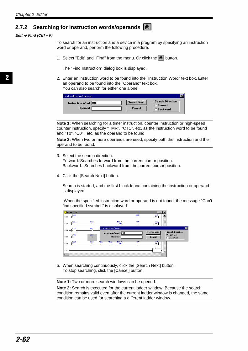
Chapter 2 Editor
2-62
2
2.7.2 Searching for instruction words/operands Edit Find (Ctrl + F)
To search for an instruction and a device in a program by specifying an instructionword or operand, perform the following procedure.
1. Select "Edit" and "Find" from the menu. Or click the button.
The "Find Instruction" dialog box is displayed.
2. Enter an instruction word to be found into the "Instruction Word" text box. Enteran operand to be found into the "Operand" text box.You can also search for either one alone.
Note 1: When searching for a timer instruction, counter instruction or high-speedcounter instruction, specify "TMR", "CTC", etc. as the instruction word to be foundand "T0", "C0" , etc. as the operand to be found.
Note 2: When two or more operands are used, specify both the instruction and theoperand to be found.
3. Select the search direction.Forward: Searches forward from the current cursor position.Backward: Searches backward from the current cursor position.
4. Click the [Search Next] button.
Search is started, and the first block found containing the instruction or operandis displayed.
When the specified instruction word or operand is not found, the message "Can’tfind specified symbol." is displayed.
5. When searching continuously, click the [Search Next] button.To stop searching, click the [Cancel] button.
Note 1: Two or more search windows can be opened.
Note 2: Search is executed for the current ladder window. Because the searchcondition remains valid even after the current ladder window is changed, the samecondition can be used for searching a different ladder window.

Chapter 2 Editor
2-63
12
2.7.3 Searching for the device at the cursor positionEdit Find Device at Cursor Position in Ladder Search Backward (U) (F2)
Search Forward (F3) Search for OUT Backward (Shift + F2) Search for OUT Forward (Shift + F3)
To search for the device equivalent to the device at the current cursor position,perform the following procedure.
1. Place the cursor in the device to be found.
2. Select "Find Device at Cursor Position in Ladder" from the "Edit" menu.
3. Select the search direction.Search Backward : Searches backward from the current cursor position.Search Forward : Searches forward from the current cursor position.Search for OUT Backward : Searches for OUT backward from the current cursor
position.Search for OUT Forward : Searches for OUT forward from the current cursor
position.
4. Search is started, and the first device found is displayed.
5. When searching continuously, repeat steps 2 to 4 above.

Chapter 2 Editor
2-64
2
2.7.4 Replacing operands Edit Replace Operand (Ctrl + R)
When replacing an operand by specifying the replacement range and the replace-ment width, perform the following procedure.
1. Select "Replace Operand" from the "Edit" menu, or click the button.
The "Replace Operand" dialog box is displayed.
2. Enter the operand before replacement into the "Before Replacement" text box.Enter the operand after replacement into the "After Replacement" text box.
3. Enter the replacement width.
What is the replacement width?The replacement width indicates how many operands are to be treated as thereplacement target.For example, when "3" is set while replacing "3000" with "0500", "3000" to "3002"will be replaced with "0500" to "0502".
4. Specify the replacement range using the line number. By default, all the lines arereplaced (from the first line to the last line).
5. Specify the replacement method. Add a check mark to the desired method byclicking it.
6. To execute replacement, click the [OK] button. To cancel replacement, click the[Cancel] button.
The operand set to the "Before Replacement" text box is indicated with the greycursor, and the confirmation message "Replace this operand?" is displayed.
Replace All without Check The message to confirm execution of replacement isnot displayed at all.
Show Can’t Replace Message For an operand which cannot be replaced, the message is displayed.
Move Comment and Label The comment and the label attached to the operandbefore replacement are attached to the operand afterreplacement.

Chapter 2 Editor
2-65
12
7. Click the [Yes] button to execute replacement.Click the [No] button not to execute replacement.Click the [Cancel] button to cancel replacement.
The operand indicated with the brown cursor is replaced with the operand set tothe "After Replacement" text box.
Note 1: When "Replace All without Check" is selected, the confirmation message isnot displayed.
Note 2: When "Move Comment and Label" is selected, all the comments of thedevices in the set range are replaced. For example, when "0000" is replaced with"0010", the "0000" comment is deleted, and the "0010" comment replaces it.
8. When all replacements are complete, the number of operands replaced is dis-played.Click the [OK] button.
2.7.5 Converting a/b contactsEdit Convert a-b (N.O.-N.C.) Contacts (Ctrl + A)
To convert an a (N.O.) contact into a b (N.C.) contact or to convert a b (N.C.) con-tact into an a (N.O.) contact, perform the following procedure.
1. Select "Convert a-b (N.O.-N.C.) Contacts" from the "Edit" menu.
The "Convert a-b (N.O.-N.C.) Contacts" dialog box is displayed.
2. Enter the operand to be converted. Click "Convert All without Check" to attachthe check mark so that the message to confirm execution of conversion is notdisplayed.

Chapter 2 Editor
2-66
2
3. To execute conversion, click the [OK] button.To cancel conversion, click the [Cancel] button.
The specified operand is indicated with the grey cursor, and the confirmationmessage "Covert this contact?" is displayed.
Note : When "Convert All without Check" is selected, the confirmation message isnot displayed.
4. Click the [Yes] button to execute conversion.Click the [No] button not to execute conversion.Click the [Cancel] button to cancel conversion.
The a (N.O.) contact is converted into a b (N.C.) contact. The b contact is con-verted into an a contact.
5 When all conversions are complete, the number of contacts converted is dis-played.Click the [OK] button.

Chapter 2 Editor
2-67
12
2.8 Editing the Mnemonic ListThis section describes how to display each block of circuit in a ladder diagram as amnemonic list, and how to edit the mnemonic language directly.
2.8.1 Displaying and terminating a mnemonic list
Displaying a mnemonic list
Edit Edit List
To display mnemonic lists by specifying blocks and to enter symbols by editingmnemonic lists, perform the following procedure.
1. Place the cursor in the block for which a mnemonic list is to be displayed or inwhich the edit contents of the mnemonic list are to be inserted/replaced.
In the case of insertion, the edit contents are inserted above the cursor line.
2. Select "Edit List" from the "Edit" menu, or click the button.
The mnemonic list of the block at the cursor position is displayed on the list editwindow.
The mnemonic language can be directly edited on this screen.For a compiled block, step numbers are displayed.When entering a new mnemonic, a step number and comment do not have to beentered. For the compilation procedure, refer to "2.12 Compilation" on page 2-75.

Chapter 2 Editor
2-68
2
Terminating a mnemonic list
Inserting the mnemonic list edited into the cursor position, and terminatingedits
When edits are complete, click the [Insert] button.
The list edit window is closed, and the edit contents are inserted at the cursorposition in the ladder diagram.
Replacing the block in the cursor position with the mnemonic list edited,and terminating edits
When edits are complete, click the [Replace Blocks] button.
The list edit window is closed, and the block at the cursor position in the ladderdiagram is overwritten with the edit contents.
Format of a mnemonic list
The following format is used in a mnemonic list.Keep in mind that compilation is disabled if the format is different.
Note 1: Comments cannot be edited in a mnemonic list.
Note 2: Step numbers and comments do not have to be entered while editing amnemonic list.
;
Step No. Mnemonic
2 spaces 2 spaces
Operand
2 spacesSemicolon
Comment

Chapter 2 Editor
2-69
12
2.8.2 Copy, move, and deleteCopy, move and delete in a mnemonic list can be performed using the "cut & paste"operation in the same way as in a ladder diagram.
1. Place the cursor in the start position of the copy/move/delete range.
2. While pressing and holding the [Shift] key, move the cursor to the end position ofthe range using the UP and DOWN keys.
The selected range is displayed in blue.
3. Release the key when in the end position.
When canceling the selection, press the UP or DOWN key without pressing andholding the [Shift] key.
4. Perform the cut, copy or paste operation using the shortcut keys. Copy/move/delete operation (p. 2-54)
Cut [Ctrl] + [X] : Cuts the selected range.Copy [Ctrl] + [C ] : Copies the selected range.Paste [Ctrl] + [V] : Pastes the cut or copied range.
Note: In Windows 95, the mouse (right-click) can be used instead of the keys.

Chapter 2 Editor
2-70
2
2.9 Displaying the Use StatusThis section describes how to display the list of relays, timers, counters, compara-tors, data memory and temporary memory used in the program while editing aladder diagram.
2.9.1 Displaying a use status list
Displaying the use status Edit Usage Information
To display lists of relays, timers, counters, comparators, data memory and tempo-rary memory used in the program while editing a ladder diagram, perform the follow-ing procedure.
1. Select "Usage Information" from the "Edit" menu, or click the button.
The "Usage Information" dialog box is displayed.
2. Select the item to be checked from "Type". The use status list is then displayed.
3. You can edit ladder diagrams while checking the use status list on the display. Toreflect the latest use status for the ladder diagram being created, click the[Update(U)] button.
4. To close the use status list, click the [Close(C)] button.

Chapter 2 Editor
2-71
12
2.10 Setting the SystemThis section describes how to set the directory used for the auto save function, andhow to select the decompilation error check.
2.10.1 Setting the systemEdit System Settings
To set the directory used for the auto save function and to select the decompilationerror check, perform the following procedure.
1. Select "System Settings" from the "Edit" menu.
The "System Settings" dialog box is displayed.
When setting the work directory used for the automatic save functionSpecify the directory (folder) used for the automatic save function as "WorkDirectory" using a full path.
When selecting the decompilation error checkClick the "Code Check" check box to add a check mark. Decompilation errors willthen be automatically checked when a ladder program is compiled.If an error is detected, the message "Reverse Compile Error" is displayed whencompilation is complete.
H.3 Programs which cannot be decomplied (Appendices p. 2-203)
The code check is specified by default.When the deconversion error check is not required, delete the check mark.
Note: When the code check is specified, the compilation time is longer because aprogram in which errors will be detected during decompilation and whose transferwill be aborted is checked while the program is transferred from the KV main body tothe personal computer.

Chapter 2 Editor
2-72
2
2.11 Entering and Developing MacrosThe Ladder Builder for KV is equipped with a macro function. By using macros,programs in which the same process is repeated many times and for which there areextended instructions can be entered efficiently. The Ladder Builder for KV isequipped as standard with the macro file to enter frequently used circuits.
2.11.1 Creating a macro fileTo use a macro, first create a macro file saving the contents to be processed in themacro.To create a macro, perform the following procedure.
1. Select "New" from the "File" menu, and open a new ladder program window inaccordance with the model.
2. Place the cursor in the first line. Select "Edit Line Comment" from the "Comment"menu.
The "Enter Line Comment" dialog box is displayed.
3. In the first line, enter the macro name, the number of arguments and the com-ment in the following format as the macro start declaration line.
@ Macro name, Number of arguments, Comment
Include "@" at the beginning.
@TEST.4.test macro
Number ofarguments
Comment
Macro name Enter up to 8 characters. Do not enter spaces.
Number of arguments Enter the number of devices to be variable. Temporarydevices (shown below) contained in a ladder diagram can bereplaced with arbitrary devices (up to 10 devices).
Comment Enter a comment on an argument, etc.
→
Separate each item with a comma (,).

Chapter 2 Editor
2-73
12
4. Under the macro start declaration line, enter the symbol to be processed by themacro. At this time, describe the devices to be treated as arguments as tempo-rary devices.
What are temporary devices?Temporary devices indicate devices described temporarily when actual devicesare not yet determined. Up to 1,000 temporary devices from "@0" to "@999" canbe described. Each temporary device will be automatically replaced while amacro is developed.
Note: Up to 10 devices from "@0" to "@9" can be used in each macro. When usingthem, make sure to assign temporary devices sequentially starting from "@0".
5. In the last line, enter two "@" symbols from "Edit Line Comment" as the macroend declaration line.
Example
Macro which writes data (constant) to the DM0000 when three relays are turned on(Four arguments are used.)
6. Two or more macros can be described in one macro file. When describinganother macro, repeat steps 3 to 5 above.
Note: Make sure to describe each macro in the portion between the macro startdeclaration line and the macro end declaration line.
7. Select "Save As" from the "File" menu, and save the file with the desired macrofile name. The extension of the file name is "ldr" which is the same as the exten-sion for a ladder program.
Creation of the macro file is now completed.The Ladder Builder for KV is equipped with the macro file "IMACRO.LDR" to enterfrequently used circuits. Use this file when entering circuits.
Note 1: The macro start declaration line is entered as a line comment. Enter up to70 characters.
Note 2: Timer/counter instructions cannot use temporary devices.
Macro startdeclarationline
Macro
Macro enddeclarationline
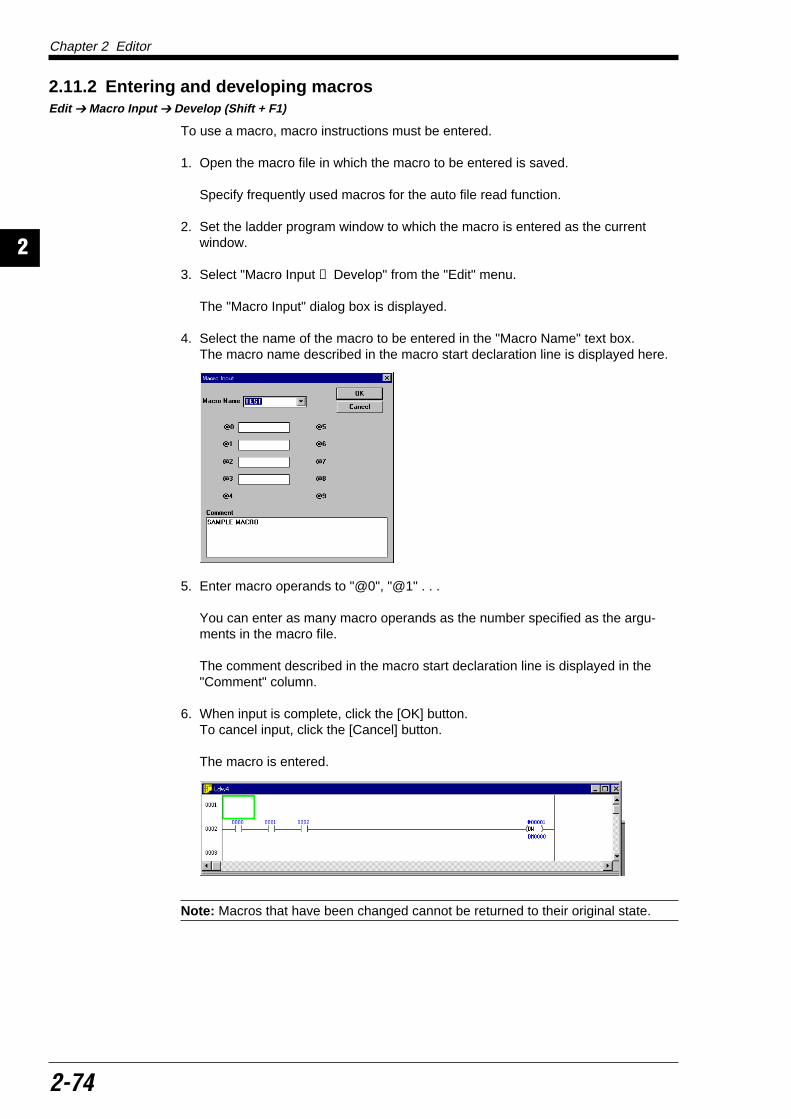
Chapter 2 Editor
2-74
2
2.11.2 Entering and developing macrosEdit Macro Input Develop (Shift + F1)
To use a macro, macro instructions must be entered.
1. Open the macro file in which the macro to be entered is saved.
Specify frequently used macros for the auto file read function.
2. Set the ladder program window to which the macro is entered as the currentwindow.
3. Select "Macro Input → Develop" from the "Edit" menu.
The "Macro Input" dialog box is displayed.
4. Select the name of the macro to be entered in the "Macro Name" text box.The macro name described in the macro start declaration line is displayed here.
5. Enter macro operands to "@0", "@1" . . .
You can enter as many macro operands as the number specified as the argu-ments in the macro file.
The comment described in the macro start declaration line is displayed in the"Comment" column.
6. When input is complete, click the [OK] button.To cancel input, click the [Cancel] button.
The macro is entered.
Note: Macros that have been changed cannot be returned to their original state.

Chapter 2 Editor
2-75
12
2.12 CompilationThis section describes how to compile ladder programs created using the editor.
2.12.1 Executing compilation Compile Compile (Ctrl + F9)
Ladder programs created using the editor cannot be transferred to a PLC. Theymust be compiled into machine code.
To compile a ladder program, perform the following procedure.
1. Set the ladder diagram of the program to be compiled as the current window.
2. Select "Compile" from the "Compile" menu, or click the button.The compilation process is performed.
3. When the program is correctly compiled, the message "Compilation successful."is displayed. Click the [OK] button.

Chapter 2 Editor
2-76
2
2.12.2 Error display Compile Show Error (Ctrl + F10)
When an error occurs during compilation, a message is displayed and you canconfirm the contents of the error.
1. When an error occurs, the message "Compilation Error" is displayed.
2. Click the [OK] button.
The error list window is displayed.
3. To jump to the location in the program in which an error has occurred, specify thedesired error and click the [Jump] button.
The error location is displayed.
4. To display the error list again, select "Show Error" from the "Compile" menu, orclick the button.
2.12.3 Double coil check
Double coil checkCompile Check Double Coil
Double coil locations in a ladder program can be checked. (Double coil locations arenot detected as errors during compilation.)
Select "Check Double Coil" from the menu. Double coils are then detected.
Note: The double-coil check uses three instruction words: OUT, DIFU, and DIFD.
Even if double coil locations are not detected by the double coil check, they mayfunction as double coils depending on the assembly of ladder circuits.
Error code Contents

Chapter 2 Editor
2-77
12
2.13 Printing FunctionsThis section describes how to print out ladder diagrams, mnemonic lists, labels/comments/references, device use status, and parameters.
2.13.1 Printing File Print (Ctrl + P)
Connect the personal computer to a printer before starting the printout.
The contents to be printed out must be set before starting the printout.
1. Select "Print" from the "File" menu, or click the button.The "Print Setup" dialog box is displayed.
2. You can select whether or not each item is printed. Click "Yes" to print the item,and click "No" not to print the item."Yes" is selected only for ladder diagrams by default.
The following four items can be printed out.• Ladder diagrams• Mnemonic lists• Labels/comments/references• Device use status
3. The printout range can be set for each item. Set the range in the dialog boxdisplayed when the [Detail] button is clicked.
For the setup procedure for each item, refer to page 2-78.
4. Click the [OK] button to start printing.Click the [Cancel] button to cancel printing.
Note 1: If the settings are changed, the changes are not saved if the [Cancel] buttonis clicked.
Note 2: When "Show in XYM" and "Show Decimal Constant with Sign" are selectedin the display mode, printout is performed according to the setting. Display mode (p. 2-19)

Chapter 2 Editor
2-78
2
Ladder diagram (details)
Example of printout
Mnemonic list (details)
Example of printout
Item Setting contents (input range) Initial value
Print Start Line No. Line number from which printout is started 1
Print Finish Line No. Line number at which printout is ended Last line on editscreen
No. of Lines in Page Number of lines printed on one page (5 to 50) 20
Print Comment Comment 1, Comment 2, Comment 3, or No No
Print Device Device Name or Label Name Device Name
Divide Block Consider (divided) or Ignore (not divided) Consider
Item Setting contents (input range) Initial value
Print Start Step Step number from which printout is started 0
Print Finish Step Step number at which printout is ended 65534
No. of Lines in Page Number of lines printed on one page (30 to 120) 60
Print Comment Comment 1, Comment 2, Comment 3, or No No
Print Device Device Name or Label Name Device Name
0000
0001 ** **
0002
0003
0004
0005
T 000
L0002 (A)L0006 (A)
L0005 (%)
L0006 (A)L0007 (A)
L0008 (%)
L0007 (A)
$00024
T000T 001
$00020
T001T 002
$00054
0000 T000
Name : SAMP01.LDR (KV10) LADDER Date : 1997/09/06 Page (1/1)
0000000100020003000400050006000700080009000100001100012 •00013
LDMPSCTCCONCTCCONCTHMPPCTCCONCTCCONCTH
LD
2002
1
0
0
2
3
1
2008
#020
#255
2101
#65535
#65535
0500
** **
** **
Name : TRST02 LDR (KV01) LIST Date : 1997/08/22 Page (1/3)

Chapter 2 Editor
2-79
12
Item Setting contents (input range) Initial value
No. of Lines in Page Number of lines printed on one page (30 to 120) 70
Print References Yes or No No
Item Input range (initial value)
Relay Available range according to the model
Timer
Counter
High-Speed Counter –
Comparator –
Data Memory Available range according to the model
Temporary Memory –
< ><N0.> <Label> <Comment1> <Comment2> <Comment2>0000 : SWO SWITCH SWITCH
L002(A) L0006(A)
0500 : OUTPUT 500L006(OUT)
0501 : OUTPUT 501L008(OUT)
0502 : OUTPUT 502L007(OUT)
Name : SAMP01.LDR (KV10) Date : 1997/09/06 Page (1/1)Label
Labels/comments/references (details)
Add the check mark to the devices to be printed out, and set the printout range.By default, all devices are selected and the entire range is specified.
Example of printout

Chapter 2 Editor
2-80
2
[ ]
0123456789ABCDEF 0123456789ABCDEF 0123456789ABCDEF 0123456789ABCDEF 0123456789ABCDEF
0000–– 0415: X0500–– 0915: XXX1000–– 1415:1500–– 1915:2000–– 2415:2500–– 0915:
Name : SAMP01.LDR (KV10) Date : 1997/09/11 Page (1/5)
Device use status
Add a check mark to the devices to be printed out, and set the printout range.By default, all devices are selected to be printed out.
Example of printout (relay)

Chapter 2 Editor
2-81
12
2.13.2 Preview displayFile (F) Print Preview (V)
To preview on the screen the contents to be printed out, perform the followingprocedure.
1. Select "Print Preview" from the "File" menu.The "Print Setup" dialog box is displayed.
2. Set the contents to be printed out. For the setup procedure, refer to page 2-79.
3. Click the [Execute] button.The actual image to be printed out is displayed.
The [Print] button can be clicked on this screen to print out the contents dis-played.

Chapter 2 Editor
2-82
2
Object screen
Sets the color tint.
Sets the brightness.
2.14 Changing the Display Color on the ScreenIn the Ladder Builder, the color layout of the screen can be changed. This sectiondescribes how to change display colors on the screen.
2.14.1 Changing display colors on the screenView Change Ladder Diagram Color
This function sets the color layout of the Ladder Builder screen.The setup procedure is described below.
1. Select "Change Ladder Diagram Color" from the "View" menu.The "Change Ladder Diagram Color" dialog box is displayed.
The "Color" box provided on the side of each item indicates the color currentlyset.
2. Select the item whose color is to be changed in the "Section to be Specified" textbox, and click the button of "Color".The "Section to be Specified" text box can be set by clicking the desired positionin the diagram displayed on the object screen.
The "Color Setup" dialog box is displayed.
Select the desired color, and click the [OK] button.
You can create an intermediate color by clicking the [Create Color] button.To determine the intermediate color created, click the [Add Color] button.
3. When changes are complete, click the [OK] button.Click the [OK] button to confirm the setting. Click the [Cancel] button to cancelthe setting.
To return the screen colors to the default setting, click the [Back to Initial Setting]button.
Note: When the number of display colors on the screen is set to 256 or less, somecolors may not be displayed correctly.


![C R E D I T S - thetrove.is [multi]/Naruto (d20)/d20-Naruto... · This Naruto: d20 supplement is designed for use with the Naruto d20 and d20 Modern Roleplaying Game published by](https://img.pdfslide.us/doc/110x75/60afa37945ac8908e62fd7cc/c-r-e-d-i-t-s-multinaruto-d20d20-naruto-this-naruto-d20-supplement.jpg)