Embed Size (px)
Citation preview
User’s Manual
General Purpose Input/Output (GPIO) Module

Product Warranty
Printronix warrants that the Products furnished under this Agreement shall be free from defects in material and workmanship for a period of one year from the date of shipment from the Printronix facility. This warranty is applicable only if the products have had normal utilization within the published specifications as modified from time to time, have been maintained in accordance with recommended procedures with Printronix approved parts, and have not been modified or altered in a manner not approved by Printronix.
For printers sold within the area in which Purchaser normally provides field service:
For all printers the Purchaser will provide the end-user with a 90-day on-site warranty. Any printer or part therein found defective within one year of original shipping date from a Printronix facility shall be returned to Printronix and be repaired or replaced at the option and expense of Printronix. Purchaser shall pay shipping cost to the Printronix facility and Printronix will return the item(s) at its expense.
For printers sold outside the area, within the Continental United States, in which Purchaser normally provides field service:
Any printer found defective within 90 days from the date of shipment to the end user will be repaired at the end user’s location. If the end user is located within 100 miles of an Authorized Service Provider’s location, warranty service will be performed at no charge. If the end user is located more than 100 miles from an Authorized Service Provider’s location, travel time and expenses in excess of 100 miles will be billed to the end user at current rates or the printer may be shipped to the nearest Authorized Service Center for repair. If the end user elects to ship the printer for warranty repair, the end user shall pay the shipping cost to the Authorized Service Center and the printer will be returned at Printronix’ expense.
The Products may be equipped with a general purpose input/output circuit board and corresponding pin connection (GPIO) which allow the Purchaser’s or end user’s printer to function as a controller in a computer system. Printronix publishes the specifications associated with GPIO and the pin connection and warrants that the printer’s input and output parameters at the pin connection conform to those specifications. Except as expressly warranted, GPIO is sold on an “as is” basis. There are no other warranties whatsoever, express or implied, concerning GPIO.
Purchaser’s remedies are expressly limited to Printronix’ obligations as stated above, and in no event shall Printronix be held liable for any incidental or consequential damages or loss of use, or other commercial loss, however occasioned.
THE WARRANTIES SET FORTH IN THIS ARTICLE AND THE OBLIGATIONS AND LIABILITIES THEREUNDER ARE IN LIEU OF, AND THE PURCHASER HEREBY WAIVES, ALL IMPLIED GUARANTEES AND WARRANTIES, INCLUDING WITHOUT LIMITATION, ANY WARRANTY OF MERCHANTIBILITY OR FITNESS FOR A PARTICULAR PURPOSE. IN NO EVENT SHALL PRINTRONIX BE HELD LIABLE FOR ANY INCIDENTAL OR CONSEQUENTIAL DAMAGES OR LOSS OF USE, OR OTHER COMMERICAL LOSS, HOWEVER OCCASIONED.
Notice of Copyright
This document contains proprietary information protected by copyright. No part of this document may be reproduced, copied, translated, or incorporated in any other material in any form or by any means, whether manual, graphic, electronic, mechanical, or otherwise, without the written consent of Printronix, Inc.
All non-Printronix registered and/or unregistered trademarks used throughout this manual are the sole property of their respective owners.
Copyright © 2003, 2013 Printronix, Inc. All rights reserved.
Table of Contents
GPIO..................................................................... 7Overview................................................................................................ 7
SL5000r/T5000r Menu Overview........................................................... 8
P7000 Menu Overview .......................................................................... 9
GPIO CONTROL Menu ....................................................................... 10
GPIO CONTROL Menu Items....................................................... 11
Connector Pinout ................................................................................. 14
Signal Descriptions .............................................................................. 14
Outputs.......................................................................................... 14
Inputs ............................................................................................ 16
Power and Grounds ...................................................................... 17
Hardware Specifications ...................................................................... 17
A Inputs And Outputs - Electrical ........................... 21GPIO Opto-coupled Input Circuit ......................................................... 21
GPIO Opto-coupled Output Circuit ...................................................... 21
B Contact Information............................................. 23Printronix Customer Support Center.................................................... 23
Printronix Supplies Department ........................................................... 24
Corporate Offices................................................................................. 24

Table of Contents
GPIO
OverviewThe Printronix General Purpose Input/Output (GPIO) module is an optional accessory for SL5000r/T5000r thermal and P7000 line matrix printers. It enables the printers to interface with an external device such as a label applicator system.
Simple printer menus allow for programming three of the eleven pre-defined interface signals (seven outputs, four inputs) to select particular polarity or logic functions that can meet practically all typical print/apply requirements or be compatible with practically all the features available on other manufacturers’ external I/O interfaces. This allows easy migration of Printronix thermal and line matrix printers to new or existing systems. Field interface is accomplished through an industry standard 50-pin D-type connector.
GPIO is available as a factory option or field installable kit that also includes a mating connector for field interface, installation instructions, and operation manual.
Although there are seven pre-defined outputs and four pre-defined inputs, the GPIO module actually contains a total of eight inputs, eight outputs (all inputs and outputs are optically-isolated), and four relays. By using Printronix GPIO Manager software, these can all be custom configured and be mapped in conjunction with Printronix proprietary functions such as ODV analyses, printer front panel keys, and communications ports to provide powerful functions, including multiple interfaces, previously not attainable with a single accessory module.
7
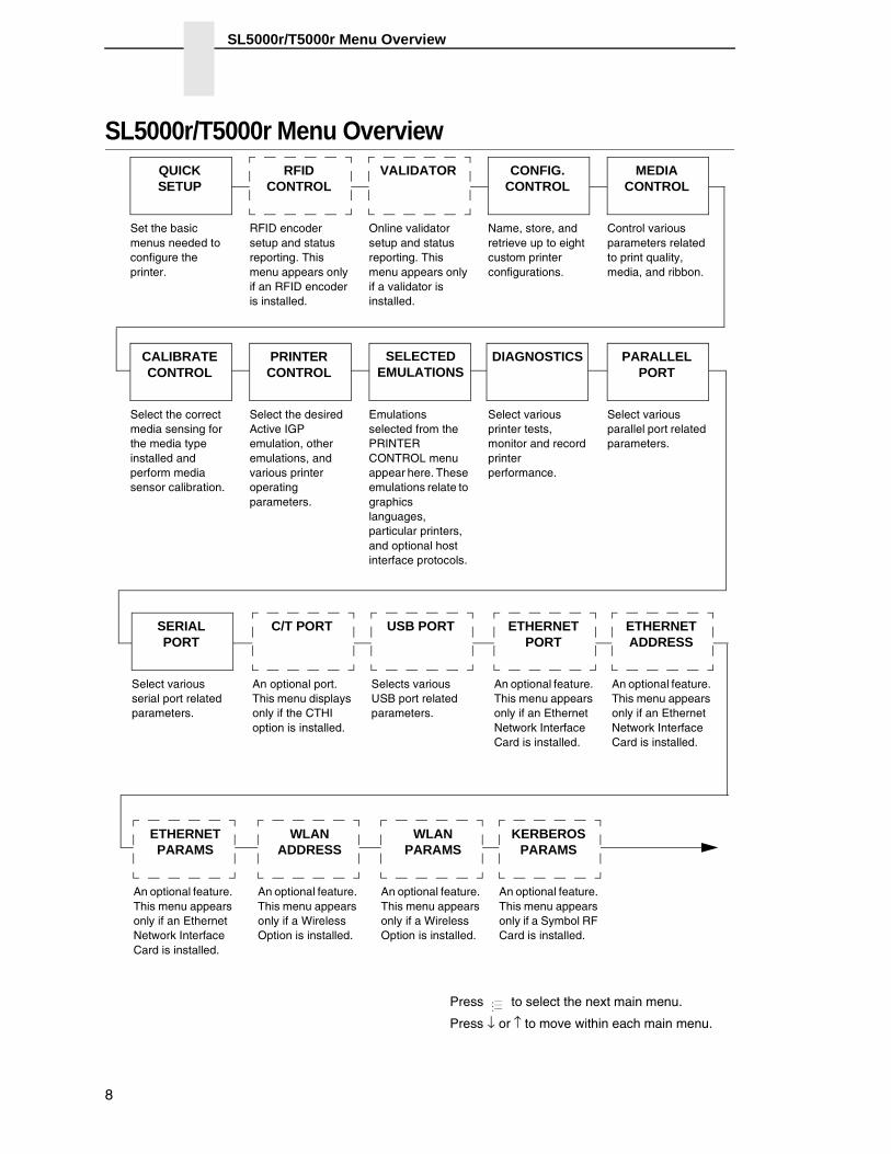
SL5000r/T5000r Menu Overview
SL5000r/T5000r Menu OverviewQUICKSETUP
Set the basic menus needed to configure the printer.
VALIDATOR
Online validator setup and status reporting. This menu appears only if a validator is installed.
CONFIG. CONTROL
Name, store, and retrieve up to eight custom printer configurations.
MEDIA CONTROL
Control various parameters related to print quality, media, and ribbon.
PRINTER CONTROL
Select the desired Active IGP emulation, other emulations, and various printer operating parameters.
Emulations selected from the PRINTER CONTROL menu appear here. These emulations relate to graphics languages, particular printers, and optional host interface protocols.
DIAGNOSTICS
Select various printer tests, monitor and record printer performance.
PARALLEL PORT
Select various parallel port related parameters.
ETHERNET PORT
An optional feature. This menu appears only if an Ethernet Network Interface Card is installed.
ETHERNET PARAMS
An optional feature. This menu appears only if an Ethernet Network Interface Card is installed.
SELECTED EMULATIONS
WLAN ADDRESS
An optional feature. This menu appears only if a Wireless Option is installed.
Press to select the next main menu.
Press ↓ or ↑ to move within each main menu.
...
C/T PORT
An optional port. This menu displays only if the CTHI option is installed.
KERBEROS PARAMS
An optional feature. This menu appears only if a Symbol RF Card is installed.
WLAN PARAMS
An optional feature. This menu appears only if a Wireless Option is installed.
SERIALPORT
Select various serial port related parameters.
CALIBRATE CONTROL
Select the correct media sensing for the media type installed and perform media sensor calibration.
RFID CONTROL
RFID encoder setup and status reporting. This menu appears only if an RFID encoder is installed.
USB PORT
Selects various USB port related parameters.
ETHERNET ADDRESS
An optional feature. This menu appears only if an Ethernet Network Interface Card is installed.
8
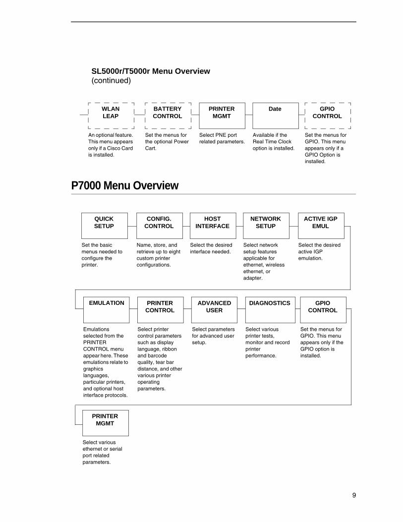
P7000 Menu Overview
GPIO CONTROL
Set the menus for GPIO. This menu appears only if a GPIO Option is installed.
BATTERY CONTROL
Set the menus for the optional Power Cart.
WLAN LEAP
An optional feature. This menu appears only if a Cisco Card is installed.
PRINTER MGMT
Select PNE port related parameters.
Date
Available if the Real Time Clock option is installed.
SL5000r/T5000r Menu Overview (continued)
QUICKSETUP
Set the basic menus needed to configure the printer.
CONFIG. CONTROL
Name, store, and retrieve up to eight custom printer configurations.
HOST INTERFACE
Select the desired interface needed.
ACTIVE IGP EMUL
Select the desired active IGP emulation.
Emulations selected from the PRINTER CONTROL menu appear here. These emulations relate to graphics languages, particular printers, and optional host interface protocols.
ADVANCED USER
Select parameters for advanced user setup.
DIAGNOSTICS
Select various printer tests, monitor and record printer performance.
EMULATION GPIO CONTROL
Set the menus for GPIO. This menu appears only if the GPIO option is installed.
NETWORK SETUP
Select network setup features applicable for ethernet, wireless ethernet, or adapter.
PRINTER CONTROL
Select printer control parameters such as display language, ribbon and barcode quality, tear bar distance, and other various printer operating parameters.
PRINTER MGMT
Select various ethernet or serial port related parameters.
9
GPIO CONTROL Menu
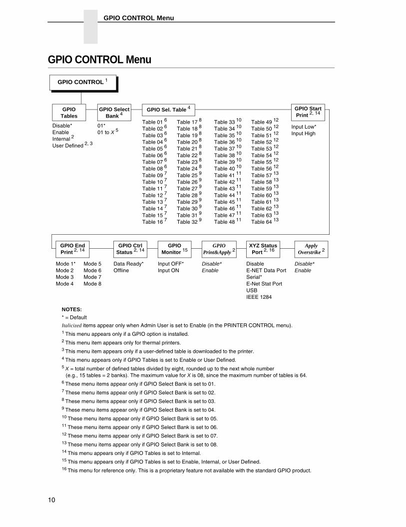
GPIO CONTROL Menu
Table 01 6
Table 02 6
Table 03 6
Table 04 6
Table 05 6
Table 06 6
Table 07 6
Table 08 6
Table 09 7
Table 10 7
Table 11 7
Table 12 7
Table 13 7
Table 14 7
Table 15 7
Table 16 7
Disable* Enable
Internal 2
User Defined 2, 3
GPIO End Print 2, 14
GPIO Ctrl Status 2, 14
GPIO Monitor 15
GPIO Print&Apply 2
XYZ Status Port 2, 16
NOTES:
* = Default
Italicized items appear only when Admin User is set to Enable (in the PRINTER CONTROL menu).1 This menu appears only if a GPIO option is installed.2 This menu item appears only for thermal printers.3 This menu item appears only if a user-defined table is downloaded to the printer.4 This menu appears only if GPIO Tables is set to Enable or User Defined.5 X = total number of defined tables divided by eight, rounded up to the next whole number
(e.g., 15 tables = 2 banks). The maximum value for X is 08, since the maximum number of tables is 64.6 These menu items appear only if GPIO Select Bank is set to 01.7 These menu items appear only if GPIO Select Bank is set to 02.8 These menu items appear only if GPIO Select Bank is set to 03.9 These menu items appear only if GPIO Select Bank is set to 04.10 These menu items appear only if GPIO Select Bank is set to 05.11 These menu items appear only if GPIO Select Bank is set to 06.12 These menu items appear only if GPIO Select Bank is set to 07.13 These menu items appear only if GPIO Select Bank is set to 08.14 This menu appears only if GPIO Tables is set to Internal.15 This menu appears only if GPIO Tables is set to Enable, Internal, or User Defined.16 This menu for reference only. This is a proprietary feature not available with the standard GPIO product.
GPIO CONTROL 1
GPIOTables
GPIO Select Bank 4
01* 01 to X 5
GPIO Sel. Table 4
Table 17 8
Table 18 8
Table 19 8
Table 20 8
Table 21 8
Table 22 8
Table 23 8
Table 24 8
Table 25 9
Table 26 9
Table 27 9
Table 28 9
Table 29 9
Table 30 9
Table 31 9
Table 32 9
Table 33 10
Table 34 10
Table 35 10
Table 36 10
Table 37 10
Table 38 10
Table 39 10
Table 40 10
Table 41 11
Table 42 11
Table 43 11
Table 44 11
Table 45 11
Table 46 11
Table 47 11
Table 48 11
Table 49 12
Table 50 12
Table 51 12
Table 52 12
Table 53 12
Table 54 12
Table 55 12
Table 56 12
Table 57 13
Table 58 13
Table 59 13
Table 60 13
Table 61 13
Table 62 13
Table 63 13
Table 64 13
Input OFF* Input ON
Disable* Enable
Disable E-NET Data Port Serial* E-Net Stat Port USB IEEE 1284
Data Ready* Offline
Mode 5 Mode 6 Mode 7 Mode 8
Mode 1* Mode 2 Mode 3 Mode 4
GPIO Start Print 2, 14
Input Low* Input High
Apply Overstrike 2
Disable* Enable
10

GPIO CONTROL Menu Items
GPIO CONTROL Menu Items
GPIO TablesAllows you to select a mapping table.
• Disable. The default.
• Enable. The user-defined mapping table.
• Internal. The standard internal mapping table.
NOTE: Internal is available only for thermal printers.
• User Defined. The user-defined mapping table.
NOTE: User Defined is available only for thermal printers.
IMPORTANT On SLPA printers, set GPIO Tables to Disable to avoid unexpected tamp motion during printer configuration. After all configurations are complete, set GPIO Tables to Enable.
GPIO Select BankNOTE: This menu appears only if GPIO Tables is set to Enable or User
Defined.
Allows you to select a bank of tables.
The range is from 01 to X, where X is the total number of defined tables (see GPIO Sel. Table below) divided by eight, rounded up to the next whole number (e.g., 15 tables = 2 banks).
The maximum for X is 08, since the maximum number of tables is 64.
GPIO Sel. TableNOTE: This menu appears only if GPIO Tables is set to Enable or User
Defined.
Allows you to select a table.
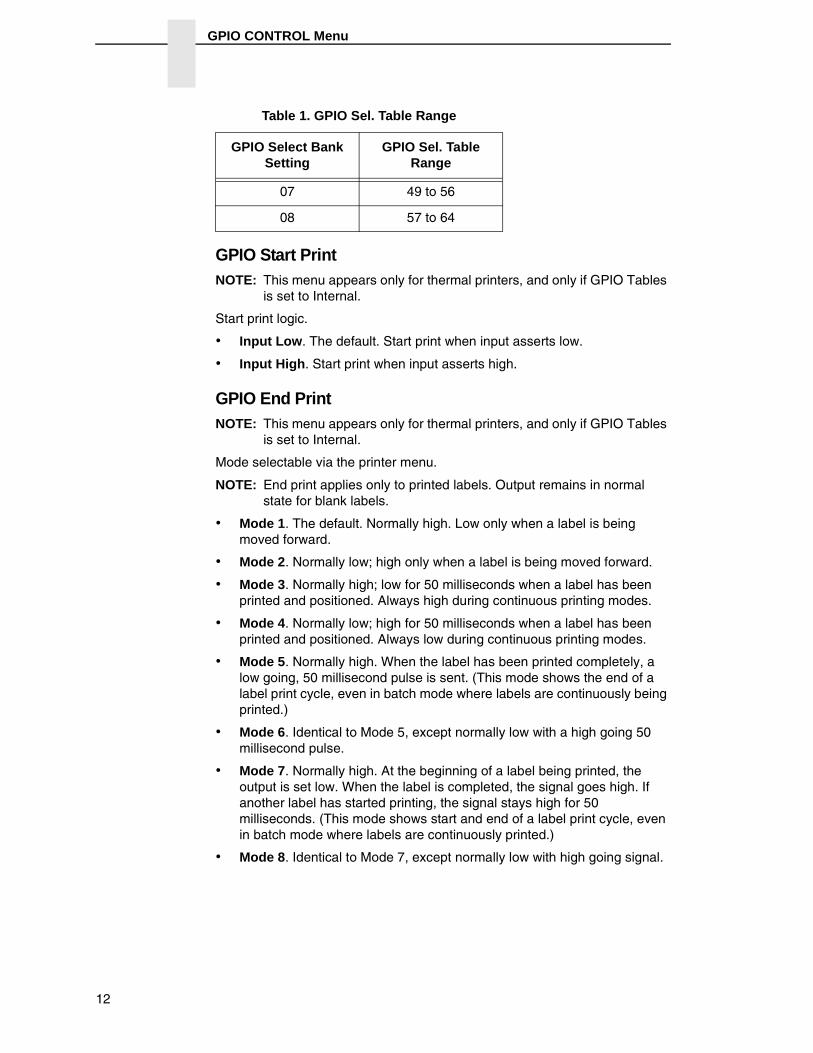
The range depends on the number of defined tables (maximum 64) and the GPIO Select Bank setting. See Table 1.
Table 1. GPIO Sel. Table Range
GPIO Select BankSetting
GPIO Sel. TableRange
01 01 to 08
02 09 to 16
03 17 to 24
04 25 to 32
05 33 to 40
06 41 to 48
11
GPIO CONTROL Menu
GPIO Start PrintNOTE: This menu appears only for thermal printers, and only if GPIO Tables
is set to Internal.
Start print logic.
• Input Low. The default. Start print when input asserts low.
• Input High. Start print when input asserts high.
GPIO End PrintNOTE: This menu appears only for thermal printers, and only if GPIO Tables
is set to Internal.
Mode selectable via the printer menu.
NOTE: End print applies only to printed labels. Output remains in normal state for blank labels.
• Mode 1. The default. Normally high. Low only when a label is being moved forward.
• Mode 2. Normally low; high only when a label is being moved forward.
• Mode 3. Normally high; low for 50 milliseconds when a label has been printed and positioned. Always high during continuous printing modes.
• Mode 4. Normally low; high for 50 milliseconds when a label has been printed and positioned. Always low during continuous printing modes.
• Mode 5. Normally high. When the label has been printed completely, a low going, 50 millisecond pulse is sent. (This mode shows the end of a label print cycle, even in batch mode where labels are continuously being printed.)
• Mode 6. Identical to Mode 5, except normally low with a high going 50 millisecond pulse.
• Mode 7. Normally high. At the beginning of a label being printed, the output is set low. When the label is completed, the signal goes high. If another label has started printing, the signal stays high for 50 milliseconds. (This mode shows start and end of a label print cycle, even in batch mode where labels are continuously printed.)
• Mode 8. Identical to Mode 7, except normally low with high going signal.
07 49 to 56
08 57 to 64
Table 1. GPIO Sel. Table Range
GPIO Select BankSetting
GPIO Sel. TableRange
12
GPIO CONTROL Menu Items
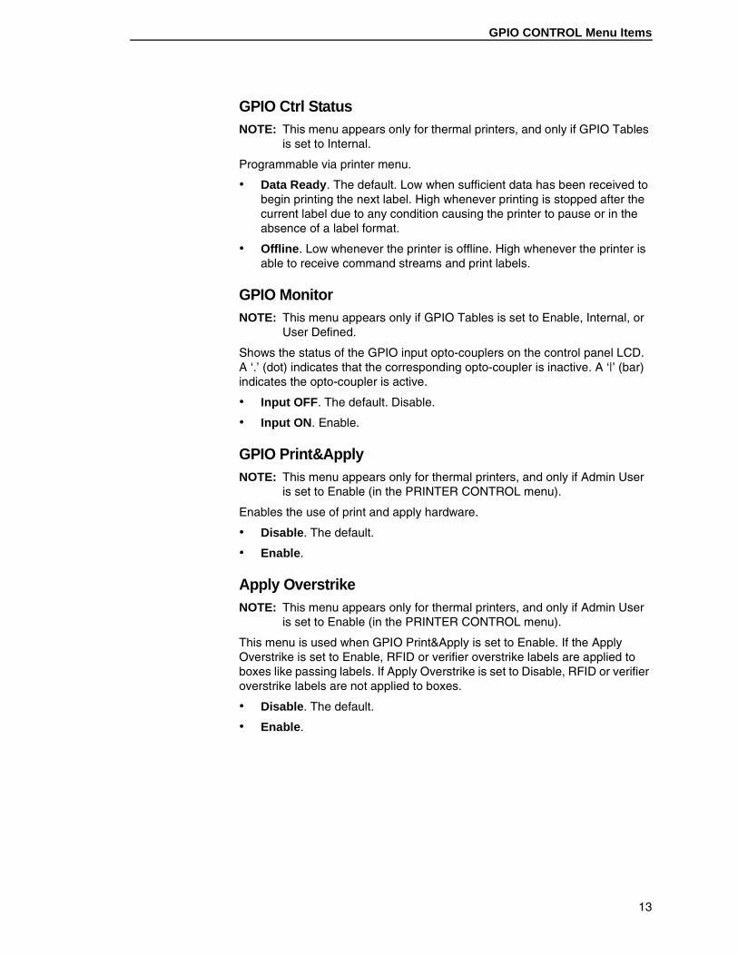
GPIO Ctrl StatusNOTE: This menu appears only for thermal printers, and only if GPIO Tables
is set to Internal.
Programmable via printer menu.
• Data Ready. The default. Low when sufficient data has been received to begin printing the next label. High whenever printing is stopped after the current label due to any condition causing the printer to pause or in the absence of a label format.
• Offline. Low whenever the printer is offline. High whenever the printer is able to receive command streams and print labels.
GPIO MonitorNOTE: This menu appears only if GPIO Tables is set to Enable, Internal, or
User Defined.
Shows the status of the GPIO input opto-couplers on the control panel LCD. A ‘.’ (dot) indicates that the corresponding opto-coupler is inactive. A ‘|’ (bar) indicates the opto-coupler is active.
• Input OFF. The default. Disable.
• Input ON. Enable.
GPIO Print&ApplyNOTE: This menu appears only for thermal printers, and only if Admin User
is set to Enable (in the PRINTER CONTROL menu).
Enables the use of print and apply hardware.
• Disable. The default.
• Enable.
Apply OverstrikeNOTE: This menu appears only for thermal printers, and only if Admin User
is set to Enable (in the PRINTER CONTROL menu).
This menu is used when GPIO Print&Apply is set to Enable. If the Apply Overstrike is set to Enable, RFID or verifier overstrike labels are applied to boxes like passing labels. If Apply Overstrike is set to Disable, RFID or verifier overstrike labels are not applied to boxes.
• Disable. The default.
• Enable.
13
Connector Pinout
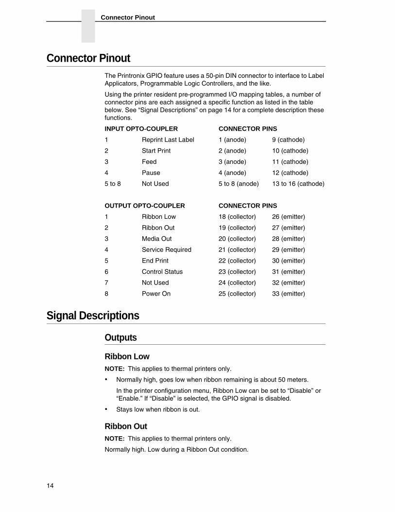
Connector PinoutThe Printronix GPIO feature uses a 50-pin DIN connector to interface to Label Applicators, Programmable Logic Controllers, and the like.
Using the printer resident pre-programmed I/O mapping tables, a number of connector pins are each assigned a specific function as listed in the table below. See “Signal Descriptions” on page 14 for a complete description these functions.
INPUT OPTO-COUPLER CONNECTOR PINS
1 Reprint Last Label 1 (anode) 9 (cathode)
2 Start Print 2 (anode) 10 (cathode)
3 Feed 3 (anode) 11 (cathode)
4 Pause 4 (anode) 12 (cathode)
5 to 8 Not Used 5 to 8 (anode) 13 to 16 (cathode)
OUTPUT OPTO-COUPLER CONNECTOR PINS
1 Ribbon Low 18 (collector) 26 (emitter)
2 Ribbon Out 19 (collector) 27 (emitter)
3 Media Out 20 (collector) 28 (emitter)
4 Service Required 21 (collector) 29 (emitter)
5 End Print 22 (collector) 30 (emitter)
6 Control Status 23 (collector) 31 (emitter)
7 Not Used 24 (collector) 32 (emitter)
8 Power On 25 (collector) 33 (emitter)
Signal Descriptions
Outputs
Ribbon LowNOTE: This applies to thermal printers only.
• Normally high, goes low when ribbon remaining is about 50 meters.
In the printer configuration menu, Ribbon Low can be set to “Disable” or “Enable.” If “Disable” is selected, the GPIO signal is disabled.
• Stays low when ribbon is out.
Ribbon OutNOTE: This applies to thermal printers only.
Normally high. Low during a Ribbon Out condition.
14
Outputs
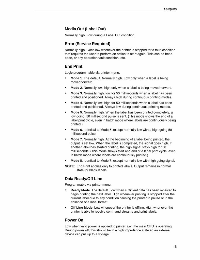
Media Out (Label Out)Normally high. Low during a Label Out condition.
Error (Service Required)Normally high. Goes low whenever the printer is stopped for a fault condition that requires the user to perform an action to start again. This can be head open, or any operation fault condition, etc.
End Print Logic programmable via printer menu.
• Mode 1. The default. Normally high. Low only when a label is being moved forward.
• Mode 2. Normally low; high only when a label is being moved forward.
• Mode 3. Normally high; low for 50 milliseconds when a label has been printed and positioned. Always high during continuous printing modes.
• Mode 4. Normally low; high for 50 milliseconds when a label has been printed and positioned. Always low during continuous printing modes.
• Mode 5. Normally high. When the label has been printed completely, a low going, 50 millisecond pulse is sent. (This mode shows the end of a label print cycle, even in batch mode where labels are continuously being printed.)
• Mode 6. Identical to Mode 5, except normally low with a high going 50 millisecond pulse.
• Mode 7. Normally high. At the beginning of a label being printed, the output is set low. When the label is completed, the signal goes high. If another label has started printing, the high signal stays high for 50 milliseconds. (This mode shows start and end of a label print cycle, even in batch mode where labels are continuously printed.)
• Mode 8. Identical to Mode 7, except normally low with high going signal.
NOTE: End Print applies only to printed labels. Output remains in normal state for blank labels.
Data Ready/Off LineProgrammable via printer menu.
• Ready Mode. The default. Low when sufficient data has been received to begin printing the next label. High whenever printing is stopped after the current label due to any condition causing the printer to pause or in the absence of a label format.
• Off Line Mode. Low whenever the printer is offline. High whenever the printer is able to receive command streams and print labels.
Power OnLow when valid power is applied to printer, i.e., the main CPU is operating. During power off, this should be in a high impedance state so an external device can pull up to a voltage.
15
Signal Descriptions
Inputs
Reprint When low going edge is detected, the printer reprints the last label printed prior to receiving the signal. Only one label is reprinted. The signal must toggle high then low again to reprint another label.
Start Print Signal polarity selectable via printer menu.
• Active Low. The default. When low, the printer will print one label. If still low at the end of the label, another label will be printed without delay. If high, the printer will not print. If the signal goes high while the printer is printing a label, printing will continue until the label has completed. The printer will then stop and obey any other settings for end of label control such as eject, feed a particular distance, etc.
• Active High. Identical to Mode 1 except opposite polarity. A high input will print one label, etc.
Feed• If low, will feed a blank label (or labels) until a high input is detected. A
high input stops the feeding of blank labels, and last blank label fed will stop at top-of-form.
• This signal has the lowest priority over other functions. If the printer is printing, ODV is voiding, or there are any error conditions, the signal is ignored.
NOTE: This signal also has lower priority than Start Print.
Pause• When a signal toggles from high to low, it causes the printer to go into
pause as if the PAUSE key were pressed.
• If a signal goes low during an operation, it will be treated the same way as if the PAUSE key were pressed, i.e., the label will finish if one was being printed, etc.
• This condition can only be reset by pressing the PAUSE key or by a similar command from a host if you have created one.
• The signal must toggle high then low again to achieve another valid pause input.
16
Power and Grounds
Power and Grounds
• +24 VDC
• 24 VDC Return (Ground)
• + 5 VDC
• 5 VDC Return (Ground)
• Frame Ground
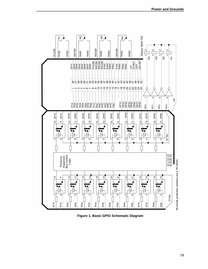
Hardware SpecificationsThis section is a quick reference to the GPIO connections available when using the printer resident pre-programmed I/O mapping tables as well as the electrical specifications of the components used and the voltages available. See page 19 for a schematic diagram.
Pre-Programmed Inputs for Use with Printer MenusStart Print (Polarity programmable via printer menu); input 2
Pause; input 4
Feed; input 3
Reprint (requires 16MB DRAM printer memory to function); input 1
Not used; inputs 5, 6, 7, 8
17
Hardware Specifications
Pre-Programmed Outputs for Use with Printer MenusEnd Print (8 modes via printer menu); output 5
Data Ready/Online (programmable via printer menu); output 6
Ribbon Low; output 1
Ribbon Out; output 2
Error - Service Required; output 4
Media Out; output 3
Power On; output 8
Not used; output 7
External Power Outputs+5VDC (.5 A fused)
+24VDC (.25 A fused) – not available if cutter installed
Two DC ground pins
CompatibilityGPIO is compatible with all T5000r accessories except Coax/Twinax and wireless communication options.
ElectricalInputs (eight total)
• Opto-isolated, separate anode and cathode pins per input
• Input voltage range (steady state); 5-10 VDC
• Series resistor; 4700 ohm, .25W
• Resistor through hole mounted; changeable with common techniques
Outputs (eight total)
• Opto-isolated, NPN transistor, separate collector and emitter pins per output
• Open collector output, NPN transistor
• Current – 300 ma maximum
• 70 VDC collector to emitter voltage maximum.
WARNING For safety reasons voltage should be limited to 42 volts DC max.
• Through hole options for pull-up and series resistors; installable with common techniques
18
Power and Grounds
Figure 1. Basic GPIO Schematic Diagram
7 8 5 6 3 4 1 2 7 8 5 6 3 4 1 2
IP1A
IP1C
IP2A
IP2C
IP3A
IP3C
IP4A
IP4C
IP5A
IP5C
IP6A
IP6C
IP7A
IP7C
IP8A
IP8C
5V R
et
10 9 12 11 14 13 16 15 10 9 12 11 14 13 16 15
Prin
tron
ixE
xpan
sion
Bus
Con
trol
Logi
c
7 8 5 6 3 4 1 2 7 8 5 6 3 4 1 2
OP
1C
OP
1F
OP
2C
OP
2F
OP
3C
OP
3F
OP
4C
OP
4F
OP
5C
OP
5F
OP
6C
OP
6F
OP
7C
OP
7F
OP
8C
OP
8F
10 9 12 11 14 13 16 15 10 9 12 11 14 13 16 15
5V R
et
RY0RY1RY2
RY3
1 2 3 4 5 6 7 8 9 10 11 12 13 14 15 16 17 18 19 20 21 22 23 24 25
26 27 28 29 30 31 32 33 34 35 36 37 38 39 40 41 42 43 44 45 46 47 48 49 50
OP
1FO
P2F
OP
3FO
P4F
OP
5FO
P6F
OP
7FO
P8F
R1C
OM
R2C
OM
R3C
OM
R4C
OM
R1N
CR
2NC
R3N
CR
4NC
R1N
0R
2N0
R3N
0R
4N0
+5V
5V R
ET
+24V
24V
RE
T
IP1A
IP2A
IP3A
IP4A
IP5A
IP6A
IP7A
IP8A
IP1C
IP2C
IP3C
IP4C
IP5C
IP6C
IP7C
IP8C
OP
1CO
P2C
OP
3CO
P4C
OP
5CO
P6C
OP
7CO
P8C
1 3 5 9
RY
0
RY
1
RY
2
RY
3
+5V
1 1 1 1
2 2 2 2
K1
K2
K3
K4
Rel
ays:
NA
I5 T
X2
All
anod
e pr
otec
tion
resi
stor
s ar
e 4.
7K O
hms.
R1C
OM
R1N
C
R1N
O
R2C
OM
R2N
C
R2N
O
R3C
OM
R3N
C
R3N
O
R4C
OM
R4N
C
R4N
O
K1
K2
K3
K4
19

Hardware Specifications
20
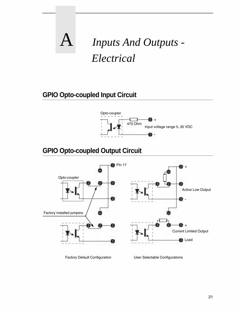
A Inputs And Outputs -
Electrical
GPIO Opto-coupled Input Circuit
GPIO Opto-coupled Output Circuit
Opto-coupler
470 OhmInput voltage range 5..35 VDC
+
-
Opto-coupler
Factory installed jumpers
Active Low Output
Current Limited Output
Factory Default Configuration User Selectable Configurations
+
-
+
Load
Pin 17
21

Appendix A GPIO Opto-coupled Output Circuit
22
B Contact Information
Printronix Customer Support CenterIMPORTANT Please have the following information available prior to calling the
Printronix Customer Support Center:
• Model number
• Serial number (located on the back of the printer)
• Installed options (i.e., interface and host type if applicable to the problem)
• Configuration printout:
Thermal Printer See “Printing A Configuration” in the Quick Setup Guide
Line Matrix Printer Press PRT CONFIG on the control panel, then press Enter
• Is the problem with a new install or an existing printer?
• Description of the problem (be specific)
• Good and bad samples that clearly show the problem (faxing or emailing of these samples may be required)
Americas (714) 368-2686
Europe, Middle East, and Africa (31) 24 6489 311
Asia Pacific (65) 6548 4114
China (86) 800-999-6836
http://www.printronix.com/support.aspx
23
Appendix B Printronix Supplies Department
Printronix Supplies DepartmentContact the Printronix Supplies Department for genuine Printronix supplies.
Americas (800) 733-1900
Europe, Middle East, and Africa 33 (0) 1 46 25 19 07
Asia Pacific (65) 6548 4116 or (65) 6548 4182
China (86) 400-886-5598
India (800) 102-7869
http://www.printronix.com/supplies-parts.aspx
Corporate OfficesPrintronix, Inc. 15345 Barranca Parkway Irvine, CA 92618 U.S.A. Phone: (714) 368-2300 Fax: (714) 368-2600
Printronix Inc. c/o Printronix Nederland BV Bijsterhuizen 11-38 6546 AS Nijmegen The Netherlands Phone: (31) 24 6489489 Fax: (31) 24 6489499
Printronix Schweiz GmbH 42 Changi South Street 1 Changi South Industrial Estate Singapore 486763 Phone: (65) 6542 0110 Fax: (65) 6546 1588
Printronix Commercial (Shanghai) Co. Ltd 22F, Eton Building East, No.555, Pudong Av., Shanghai City, 200120, P R China Phone: (86) 400 886 5598 Fax: (86-21) 5138 0564
Visit the Printronix web site at www.printronix.com
24


176792-001J
*176792-001*