Embed Size (px)
Citation preview
FUJITSU SEMICONDUCTORCONTROLLER MANUAL
FR-V FAMILYSOFTUNETM WORKBENCH
USER'S MANUALfor V6
CM71-00333-2E

FUJITSU LIMITED
FR-V FAMILYSOFTUNETM Workbench
USER'S MANUALfor V6

PREFACE
■ What is the SOFTUNE Workbench ?SOFTUNE Workbench is support software for developing programs for the FR-V families of
microprocessors.
It is a combination of a development manager, simulator debugger, emulator debugger, monitor debugger,
and an integrated development environment for efficient development.
■ Purpose of this manual and target readersThis manual explains the functions of SOFTUNE Workbench. This manual is intended for engineers developing
various types of products using SOFTUNE Workbench. Be sure to read this manual completely.
■ TrademarksSOFTUNE is a trademark of FUJITSU Ltd.
FR-V is a product of FUJITSU Ltd.
Microsoft, Windows are registered trademarks of Microsoft Corporation in the USA and/or other countries.
■ Organization of ManualThis manual consists of two chapters.
Chapter 1 Standard Functions
This chapter describes the standard functions on the SOFTUNE Workbench.
Chapter 2 Dependence Functions
This chapter describes the functions depending on the each debugger.
Chapter 3 Multi-core Development Environment
In this chapter, function for development environment for multi-core is explained.
i
Copyright ©2003-2006 FUJITSU LIMITED All rights reserved
• The contents of this document are subject to change without notice. Customers are advised to consult with FUJITSU sales representatives before ordering.
• The information, such as descriptions of function and application circuit examples, in this document are presented solelyfor the purpose of reference to show examples of operations and uses of FUJITSU semiconductor device; FUJITSU doesnot warrant proper operation of the device with respect to use based on such information. When you develop equipmentincorporating the device based on such information, you must assume any responsibility arising out of such use of theinformation. FUJITSU assumes no liability for any damages whatsoever arising out of the use of the information.
• Any information in this document, including descriptions of function and schematic diagrams, shall not be construed aslicense of the use or exercise of any intellectual property right, such as patent right or copyright, or any other right ofFUJITSU or any third party or does FUJITSU warrant non-infringement of any third-party's intellectual property right orother right by using such information. FUJITSU assumes no liability for any infringement of the intellectual property rightsor other rights of third parties which would result from the use of information contained herein.
• The products described in this document are designed, developed and manufactured as contemplated for general use,including without limitation, ordinary industrial use, general office use, personal use, and household use, but are notdesigned, developed and manufactured as contemplated (1) for use accompanying fatal risks or dangers that, unlessextremely high safety is secured, could have a serious effect to the public, and could lead directly to death, personal injury,severe physical damage or other loss (i.e., nuclear reaction control in nuclear facility, aircraft flight control, air trafficcontrol, mass transport control, medical life support system, missile launch control in weapon system), or (2) for userequiring extremely high reliability (i.e., submersible repeater and artificial satellite).Please note that FUJITSU will not be liable against you and/or any third party for any claims or damages arising inconnection with above-mentioned uses of the products.
• Any semiconductor devices have an inherent chance of failure. You must protect against injury, damage or loss from suchfailures by incorporating safety design measures into your facility and equipment such as redundancy, fire protection, andprevention of over-current levels and other abnormal operating conditions.
• If any products described in this document represent goods or technologies subject to certain restrictions on export underthe Foreign Exchange and Foreign Trade Law of Japan, the prior authorization by Japanese government will be required forexport of those products from Japan.
ii
Reading This Manual
■ Product NamesIn this manual, product names are abbreviated as follows:
The Microsoft® Windows® 98 operating system is abbreviated to Windows 98.
The Microsoft® Windows® Millennium Edition operating system is abbreviated to Windows Me.
The Microsoft® Windows® NT® Workstation operating system Version 4.0 and the Microsoft® Windows®
NT® Server network operating system Version 4.0 are abbreviated to Windows NT 4.0.
Microsoft® Windows® 2000 Professional operating system,
Microsoft® Windows® 2000 Server operating system,
Microsoft® Windows® 2000 Advanced Server operating system,
Microsoft® Windows® 2000 Datacenter Server operating system are abbreviated to Windows 2000.
iii

iv
CONTENTS
CHAPTER 1 STANDARD FUNCTIONS ............................................................................ 11.1 Workspace Management Function ..................................................................................................... 21.2 Project Management Function ............................................................................................................ 31.3 Project Dependence ........................................................................................................................... 41.4 Make/Build Function ........................................................................................................................... 5
1.4.1 Customize Build Function .............................................................................................................. 61.5 Include Dependencies Analysis Function ........................................................................................... 81.6 Functions of Setting Tool Options ....................................................................................................... 91.7 Error Jump Function ......................................................................................................................... 101.8 Editor Functions ................................................................................................................................ 121.9 Storing External Editors .................................................................................................................... 131.10 Storing External Tools ...................................................................................................................... 151.11 Macro Descriptions Usable in Manager ............................................................................................ 161.12 Setting Operating Environment ......................................................................................................... 201.13 Debugger Types ............................................................................................................................... 211.14 Memory Operation Functions ........................................................................................................... 221.15 Register Operations .......................................................................................................................... 231.16 Line Assembly and Disassembly ...................................................................................................... 241.17 Symbolic Debugging ......................................................................................................................... 25
1.17.1 Referring to Local Symbols ......................................................................................................... 271.17.2 Referring to C/C++ Variables ...................................................................................................... 28
1.18 I/O Operations .................................................................................................................................. 30
CHAPTER 2 DEPENDENCE FUNCTIONS ..................................................................... 312.1 Simulator Debugger .......................................................................................................................... 32
2.1.1 Instruction Simulation .................................................................................................................. 332.1.2 Memory Simulation ...................................................................................................................... 342.1.3 I/O Port Simulation ...................................................................................................................... 352.1.4 Interrupt Simulation ..................................................................................................................... 362.1.5 Reset Simulation ......................................................................................................................... 382.1.6 Low-Power Consumption Mode Simulation ................................................................................. 39
2.2 Emulator Debugger ........................................................................................................................... 402.2.1 Notes on Executing Program ....................................................................................................... 412.2.2 Cache Control .............................................................................................................................. 422.2.3 MMU Setting ................................................................................................................................ 442.2.4 Command Execution while Executing Program .......................................................................... 45
2.3 Monitor Debugger ............................................................................................................................. 462.3.1 Resources Used by Monitor Program ......................................................................................... 472.3.2 Cache Control .............................................................................................................................. 482.3.3 MMU Setting ................................................................................................................................ 502.3.4 Notes on Executing Program ....................................................................................................... 51
2.4 Abortion of Program Execution (SIM, EML, MON) ........................................................................... 522.4.1 Software Breaks (EML, MON) ..................................................................................................... 53
v
2.4.2 Hardware Breaks (EML, MON) .................................................................................................... 542.4.3 External Trigger Break (EML) ...................................................................................................... 552.4.4 Break Points (SIM) ...................................................................................................................... 562.4.5 Data Break Points (SIM, EML, MON) .......................................................................................... 572.4.6 Guarded Access Breaks (SIM) .................................................................................................... 592.4.7 Forced Break (SIM, EML) ............................................................................................................ 602.4.8 Breaks by Issue Restrictions (SIM) ............................................................................................. 612.4.9 Breaks by Conflicting Writing (SIM) ............................................................................................. 622.4.10 Breaks Caused by Detection of the CPU Stopped State (EML) .................................................. 63
2.5 Analyzing Program Execution (SIM, EML, MON) ............................................................................. 642.5.1 Trace (SIM, EML) ........................................................................................................................ 652.5.2 Trace Data (SIM, EML) ................................................................................................................ 662.5.3 Tracing Function (SIM, EML) ....................................................................................................... 672.5.4 Setting Trace (SIM, EML) ............................................................................................................ 682.5.5 Displaying Trace Data (SIM, EML) .............................................................................................. 692.5.6 Display Format of Trace Data (SIM, EML) .................................................................................. 702.5.7 Searching Trace Data (SIM, EML) .............................................................................................. 712.5.8 Saving Trace Data (SIM, EML) .................................................................................................... 722.5.9 Clearing Trace Data (SIM, EML) ................................................................................................. 732.5.10 Notes on Use of Tracing Function (SIM, EML) ............................................................................ 742.5.11 Measuring Execution Cycle Counts (EML) .................................................................................. 752.5.12 Measuring Execution Time (SIM) ................................................................................................ 762.5.13 Measuring Execution Time (MON) .............................................................................................. 772.5.14 Performance Measurement (EML) .............................................................................................. 78
2.5.14.1 Performance Measurement Procedure .................................................................................... 79
CHAPTER 3 MULTI-CORE DEVELOPMENT ENVIRONMENT ..................................... 813.1 Development Environment for Multi-core ......................................................................................... 823.2 Object Programming Model .............................................................................................................. 833.3 Target File ......................................................................................................................................... 84
3.3.1 Target File at Multi-core Environment ......................................................................................... 853.3.2 Composition of a Target File ....................................................................................................... 86
3.4 Multi-core Project .............................................................................................................................. 873.4.1 Master Project/Slave Project ....................................................................................................... 943.4.2 Master/Slave Projects and Composition of Project ..................................................................... 953.4.3 Sub Project of Master/Slave Projects .......................................................................................... 963.4.4 Shared Project ............................................................................................................................. 973.4.5 Setup of Master Project ............................................................................................................. 1003.4.6 Set up of Slave Project .............................................................................................................. 1013.4.7 Set Up of ABS Concatenation Tool ........................................................................................... 1023.4.8 Allocation/Concatenation Sections at Multi-core ....................................................................... 1033.4.9 Make and Build .......................................................................................................................... 1043.4.10 Customize build ......................................................................................................................... 1053.4.11 Master-Slave Project and Macro Name ..................................................................................... 106
3.5 Session ........................................................................................................................................... 1073.5.1 What is Current Session? .......................................................................................................... 1083.5.2 Debugging Session and Analysis Session ................................................................................ 109
vi
3.6 Debugging Multi-core ...................................................................................................................... 1103.6.1 Startup of Debugger .................................................................................................................. 1113.6.2 Connect Sessions ...................................................................................................................... 1153.6.3 Menu or Toolbar ........................................................................................................................ 1163.6.4 Debugging Window ................................................................................................................... 1173.6.5 Loading Program ....................................................................................................................... 1193.6.6 ABS Tab in Project Window ...................................................................................................... 1213.6.7 Break ......................................................................................................................................... 1223.6.8 Synchronous Execution and Synchronous Break ..................................................................... 1233.6.9 Analysis Feature ........................................................................................................................ 124
3.7 Duplication of Workbench ............................................................................................................... 1253.7.1 Start Duplicating ........................................................................................................................ 1263.7.2 Termination of Duplicated Workbench ...................................................................................... 1283.7.3 Creating and Loading Target File .............................................................................................. 129
3.8 Command ....................................................................................................................................... 1303.8.1 Command .................................................................................................................................. 1313.8.2 Intrinsic Function ....................................................................................................................... 133
3.9 Cautions for Multi-core Debugging ................................................................................................. 134
vii

viii
CHAPTER 1STANDARD FUNCTIONS
This chapter describes the standard functions on the SOFTUNE Workbench.
1.1 Workspace Management Function
1.2 Project Management Function
1.3 Project Dependence
1.4 Make/Build Function
1.5 Include Dependencies Analysis Function
1.6 Functions of Setting Tool Options
1.7 Error Jump Function
1.8 Editor Functions
1.9 Storing External Editors
1.10 Storing External Tools
1.11 Macro Descriptions Usable in Manager
1.12 Setting Operating Environment
1.13 Debugger Types
1.14 Memory Operation Functions
1.15 Register Operations
1.16 Line Assembly and Disassembly
1.17 Symbolic Debugging
1.18 I/O Operations
1
CHAPTER 1 STANDARD FUNCTIONS
1.1 Workspace Management Function
This section explains the workspace management function of SOFTUNE Workbench.
■ Workspace SOFTUNE Workbench uses workspace as a container to manage two or more projects including
subprojects.
For example, a project that creates a library and a project that creates a target file using the project can be
stored in one workspace.
■ Workspace Management Function To manage two or more projects, workspace manages the following information:
• Project
• Active project
• Subproject
■ Project The operation performed in SOFTUNE Workbench is based on the project. The project is a set of files and
procedures necessary for creation of a target file. The project file contains all data managed by the project.
■ Active Project The active project is basic to workspace and undergoes [Make], [Build], [Compile/Assemble], [Start
Debug], and [Update Dependence] in the menu. [Make], [Build], [Compile/Assemble], and [Update
Dependence] affect the subprojects within the active project.
If workspace contains some project, it always has one active project.
■ Subproject The subproject is a project on which other projects depend. The target file in the subproject is linked with
the parent project of the subproject in creating a target file in the parent project.
This dependence consists of sharing target files output by the subproject, so a subproject is first made and
built. If making and building of the subproject is unsuccessful, the parent project of the subproject will not
be made and built.
The target file in the subproject is however not linked with the parent project when:
• An absolute (ABS)-type project is specified as a subproject.
• A library (LIB)-type project is specified as a subproject.
■ Restrictions on Storage of Two or More Projects Only one REALOS-type project can be stored in one workspace.
2
CHAPTER 1 STANDARD FUNCTIONS
1.2 Project Management Function
This section explains the project management function of SOFTUNE Workbench.
■ Project Management Function The project manages all information necessary for development of a microcontroller system. Especially, its
major purpose is to manage information necessary for creation of a target file.
The project manages the following information:
• Project configuration
• Active project configuration
• Information on source files, include files, other source files, library files
• Information on tools executed before and after executing language tools (customize build function)
■ Project Configuration The project configuration is a series of settings for specifying the characteristics of a target file, and
making, building, compiling and assembling is performed in project configurations.
Two or more project configurations can be created in a project. The default project configuration name is
Debug. A new project configuration is created on the setting of the selected existing project configuration.
In the new project configuration, the same files as those in the original project configuration are always
used.
By using the project configuration, the settings of programs of different versions, such as the optimization
level of a compiler and MCU setting, can be created within one project.
In the project configuration, the following information is managed:
• Name and directory of target file
• Information on options of language tools to create target file by compiling, assembling and linkingsource files
• Information on whether to build file or not
• Information on setting of debugger to debug target file
■ Active Project Configuration The active project configuration at default undergoes [Make], [Build], [Compile/Assemble], [Start Debug],
and [Update Dependence].
The setting of the active project configuration is used for the file state displayed in the SRC tab of project
window and includes files detected in the Dependencies folder.
3
CHAPTER 1 STANDARD FUNCTIONS
1.3 Project Dependence
This section explains the project dependence of SOFTUNE Workbench.
■ Project Dependence If target files output by other projects must be linked, a subproject is defined in the project required in
[Project Dependence] in the [Project] menu. The subproject is a project on which other projects depend.
By defining project dependence, a subproject can be made and built to link its target file before making and
building the parent project.
The use of project dependence enables simultaneous making and building of two or more projects
developed in one workspace.
A project configuration in making and building a subproject in [Project Configuration]-[Build
Configuration] in the [Project] menu can be specified.
4
CHAPTER 1 STANDARD FUNCTIONS
1.4 Make/Build Function
This section explains the project dependence of SOFTUNE Workbench.
■ Make Function Make function generates a target file by compiling/assembling only updated source files from all source
files registered in a project, and then joining all required object files.
This function allows compiling/assembling only the minimum of required files. The time required for
generating a target file can be sharply reduced, especially, when debugging.
For this function to work fully, the dependence between source files and include files should be accurately
grasped. To do this, SOFTUNE Workbench has a function for analyzing include dependence. To perform
this function, it is necessary to understand the dependence of a source file and include file. SOFTUNE
Workbench has the function of analyzing the include file dependence. For details, see Section "1.5 Include
Dependencies Analysis Function".
■ Build Function Build function generates a target file by compiling/assembling all source files registered with a project,
regardless of whether they have been updated or not, and then by joining all required object files. Using
this function causes all files to be compiled/assembled, resulting in the time required for generating the
target file longer. Although the correct target file can be generated from the current source files.
The execution of Build function is recommended after completing debugging at the final stage of program
development.
Note:
When executing the Make function using a source file restored from backup, the integrity between anobject file and a source file may be lost. If this happens, executing the Build function again.
5
CHAPTER 1 STANDARD FUNCTIONS
1.4.1 Customize Build Function
This section describes the SOFTUNE Workbench function to set the Customize Build function.
■ Customize Build Function In SOFTUNE Workbench, different tools can be operated automatically before and after executing the
Assembler, Compiler, Linker, Librarian, Converter, or Configurator started at Compile, Assemble, Make,
or Build.
The following operations can be performed automatically during Make or Build using this function:
• Starting the syntax check before executing the Compiler,
• After executing the Converter, starting the S-format binary Converter (m2bs.exe) and convertingMotorola S-format files to binary format files.
■ Options An option follows the tool name to start a tool from SOFTUNE Workbench. The options include any file
name and tool-specific options. SOFTUNE Workbench has the macros indicating that any file name and
tool-specific options are specified as options.
If any character string other than parameters is specified, it is passed directly to the tool. For details about
the parameters, see Section "1.11 Macro Descriptions Usable in Manager".
■ Precautions When checking [Use the Output window], note the following:
• Once a tool is activated, Make/Build suspends until the tool is terminated.
• The Output window must not be used with a tool using a wait state for user input while the tool isexecuting. The user can not perform input while the Output window is in use, so the tool cannot beterminated.
To forcibly terminate the tool, select the tool on the Task bar and input Control - C, or Control - Z.
6
CHAPTER 1 STANDARD FUNCTIONS
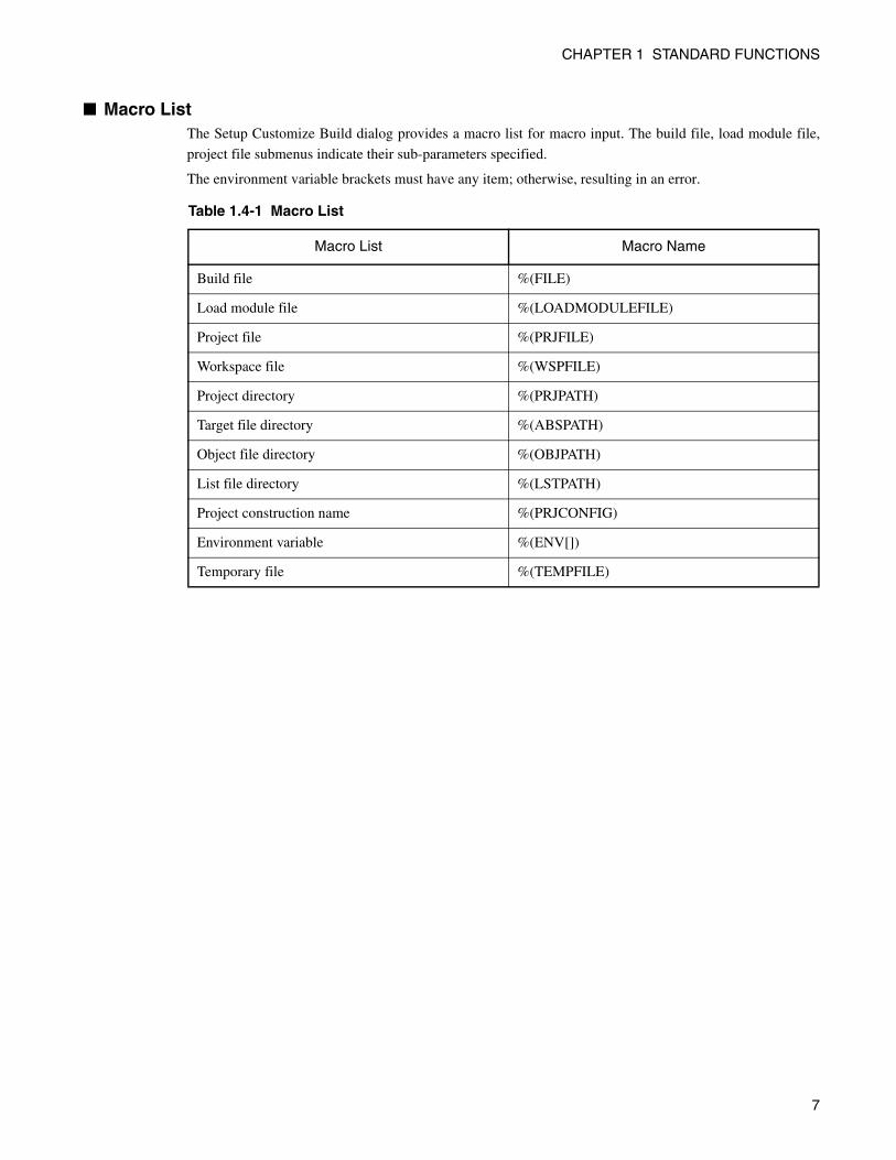
■ Macro List The Setup Customize Build dialog provides a macro list for macro input. The build file, load module file,
project file submenus indicate their sub-parameters specified.
The environment variable brackets must have any item; otherwise, resulting in an error.
Table 1.4-1 Macro List
Macro List Macro Name
Build file %(FILE)
Load module file %(LOADMODULEFILE)
Project file %(PRJFILE)
Workspace file %(WSPFILE)
Project directory %(PRJPATH)
Target file directory %(ABSPATH)
Object file directory %(OBJPATH)
List file directory %(LSTPATH)
Project construction name %(PRJCONFIG)
Environment variable %(ENV[])
Temporary file %(TEMPFILE)
7
CHAPTER 1 STANDARD FUNCTIONS
1.5 Include Dependencies Analysis Function
This section describes the function of the Include Dependencies Analysis.
■ Analyzing Include Dependencies A source file usually includes some include files. When only an include file has been modified leaving a
source file unchanged, SOFTUNE Workbench cannot execute the Make function unless it has accurate and
updated information about which source file includes which include files.
For this reason, SOFTUNE Workbench has a built-in Include Dependencies Analysis function. This
function can be activated by selecting the [Project] -[Include Dependencies] command. By using this
function, uses can know the exact dependencies, even if an include file includes another include file.
SOFTUNE Workbench automatically updates the dependencies of the compiled/assembled files.
Note:
When executing the [Project] - [Include Dependencies] command, the Output window is redrawn andreplaced by the dependencies analysis result.
If the contents of the current screen are important (error message, etc.), save the contents to a fileand then execute the Include Dependencies command.
8
CHAPTER 1 STANDARD FUNCTIONS
1.6 Functions of Setting Tool Options
This section describes the functions to set options for the language tools activated from SOFTUNE Workbench.
■ Function of Setting Tool Options To create a desired target file, it is necessary to specify options for the language tools such as a compiler,
assembler, and linker. SOFTUNE Workbench stores and manages the options specified for each tool in
project configurations.
Tool options include the options effective for all source files (common options) and the options effective
for specific source files (individual options). For details about the option setting, refer to Section 4.5.5,
SOFTUNE Workbench Operation Manual.
• Common options
These options are effective for all source files (excluding those for which individual options arespecified) stored in the project.
• Individual options
These options are compile/assemble options effective for specific source files. The common optionsspecified for source files for which individual options are specified become invalid.
■ Tool Options In SOFTUNE Workbench, the macros indicating that any file name and directory name are specified as
options.
If any character string other than parameters is specified, it is passed directly to the tool. For details about
the tool options for each tool, see Section "1.11 Macro Descriptions Usable in Manager".
■ Reference Section Setup Project
Development Environment
9
CHAPTER 1 STANDARD FUNCTIONS
1.7 Error Jump Function
This section describes the error jump function in SOFTUNE Workbench.
■ Error Jump Function When an error, such as a compile error occurs, double-clicking the error message in the Output window
opens the source file where the error occurred and automatically moves the cursor to the error line. This
function permits efficient removal of compile errors, etc.
The SOFTUNE Workbench Error Jump function analyzes the source file names and line number
information embedded in the error message displayed in the Output window, opens the matching file, and
jumps automatically to the line.
The location where a source file name and line number information are embedded in an error message,
varies with the tool outputting the error.
An error message format can be added to an existing one or modified into a new one. However, the modify
error message formats for pre-installed Fujitsu language tools are defined as part of the system, these can
not be modified.
A new error message format should be added when working the Error Jump function with user registed. To
set Error Jump, execute the [Setup] - [Error] command.
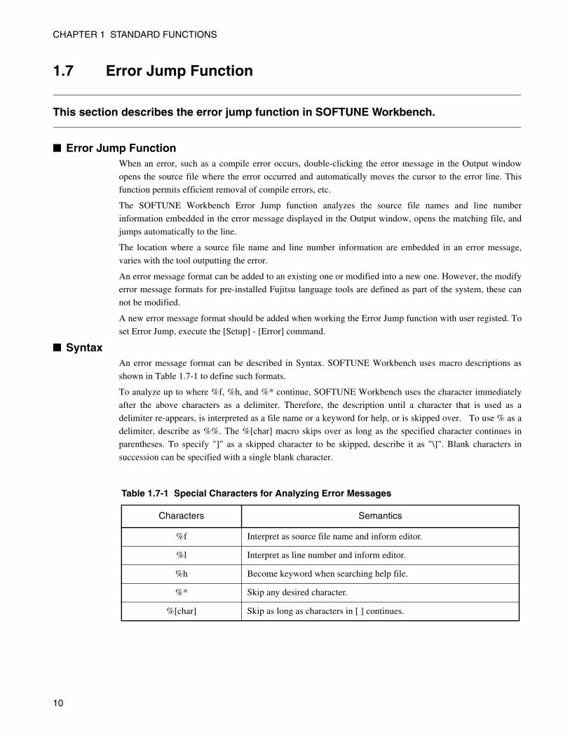
■ Syntax An error message format can be described in Syntax. SOFTUNE Workbench uses macro descriptions as
shown in Table 1.7-1 to define such formats.
To analyze up to where %f, %h, and %* continue, SOFTUNE Workbench uses the character immediately
after the above characters as a delimiter. Therefore, the description until a character that is used as a
delimiter re-appears, is interpreted as a file name or a keyword for help, or is skipped over. To use % as a
delimiter, describe as %%. The %[char] macro skips over as long as the specified character continues in
parentheses. To specify "]" as a skipped character to be skipped, describe it as "\]". Blank characters in
succession can be specified with a single blank character.
Table 1.7-1 Special Characters for Analyzing Error Messages
Characters Semantics
%f Interpret as source file name and inform editor.
%l Interpret as line number and inform editor.
%h Become keyword when searching help file.
%* Skip any desired character.
%[char] Skip as long as characters in [ ] continues.
10
CHAPTER 1 STANDARD FUNCTIONS
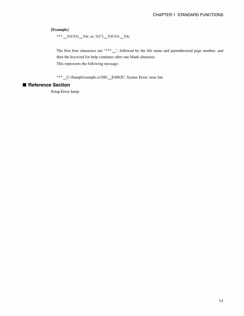
[Example]
*** %f(%l) %h: or, %[*] %f(%l) %h:
The first four characters are "*** ", followed by the file name and parenthesized page number, and
then the keyword for help continues after one blank character.
This represents the following message:
*** C:\Sample\sample.c(100) E4062C: Syntax Error: near /int.
■ Reference Section Setup Error Jump
] ] ] ]
]
] ]
11
CHAPTER 1 STANDARD FUNCTIONS
1.8 Editor Functions
This section describes the functions of the SOFTUNE Workbench built-in standard editor.
■ Standard Editor SOFTUNE Workbench has a built-in editor called the standard editor. The standard editor is activated as
the Edit window in SOFTUNE Workbench. As many Edit windows as are required can be opened at one
time.
The standard editor has the following functions in addition to regular editing functions.
• Keyword marking function in C/C++/assembler source file
Displays reserved words, such as if and for, in different color
• Error line marking function
The error line can be viewed in a different color, when executing Error Jump.
• Tag setup function
A tag can be set on any line, and instantaneously jumps to the line. Once a tag is set, the line isdisplayed in a different color.
• Ruler, line number display function
The Ruler is a measure to find the position on a line; it is displayed at the top of the Edit window. A linenumber is displayed at the left side of the Edit window.
• Automatic indent function
When a line is inserted using the Enter key, the same indent as the preceding line is set automatically atthe inserted line. If the space or tab key is used on the preceding line, the same use is set at the insertedline as well.
• Function to display, Line Feed code, and Tab code
When a file includes a Line Feed code, and Tab code, these codes are displayed with special symbols.
• Undo function
This function cancels the preceding editing action to restore the previous state. When more than onecharacter or line is edited, the whole portion is restored.
• Tab size setup function
Tab stops can be specified by defining how many digits to skip when Tab codes are inserted. Thedefault is 8.
• Font changing function
The font size for characters displayed in the Edit window can be selected.
■ Reference Section Edit Window (The Standard Editor)
12

CHAPTER 1 STANDARD FUNCTIONS
1.9 Storing External Editors
This section describes the function to set an external editor in SOFTUNE Workbench.
■ External Editor SOFTUNE Workbench has a built-in standard editor, and use of this standard editor is recommended.
However, another accustomed editor can be used, with setting it, instead of an edit. There is no particular
limit on which editor can be set, but some precautions (below) may be necessary. Use the [Setup] - [Editor]
command to set an external editor.
■ Precautions • Error jump function
The Error Jump cannot move the cursor to an error line if the external editor does not have a function tospecify the cursor location when activated.
• File save at compiling/assembling
SOFTUNE Workbench cannot control an external editor. Always save the file you are editing beforecompiling/assembling.
■ Setting Options When activating an external editor from SOFTUNE Workbench, options must be added immediately after
the editor name. The names of file to be opened by the editor and the initial location of the cursor (the line
number) can be specified. SOFTUNE Workbench has a set of special parameters for specifying any file
name and line number, as shown in Table 1.9-1. If any other character are described by these parameters,
such character are passed as is to the editor.
%f (File name) is determined as follows:
1. If the focus is on the SRC tab of project window, and if a valid file name is selected, the selected file
name becomes the file name.
2. When a valid file name cannot be acquired by the above procedure, the file name with a focus in the
built-in editor becomes the file name.
Also filenames cannot be given double-quotes in the expansion of %f macros.
%x (project path) is determined as follows:
1. If a focus is on the SRC tab of project window and a valid file name is selected, the project path is a
path to the project in which the file is stored.
2. If no path is obtained, the project path is a path to the active project.
Therefore, it is necessary for you to provide double-quotes for %f. Depending on the editor, there are line
numbers to which there will be no correct jump if the entire option is not given double-quotes.
13
CHAPTER 1 STANDARD FUNCTIONS
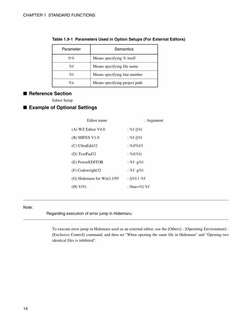
■ Reference Section Editor Setup
■ Example of Optional Settings
Note:
Regarding execution of error jump in Hidemaru:
To execute error jump in Hidemaru used as an external editor, use the [Others] - [Operating Environment] -
[Exclusive Control] command, and then set "When opening the same file in Hidemaru" and "Opening two
identical files is inhibited".
Table 1.9-1 Parameters Used in Option Setups (For External Editors)
Parameter Semantics
%% Means specifying % itself
%f Means specifying file name
%l Means specifying line number
%x Means specifying project path
Editor name : Argument
(A) WZ Editor V4.0 : %f /j%l
(B) MIFES V1.0 : %f /j%l
(C) UltraEdit32 : %f/%l/1
(D) TextPad32 : %f(%l)
(E) PowerEDITOR : %f -g%l
(F) Codewright32 : %f -g%l
(G) Hidemaru for Win3.1/95 : /j%l:1 %f
(H) ViVi : /line=%l %f
14
CHAPTER 1 STANDARD FUNCTIONS
1.10 Storing External Tools
This section describes the SOFTUNE Workbench function to set an external tool.
■ External Tools A non-standard tool not attached to SOFTUNE Workbench can be used by setting it as an external tool and
by calling it from SOFTUNE Workbench. Use this function to coordinate with a source file version control
tool.
If a tool set as an external tool is designed to output the execution result to the standard output and the
standard error output through the console application, the result can be specified to the SOFTUNE
Workbench Output window. In addition, the allow description of additional parameters each time the tool is
activated.
To set an external tool, use the [Setup] - [Tool] command.
To select the title of a set tool, use the [Setup] - [Activating Tool] command.
■ Setting Options When activating an external tool from SOFTUNE Workbench, options must be added immediately after the
tool name. Specify the file names, and unique options, etc.
SOFTUNE Workbench has a set of special parameters for specifying any file name and unique tool
options.
If any characters described other than these parameters, such characters are passed as is to the external tool.
For details about the parameters, see Section "1.11 Macro Descriptions Usable in Manager".
■ Precautions When checking [Use the Output window], note the following:
• Once a tool is activated, neither other tools nor the compiler/assembler can be activated until the tool isterminated.
• The Output window must not be used with a tool using a wait state for user input while the tool isexecuting. The user can not perform input while the Output window is in use, so the tool cannot beterminated.
To forcibly terminate the tool, select the tool on the Task bar and input Control - C, or Control - Z.
■ Reference Section Setting Tools
Start an External Tool
15
CHAPTER 1 STANDARD FUNCTIONS
1.11 Macro Descriptions Usable in Manager
This section explains the macro descriptions that can be used in the manager of SOFTUNE Workbench.
■ Macros SOFTUNE Workbench has special parameters indicating that any file name and tool-specific options are
specified as options.
The use of these parameters as tool options eliminates the need for options specified each time each tool is
started.
The type of macro that can be specified and macro expansion slightly vary depending on where to describe
macros. The macros usable for each function are detailed below. For the macros that can be specified for
"Error Jump" and "External Editors" see Sections "1.7 Error Jump Function" and "1.9 Storing External
Editors".
■ Macro List The following is a list of macros that can be specified in SOFTUNE Workbench.
The macros usable for each function are listed below.
• External tools: Table 1.11-1 and Table 1.11-2
• Customize build: Table 1.11-1 and Table 1.11-2
• Tool options: Table 1.11-2
The directory symbol \ is added to the option directories in Table 1.11-1 but not to the macro directories in
Table 1.11-2.
The sub-parameters in Table 1.11-3 can be specified in %(FILE),
%(LOADMOUDLEFILE), %(PRJFILE), and %(WSPFILE).
The sub-parameter is specified in the form of %(PRJFILE[PATH]).
If the current directory is on the same drive, the relative path is used. The current directory is the workspace
directory for %(PRJFILE), and %(WSPFILE), and the project directory for other than these.
16
CHAPTER 1 STANDARD FUNCTIONS
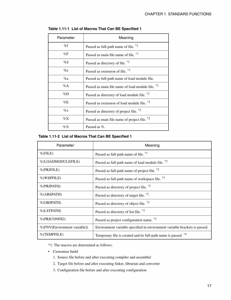
*1: The macros are determined as follows:
• Customize build
1. Source file before and after executing compiler and assembler
2. Target file before and after executing linker, librarian and converter
3. Configuration file before and after executing configuration
Table 1.11-1 List of Macros That Can BE Specified 1
Parameter Meaning
%f Passed as full-path name of file. *1
%F Passed as main file name of file. *1
%d Passed as directory of file. *1
%e Passed as extension of file. *1
%a Passed as full-path name of load module file.
%A Passed as main file name of load module file. *2
%D Passed as directory of load module file. *2
%E Passed as extension of load module file. *2
%x Passed as directory of project file. *2
%X Passed as main file name of project file. *2
%% Passed as %.
Table 1.11-2 List of Macros That Can BE Specified 1
Parameter Meaning
%(FILE) Passed as full-path name of file. *1
%(LOADMODULEFILE) Passed as full-path name of load module file. *2
%(PRJFILE) Passed as full-path name of project file. *2
%(WSPFILE) Passed as full-path name of workspace file. *3
%(PRJPATH) Passed as directory of project file. *2
%(ABSPATH) Passed as directory of target file. *2
%(OBJPATH) Passed as directory of object file. *2
%(LSTPATH) Passed as directory of list file. *2
%(PRJCONFIG) Passed as project configuration name. *2
%(FNV[Environment variable]) Environment variable specified in environment variable brackets is passed.
%(TEMPFILE) Temporary file is created and its full-path name is passed. *4
17
CHAPTER 1 STANDARD FUNCTIONS
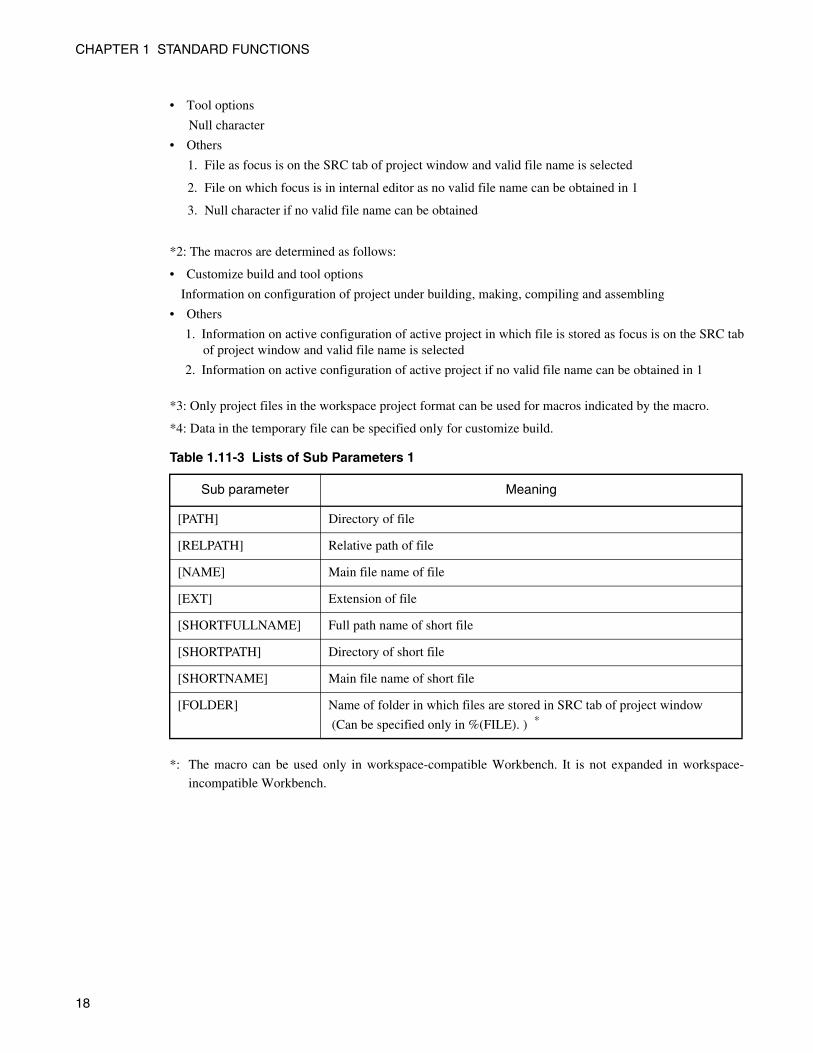
• Tool options
Null character
• Others
1. File as focus is on the SRC tab of project window and valid file name is selected
2. File on which focus is in internal editor as no valid file name can be obtained in 1
3. Null character if no valid file name can be obtained
*2: The macros are determined as follows:
• Customize build and tool options
Information on configuration of project under building, making, compiling and assembling
• Others
1. Information on active configuration of active project in which file is stored as focus is on the SRC tabof project window and valid file name is selected
2. Information on active configuration of active project if no valid file name can be obtained in 1
*3: Only project files in the workspace project format can be used for macros indicated by the macro.
*4: Data in the temporary file can be specified only for customize build.
*: The macro can be used only in workspace-compatible Workbench. It is not expanded in workspace-
incompatible Workbench.
Table 1.11-3 Lists of Sub Parameters 1
Sub parameter Meaning
[PATH] Directory of file
[RELPATH] Relative path of file
[NAME] Main file name of file
[EXT] Extension of file
[SHORTFULLNAME] Full path name of short file
[SHORTPATH] Directory of short file
[SHORTNAME] Main file name of short file
[FOLDER] Name of folder in which files are stored in SRC tab of project window
(Can be specified only in %(FILE). ) *
18
CHAPTER 1 STANDARD FUNCTIONS
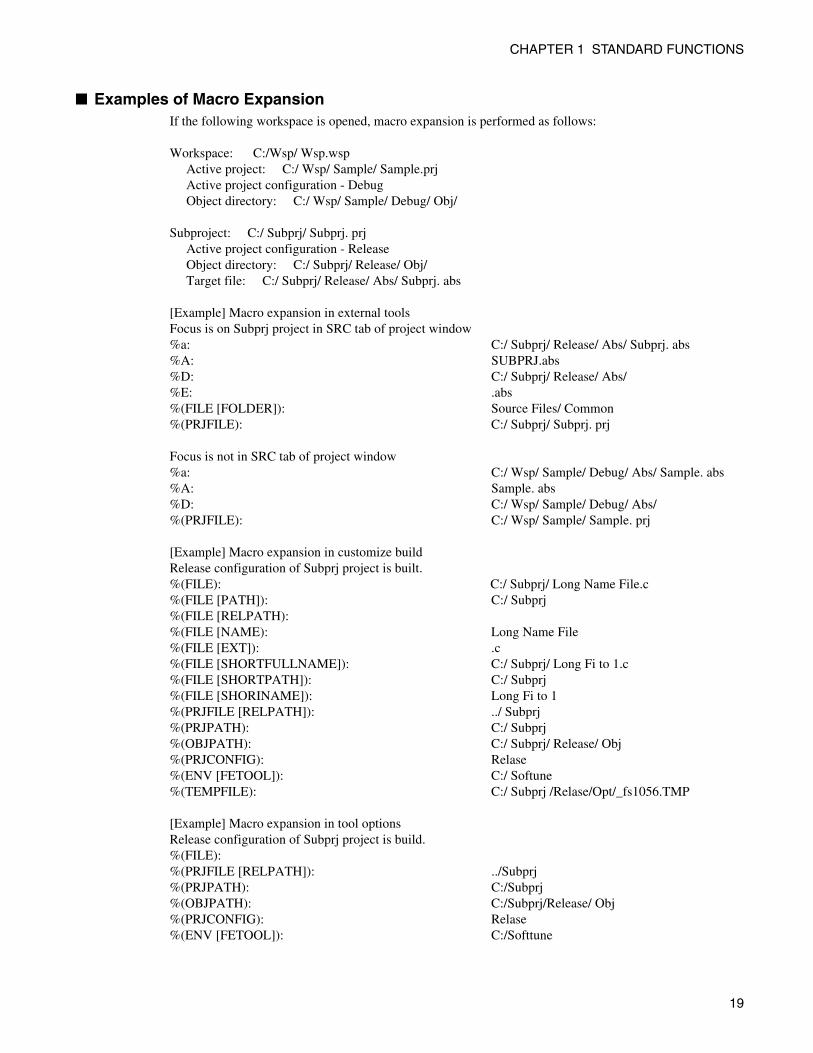
■ Examples of Macro Expansion If the following workspace is opened, macro expansion is performed as follows:
Workspace: C:/Wsp/ Wsp.wsp Active project: C:/ Wsp/ Sample/ Sample.prj Active project configuration - Debug Object directory: C:/ Wsp/ Sample/ Debug/ Obj/
Subproject: C:/ Subprj/ Subprj. prj Active project configuration - Release Object directory: C:/ Subprj/ Release/ Obj/ Target file: C:/ Subprj/ Release/ Abs/ Subprj. abs
[Example] Macro expansion in external toolsFocus is on Subprj project in SRC tab of project window%a: C:/ Subprj/ Release/ Abs/ Subprj. abs%A: SUBPRJ.abs%D: C:/ Subprj/ Release/ Abs/%E: .abs%(FILE [FOLDER]): Source Files/ Common%(PRJFILE): C:/ Subprj/ Subprj. prj
Focus is not in SRC tab of project window%a: C:/ Wsp/ Sample/ Debug/ Abs/ Sample. abs%A: Sample. abs%D: C:/ Wsp/ Sample/ Debug/ Abs/%(PRJFILE): C:/ Wsp/ Sample/ Sample. prj
[Example] Macro expansion in customize buildRelease configuration of Subprj project is built.%(FILE): C:/ Subprj/ Long Name File.c%(FILE [PATH]): C:/ Subprj%(FILE [RELPATH):%(FILE [NAME): Long Name File%(FILE [EXT]): .c%(FILE [SHORTFULLNAME]): C:/ Subprj/ Long Fi to 1.c%(FILE [SHORTPATH]): C:/ Subprj%(FILE [SHORINAME]): Long Fi to 1%(PRJFILE [RELPATH]): ../ Subprj%(PRJPATH): C:/ Subprj%(OBJPATH): C:/ Subprj/ Release/ Obj%(PRJCONFIG): Relase%(ENV [FETOOL]): C:/ Softune%(TEMPFILE): C:/ Subprj /Relase/Opt/_fs1056.TMP
[Example] Macro expansion in tool optionsRelease configuration of Subprj project is build.%(FILE):%(PRJFILE [RELPATH]): ../Subprj%(PRJPATH): C:/Subprj%(OBJPATH): C:/Subprj/Release/ Obj%(PRJCONFIG): Relase%(ENV [FETOOL]): C:/Softtune
19
CHAPTER 1 STANDARD FUNCTIONS
1.12 Setting Operating Environment
This section describes the functions for setting the SOFTUNE Workbench operating environment.
■ Operating Environment Set the environment variables for SOFTUNE Workbench and some basic items for the Project.
To set the operating environment, use the [Setup]-[Development] command.
• Environment Variables
Environment variables are variables that are referred to mainly using the language tools activated fromSOFTUNE Workbench. The semantics of an environment variable are displayed in the lower part of theSetup dialog. However, the semantics are not displayed for environment variables used by tools addedlater to SOFTUNE Workbench.
When SOFTUNE Workbench and the language tools are installed in a same directory, it is not especiallynecessary to change the environment variable setups.
• Basic setups for Project
The following setups are possible.
• Open the previously worked-on Project at start up
When starting SOFTUNE Workbench, it automatically opens the last worked-on Project.
• Display options while compiling/assembling
Compile options or assemble options can be viewed in the Output window.
• Save dialog before closing Project
Before closing the Project, a dialog asking for confirmation of whether or not to save the Project to thefile is displayed. If this setting is not made, SOFTUNE Workbench automatically saves the Projectwithout any confirmation message.
• Save dialog before compiling/assembling
Before compiling/assembling, a dialog asking for confirmation of whether or not to save a source file thathas not been saved is displayed. If this setting is not made, the file is saved automatically before compile/assemble/make/build.
• Termination message is highlighted at Make/Build
At Compile, Assemble, Make, or Build, the display color of termination messages (Abort, No Error,Warning, Error, Fatal error, or Failing During start) can be changed freely by the user.
■ Reference Section Development Environment
Note:
Because the environment variables set here are language tools for the SOFTUNE Workbench, theenvironment variables set on previous versions of SOFTUNE cannot be used. In particular, add theset values of [User Include Directory] and [Library Search Directory] to [Tool Options Settings].
20
CHAPTER 1 STANDARD FUNCTIONS
1.13 Debugger Types
This section describes the functions of SOFTUNE Workbench debuggers.
■ Debug Function SOFTUNE Workbench integrates three types of debugger: a simulator debugger, emulator debugger, and
monitor debugger. Any one can be selected depending on the requirement.
■ Simulator Debugger The simulator debugger simulates the MCU operations (executing instructions, memory space, I/O ports,
interrupts, reset, etc.) with software to evaluate a program.
It is used for evaluating an uncompleted system and operation of individual units, etc.
■ Emulator Debugger The emulator debugger is software to evaluate a program by controlling an In-Circuit Emulator (ICE) from
a host through a communications line (RS-232C or USB).
Before using this debugger, the ICE must be initialized.
■ Monitor Debugger The monitor debugger evaluates a program by putting it into an evaluation system and by communicating
with a host. An RS-232C interface and an area for the debug program are required within the evaluation
system.
For further information on the MCU-related items, see Chapter 2 and later in this manual.
21
CHAPTER 1 STANDARD FUNCTIONS
1.14 Memory Operation Functions
This section describes the memory operation functions.
■ Functions for Memory Operations • Display/Modify memory data
Memory data can be display in the Memory window and modified.
• Fill
The specified memory area can be filled with the specified data.
• Copy
The data in the specified memory area can be copied to another area.
• Compare
The data in the specified source area can be compared with data in the destination area.
• Search
Data in the specified memory area can be searched.
For further details of the above functions, refer to the Operation Manual 3.11 Memory Window.
• Display/Modify C/C++ variables
The names of variables in a C/C++ source file can be displayed in the Watch window and modified.
• Setting Watch point
By setting a watch point at a specific address, its data can be displayed in the Watch window.
For further details of the above functions, refer to the Operation Manual 3.13 Watch Window.
22
CHAPTER 1 STANDARD FUNCTIONS
1.15 Register Operations
This section describes the register operations.
■ Register Operations The Register window is opened when the [View] - [Register] command is executed. The register and flag
values can be displayed in the Register window.
For further details about modifying the register value and the flag value, refer to the Operation Manual
4.4.4 Register.
The name of the register and flag varies depending on each MCU in use. For the list of register names and
flag names for the MCU in use, refer to the Operational Manual Appendix.
■ Reference Section Register Window
23
CHAPTER 1 STANDARD FUNCTIONS
1.16 Line Assembly and Disassembly
This section describes line assembly and disassembly.
■ Line Assembly To perform line-by-line assembly (line assembly), right-click anywhere in the Disassembly window to
display the short-cut menu, and select [Line Assembly]. For further details about assembly operation, refer
to the Operation Manual 4.4.3 Assembly.
■ Disassembly To display disassembly, use the [View]-[Disassembly] command. By default, disassembly can be viewed
starting from the address pointed by the current program counter (PC). However, the address can be
changed to any desired address at start-up.
Disassembly for an address outside the memory map range cannot be displayed. If this is attempted, "???"
is displayed as the mnemonic.
■ Reference Section Disassembly Window
24
CHAPTER 1 STANDARD FUNCTIONS
1.17 Symbolic Debugging
The symbols defined in a source program can be used for command parameters (address). There are three types of symbols as follows: - Global Symbol - Static Symbol within Module (Local Symbol within Module) - Local Symbol within Function
■ Types of Symbols A symbol means the symbol defined while a program is created, and it usually has a type. Symbols become
usable by loading the debug information file.
There are three types of symbols as follows:
• Global symbol
A global symbol can be referred to from anywhere within a program. In C/C++, variables and functionsdefined outside a function without a static declaration are in this category. In assembler, symbols with aPUBLIC declaration are in this category.
• Static symbol within module (Local symbol within module)
A static symbol can be referred to only within the module where the symbol is defined.
In C/C++, variables and functions defined outside a function with a static declaration are in thiscategory. In assembler, symbols without a PUBLIC declaration are in this category.
• Local symbol within function
A local symbol within a function exists only in C/C++. A static symbol within a function and anautomatic variable are in this category.
• Static symbol within function
Out of the variables defined in function, those with static declaration.
• Automatic variable
Out of the variables defined in function, those without static declaration and parameters for the function.
■ Setting Symbol Information Symbol information in the file is set with the symbol information table by loading a debug information file.
This symbol information is created for each module.
The module is constructed for each source file to be compiled in C/C++, in assembler for each source file
to be assembled in assembler.
The debugger automatically selects the symbol information for the module to which the PC belongs to at
abortion of execution (Called "the current module"). A program in C/C++ also has information about which
function the PC belongs to.
25
CHAPTER 1 STANDARD FUNCTIONS
■ Line Number Information Line number information is set with the line number information table in SOFTUNE Workbench when a
debug information file is loaded. Once registered, such information can be used at anytime thereafter. Line
number is defined as follows:
[Source File Name] $Line Number
26
CHAPTER 1 STANDARD FUNCTIONS
1.17.1 Referring to Local Symbols
This section describes referring to local symbols and Scope.
■ Scope When a local symbol is referred to, Scope is used to indicate the module and function to which the local
symbol to be referred belongs.
SOFTUNE Workbench automatically scopes the current module and function to refer to local symbols in
the current module with preference. This is called the Auto-scope function, and the module and function
currently being scoped are called the Current Scope.
When specifying a local variable outside the Current Scope, the variable name should be preceded by the
module and function to which the variable belongs. This method of specifying a variable is called a symbol
path name or a Search Scope.
■ Moving Scope As explained earlier, there are two ways to specify the reference to a variable: by adding a Search Scope
when specifying the variable name, and by moving the Current Scope to the function with the symbol to be
referred to. The Current Scope can be changed by displaying the Call Stack dialog and selecting the parent
function. For further details of this operation, refer to the Operation Manual 4.6.6 Stack. Changing the
Current Scope as described above does not affect the value of the PC.
By moving the current scope in this way, you can search a local symbol in parent function with precedence.
■ Specifying Symbol and Search Procedure A symbol is specified as follows:
C++ symbol can be specified as follows with the scope operator:
When a symbol is specified using the module and function names, the symbol is searched. However, when
only the symbol name is specified, the search is made as follows:
• Local symbols in function in Current Scope
• The class member which can access with the this pointer
• Static symbols in module in Current Scope
• Global symbols
If a global symbol has the same name as a local symbol in the Current Scope, specify "\" or "::" at the start
of global symbol. By doing so, you can explicitly show that is a global symbol.
An automatic variable can be referred to only when the variable is in memory. Otherwise, specifying an
automatic variable causes an error.
[ [ Module Name ] [\Function name] \] Symbol Name
[ [ Class Name ] [Function name] \] Symbol Name
27
CHAPTER 1 STANDARD FUNCTIONS
1.17.2 Referring to C/C++ Variables
C/C++ variables can be specified using the same descriptions as in the source program written in C/C++
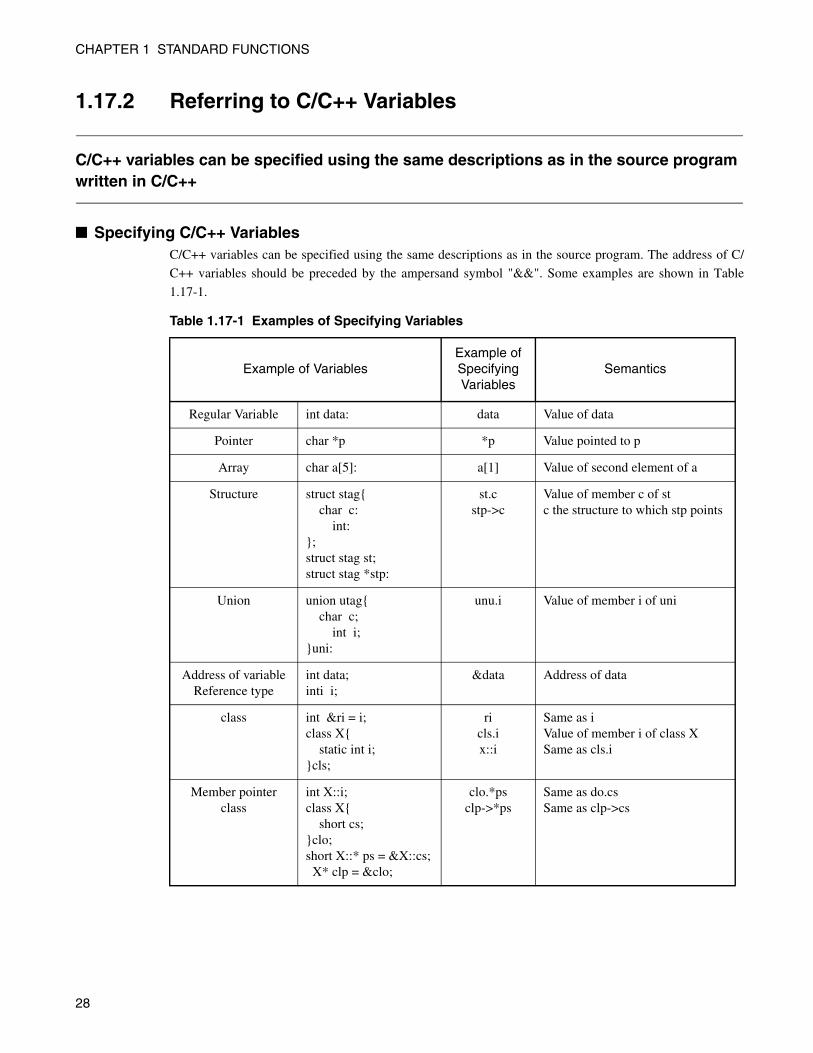
■ Specifying C/C++ Variables C/C++ variables can be specified using the same descriptions as in the source program. The address of C/
C++ variables should be preceded by the ampersand symbol "&&". Some examples are shown in Table
1.17-1.
Table 1.17-1 Examples of Specifying Variables
Example of VariablesExample of Specifying Variables
Semantics
Regular Variable int data: data Value of data
Pointer char *p *p Value pointed to p
Array char a[5]: a[1] Value of second element of a
Structure struct stag{ char c: int:};struct stag st;struct stag *stp:
st.cstp->c
Value of member c of stc the structure to which stp points
Union union utag{ char c; int i;}uni:
unu.i Value of member i of uni
Address of variable Reference type
int data;inti i;
&data Address of data
class int &ri = i;class X{ static int i;}cls;
ricls.ix::i
Same as iValue of member i of class XSame as cls.i
Member pointer class
int X::i;class X{ short cs;}clo;short X::* ps = &X::cs; X* clp = &clo;
clo.*psclp->*ps
Same as do.csSame as clp->cs
28
CHAPTER 1 STANDARD FUNCTIONS
■ Notes on C/C++ Symbols The C/C++ compiler outputs symbol information with "_" prefixed to global symbols. For example, the
symbol main outputs symbol information _main. However, SOFTUNE Workbench permits access using
the symbol name described in the source to make program debugging easier.
Consequently, a symbol name described in C/C++ and a symbol name described in assembler, which
should both be unique, may be identical.
In such a case, the symbol name in the Current Scope normally is preferred. To refer to a symbol name
outside the Current Scope, specify the symbol with the module name.
If there are duplicated symbols outside the Current Scope, the symbol name searched first becomes valid.
To refer to another one, specify the symbol with the module name.
29
CHAPTER 1 STANDARD FUNCTIONS
1.18 I/O Operations
This section describes the I/O operations.
■ I/O Operations The I/O window is opened when the [View] - [I/O] command is executed. The I/O registers value can be
displayed in the I/O window.
For further details about modifying the I/O registers value, refer to the Operation Manual 3.17 I/O Window.
30
CHAPTER 2DEPENDENCE FUNCTIONS
This chapter describes the functions depending on each debugger.
2.1 Simulator Debugger
2.2 Emulator Debugger
2.3 Monitor Debugger
2.4 Abortion of Program Execution (SIM, EML, MON)
2.5 Analyzing Program Execution (SIM, EML, MON)
31
CHAPTER 2 DEPENDENCE FUNCTIONS
2.1 Simulator Debugger
This section describes the functions of the simulator debugger.
■ Simulator Debugger The simulator debugger (later referred as simulator) simulates the MPU operations (executing instructions,
memory space, I/O ports, interrupts, reset, etc.) with software to evaluate a program.
It is used to evaluate an uncompleted system, the operation of single units, etc.
■ Simulation Range The simulator simulates the MPU operations (instruction operations, memory space, interrupts, reset, low-
power consumption mode, etc.) Peripheral I/Os, such as a timer, DMAC and serial I/O, other than the CPU
core of the actual chip are not supported as peripheral resources. I/O space to which peripheral I/Os are
connected is treated as memory space. There is a method for simulating interrupts like timer interrupts, and
data input to memory like I/O ports. For details, see "2.1.3 I/O Port Simulation" and "2.1.4 Interrupt
Simulation".
Instruction simulation
Memory simulation
I/O port simulation (Input port)
I/O port simulation (Output port)
Interrupt simulation
Reset simulation
Power-save consumption mode simulation
32
CHAPTER 2 DEPENDENCE FUNCTIONS
2.1.1 Instruction Simulation
This section describes the instruction simulation executed by SOFTUNE Workbench.
■ Instruction Simulation This simulates the operations of all instructions supported by the FR-V Family. It also simulates the
changes in memory and register values due to such instructions.
Program execution is aborted when a combined instruction is executed though execution is not possible
because of an issue restriction.
33
CHAPTER 2 DEPENDENCE FUNCTIONS
2.1.2 Memory Simulation
This section describes the memory simulation executed by SOFTUNE Workbench.
■ Memory Simulation The simulator must first secure memory space to simulate instructions because it simulates the memory
space secured in the host machine memory.
• To secure the memory area, either use the [Setup] - [Memory Map] command, or the Set Map commandin the Command window.
• Load the file output by the Linkage Editor (Load Module File) using either the [Debug] - [Load targetfile] command, or the LOAD/OBJECT command in the Command window.
■ Simulation Memory Space Memory space access attributes can be specified byte-by-byte using the [Setup] - [Memory Map]
command. The access attribute of unspecified memory space is Undefined.
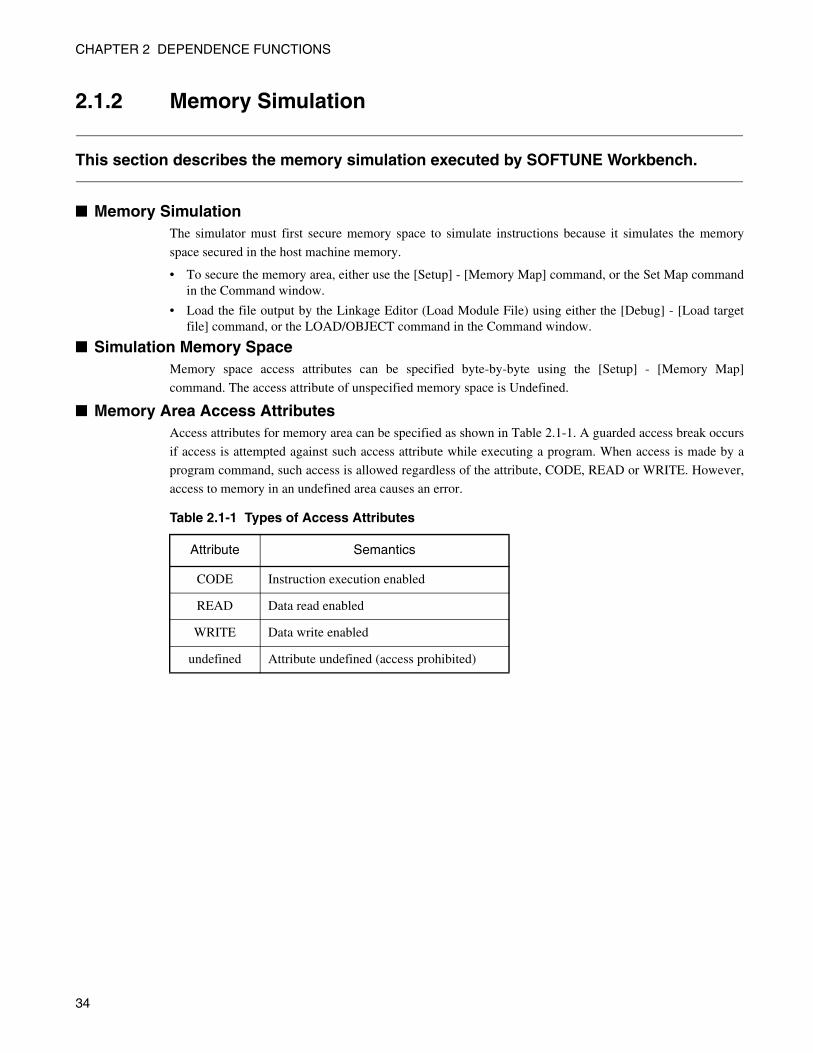
■ Memory Area Access Attributes Access attributes for memory area can be specified as shown in Table 2.1-1. A guarded access break occurs
if access is attempted against such access attribute while executing a program. When access is made by a
program command, such access is allowed regardless of the attribute, CODE, READ or WRITE. However,
access to memory in an undefined area causes an error.
Table 2.1-1 Types of Access Attributes
Attribute Semantics
CODE Instruction execution enabled
READ Data read enabled
WRITE Data write enabled
undefined Attribute undefined (access prohibited)
34
CHAPTER 2 DEPENDENCE FUNCTIONS
2.1.3 I/O Port Simulation
This section describes I/O port simulation executed by SOFTUNE Workbench.
■ I/O Port Simulation (Input Port) There are two types of simulations in I/O port simulation: input port simulation, and output port simulation.
Input port simulation has the following types:
• Whenever a program reads the specified port, data is input from the pre-defined data input source.
• Whenever the instruction execution cycle count exceeds the specified cycle count, data is input to theport.
To set an input port, use the [Setup] - [Debug Environment] - [I/O Port] command, or the Set Inport
command in the Command window.
Up to 4096 port addresses can be specified for the input port. The data input source can be a file or a
terminal (input from the terminal window). After reading the last data from the file, the data is read again
from the beginning of the file. The data is read from the input data queue of the input terminal window
when set port is read accessed if the terminal is specified.
A text file created by an ordinary text editor, or a binary file containing direct code can be used as the data
input file. Text files are composed of numbers 0 to 9 and the letters of the alphabet A to F and cannot have
delimiters or restore codes (CR codes). Errors will occur if other characters (spaces, commas, tabs, etc.) are
included. When using a binary file, select the binary radio button in the input port dialog.
■ I/O Port Simulation (Output Port) At output port simulation, whenever a program writes data to the specified port, writing is executed to the
specified data output destination.
To set an output port, either use the [Setup] - [Debug Environment] - [I/O Port] command, or the Set
Outport command in the Command window.
Up to 4096 port addresses can be set as output ports. Select either a file or terminal (Output Terminal
window) as the data output destination.
A destination file must be either a text file that can be referred to by regular editors, or a binary file. To
output a binary file, select the Binary radio button in the Output Port dialog.
35
CHAPTER 2 DEPENDENCE FUNCTIONS
2.1.4 Interrupt Simulation
This section describes interrupt simulation executed by SOFTUNE Workbench.
■ Interrupt Simulation This simulates the MPU operation for an interrupt request. The correspondence between the cause of each
interrupt and the trap type (TT) number is made by referring to the install file read at simulator start-up.
The following types can be used to allow an interrupt to occur.
• When the instruction is executed as many cycles as the specified cycle count while executing a program(executing execution commands), generate an interrupt corresponding to the specified interrupt numberto reset the interrupt generating condition.
• Whenever the instruction executing cycle count exceeds the specified cycle, an interrupt continues to begenerated.
The type of interrupt can be set using either the [Setup] - [Debug Environment] - [Interrupt] command, or
the Set Interrupt command in the Command window. If an interrupt is masked by an interrupt-enabled flag
when the interrupt generating condition is met, the interrupt is generated after canceling the mask. When an
interrupt is generated while executing a program, an interrupt cause number is displayed on the Status Bar.
Furthermore, the simulator supports the MPU operation for interrupt requests for the following exception
processing.
• Privileged instruction exception
Executes privileged instruction when the register PSR.S is bit 0.
• Illegal instruction exception
Executes instructions that have not been implemented.
• Floating-point decimal invalid exception
Executes instruction accessing the register FR or the floating-point decimal instruction when the registerPSR.EF = bit 0 and PSR.EM = bit 0.
• Media invalid exception
Executes instruction accessing the register FR or the media instruction when the register PSR EM = bit0.
• Memory address unsort exception
Accesses the unsort executable address using the load/store instruction.
Accesses the unsort memory address using the control transmission instruction.
• Register exception
Specifies the address that is not allowed for specifying register in the instruction field. Un-implementedregister access.
• Floating-point decimal exception
IEEE754 exception occurred because of the execution of the floating-point decimal instruction.
Execution of the unimplemented floating-point decimal instruction.
Accesses unimplemented register using the floating-point decimal instruction.
• Media exception
Overflow occurred because of the execution of the media instruction.
Accesses the unimplemented register using the media instruction.
Accesses the unsort executable address using the media instruction.
36
CHAPTER 2 DEPENDENCE FUNCTIONS
• Division exception
Zero division occurred when executing a division instruction.
Overflow occurred because of execution of the division instruction.
• Commit exception
COMMIT instruction execution when detecting an exception using the Non-exception instruction.
37
CHAPTER 2 DEPENDENCE FUNCTIONS
2.1.5 Reset Simulation
This section describes the reset simulation executed by SOFTUNE Workbench.
■ Reset Simulation The simulator simulates the MPU operation when a reset signal is input to the MPU by using either the
[Debug] - [Reset of MPU] command, or the Reset command in the Command window. This initializes
registers.
38
CHAPTER 2 DEPENDENCE FUNCTIONS
2.1.6 Low-Power Consumption Mode Simulation
This section describes the low-power consumption mode simulation executed by SOFTUNE Workbench.
■ Low-Power Consumption Mode Simulation The MPU enters the low-power consumption mode in accordance with the MPU instruction operation
(Write to PDM field of hardware status register). Once in the PLL operation mode or PLL stop mode, a
message ("sleep" for PLL operation mode, "stop" for PLL stop mode) is displayed on the Status Bar. The
loop keeps running until either an interrupt request is generated, or the [Run] - [Abort] command is
executed. Each cycle of the loop increments the count by 1. During this period, I/O port processing can be
operated.
39
CHAPTER 2 DEPENDENCE FUNCTIONS
2.2 Emulator Debugger
This section describes the functions of the emulator debugger.
■ Emulator Debugger The emulator debugger (later referred as emulator) is software to evaluate a program by controlling an ICE
from a host via a communications line (RS-232C, USB).
Before using this emulator, the ICE must be initialized.
For further details, refer to the Operation Manual Appendix B Download Monitor Program.
40
CHAPTER 2 DEPENDENCE FUNCTIONS
2.2.1 Notes on Executing Program
There are several points to note about program execution commands in the emulator.
■ Restrictions when Suspended by Software Break When there is a software break at the current PC location, if either the [Run] - [Go] command or the Go
command is executed, the emulator performs one execution step internally, and then executes the program
in batch processing.
41

CHAPTER 2 DEPENDENCE FUNCTIONS
2.2.2 Cache Control
This section describes cache control in the emulator debugger.
■ Cache ControlThe FR-V has and holds the instruction cache and data cache separately. When a program using cache is
executed, the following executions may cause damage to the coherency between cache and memory.
• When rewriting codes using a memory operation command or file load
• When memory data is changed in other than the debug CPU
For that reason, the debugger supports a function of matching data contents between memory and cache.
The debugger has the following three commands.
• Flush data cache (reflects the data cache contents to the memory)
• Invalidation of data cache (discards the data cache contents)
• Invalidation of instruction cache (discards the instruction cache contents)
When rewriting to the memory via the debugger, data access changes the memory contents. For this reason,
the changed contents may be reflected only to the data cache, and data contents will not match between
data cache and memory. In such cases, the "flush of data cache" command enables reflection of the data
cache contents to the memory.
If these changes (such as one line assembly) are performed in the code region, the changed contents are not
reflected to the instruction cache. When reflecting the changed contents at program execution the user
must flush the data cache, and invalidate the instruction cache.
Follow the procedure below.
1) Flush the data cache.
2) Invalidate the instruction cache.
For details on cache operations and settings, refer to Sections 4.6.4 Cache Control; and 4.7.2.3
Environment Setting Dialog in the SOFTUNE Workbench Operation Manual, and to sections 1.27 Set
Cache to 1.30 Invalidate Cache in the SOFTUNE Workbench Command Reference Manual.
■ Executing commandsUse GUI or a command to execute commands.
• GUI
Select [Debug] - [Cache Control].
• command
FLUSH CACHEINVALIDATE CACHE
42

CHAPTER 2 DEPENDENCE FUNCTIONS
■ Automatic Execution of Instruction Cache InvalidationThe debugger has the function of automatically executing of the invalidation instruction cache.
Use GUI or a command to set it.
• GUI
Select the cache tab in the debug environment setting dialog box opened using the [Environment] -[Debugging Environment] commands.
• command
SET CACHE
43

CHAPTER 2 DEPENDENCE FUNCTIONS
2.2.3 MMU Setting
This section describes MMU setting control in the emulator debugger.
■ MMU Setting Specifies whether to enable MMU setting or not when the program stop, in the chip with MMU.
Please open the "Setup debug environment" dialog by [Setup] - [Debug Environment] command and clear
"Enable MMU functions while break" check box in the MMU tab, if you want to write data in write-
protected area with MMU.
44
CHAPTER 2 DEPENDENCE FUNCTIONS
2.2.4 Command Execution while Executing Program
This section describes command execution while executing a program in the emulator.
■ Command Execution while Executing Program When executing a program using the [Run] - [Go] command, the Status Bar displays "Execute" to show
that the program is running.
Certain commands can be executed in this circumstances (they vary with the type of debugger).
The execution procedures are the same, but some commands cannot be executed and some can be executed
but are subject to restrictions.
To forcibly terminate the program, use the [Run] - [Abort] command.
Note that in the emulator debugger, memory Read/Write is re-executed while executing a program after
permitting the MPU to break once for access.
45
CHAPTER 2 DEPENDENCE FUNCTIONS
2.3 Monitor Debugger
This section describes the functions of the monitor debugger.
■ Monitor Debugger The monitor debugger performs debugging by putting the target monitor program for debugging into the
target system and by communicating with the host.
Before using this debugger, the target monitor program must be ported to the target hardware.
46
CHAPTER 2 DEPENDENCE FUNCTIONS
2.3.1 Resources Used by Monitor Program
The monitor program of the monitor debugger uses the I/O resources listed below. The target hardware must have these resources available for the monitor program.
■ Required Resources The following resources are required to build the monitor program into the target hardware.
Table 2.3-1 Required Resources
1 UART RequiredFor communication with host computer4800/9600/19200/38400/56000/57600/115200/128000/256000 baud
2 Monitor ROM Required 44 KB required (For further details, see Link Map file under Sample program.)
3 Work RAM Required 5 KB required (For further details, see Link Map file under Sample program.)
4ExternalInterrupt Switch
OptionalUsed for suspending program forcibly. If not implemented forced termination only can be performed by reset, etc.
5 Timer OptionalUsed by SET TIMER/SHOW TIMER.Requires 32-bit timer in 1 us.
47
CHAPTER 2 DEPENDENCE FUNCTIONS
2.3.2 Cache Control
This section describes cache control in the monitor debugger.
■ Cache ControlThe FR-V has and holds the instruction cache and data cache separately. When a program using cache is
executed, the following executions may cause damage to the coherency between cache and memory.
• When rewriting codes using a memory operation command or file load
• When memory data is changed in other than the debug CPU
For that reason, the debugger supports a function of matching data contents between memory and cache.
The debugger has the following three commands.
• Flush data cache (reflects the data cache contents to the memory)
• Invalidation of data cache (discards the data cache contents)
• Invalidation of instruction cache (discards the instruction cache contents)
When rewriting to the memory via the debugger, data access changes the memory contents. For this reason,
the changed contents may be reflected only to the data cache, and data contents will not match between
data cache and memory. In such cases, the "flush of data cache" command enables reflection of the data
cache contents to the memory.
If these changes (such as one line assembly) are performed in the code region, the changed contents are not
reflected to the instruction cache. When reflecting the changed contents at program execution the user
must flush the data cache, and invalidate the instruction cache.
Follow the procedure below.
1) Flush the data cache.
2) Invalidate the instruction cache.
For details on cache operations and settings, refer to Sections 4.6.4 Cache Control; and 4.7.2.3
Environment Setting Dialog in the SOFTUNE Workbench Operation Manual, and to sections 1.27 Set
Cache to 1.30 Invalidate Cache in the SOFTUNE Workbench Command Reference Manual.
■ Executing CommandsUse GUI or a command to execute commands.
• GUI
Select [Debug] - [Cache Control].
• command
FLUSH CACHEINVALIDATE CACHE
48
CHAPTER 2 DEPENDENCE FUNCTIONS
■ Automatic Execution of Instruction Cache InvalidationThe debugger has the function of automatically executing of the invalidation instruction cache.
Use GUI or a command to set it.
• GUI
Select the cache tab in the debug environment setting dialog box opened using the [Environment] -[Debugging Environment] commands.
• command
SET CACHE
49
CHAPTER 2 DEPENDENCE FUNCTIONS
2.3.3 MMU Setting
This section describes MMU setting control in the monitor debugger.
■ MMU Setting Specifies whether to enable MMU setting or not when the program stop, in the chip with MMU.
Please open the "Setup debug environment" dialog by [Setup] - [Debug Environment] command and clear
"Enable MMU functions while break" check box in the MMU tab, if you want to write data in write-
protected area with MMU.
50
CHAPTER 2 DEPENDENCE FUNCTIONS
2.3.4 Notes on Executing Program
There are several points to note about program execution commands in the monitor debugger.
■ Restrictions when Suspended by Software Break When there is a software break at the current PC location, if either the [Run] - [Go] command or the Go
command is executed, the emulator performs one execution step internally, and then executes the program
in batch processing.
51
CHAPTER 2 DEPENDENCE FUNCTIONS
2.4 Abortion of Program Execution (SIM, EML, MON)
When program execution is suspended, the address where the break occurred and the break factor are displayed.
■ Abortion of Program Execution When program execution is suspended, the address where the break occurred and the break factor are
displayed.
In the emulator debugger, the following factor can suspend program execution.
• Software Breaks
• Hardware Breaks
• External Trigger Breaks
• Data Break Points
• Forced Break
• Breaks caused by detection of the CPU stopped state
In the simulator debugger, the following factors can suspend program execution.
• Break Points
• Data Break Points
• Guarded Access Breaks
• Forced Break
• Break by Issue Restriction
• Break by Conflict
In the monitor debugger, the following factors can suspend program execution.
• Software Breaks
• Hardware Break
• Data Break Points
52
CHAPTER 2 DEPENDENCE FUNCTIONS
2.4.1 Software Breaks (EML, MON)
A software break is a function to make a break by executing an instruction embedded in memory. The break occurs before executing the instruction at the specified address.
■ Software Breaks With the emulator, you can set 4096 points for the software break points. With the monitor debugger, you
can set 20 points for the software break points. See 2.3.1 Resources Used by Monitor Program.
Software breaks can be controlled by one of the following:
• [Run] - [Breakpoints] - [Code] command
• Setting break points in Source window
• Setting break points in Disassemble window
• Set Break/Soft command
When a break occurs due to a software break, the following message is displayed in the Status Bar.
Break at Address breakpoint
■ Notes on Software Breaks There are three points to note when using software break point.
• Software breaks cannot be set in read only areas, such as ROM. If an attempt is made to do so, a verifyerror occurs at program startup (continuous execution in batch processing, step execution, etc.).
• Always set a software break at the parallel instruction starting address. Setting a software break point inthe middle of an instruction, may cause a software error.
• The current line of the source in the source window is offset and displayed in order to clearly show thenext instruction executed in the parallel instruction when the software break is set at the starting addressof the parallel instruction and the program aborts the execution because of this reason.
53
CHAPTER 2 DEPENDENCE FUNCTIONS
2.4.2 Hardware Breaks (EML, MON)
A hardware break is a break point achieved by monitoring the chip bus using hardware. A hardware break suspends the instruction operation immediately before executing the specified address instruction.
■ Hardware Breaks A maximum of three hardware break points can be set.
Instruction breaks can be controlled by either of the following:
• [Run] - [Breakpoints] - [Code] command
• Set Break/Hard command
When a break occurs due to a hardware break, the following message is displayed on the Status Bar.
Break at Address by hardware breakpoint
■ Notes on Hardware Breaks There are several points to note when using hardware breaks point.
• Always include the instruction starting address in the hardware break point within the specified range.Otherwise, the break may not occur.
• Set the hardware break in the starting address of the parallel instruction using the following methods.
Set using the SET BREAK command
Set from the break point dialog
Set from the disassemble window
The current line of the source in the source window is offset and displayed in order to clearly show the
instruction executed next in the parallel instruction when the program execution is aborted because of this
reason.
54
CHAPTER 2 DEPENDENCE FUNCTIONS
2.4.3 External Trigger Break (EML)
An external trigger break is a function to suspend program execution when an external signal is input from the emulator TRIG pin.
■ External Trigger Break You can abort the execution of the program when inputting an external signal from the TRIG pin on the
front of the emulator.
When a break occurs due to an external trigger break, the following message is displayed on the Status Bar.
Break at Address by external trigger break
55
CHAPTER 2 DEPENDENCE FUNCTIONS
2.4.4 Break Points (SIM)
A break point is a program memory location where the simulator suspends the program each time the point is reached while the program is executing (while executing execution commands). Normally a break point is set in the program space (the space where the CODE attribute is specified).
■ Break Points Break points can be controlled using the [Run] - [Breakpoints] - [Code] command. When the program
reaches a break point (immediately before executing the instruction at the memory location), the simulator
executes the following processes:
1. Suspends program execution (before executing instruction)
2. Checks count of arrival time. If the count of arrival time at the specified break point has not yet been
reached, the simulator resumes the program execution. If the count of arrival time has been reached, the
simulator proceeds to step 3.
3. Displays memory location where execution suspended on Status Bar.
4. Break points set using the [Run] - [Breakpoints] - [Code] command, remain valid until canceled or
temporarily reset.
Up to 65535 break points can be set. Break points cause the program to suspend instruction operation just
before executing the instruction at the specified address. In addition to using the [Run] - [Breakpoints] -
[Code] command, break points can be set as follows:
• Setting break points in Source window
• Setting break points in Disassemble window
• Set Break command
The following message is displayed on the Status Bar when a break occurs due to a break point.
Break at Address by breakpoint
■ Notes on Simulator Break Point There are several points to note when using simulator break point.
• Set the break point in the starting address of the parallel instruction using the following methods.
Set using the SET BREAK command
Set from the break point dialog
Set from the disassemble window
The current line of the source in the source window is offset and displayed in order to clearly show the
instruction executed next in the parallel instruction when the program execution is aborted because of this
reason.
56
CHAPTER 2 DEPENDENCE FUNCTIONS
2.4.5 Data Break Points (SIM, EML, MON)
A data break point is the memory location where a program execution is suspended when data access (Read/Write) is performed while executing a program (while executing execution commands).
■ Data Break Points The simulator/emulator/monitor debugger monitors whether the specified data access is made to a data
break point while a program is executing; if such data access is made, it suspends the program. Data break
points can be controlled using either the [Run] - [Breakpoints] - [Data] command, or the Set DataBreak
command in the Command window. When specifying a data break point with a symbol, the starting address
of that symbol becomes the data break point. You can set a maximum of 65535 data break points with the
simulator and a maximum of 4 with the emulator and monitor debugger.
When a break occurs due to a data break point, the following message is displayed.
Break at Address by DataBreak at Access Address
■ Writing to Data Break Point When data is written to a data break point, the simulator executes the following processes:
1. Suspends program execution after completing instruction execution
2. This checks whether the position of the bit that specified 1 with the mask data and the bit value that was
specified by the data match for the data writing to. With the simulator, it checks the size of the data
writing to. If conditions are met, the simulator proceeds to step 3.
3. Checks access count. If the access count has not yet reached the count for the specified data break point,
the simulator resumes the program execution. If the count has been reached, the simulator proceeds to
step 4.
4. If program execution is suspended by reaching access count, on Status Bar, displays memory location of
data break point and of instruction writing to it.
5. Displays memory location executed next
■ Reading from Data Break Point When reading from a data break point, the simulator executes the following processes:
1. Suspends program execution after completing execution of the instruction
2. This checks whether the position of the bit that specified 1 with the mask data and the bit value that was
specified by the data match for the data writing to. With the simulator, it checks the size of the data
writing to. If conditions are met, the simulator proceeds to step 3.
3. Checks access count. If the access count has not yet reached the count for the specified data break point,
the simulator resumes the program execution. If the count has been reached, the simulator proceeds to
step 4.
4. If program execution is suspended by reaching count, on Status Bar, displays memory location of data
break point and of instruction reading from it
5. Displays memory location executed next
57
CHAPTER 2 DEPENDENCE FUNCTIONS
■ Notes on Using Data Breaks There are two points to note when using data break points as follows:
• If an automatic variable within a C function is specified, a data break is set at the address where the
automatic variable is held. Therefore, the data break remains valid even after the specified automatic
variable becomes invalid (after exiting function), causing a break due to unexpected access.
• To allow access to a variable in C to cause a break, specify the variable address by putting an ampersand
symbol "&&" immediately before the variable symbol.
58
CHAPTER 2 DEPENDENCE FUNCTIONS
2.4.6 Guarded Access Breaks (SIM)
A guarded access break suspends a executing program when accessing in violation of the access attribute set by using the [Setup] - [Memory Map] command, and accessing a guarded area (access-disabled area in undefined area).
■ Guarded Access Breaks Guarded access breaks are as follows:
• Code Guarded
An instruction has been executed for an area having no code attribute.
• Read Guarded
A read has been attempted from the area having no read attribute.
• Write Guarded
A write has been attempted to an area having no write attribute.
If a guarded access occurs while executing a program, the following message is displayed on the Status Bar
and the program execution suspended.
Break at Address by guarded access {code/read/write} at Access Address
59
CHAPTER 2 DEPENDENCE FUNCTIONS
2.4.7 Forced Break (SIM, EML)
A program execution can be forcibly suspended by using the [Run] - [Abort] command.
■ Forced Break When a break occurs due to a forced break, the following message is displayed on the Status Bar.
Break at Address by command abort request
■ Forced Break in Low-Power Consumption Mode A forced break is not allowed in the emulator debugger while the MPU is in the low-power consumption
mode. When a forced break is requested by the [Run] - [Abort] command while executing a program, the
command is disregarded if the MPU is in the low-power consumption mode. If a break must occur, then
reset the factor at user system side, or reset the factor by using the [Run] - [Reset of MPU] command, after
inputting the [Run] - [Abort] command.
When the MPU enters the low-power consumption mode while executing, the status is displayed on the
Status Bar.
60
CHAPTER 2 DEPENDENCE FUNCTIONS
2.4.8 Breaks by Issue Restrictions (SIM)
Program execution is suspended when a combined instruction that was not allowed was executed in 1 parallel instruction.
■ Breaks by Issue Restrictions With the simulator debugger, program execution is suspended when a combined instruction that was not
allowed is executed in 1 parallel instruction. The following message is displayed when a break occurs
because of the issue restriction.
Break at address by violation to combine instructions
With the simulator debugger, program execution is suspended when the instruction is executed regardless
of whether it was an instruction that cannot be issued in the slot or 1 parallel instruction. The following
message is displayed when a break occurs because of the issue restriction.
Break at address by slot issue violation
Refer to the LSI specification for issue restrictions.
61
CHAPTER 2 DEPENDENCE FUNCTIONS
2.4.9 Breaks by Conflicting Writing (SIM)
The program execution is suspended when a plurality of instructions that write access the same memory or the register are executed in 1 parallel instruction.
■ Breaks by Conflict With the simulator debugger, program execution is suspended when a plurality of instructions that write
access the same memory or the register are executed in 1 parallel instruction. The following message is
displayed when a break occurs because of the conflicting writing.
Break at address by resource write-write confliction
62
CHAPTER 2 DEPENDENCE FUNCTIONS
2.4.10 Breaks Caused by Detection of the CPU Stopped State (EML)
A break caused by detection of the CPU stopped state means a break caused when a hold inhibit program interrupt factor or a software interrupt factor is detected when the system is in the interrupt inhibit state.
■ Breaks Caused by Detection of the CPU Stopped State When using a break caused by detection of the CPU stopped state, enable the CPU-stopped-state detection
function by using the following commands: [Environment] - [Set the Debugging Environment] -
[Debugging Environment]. The default value at the time of debugger activation is enabled.
When a break has occurred due to detection of the CPU stopped state, the following message is displayed
in the status bar:
Break at address by EIT (interrupt factor TT: number)
■ A Note on Breaks Caused by Detection of the CPU Stopped State Disable the CPU-stopped-state detection function when performing the following, for instance: debugging
a utility that uses the mechanism that saves the factor for the stopped state, or debugging the hardware that
responds to the stopped state.
63
CHAPTER 2 DEPENDENCE FUNCTIONS
2.5 Analyzing Program Execution (SIM, EML, MON)
You can trace the execution history to analyze the program.
■ Analyzing Program Execution The following types are available for analyzing program execution.
• Trace
• Measuring Execution Time
64
CHAPTER 2 DEPENDENCE FUNCTIONS
2.5.1 Trace (SIM, EML)
While executing a program, execution address information can be sampled and recorded in the trace buffer. This function is called trace.
■ Trace The program execution history can be deep-analyzed using the data recorded by the trace function. This
function is only available in the simulator debugger and the emulator debugger.
The trace buffer has a ring structure, so when the trace buffer becomes full, it automatically returns to the
buffer start address to overwrite existing data.
Trace Data
Tracing Function
Setting Trace
Displaying Trace Data
Displaying Format of Trace Data
Searching Trace Data
Saving Trace Data
Clearing Trace Data
Notes on Use of Tracing Function
65
CHAPTER 2 DEPENDENCE FUNCTIONS
2.5.2 Trace Data (SIM, EML)
Data sampled and recorded by tracing is called trace data. The recording format of trace data varies with each debugger.
■ Trace Data You can sample the following sizes using the emulator debugger.
• Full Trace Mode: 8 branches prior to suspending execution
• Trace trigger Mode: 4 branches before and after passing the first trigger
The following data is sampled.
• Address (32 Bits)
• Only Instruction Execution
The simulator debugger can sample trace data by 1,000 frames.
66
CHAPTER 2 DEPENDENCE FUNCTIONS
2.5.3 Tracing Function (SIM, EML)
The status of the program execution is trace measured during the period from starting execution to the end of the execution of the program. With the emulator, you can trace measure 4 branches before and after the execution of the program first passes the specified address (trace trigger).
■ Tracing Function If the trace function is enabled, data is always sampled while executing the execution command and that is
stored in the trace buffer.
With the emulator, information for 8 branches immediately before the suspension are recorded in the trace
buffer, when the program execution is suspended. Also, there is a function for starting the trace
measurement while the following program is executed.
• When the trace sampling mode is switched to trace trigger mode, this trace measures the 4 branchesbefore and after the execution of the program first passes the address (trace trigger) specified by thetrace window short cut menu [Setup] - [Trace Trigger].
The program execution is suspended by the break factor such as break point and tracing stops.
When the trace buffer is full with simulator debugger, you can break the program. This break is called a
trace buffer full break.
■ Frame Number The sampled trace data is numbered in frame units. This number is called the frame number.
When in Full Trace Mode, specify from which position to display from the trace buffer to perform using
the frame number. A 0 accompanies the trace data that was sampled last and a negative number
accompanies the trace data sampled up to the position where the trigger occurred.
When in the Trigger Trace Mode, the trace data that passed through the address setting the trigger trace
becomes 0 and positive and negative numbers accompany the preceding and anteceding trace data.
67
CHAPTER 2 DEPENDENCE FUNCTIONS
2.5.4 Setting Trace (SIM, EML)
You must set the following 3 items to perform a trace. After that, trace data will be sampled with the execution of the program. You can set this from the command window.
■ Setting Trace 1. Enable the trace function.
This is done by [Setup] - [Trace] in the trace window shortcut menu. This program will startup and will
be enabled.
2. Set the trace mode. (Only Emulator Debugger)
This is done by [Setup] - [Trace Trigger] in the trace window shortcut menu.
3. Set the trace buffer full break. (Only Simulator Debugger)
When the trace buffer is full, you can make a break. This is done using the setting dialog boxes of the
trace window shortcut menu [Setup] - [Trace].
When starting up this program, it is setup for no breaks.
68
CHAPTER 2 DEPENDENCE FUNCTIONS
2.5.5 Displaying Trace Data (SIM, EML)
Data recorded in the trace buffer can be displayed.
■ Displaying Trace Data The trace window displays how much trace data is stored in the trace buffer. Also, you can use the Show
Trace command from the command window.
With the emulator debugger, it shows the code information analyzed from the branch information as the
trace data.
69
CHAPTER 2 DEPENDENCE FUNCTIONS
2.5.6 Display Format of Trace Data (SIM, EML)
There are display formats for displaying trace buffer data:
■ Display Format of Trace Data • Display Only Instruction Execution (Specify Instruction)
• Display by Unit of Source Lines (Specify Source)
■ Display Only Instruction Execution In this mode, the instruction execution is displayed in disassembly units.
■ Display by Unit of Source Lines This mode only displays source lines.
70
CHAPTER 2 DEPENDENCE FUNCTIONS
2.5.7 Searching Trace Data (SIM, EML)
Trace data can be searched to find where data to be displayed is stored in the trace buffer.
■ Searching Trace Data Specify the search by code fetch address information. In addition, the masking function can be used with
address.
Click the Search button in the Trace window to use this function.
71
CHAPTER 2 DEPENDENCE FUNCTIONS
2.5.8 Saving Trace Data (SIM, EML)
The debugger has function of saving trace data.
■ Saving Trace DataSave the trace data to the specified file.
For details on operations, refer to Sections 3.14 Trace Window, and 4.4.8 Trace in the SOFTUNE
Workbench Operation Manual; and Section 4.11 Shoe Trace in the SOFTUNE Workbench Command
Reference Manual.
72
CHAPTER 2 DEPENDENCE FUNCTIONS
2.5.9 Clearing Trace Data (SIM, EML)
To clear trace data, use the following command.
■ Clearing Trace Data Execute the [Clear] command from the short-cut menu in the Trace window to clear trace data.
73
CHAPTER 2 DEPENDENCE FUNCTIONS
2.5.10 Notes on Use of Tracing Function (SIM, EML)
There are several points to note when displaying or searching trace data.
■ Notes on Trace Function When the emulator debugger is in use, tracing is enabled by the following:
• Output address information at fetching branch instruction
• Execution Start
• When executing branching conditions, the CCCR changes from the previous trace information.
For these reasons, note the following points when displaying and searching trace data
• When displaying disassembly, data is read from memory and processed. Therefore, the displayed datamay not be correct if the instruction is rewritten after code fetching.
74
CHAPTER 2 DEPENDENCE FUNCTIONS
2.5.11 Measuring Execution Cycle Counts (EML)
The program instruction execution cycle counts can be displayed by using either the [Analyze] - [Time Measurement] command, or the Show Timer command in the Command window.
■ Measuring Execution Cycle Counts Measures program execution cycle counts.
The measurement result can be displayed as two time values: the execution cycle counts of the preceding
program, and the total execution cycle counts of the programs (total execution cycle counts before
preceding program plus execution cycle counts of preceding program). Measurement is performed each
time a program is executed.
Clear the measured values using the Clear Timer command.
Note:
Execution cycle counts are measured in several tens of cycles at one execution. When measuringexecution cycles, set for consecutive executions of many instructions to decrease the efficacy oferrors.
75
CHAPTER 2 DEPENDENCE FUNCTIONS
2.5.12 Measuring Execution Time (SIM)
The instruction cycle count and step count of a program can be displayed by using either the [Analyze] - [Time Measurement] command, or the Show Timer command in the Command window.
■ Measuring Execution Time Measures program execution cycle count and step count.
The measurement result can be displayed as two time values: the execution time of the preceding program,
and the total execution time of the programs (total execution time before preceding program plus execution
time of preceding program). Measurement is performed each time a program is executed.
To display the execution cycle count, use the [Analyze] - [Time Measurement] command or the Show
Timer command in the Command widow. Clear the measured values using the Clear Timer command.
The counters for the instruction execution cycle count and program step count are both H'1 to
H'FFFFFFFF.
The count of the instruction execution cycle is calculated based on the basic cycle count of each instruction
described in the Programming Manual.
Since the chip internal pipeline processing and cache operation are not simulated, such counts may be
erroneous and different from those of the actual chip.
76
CHAPTER 2 DEPENDENCE FUNCTIONS
2.5.13 Measuring Execution Time (MON)
The program instruction execution time can be displayed by using either the [Analyze] - [Time Measurement] command, or the Show Timer command in the Command window.
■ Measuring Execution Time Measures program execution time.
The measurement result can be displayed as two time values: the execution time of the preceding program,
and the total execution time of the programs (total execution time before preceding program plus execution
time of preceding program). Measurement is performed each time a program is executed.
To display the execution cycle count, use either the [Analyze] - [Time Measurement] command, or the
Show Timer command in the Command window. Clear the measured values using the Clear Timer
command.
Measurement is in 1 µs units. The maximum measurement time is about 70 minutes. The measurement
result may have a ± 10 µs error.
77
CHAPTER 2 DEPENDENCE FUNCTIONS
2.5.14 Performance Measurement (EML)
The execute cycle count; pass-through count, and cache hit rate between two points can be measured. Real time measurements can be repeatedly made while the program is being executed, and after completion of the measurements, data is summed up and displayed. Using this performance measurement function, you can measure the performance of the program.
■ Performance Measurement Function The performance measurement function can measure the execute cycle count, pass-through count, and
cache hit rate between the specified two points. Using this function, you can measure the performance of
the program to be debugged.
This function is able to use when using the chip that has PA-function only.
■ Performance Measurement Function The performance measurement procedure is as shown below.
• Setting of the performance measurement range: SET PERFORMANCE
• Performance measurement: GO, STEP, CALL
• Display of the measured result: SHOW PERFORMACE
78
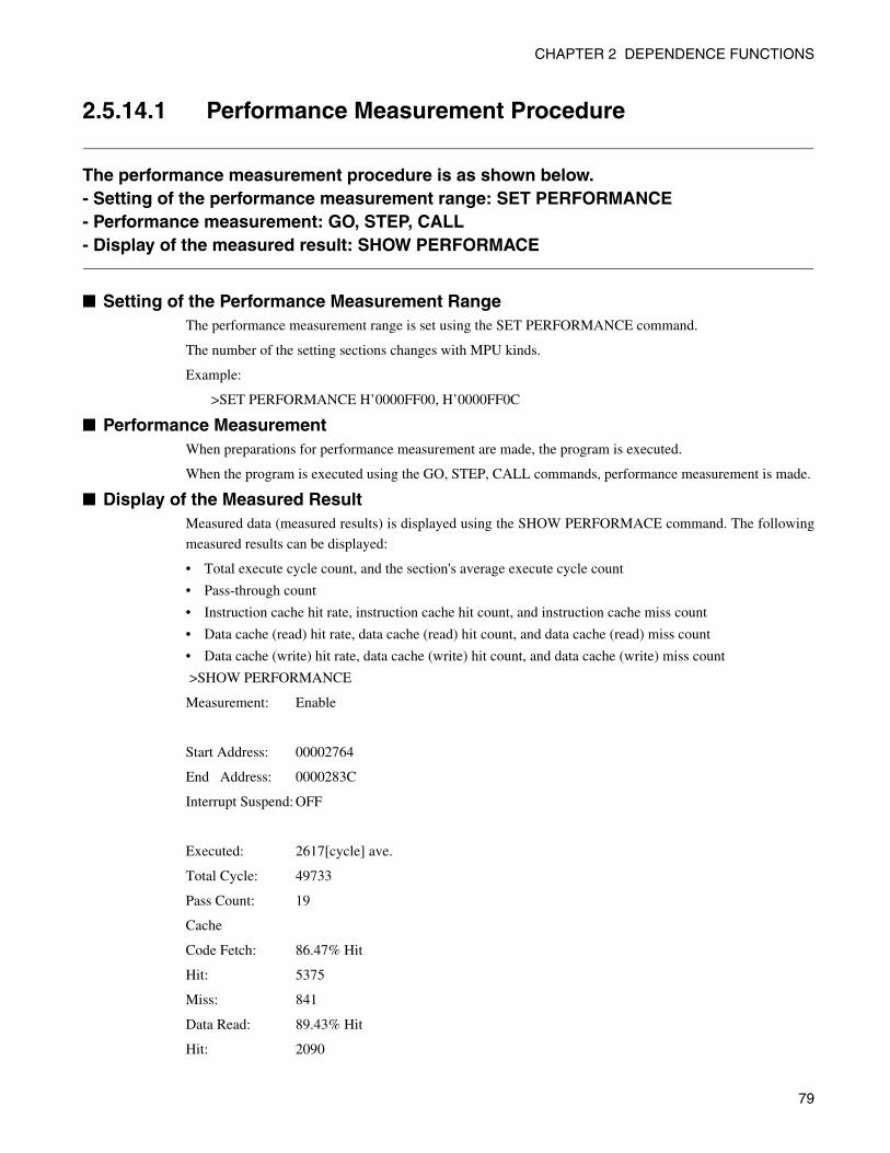
CHAPTER 2 DEPENDENCE FUNCTIONS
2.5.14.1 Performance Measurement Procedure
The performance measurement procedure is as shown below. - Setting of the performance measurement range: SET PERFORMANCE - Performance measurement: GO, STEP, CALL - Display of the measured result: SHOW PERFORMACE
■ Setting of the Performance Measurement Range The performance measurement range is set using the SET PERFORMANCE command.
The number of the setting sections changes with MPU kinds.
Example:
>SET PERFORMANCE H’0000FF00, H’0000FF0C
■ Performance Measurement When preparations for performance measurement are made, the program is executed.
When the program is executed using the GO, STEP, CALL commands, performance measurement is made.
■ Display of the Measured Result Measured data (measured results) is displayed using the SHOW PERFORMACE command. The following
measured results can be displayed:
• Total execute cycle count, and the section's average execute cycle count
• Pass-through count
• Instruction cache hit rate, instruction cache hit count, and instruction cache miss count
• Data cache (read) hit rate, data cache (read) hit count, and data cache (read) miss count
• Data cache (write) hit rate, data cache (write) hit count, and data cache (write) miss count
>SHOW PERFORMANCE
Measurement: Enable
Start Address: 00002764
End Address: 0000283C
Interrupt Suspend: OFF
Executed: 2617[cycle] ave.
Total Cycle: 49733
Pass Count: 19
Cache
Code Fetch: 86.47% Hit
Hit: 5375
Miss: 841
Data Read: 89.43% Hit
Hit: 2090
79
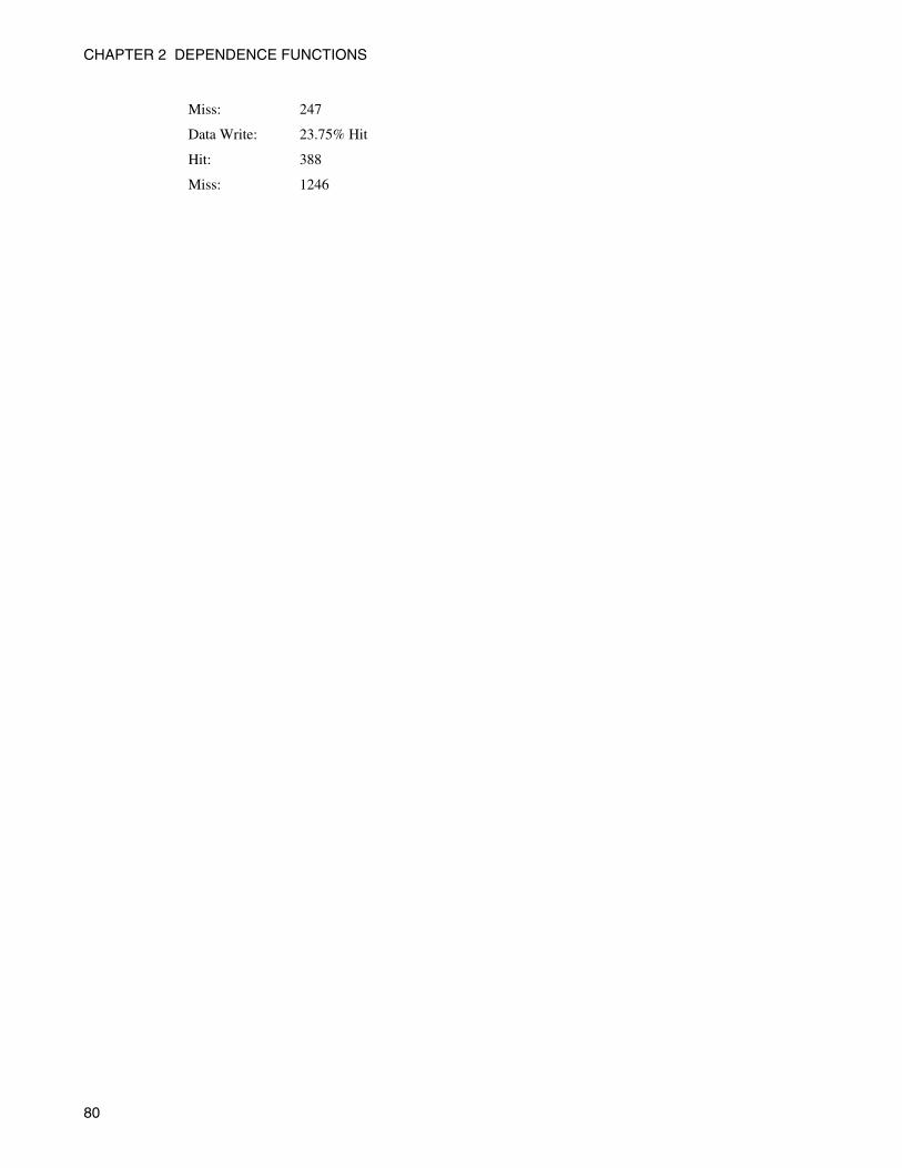
CHAPTER 2 DEPENDENCE FUNCTIONS
Miss: 247
Data Write: 23.75% Hit
Hit: 388
Miss: 1246
80
CHAPTER 3MULTI-CORE
DEVELOPMENTENVIRONMENT
In this chapter, function for development environment for multi-core is explained.
3.1 Development Environment for Multi-core
3.2 Object Programming Model
3.3 Target File
3.4 Multi-core Project
3.5 Session
3.6 Debugging Multi-core
3.7 Duplication of Workbench
3.8 Command
3.9 Cautions for Multi-core Debugging
81
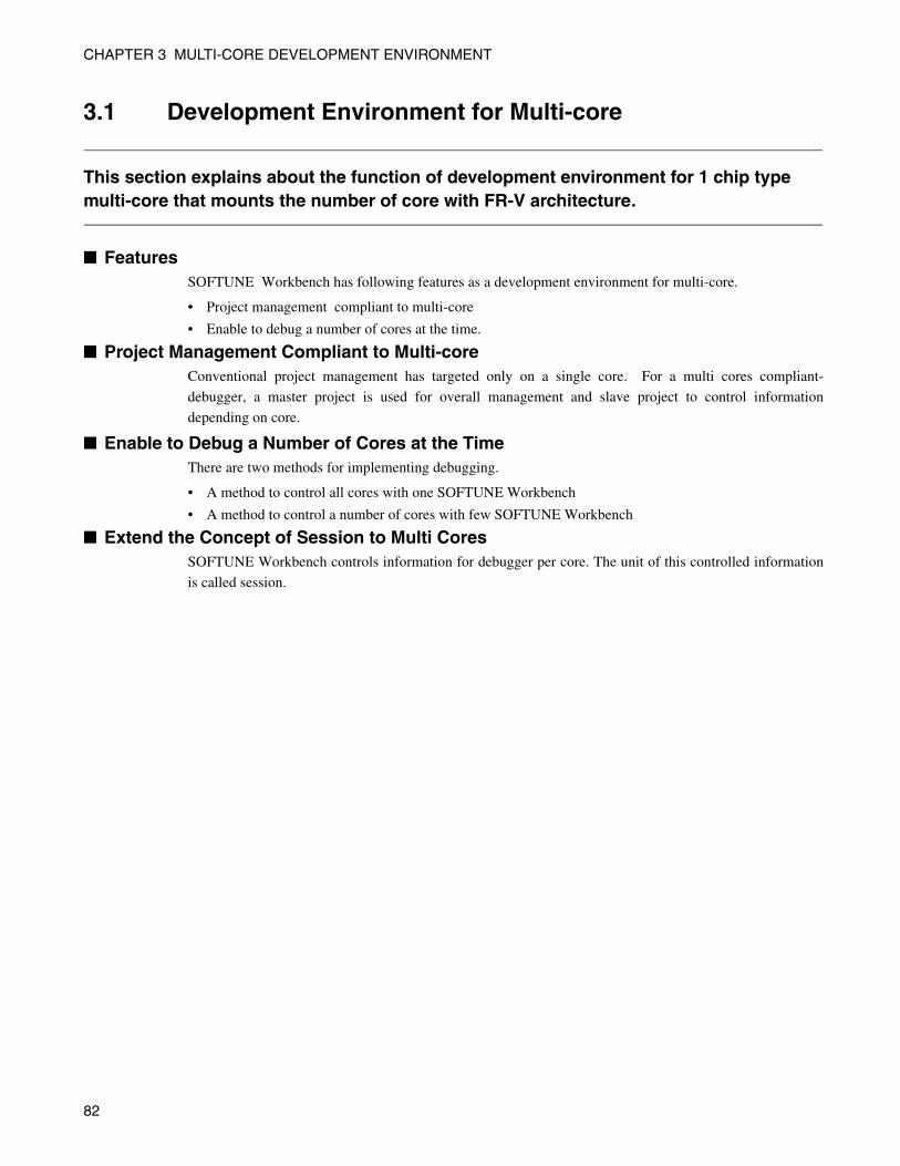
CHAPTER 3 MULTI-CORE DEVELOPMENT ENVIRONMENT
3.1 Development Environment for Multi-core
This section explains about the function of development environment for 1 chip type multi-core that mounts the number of core with FR-V architecture.
■ FeaturesSOFTUNE Workbench has following features as a development environment for multi-core.
• Project management compliant to multi-core
• Enable to debug a number of cores at the time.
■ Project Management Compliant to Multi-core Conventional project management has targeted only on a single core. For a multi cores compliant-
debugger, a master project is used for overall management and slave project to control information
depending on core.
■ Enable to Debug a Number of Cores at the TimeThere are two methods for implementing debugging.
• A method to control all cores with one SOFTUNE Workbench
• A method to control a number of cores with few SOFTUNE Workbench
■ Extend the Concept of Session to Multi CoresSOFTUNE Workbench controls information for debugger per core. The unit of this controlled information
is called session.
82
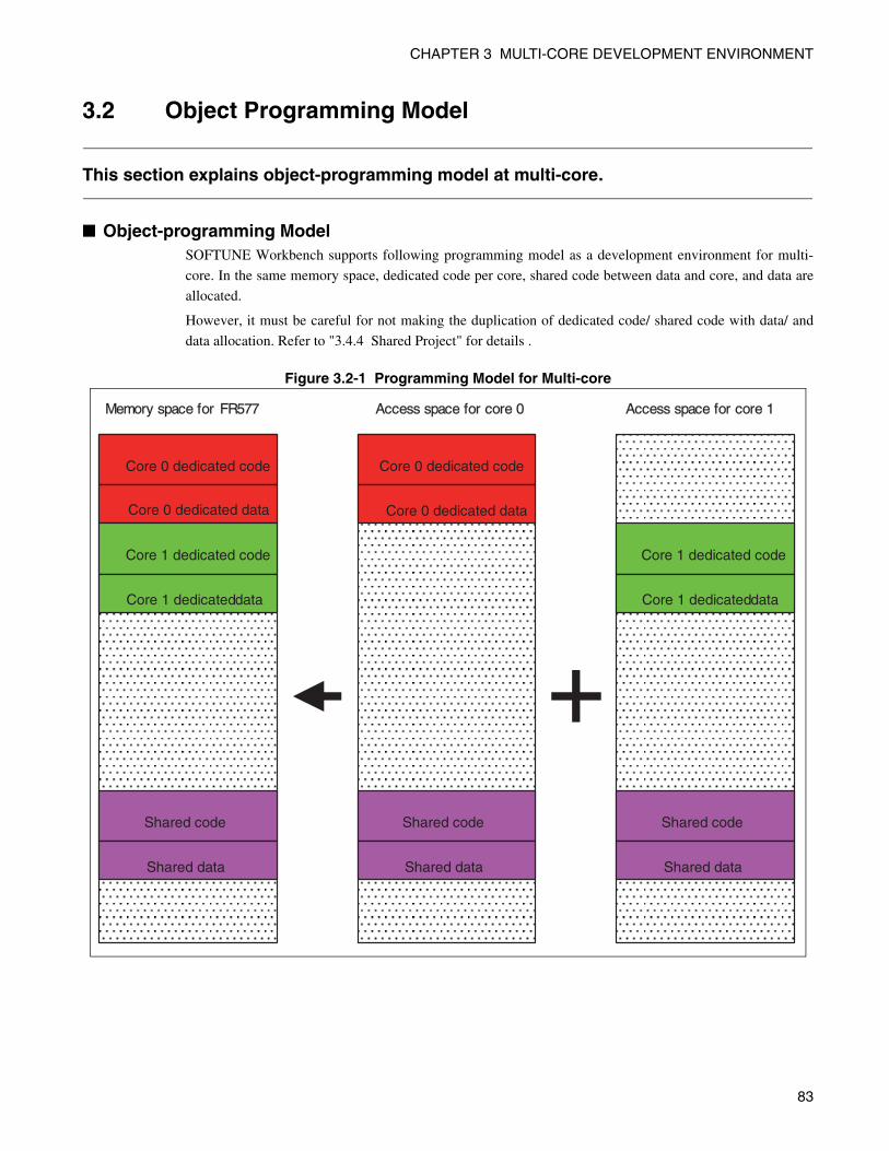
CHAPTER 3 MULTI-CORE DEVELOPMENT ENVIRONMENT
3.2 Object Programming Model
This section explains object-programming model at multi-core.
■ Object-programming ModelSOFTUNE Workbench supports following programming model as a development environment for multi-
core. In the same memory space, dedicated code per core, shared code between data and core, and data are
allocated.
However, it must be careful for not making the duplication of dedicated code/ shared code with data/ and
data allocation. Refer to "3.4.4 Shared Project" for details .
Figure 3.2-1 Programming Model for Multi-core
Access space for core 0
Core 0 dedicated code
Core 0 dedicated data
Shared code
Shared data
Access space for core 1
Core 1 dedicated code
Core 1 dedicated data
Shared code
Shared data
Core 0 dedicated code
Core 0 dedicated data
Core 1 dedicated code
Core 1 dedicated data
Shared code
Shared data
Memory space for FR577
83
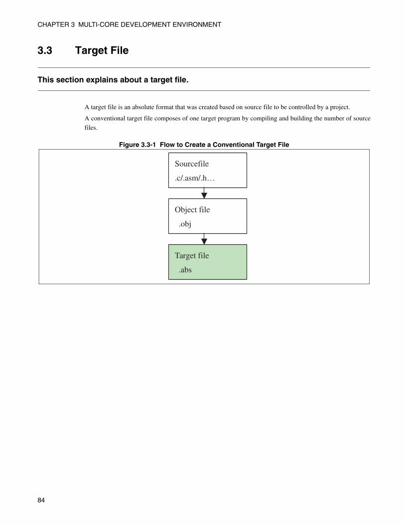
CHAPTER 3 MULTI-CORE DEVELOPMENT ENVIRONMENT
3.3 Target File
This section explains about a target file.
A target file is an absolute format that was created based on source file to be controlled by a project.
A conventional target file composes of one target program by compiling and building the number of source
files.
Figure 3.3-1 Flow to Create a Conventional Target File
Sourcefile
.c/.asm/.h…
Target file
.abs
Object file
.obj
84
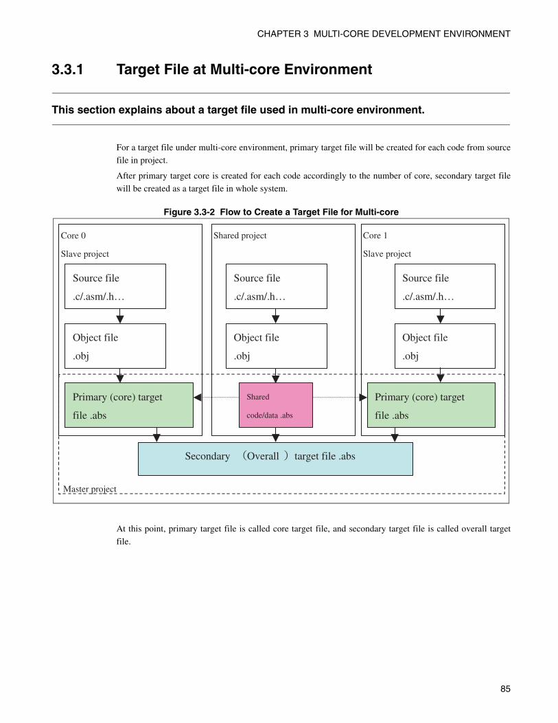
CHAPTER 3 MULTI-CORE DEVELOPMENT ENVIRONMENT
3.3.1 Target File at Multi-core Environment
This section explains about a target file used in multi-core environment.
For a target file under multi-core environment, primary target file will be created for each code from source
file in project.
After primary target core is created for each code accordingly to the number of core, secondary target file
will be created as a target file in whole system.
Figure 3.3-2 Flow to Create a Target File for Multi-core
At this point, primary target file is called core target file, and secondary target file is called overall target
file.
Source file
.c/.asm/.h…
Primary (core) target
file .abs
Object file
.obj
Core 0
Slave project
Source file
.c/.asm/.h…
Primary (core) target
file .abs
Object file
.obj
Core 1
Slave project
Source file
.c/.asm/.h…
Shared
code/data .abs
Object file
.obj
Shared project
Secondary Overall target file .abs
Master project
85
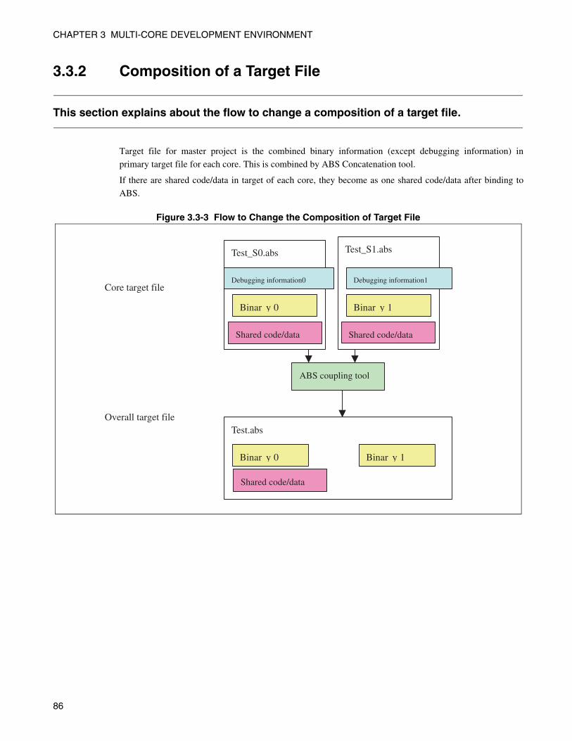
CHAPTER 3 MULTI-CORE DEVELOPMENT ENVIRONMENT
3.3.2 Composition of a Target File
This section explains about the flow to change a composition of a target file.
Target file for master project is the combined binary information (except debugging information) in
primary target file for each core. This is combined by ABS Concatenation tool.
If there are shared code/data in target of each core, they become as one shared code/data after binding to
ABS.
Figure 3.3-3 Flow to Change the Composition of Target File
Test_S0.abs
Debugging information0
Binar y 0
Test_S1.abs
Debugging information1
Binar y 1
Test.abs
Binar y 0 Binar y 1
ABS coupling tool
Shared code/data Shared code/data
Shared code/data
Core target file
Overall target file
86
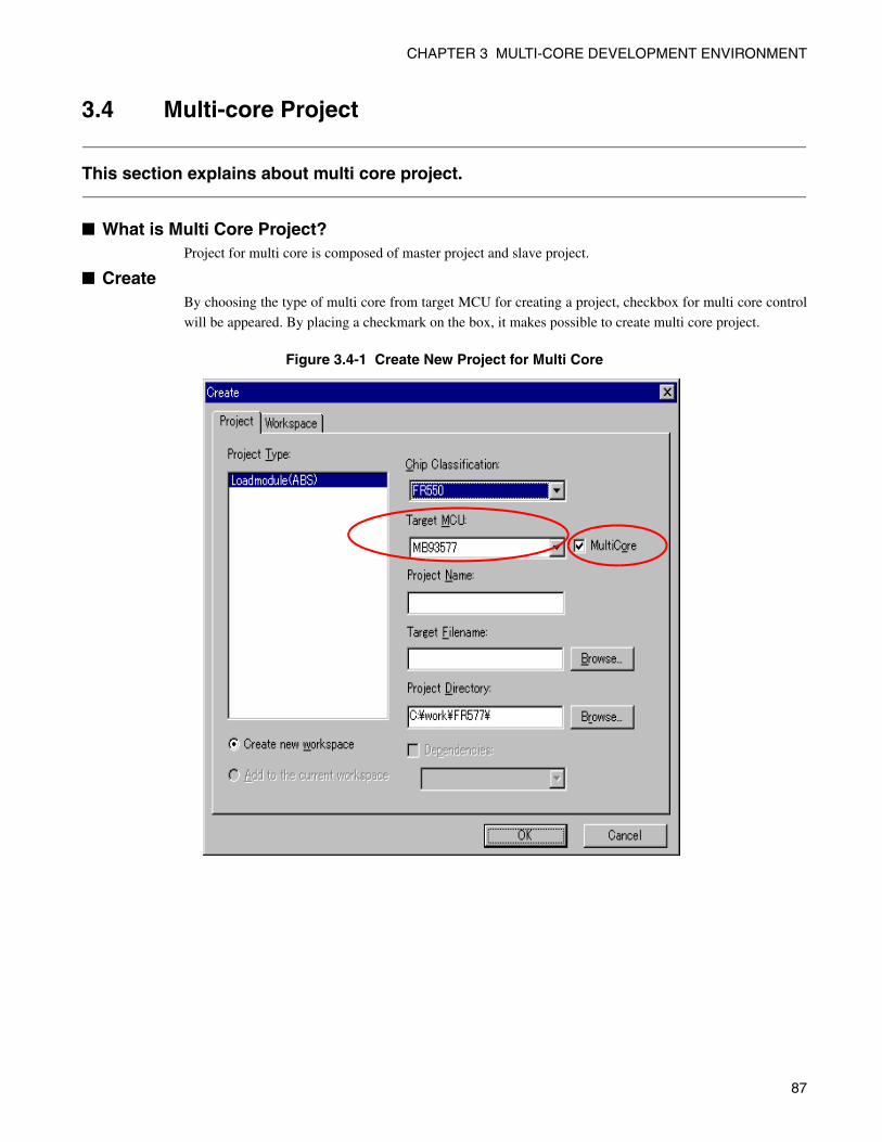
CHAPTER 3 MULTI-CORE DEVELOPMENT ENVIRONMENT
3.4 Multi-core Project
This section explains about multi core project.
■ What is Multi Core Project?Project for multi core is composed of master project and slave project.
■ CreateBy choosing the type of multi core from target MCU for creating a project, checkbox for multi core control
will be appeared. By placing a checkmark on the box, it makes possible to create multi core project.
Figure 3.4-1 Create New Project for Multi Core
87
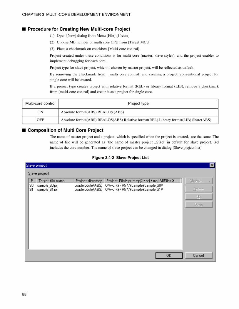
CHAPTER 3 MULTI-CORE DEVELOPMENT ENVIRONMENT
■ Procedure for Creating New Multi-core Project(1) Open [New] dialog from Menu [File]-[Create]
(2) Choose MB number of multi core CPU from [Target MCU]
(3) Place a checkmark on checkbox [Multi-core control]
Project created under these conditions is for multi core (master, slave styles), and the project enables to
implement debugging for each core.
Project type for slave project, which is chosen by master project, will be reflected as default.
By removing the checkmark from [multi core control] and creating a project, conventional project for
single core will be created.
If a project type creates project with relative format (REL) or library format (LIB), remove a checkmark
from [multi-core control] and create it as a project for single core.
■ Composition of Multi Core ProjectThe name of master project and a project, which is specified when the project is created, are the same. The
name of file will be generated as "the name of master project _S%d" in default for slave project. %d
includes the core number. The name of slave project can be changed in dialog [Slave project list].
Figure 3.4-2 Slave Project List
Multi-core control Project type
ON Absolute format(ABS) REALOS (ABS)
OFF Absolute format(ABS) REALOS(ABS) Relative format(REL) Library format(LIB) Share(ABS)
88
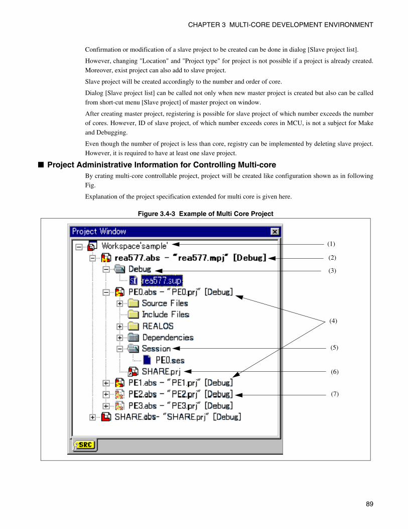
CHAPTER 3 MULTI-CORE DEVELOPMENT ENVIRONMENT
Confirmation or modification of a slave project to be created can be done in dialog [Slave project list].
However, changing "Location" and "Project type" for project is not possible if a project is already created.
Moreover, exist project can also add to slave project.
Slave project will be created accordingly to the number and order of core.
Dialog [Slave project list] can be called not only when new master project is created but also can be called
from short-cut menu [Slave project] of master project on window.
After creating master project, registering is possible for slave project of which number exceeds the number
of cores. However, ID of slave project, of which number exceeds cores in MCU, is not a subject for Make
and Debugging.
Even though the number of project is less than core, registry can be implemented by deleting slave project.
However, it is required to have at least one slave project.
■ Project Administrative Information for Controlling Multi-coreBy crating multi-core controllable project, project will be created like configuration shown as in following
Fig.
Explanation of the project specification extended for multi core is given here.
Figure 3.4-3 Example of Multi Core Project
(1)
(2)
(3)
(4)
(5)
(6)
(7)
89
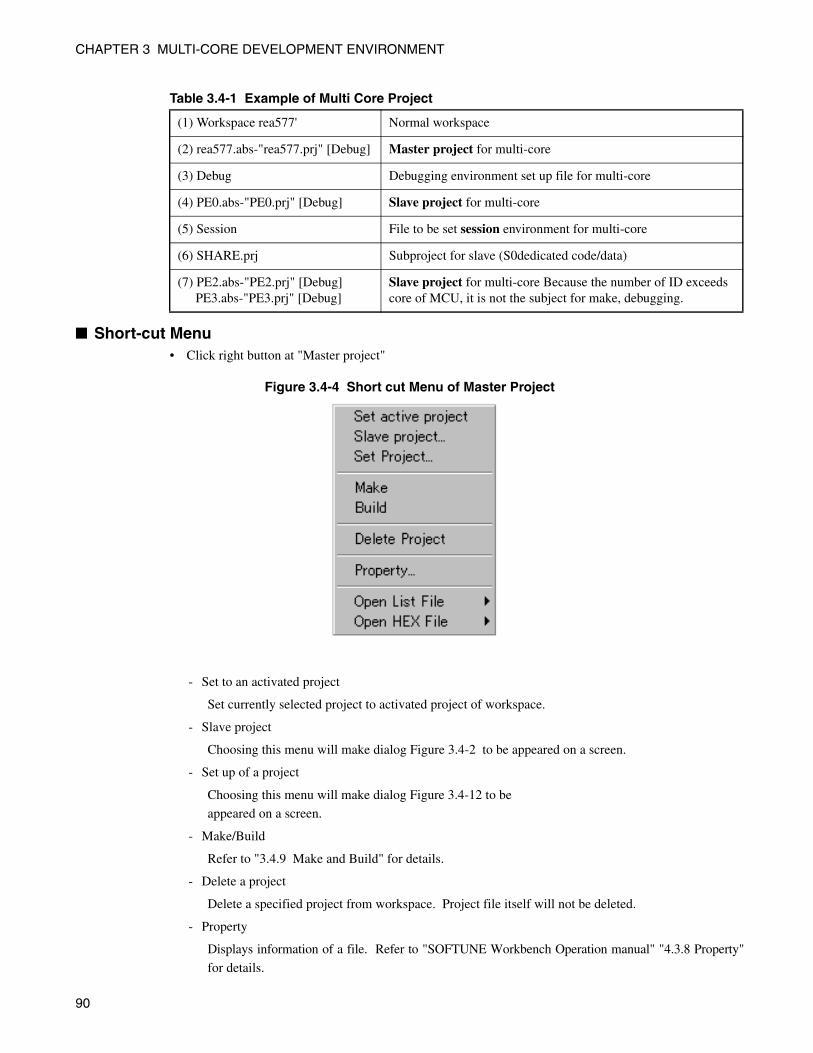
CHAPTER 3 MULTI-CORE DEVELOPMENT ENVIRONMENT
Table 3.4-1 Example of Multi Core Project
■ Short-cut Menu• Click right button at "Master project"
Figure 3.4-4 Short cut Menu of Master Project
- Set to an activated project
Set currently selected project to activated project of workspace.
- Slave project
Choosing this menu will make dialog Figure 3.4-2 to be appeared on a screen.
- Set up of a project
Choosing this menu will make dialog Figure 3.4-12 to be
appeared on a screen.
- Make/Build
Refer to "3.4.9 Make and Build" for details.
- Delete a project
Delete a specified project from workspace. Project file itself will not be deleted.
- Property
Displays information of a file. Refer to "SOFTUNE Workbench Operation manual" "4.3.8 Property"
for details.
(1) Workspace rea577' Normal workspace
(2) rea577.abs-"rea577.prj" [Debug] Master project for multi-core
(3) Debug Debugging environment set up file for multi-core
(4) PE0.abs-"PE0.prj" [Debug] Slave project for multi-core
(5) Session File to be set session environment for multi-core
(6) SHARE.prj Subproject for slave (S0dedicated code/data)
(7) PE2.abs-"PE2.prj" [Debug] PE3.abs-"PE3.prj" [Debug]
Slave project for multi-core Because the number of ID exceeds core of MCU, it is not the subject for make, debugging.
90
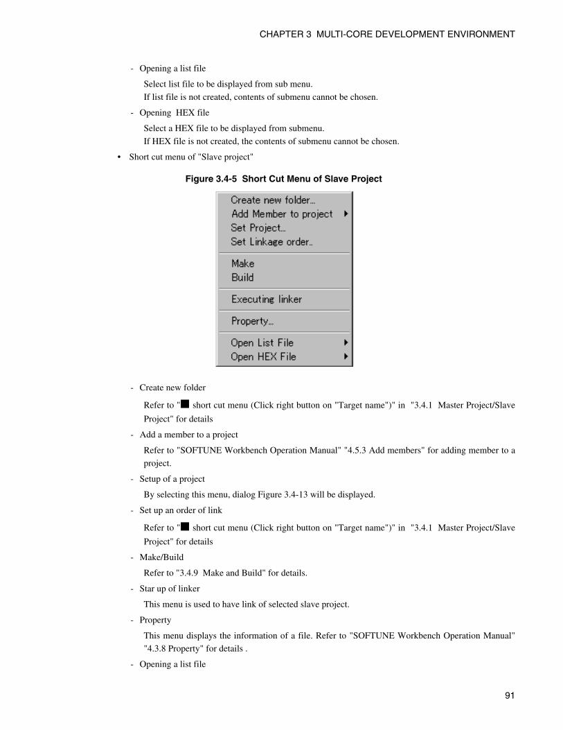
CHAPTER 3 MULTI-CORE DEVELOPMENT ENVIRONMENT
- Opening a list file
Select list file to be displayed from sub menu.
If list file is not created, contents of submenu cannot be chosen.
- Opening HEX file
Select a HEX file to be displayed from submenu.
If HEX file is not created, the contents of submenu cannot be chosen.
• Short cut menu of "Slave project"
Figure 3.4-5 Short Cut Menu of Slave Project
- Create new folder
Refer to "■ short cut menu (Click right button on "Target name")" in "3.4.1 Master Project/Slave
Project" for details
- Add a member to a project
Refer to "SOFTUNE Workbench Operation Manual" "4.5.3 Add members" for adding member to a
project.
- Setup of a project
By selecting this menu, dialog Figure 3.4-13 will be displayed.
- Set up an order of link
Refer to "■ short cut menu (Click right button on "Target name")" in "3.4.1 Master Project/Slave
Project" for details
- Make/Build
Refer to "3.4.9 Make and Build" for details.
- Star up of linker
This menu is used to have link of selected slave project.
- Property
This menu displays the information of a file. Refer to "SOFTUNE Workbench Operation Manual"
"4.3.8 Property" for details .
- Opening a list file
91
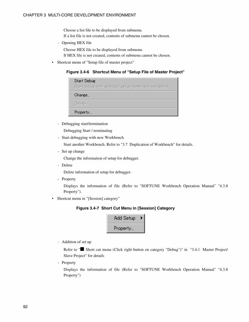
CHAPTER 3 MULTI-CORE DEVELOPMENT ENVIRONMENT
Choose a list file to be displayed from submenu.
If a list file is not created, contents of submenu cannot be chosen.
- Opening HEX file
Choose HEX file to be displayed from submenu.
If HEX file is not created, contents of submenu cannot be chosen.
• Shortcut menu of "Setup file of master project"
Figure 3.4-6 Shortcut Menu of "Setup File of Master Project"
- Debugging start/termination
Debugging Start / terminating
- Start debugging with new Workbench
Start another Workbench. Refer to "3.7 Duplication of Workbench" for details.
- Set up change
Change the information of setup for debugger.
- Delete
Delete information of setup for debugger.
- Property
Displays the information of file (Refer to "SOFTUNE Workbench Operation Manual" "4.3.8
Property").
• Shortcut menu in "[Session] category"
Figure 3.4-7 Short Cut Menu in [Session] Category
- Addition of set up
Refer to "■ Short cut menu (Click right button on category "Debug")" in "3.4.1 Master Project/
Slave Project" for details
- Property
Displays the information of file (Refer to "SOFTUNE Workbench Operation Manual" "4.3.8
Property")
92
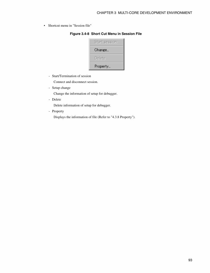
CHAPTER 3 MULTI-CORE DEVELOPMENT ENVIRONMENT
• Shortcut menu in "Session file"
Figure 3.4-8 Short Cut Menu in Session File
- Start/Termination of session
Connect and disconnect session.
- Setup change
Change the information of setup for debugger.
- Delete
Delete information of setup for debugger.
- Property
Displays the information of file (Refer to "4.3.8 Property").
93
CHAPTER 3 MULTI-CORE DEVELOPMENT ENVIRONMENT
3.4.1 Master Project/Slave Project
This section explains about master project and slave project.
Master project controls the set up for allocating each slave project, ABS combining tool option, slave
project and debugger.
In addition, target program will combine programs for each core and controls combined ABS files.
Slave project will be created accordingly to the number of core when master project is created (Be able to
change).
Slave project controls source, include file, and options for each core.
Target file controls ABS file for each core unit.
It is possible to connect session from slave project.
94
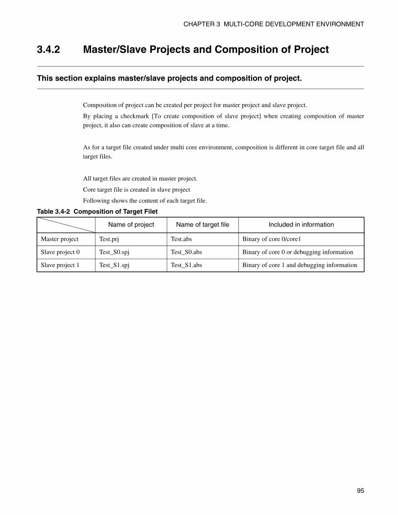
CHAPTER 3 MULTI-CORE DEVELOPMENT ENVIRONMENT
3.4.2 Master/Slave Projects and Composition of Project
This section explains master/slave projects and composition of project.
Composition of project can be created per project for master project and slave project.
By placing a checkmark [To create composition of slave project] when creating composition of master
project, it also can create composition of slave at a time.
As for a target file created under multi core environment, composition is different in core target file and all
target files.
All target files are created in master project.
Core target file is created in slave project
Following shows the content of each target file.
Table 3.4-2 Composition of Target Filet
Name of project Name of target file Included in information
Master project Test.prj Test.abs Binary of core 0/core1
Slave project 0 Test_S0.spj Test_S0.abs Binary of core 0 or debugging information
Slave project 1 Test_S1.spj Test_S1.abs Binary of core 1 and debugging information
95
CHAPTER 3 MULTI-CORE DEVELOPMENT ENVIRONMENT
3.4.3 Sub Project of Master/Slave Projects
This section explains the subproject for master/slave project.
Sub project, which is set to slave, only uses that slave as an object.
When sub project is set to master project in setup dialog "Dependence" , the same sub project as master
project are set for all slave projects.
Master project and slave project cannot be set as sub project for other project.
96
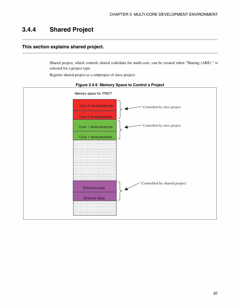
CHAPTER 3 MULTI-CORE DEVELOPMENT ENVIRONMENT
3.4.4 Shared Project
This section explains shared project.
Shared project, which controls shared code/data for multi-core, can be created when "Sharing (ABS) " is
selected for a project type.
Register shared project as a subproject of slave project.
Figure 3.4-9 Memory Space to Control a Project
Core 0 dedicated code
Core 0 dedicated data
Core 1 dedicated code
Core 1 dedicated data
Shared code
Shared data
Memory space for FR577
Controlled by shared project
Controlled by slave project
Controlled by slave project
97
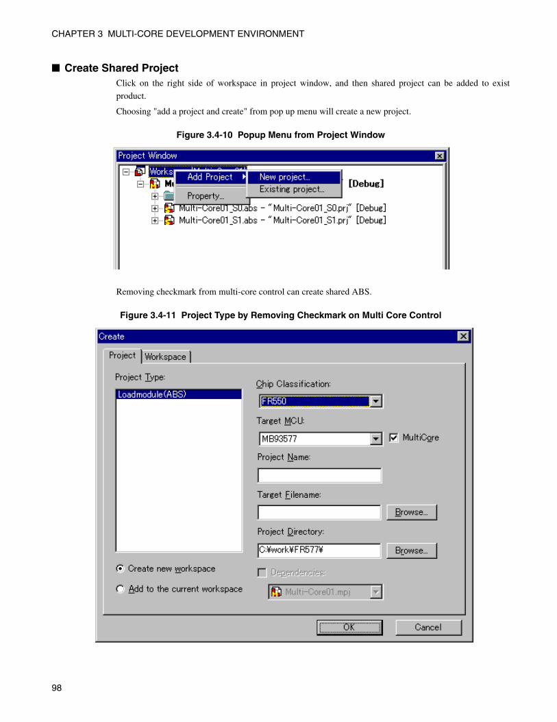
CHAPTER 3 MULTI-CORE DEVELOPMENT ENVIRONMENT
■ Create Shared ProjectClick on the right side of workspace in project window, and then shared project can be added to exist
product.
Choosing "add a project and create" from pop up menu will create a new project.
Figure 3.4-10 Popup Menu from Project Window
Removing checkmark from multi-core control can create shared ABS.
Figure 3.4-11 Project Type by Removing Checkmark on Multi Core Control
98
CHAPTER 3 MULTI-CORE DEVELOPMENT ENVIRONMENT
■ CautionsThere are some cautions need to be considered for shared project as follows.
• Do not make link to library
• Do not use following description in C language
float Arithmetic
long long Arithmetic
Assignment of substitute and arugument passing
• Do not use C++ file
• Write the names of assembler file and section with following style.
_SHARED_Project name_Configuration name_Section name
Ex: _SHARED_sample_debug_CODE
99
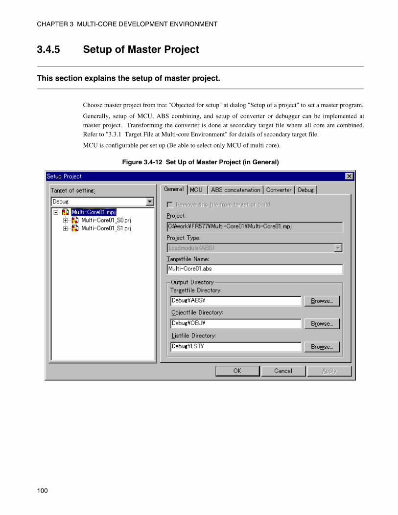
CHAPTER 3 MULTI-CORE DEVELOPMENT ENVIRONMENT
3.4.5 Setup of Master Project
This section explains the setup of master project.
Choose master project from tree "Objected for setup" at dialog "Setup of a project" to set a master program.
Generally, setup of MCU, ABS combining, and setup of converter or debugger can be implemented at
master project. Transforming the converter is done at secondary target file where all core are combined.
Refer to "3.3.1 Target File at Multi-core Environment" for details of secondary target file.
MCU is configurable per set up (Be able to select only MCU of multi core).
Figure 3.4-12 Set Up of Master Project (in General)
100
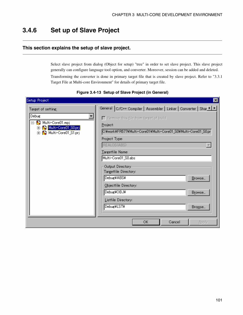
CHAPTER 3 MULTI-CORE DEVELOPMENT ENVIRONMENT
3.4.6 Set up of Slave Project
This section explains the setup of slave project.
Select slave project from dialog (Object for setup) "tree" in order to set slave project. This slave project
generally can configure language tool option, and converter. Moreover, session can be added and deleted.
Transforming the converter is done in primary target file that is created by slave project. Refer to "3.3.1
Target File at Multi-core Environment" for details of primary target file.
Figure 3.4-13 Setup of Slave Project (in General)
101
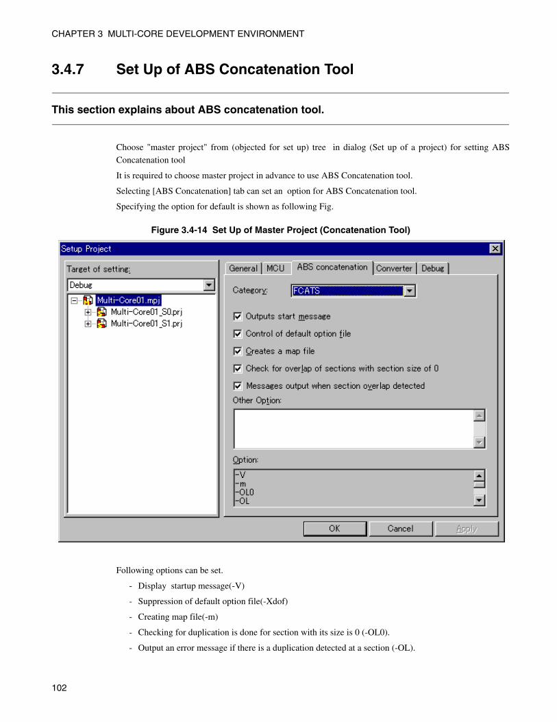
CHAPTER 3 MULTI-CORE DEVELOPMENT ENVIRONMENT
3.4.7 Set Up of ABS Concatenation Tool
This section explains about ABS concatenation tool.
Choose "master project" from (objected for set up) tree in dialog (Set up of a project) for setting ABS
Concatenation tool
It is required to choose master project in advance to use ABS Concatenation tool.
Selecting [ABS Concatenation] tab can set an option for ABS Concatenation tool.
Specifying the option for default is shown as following Fig.
Figure 3.4-14 Set Up of Master Project (Concatenation Tool)
Following options can be set.
- Display startup message(-V)
- Suppression of default option file(-Xdof)
- Creating map file(-m)
- Checking for duplication is done for section with its size is 0 (-OL0).
- Output an error message if there is a duplication detected at a section (-OL).
102
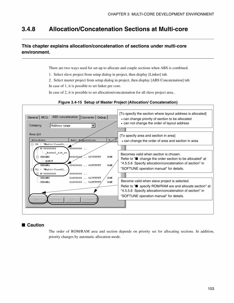
CHAPTER 3 MULTI-CORE DEVELOPMENT ENVIRONMENT
3.4.8 Allocation/Concatenation Sections at Multi-core
This chapter explains allocation/concatenation of sections under multi-core environment.
There are two ways used for set-up to allocate and couple sections when ABS is combined.
1. Select slave project from setup dialog in project, then display [Linker] tab.
2. Select master project from setup dialog in project, then display [ABS Concatenation] tab.
In case of 1, it is possible to set linker per core.
In case of 2, it is possible to set allocation/concatenation for all slave project area..
Figure 3.4-15 Setup of Master Project (Allocation/ Concatenation)
■ CautionThe order of ROM/RAM area and section depends on priority set for allocating sections. In addition,
priority changes by automatic allocation mode.
[To specify the section where layout address is allocated]
• can change priority of section to be allocated• can not change the order of layout address
[To specify area and section in area]
• can change the order of area and section in area
Becomes valid when section is chosen.Refer to "■ change the order section to be allocated" at "4.5.5.6 Specify allocation/concatenation of section" in
"SOFTUNE operation manual" for details.
Refer to "■ specify ROM/RAM are and allocate section" at"4.5.5.6 Specify allocation/concatenation of section" in
"SOFTUNE operation manual" for details.
Become valid when slave project is selected.
103
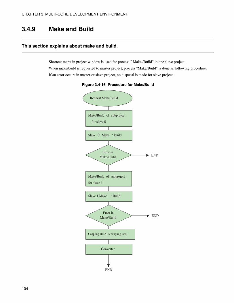
CHAPTER 3 MULTI-CORE DEVELOPMENT ENVIRONMENT
3.4.9 Make and Build
This section explains about make and build.
Shortcut menu in project window is used for process " Make /Build" in one slave project.
When make/build is requested to master project, process "Make/Build" is done as following procedure.
If an error occurs in master or slave project, no disposal is made for slave project.
Figure 3.4-16 Procedure for Make/Build
Slave Make Build
Slave 1 Make Build
Coupling all (ABS coupling tool)
Error in Make/Build END
Converter
Make/Build of subproject
for slave 0
Make/Build of subproject
for slave 1
Make/Build END
Request Make/Build
Error in
END
104
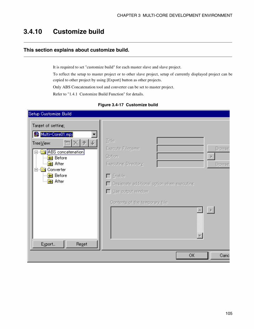
CHAPTER 3 MULTI-CORE DEVELOPMENT ENVIRONMENT
3.4.10 Customize build
This section explains about customize build.
It is required to set "customize build" for each master slave and slave project.
To reflect the setup to master project or to other slave project, setup of currently displayed project can be
copied to other project by using [Export] button as other projects.
Only ABS Concatenation tool and converter can be set to master project.
Refer to "1.4.1 Customize Build Function" for details.
Figure 3.4-17 Customize build
105
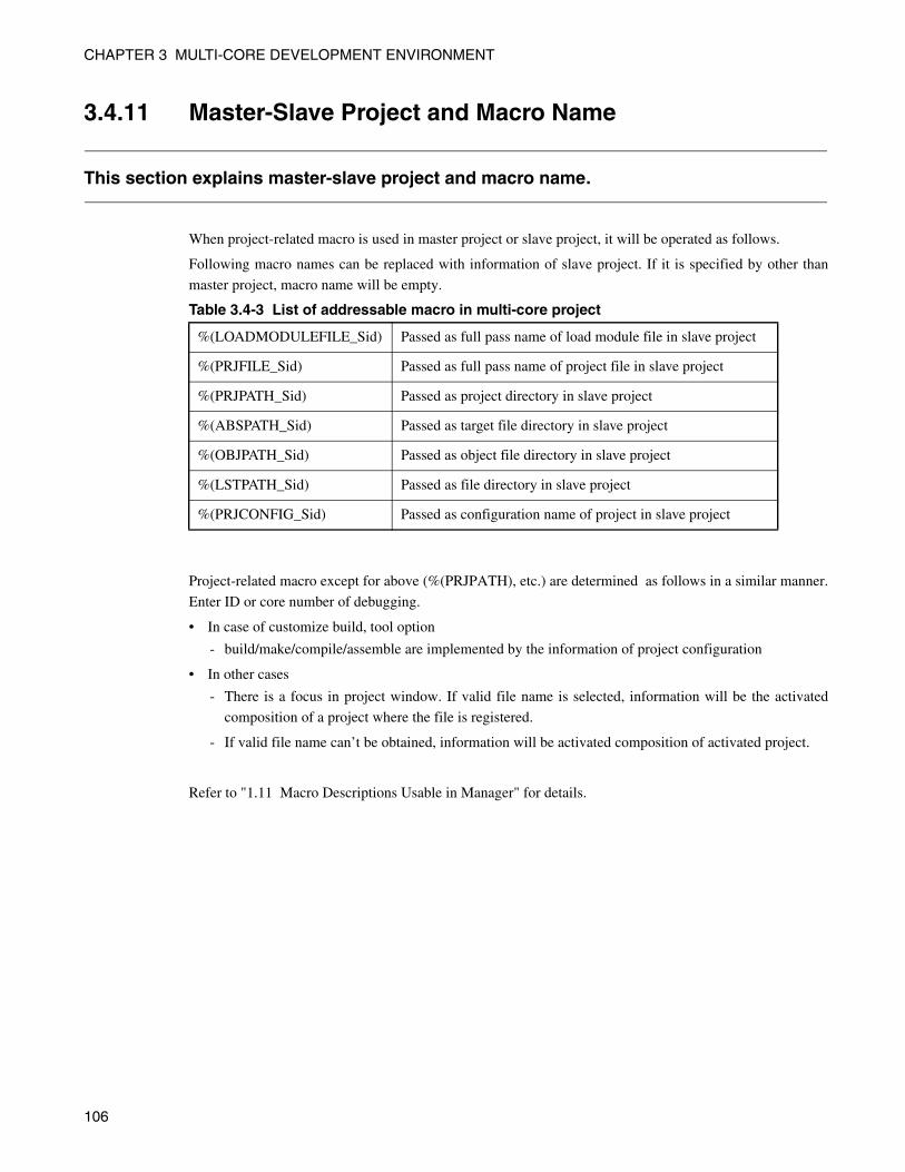
CHAPTER 3 MULTI-CORE DEVELOPMENT ENVIRONMENT
3.4.11 Master-Slave Project and Macro Name
This section explains master-slave project and macro name.
When project-related macro is used in master project or slave project, it will be operated as follows.
Following macro names can be replaced with information of slave project. If it is specified by other than
master project, macro name will be empty.
Table 3.4-3 List of addressable macro in multi-core project
Project-related macro except for above (%(PRJPATH), etc.) are determined as follows in a similar manner.
Enter ID or core number of debugging.
• In case of customize build, tool option
- build/make/compile/assemble are implemented by the information of project configuration
• In other cases
- There is a focus in project window. If valid file name is selected, information will be the activated
composition of a project where the file is registered.
- If valid file name can’t be obtained, information will be activated composition of activated project.
Refer to "1.11 Macro Descriptions Usable in Manager" for details.
%(LOADMODULEFILE_Sid) Passed as full pass name of load module file in slave project
%(PRJFILE_Sid) Passed as full pass name of project file in slave project
%(PRJPATH_Sid) Passed as project directory in slave project
%(ABSPATH_Sid) Passed as target file directory in slave project
%(OBJPATH_Sid) Passed as object file directory in slave project
%(LSTPATH_Sid) Passed as file directory in slave project
%(PRJCONFIG_Sid) Passed as configuration name of project in slave project
106
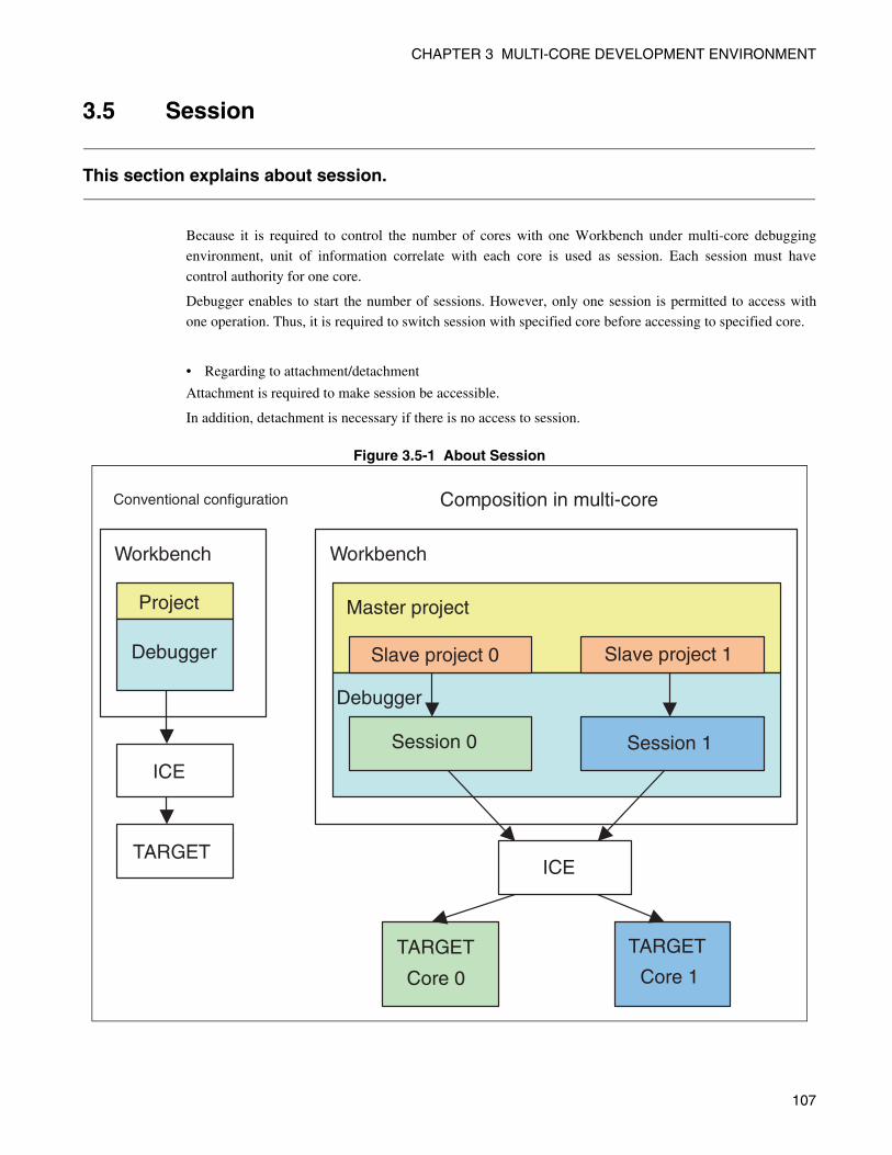
CHAPTER 3 MULTI-CORE DEVELOPMENT ENVIRONMENT
3.5 Session
This section explains about session.
Because it is required to control the number of cores with one Workbench under multi-core debugging
environment, unit of information correlate with each core is used as session. Each session must have
control authority for one core.
Debugger enables to start the number of sessions. However, only one session is permitted to access with
one operation. Thus, it is required to switch session with specified core before accessing to specified core.
• Regarding to attachment/detachment
Attachment is required to make session be accessible.
In addition, detachment is necessary if there is no access to session.
Figure 3.5-1 About Session
Conventional configuration
Workbench
Master project
Debugger
Session 1Session 0
Workbench
ICE
TARGETICE
TARGET
Core 0
TARGET
Core 1
Debugger Slave project 0
Composition in multi-core
Project
Slave project 1
107
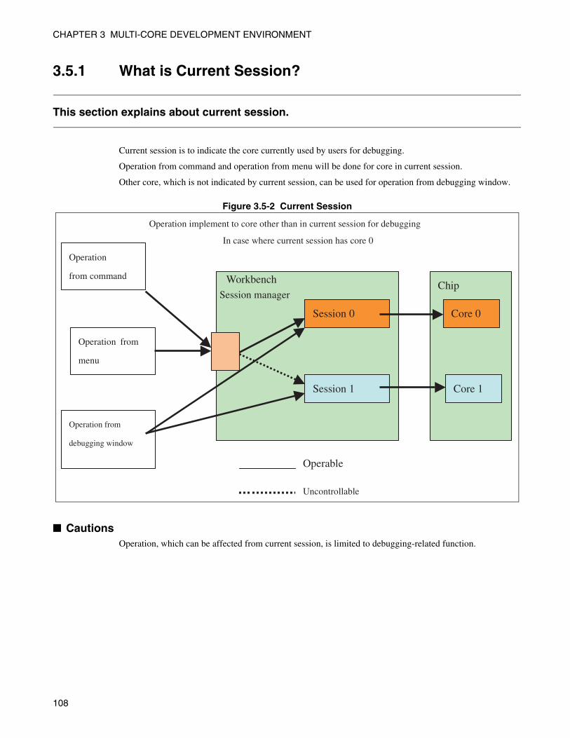
CHAPTER 3 MULTI-CORE DEVELOPMENT ENVIRONMENT
3.5.1 What is Current Session?
This section explains about current session.
Current session is to indicate the core currently used by users for debugging.
Operation from command and operation from menu will be done for core in current session.
Other core, which is not indicated by current session, can be used for operation from debugging window.
Figure 3.5-2 Current Session
■ CautionsOperation, which can be affected from current session, is limited to debugging-related function.
Workbench
Operation
from command
Operation implement to core other than in current session for debugging
In case where current session has core 0
Operation from
menu
Operation from
debugging window
Session manager
Session 0
Session 1
Chip
Core 0
Core 1
Operable
Uncontrollable
108
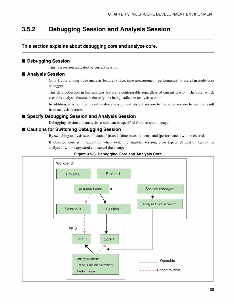
CHAPTER 3 MULTI-CORE DEVELOPMENT ENVIRONMENT
3.5.2 Debugging Session and Analysis Session
This section explains about debugging core and analyze core.
■ Debugging SessionThis is a session indicated by current session.
■ Analysis SessionOnly 1 core among three analysis features (trace, time measurement, performance) is useful in multi-core
debugger.
This data collection in this analysis feature is configurable regardless of current session. The core, which
uses this analysis feature, is the only one being called an analysis session.
In addition, it is required to set analysis session and current session to the same session to see the result
from analysis features.
■ Specify Debugging Session and Analysis SessionDebugging session and analysis session can be specified from session manager.
■ Cautions for Switching Debugging SessionBy switching analysis session, data of [trace], [time measurement], and [performance] will be cleared.
If objected core is in execution when switching analysis session, error [specified session cannot be
analyzed] will be appeared and cancel the change.
Figure 3.5-3 Debugging Core and Analysis Core
FR-V
Core 0 Core 1
Analysis function
Trace, Time measurement,
Performance
Workbench
Project 0 Project 1
Session 0 Session 1 Analysis function control
Session manager Debugging control
Operable
Uncontrollable
109
CHAPTER 3 MULTI-CORE DEVELOPMENT ENVIRONMENT
3.6 Debugging Multi-core
This section explains about debugging function specialized for multi-core.
Following items are explained for debugging function of multi-core.
• Start up of debugger
• Start up of session
• Menu, Toolbar
• Debugging window
• Loading target file
• Software break
• Analysis function
110
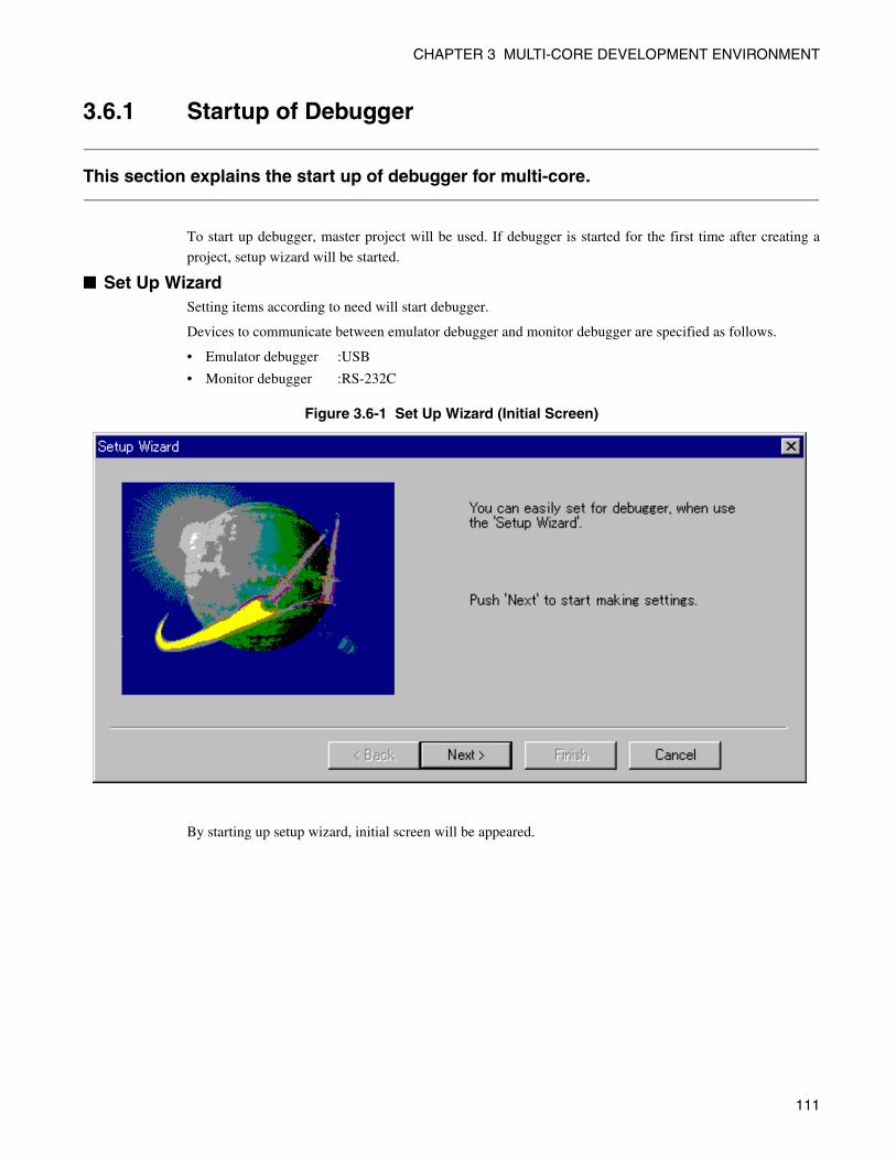
CHAPTER 3 MULTI-CORE DEVELOPMENT ENVIRONMENT
3.6.1 Startup of Debugger
This section explains the start up of debugger for multi-core.
To start up debugger, master project will be used. If debugger is started for the first time after creating a
project, setup wizard will be started.
■ Set Up WizardSetting items according to need will start debugger.
Devices to communicate between emulator debugger and monitor debugger are specified as follows.
• Emulator debugger :USB
• Monitor debugger :RS-232C
Figure 3.6-1 Set Up Wizard (Initial Screen)
By starting up setup wizard, initial screen will be appeared.
111
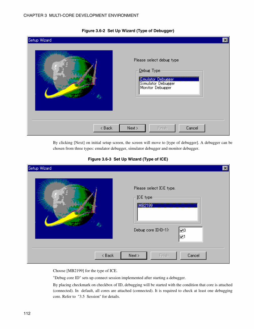
CHAPTER 3 MULTI-CORE DEVELOPMENT ENVIRONMENT
Figure 3.6-2 Set Up Wizard (Type of Debugger)
By clicking [Next] on initial setup screen, the screen will move to [type of debugger]. A debugger can be
chosen from three types: emulator debugger, simulator debugger and monitor debugger.
Figure 3.6-3 Set Up Wizard (Type of ICE)
Choose [MB2199] for the type of ICE.
"Debug core ID" sets up connect session implemented after starting a debugger.
By placing checkmark on checkbox of ID, debugging will be started with the condition that core is attached
(connected). In default, all cores are attached (connected). It is required to check at least one debugging
core. Refer to "3.5 Session" for details.
112
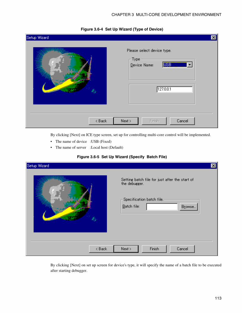
CHAPTER 3 MULTI-CORE DEVELOPMENT ENVIRONMENT
Figure 3.6-4 Set Up Wizard (Type of Device)
By clicking [Next] on ICE type screen, set up for controlling multi-core control will be implemented.
• The name of device :USB (Fixed)
• The name of server :Local host (Default)
Figure 3.6-5 Set Up Wizard (Specify Batch File)
By clicking [Next] on set up screen for device's type, it will specify the name of a batch file to be executed
after starting debugger.
113
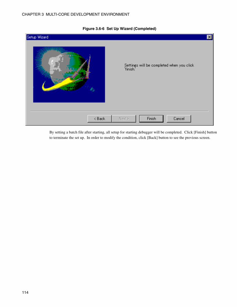
CHAPTER 3 MULTI-CORE DEVELOPMENT ENVIRONMENT
Figure 3.6-6 Set Up Wizard (Completed)
By setting a batch file after starting, all setup for starting debugger will be completed. Click [Finish] button
to terminate the set up. In order to modify the condition, click [Back] button to see the previous screen.
114
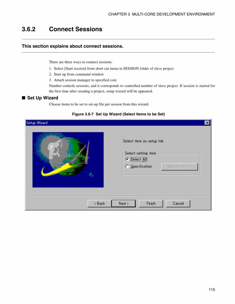
CHAPTER 3 MULTI-CORE DEVELOPMENT ENVIRONMENT
3.6.2 Connect Sessions
This section explains about connect sessions.
There are three ways to connect sessions.
1. Select [Start session] from short cut menu in SESSION folder of slave project
2. Start up from command window
3. Attach session manager to specified core
Number controls sessions, and it corresponds to controlled number of slave project. If session is started for
the first time after creating a project, setup wizard will be appeared.
■ Set Up WizardChoose items to be set to set-up file per session from this wizard.
Figure 3.6-7 Set Up Wizard (Select Items to be Set)
115
CHAPTER 3 MULTI-CORE DEVELOPMENT ENVIRONMENT
3.6.3 Menu or Toolbar
This section explains about menu or toolbar.
In case where debugging function needs to be called from menu or toolbar, it means that operation will be
implemented for current session.
Refer to session manager or session tool bar for current status of session.
Refer to "3.5 Session" for details
If debugging core is done in different session, switch session by using session manager or session toolbar.
116
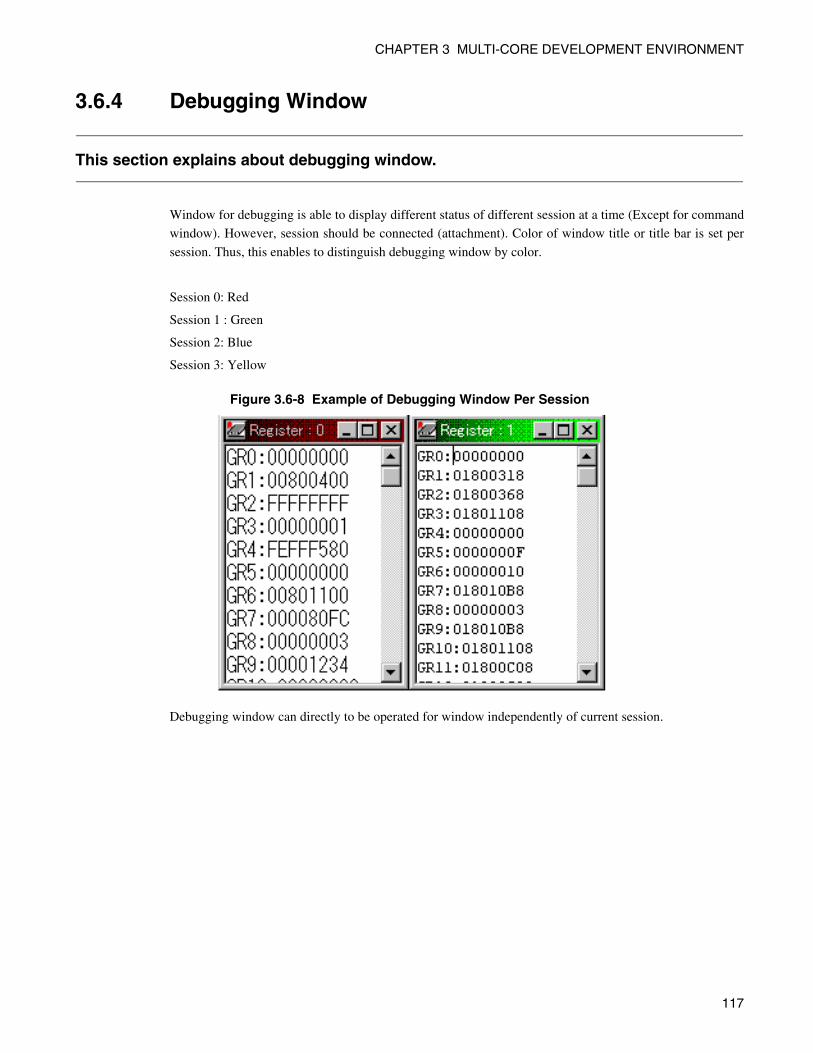
CHAPTER 3 MULTI-CORE DEVELOPMENT ENVIRONMENT
3.6.4 Debugging Window
This section explains about debugging window.
Window for debugging is able to display different status of different session at a time (Except for command
window). However, session should be connected (attachment). Color of window title or title bar is set per
session. Thus, this enables to distinguish debugging window by color.
Session 0: Red
Session 1 : Green
Session 2: Blue
Session 3: Yellow
Figure 3.6-8 Example of Debugging Window Per Session
Debugging window can directly to be operated for window independently of current session.
117
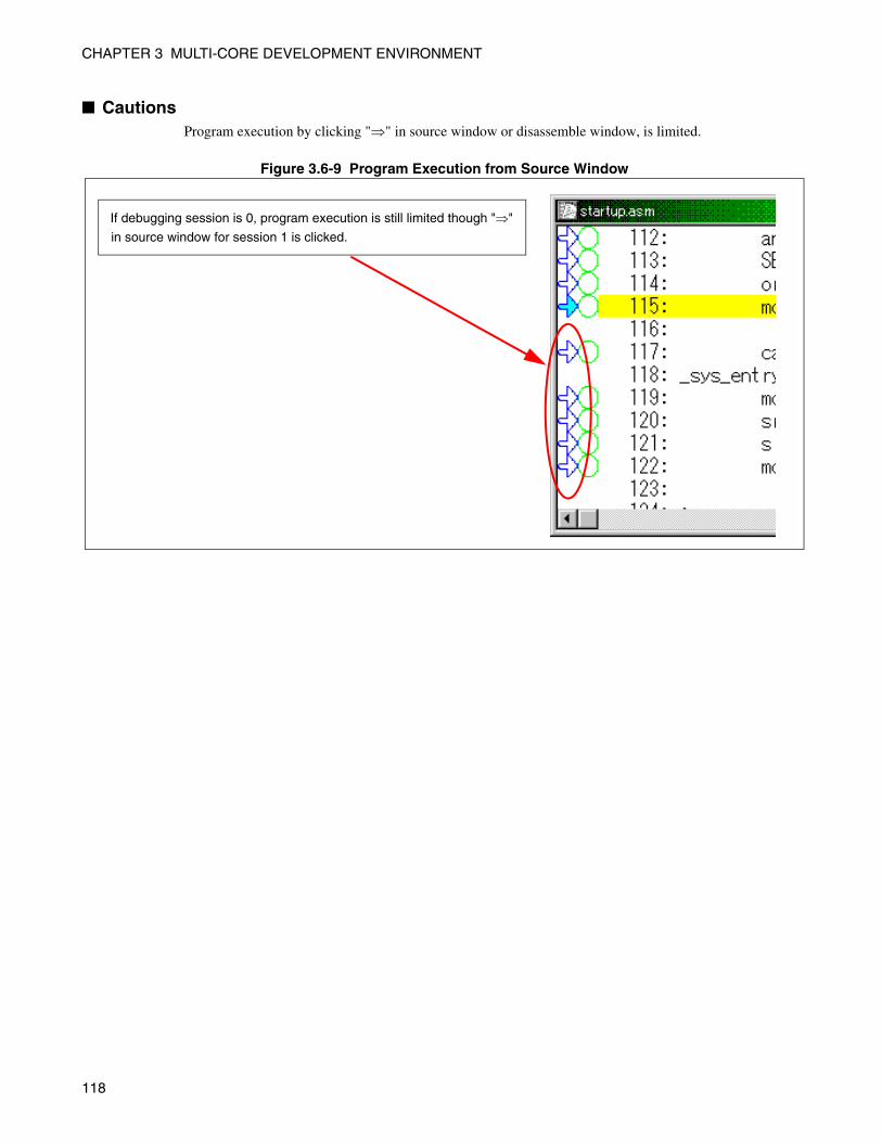
CHAPTER 3 MULTI-CORE DEVELOPMENT ENVIRONMENT
■ CautionsProgram execution by clicking "⇒" in source window or disassemble window, is limited.
Figure 3.6-9 Program Execution from Source Window
If debugging session is 0, program execution is still limited though "⇒"
in source window for session 1 is clicked.
118
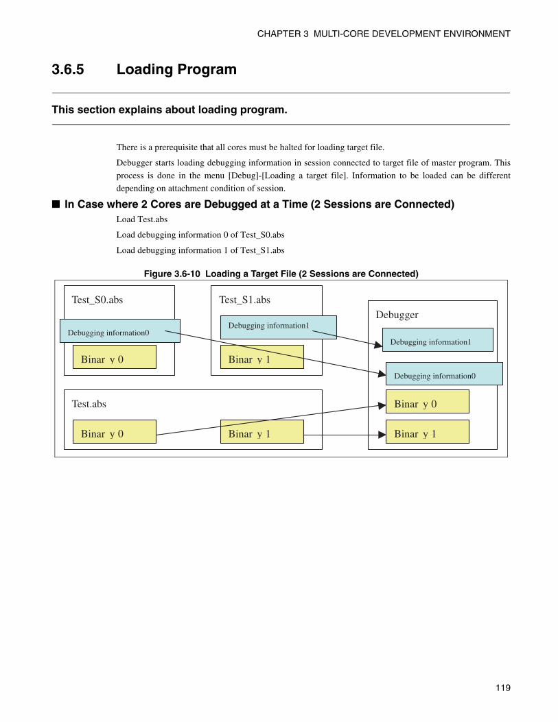
CHAPTER 3 MULTI-CORE DEVELOPMENT ENVIRONMENT
3.6.5 Loading Program
This section explains about loading program.
There is a prerequisite that all cores must be halted for loading target file.
Debugger starts loading debugging information in session connected to target file of master program. This
process is done in the menu [Debug]-[Loading a target file]. Information to be loaded can be different
depending on attachment condition of session.
■ In Case where 2 Cores are Debugged at a Time (2 Sessions are Connected)Load Test.abs
Load debugging information 0 of Test_S0.abs
Load debugging information 1 of Test_S1.abs
Figure 3.6-10 Loading a Target File (2 Sessions are Connected)
Test_S0.abs
Debugging information0
Binar y 0
Test_S1.abs
Debugging information1
Binar y 1
Test.abs
Binar y 0 Binar y 1
Debugger
Binar y 1
Binar y 0
Debugging information1
Debugging information0
119
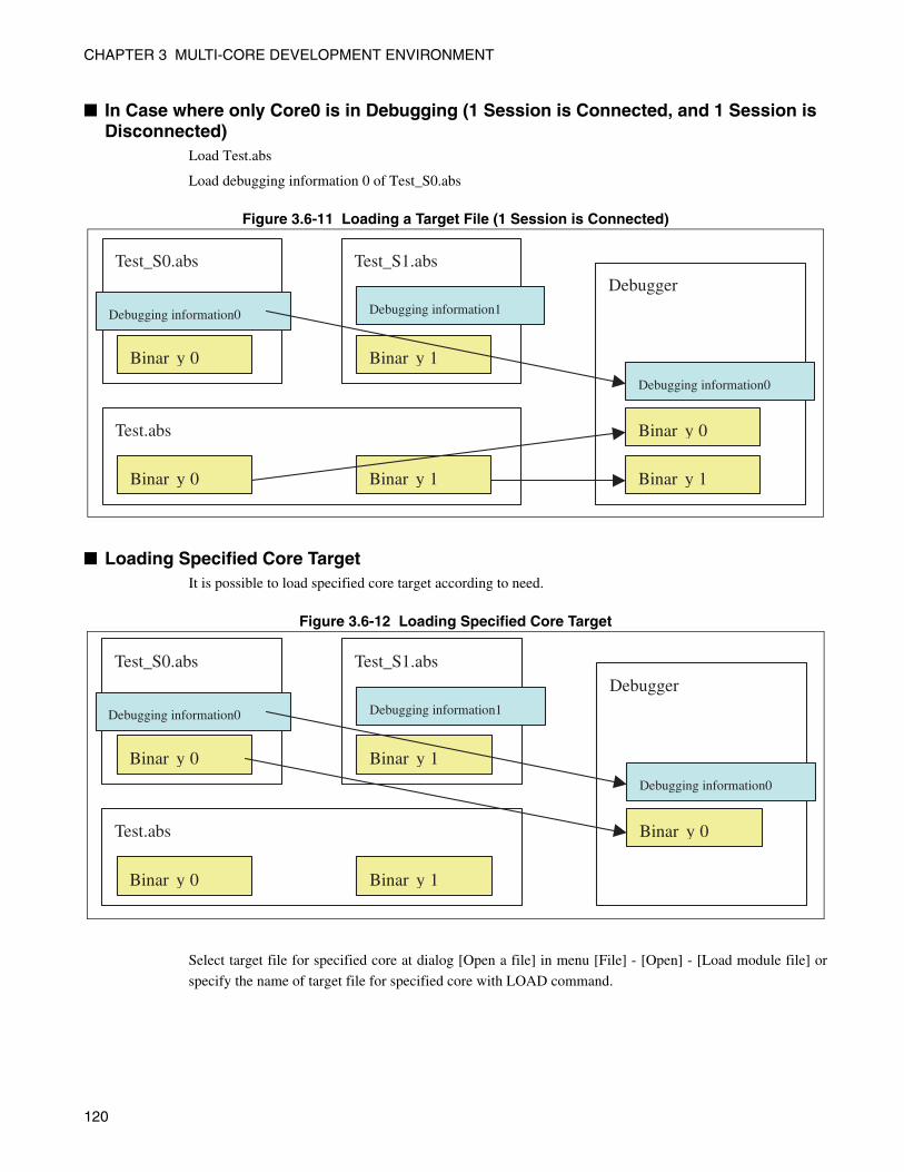
CHAPTER 3 MULTI-CORE DEVELOPMENT ENVIRONMENT
■ In Case where only Core0 is in Debugging (1 Session is Connected, and 1 Session is Disconnected)
Load Test.abs
Load debugging information 0 of Test_S0.abs
Figure 3.6-11 Loading a Target File (1 Session is Connected)
■ Loading Specified Core TargetIt is possible to load specified core target according to need.
Figure 3.6-12 Loading Specified Core Target
Select target file for specified core at dialog [Open a file] in menu [File] - [Open] - [Load module file] or
specify the name of target file for specified core with LOAD command.
Test_S0.abs
Debugging information0
Binar y 0
Test_S1.abs
Debugging information1
Binar y 1
Test.abs
Binar y 0 Binar y 1
Debugger
Binar y 1
Binar y 0
Debugging information0
Test_S0.abs
Debugging information0
Binar y 0
Test_S1.abs
Debugging information1
Binar y 1
Test.abs
Binar y 0 Binar y 1
Debugger
Binar y 0
Debugging information0
120
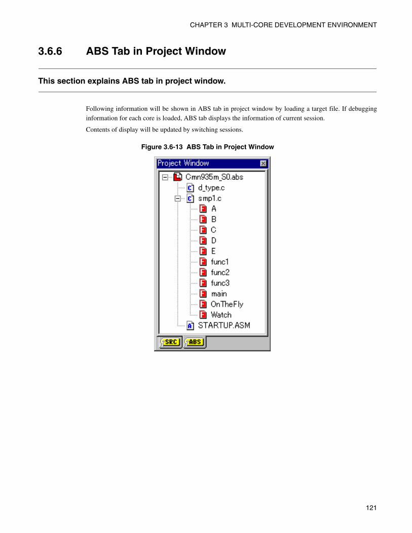
CHAPTER 3 MULTI-CORE DEVELOPMENT ENVIRONMENT
3.6.6 ABS Tab in Project Window
This section explains ABS tab in project window.
Following information will be shown in ABS tab in project window by loading a target file. If debugging
information for each core is loaded, ABS tab displays the information of current session.
Contents of display will be updated by switching sessions.
Figure 3.6-13 ABS Tab in Project Window
121
CHAPTER 3 MULTI-CORE DEVELOPMENT ENVIRONMENT
3.6.7 Break
This section explains about software break and hardware break.
• Software break
Software break is limited to 4096 points for all cores. Thus, addressable points in one core are 4096/the
number of core.
If there are 2 cores, software break can be addressed till 2048 pcs for 1 core.
• Hardware break
The number to be set to hardware break is determined by core for multi-core debugger.
■ CautionsIf software break is set to shared code, it will be halted independent of core 0 or core 1.
122
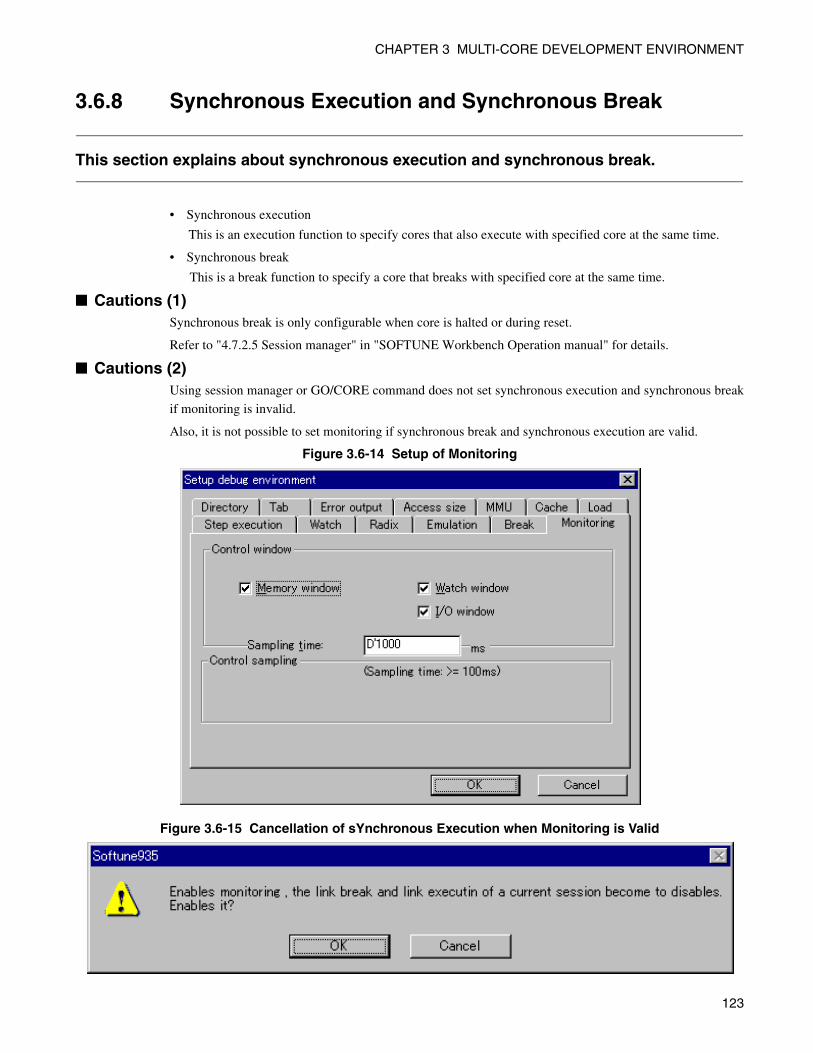
CHAPTER 3 MULTI-CORE DEVELOPMENT ENVIRONMENT
3.6.8 Synchronous Execution and Synchronous Break
This section explains about synchronous execution and synchronous break.
• Synchronous execution
This is an execution function to specify cores that also execute with specified core at the same time.
• Synchronous break
This is a break function to specify a core that breaks with specified core at the same time.
■ Cautions (1)Synchronous break is only configurable when core is halted or during reset.
Refer to "4.7.2.5 Session manager" in "SOFTUNE Workbench Operation manual" for details.
■ Cautions (2)Using session manager or GO/CORE command does not set synchronous execution and synchronous break
if monitoring is invalid.
Also, it is not possible to set monitoring if synchronous break and synchronous execution are valid.
Figure 3.6-14 Setup of Monitoring
Figure 3.6-15 Cancellation of sYnchronous Execution when Monitoring is Valid
123
CHAPTER 3 MULTI-CORE DEVELOPMENT ENVIRONMENT
3.6.9 Analysis Feature
This section explains about analysis feature.
It is required to choose core to be used for analysis in multi-core debugger in advance. Other core cannot be
used for analysis. Following features are equipped for analysis feature.
- Trace
- Time measurement
- Performance
Even though trace window is opened in session where analysis feature is invalid, contents will not be
displayed.
Refer to "3.5.2 Debugging Session and Analysis Session" for details.
124
CHAPTER 3 MULTI-CORE DEVELOPMENT ENVIRONMENT
3.7 Duplication of Workbench
This section explains about start up the method to control the number of Workbench with duplicated Workbench.
It is possible to start another Workbench from currently used Workbench. Duplicated Workbench shares
the same project with other.
In this instruction manual, originally working Workbench is called Original Workbench and duplicated
Workbench is called as Duplicated Workbench.
• Start duplicating
• Terminate duplication
• Start/terminating debugging
• Creating target program
• Downloading a program
125
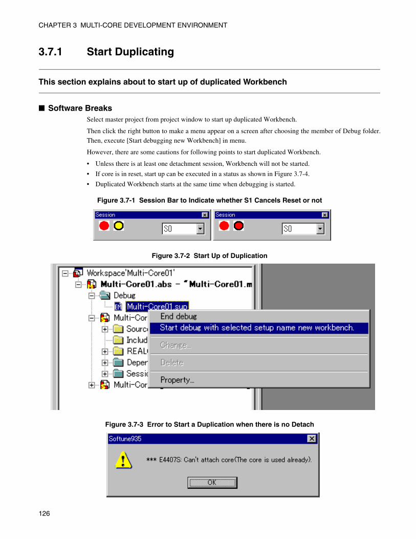
CHAPTER 3 MULTI-CORE DEVELOPMENT ENVIRONMENT
3.7.1 Start Duplicating
This section explains about to start up of duplicated Workbench
■ Software Breaks Select master project from project window to start up duplicated Workbench.
Then click the right button to make a menu appear on a screen after choosing the member of Debug folder.
Then, execute [Start debugging new Workbench] in menu.
However, there are some cautions for following points to start duplicated Workbench.
• Unless there is at least one detachment session, Workbench will not be started.
• If core is in reset, start up can be executed in a status as shown in Figure 3.7-4.
• Duplicated Workbench starts at the same time when debugging is started.
Figure 3.7-1 Session Bar to Indicate whether S1 Cancels Reset or not
Figure 3.7-2 Start Up of Duplication
Figure 3.7-3 Error to Start a Duplication when there is no Detach
126
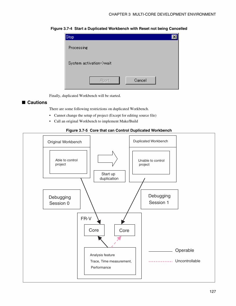
CHAPTER 3 MULTI-CORE DEVELOPMENT ENVIRONMENT
Figure 3.7-4 Start a Duplicated Workbench with Reset not being Cancelled
Finally, duplicated Workbench will be started.
■ CautionsThere are some following restrictions on duplicated Workbench.
• Cannot change the setup of project (Except for editing source file)
• Call an original Workbench to implement Make/Build
Figure 3.7-5 Core that can Control Duplicated Workbench
FR-V
Original Workbench
Able to control project
DebuggingSession 0
Core Core
Start upduplication
Duplicated Workbench
Unable to controlproject
Debugging
Session 1
Operable
Uncontrollable
Analysis feature
Trace, Time measurement,
Performance
127
CHAPTER 3 MULTI-CORE DEVELOPMENT ENVIRONMENT
3.7.2 Termination of Duplicated Workbench
This section explains about termination of duplicated Workbench.
By terminating to debug a duplicated Workbench, it also will stop a duplicated Workbench.
In order to stop an original Workbench, it is necessary to finish duplicated Workbench by force. Then
original Workbench will be terminated.
■ CautionsIf duplicated Workbench is in process, an original Workbench cannot be terminated.
Wait for a duplicated Workbench process to be completed, and then finish an original Workbench.
128
CHAPTER 3 MULTI-CORE DEVELOPMENT ENVIRONMENT
3.7.3 Creating and Loading Target File
This section explains the method for making and loading target file with duplicated Workbench.
• Create a target file
When creating a target file (Make/Build) in duplicated Workbench , no operation can be done at duplicatedWorkbench. Instead, target file will be created at an original Workbench.
• Loading a target file
It is possible to download a program from duplicated Workbench.
An original Workbench always does this operation.
129
CHAPTER 3 MULTI-CORE DEVELOPMENT ENVIRONMENT
3.8 Command
This section explains about command and intrinsic function.
Following explains command and intrinsic function added to multi-core debugger.
• Command
• Intrinsic function
130
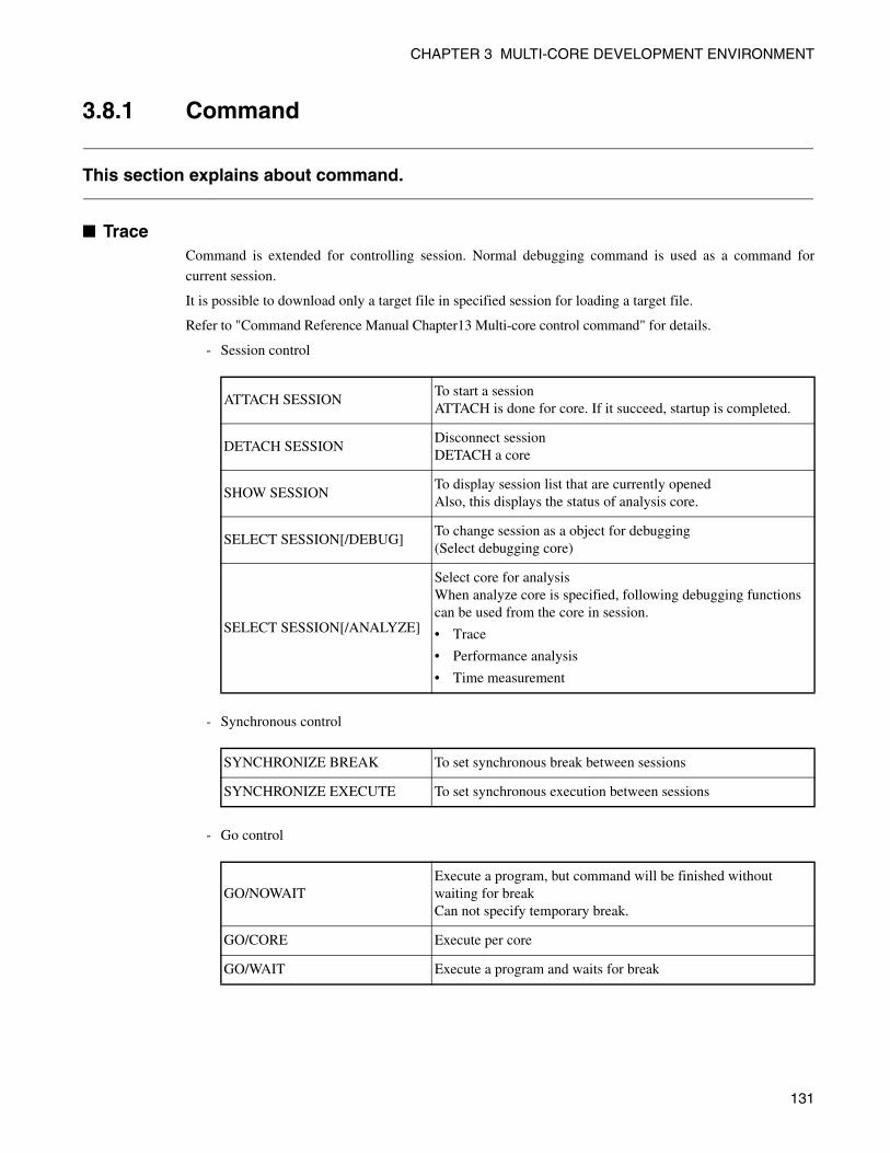
CHAPTER 3 MULTI-CORE DEVELOPMENT ENVIRONMENT
3.8.1 Command
This section explains about command.
■ Trace Command is extended for controlling session. Normal debugging command is used as a command for
current session.
It is possible to download only a target file in specified session for loading a target file.
Refer to "Command Reference Manual Chapter13 Multi-core control command" for details.
- Session control
- Synchronous control
- Go control
ATTACH SESSIONTo start a sessionATTACH is done for core. If it succeed, startup is completed.
DETACH SESSIONDisconnect sessionDETACH a core
SHOW SESSIONTo display session list that are currently openedAlso, this displays the status of analysis core.
SELECT SESSION[/DEBUG]To change session as a object for debugging(Select debugging core)
SELECT SESSION[/ANALYZE]
Select core for analysisWhen analyze core is specified, following debugging functions can be used from the core in session.
• Trace
• Performance analysis
• Time measurement
SYNCHRONIZE BREAK To set synchronous break between sessions
SYNCHRONIZE EXECUTE To set synchronous execution between sessions
GO/NOWAITExecute a program, but command will be finished without waiting for breakCan not specify temporary break.
GO/CORE Execute per core
GO/WAIT Execute a program and waits for break
131
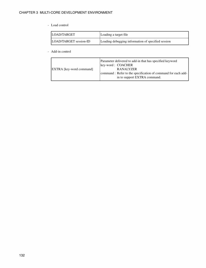
CHAPTER 3 MULTI-CORE DEVELOPMENT ENVIRONMENT
- Load control
- Add-in control
LOAD/TARGET Loading a target file
LOAD/TARGET session-ID Loading debugging information of specified session
EXTRA [key-word command]
Parameter delivered to add-in that has specified keywordkey-word : COACHER
RANALYZERcommand : Refer to the specification of command for each add-
in to support EXTRA command.
132
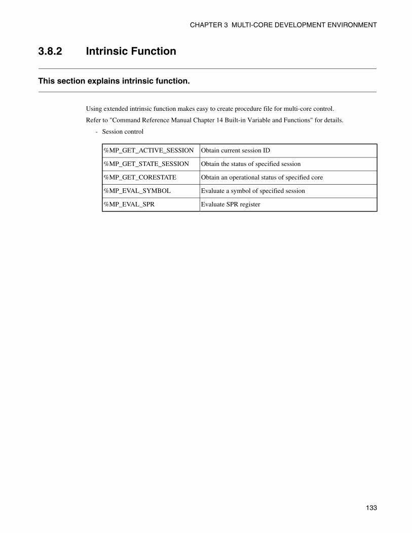
CHAPTER 3 MULTI-CORE DEVELOPMENT ENVIRONMENT
3.8.2 Intrinsic Function
This section explains intrinsic function.
Using extended intrinsic function makes easy to create procedure file for multi-core control.
Refer to "Command Reference Manual Chapter 14 Built-in Variable and Functions" for details.
- Session control
%MP_GET_ACTIVE_SESSION Obtain current session ID
%MP_GET_STATE_SESSION Obtain the status of specified session
%MP_GET_CORESTATE Obtain an operational status of specified core
%MP_EVAL_SYMBOL Evaluate a symbol of specified session
%MP_EVAL_SPR Evaluate SPR register
133
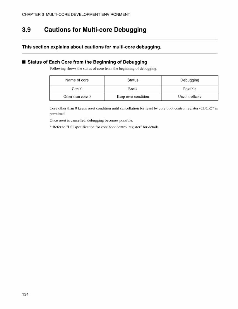
CHAPTER 3 MULTI-CORE DEVELOPMENT ENVIRONMENT
3.9 Cautions for Multi-core Debugging
This section explains about cautions for multi-core debugging.
■ Status of Each Core from the Beginning of DebuggingFollowing shows the status of core from the beginning of debugging.
Core other than 0 keeps reset condition until cancellation for reset by core boot control register (CBCR)* is
permitted.
Once reset is cancelled, debugging becomes possible.
*:Refer to "LSI specification for core boot control register" for details.
Name of core Status Debugging
Core 0 Break Possible
Other than core 0 Keep reset condition Uncontrollable
134

INDEX
INDEX
The index follows on the next page.This is listed in alphabetic order.
135
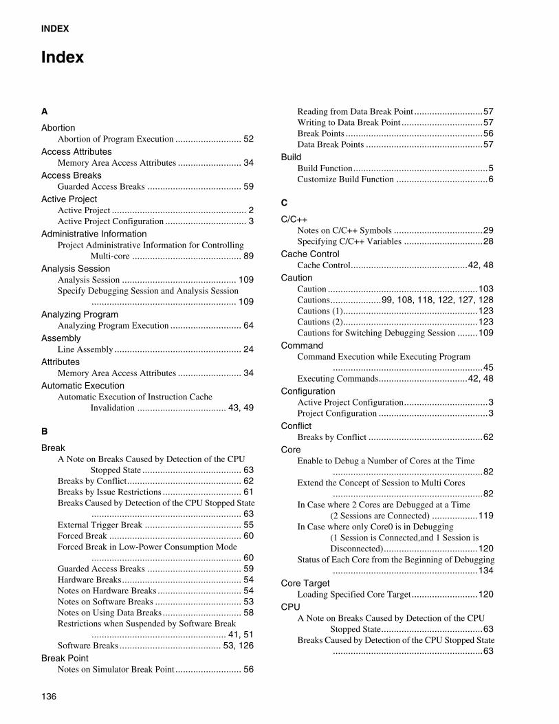
INDEX
Index
A
AbortionAbortion of Program Execution .......................... 52
Access AttributesMemory Area Access Attributes ......................... 34
Access BreaksGuarded Access Breaks ..................................... 59
Active ProjectActive Project ..................................................... 2Active Project Configuration ................................ 3
Administrative InformationProject Administrative Information for Controlling
Multi-core ........................................... 89Analysis Session
Analysis Session ............................................. 109Specify Debugging Session and Analysis Session
......................................................... 109Analyzing Program
Analyzing Program Execution ............................ 64Assembly
Line Assembly .................................................. 24Attributes
Memory Area Access Attributes ......................... 34Automatic Execution
Automatic Execution of Instruction Cache Invalidation ................................... 43, 49
B
BreakA Note on Breaks Caused by Detection of the CPU
Stopped State ....................................... 63Breaks by Conflict............................................. 62Breaks by Issue Restrictions ............................... 61Breaks Caused by Detection of the CPU Stopped State
........................................................... 63External Trigger Break ...................................... 55Forced Break .................................................... 60Forced Break in Low-Power Consumption Mode
........................................................... 60Guarded Access Breaks ..................................... 59Hardware Breaks............................................... 54Notes on Hardware Breaks ................................. 54Notes on Software Breaks .................................. 53Notes on Using Data Breaks ............................... 58Restrictions when Suspended by Software Break
..................................................... 41, 51Software Breaks ........................................ 53, 126
Break PointNotes on Simulator Break Point .......................... 56
Reading from Data Break Point ...........................57Writing to Data Break Point ................................57Break Points ......................................................56Data Break Points ..............................................57
BuildBuild Function.....................................................5Customize Build Function ....................................6
C
C/C++Notes on C/C++ Symbols ...................................29Specifying C/C++ Variables ...............................28
Cache ControlCache Control..............................................42, 48
CautionCaution ...........................................................103Cautions....................99, 108, 118, 122, 127, 128Cautions (1).....................................................123Cautions (2).....................................................123Cautions for Switching Debugging Session ........109
CommandCommand Execution while Executing Program
...........................................................45Executing Commands...................................42, 48
ConfigurationActive Project Configuration.................................3Project Configuration ...........................................3
ConflictBreaks by Conflict .............................................62
CoreEnable to Debug a Number of Cores at the Time
...........................................................82Extend the Concept of Session to Multi Cores
...........................................................82In Case where 2 Cores are Debugged at a Time
(2 Sessions are Connected) ..................119In Case where only Core0 is in Debugging
(1 Session is Connected,and 1 Session is Disconnected).....................................120
Status of Each Core from the Beginning of Debugging.........................................................134
Core TargetLoading Specified Core Target..........................120
CPUA Note on Breaks Caused by Detection of the CPU
Stopped State........................................63Breaks Caused by Detection of the CPU Stopped State
...........................................................63
136
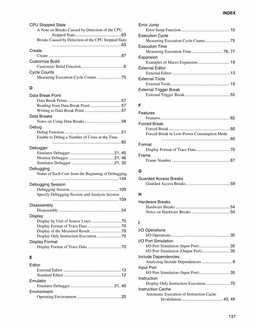
INDEX
CPU Stopped StateA Note on Breaks Caused by Detection of the CPU
Stopped State........................................63Breaks Caused by Detection of the CPU Stopped State
............................................................63Create
Create ...............................................................87Customize Build
Customize Build Function.....................................6Cycle Counts
Measuring Execution Cycle Counts .....................75
D
Data Break PointData Break Points ..............................................57Reading from Data Break Point ...........................57Writing to Data Break Point ................................57
Data BreaksNotes on Using Data Breaks................................58
DebugDebug Function .................................................21Enable to Debug a Number of Cores at the Time
............................................................82Debugger
Emulator Debugger ......................................21, 40Monitor Debugger........................................21, 46Simulator Debugger .....................................21, 32
DebuggingStatus of Each Core from the Beginning of Debugging
..........................................................134Debugging Session
Debugging Session...........................................109Specify Debugging Session and Analysis Session
..........................................................109Disassembly
Disassembly ......................................................24Display
Display by Unit of Source Lines ..........................70Display Format of Trace Data .............................70Display of the Measured Result ...........................79Display Only Instruction Execution .....................70
Display FormatDisplay Format of Trace Data .............................70
E
EditorExternal Editor ..................................................13Standard Editor ..................................................12
EmulatorEmulator Debugger ......................................21, 40
EnvironmentOperating Environment ......................................20
Error JumpError Jump Function .......................................... 10
Execution CycleMeasuring Execution Cycle Counts ..................... 75
Execution TimeMeasuring Execution Time........................... 76, 77
ExpansionExamples of Macro Expansion............................ 19
External EditorExternal Editor .................................................. 13
External ToolsExternal Tools ................................................... 15
External Trigger BreakExternal Trigger Break....................................... 55
F
FeaturesFeatures ............................................................ 82
Forced BreakForced Break..................................................... 60Forced Break in Low-Power Consumption Mode
........................................................... 60Format
Display Format of Trace Data ............................. 70Frame
Frame Number .................................................. 67
G
Guarded Access BreaksGuarded Access Breaks...................................... 59
H
Hardware BreaksHardware Breaks ............................................... 54Notes on Hardware Breaks ................................. 54
I
I/O OperationsI/O Operations................................................... 30
I/O Port SimulationI/O Port Simulation (Input Port) .......................... 35I/O Port Simulation (Output Port)........................ 35
Include DependenciesAnalyzing Include Dependencies .......................... 8
Input PortI/O Port Simulation (Input Port) .......................... 35
InstructionDisplay Only Instruction Execution ..................... 70
Instruction CacheAutomatic Execution of Instruction Cache
Invalidation .................................... 43, 49
137
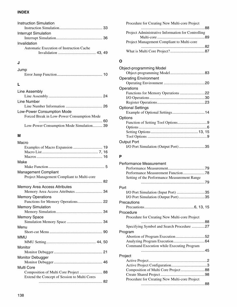
INDEX
Instruction SimulationInstruction Simulation........................................ 33
Interrupt SimulationInterrupt Simulation........................................... 36
InvalidationAutomatic Execution of Instruction Cache
Invalidation ................................... 43, 49
J
JumpError Jump Function .......................................... 10
L
Line AssemblyLine Assembly .................................................. 24
Line NumberLine Number Information .................................. 26
Low-Power Consumption ModeForced Break in Low-Power Consumption Mode
........................................................... 60Low-Power Consumption Mode Simulation......... 39
M
MacroExamples of Macro Expansion ........................... 19Macro List .................................................... 7, 16Macros ............................................................. 16
MakeMake Function .................................................... 5
Management CompliantProject Management Compliant to Multi-core
........................................................... 82Memory Area Access Attributes
Memory Area Access Attributes ......................... 34Memory Operations
Functions for Memory Operations....................... 22Memory Simulation
Memory Simulation........................................... 34Memory Space
Simulation Memory Space ................................. 34Menu
Short-cut Menu ................................................. 90MMU
MMU Setting.............................................. 44, 50Monitor
Monitor Debugger ............................................. 21Monitor Debugger
Monitor Debugger ............................................. 46Multi Core
Composition of Multi Core Project ..................... 88Extend the Concept of Session to Multi Cores
........................................................... 82
Procedure for Creating New Multi-core Project...........................................................88
Project Administrative Information for Controlling Multi-core ............................................89
Project Management Compliant to Multi-core...........................................................82
What is Multi Core Project? ................................87
O
Object-programming ModelObject-programming Model................................83
Operating EnvironmentOperating Environment ......................................20
OperationsFunctions for Memory Operations .......................22I/O Operations ...................................................30Register Operations............................................23
Optional SettingsExample of Optional Settings..............................14
OptionsFunction of Setting Tool Options...........................9Options ...............................................................6Setting Options ............................................13, 15Tool Options .......................................................9
Output PortI/O Port Simulation (Output Port) ........................35
P
Performance MeasurementPerformance Measurement..................................79Performance Measurement Function ....................78Setting of the Performance Measurement Range
...........................................................79Port
I/O Port Simulation (Input Port) ..........................35I/O Port Simulation (Output Port) ........................35
PrecautionsPrecautions..............................................6, 13, 15
ProcedureProcedure for Creating New Multi-core Project
...........................................................88Specifying Symbol and Search Procedure ............27
ProgramAbortion of Program Execution...........................52Analyzing Program Execution.............................64Command Execution while Executing Program
...........................................................45Project
Active Project......................................................2Active Project Configuration.................................3Composition of Multi Core Project ......................88Create Shared Project .........................................98Procedure for Creating New Multi-core Project
...........................................................88
138
INDEX
Project ................................................................2Project Administrative Information for Controlling
Multi-core ............................................89Project Configuration ...........................................3Project Dependence..............................................4Project Management Compliant to Multi-core
............................................................82Project Management Function ...............................3Restrictions on Storage of Two or More Projects
..............................................................2What is Multi Core Project? ................................87
R
ReferenceReference Section
....................9, 11, 12, 14, 15, 20, 23, 24Register Operations
Register Operations ............................................23Reset Simulation
Reset Simulation ................................................38Resources
Required Resources............................................47Restrictions
Breaks by Issue Restrictions................................61
S
ScopeMoving Scope ...................................................27Scope................................................................27
Search ProcedureSpecifying Symbol and Search Procedure.............27
Debugging SessionCautions for Switching Debugging Session ........109
SectionReference Section
....................9, 11, 12, 14, 15, 20, 23, 24Session
Analysis Session ..............................................109Cautions for Switching Debugging Session ........109Debugging Session...........................................109Extend the Concept of Session to Multi Cores
............................................................82In Case where 2 Cores are Debugged at a Time
(2 Sessions are Connected) ..................119In Case where only Core0 is in Debugging
(1 Session is Connected,and 1 Session is Disconnected).....................................120
Specify Debugging Session and Analysis Session..........................................................109
Shared ProjectCreate Shared Project .........................................98
Short-cut MenuShort-cut Menu ..................................................90
SimulationI/O Port Simulation (Input Port) .......................... 35I/O Port Simulation (Output Port)........................ 35Instruction Simulation ........................................ 33Interrupt Simulation ........................................... 36Low-Power Consumption Mode Simulation ......... 39Memory Simulation ........................................... 34Reset Simulation ............................................... 38Simulation Memory Space.................................. 34Simulation Range .............................................. 32
SimulatorSimulator Debugger ..................................... 21, 32
Simulator Break PointNotes on Simulator Break Point .......................... 56
Software BreakNotes on Software Breaks .................................. 53Restrictions when Suspended by Software Break
..................................................... 41, 51Software Breaks ........................................ 53, 126
Source LinesDisplay by Unit of Source Lines ......................... 70
Standard EditorStandard Editor ................................................. 12
StatusStatus of Each Core from the Beginning of Debugging
......................................................... 134Stopped State
A Note on Breaks Caused by Detection of the CPU Stopped State ....................................... 63
Breaks Caused by Detection of the CPU Stopped State........................................................... 63
StorageRestrictions on Storage of Two or More Projects
............................................................. 2Subproject
Subproject........................................................... 2Symbol
Notes on C/C++ Symbols ................................... 29Setting Symbol Information................................ 25Specifying Symbol and Search Procedure ............ 27Types of Symbols .............................................. 25
SyntaxSyntax .............................................................. 10
T
TargetLoading Specified Core Target ......................... 120
ToolExternal Tools ................................................... 15Function of Setting Tool Options .......................... 9Tool Options ....................................................... 9
TraceClearing Trace Data ........................................... 73Display Format of Trace Data ............................. 70
139
INDEX
Displaying Trace Data ....................................... 69Notes on Trace Function .................................... 74Saving Trace Data ............................................. 72Searching Trace Data......................................... 71Setting Trace..................................................... 68Trace........................................................ 65, 131Trace Data ........................................................ 66
Tracing FunctionTracing Function ............................................... 67
V
VariablesSpecifying C/C++ Variables ............................... 28
W
WizardSet Up Wizard ........................................ 111, 115
WorkspaceWorkspace.......................................................... 2Workspace Management Function ........................ 2
140
CM71-00333-2E
FUJITSU SEMICONDUCTOR • CONTROLLER MANUAL
FR-V FAMILY
SOFTUNETM Workbench
USER’S MANUAL
for V6
June 2006 the second edition
Published FUJITSU LIMITED Electronic Devices
Edited Business Promotion Dept.