Embed Size (px)
Citation preview
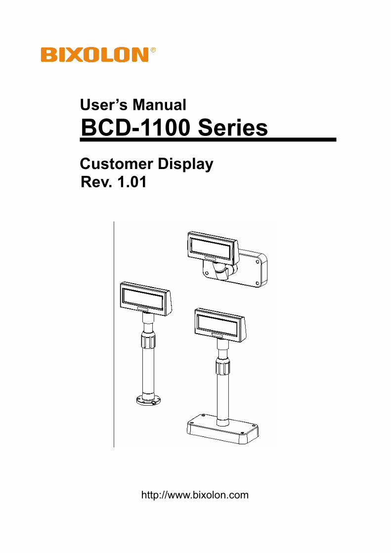
User’s Manual BCD-1100 Series Customer Display Rev. 1.01
http://www.bixolon.com
Rev. 1.01 - 2 -
BCD-1100
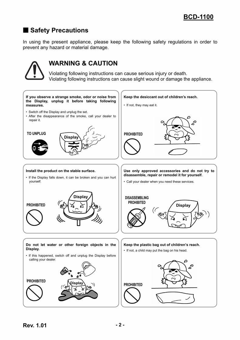
■ Safety Precautions In using the present appliance, please keep the following safety regulations in order to prevent any hazard or material damage.
WARNING & CAUTION Violating following instructions can cause serious injury or death. Violating following instructions can cause slight wound or damage the appliance.
If you observe a strange smoke, odor or noise from the Display, unplug it before taking following measures.
• Switch off the Display and unplug the set. • After the disappearance of the smoke, call your dealer to
repair it.
Display TO UNPLUG
Keep the desiccant out of children’s reach.
• If not, they may eat it.
PROHIBITED
Install the product on the stable surface.
• If the Display falls down, it can be broken and you can hurt yourself.
Display
PROHIBITED
Use only approved accessories and do not try to disassemble, repair or remodel it for yourself.
• Call your dealer when you need these services.
Display
DISASSEMBLINGPROHIBITED
Do not let water or other foreign objects in the Display.
• If this happened, switch off and unplug the Display before calling your dealer.
Display PROHIBITED PROHIBITED
Keep the plastic bag out of children’s reach. • If not, a child may put the bag on his head.
PROHIBITED
Rev. 1.01 - 3 -
BCD-1100
■ Table of Contents 1. Complete Product Configuration................................................................................. 4
2. Unpacking ..................................................................................................................... 5 2-1 BCD-1100DN Type.................................................................................................... 5 2-2 BCD-1100D Type ...................................................................................................... 5 2-3 BCD-1100W Type...................................................................................................... 6 2-4 BCD-1100WN Type................................................................................................... 6
3. Connection Type........................................................................................................... 7
4. Size................................................................................................................................. 8 4-1 Desk Top Type .......................................................................................................... 8 4-2 Wall Mount Type........................................................................................................ 8 4-3 Etc. ............................................................................................................................ 8
5. Function......................................................................................................................... 9 5-1 Rotation ..................................................................................................................... 9 5-2 Angling..................................................................................................................... 10
6. Switches ...................................................................................................................... 11 6-1 Display Switch ......................................................................................................... 11 6-2 DIP switches............................................................................................................ 11 6-3 Memory Switches .................................................................................................... 12
7. USB Virtual COM Installation..................................................................................... 13
8. Appendix ..................................................................................................................... 17 8-1 Specifications .......................................................................................................... 17 8-2 Certification.............................................................................................................. 17 8-3 Label Types ............................................................................................................. 18
Rev. 1.01 - 4 -
BCD-1100
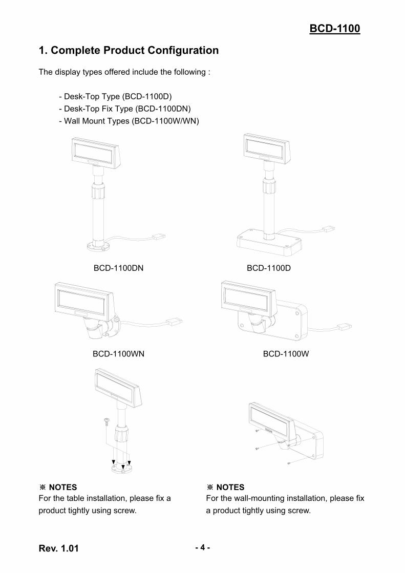
1. Complete Product Configuration The display types offered include the following :
- Desk-Top Type (BCD-1100D) - Desk-Top Fix Type (BCD-1100DN) - Wall Mount Types (BCD-1100W/WN)
BCD-1100DN
BCD-1100D
BCD-1100WN
BCD-1100W
※ NOTES For the table installation, please fix a product tightly using screw.
※ NOTES For the wall-mounting installation, please fix a product tightly using screw.
Rev. 1.01 - 5 -
BCD-1100
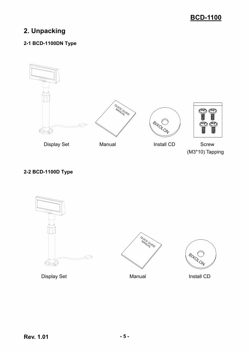
2. Unpacking 2-1 BCD-1100DN Type
Display Set Manual Install CD Screw (M3*10) Tapping
2-2 BCD-1100D Type
Display Set Manual Install CD
Rev. 1.01 - 6 -
BCD-1100
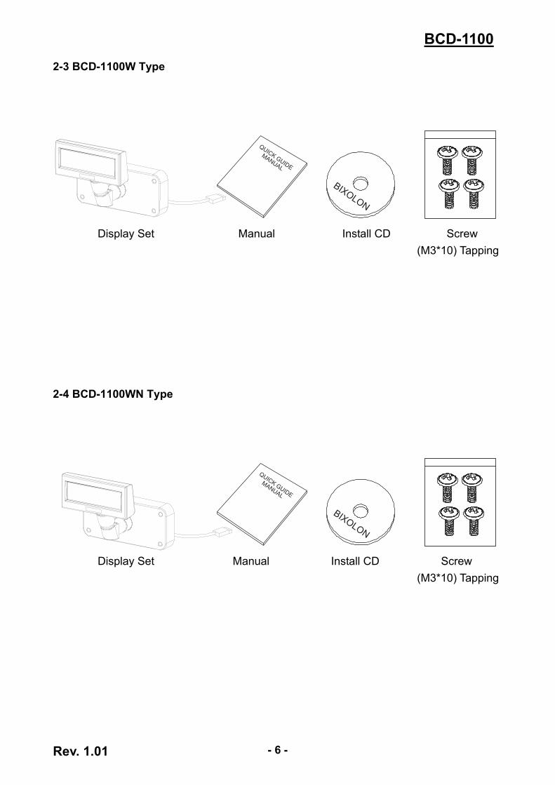
2-3 BCD-1100W Type
Display Set Manual Install CD Screw (M3*10) Tapping
2-4 BCD-1100WN Type
Display Set Manual Install CD Screw (M3*10) Tapping
Rev. 1.01 - 7 -
BCD-1100
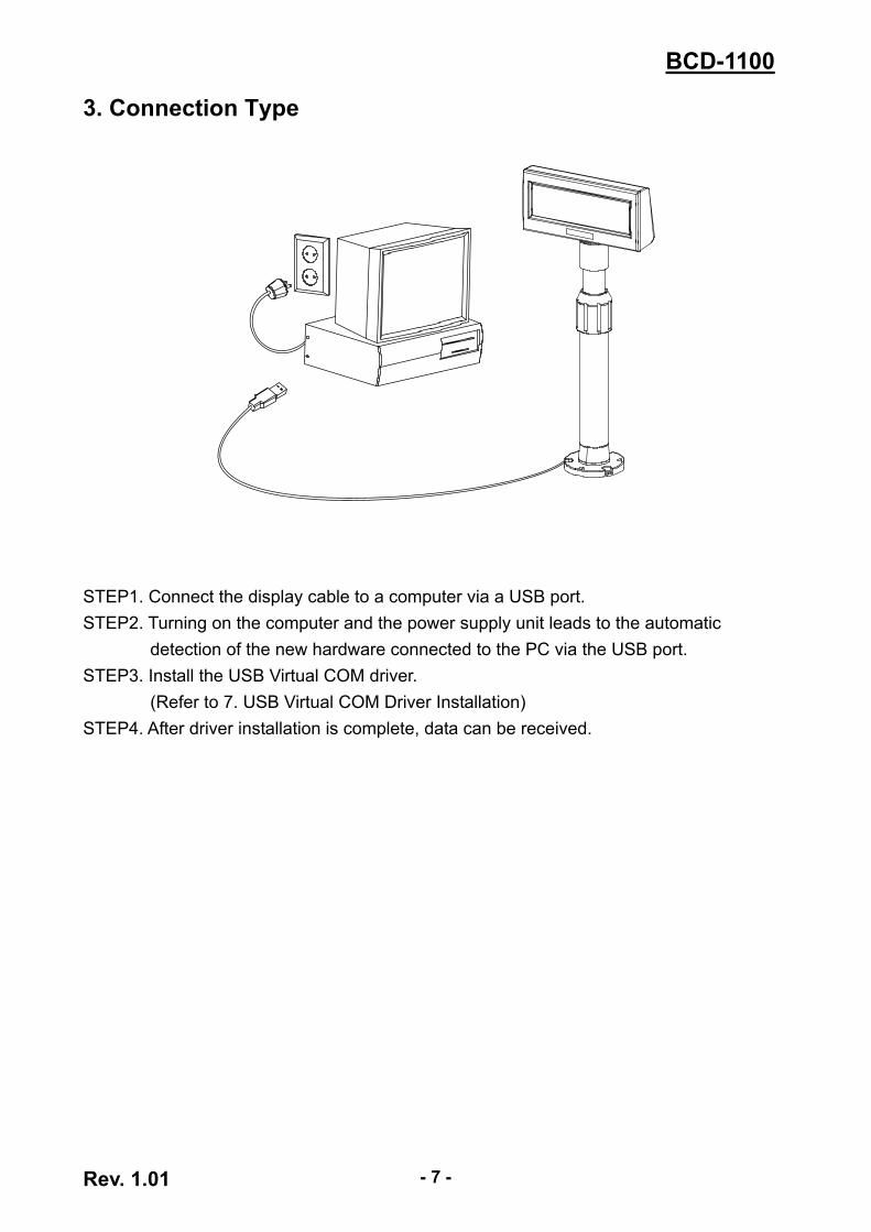
3. Connection Type
STEP1. Connect the display cable to a computer via a USB port. STEP2. Turning on the computer and the power supply unit leads to the automatic
detection of the new hardware connected to the PC via the USB port. STEP3. Install the USB Virtual COM driver.
(Refer to 7. USB Virtual COM Driver Installation) STEP4. After driver installation is complete, data can be received.
Rev. 1.01 - 8 -
BCD-1100
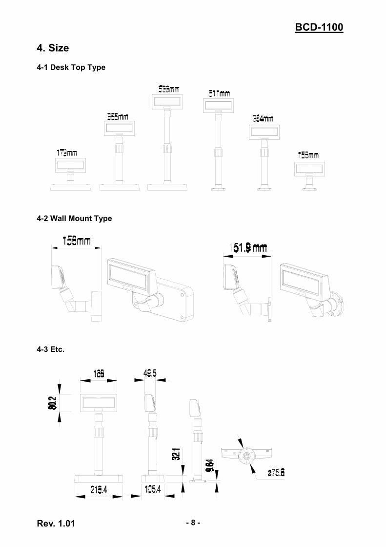
4. Size 4-1 Desk Top Type
4-2 Wall Mount Type
4-3 Etc.
Rev. 1.01 - 9 -
BCD-1100
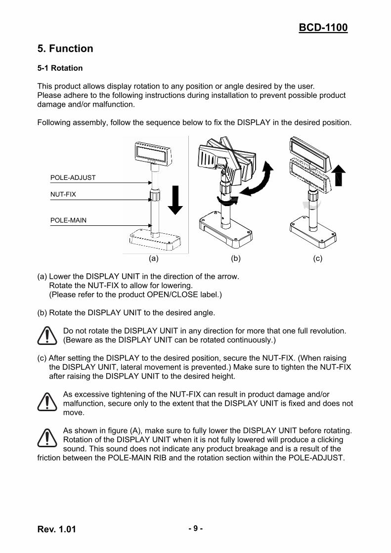
5. Function 5-1 Rotation This product allows display rotation to any position or angle desired by the user. Please adhere to the following instructions during installation to prevent possible product damage and/or malfunction. Following assembly, follow the sequence below to fix the DISPLAY in the desired position.
(a) (b) (c)
POLE-ADJUST
NUT-FIX
POLE-MAIN
(a) Lower the DISPLAY UNIT in the direction of the arrow.
Rotate the NUT-FIX to allow for lowering. (Please refer to the product OPEN/CLOSE label.)
(b) Rotate the DISPLAY UNIT to the desired angle.
Do not rotate the DISPLAY UNIT in any direction for more that one full revolution. (Beware as the DISPLAY UNIT can be rotated continuously.)
(c) After setting the DISPLAY to the desired position, secure the NUT-FIX. (When raising the DISPLAY UNIT, lateral movement is prevented.) Make sure to tighten the NUT-FIX after raising the DISPLAY UNIT to the desired height.
As excessive tightening of the NUT-FIX can result in product damage and/or malfunction, secure only to the extent that the DISPLAY UNIT is fixed and does not move.
As shown in figure (A), make sure to fully lower the DISPLAY UNIT before rotating. Rotation of the DISPLAY UNIT when it is not fully lowered will produce a clicking sound. This sound does not indicate any product breakage and is a result of the
friction between the POLE-MAIN RIB and the rotation section within the POLE-ADJUST.
Rev. 1.01 - 10 -
BCD-1100
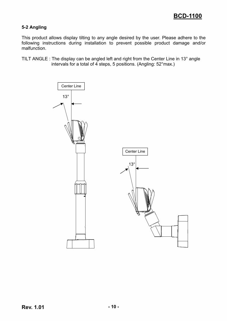
5-2 Angling This product allows display tilting to any angle desired by the user. Please adhere to the following instructions during installation to prevent possible product damage and/or malfunction. TILT ANGLE : The display can be angled left and right from the Center Line in 13° angle
intervals for a total of 4 steps, 5 positions. (Angling: 52°max.)
Center Line
Center Line
Rev. 1.01 - 11 -
BCD-1100
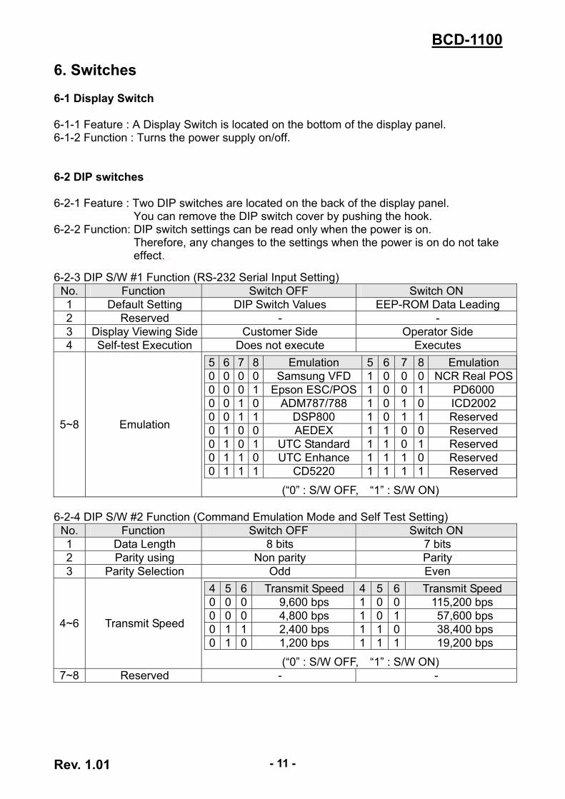
6. Switches 6-1 Display Switch 6-1-1 Feature : A Display Switch is located on the bottom of the display panel. 6-1-2 Function : Turns the power supply on/off. 6-2 DIP switches 6-2-1 Feature : Two DIP switches are located on the back of the display panel.
You can remove the DIP switch cover by pushing the hook. 6-2-2 Function: DIP switch settings can be read only when the power is on.
Therefore, any changes to the settings when the power is on do not take effect.
6-2-3 DIP S/W #1 Function (RS-232 Serial Input Setting)
No. Function Switch OFF Switch ON 1 Default Setting DIP Switch Values EEP-ROM Data Leading 2 Reserved - - 3 Display Viewing Side Customer Side Operator Side 4 Self-test Execution Does not execute Executes
5~8 Emulation
5 6 7 8 Emulation 5 6 7 8 Emulation 0 0 0 0 Samsung VFD 1 0 0 0 NCR Real POS0 0 0 1 Epson ESC/POS 1 0 0 1 PD6000 0 0 1 0 ADM787/788 1 0 1 0 ICD2002 0 0 1 1 DSP800 1 0 1 1 Reserved 0 1 0 0 AEDEX 1 1 0 0 Reserved 0 1 0 1 UTC Standard 1 1 0 1 Reserved 0 1 1 0 UTC Enhance 1 1 1 0 Reserved 0 1 1 1 CD5220 1 1 1 1 Reserved
(“0” : S/W OFF, “1” : S/W ON) 6-2-4 DIP S/W #2 Function (Command Emulation Mode and Self Test Setting)
No. Function Switch OFF Switch ON 1 Data Length 8 bits 7 bits 2 Parity using Non parity Parity 3 Parity Selection Odd Even
4~6 Transmit Speed
4 5 6 Transmit Speed 4 5 6 Transmit Speed 0 0 0 9,600 bps 1 0 0 115,200 bps 0 0 0 4,800 bps 1 0 1 57,600 bps 0 1 1 2,400 bps 1 1 0 38,400 bps 0 1 0 1,200 bps 1 1 1 19,200 bps
(“0” : S/W OFF, “1” : S/W ON) 7~8 Reserved - -
Rev. 1.01 - 12 -
BCD-1100
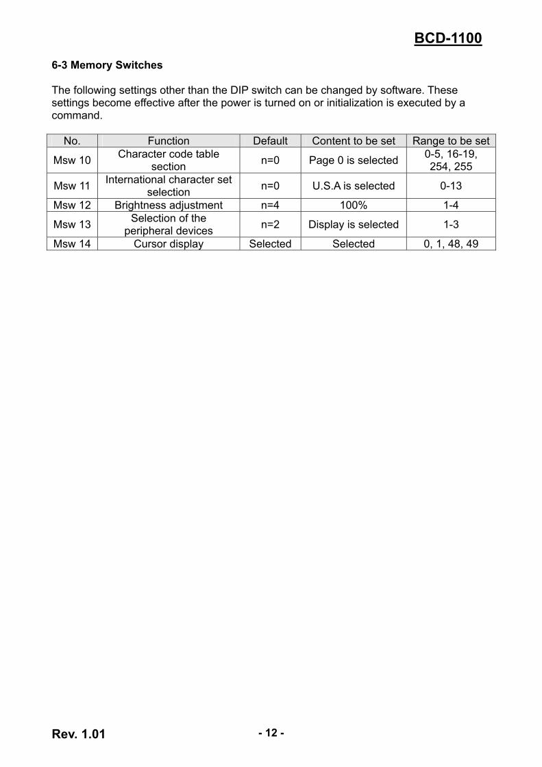
6-3 Memory Switches The following settings other than the DIP switch can be changed by software. These settings become effective after the power is turned on or initialization is executed by a command.
No. Function Default Content to be set Range to be set
Msw 10 Character code table section n=0 Page 0 is selected 0-5, 16-19,
254, 255
Msw 11 International character setselection n=0 U.S.A is selected 0-13
Msw 12 Brightness adjustment n=4 100% 1-4
Msw 13 Selection of the peripheral devices n=2 Display is selected 1-3
Msw 14 Cursor display Selected Selected 0, 1, 48, 49
Rev. 1.01 - 13 -
BCD-1100
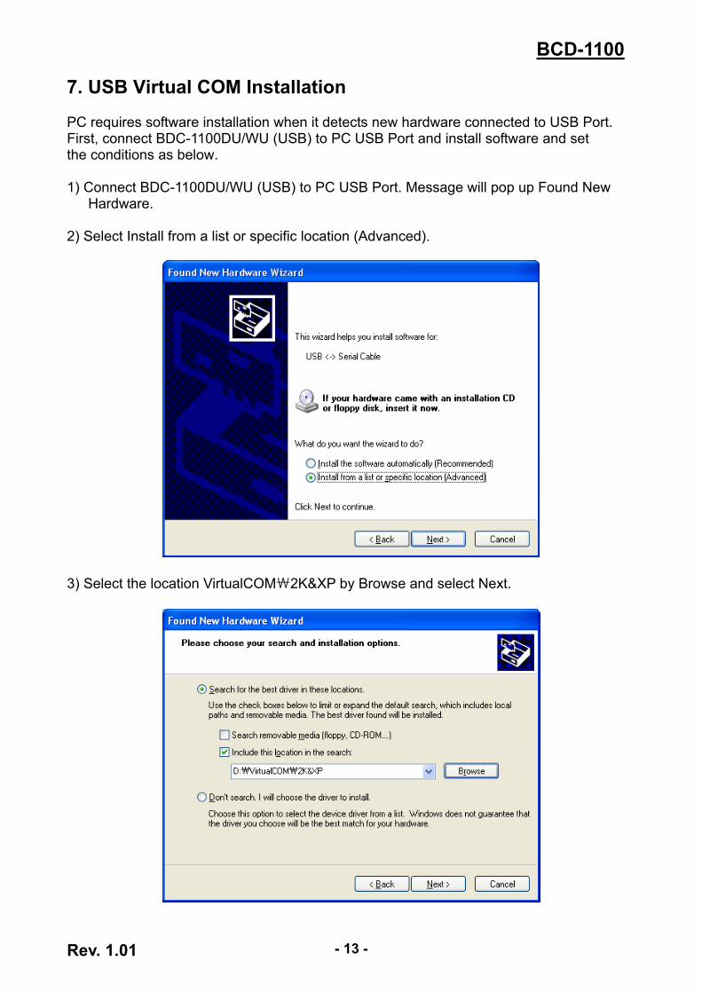
7. USB Virtual COM Installation PC requires software installation when it detects new hardware connected to USB Port. First, connect BDC-1100DU/WU (USB) to PC USB Port and install software and set the conditions as below. 1) Connect BDC-1100DU/WU (USB) to PC USB Port. Message will pop up Found New
Hardware.
2) Select Install from a list or specific location (Advanced).
3) Select the location VirtualCOM₩2K&XP by Browse and select Next.
BCD-1100
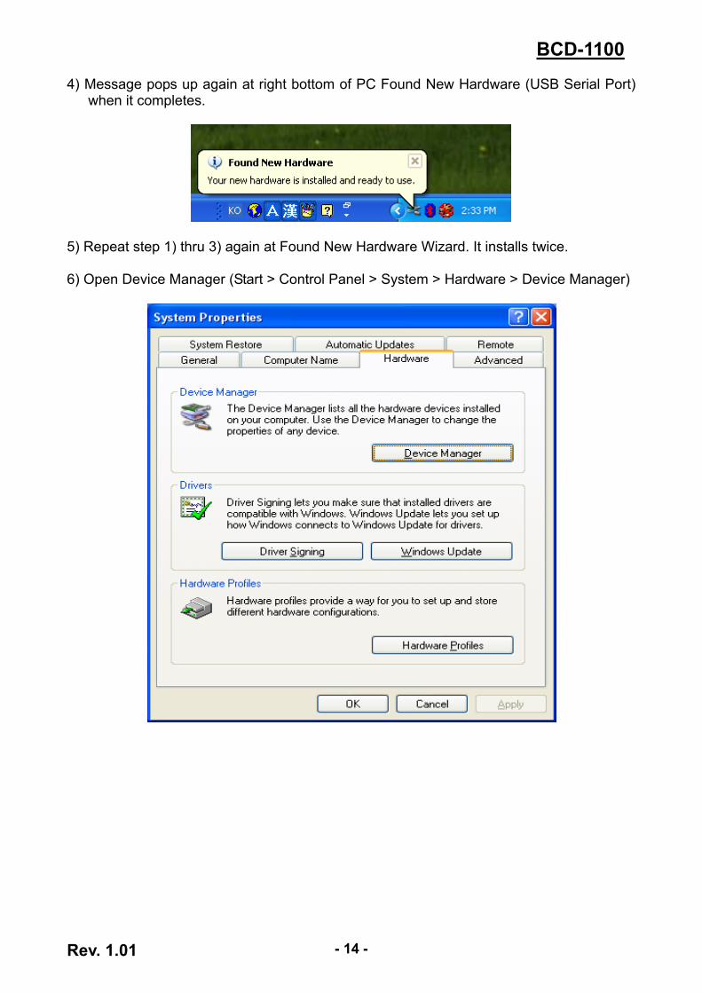
4) Message pops up again at right bottom of PC Found New Hardware (USB Serial Port) when it completes.
5) Repeat step 1) thru 3) again at Found New Hardware Wizard. It installs twice. 6) Open Device Manager (Start > Control Panel > System > Hardware > Device Manager)
Rev. 1.01 - 14 -
Rev. 1.01 - 15 -
BCD-1100
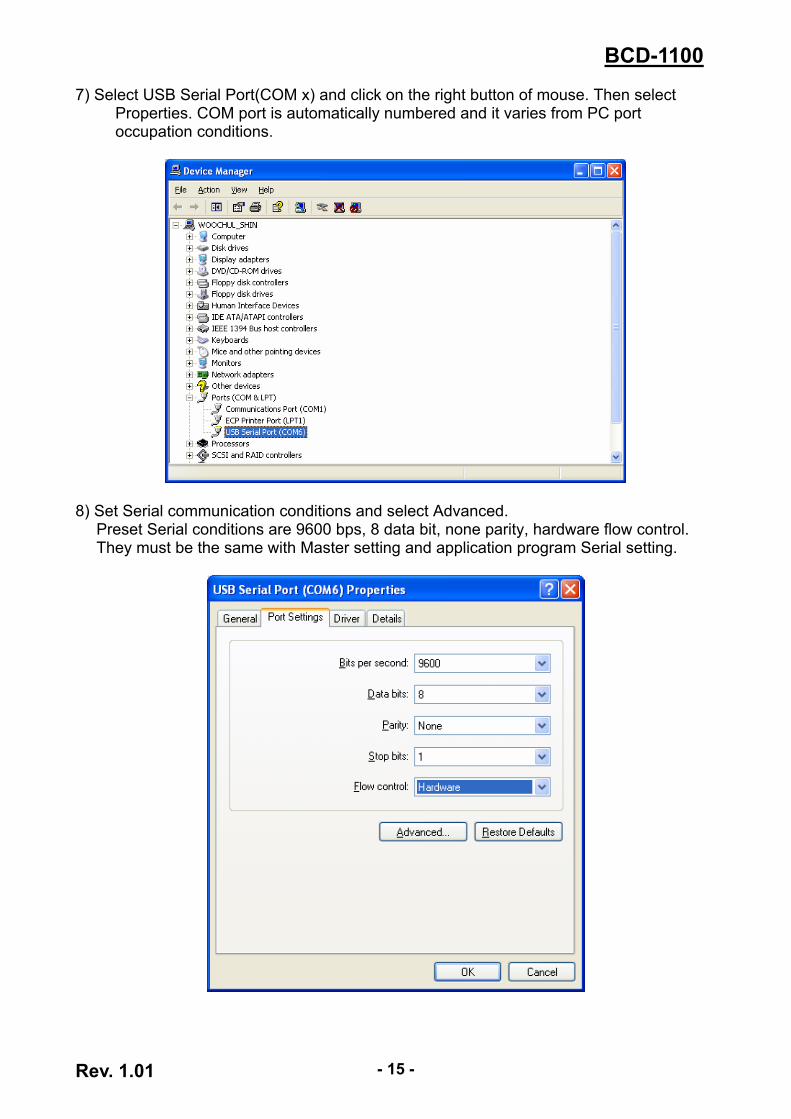
7) Select USB Serial Port(COM x) and click on the right button of mouse. Then select Properties. COM port is automatically numbered and it varies from PC port occupation conditions.
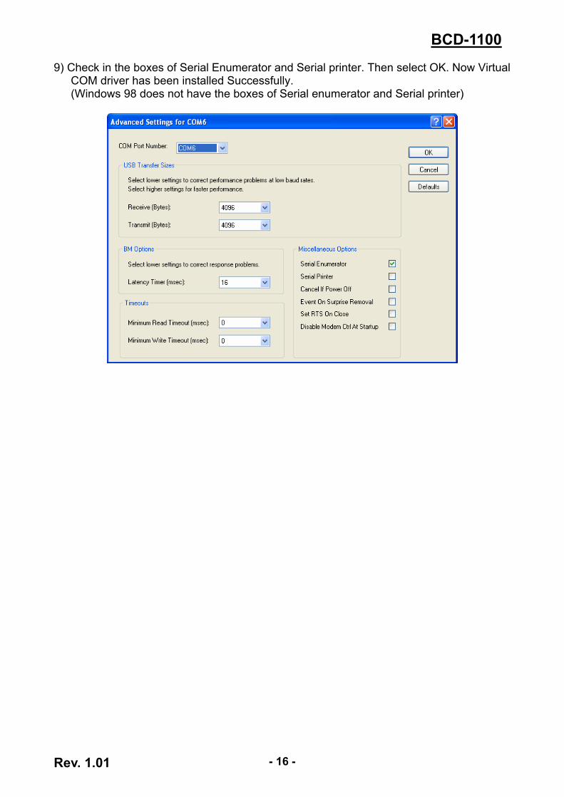
8) Set Serial communication conditions and select Advanced.
Preset Serial conditions are 9600 bps, 8 data bit, none parity, hardware flow control. They must be the same with Master setting and application program Serial setting.
Rev. 1.01 - 16 -
BCD-1100
9) Check in the boxes of Serial Enumerator and Serial printer. Then select OK. Now Virtual COM driver has been installed Successfully. (Windows 98 does not have the boxes of Serial enumerator and Serial printer)
Rev. 1.01 - 17 -
BCD-1100
8. Appendix 8-1 Specifications
Item Description Display Method VFD Brightness 700 [cd/㎡] Character Size 5 x 7 [dot] Number of Columns 20 character, 2 line Operating Temperature 0~45 ℃
Display
Operating Humidity 10~80 % Reliability VFD 20,000 [hour]
* This equipment is indooruse and all the communication hiring are limited to inside of the
building. * The switch is the disconnecting device. Turn off switch from any hazard. 8-2 Certification 1) EMC & Safety Standards
• Europe: CE EMC, TUV GS: EN60950-1: 2001 • North America: FCC Part 15 Subpart B • Safety Standards: CB-scheme: IEC60950-1: 2001
WARNING
Use of an unprotected interface cable with this device conflicts with EMC standards. Users should only use cables approved by BIXOLON. 2) CE Mark
• EMC Directive 89/336/EEC EN 55022:1994 +A1:1995 +A2:1997 EN 61000-3-2:2000 EN 61000-3-3:1995 +A1:2001 EN 55024:1998 +A1:2001 EN 61000-4-2:1995 +A1:1998 +A2:2001 EN 61000-4-3:1996 +A1:1998 +A2:2001 EN 61000-4-4:2004 EN 61000-4-5:1995 +A1:2001 EN 61000-4-6:1996 +A1:2001 EN 61000-4-11:1994 +A1:2001
• Radio Spectrum EN300328 v1.6.1 • Low Voltage Directive 73/23/EEC Safety: EN60950-1:2001
Rev. 1.01 - 18 -
BCD-1100
3) WEEE (Waste Electrical and Electric Equipment)
This marking shown on the product or its literature, indicates that it should not be disposed with other household wastes at the end of its working life. To prevent possible harm to the environment or human health from uncontrolled waste disposal, please separate this from other types of wastes and recycle it responsibly to promote the sustainable reuse of material resources. Household users should contact either the retailer where they purchased this product, or
their local government office, for details of where and how they can take this item for environmentally safe recycling. Business users should contact their supplier and check the terms and conditions of the purchase contract. This product should not be mixed with other commercial wastes for disposal.
8-3 Label Types The label types used with this printer is as follows.
• BIXOLON Logo Labels: PET • Rating Labels: PP • Other Labels: PET