Embed Size (px)
Citation preview

SPA OPC Server
User’s Manual
Industrial IT enabled products from ABB are the building blocks for greater productivity, featuring all the tools necessary for lifecycle product support in consistent electronic form.

SPA OPC ServerVersion 1.0User’s Manual


NOTICEThe information in this document is subject to change without notice andshould not be construed as a commitment by ABB Oy. ABB Oy assumes noresponsibility for any errors that may appear in this document.
In no event shall ABB Oy be liable for direct, indirect, special, incidental orconsequential damages of any nature or kind arising from the use of this doc-ument, nor shall ABB Oy be liable for incidental or consequential damagesarising from use of any software or hardware described in this document.
This document and parts thereof must not be reproduced or copied withoutwritten permission from ABB Oy, and the contents thereof must not be im-parted to a third party nor used for any unauthorized purpose.
The software or hardware described in this document is furnished under a li-cense and may be used, copied, or disclosed only in accordance with theterms of such license.
Copyright © 2003 ABB Oy All rights reserved.
DOCUMENT REVISIONSDocument number: 1MRS755221Release: 12.2003
TRADEMARKSRegistrations and trademarks used in this document include:
Windows Registered trademark of Microsoft Corporation.
Acrobat Reader Registered trademark of Adobe Systems Inc.
Version Issued date Revised
A 12.2003

This user’s manual describes the stand-alone SPA OPC Server and the central concepts related to it. You will find instructions on how to install the SPA OPC Server and how to take it into use. The basic operation procedures are also discussed.
Information in this user’s manual is intended for application engineers who install and configure the SPA OPC Server.
As a prerequisite, you should have some previous knowledge of SPA devices.
This user’s manual is divided into following sections:
Section 1 - Introduction
This section gives an overview of the SPA OPC Server and states the system requirements that need to be met when using the server.
Section 2 - Installation
This section provides you with instructions on how to install the SPA OPC Server software and other required software and hardware components.
Section 3 - Features
This section gives an overview of the features of the SPA OPC Server.
Section 4 - Engineering
In this section you will find an overview of engineering. You are given instructions on how to configure the SPA OPC Server related objects.
Use of warning, caution, information, and tip iconsThis publication includes warning, caution, and information icons that point out safetyrelated conditions or other important information. It also includes tip icons to point outuseful information to the reader. The corresponding icons should be interpreted asfollows:
An electrical warning icon indicates the presence of a hazard which could result in electrical shock.
7
1MRS755221ABOUT THIS BOOKABOUT THIS BOOK
Note: Although warning hazards are related to personal injury, and caution hazards areassociated with equipment or property damage, it should be understood that operation ofdamaged equipment could, under certain operational conditions, result in degradedprocess performance leading to personal injury or death. Therefore, comply fully with allwarning and caution notices.
Document conventionsThe following conventions are used for the presentation of material:
• The words in names of screen elements (for example, the title in the title bar of a window, the label for a field of a dialog box) are initially capitalized.
• Capital letters are used for the name of a keyboard key if it is labeled on the keyboard. For example, press the ENTER key.
• Lowercase letters are used for the name of a keyboard key that is not labeled on the keyboard. For example, the space bar, comma key, and so on.
• Press CTRL+C indicates that you must hold down the CTRL key while pressing the C key (to copy a selected object in this case).
• Press ESC E C indicates that you press and release each key in sequence (to copy a selected object in this case).
• The names of push and toggle buttons are boldfaced. For example, click OK.
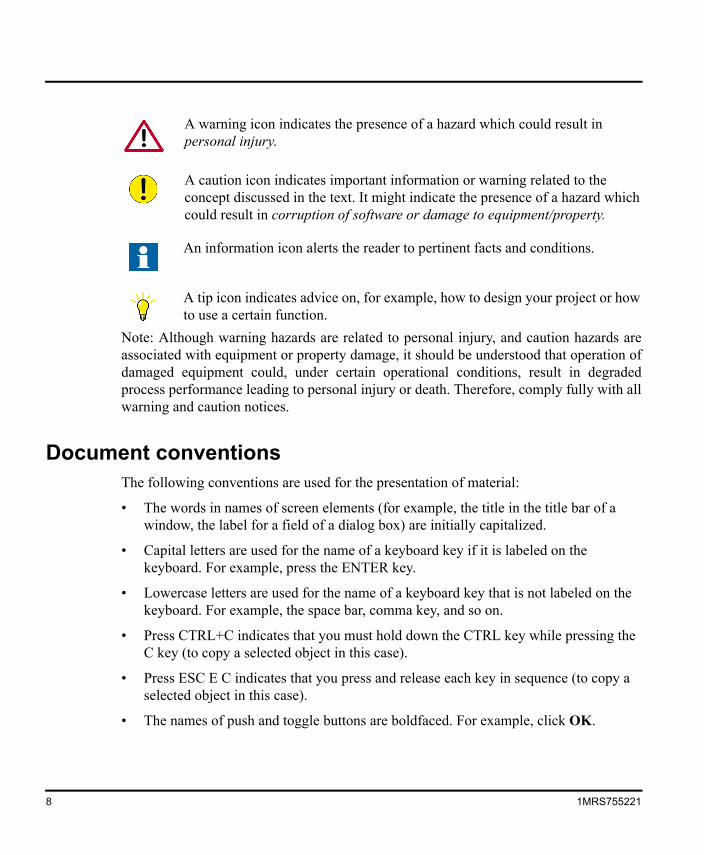
A warning icon indicates the presence of a hazard which could result in personal injury.
A caution icon indicates important information or warning related to the concept discussed in the text. It might indicate the presence of a hazard which could result in corruption of software or damage to equipment/property.
An information icon alerts the reader to pertinent facts and conditions.
A tip icon indicates advice on, for example, how to design your project or how to use a certain function.
8 1MRS755221
• The names of menus and menu items are boldfaced. For example, the File menu.
– The following convention is used for menu operations: MenuName > MenuItem > CascadedMenuItem. For example: select File > New > Type.
– The Start menu name always refers to the Start menu on the Windows Task Bar.
• System prompts/messages and user responses/input are shown in the Courier font. For example, if you enter a value out of range, the following message is displayed:
Entered value is not valid. The value must be 0 to 30.
You may be told to enter the string MIF349 in a field. The string is shown as follows in the procedure:
MIF349
• Variables are shown using lowercase letters:
sequence name
• All the figures in this document have been taken using Windows XP.
TerminologyThe following is a list of terms associated with the SPA OPC Server that you should be familiar with. The list contains terms that are unique to ABB or have a usage or definition that is different from the standard industry usage.
Term Description
Data Access; DA An OPC service for providing information about process data to OPC clients.
Device A physical device that behaves as its own communication node in the network, e.g. protection relay.
OPC item Representation of connections to data sources, i.e. object properties. An OPC item is identified by a string. Associated with each OPC item are Value, Quality and Time Stamp.
1MRS755221 9
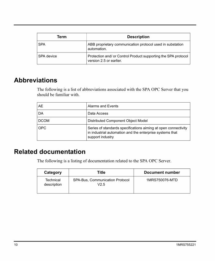
AbbreviationsThe following is a list of abbreviations associated with the SPA OPC Server that you should be familiar with.
Related documentationThe following is a listing of documentation related to the SPA OPC Server.
SPA ABB proprietary communication protocol used in substation automation.
SPA device Protection and/ or Control Product supporting the SPA protocol version 2.5 or earlier.
AE Alarms and Events
DA Data Access
DCOM Distributed Component Object Model
OPC Series of standards specifications aiming at open connectivity in industrial automation and the enterprise systems that support industry
Category Title Document number
Technical description
SPA-Bus, Communication Protocol V2.5
1MRS750076-MTD
Term Description
10 1MRS755221
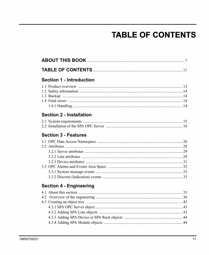
ABOUT THIS BOOK ................................................................................................... 7
TABLE OF CONTENTS ...........................................................................................11
Section 1 - Introduction1.1 Product overview ..........................................................................................................131.2 Safety information .........................................................................................................141.3 Backup ..........................................................................................................................141.4 Fatal errors ....................................................................................................................14
1.4.1 Handling ...............................................................................................................14
Section 2 - Installation2.1 System requirements .....................................................................................................152.2 Installation of the SPA OPC Server ..............................................................................16
Section 3 - Features3.1 OPC Data Access Namespace .......................................................................................263.2 Attributes .......................................................................................................................28
3.2.1 Server attributes ...................................................................................................293.2.2 Line attributes ......................................................................................................293.2.3 Device attributes ..................................................................................................31
3.3 OPC Alarms and Events Area Space ............................................................................323.3.1 System message events ........................................................................................333.3.2 Discrete (Indication) events .................................................................................33
Section 4 - Engineering4.1 About this section ..........................................................................................................354.2 Overview of the engineering ........................................................................................364.3 Creating an object tree ..................................................................................................43
4.3.1 SPA OPC Server object ........................................................................................434.3.2 Adding SPA Line objects .....................................................................................434.3.3 Adding SPA Device or SPA Rack objects ...........................................................444.3.4 Adding SPA Module objects ................................................................................44
11
1MRS755221TABLE OF CONTENTSTABLE OF CONTENTS
4.3.5 Adding SPA Signal objects .................................................................................. 444.3.6 Deleting and copying objects ............................................................................... 45
4.4 Configuring objects ....................................................................................................... 464.4.1 SPA OPC Server properties ................................................................................. 474.4.2 SPA Line properties ............................................................................................. 484.4.3 SPA Device and SPA Module properties ............................................................. 494.4.4 SPA Signal properties .......................................................................................... 49
4.5 Adding event definitions ............................................................................................... 54
Appendix A - Status Codes
Appendix B - DCOM configuration
INDEX................................................................................................................................ 65
12 1MRS755221
Product overview Section 1 Introduction
Section 1 Introduction
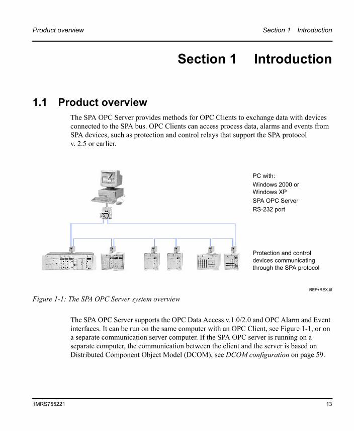
1.1 Product overviewThe SPA OPC Server provides methods for OPC Clients to exchange data with devices connected to the SPA bus. OPC Clients can access process data, alarms and events from SPA devices, such as protection and control relays that support the SPA protocol v. 2.5 or earlier.
The SPA OPC Server supports the OPC Data Access v.1.0/2.0 and OPC Alarm and Event interfaces. It can be run on the same computer with an OPC Client, see Figure 1-1, or on a separate communication server computer. If the SPA OPC server is running on a separate computer, the communication between the client and the server is based on Distributed Component Object Model (DCOM), see DCOM configuration on page 59.
PC with:Windows 2000 orWindows XPSPA OPC ServerRS-232 port
Protection and control devices communicating through the SPA protocol
REF+REX.tif
Figure 1-1: The SPA OPC Server system overview
13
1MRS755221
Section 1 Introduction Safety information
1.2 Safety informationThe purpose of safety information is to provide information on prevention of hazards.
1.3 Backup All the project specific data is stored into the configuration file opcs_net.ini. Therefore it is usually enough to create a backup only for this file. Reinstalling the SPA OPC Server software will restore the rest of the required files.
There are some commercial software packages available for creating a complete image backup for the system, but none of these is delivered with the SPA OPC Server software. The backup image will then contain both the system and application specific files.
1.4 Fatal errorsA fatal error is an error that causes a breakdown or a locked situation in the program.
1.4.1 HandlingIn case of a fatal error:
1. Write down the possible SPA OPC Server error messages.
2. If necessary, shut down the SPA OPC Server program in the WindowsTM1 Task Manager.
3. The data kept in the main memory at the moment of a fatal error is placed in the drwtsn32.log file. It is placed in a system folder, for example Winnt. Analyze and copy the data in this file.
Report the program breakdown together with the possible error messages and the information in the drwtsn32.log file to the SPA OPC Server supplier.
1. Windows is a trademark of Microsoft Corporation.
14 1MRS755221
System requirements Section 2 Installation
Section 2 Installation
This chapter provides information on the system requirements for the SPA OPC Server. It also describes the installation procedure of the SPA OPC Server.
2.1 System requirementsThe SPA OPC Server runs on the Windows 2000 and Windows XP Operating System. A PC capable of running one of these operating systems and applications is usually sufficient also for the SPA OPC Server.
Other system requirements can be seen below.
• 20 MB free hard disk space, if Microsoft .NET Framework 1.1, which is required for running the SPA OPC Server Configuration Tool, has been installed already.
• 100 MB free hard disk space, includes installation of Microsoft .NET Framework 1.1. It is installed automatically, if it is not found.
The following issues affect the performance of the system, and should also be considered when choosing the hardware:
• The number of connected devices
• The number of signals per device
• The frequency of signal changes
• The number of OPC Clients connected to the server
• Whether the OPC Client is run on the same computer or on a separate one
15
1MRS755221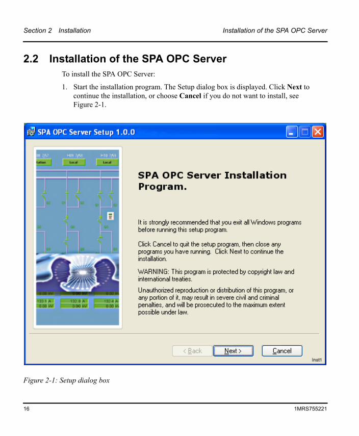
Section 2 Installation Installation of the SPA OPC Server
2.2 Installation of the SPA OPC ServerTo install the SPA OPC Server:
1. Start the installation program. The Setup dialog box is displayed. Click Next to continue the installation, or choose Cancel if you do not want to install, see Figure 2-1.
Figure 2-1: Setup dialog box
16 1MRS755221
Installation of the SPA OPC Server Section 2 Installation
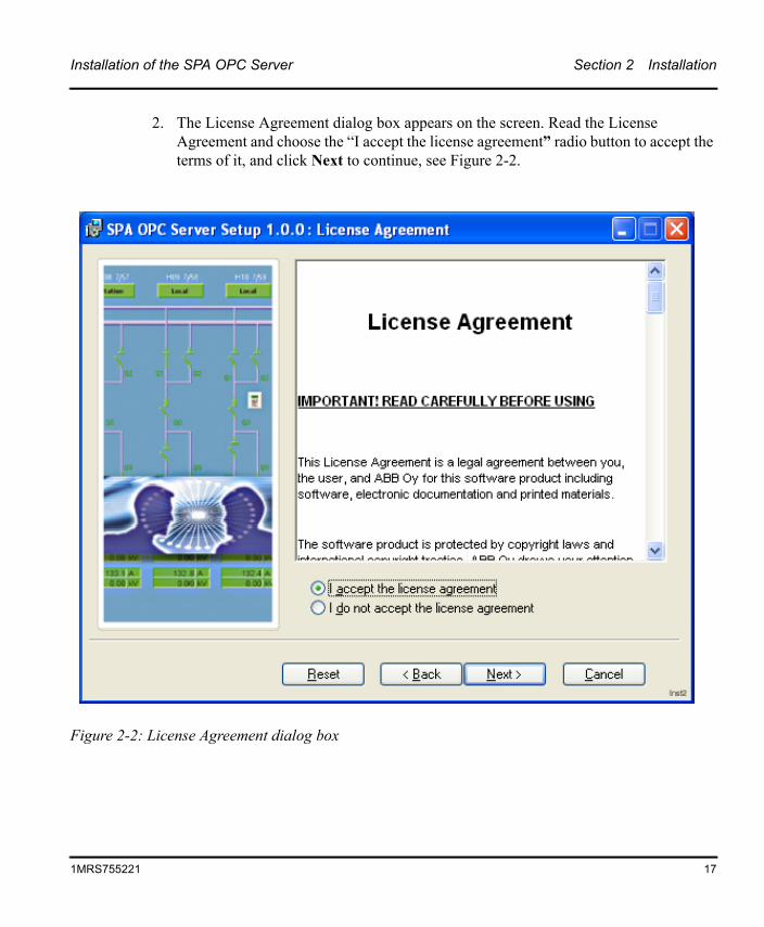
2. The License Agreement dialog box appears on the screen. Read the License Agreement and choose the “I accept the license agreement” radio button to accept the terms of it, and click Next to continue, see Figure 2-2.
Figure 2-2: License Agreement dialog box
1MRS755221 17
Section 2 Installation Installation of the SPA OPC Server
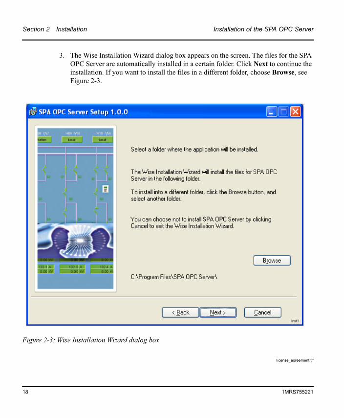
3. The Wise Installation Wizard dialog box appears on the screen. The files for the SPA OPC Server are automatically installed in a certain folder. Click Next to continue the installation. If you want to install the files in a different folder, choose Browse, see Figure 2-3.
license_agreement.tif
Figure 2-3: Wise Installation Wizard dialog box
18 1MRS755221
Installation of the SPA OPC Server Section 2 Installation
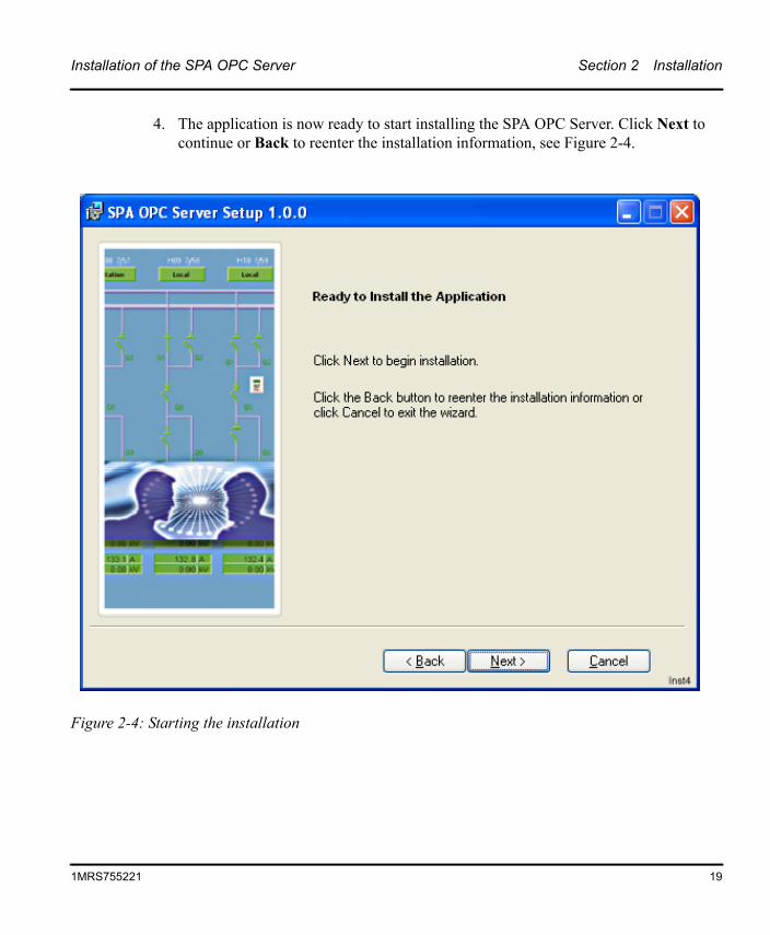
4. The application is now ready to start installing the SPA OPC Server. Click Next to continue or Back to reenter the installation information, see Figure 2-4.
Figure 2-4: Starting the installation
1MRS755221 19
Section 2 Installation Installation of the SPA OPC Server
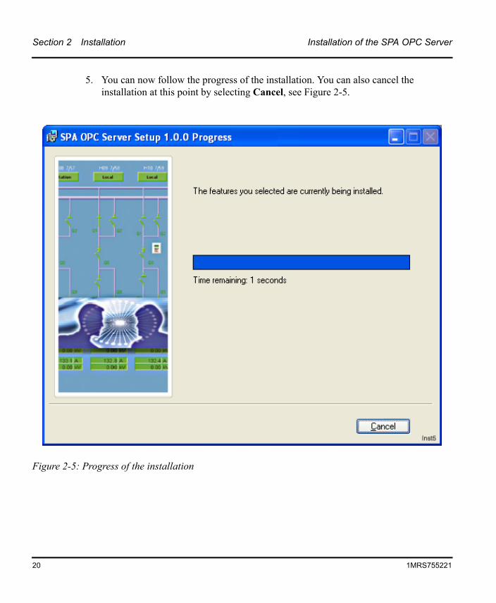
5. You can now follow the progress of the installation. You can also cancel the installation at this point by selecting Cancel, see Figure 2-5.
Figure 2-5: Progress of the installation
20 1MRS755221
Installation of the SPA OPC Server Section 2 Installation
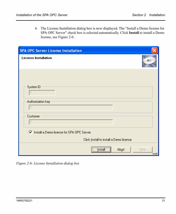
6. The License Installation dialog box is now displayed. The “Install a Demo license for SPA OPC Server” check box is selected automatically. Click Install to install a Demo license, see Figure 2-6.
Figure 2-6: License Installation dialog box
1MRS755221 21
Section 2 Installation Installation of the SPA OPC Server
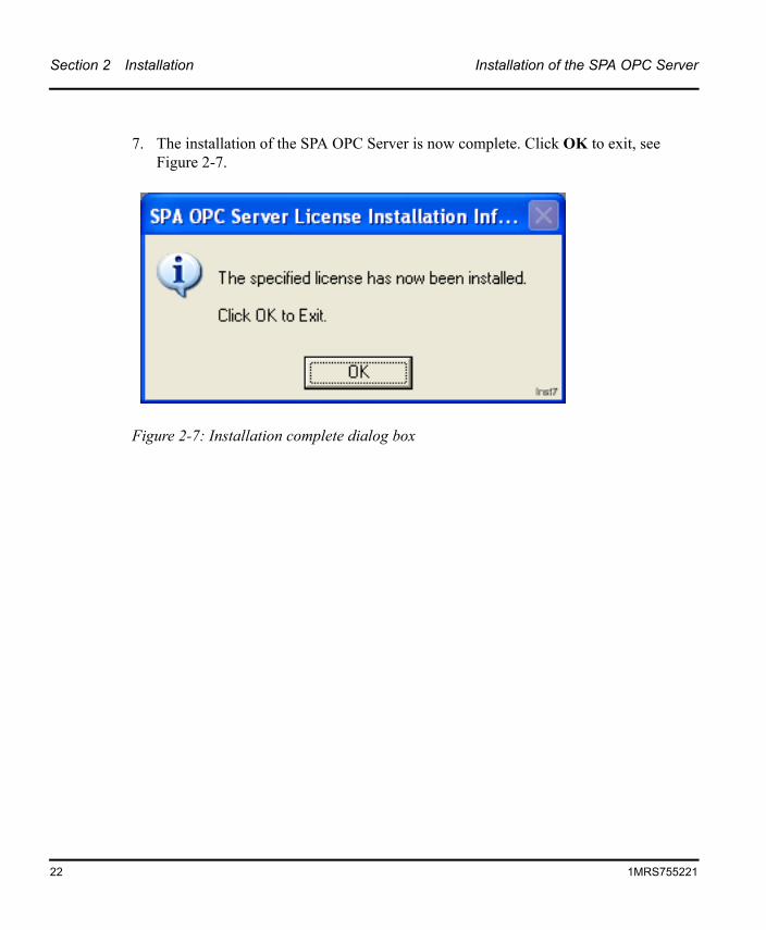
7. The installation of the SPA OPC Server is now complete. Click OK to exit, see Figure 2-7.
Figure 2-7: Installation complete dialog box
22 1MRS755221
Installation of the SPA OPC Server Section 2 Installation
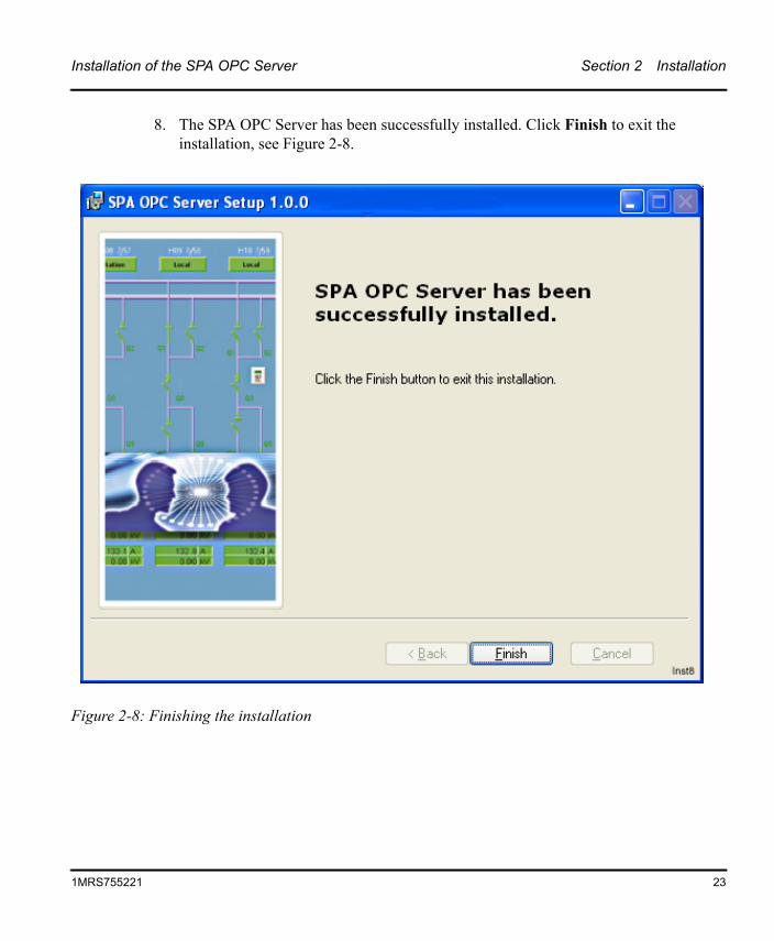
8. The SPA OPC Server has been successfully installed. Click Finish to exit the installation, see Figure 2-8.
Figure 2-8: Finishing the installation
1MRS755221 23

Section 3 Features
Section 3 Features
The purpose of this section is to describe the basic features of the SPA OPC Server. This chapter also describes concepts like OPC Data Access Namespace, Attributes and OPC Alarms and Events Area Space.
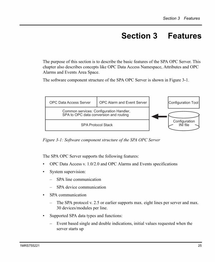
The software component structure of the SPA OPC Server is shown in Figure 3-1.
The SPA OPC Server supports the following features:
• OPC Data Access v. 1.0/2.0 and OPC Alarms and Events specifications
• System supervision:
– SPA line communication
– SPA device communication
• SPA communication
– The SPA protocol v. 2.5 or earlier supports max. eight lines per server and max. 30 devices/modules per line.
• Supported SPA data types and functions:
– Event based single and double indications, initial values requested when the server starts up
Figure 3-1: Software component structure of the SPA OPC Server
�������������� � ������� ������������ �
�������� ������������ ����������� �������������������� ��������� ������
����� ����������������� �����
�������
������� ������������������������ � ������� ������������ �
�������� ������������ ����������� �������������������� ��������� ������
����� ����������������� �����
�������
������� ����������
25
1MRS755221
Section 3 Features OPC Data Access Namespace
– Cyclically updated measurements
– Direct and secure commands
– Transparent SPA support for sending and receiving SPA messages directly from an OPC client
– Time synchronization
– Dial-up support for SPA devices connected through public telephone network
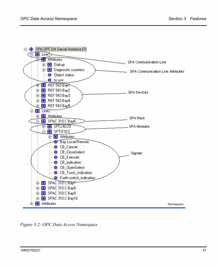
3.1 OPC Data Access NamespaceAn example of the OPC Data Access Namespace is shown in Figure 3-2. Table 3-1 describes all the components shown in Figure 3-2. Indentation is used to indicate the parent-child relationship between the nodes.
26 1MRS755221
OPC Data Access Namespace Section 3 Features
Figure 3-2: OPC Data Access Namespace
1MRS755221 27
Section 3 Features Attributes
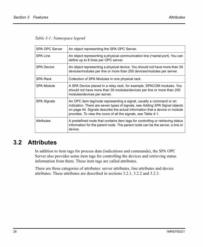
3.2 AttributesIn addition to item tags for process data (indications and commands), the SPA OPC Server also provides some item tags for controlling the devices and retrieving status information from them. These item tags are called attributes.
There are three categories of attributes: server attributes, line attributes and device attributes. These attributes are described in sections 3.2.1, 3.2.2 and 3.2.3.
Table 3-1: Namespace legend
SPA OPC Server An object representing the SPA OPC Server.SPA Line An object representing a physical communication line (=serial port). You can
define up to 8 lines per OPC server.
SPA Device An object representing a physical device. You should not have more than 30 devices/modules per line or more than 200 devices/modules per server.
SPA Rack Collection of SPA Modules in one physical rack.
SPA Module A SPA Device placed in a relay rack, for example, SPACOM modules. You should not have more than 30 modules/devices per line or more than 200 modules/devices per server.
SPA Signals An OPC item tag/node representing a signal, usually a command or an indication. There are seven types of signals, see Adding SPA Signal objects on page 44. Signals describe the actual information that a device or module provides. To view the icons of all the signals, see Table 4-1.
Attributes A predefined node that contains item tags for controlling or retrieving status information for the parent node. The parent node can be the server, a line or device.
28 1MRS755221
Attributes Section 3 Features
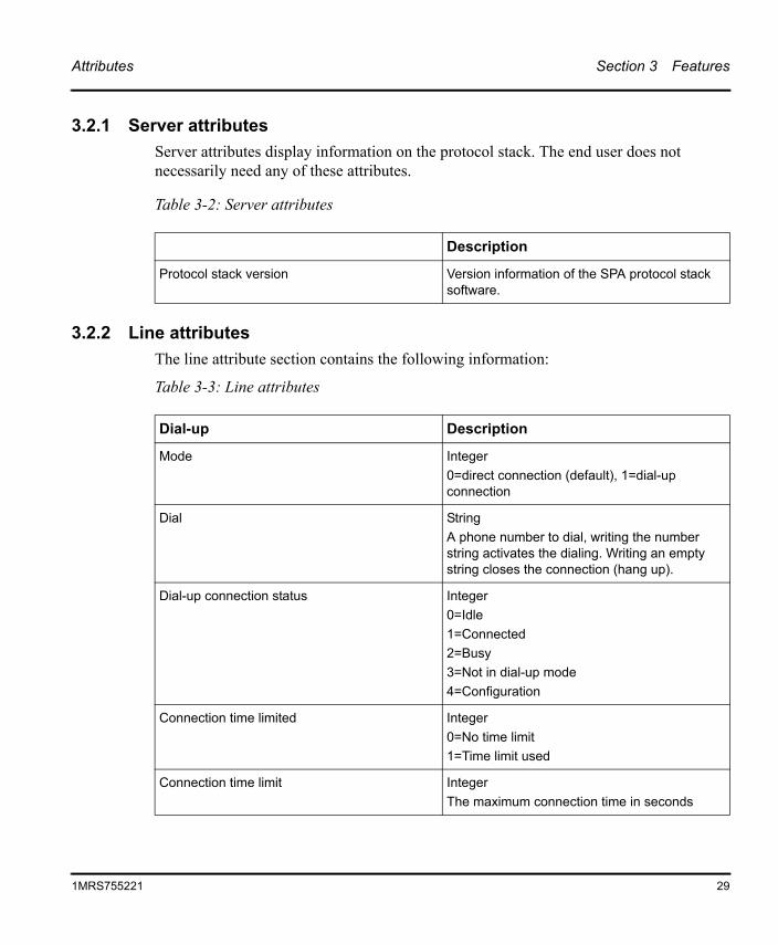
3.2.1 Server attributesServer attributes display information on the protocol stack. The end user does not necessarily need any of these attributes.
3.2.2 Line attributesThe line attribute section contains the following information:
Table 3-3: Line attributes
Table 3-2: Server attributes
Description
Protocol stack version Version information of the SPA protocol stack software.
Dial-up Description
Mode Integer0=direct connection (default), 1=dial-up connection
Dial StringA phone number to dial, writing the number string activates the dialing. Writing an empty string closes the connection (hang up).
Dial-up connection status Integer0=Idle1=Connected2=Busy3=Not in dial-up mode4=Configuration
Connection time limited Integer0=No time limit1=Time limit used
Connection time limit IntegerThe maximum connection time in seconds
1MRS755221 29
Section 3 Features Attributes
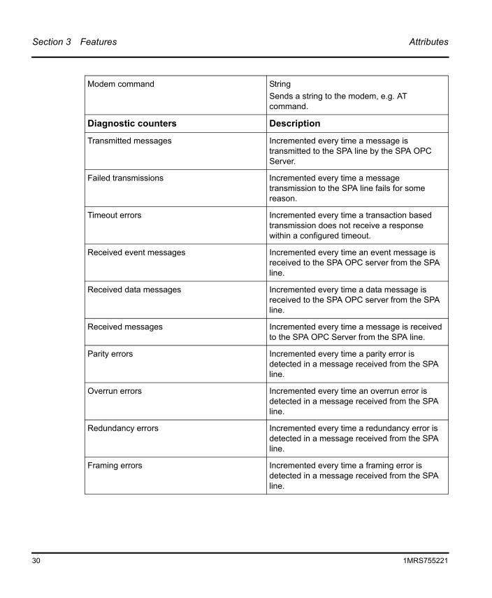
Modem command StringSends a string to the modem, e.g. AT command.
Diagnostic counters Description
Transmitted messages Incremented every time a message is transmitted to the SPA line by the SPA OPC Server.
Failed transmissions Incremented every time a message transmission to the SPA line fails for some reason.
Timeout errors Incremented every time a transaction based transmission does not receive a response within a configured timeout.
Received event messages Incremented every time an event message is received to the SPA OPC server from the SPA line.
Received data messages Incremented every time a data message is received to the SPA OPC server from the SPA line.
Received messages Incremented every time a message is received to the SPA OPC Server from the SPA line.
Parity errors Incremented every time a parity error is detected in a message received from the SPA line.
Overrun errors Incremented every time an overrun error is detected in a message received from the SPA line.
Redundancy errors Incremented every time a redundancy error is detected in a message received from the SPA line.
Framing errors Incremented every time a framing error is detected in a message received from the SPA line.
30 1MRS755221
Attributes Section 3 Features
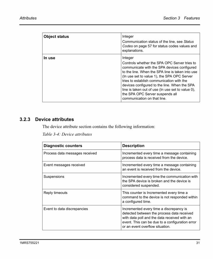
3.2.3 Device attributesThe device attribute section contains the following information:
Table 3-4: Device attributes
Object status IntegerCommunication status of the line, see Status Codes on page 57 for status codes values and explanations.
In use IntegerControls whether the SPA OPC Server tries to communicate with the SPA devices configured to the line. When the SPA line is taken into use (In use set to value 1), the SPA OPC Server tries to establish communication with the devices configured to the line. When the SPA line is taken out of use (In use set to value 0), the SPA OPC Server suspends all communication on that line.
Diagnostic counters Description
Process data messages received Incremented every time a message containing process data is received from the device.
Event messages received Incremented every time a message containing an event is received from the device.
Suspensions Incremented every time the communication with the SPA device is broken and the device is considered suspended.
Reply timeouts This counter is Incremented every time a command to the device is not responded within a configured time.
Event to data discrepancies Incremented every time a discrepancy is detected between the process data received with data poll and the data received with an event. This can be due to a configuration error or an event overflow situation.
1MRS755221 31
Section 3 Features OPC Alarms and Events Area Space
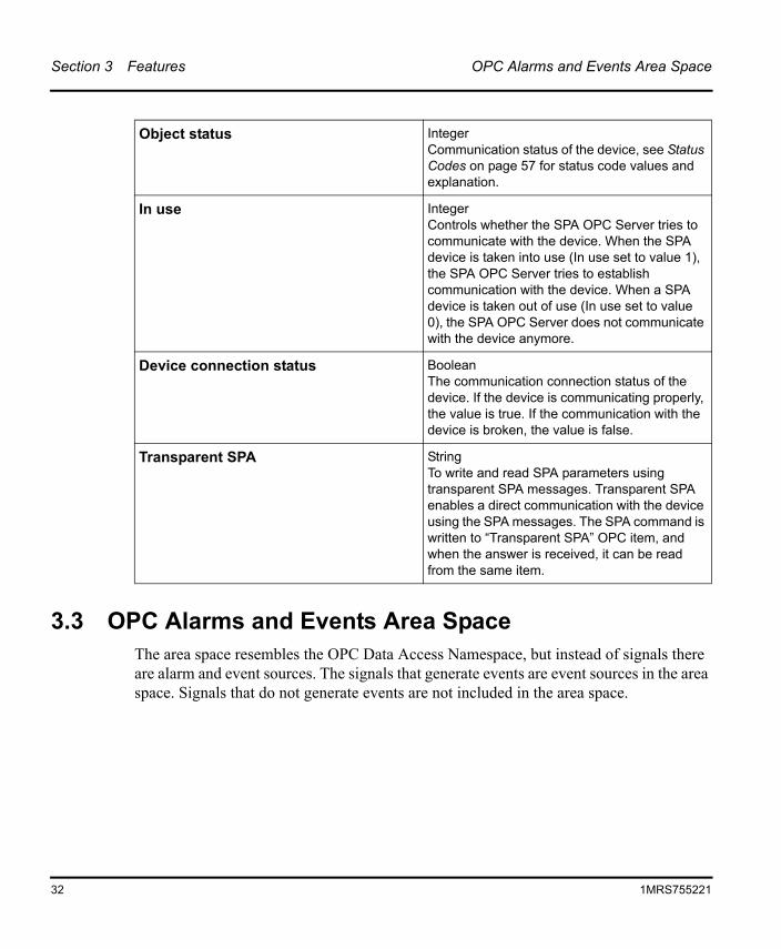
3.3 OPC Alarms and Events Area SpaceThe area space resembles the OPC Data Access Namespace, but instead of signals there are alarm and event sources. The signals that generate events are event sources in the area space. Signals that do not generate events are not included in the area space.
Object status IntegerCommunication status of the device, see Status Codes on page 57 for status code values and explanation.
In use IntegerControls whether the SPA OPC Server tries to communicate with the device. When the SPA device is taken into use (In use set to value 1), the SPA OPC Server tries to establish communication with the device. When a SPA device is taken out of use (In use set to value 0), the SPA OPC Server does not communicate with the device anymore.
Device connection status BooleanThe communication connection status of the device. If the device is communicating properly, the value is true. If the communication with the device is broken, the value is false.
Transparent SPA StringTo write and read SPA parameters using transparent SPA messages. Transparent SPA enables a direct communication with the device using the SPA messages. The SPA command is written to “Transparent SPA” OPC item, and when the answer is received, it can be read from the same item.
32 1MRS755221
OPC Alarms and Events Area Space Section 3 Features
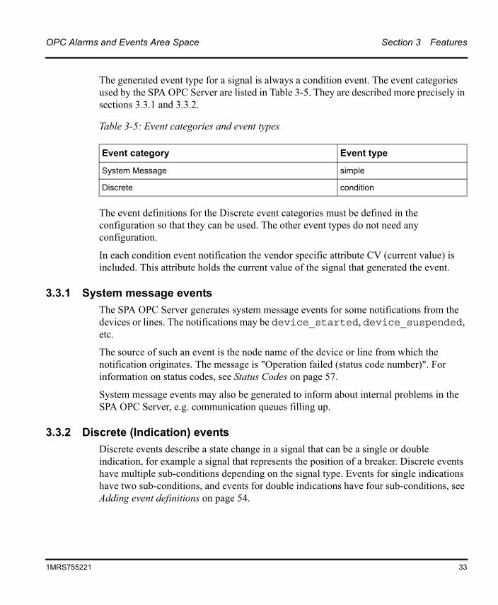
The generated event type for a signal is always a condition event. The event categories used by the SPA OPC Server are listed in Table 3-5. They are described more precisely in sections 3.3.1 and 3.3.2.
The event definitions for the Discrete event categories must be defined in the configuration so that they can be used. The other event types do not need any configuration.
In each condition event notification the vendor specific attribute CV (current value) is included. This attribute holds the current value of the signal that generated the event.
3.3.1 System message eventsThe SPA OPC Server generates system message events for some notifications from the devices or lines. The notifications may be device_started, device_suspended, etc.
The source of such an event is the node name of the device or line from which the notification originates. The message is "Operation failed (status code number)". For information on status codes, see Status Codes on page 57.
System message events may also be generated to inform about internal problems in the SPA OPC Server, e.g. communication queues filling up.
3.3.2 Discrete (Indication) eventsDiscrete events describe a state change in a signal that can be a single or double indication, for example a signal that represents the position of a breaker. Discrete events have multiple sub-conditions depending on the signal type. Events for single indications have two sub-conditions, and events for double indications have four sub-conditions, see Adding event definitions on page 54.
Table 3-5: Event categories and event types
Event category Event type
System Message simple
Discrete condition
1MRS755221 33

About this section Section 4 Engineering
Section 4 Engineering
4.1 About this sectionThis section guides you to the engineering tasks that are required before you can start using the SPA OPC Server.
To start the SPA OPC Server configuration tool, select Start > Programs > SPA OPC Server > SPA OPC Server Configuration Tool. The Figure 4-1 shows how the configuration tool looks like at this point.
35
1MRS755221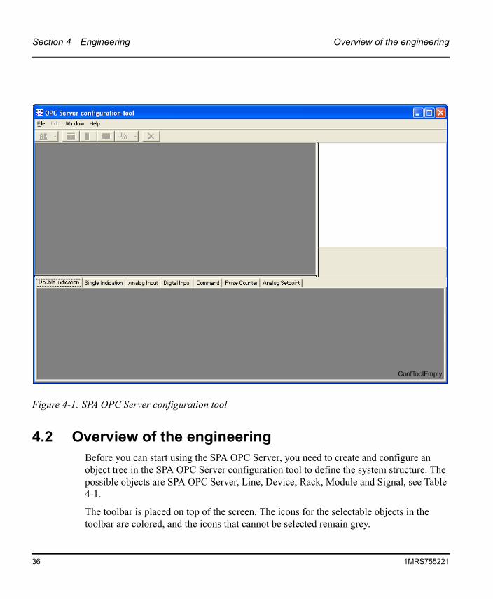
Section 4 Engineering Overview of the engineering
4.2 Overview of the engineeringBefore you can start using the SPA OPC Server, you need to create and configure an object tree in the SPA OPC Server configuration tool to define the system structure. The possible objects are SPA OPC Server, Line, Device, Rack, Module and Signal, see Table 4-1.
The toolbar is placed on top of the screen. The icons for the selectable objects in the toolbar are colored, and the icons that cannot be selected remain grey.
Figure 4-1: SPA OPC Server configuration tool
36 1MRS755221
Overview of the engineering Section 4 Engineering
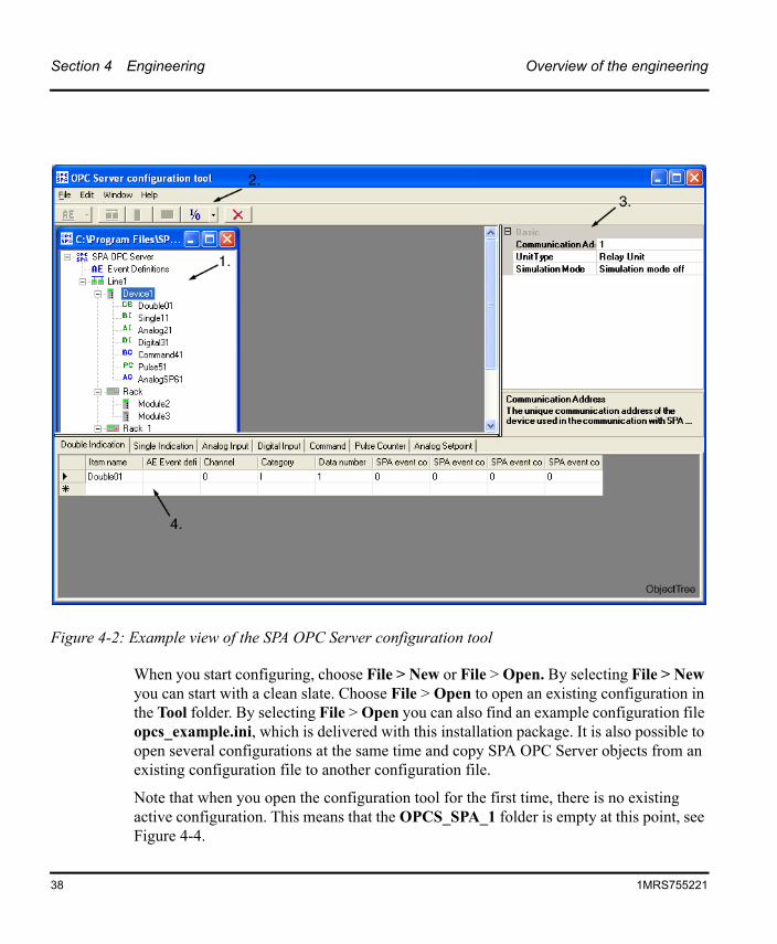
On the right side of the screen you can view the configurable properties of a chosen object. When you choose a device or module object, a table representing the configured signals appears at the bottom of the screen.
The Figure 4-2 shows an example view of the SPA OPC Server configuration tool including the following parts:
1. Object tree
2. Toolbar
3. Property grid window displaying the object properties
4. Signal table
To view the SPA OPC Server User’s Manual as a .pdf file, choose Help > Manual. To view the version of the SPA OPC Server Configuration Tool, choose Help > About.
1MRS755221 37
Section 4 Engineering Overview of the engineering
When you start configuring, choose File > New or File > Open. By selecting File > New you can start with a clean slate. Choose File > Open to open an existing configuration in the Tool folder. By selecting File > Open you can also find an example configuration file opcs_example.ini, which is delivered with this installation package. It is also possible to open several configurations at the same time and copy SPA OPC Server objects from an existing configuration file to another configuration file.
Note that when you open the configuration tool for the first time, there is no existing active configuration. This means that the OPCS_SPA_1 folder is empty at this point, see Figure 4-4.
Figure 4-2: Example view of the SPA OPC Server configuration tool
38 1MRS755221
Overview of the engineering Section 4 Engineering
The engineering work can be divided into three separate tasks:
1. creating an object tree,
2. configuring object properties, and
3. saving configuration data.
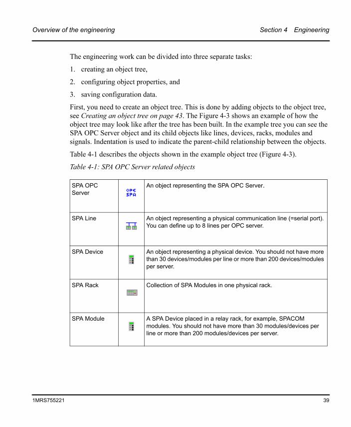
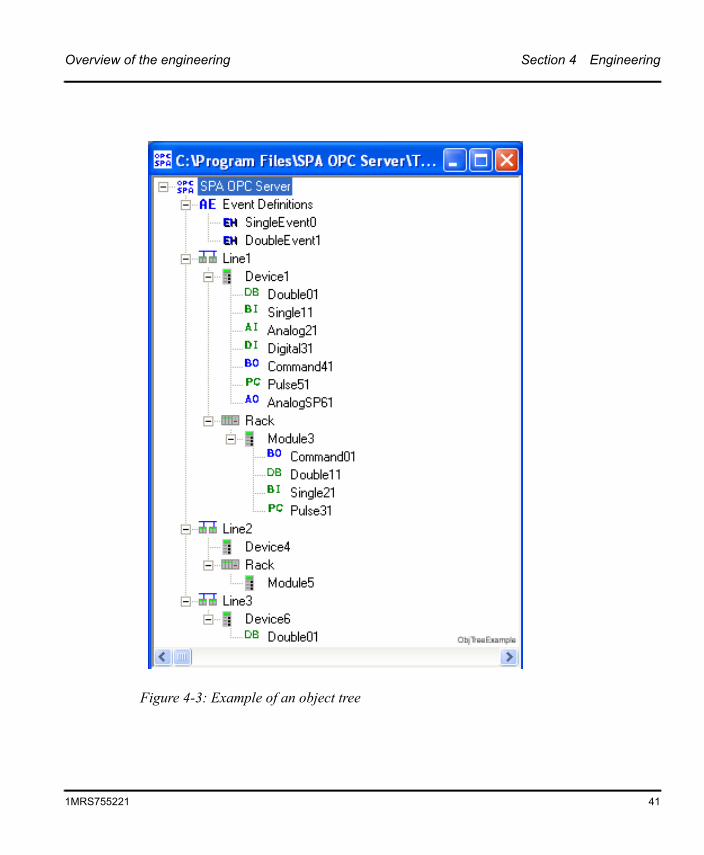
First, you need to create an object tree. This is done by adding objects to the object tree, see Creating an object tree on page 43. The Figure 4-3 shows an example of how the object tree may look like after the tree has been built. In the example tree you can see the SPA OPC Server object and its child objects like lines, devices, racks, modules and signals. Indentation is used to indicate the parent-child relationship between the objects.
Table 4-1 describes the objects shown in the example object tree (Figure 4-3).
Table 4-1: SPA OPC Server related objects
SPA OPC Server
An object representing the SPA OPC Server.
SPA Line An object representing a physical communication line (=serial port). You can define up to 8 lines per OPC server.
SPA Device An object representing a physical device. You should not have more than 30 devices/modules per line or more than 200 devices/modules per server.
SPA Rack Collection of SPA Modules in one physical rack.
SPA Module A SPA Device placed in a relay rack, for example, SPACOM modules. You should not have more than 30 modules/devices per line or more than 200 modules/devices per server.
1MRS755221 39
Section 4 Engineering Overview of the engineering
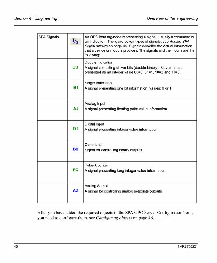
After you have added the required objects to the SPA OPC Server Configuration Tool, you need to configure them, see Configuring objects on page 46.
SPA Signals An OPC item tag/node representing a signal, usually a command or an indication. There are seven types of signals, see Adding SPA Signal objects on page 44. Signals describe the actual information that a device or module provides. The signals and their icons are the following:
Double IndicationA signal consisting of two bits (double binary). Bit values are presented as an integer value 00=0, 01=1, 10=2 and 11=3.
Single IndicationA signal presenting one bit information, values: 0 or 1.
Analog InputA signal presenting floating point value information.
Digital InputA signal presenting integer value information.
CommandSignal for controlling binary outputs.
Pulse CounterA signal presenting long integer value information.
Analog SetpointA signal for controlling analog setpoints/outputs.
40 1MRS755221
Overview of the engineering Section 4 Engineering
Figure 4-3: Example of an object tree
1MRS755221 41
Section 4 Engineering Overview of the engineering
Finally, you must save the configuration data by selecting File > Save as active configuration or File > Save as.
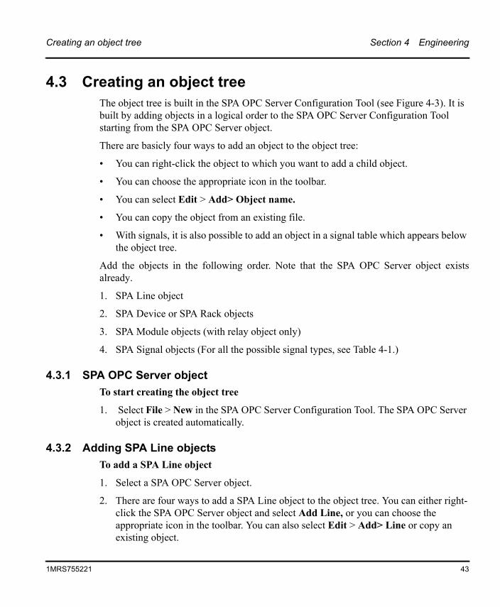
The configuration that has been saved as active in the OPC Server refers to the opcs_net.ini file saved in the OPCS_SPA_1 folder, see Figure 4-4 and Figure 4-5. When the SPA OPC Server is launched, it reads the configuration data and establishes communication with the SPA devices.
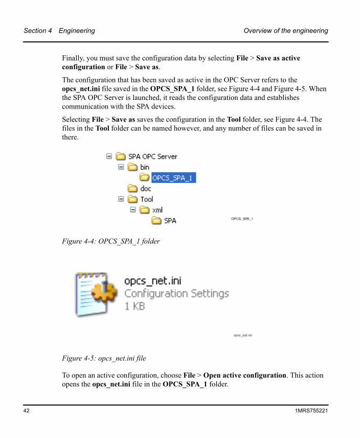
Selecting File > Save as saves the configuration in the Tool folder, see Figure 4-4. The files in the Tool folder can be named however, and any number of files can be saved in there.
To open an active configuration, choose File > Open active configuration. This action opens the opcs_net.ini file in the OPCS_SPA_1 folder.
Figure 4-4: OPCS_SPA_1 folder
Figure 4-5: opcs_net.ini file
42 1MRS755221
Creating an object tree Section 4 Engineering
4.3 Creating an object treeThe object tree is built in the SPA OPC Server Configuration Tool (see Figure 4-3). It is built by adding objects in a logical order to the SPA OPC Server Configuration Tool starting from the SPA OPC Server object.
There are basicly four ways to add an object to the object tree:
• You can right-click the object to which you want to add a child object.
• You can choose the appropriate icon in the toolbar.
• You can select Edit > Add> Object name.
• You can copy the object from an existing file.
• With signals, it is also possible to add an object in a signal table which appears below the object tree.
Add the objects in the following order. Note that the SPA OPC Server object existsalready.
1. SPA Line object
2. SPA Device or SPA Rack objects
3. SPA Module objects (with relay object only)
4. SPA Signal objects (For all the possible signal types, see Table 4-1.)
4.3.1 SPA OPC Server objectTo start creating the object tree
1. Select File > New in the SPA OPC Server Configuration Tool. The SPA OPC Server object is created automatically.
4.3.2 Adding SPA Line objectsTo add a SPA Line object
1. Select a SPA OPC Server object.
2. There are four ways to add a SPA Line object to the object tree. You can either right-click the SPA OPC Server object and select Add Line, or you can choose the appropriate icon in the toolbar. You can also select Edit > Add> Line or copy an existing object.
1MRS755221 43
Section 4 Engineering Creating an object tree
3. Rename the Line object. Note that the names of the lines have to be unique.
4.3.3 Adding SPA Device or SPA Rack objectsTo add a SPA Device or SPA Rack object
1. Select a Line object.
2. There are four ways to add a SPA Device or SPA Rack object to the object tree:
• You can right-click the Line object and select Add Device or Add Rack.
• You can choose the appropriate icon in the toolbar.
• You can select Edit > Add> Device/Rack
• You can copy an existing object.
3. Rename the Device or Rack object. Note that the names of the devices and racks within a line have to be unique.
4.3.4 Adding SPA Module objectsTo add a SPA Module object
1. Select a Rack object.
2. There are four ways to add a SPA Module object to the object tree:
• You can right-click the Rack object and select Add Module.
• You can choose the appropriate icon in the toolbar.
• You can select Edit > Add> Module.
• You can copy an existing object.
3. Rename the Module object. Note that the names of the modules within a rack have to be unique.
4.3.5 Adding SPA Signal objectsTo add a SPA Signal object
1. Select a Device or Module object.
2. There are five ways to add a SPA Signal object to the object tree:
44 1MRS755221
Creating an object tree Section 4 Engineering
• You can right-click the Device or Module object and select the Signal object you want to add, e.g. Add Double Indication.
• You can choose the appropriate icon in the toolbar.
• You can also select Edit > Add> Signal object.
• You can copy an existing object.
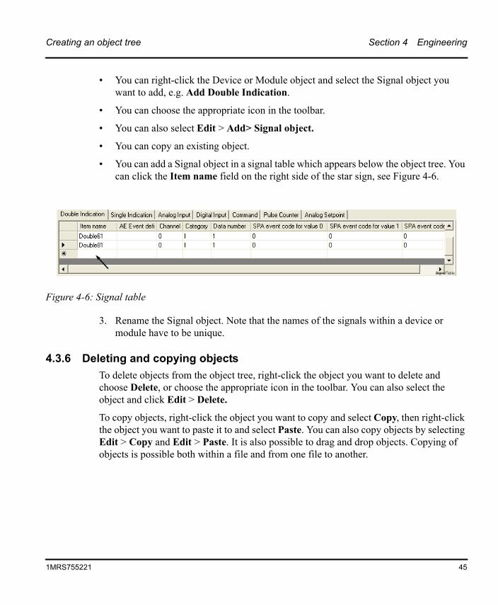
• You can add a Signal object in a signal table which appears below the object tree. You can click the Item name field on the right side of the star sign, see Figure 4-6.
3. Rename the Signal object. Note that the names of the signals within a device or module have to be unique.
4.3.6 Deleting and copying objectsTo delete objects from the object tree, right-click the object you want to delete and choose Delete, or choose the appropriate icon in the toolbar. You can also select the object and click Edit > Delete.
To copy objects, right-click the object you want to copy and select Copy, then right-click the object you want to paste it to and select Paste. You can also copy objects by selecting Edit > Copy and Edit > Paste. It is also possible to drag and drop objects. Copying of objects is possible both within a file and from one file to another.
Figure 4-6: Signal table
1MRS755221 45
Section 4 Engineering Configuring objects
4.4 Configuring objectsAfter the objects have been added, you need to configure the object properties. Nearly every object has configurable properties. In addition to the property grid window, signal properties can be modified also in the signal table, see Figure 4-6.
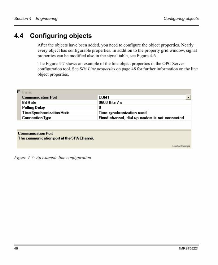
The Figure 4-7 shows an example of the line object properties in the OPC Server configuration tool. See SPA Line properties on page 48 for further information on the line object properties.
Figure 4-7: An example line configuration
46 1MRS755221
Configuring objects Section 4 Engineering
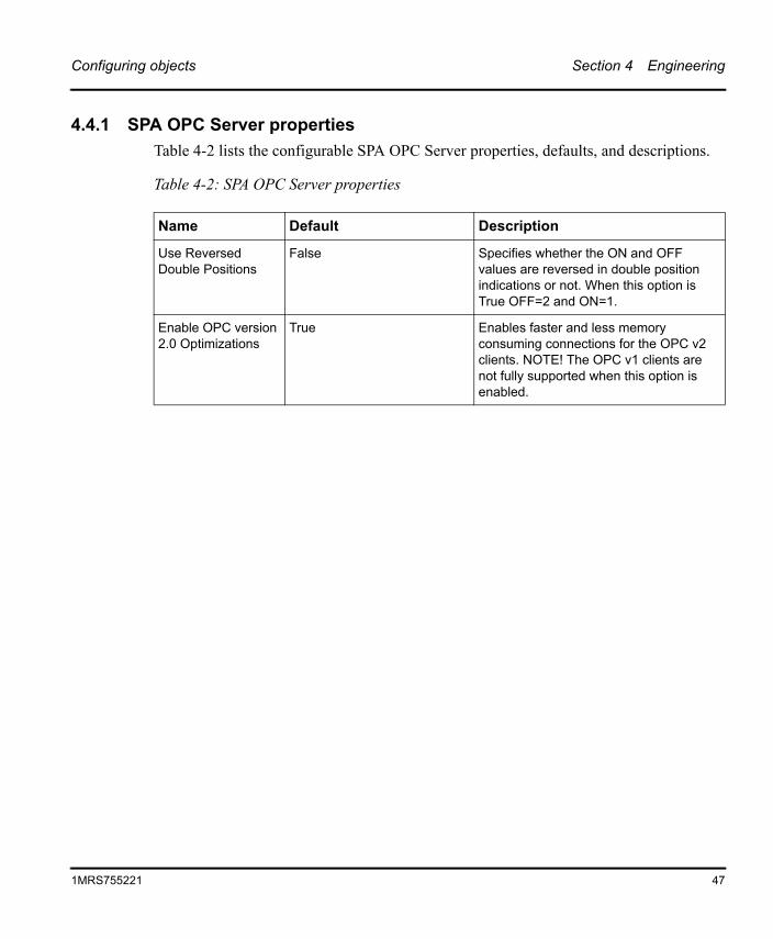
4.4.1 SPA OPC Server propertiesTable 4-2 lists the configurable SPA OPC Server properties, defaults, and descriptions.
Table 4-2: SPA OPC Server properties
Name Default Description
Use Reversed Double Positions
False Specifies whether the ON and OFF values are reversed in double position indications or not. When this option is True OFF=2 and ON=1.
Enable OPC version 2.0 Optimizations
True Enables faster and less memory consuming connections for the OPC v2 clients. NOTE! The OPC v1 clients are not fully supported when this option is enabled.
1MRS755221 47
Section 4 Engineering Configuring objects
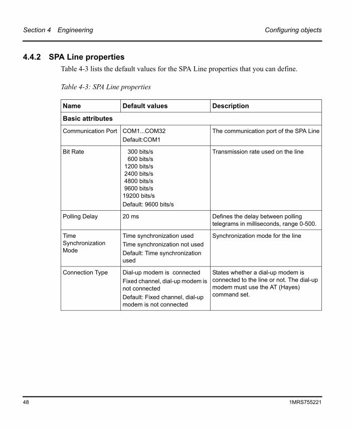
4.4.2 SPA Line propertiesTable 4-3 lists the default values for the SPA Line properties that you can define.
Table 4-3: SPA Line properties
Name Default values Description
Basic attributes
Communication Port COM1...COM32Default:COM1
The communication port of the SPA Line
Bit Rate 300 bits/s600 bits/s
1200 bits/s2400 bits/s4800 bits/s9600 bits/s
19200 bits/sDefault: 9600 bits/s
Transmission rate used on the line
Polling Delay 20 ms Defines the delay between polling telegrams in milliseconds, range 0-500.
Time Synchronization Mode
Time synchronization usedTime synchronization not usedDefault: Time synchronization used
Synchronization mode for the line
Connection Type Dial-up modem is connectedFixed channel, dial-up modem is not connectedDefault: Fixed channel, dial-up modem is not connected
States whether a dial-up modem is connected to the line or not. The dial-up modem must use the AT (Hayes) command set.
48 1MRS755221
Configuring objects Section 4 Engineering
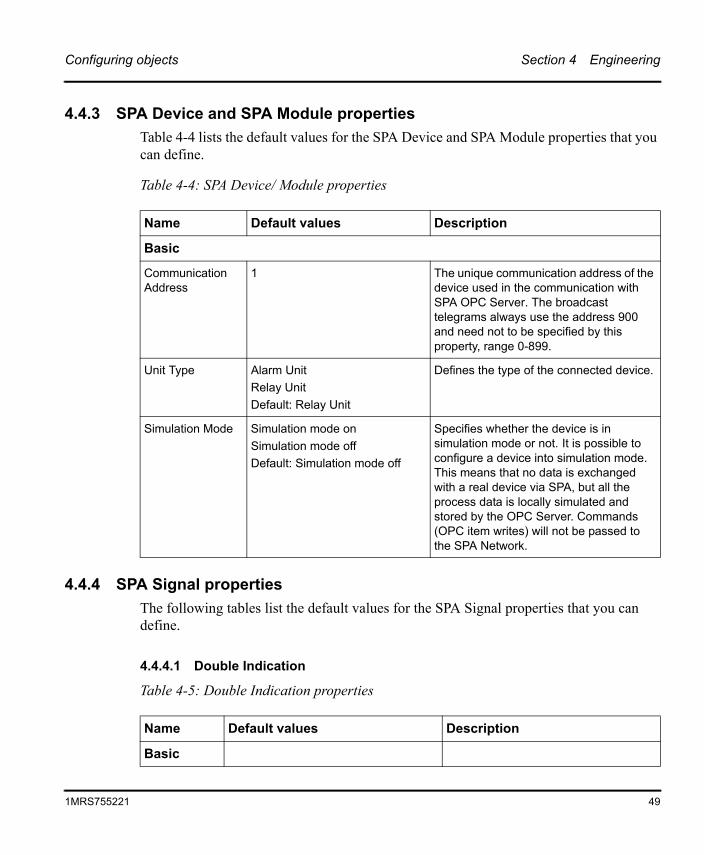
4.4.3 SPA Device and SPA Module propertiesTable 4-4 lists the default values for the SPA Device and SPA Module properties that you can define.
4.4.4 SPA Signal propertiesThe following tables list the default values for the SPA Signal properties that you can define.
4.4.4.1 Double Indication
Table 4-5: Double Indication properties
Table 4-4: SPA Device/ Module properties
Name Default values Description
Basic
Communication Address
1 The unique communication address of the device used in the communication with SPA OPC Server. The broadcast telegrams always use the address 900 and need not to be specified by this property, range 0-899.
Unit Type Alarm UnitRelay UnitDefault: Relay Unit
Defines the type of the connected device.
Simulation Mode Simulation mode onSimulation mode offDefault: Simulation mode off
Specifies whether the device is in simulation mode or not. It is possible to configure a device into simulation mode. This means that no data is exchanged with a real device via SPA, but all the process data is locally simulated and stored by the OPC Server. Commands (OPC item writes) will not be passed to the SPA Network.
Name Default values Description
Basic
1MRS755221 49
Section 4 Engineering Configuring objects
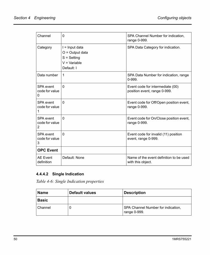
4.4.4.2 Single Indication
Table 4-6: Single Indication properties
Channel 0 SPA Channel Number for indication, range 0-999.
Category I = Input dataO = Output dataS = SettingV = VariableDefault: I
SPA Data Category for indication.
Data number 1 SPA Data Number for indication, range 0-999.
SPA event code for value 0
0 Event code for intermediate (00) position event, range 0-999.
SPA event code for value 1
0 Event code for Off/Open position event, range 0-999.
SPA event code for value 2
0 Event code for On/Close position event, range 0-999.
SPA event code for value 3
0 Event code for invalid (11) position event, range 0-999.
OPC Event
AE Event definition
Default: None Name of the event definition to be used with this object.
Name Default values Description
Basic
Channel 0 SPA Channel Number for indication, range 0-999.
50 1MRS755221
Configuring objects Section 4 Engineering
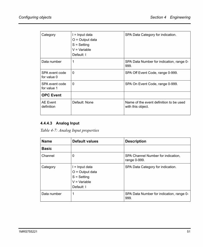
4.4.4.3 Analog Input
Table 4-7: Analog Input properties
Category I = Input dataO = Output dataS = SettingV = VariableDefault: I
SPA Data Category for indication.
Data number 1 SPA Data Number for indication, range 0-999.
SPA event code for value 0
0 SPA Off Event Code, range 0-999.
SPA event code for value 1
0 SPA On Event Code, range 0-999.
OPC Event
AE Event definition
Default: None Name of the event definition to be used with this object.
Name Default values Description
Basic
Channel 0 SPA Channel Number for indication, range 0-999.
Category I = Input dataO = Output dataS = SettingV = VariableDefault: I
SPA Data Category for indication.
Data number 1 SPA Data Number for indication, range 0-999.
1MRS755221 51
Section 4 Engineering Configuring objects
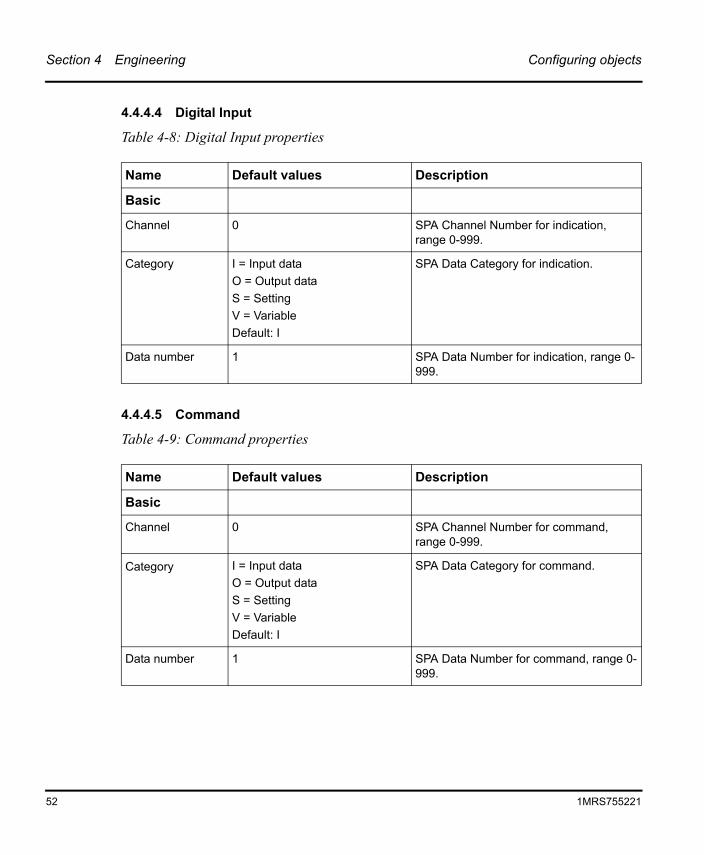
4.4.4.4 Digital Input
Table 4-8: Digital Input properties
4.4.4.5 Command
Table 4-9: Command properties
Name Default values Description
Basic
Channel 0 SPA Channel Number for indication, range 0-999.
Category I = Input dataO = Output dataS = SettingV = VariableDefault: I
SPA Data Category for indication.
Data number 1 SPA Data Number for indication, range 0-999.
Name Default values Description
Basic
Channel 0 SPA Channel Number for command, range 0-999.
Category I = Input dataO = Output dataS = SettingV = VariableDefault: I
SPA Data Category for command.
Data number 1 SPA Data Number for command, range 0-999.
52 1MRS755221
Configuring objects Section 4 Engineering
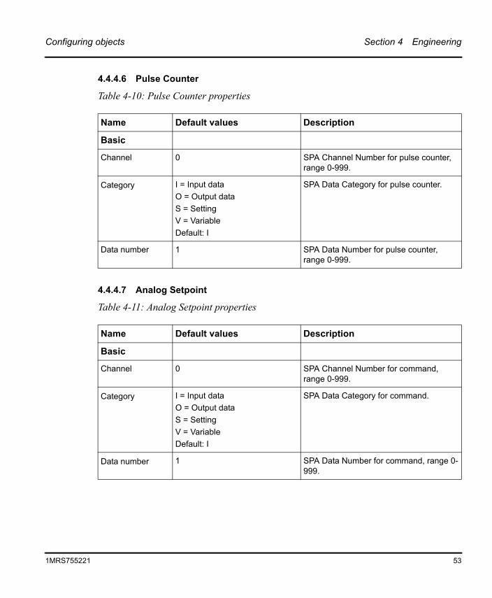
4.4.4.6 Pulse Counter
Table 4-10: Pulse Counter properties
4.4.4.7 Analog Setpoint
Table 4-11: Analog Setpoint properties
Name Default values Description
Basic
Channel 0 SPA Channel Number for pulse counter, range 0-999.
Category I = Input dataO = Output dataS = SettingV = VariableDefault: I
SPA Data Category for pulse counter.
Data number 1 SPA Data Number for pulse counter, range 0-999.
Name Default values Description
Basic
Channel 0 SPA Channel Number for command, range 0-999.
Category I = Input dataO = Output dataS = SettingV = VariableDefault: I
SPA Data Category for command.
Data number 1 SPA Data Number for command, range 0-999.
1MRS755221 53
Section 4 Engineering Adding event definitions
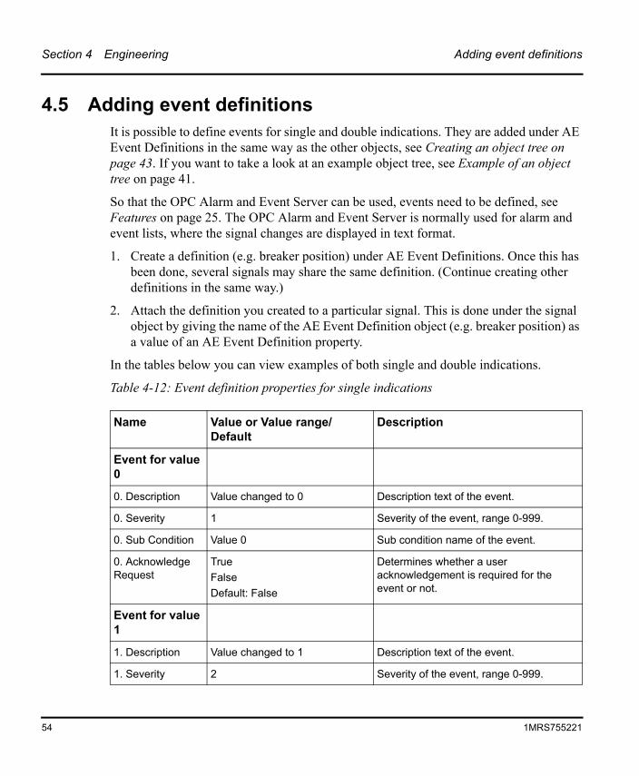
4.5 Adding event definitionsIt is possible to define events for single and double indications. They are added under AE Event Definitions in the same way as the other objects, see Creating an object tree on page 43. If you want to take a look at an example object tree, see Example of an object tree on page 41.
So that the OPC Alarm and Event Server can be used, events need to be defined, see Features on page 25. The OPC Alarm and Event Server is normally used for alarm and event lists, where the signal changes are displayed in text format.
1. Create a definition (e.g. breaker position) under AE Event Definitions. Once this has been done, several signals may share the same definition. (Continue creating other definitions in the same way.)
2. Attach the definition you created to a particular signal. This is done under the signal object by giving the name of the AE Event Definition object (e.g. breaker position) as a value of an AE Event Definition property.
In the tables below you can view examples of both single and double indications.
Table 4-12: Event definition properties for single indications
Name Value or Value range/ Default
Description
Event for value 0
0. Description Value changed to 0 Description text of the event.
0. Severity 1 Severity of the event, range 0-999.
0. Sub Condition Value 0 Sub condition name of the event.
0. Acknowledge Request
TrueFalseDefault: False
Determines whether a user acknowledgement is required for the event or not.
Event for value 1
1. Description Value changed to 1 Description text of the event.
1. Severity 2 Severity of the event, range 0-999.
54 1MRS755221
Adding event definitions Section 4 Engineering
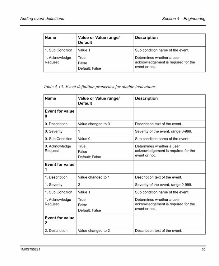
Table 4-13: Event definition properties for double indications
1. Sub Condition Value 1 Sub condition name of the event.
1. Acknowledge Request
TrueFalseDefault: False
Determines whether a user acknowledgement is required for the event or not.
Name Value or Value range/ Default
Description
Event for value 0
0. Description Value changed to 0 Description text of the event.
0. Severity 1 Severity of the event, range 0-999.
0. Sub Condition Value 0 Sub condition name of the event.
0. Acknowledge Request
TrueFalseDefault: False
Determines whether a user acknowledgement is required for the event or not.
Event for value 1
1. Description Value changed to 1 Description text of the event.
1. Severity 2 Severity of the event, range 0-999.
1. Sub Condition Value 1 Sub condition name of the event.
1. Acknowledge Request
TrueFalseDefault: False
Determines whether a user acknowledgement is required for the event or not.
Event for value 2
2. Description Value changed to 2 Description text of the event.
Name Value or Value range/ Default
Description
1MRS755221 55
Section 4 Engineering Adding event definitions
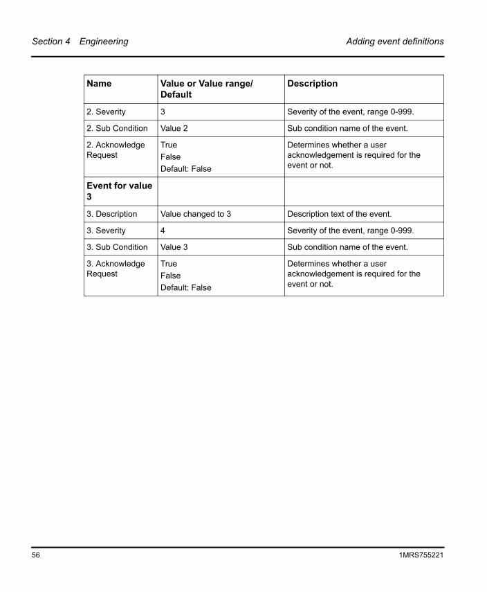
2. Severity 3 Severity of the event, range 0-999.
2. Sub Condition Value 2 Sub condition name of the event.
2. Acknowledge Request
TrueFalseDefault: False
Determines whether a user acknowledgement is required for the event or not.
Event for value 3
3. Description Value changed to 3 Description text of the event.
3. Severity 4 Severity of the event, range 0-999.
3. Sub Condition Value 3 Sub condition name of the event.
3. Acknowledge Request
TrueFalseDefault: False
Determines whether a user acknowledgement is required for the event or not.
Name Value or Value range/ Default
Description
56 1MRS755221

Appendix A Status Codes
Status codes
13201 Data overflow error
13202 Received reply length exceeds the allowed maximum length
13212 Unexpected response
13223 Unexpected value type
13225 Only write allowed
13226 No acknowledge reply
13227 Data discrepancy detected between data and event poll
13228 No transparent SPA reply available
13229 Out of buffers error
13251 Device suspended
13252 Device taken out of use
13253 Device taken into use
13254 Out of memory error
13255 Timeout while waiting response
13258 General interrogation finished
17201 Timeout while waiting CTS signal
17202 CTS signal inactivated during transmission
17203 Redundancy error in response
17204 Timeout while waiting response
17205 CTS signal continuously inactive
17206 Dial-up connection inactive
17207 Dial-up connection hang-up
57
1MRS755221
Appendix B DCOM configuration
By default, the OPC Server is installed and used as a local server, i.e. both the server and the client run on the same computer. The server can also be run as a remote server on another computer than the client. The remote server is accessed in the same way as the local server (except that the computer where the server runs must be selected in the OPC client; how this is done is client-specific), but some DCOM configuration must be performed before accessing the remote server. The DCOM configuration must be done on both the server and the client computer.
The server must be installed and registered on the server computer. It must also be registered on the client computer unless the client uses the OPC Server Browser (OPCENUM.EXE) provided by the OPC Foundation, or unless the client can browse the registry on the server computer. The registration is done automatically during the installation. Therefore it may be easiest to install the server also on the client computer, if the client requires local registry entries for the server.
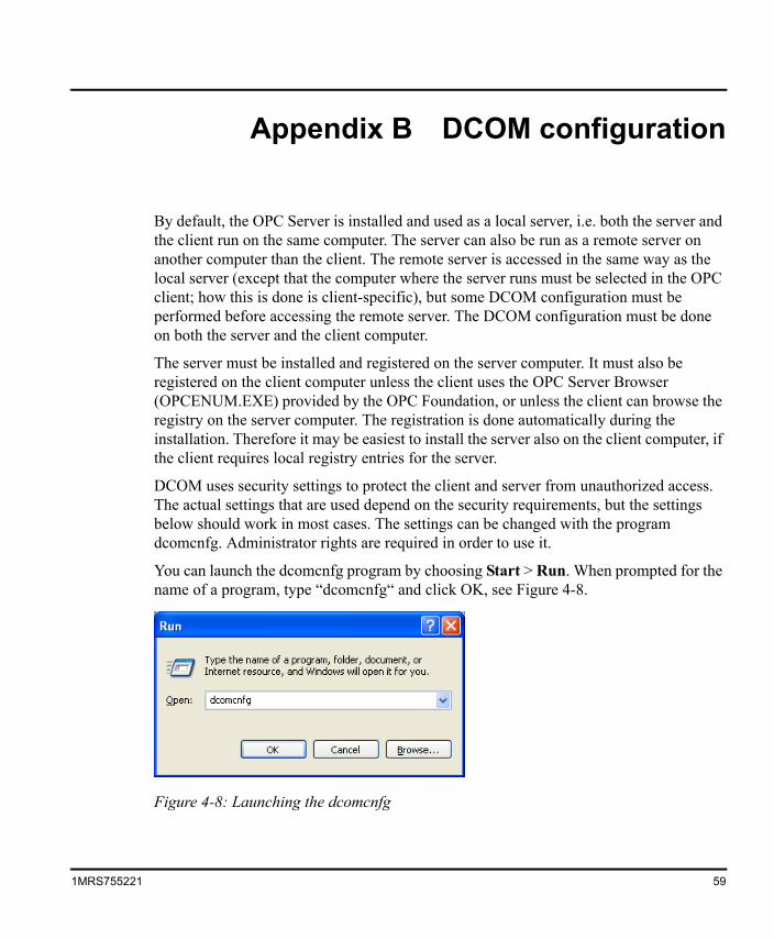
DCOM uses security settings to protect the client and server from unauthorized access. The actual settings that are used depend on the security requirements, but the settings below should work in most cases. The settings can be changed with the program dcomcnfg. Administrator rights are required in order to use it.
You can launch the dcomcnfg program by choosing Start > Run. When prompted for the name of a program, type “dcomcnfg“ and click OK, see Figure 4-8.
Figure 4-8: Launching the dcomcnfg
59
1MRS755221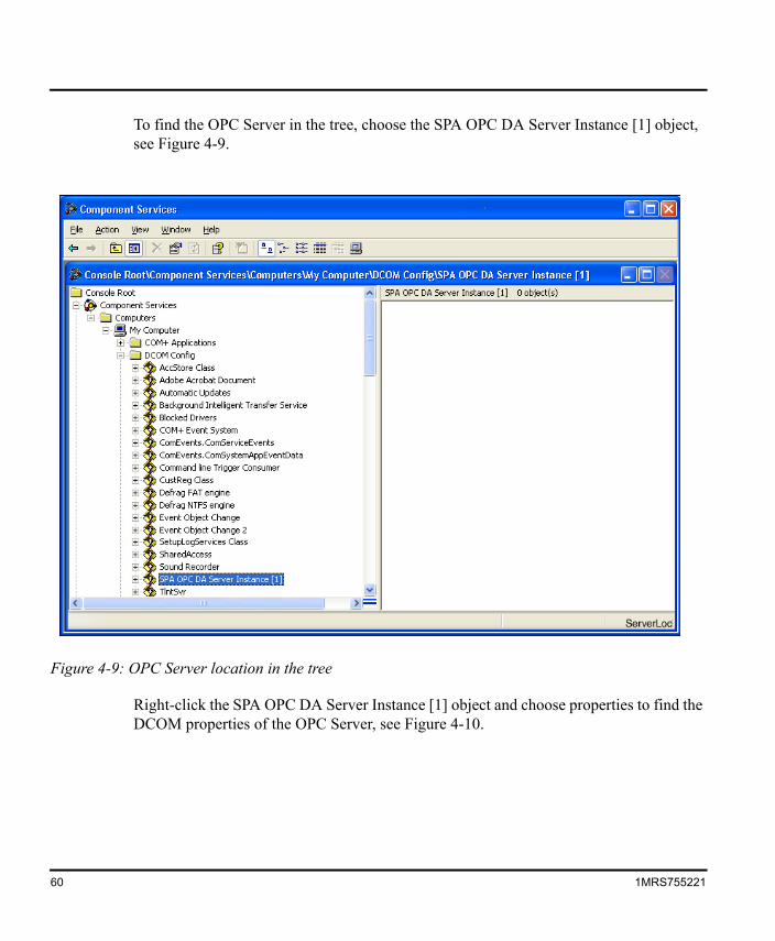
To find the OPC Server in the tree, choose the SPA OPC DA Server Instance [1] object, see Figure 4-9.
Right-click the SPA OPC DA Server Instance [1] object and choose properties to find the DCOM properties of the OPC Server, see Figure 4-10.
Figure 4-9: OPC Server location in the tree
60 1MRS755221
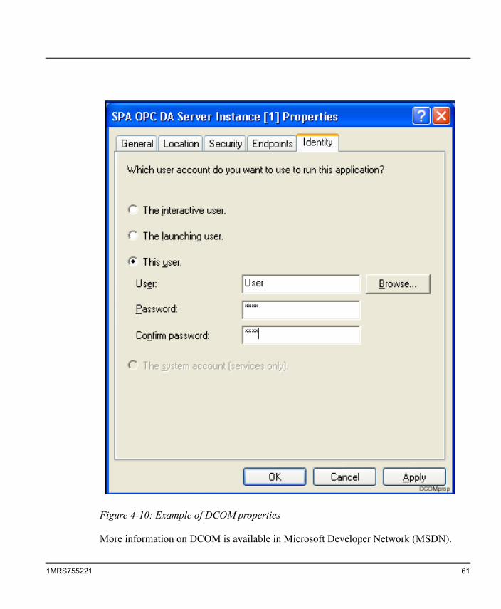
More information on DCOM is available in Microsoft Developer Network (MSDN).
Figure 4-10: Example of DCOM properties
1MRS755221 61
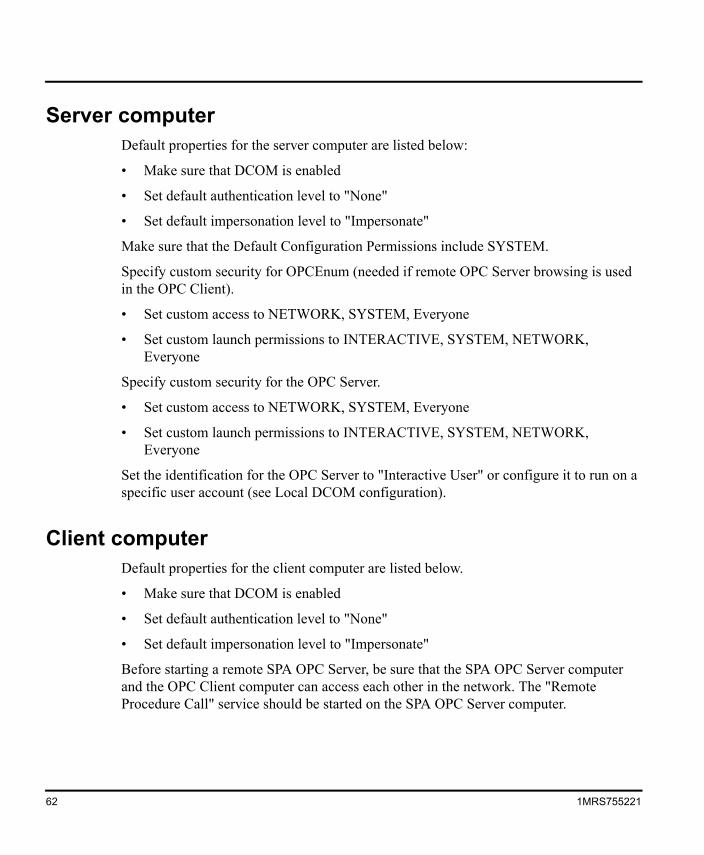
Server computerDefault properties for the server computer are listed below:
• Make sure that DCOM is enabled
• Set default authentication level to "None"
• Set default impersonation level to "Impersonate"
Make sure that the Default Configuration Permissions include SYSTEM.
Specify custom security for OPCEnum (needed if remote OPC Server browsing is used in the OPC Client).
• Set custom access to NETWORK, SYSTEM, Everyone
• Set custom launch permissions to INTERACTIVE, SYSTEM, NETWORK, Everyone
Specify custom security for the OPC Server.
• Set custom access to NETWORK, SYSTEM, Everyone
• Set custom launch permissions to INTERACTIVE, SYSTEM, NETWORK, Everyone
Set the identification for the OPC Server to "Interactive User" or configure it to run on a specific user account (see Local DCOM configuration).
Client computerDefault properties for the client computer are listed below.
• Make sure that DCOM is enabled
• Set default authentication level to "None"
• Set default impersonation level to "Impersonate"
Before starting a remote SPA OPC Server, be sure that the SPA OPC Server computer and the OPC Client computer can access each other in the network. The "Remote Procedure Call" service should be started on the SPA OPC Server computer.
62 1MRS755221
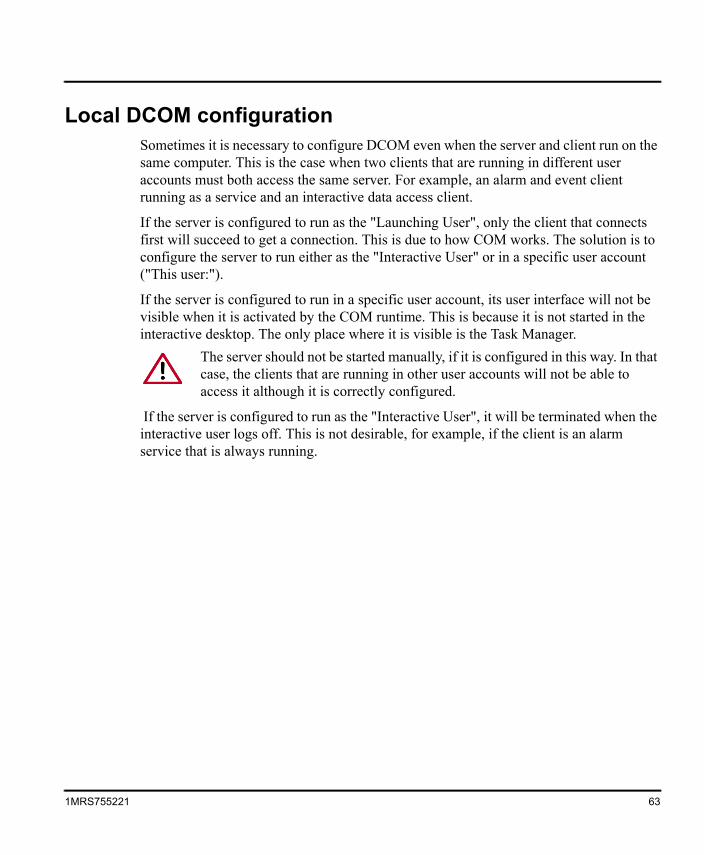
Local DCOM configurationSometimes it is necessary to configure DCOM even when the server and client run on the same computer. This is the case when two clients that are running in different user accounts must both access the same server. For example, an alarm and event client running as a service and an interactive data access client.
If the server is configured to run as the "Launching User", only the client that connects first will succeed to get a connection. This is due to how COM works. The solution is to configure the server to run either as the "Interactive User" or in a specific user account ("This user:").
If the server is configured to run in a specific user account, its user interface will not be visible when it is activated by the COM runtime. This is because it is not started in the interactive desktop. The only place where it is visible is the Task Manager.
If the server is configured to run as the "Interactive User", it will be terminated when the interactive user logs off. This is not desirable, for example, if the client is an alarm service that is always running.
The server should not be started manually, if it is configured in this way. In that case, the clients that are running in other user accounts will not be able to access it although it is correctly configured.
1MRS755221 63

AAdding objects ........................................................... 39AE ....................................................................... 10Alarms and Events (AE) ............................................ 10Analog Input ............................................................... 40Analog Setpoint ......................................................... 40Attributes .............................................................. 25, 28
Device attributes ........................................... 31Line attributes ............................................... 29Server attributes ............................................ 29
BBackup copies ........................................................... 14Basic features ............................................................ 25Bit Rate ...................................................................... 48
CCommand .................................................................. 40Communication Port .................................................. 48Configuration
Configuration tool .......................................... 35Opening an active configuration ................... 42Saving configuration data ............................. 42
ConfiguringObjects .................................................... 39, 46SPA Device properties .................................. 49SPA Line properties ...................................... 48SPA Module properties ................................. 49SPA OPC Server properties ......................... 47
Connection Type ........................................................ 48Creating
Object tree ........................................ 36, 39, 43
DDA ....................................................................... 10Data Access (DA) .................................................. 9, 10Data types and functions ........................................... 25DCOM ....................................................................... 10
Configuration ................................................. 59Device ............................................................. 9, 28, 39
Adding SPA Device objects ...........................44Device attributes .........................................................31Dial-up support ...........................................................26Digital Input .................................................................40Discrete events ...........................................................33Distributed Component Object Model (DCOM) ....10, 13Double Indication ........................................................40
EError messages ..........................................................14Events ........................................................................32
Condition event ..............................................33Discrete ..........................................................33Event categories ............................................33System Message ...........................................33
FFatal error ...................................................................14
IINI files
opcs_example.ini ...........................................38opcs_net.ini ....................................................14
Installation of the SPA OPC Server ............................16Item tags .....................................................................28
LLine ..................................................................28, 39
Adding SPA Line objects ...............................43Line attributes .............................................................29
MModule ..................................................................28, 39
Adding SPA Module objects ..........................44
NNamespace legend .....................................................28
65
1MRS755221INDEXINDEX
OObject tree .................................................................. 37
Creating an object tree .................................. 43Example of an object tree .............................. 41
Objects ................................................................. 36, 39Adding objects ......................................... 39, 43Configuring objects ........................................ 46Copying objects ............................................. 45Deleting objects ............................................. 45Object tree ..................................................... 37SPA OPC Server related objects .................. 39
OPC ....................................................................... 10Alarms and Events ........................................ 25Data Access ............................................ 13, 25
OPC Alarms and Events Area Space .................. 25, 32OPC Client ................................................................. 15OPC Clients ............................................................... 13OPC Data Access Namespace ...................... 25, 27, 32OPC item ...................................................................... 9OPC Server Browser .................................................. 59opcs_example.ini ....................................................... 38opcs_net.ini .......................................................... 14, 42OPCS_SPA_1 ...................................................... 38, 42Opening
Active configuration ....................................... 42
PPolling Delay .............................................................. 48Process data .................................................... 9, 13, 28Project specific data ................................................... 14Property grid window .................................................. 37Pulse Counter ............................................................ 40
RRack ................................................................. 28, 39
Adding SPA Rack objects ............................. 44Reinstalling the SPA OPC Server .............................. 14
SSaving
Configuration data ................................... 39, 42Server
Local ........................................................... 59Remote .......................................................... 59
Server attributes ......................................................... 29Shutting down ............................................................ 14
66
Signals ................................................................. 28, 40Adding SPA Signal objects ............................ 44Signal changes .............................................. 15Signal table .................................................... 37
Single and double indications .................................... 25Single Indication ......................................................... 40Software component structure ................................... 25SPA data types and functions .................................... 25SPA Device .............................................. 10, 13, 28, 39SPA Line .............................................................. 28, 39SPA messages
Receiving ....................................................... 26Sending ......................................................... 26Transparent SPA ........................................... 26
SPA Module ......................................................... 28, 39SPA OPC Server ........................................... 28, 35, 39
Adding SPA OPC Server object .................... 43Configuration tool .......................................... 35Objects .......................................................... 39software component structure ....................... 25
SPA OPC Server installation ..................................... 16SPA protocol .................................................. 10, 13, 25SPA Rack ............................................................. 28, 39SPA Signals ......................................................... 28, 40System message events ............................................ 33System requirements ................................................. 15System supervision .................................................... 25
TTime synchronization ................................................. 26Time Synchronization Mode ...................................... 48Toolbar ....................................................................... 37Transparent SPA ....................................................... 26
UUser account .............................................................. 63
1MRS755221


1MR
S755
221
EN 1
2.20
03
ABB OySubstation Automation P.O. Box 699FIN-65101 VAASAFinlandTel. +358 10 22 11Fax. +358 10 224 1094www.abb.com/substationautomation