Embed Size (px)
Citation preview
-- Do not store or use gasoline or other flammable vapors and liquids in the vicinity of this or any other appliance.
-- WHAT TO DO IF YOU SMELL GAS• Do not try to light any appliance.• Do not touch any electrical switch; do not use any phone in your building.• Immediately call your gas supplier from a near by phone. Follow the gas supplier’s instructions.• If you cannot reach your gas supplier, call the fire department.-- Installation and service must be performed by a qualified installer, service agency, or the gas supplier.
WARNING: If the information in these instructions is not followed exactly, a fire or explosion may result causing property damage, personal injury or death.
100280637_2000538994_Rev B
User’s Information ManualModels: 502, 752, 1002, 1302,
1501, 1701, and 2001Up To 5:1 Turndown
Beginning with Serial # 1707104971206
Save this manual for future reference.

2
Hazard definitionsThe following defined terms are used throughout this manual to bring attention to the presence of hazards of various risk levels or to important information concerning the life of the product.
� DANGER
� WARNING
� CAUTION
CAUTION
NOTICE
DANGER indicates an imminently hazardous situation which, if not avoided, will result in death or serious injury.
WARNING indicates a potentially hazardous situation which, if not avoided, could result in death or serious injury.
CAUTION indicates a potentially hazardous situation which, if not avoided, may result in minor or moderate injury.
CAUTION used without the safety alert symbol indicates a potentially hazardous situation which, if not avoided, may result in property damage.
NOTICE indicates special instructions on installation, operation, or maintenance that are important but not related to personal injury or property damage.
ContentsHAZARD DEFINITIONS ..................................................... 2PLEASE READ BEFORE PROCEEDING ......................... 31. PREVENT COMBUSTION AIR CONTAMINATION ..... 42. MAINTENANCE SCHEDULE ....................................... 5Maintenance Procedures ................................................... 6 Boiler Must Be Serviced and Maintained .................... 6 Check Boiler Area ......................................................... 6 Check Pressure Temperature Gauge ........................... 6 Check Vent Piping ........................................................ 6 Check Air Piping ........................................................... 6 Check Relief Valve ....................................................... 6 Check Condensate Drain System ................................ 6 Test Low Water Cutoff (if installed) .............................. 7 Reset Button (low water cutoff) .................................... 7 Check Boiler Piping (gas and water) ............................ 7 Operate Relief Valve .................................................... 7 Shut Boiler Down .......................................................... 7
3. OPERATING INSTRUCTIONS ..................................... 84. SMART TOUCH CON•X•US INTERFACE Power-fin CON•X•US Interface ..................................... 9 Home Screen ................................................................ 9Revision Notes ................................................... Back Cover

User’s Information Manual
Please read before proceeding
3
Installer – Read all instructions, including this manual and the Power-fin Service Manual, before installing. Perform steps in the order given.User – This manual is for use only by a qualified heating installer/service technician. Refer to the User’s Information Manual for your reference.Have this boiler serviced/inspected by a qualified service technician, at least annually.Failure to comply with the above could result in severe personal injury, death or substantial property damage.
Failure to adhere to the guidelines on this page can result in severe personal injury, death, or substantial property damage.
When servicing boiler –• To avoid electric shock, disconnect electrical supply before performing maintenance.• To avoid severe burns, allow boiler to cool before performing maintenance.
Boiler operation –• Do not block flow of combustion or ventilation air to the boiler.• Should overheating occur or gas supply fail to shut off, do not turn off or disconnect electrical supply to circulator. Instead, shut off the gas supply at a location external to the appliance.• Do not use this boiler if any part has been under water. The possible damage to a flooded appliance can be extensive and present numerous safety hazards. Any appliance that has been under water must be replaced.
Boiler water –• Thoroughly flush the system (without boiler connected) to remove sediment. The high-efficiency heat exchanger can be damaged by build-up or corrosion due to sediment.• Do not use petroleum-based cleaning or sealing compounds in the boiler system. Gaskets and seals in the system may be damaged. This can result in substantial property damage.• Do not use “homemade cures” or “boiler patent medicines”. Serious damage to the boiler, personnel, and/or property may result.• Continual fresh make-up water will reduce boiler life. Mineral buildup in the heat exchanger reduces heat transfer, overheats the heat exchanger, and causes failure. Addition of oxygen carried in by makeup water can cause internal corrosion in system components. Leaks in boiler or piping must be repaired at once to prevent the need for makeup water.
Freeze protection fluids –• NEVER use automotive antifreeze. Use only inhibited propylene glycol solutions, which are specifically formulated for hydronic systems. Ethylene glycol is toxic and can attack gaskets and seals used in hydronic systems.
When calling or writing about the boiler – Please have the boiler model and serial number from the boiler rating plate.Consider piping and installation when determining boiler location.Any claims for damage or shortage in shipment must be filed immediately against the transportation company by the consignee.Factory warranty (shipped with unit) does not apply to units improperly installed or improperly operated.
If the information in this manual is not followed exactly, a fire or explosion may result causing property damage, personal injury or loss of life.This appliance MUST NOT be installed in any location where gasoline or flammable vapors are likely to be present.
WHAT TO DO IF YOU SMELL GAS• Do not try to light any appliance.• Do not touch any electric switch; do not use any phone in your building.• Immediately call your gas supplier from a near by phone. Follow the gas supplier’s instructions.• If you cannot reach your gas supplier, call the fire department.• Installation and service must be performed by a qualified installer, service agency, or the gas supplier.
� WARNING
NOTICE
� WARNING
� WARNING
� WARNING DO NOT install units in rooms or environments that contain corrosive contaminants (see Table 1A on page 4). Failure to comply could result in severe personal injury, death, or substantial property damage.
� WARNING The California Safe Drinking Water and Toxic Enforcement Act requires the Governor of California to publish a list of substances known to the State of California to cause cancer, birth defects, or other reproductive harm, and requires businesses to warn of potential exposure to such substances.This product contains a chemical known to the State of California to cause cancer, birth defects, or orther reproductive harm. This boiler can cause low level exposure to some of the substances listed in the Act.

1 Prevent combustion air contamination
4
If the boiler combustion air inlet is located in a laundry room or pool facility, for example, these areas will always contain hazardous contaminants.
To prevent the potential of severe personal injury or death, check for areas and products listed in Table 1A before installing the boiler or air inlet piping.
If contaminants are found, you MUST: • Remove products permanently. —OR— • Relocate air inlet and vent terminations to other areas.
� WARNING
� WARNING
Products to avoid:
Spray cans containing chloro/fluorocarbons
Permanent wave solutions
Chlorinated waxes/cleaners
Chlorine-based swimming pool chemicals
Calcium chloride used for thawing
Sodium chloride used for water softening
Refrigerant leaks
Paint or varnish removers
Hydrochloric acid/muriatic acid
Cements and glues
Antistatic fabric softeners used in clothes dryers
Chlorine-type bleaches, detergents, and cleaning solvents found in household laundry roomsAdhesives used to fasten building products and other similar productsAreas likely to have contaminants
Dry cleaning/laundry areas and establishments
Swimming pools
Metal fabrication plants
Beauty shops
Refrigeration repair shops
Photo processing plants
Auto body shops
Plastic manufacturing plants
Furniture refinishing areas and establishments
New building construction
Remodeling areas
Garages with workshops
Table 1A Corrosive Contaminants and Sources� WARNING If the boiler combustion air inlet is located in any area likely to cause contamination, or if products which would contaminate the air cannot be removed, you must have the combustion air and vent re-piped and terminated to another location. Contaminated combustion air will damage the boiler, resulting in possible severe personal injury, death, or substantial property damage.
Pool and laundry products and common household and hobby products often contain fluorine or chlorine compounds. When these chemicals pass through the boiler, they can form strong acids. The acid can eat through the boiler wall, causing serious damage and presenting a possible threat of flue gas spillage or boiler water leakage into the building.
Please read the information listed in Table 1A. If contaminating chemicals will be present near the location of the boiler combustion air inlet, have your installer pipe the boiler combustion air and vent to another location, per the Power-fin Installation and Operation Manual.
User’s Information Manual
2 Maintenance schedule
5
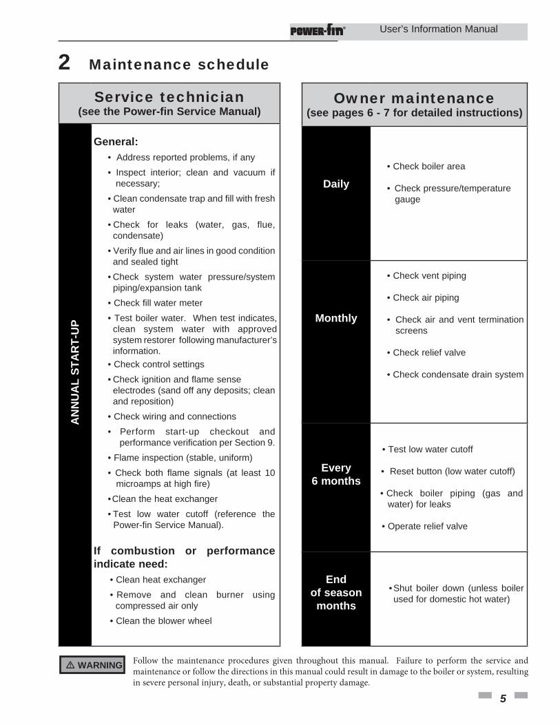
� WARNING Follow the maintenance procedures given throughout this manual. Failure to perform the service and maintenance or follow the directions in this manual could result in damage to the boiler or system, resulting in severe personal injury, death, or substantial property damage.
Service technician(see the Power-fin Service Manual)
General: • Address reported problems, if any • Inspect interior; clean and vacuum if necessary; • Clean condensate trap and fill with fresh water • Check for leaks (water, gas, flue, condensate) • Verify flue and air lines in good condition and sealed tight • Check system water pressure/system piping/expansion tank • Check fill water meter • Test boiler water. When test indicates, clean system water with approved system restorer following manufacturer’s information. • Check control settings • Check ignition and flame sense electrodes (sand off any deposits; clean and reposition) • Check wiring and connections • Perform start-up checkout and performance verification per Section 9. • Flame inspection (stable, uniform) • Check both flame signals (at least 10 microamps at high fire) • Clean the heat exchanger • Test low water cutoff (reference the Power-fin Service Manual).
If combustion or performance indicate need: • Clean heat exchanger • Remove and clean burner using compressed air only • Clean the blower wheel
AN
NU
AL
STA
RT-
UP
Owner maintenance(see pages 6 - 7 for detailed instructions)
Daily • Check boiler area
• Check pressure/temperature gauge
Monthly
• Check vent piping
• Check air piping • Check air and vent termination screens
• Check relief valve
• Check condensate drain system
Every6 months
• Test low water cutoff
• Reset button (low water cutoff) • Check boiler piping (gas and water) for leaks
• Operate relief valve
Endof season months
• Shut boiler down (unless boiler used for domestic hot water)
User’s Information Manual
6
2 Maintenance scheduleMaintenance procedures
Boiler must be serviced and maintained
� WARNING The boiler must be inspected and started annually at the beginning of the heating season by a qualified service technician. In addition, the maintenance and care of the boiler designated on page 5 of this manual and explained on pages 6 through 7 must be performed to assure maximum boiler efficiency and reliability. Failure to service and maintain the boiler and system could result in equipment failure, causing possible severe personal injury, death, or substantial property damage.
NOTICE The following information provides detailed instructions for completing the maintenance items listed in the maintenance schedule on page 5. In addition to this maintenance, the boiler must be serviced and started up at the beginning of each heating season by a qualified service technician.
Check boiler area
� WARNING To prevent potential of severe personal injury, death, or substantial property damage, eliminate all materials discussed below from the boiler vicinity and the vicinity of the boiler combustion air inlet. If contaminants are found:
Remove products immediately from the area. If they have been there for an extended period, call a qualified service technician to inspect the boiler for possible damage from acid corrosion.
If products cannot be removed, immediately call a qualified service technician to re-pipe vent and air piping and locate vent termination/air intake away from contaminated areas.
1. Combustible/flammable materials -- Do not store combustible materials, gasoline or any other flammable vapors or liquids near the boiler. Remove immediately if found.
2. Air contaminants -- Products containing chlorine or fluorine, if allowed to contaminate the boiler intake air, will cause acidic condensate in the boiler. This will cause significant damage to the boiler if allowed to continue.
Read the list of potential materials listed in Table 1A on page 4 of this manual. If any of these products are in the room from which the boiler takes its combustion air, they must be removed immediately or the boiler combustion air (and vent termination) must be relocated to another area.
Check pressure/temperature gauge
1. Make sure the pressure reading on the boiler pressure/ temperature gauge does not exceed 24 psi (165.5 kPa). Higher pressure may indicate a problem with the expansion tank.
2. Contact a qualified service technician if problem persists.
Check vent piping
1. Visually inspect the flue gas vent piping for any signs of blockage, leakage, or deterioration of the piping. Notify your qualified service technician at once if you find any problems.
� WARNING Failure to inspect the vent system as noted above and have it repaired by a qualified service technician can result in vent system failure, causing severe personal injury or death.
Check air piping1. Visually inspect the air inlet elbow to be sure it is unobstructed. Inspect the entire length of air piping to ensure piping is intact and all joints are properly sealed.2. Call your qualified service technician if you notice any problems.
Check relief valve1. Inspect the boiler relief valve and the relief valve discharge pipe for signs of weeping or leakage.2. If the relief valve often weeps, the expansion tank may not be working properly. Immediately contact your qualified service technician to inspect the boiler and system.
Check condensate drain system1. Inspect the condensate drain line, vent line, condensate PVC fittings, and condensate trap.
Flush condensate trap with water1. Remove the four (4) screws securing the top cover to the
condensate trap and remove the cover (FIG. 2-1).2. Locate the plastic ball inside the float tube. Verify there is nothing under the ball causing it to not seat properly.3. Replace the top cover and the screws removed in Step 1.
User’s Information Manual

2 Maintenance schedule (continued)
7
Figure 2-1 Condensate Trap
User’s Information Manual
� WARNING Have leaks fixed at once by a qualified service technician. Failure to comply could result in severe personal injury, death, or substantial property damage.
2. Read the boiler pressure/temperature gauge to make sure the system is pressurized. Lift the relief valve top lever slightly, allowing water to relieve through the valve and discharge piping.
3. If water flows freely, release the lever and allow the valve to seat. Watch the end of the relief valve discharge pipe to ensure that the valve does not weep after the line has had time to drain. If the valve weeps, lift the seat again to attempt to clean the valve seat. If the valve continues to weep afterwards, contact your qualified service technician to inspect the valve and system.
4. If water does not flow from the valve when you lift the lever completely, the valve or discharge line may be blocked. Immediately shut down the boiler, following the operating instructions on page 8 of this manual. Call your qualified service technician to inspect the boiler and system.
Shut boiler down (unless boiler is used for Domestic Water)
1. Follow “To Turn Off Gas to Appliance” on page 8 of this manual.
2. Do not drain the system unless exposure to freezing temperatures will occur.
3. Do not drain the system if it is filled with an antifreeze solution.
4. DO NOT shut down boilers used for domestic water heating, they must operate year-round.
3. Replace the front access door.
Test low water cutoff (if installed)
1. If the system is equipped with a low water cutoff, test the low water cutoff periodically during the heating season, following the low water cutoff manufacturer’s instructions.
Reset button (low water cutoff)
1. Testing the low water cutoff shuts the unit off. Press the RESET button on the low water cutoff to turn the unit back on.
Check boiler piping (gas and water)
1. Remove the boiler front access door and perform a gas leak inspection per steps 1 through 7 of the Operating Instructions on page 8. If gas odor or leak is detected, immediately shut down the boiler following the procedure on page 8. Call a qualified service technician.
2. Visually inspect for leaks around water piping. Also inspect the circulators, relief valve, and fittings. Immediately call a qualified service technician to repair any leaks.
Operate relief valve1. Before proceeding, verify that the relief valve outlet has been piped to a safe place of discharge, avoiding any possibility of scalding from hot water.
� WARNING To avoid water damage or scalding due to valve operation, a metal discharge line must be connected to the relief valve outlet and run to a safe place of disposal. This discharge line must be installed by a qualified heating installer or service technician in accordance with the instructions in the Power-fin Installation and Operation Manual. The discharge line must be terminated so as to eliminate possibility of severe burns or property damage should the valve discharge.

8
3 Operating instructions
User’s Information Manual
FOR YOUR SAFETY READ BEFORE OPERATINGWARNING: If you do not follow these instructions exactly, a fire or explosion may result causing property damage, personal injury, or loss of life.
A. This appliance does not have a pilot. It is equipped with an ignition device which automatically l ights the burner. Do not try to l ight the burner by hand.
B. BEFORE OPERATING smell all around the appliance area for gas. Be sure to smell next to the floor because some gas is heavier than air and will settle on the floor.
WHAT TO DO IF YOU SMELL GAS
• Do not try to light any appliance.
• Do not touch any electric switch; do not use any phone in your building.
• Immediately call your gas supplier from a neighbor’s phone. Follow the gas supplier’s instructions.
• If you cannot reach your gas supplier, call the fire department.
C. Use only your hand to turn the gas control knob. Never use tools. If the handle will not turn by hand, don’t try to repair it, call a qualified service technician. Force or attempted repair may result in a fire or explosion.
D. Do not use this appliance if any part has been under water. Immediately call a qualified service technician to inspect the appliance and to replace any part of the control system and any gas control which has been under water.
OPERATING INSTRUCTIONS 1. STOP! Read the safety information
above on this label. 2. Set the thermostat to lowest setting. 3. Turn off all electric power to the
appliance. 4. This appliance is equipped with an
ignition device which automatically lights the burner. Do not try to light the burner by hand.
5. Remove front door. 6. Turn gas shutoff valve counterclockwise
to “OFF”. Handle will be perpendicular to pipe. Do not force.
7. Wait five (5) minutes to clear out any gas. If you then smell gas, STOP! Follow “B” in the safety information above this label. If you don’t smell gas, go to next step.
8. Turn gas shutoff valve clockwise to “ON”. Handle will be parallel to pipe.
9. Install front door. 10. Turn on all electric power to appliance. 11. Set thermostat to desired setting. 12. If the appliance will not operate, follow the
instructions “To Turn Off Gas To Appliance” and call your service technician or gas supplier.
TO TURN OFF GAS TO APPLIANCE 1. Set the thermostat to lowest setting. 2. Turn off all electric power to the appliance
if service is to be performed. 3. Remove front door.
4. Turn gas shut off valve counterclockwise to “OFF”. Handle will be perpendicular to pipe. Do not force.
5. Install front door.
LBL20053 REV B

9
4 SMART TOUCH CON•X•US Interface
User’s Information Manual
Figure 4-1 Home Screen
The Home Screen displays the available basic system information. It is divided into the following sections: Status, System, Boiler, Modulation, and Navigation.
w/Power-fin CON•X•US Interface
• The System Section is located in the middle of the screen and displays exterior sensor data. If hooked up it will display the following: Outdoor Air, Hot Water Temp, System Supply Temperature, and System Return Temperature.
• The Boiler Section is located in the lower middle of the screen and displays sensor data for those sensors installed in the factory as follows: Inlet, Outlet and Delta Water Temperature, Outlet Water Temperature, Flue Temperature, Flame Currents, and Premix Air Temperatures.
• The Modulation Section is located on the right of the screen and displays the target modulation of the unit.
• The Status Section is located on the left of the screen and displays how the unit is currently running (i.e. Off, Stand- by, Blocking, and Lockout) including: the Power Button, current driving demand (i.e. Space Heat or Hot Water), the next Space Heat or Hot Water Setback scheduled, the reason for any blocking or lockout, and the current set point temperature with a button that allows you to change the set points.
• The Navigation Section is located across the top of the screen. There are three (3) main sections located next to the Lochinvar icon: Home, View, and Setup. The Home Section is the screen shown above. The View Section takes you to several screens that allows you to view sensor data. The View Screens consists of Boiler, Modulation, Pump, Cascade, BMS/BAS, Graph, History, and Service Notes. The Setup Screen has several screens to aid in setting up the boiler. The Setup Screens consist of Set Points, Rapid Setup, Advance Setup, HW Night Setback, Service Maintenance, Service Notification, and BAS. There is also a HELP button located on the right side of the screen along with an expanded HELP option (About, Save/ Load Parameters - also known as Loch-N-Link, System Update, and Wifi Setup).

10
Notes User’s Information Manual

11
Notes User’s Information Manual

Revision Notes: Revision A (Process #3000005813_Change #500005966) initial release.
Revision B (PCP # 3000021634 / CN # 500011858) reflects an update to the maintenance information for the service technician on page 5.
MM #100280637_DIR #2000538994_Rev B12/17