Embed Size (px)
Citation preview
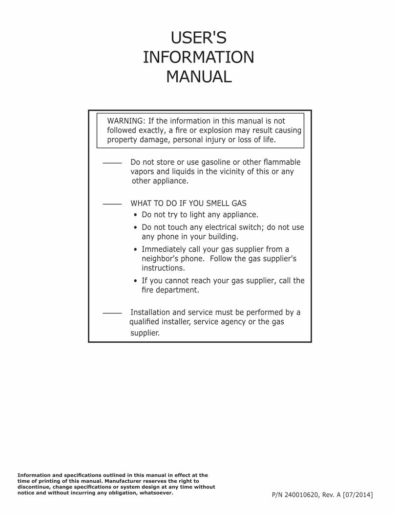
USER'S INFORMATION
MANUAL
WARNING: If the information in this manual is not followed exactly, a fire or explosion may result causing property damage, personal injury or loss of life. Do not store or use gasoline or other flammable vapors and liquids in the vicinity of this or any other appliance. WHAT TO DO IF YOU SMELL GAS
• Do not try to light any appliance.• Do not touch any electrical switch; do not use
any phone in your building.• Immediately call your gas supplier from a
neighbor's phone. Follow the gas supplier's instructions.
• If you cannot reach your gas supplier, call the fire department.
Installation and service must be performed by a qualified installer, service agency or the gas supplier.
P/N 240010620, Rev. A [07/2014]
Information and specifications outlined in this manual in effect at thetime of printing of this manual. Manufacturer reserves the right todiscontinue, change specifications or system design at any time without notice and without incurring any obligation, whatsoever.
2
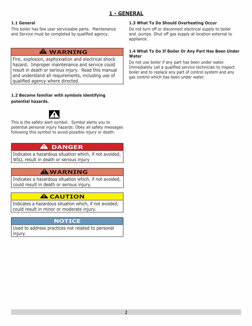
1.1 GeneralThis boiler has few user serviceable parts. Maintenance and Service must be completed by qualified agency.
NOTICEUsed to address practices not related to personal injury.
CAUTIONIndicates a hazardous situation which, if not avoided, could result in minor or moderate injury.
!
WARNINGIndicates a hazardous situation which, if not avoided, could result in death or serious injury.
!
DANGERIndicates a hazardous situation which, if not avoided, WILL result in death or serious injury
!
This is the safety alert symbol. Symbol alerts you to potential personal injury hazards. Obey all safety messages following this symbol to avoid possible injury or death.
1.2 Become familiar with symbols identifyingpotential hazards.
1.3 What To Do Should Overheating OccurDo not turn off or disconnect electrical supply to boiler and pumps. Shut off gas supply at location external to appliance.
1.4 What To Do If Boiler Or Any Part Has Been Under WaterDo not use boiler if any part has been under water. Immediately call a qualified service technician to inspect boiler and to replace any part of control system and any gas control which has been under water.
1 - GENERAL
WARNINGFire, explosion, asphyxiation and electrical shock hazard. Improper maintenance and service could result in death or serious injury. Read this manual and understand all requirements, including use of qualified agency where directed.
!

3
FOR YOUR SAFETY READ BEFORE OPERATING WARNINGIf you do not follow these instructions exactly, a fire or explosion may result causing property damage, personal injury or loss of life.• This appliance is equipped with an ignition device
which automatically lights burner. Do NOT try to light this burner by hand.
• Before operating smell all around appliance area for gas. Be sure to smell next to floor because some gas is heavier than air and will settle to the floor.
• Use only your hand to turn the gas shutoff valve. Never use tools. If valve will not turn by hand, do not try to repair it, call a qualified service technician. Force or attempted repair may result in fire or explosion.
• Do not use this appliance if any part has been under water. Immediately call a qualified service technician to inspect appliance and to replace any part of control system and any gas control which has been under water.
!
2.1 Operating InstructionsStop! Read Safety information above.
• Set thermostat to lowest setting.
• Turn "OFF" all electrical power to appliance.
• This appliance is equipped with an ignition device which automatically lights the burner. Do not try to light burner by hand!
• Remove front jacket panel.
• Turn gas shutoff valve to closed position. Handle should be perpendicular to gas pipe. See Figures 2-1 and 2-2.
• Wait 5 minutes for any gas to clear. Smell for gas, including near floor. If you smell gas, STOP! Follow instructions on this page: “What To Do If You Smell Gas.” If you do not smell gas, go to next step.
• Turn gas shutoff valve to the open position. Handle should be parallel to gas pipe.
• Replace front jacket panel.
• Turn "ON" electrical power to appliance.
• Set thermostat to desired setting.
• If the appliance will not operate, follow instructions TO TURN OFF GAS TO APPLIANCE and call your service technician or gas supplier.
CAUTIONWHAT TO DO IF YOU SMELL GAS
• Do not try to light any appliance.
• Do not touch any electrical switch; do not use any phone in your building.
• Immediately call your gas supplier from a neighbor’s phone. Follow the gas supplier’s instructions.
• If you cannot reach your gas supplier, call the fire department.
!
2.2 To Turn Off Gas To Appliance• Set thermostat to lowest setting.• Turn "OFF" all electric power to appliance if service is
to be performed.• Remove front jacket panel.• Turn gas shutoff valve handle to closed position.
Handle should be perpendicular to gas pipe. See Fig-ures 2-1 and 2-2.
• Replace front jacket panel.
2 - OPERATING INSTRUCTIONS
2-1 Gas Shutoff Valve Outside Boiler Jacket (view from top rear of boiler)
Supplied Manual Main Gas
Shutoff Valve (shown in open
position)
PIPE
PIPEGAS SHUTOFF VALVE
GAS SHUTOFF VALVE
2-1 Gas Shutoff Valve - Closed Position

4
Operation with LCD character display module
4.3 Status IndicationThe following status screens can be displayed:
S E R V I C E R e m i n d e r
4.1 IntroductionBoiler is equipped with programmable electronic control and user interface module.
4.2 OperationKey Description
- Manual Lockout Reset
- Enter/Exit user menu- Go to previous screen- Select a menu item - Confirm new parameter value- Scroll up to next menu item- Increase value
- Scroll down to next menu item- Decrease value
Boiler Status Indicator F = Flame Detected P = Central Heating/System Pump On B = Combustion Air Blower On S = Safety Relay Check G = Gas Valve Open D = DHW Pump On
Service Reminder IndicatorBoiler in Standby ModeBoiler Supply Water Temperature Indicator
Boiler Running in Central Heat modeCombustion Air Blower
Speed Indicator
Boiler Running in DHW mode
Lockout Alarm IndicatorError code and short text de-scription displayed.Press Reset key for manual reset.
Blocking ErrorError code and short text description displayed. Boiler automatically returns to Standby Mode when condition eliminated.
4 - CONTROL MODULE

5
Operational State User Interface Display Explanation
Boiler operates in standby mode until demand for Central Heat (CH) or Domestic Hot Water (DHW) detected.
Call for heat.
CH/System or DHW pump turned ON based on type of heating demand. Heat Exchanger Pump also turned ON.
(CH demand illustrated)
Combustion Air Blower energized.
Combustion Air Blower speed modulates to prepurge setting for 15 seconds.
Igniter energized to start sparking sequence.
Gas Valve energized to deliver air/fuel to burner.
Igniter de-energized.
Boiler runs provided all operational and safety devices within limits.
Control Module adjusts firing rate to match heating demand.Call for heat ends. Post purge cycle for 30 seconds.
Combustion Air Blower modulates to post purge setting.
CH/System Pump, DHW pump, and Heat Exchanger Pump operate.
Boiler returns to Standby Mode.
4.4 Sequence of Operation
4 - CONTROL MODULE
Ready forOperation
Thermostat StartsCall for Heat
Pre-Purge
Trial for Ignition
Thermostat EndsCall for Heat
Post-Purge
Normal Operation
Ready forOperation
6
4 - CONTROL MODULE
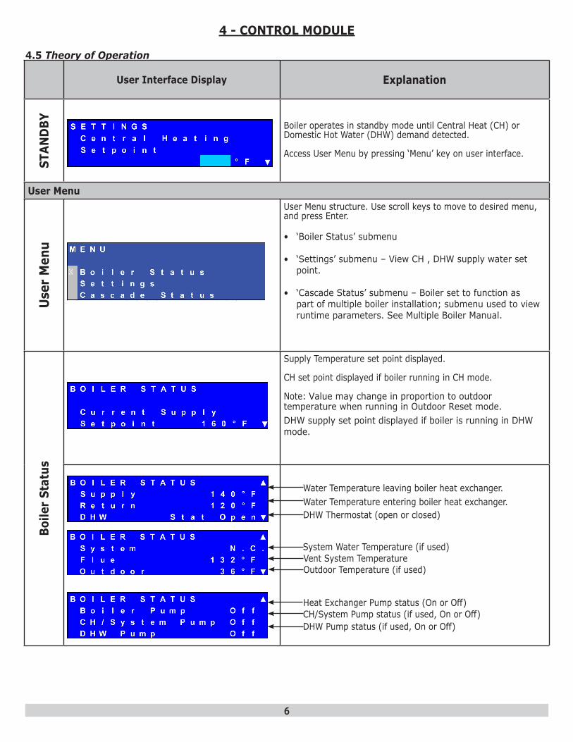
4.5 Theory of Operation
User Interface Display Explanation
STAN
DBY Boiler operates in standby mode until Central Heat (CH) or
Domestic Hot Water (DHW) demand detected.
Access User Menu by pressing ‘Menu’ key on user interface.
User Menu
Use
r M
enu
User Menu structure. Use scroll keys to move to desired menu, and press Enter.
• ‘Boiler Status’ submenu
• ‘Settings’ submenu – View CH , DHW supply water set point.
• ‘Cascade Status’ submenu – Boiler set to function as part of multiple boiler installation; submenu used to view runtime parameters. See Multiple Boiler Manual.
Boile
r St
atus
Supply Temperature set point displayed.
CH set point displayed if boiler running in CH mode.
Note: Value may change in proportion to outdoor temperature when running in Outdoor Reset mode.DHW supply set point displayed if boiler is running in DHW mode.
Water Temperature leaving boiler heat exchanger.Water Temperature entering boiler heat exchanger.
Heat Exchanger Pump status (On or Off)CH/System Pump status (if used, On or Off)DHW Pump status (if used, On or Off)
DHW Thermostat (open or closed)
System Water Temperature (if used)Vent System TemperatureOutdoor Temperature (if used)

7
User Interface Display Explanation
Sett
ings
Setting Range: 104° F to 195° F (40° C to 91° C)Default Value: 140° F (60° C)
Adjust CH set point to hydronic system design while in Operating in CH Mode = 0 (CH with Thermostat) or 3 (Permanent Demand).
In CH Mode = 1 (CH with Thermostat and Outdoor Reset) or 2 (CH with Full Outdoor Reset). Display will change to ‘OD Reset Setpoint’ and cannot be changed. Control Module calculates set point based on outdoor temperature.
Setting Range: 104° F to 195° F (40° C to 91° C)Default Value: 180° F (82° C)
DHW set point determines supply water temperature set point when operating in DHW mode.
Contact qualified agency to make changes.
Select temperature unit of measure.
Fahrenheit °F or Celsius °C.
4 - CONTROL MODULE

8
5 - TROUBLE SHOOTING
Is P
ower
ligh
t ON
?
YES
NO
Is R
eset
Lig
ht O
N?
YES
NO
Con
tact
Qua
lifie
d A
genc
y to
Ser
vice
B
oile
rIs
mai
n ci
rcui
t bre
aker
in O
N
posi
tion?
YES
NO
Con
tact
Qua
lifie
d A
genc
y to
Ser
vice
B
oile
rR
eset
circ
uit b
reak
er
Is P
ower
Sw
itch
ON
?(C
heck
all
boile
r pow
er s
witc
hes)
YES
NO Pl
ace
all b
oile
r Pow
er
Switc
hes
in O
N
posi
tion
Is H
eat L
ight
ON
?
YES
NO
Che
ck T
herm
osta
t Se
tting
Boi
ler i
s in
Sta
nd-b
y M
ode

9
6 - MAINTENANCEPerform general housekeeping and maintenance as specified below.
6.1 Continuous• Keep boiler area free from combustible materials,
gasoline and other flammable vapors and liquids.
• Keep combustion air and vent terminations (outside building) free from trash, vegetation and other items capable of blocking flow.
6.2 Monthly• Inspect combustion air, vent, and condensate drain
piping for deterioration, leaks or sagging. Contact qualified agency, as necessary.
• Inspect condensate drain trap. See Figure 6-1.
• Follow instructions TO TURN OFF GAS TO APPLIANCE. See section 2.
• Inspect condensate drain trap for sediment or blockage. Contact qualified agency if cleaning required.
• Inspect system piping for leaks. Contact qualified agency, as necessary.
• Check air vent(s) for leakage.
• Follow OPERATING INSTRUCTIONS to return to normal operation.
6.3 Check According to Manufacturer's Instructions• Safety Relief Valve - Refer to manufacturer's
instructions. See Figure 6-2.
WARNINGBurn and scald hazard. Verify Safety Relief Valve dis-charge piping run to safe discharge location before con-ducting maintenance procedure. Contact qualified agency to correct improper piping.
!
6.4 Annually or Beginning Each Heating Season• Contact qualified agency to perform maintenance and
cleaning per Installation, Operation and Maintenance manual. Inspection will include examining all flue product carrying areas, vent system, burner and heat exchanger. Will also include filling boiler with water if drained as part of End of Heating Season procedure.
FIGURE 6-1 Condensate Drain
FIGURE 6-2 Safety Relief Valve Discharge Piping
WARNINGAsphyxiation hazard. Contact qualified agency if conden-sate trap is not filled with water.
!
Check Local Codes For Maximum
Distance To Floor
Safety Relief Valve
Secure Hose onto Hose Barb with Spring Tension
Clip

10
6 - MAINTENANCE6.5 End Of Heating Season, If Boiler Not Used For Domestic Hot Water.
• Follow instructions to TURN OFF GAS TO APPLIANCE. See section 2.
• Contact qualified agency to drain heating system (if system does not use antifreeze) and condensate trap if heating system is exposed to freezing temperatures while out of service.

11
Name:
Address:
Phone: Email:
Installer Information