Embed Size (px)
Citation preview
www.greyline.com
USER'S GUIDE Installation & Operation
Instructions
Area-Velocity Flow Meter
Model AVFM 5.0
Manual Series A.2.2

Note: This page has been left blank intentionally.
Page 3
AVFM 5.0 Area-Velocity Flow Meter
INDEX
CONNECTIONS ................................................................................................ 4
FUNCTION TEST .............................................................................................. 4
KEYPAD SYSTEM ............................................................................................ 6
CALIBRATION MENU ..................................................................................... 7
ICONS ................................................................................................................. 8
MESSAGE ICON ............................................................................................... 9
STATUS ............................................................................................................. 9
PASSWORD ..................................................................................................... 10
UNITS/MODE .................................................................................................. 11
CALIBRATION................................................................................................ 12
RELAY PARAMETERS .................................................................................. 16
SPECIAL FUNCTIONS ................................................................................... 17
INSTALLATION - SENSOR LOCATION ...................................................... 19
ENCLOSURE INSTALLATION ..................................................................... 23
FIELD TROUBLESHOOTING ........................................................................ 25
APPLICATIONS HOTLINE ............................................................................ 27
PRODUCT RETURN PROCEDURE ............................................................... 28
AREA-VELOCITY FLOW DATA SHEET ..................................................... 29
APPENDIX A – OPTIONS ............................................................................... 31
DATA LOGGING (OPTIONAL) ......................................................................... 39
SPECIFICATIONS ........................................................................................... 41
IMPORTANT NOTE: This instrument is manufactured and calibrated to meet product specifications. Please read this manual carefully before installation and operation. Any unauthorized repairs or modifications may result in a suspension of the warranty.
Available in Adobe Acrobat pdf format
Page 4
AVFM 5.0 Area-Velocity Flow Meter
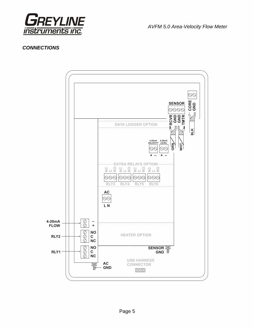
CONNECTIONS
POWER INPUT: 100 to 240 VAC 50/60Hz. No adjustments are necessary for voltages within this range. Connect L (Live) N (Neutral) and AC Ground.
Optional DC: 9-32 VDC. Connect to + and - terminals.
Optional Thermostat and Heater modules are available rated for 115 VAC or 230 VAC.
IMPORTANT NOTE: To comply with CSA/UL electrical safety standards, AC power input and relay connection wires must have conduit entry to the instrument enclosure. Installation requires a switch, overcurrent fuse or circuit breaker in the building (in close proximity to the equipment) that is marked as the disconnect switch.
Risk of electric shock. Loosen cover screw to access connections. Only qualified personnel should access connections.
Note: Use of instrumentation over 40°C ambient requires special field wiring.
Note: User replaceable fuse is 2 Amp 250V (T2AL250V).
FUNCTION TEST:
Connect the sensor to the sensor terminals as shown on next page, then apply power. Allow 30 seconds for the AVFM 5.0 to initialize.
A. Place QZ02L sensor (flat to the bottom) in a bucket of water about 6” deep and select Level mode (from UNITS/MODE menu) to see a level reading.
B. Select Velocity mode and stir the water to see a velocity reading.
!
Page 5
AVFM 5.0 Area-Velocity Flow Meter
CONNECTIONS
HEATER OPTION
AC
L N
NOCNC
NOCNC
–+
4-20mAFLOW
RLY2
RLY1
ACGND
SENSORGND
NC
C NO
NC
C NO
NC
C NO
NC
C NO
RLY3 RLY4 RLY5 RLY6
EXTRA RELAYS OPTION
4-20mAVELOCITY
4-20mALEVEL
CO
RE
GN
D
GR
N
WH
T
BL
K
DATA LOGGER OPTION
USB HARNESSCONNECTOR
+ +– –
RC
VR
GN
DG
ND
TM
TR
SENSOR

Page 6
AVFM 5.0 Area-Velocity Flow Meter
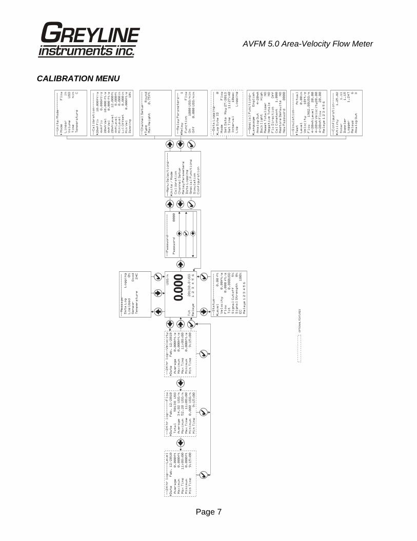
KEYPAD SYSTEM
The AVFM 5.0 uses a menu system. Arrows show the four directions to leave a menu box. Pressing a corresponding keypad arrow will move to the next item in the direction shown. Move the cursor (underline) under numerals and increase or decrease numerals with the and keys.
To store calibration values permanently (even through power interruptions), press .
Page 7
AVFM 5.0 Area-Velocity Flow Meter
CALIBRATION MENU
--
Pa
ss
wo
rd
--
--
--
--
--
Pa
ss
wo
rd
00
00
--
Un
it
s/
Mo
de
--
--
--
--
Mo
de
Fl
ow
�
Li
ne
ar
in
Vo
lu
me
US
G
Ti
me
mi
n
Te
mp
er
at
ur
eC
US
G/
m
To
t
2
01
30
.8
US
G
Re
la
ys
1
2
3
4
5
6
0.000
--
Me
ss
ag
e-
--
--
--
--
--
Da
ta
Lo
gL
og
gi
ng
dL
og
Us
e0
%
Se
ns
or
Go
od
Te
mp
er
at
ur
e2
4C
--
St
at
us
--
--
--
--
--
--
�L
ev
el
0.
00
ft
Ve
lo
ci
ty
0.
00
ft
/s
Fl
ow
0.
00
0 f
t/
s
To
t0
.0
00
US
G
Si
gn
al
Cu
to
ff
5%
Si
gn
al
St
re
ng
th
0%
EC
10
0%
Re
la
ys
1 2
3 4
5 6
--
Ca
li
br
at
io
n-
--
--
--
�2
0m
A F
lo
10
.0
00
ft
/s
³
4m
A F
lo
0.
00
0f
t/
s³
20
mA
Ve
l1
0.
00
0 f
t/
s
4m
A V
el
0.
00
0 f
t/
s
20
mA
Le
ve
l1
2.
00
0f
t
4m
A L
ev
el
0.
00
0f
t
Mi
n L
ev
el
0.
00
0i
n
Lv
l O
ff
se
t0
.0
00
in
Mi
n V
el
0.
00
0f
t/
s
Da
mp
in
g1
0%
--
Re
la
y P
ar
am
et
er
s-
-
Re
la
y1
�
Fu
nc
ti
on
Fl
ow
/m
in
On
10
00
US
G
/m
in
Of
f0
.0
00
US
G
--
Sp
ec
ia
l F
un
ct
io
ns
-
La
ng
ua
ge
En
gl
is
h�
An
al
og
Ou
t4
-2
0m
A
Ba
ck
li
gh
tH
ig
h
Re
se
t T
ot
al
iz
er
NO
Ne
ga
ti
ve
To
ta
ls
NO
Fl
o D
ir
ec
ti
on
Of
f
Ca
l C
on
st
an
t1
.0
00
Re
st
or
e D
ef
au
lt
sN
O
Ne
w P
as
sw
or
d0
00
0
--
Da
ta
Lo
gg
in
g-
--
--
--
Lo
g S
it
e I
D0
�
Mo
de
Fl
ow
Se
t D
at
eM
ay
27
/2
01
3
Se
t T
im
e1
1:
27
:4
0
In
te
rv
al
10
se
c
Lo
gL
og
gi
ng
--
Co
nf
ig
ur
at
io
n-
--
--
�U
ti
li
ty
1.
25
.0
2
So
na
r1
.1
1
Do
pp
le
r1
.1
5
24
Lo
gg
er
1.
T 6R
el
ay
s
An
al
og
Ou
t3
--
--
--
-C
ha
nn
el
Se
tu
p-
�T
yp
eR
ou
nd
Ma
x H
ei
gh
t0
.7
5f
t
--
Me
nu
Se
le
ct
io
ns
--
--
Un
it
s /
Mo
de
�
Ca
li
br
at
io
n
Ch
an
ne
l S
et
up
Re
la
y P
ar
am
et
er
s
Da
ta
Lo
gg
in
g
Sp
ec
ia
l F
un
ct
io
ns
Si
mu
la
ti
on
Co
nf
ig
ur
at
io
n
OP
TIO
NA
LF
EA
TU
RE
S
--
24
hr
lo
g-
--
--
-F
lo
w
Da
te
Fe
b.
12
/2
0�
10
50
13
8
US
GT
ot
al
34
.8
2
US
G/
mA
ve
ra
ge
52
.2
0
US
G/
mM
ax
im
um
11
:0
8:
00
Ma
x T
im
e
0.
00
0
US
G/
mM
in
im
um
9:
15
:0
0M
in
Ti
me
--
24
hr
lo
g-
--
--
Le
ve
l
Da
te
Fe
b.
12
/2
0�
10
0.
00
0f
tA
ve
ra
ge
0.
00
0f
tM
ax
im
um
11
:0
8:
00
Ma
x T
im
e
0.
00
0f
tM
in
im
um
9:
15
:0
0M
in
Ti
me
--
24
hr
lo
g-
-V
el
oc
it
y
Da
te
Fe
b.
12
/2
0�
10
0.
00
0f
t/
sA
ve
ra
ge
0.
00
0f
t/
sM
ax
im
um
11
:0
8:
00
Ma
x T
im
e
0.
00
0f
t/
sM
in
im
um
9:
15
:0
0M
in
Ti
me
--
Si
mu
la
ti
on
--
--
--
--
�T
es
tA
ct
ua
l
Le
ve
l0
.0
0i
n
Ve
lo
ci
ty
10
ft
/s
Fl
ow
19
82
.8
8U
SG
/m
4-
20
mA
Le
ve
l2
0.
00
4-
20
mA
Ve
lo
ci
ty
20
.0
0
4-
20
mA
Fl
ow
20
.0
0
Re
la
ys
1 2
3 4
5 6
Page 8
AVFM 5.0 Area-Velocity Flow Meter
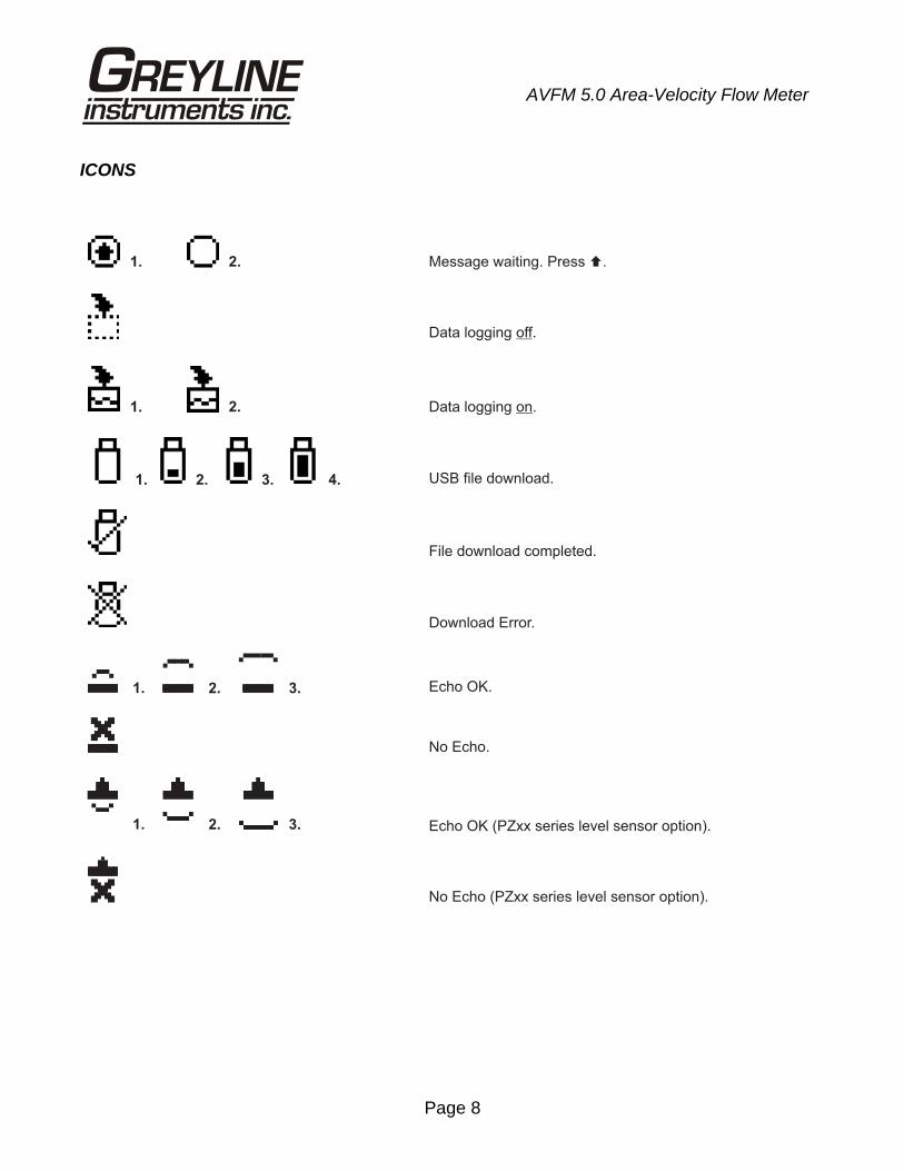
ICONS
1. 2. Message waiting. Press .�
Data logging .off
1. 2. Data logging .on
1. 2. 3. 4. USB file download.
File download completed.
Download Error.
Echo OK (PZxx series level sensor option).
No Echo.
Echo OK.3.
3.
2.
2.
1.
1.
No Echo (PZxx series level sensor option).
Page 9
AVFM 5.0 Area-Velocity Flow Meter
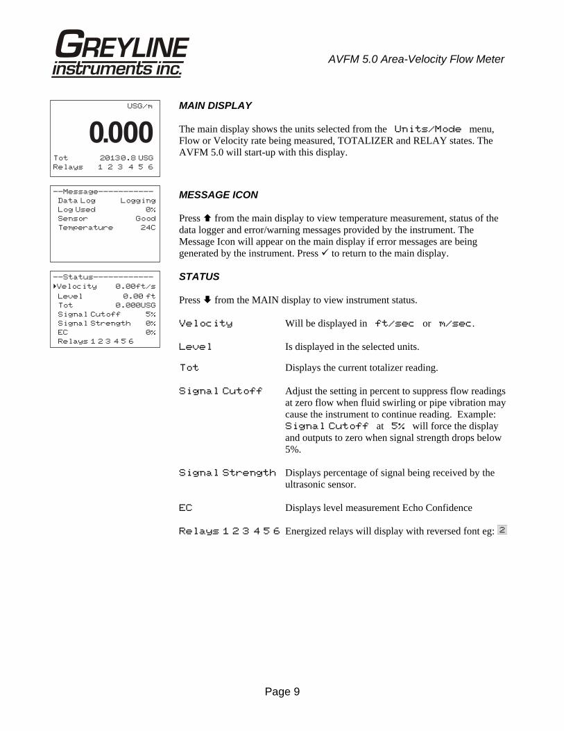
MAIN DISPLAY The main display shows the units selected from the Units/Mode menu, Flow or Velocity rate being measured, TOTALIZER and RELAY states. The AVFM 5.0 will start-up with this display.
MESSAGE ICON Press from the main display to view temperature measurement, status of the data logger and error/warning messages provided by the instrument. The Message Icon will appear on the main display if error messages are being generated by the instrument. Press to return to the main display.
STATUS Press from the MAIN display to view instrument status. Velocity Will be displayed in ft/sec or m/sec. Level Is displayed in the selected units. Tot Displays the current totalizer reading. Signal Cutoff Adjust the setting in percent to suppress flow readings
at zero flow when fluid swirling or pipe vibration may cause the instrument to continue reading. Example: Signal Cutoff at 5% will force the display and outputs to zero when signal strength drops below 5%.
Signal Strength Displays percentage of signal being received by the
ultrasonic sensor. EC Displays level measurement Echo Confidence Relays 1 2 3 4 5 6 Energized relays will display with reversed font eg:
USG/m
Tot 20130.8 USG
Relays 1 2 3 4 5 6
0.000
--Message-----------
Data Log Logging
dLog Use 0%
Sensor Good
Temperature 24C
--Status------------
Velocity 0.00ft/s
Level 0.00 ft
Tot 0.000USG
Signal Cutoff 5%
Signal Strength 0%
EC 0%
Relays 1 2 3 4 5 6
�
Page 10
AVFM 5.0 Area-Velocity Flow Meter
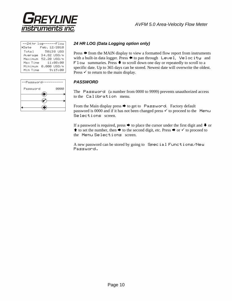
24 HR LOG (Data Logging option only) Press from the MAIN display to view a formatted flow report from instruments with a built-in data logger. Press to pan through Level, Velocity and Flow summaries. Press to scroll down one day or repeatedly to scroll to a specific date. Up to 365 days can be stored. Newest date will overwrite the oldest. Press to return to the main display.
PASSWORD The Password (a number from 0000 to 9999) prevents unauthorized access to the Calibration menu. From the Main display press to get to Password. Factory default password is 0000 and if it has not been changed press to proceed to the Menu
Selections screen. If a password is required, press to place the cursor under the first digit and or to set the number, then to the second digit, etc. Press or to proceed to the Menu Selections screen. A new password can be stored by going to Special Functions/New Password.
--24 hr log------Flow
Date Feb. 12/2010
Total 50138 USG
Average 34.82 USG/m
Maximum 52.20 USG/m
Max Time 11:08:00
Minimum 0.000 USG/m
Min Time 9:15:00
�
--Password----------
Password 0000
Page 11
AVFM 5.0 Area-Velocity Flow Meter
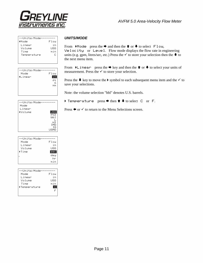
UNITS/MODE From Mode press the and then the or to select Flow, Velocity or Level. Flow mode displays the flow rate in engineering units (e.g. gpm, litres/sec, etc.) Press the to store your selection then the to the next menu item. From Linear press the key and then the or to select your units of measurement. Press the to store your selection. Press the key to move the symbol to each subsequent menu item and the to save your selections. Note: the volume selection "bbl" denotes U.S. barrels. Temperature press then to select C or F. Press or to return to the Menu Selections screen.
--Units/Mode--------
Mode Flow
Linear in
Volume USG
Time min
Temperature C
�
--Units/Mode--------
Mode Flow
Linear� in
ftm
mm
--Units/Mode--------
Mode
Linear
�Volume USG
ft3bbl
Lm3
IMGIG
USMG
--Units/Mode--------
Mode Flow
Linear in
Volume USG
Time� sec
day
hr
min
--Units/Mode--------
Mode Flow
Linear in
Volume USG
Time min
Temperature� C
F
Page 12
AVFM 5.0 Area-Velocity Flow Meter
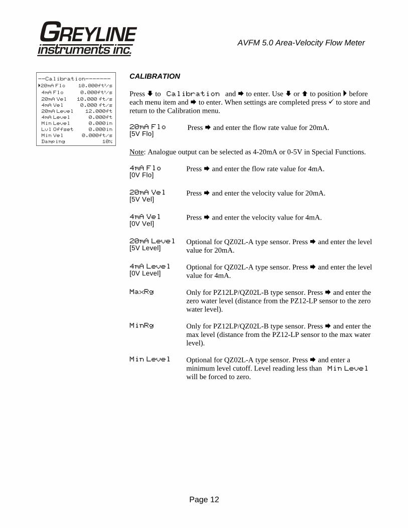
CALIBRATION Press to Calibration and to enter. Use or to position before each menu item and to enter. When settings are completed press to store and return to the Calibration menu. 20mA Flo[5V Flo]
Press and enter the flow rate value for 20mA.
Note: Analogue output can be selected as 4-20mA or 0-5V in Special Functions. 4mA Flo [0V Flo]
Press and enter the flow rate value for 4mA.
20mA Vel[5V Vel]
Press and enter the velocity value for 20mA.
4mA Vel [0V Vel]
Press and enter the velocity value for 4mA.
20mA Level[5V Level]
Optional for QZ02L-A type sensor. Press and enter the level value for 20mA.
4mA Level[0V Level]
Optional for QZ02L-A type sensor. Press and enter the level value for 4mA.
MaxRg Only for PZ12LP/QZ02L-B type sensor. Press and enter the zero water level (distance from the PZ12-LP sensor to the zero water level).
MinRg Only for PZ12LP/QZ02L-B type sensor. Press and enter the max level (distance from the PZ12-LP sensor to the max water level).
Min Level Optional for QZ02L-A type sensor. Press and enter a minimum level cutoff. Level reading less than Min Level will be forced to zero.
--Calibration-------
�20mA Flo 10.000ft /s³
4mA Flo 0.000ft /s³
20mA Vel 10.000 ft/s
4mA Vel 0.000 ft/s
20mA Level 12.000ft
4mA Level 0.000ft
Min Level 0.000in
Lvl Offset 0.000in
Min Vel 0.000ft/s
Damping 10%
Page 13
AVFM 5.0 Area-Velocity Flow Meter
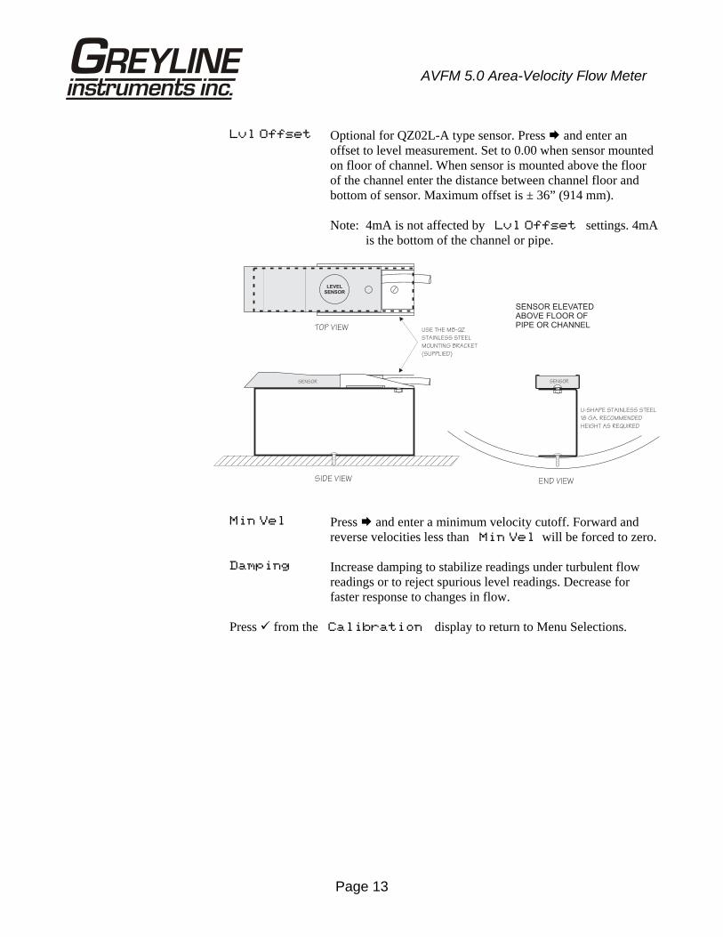
Lvl Offset Optional for QZ02L-A type sensor. Press and enter an offset to level measurement. Set to 0.00 when sensor mounted on floor of channel. When sensor is mounted above the floor of the channel enter the distance between channel floor and bottom of sensor. Maximum offset is ± 36” (914 mm).
Note: 4mA is not affected by Lvl Offset settings. 4mA is the bottom of the channel or pipe.
Min Vel Press and enter a minimum velocity cutoff. Forward and
reverse velocities less than Min Vel will be forced to zero.
Damping Increase damping to stabilize readings under turbulent flow readings or to reject spurious level readings. Decrease for faster response to changes in flow.
Press from the Calibration display to return to Menu Selections.
SENSOR
END VIEWSIDE VIEW
TOP VIEW
SENSOR
U-SHAPE STAINLESS STEEL
18 GA. RECOMMENDED
HEIGHT AS REQUIRED
USE THE MB-QZ
STAINLESS STEEL
MOUNTING BRACKET
(SUPPLIED)
SENSOR ELEVATEDABOVE FLOOR OFPIPE OR CHANNEL
LEVEL
SENSOR
Page 14
AVFM 5.0 Area-Velocity Flow Meter
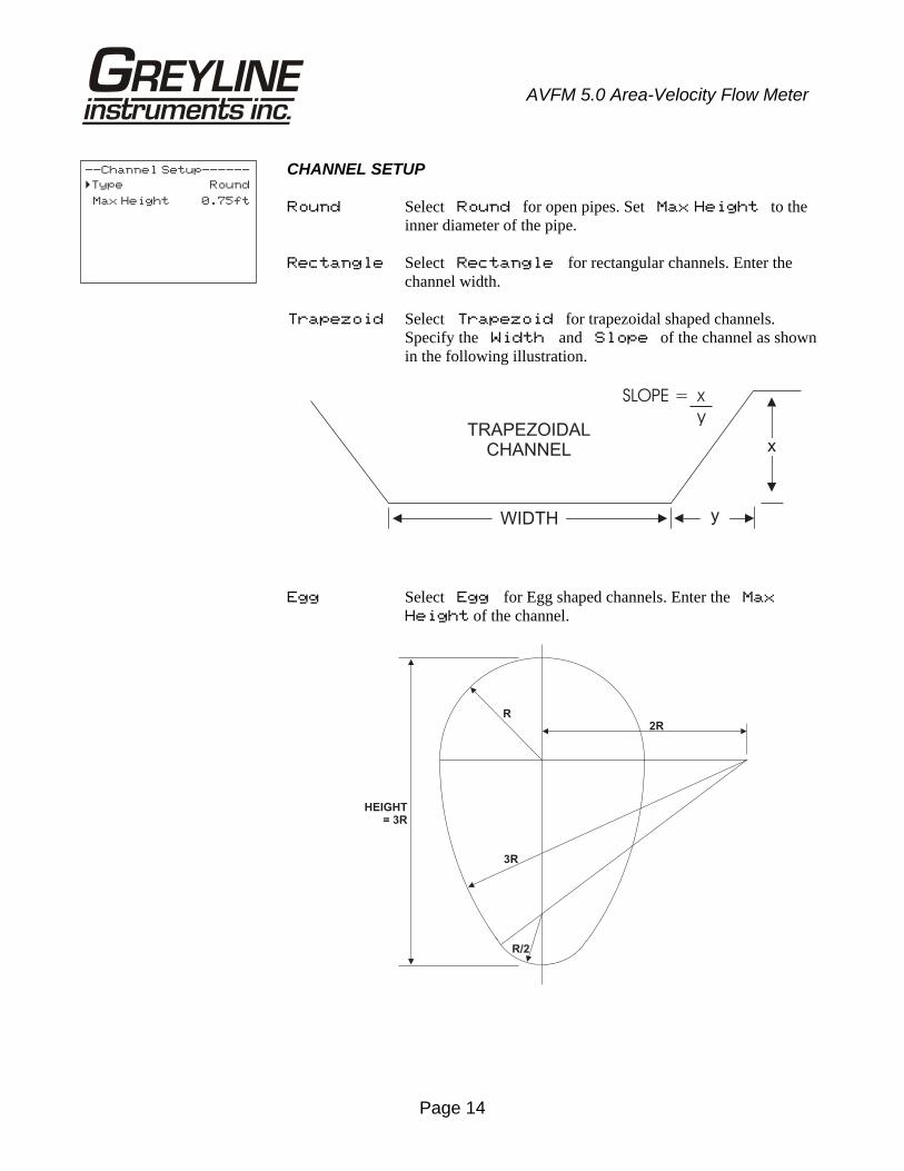
CHANNEL SETUP Round Select Round for open pipes. Set Max Height to the
inner diameter of the pipe. Rectangle Select Rectangle for rectangular channels. Enter the
channel width. Trapezoid Select Trapezoid for trapezoidal shaped channels.
Specify the Width and Slope of the channel as shown in the following illustration.
Egg Select Egg for Egg shaped channels. Enter the Max
Height of the channel.
--Channel Setup------
Type Round
Max Height 0.75ft
�
R
3R
R/2
2R
HEIGHT
= 3R
TRAPEZOIDALCHANNEL
yWIDTH
x
SLOPE = x
y
Page 15
AVFM 5.0 Area-Velocity Flow Meter
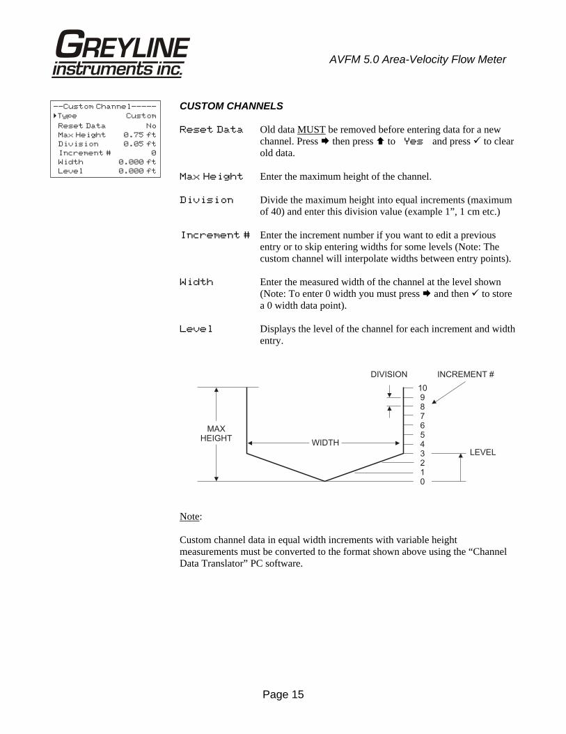
CUSTOM CHANNELS Reset Data Old data MUST be removed before entering data for a new
channel. Press then press to Yes and press to clear old data.
Max Height Enter the maximum height of the channel. Division Divide the maximum height into equal increments (maximum
of 40) and enter this division value (example 1”, 1 cm etc.) Increment # Enter the increment number if you want to edit a previous
entry or to skip entering widths for some levels (Note: The custom channel will interpolate widths between entry points).
Width Enter the measured width of the channel at the level shown
(Note: To enter 0 width you must press and then to store a 0 width data point).
Level Displays the level of the channel for each increment and width
entry.
Note: Custom channel data in equal width increments with variable height measurements must be converted to the format shown above using the “Channel Data Translator” PC software.
--Custom Channel-----
Type Custom
Reset Data No
Max Height 0.75 ft
Division 0.05 ft
Increment # 0
Width 0.000 ft
Level 0.000 ft
�
MAXHEIGHT
109876543210
WIDTH
INCREMENT #DIVISION
LEVEL
Page 16
AVFM 5.0 Area-Velocity Flow Meter
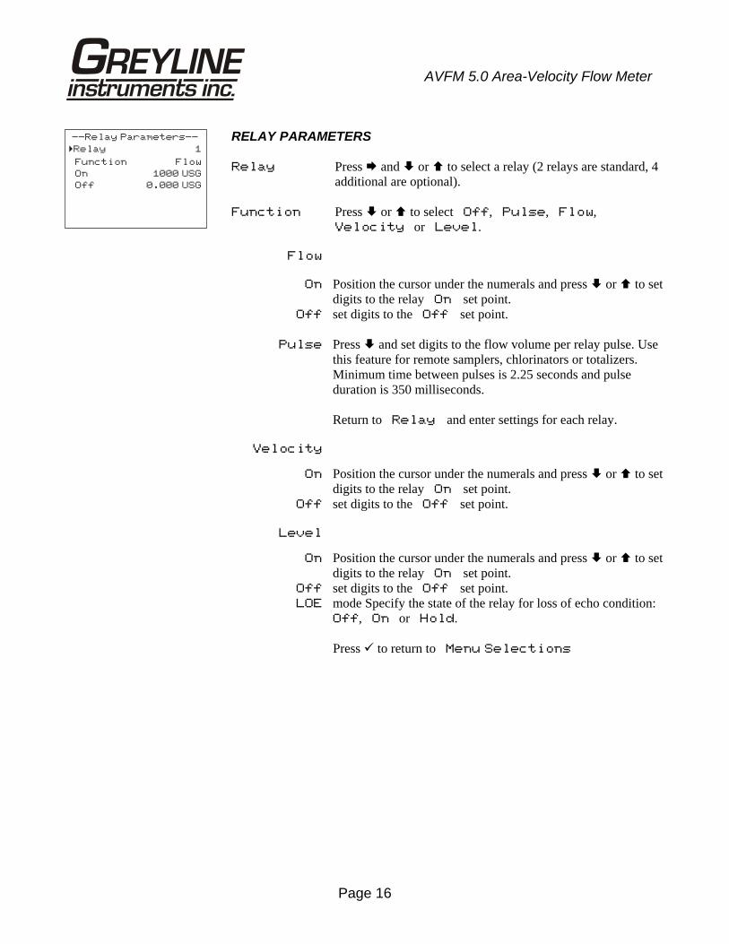
RELAY PARAMETERS Relay Press and or to select a relay (2 relays are standard, 4
additional are optional). Function Press or to select Off, Pulse, Flow,
Velocity or Level. Flow On Position the cursor under the numerals and press or to set
digits to the relay On set point. Off set digits to the Off set point. Pulse Press and set digits to the flow volume per relay pulse. Use
this feature for remote samplers, chlorinators or totalizers. Minimum time between pulses is 2.25 seconds and pulse duration is 350 milliseconds.
Return to Relay and enter settings for each relay. Velocity On Position the cursor under the numerals and press or to set
digits to the relay On set point. Off set digits to the Off set point. Level On Position the cursor under the numerals and press or to set
digits to the relay On set point. Off set digits to the Off set point. LOE mode Specify the state of the relay for loss of echo condition:
Off, On or Hold.
Press to return to Menu Selections
--Relay Parameters--
Relay 1
Function Flow
On 1000 USG
Off 0.000 USG
�
Page 17
AVFM 5.0 Area-Velocity Flow Meter
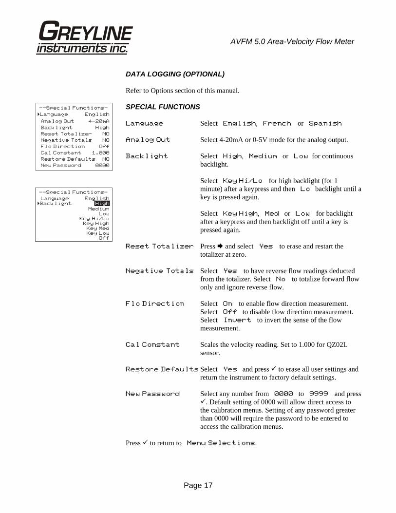
DATA LOGGING (OPTIONAL) Refer to Options section of this manual. SPECIAL FUNCTIONS Language Select English, French or Spanish Analog Out Select 4-20mA or 0-5V mode for the analog output. Backlight Select High, Medium or Low for continuous
backlight. Select Key Hi/Lo for high backlight (for 1 minute) after a keypress and then Lo backlight until a key is pressed again. Select Key High, Med or Low for backlight after a keypress and then backlight off until a key is pressed again.
Reset Totalizer Press and select Yes to erase and restart the
totalizer at zero. Negative Totals Select Yes to have reverse flow readings deducted
from the totalizer. Select No to totalize forward flow only and ignore reverse flow.
Flo Direction Select On to enable flow direction measurement.
Select Off to disable flow direction measurement. Select Invert to invert the sense of the flow measurement.
Cal Constant Scales the velocity reading. Set to 1.000 for QZ02L
sensor. Restore Defaults Select Yes and press to erase all user settings and
return the instrument to factory default settings. New Password Select any number from 0000 to 9999 and press
. Default setting of 0000 will allow direct access to the calibration menus. Setting of any password greater than 0000 will require the password to be entered to access the calibration menus.
Press to return to Menu Selections.
--Special Functions-
Language English
Analog Out 4-20mA
Backlight High
Reset Totalizer NO
Negative Totals NO
Flo Direction Off
Cal Constant 1.000
Restore Defaults NO
New Password 0000
�
--Special Functions-
Language English�Backlight High
MediumLow
Key Hi/LoKey High
Key MedKey Low
Off
Page 18
AVFM 5.0 Area-Velocity Flow Meter
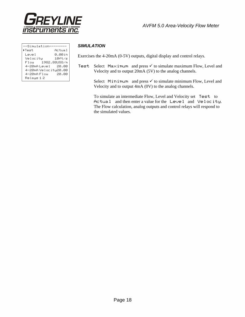
SIMULATION Exercises the 4-20mA (0-5V) outputs, digital display and control relays. Test Select Maximum and press to simulate maximum Flow, Level and
Velocity and to output 20mA (5V) to the analog channels. Select Minimum and press to simulate minimum Flow, Level and
Velocity and to output 4mA (0V) to the analog channels. To simulate an intermediate Flow, Level and Velocity set Test to
Actual and then enter a value for the Level and Velocity. The Flow calculation, analog outputs and control relays will respond to the simulated values.
--Simulation--------
Test Actual
Level 0.00in
Velocity 10ft/s
Flow 1982.88USG/m
4-20mA Level 20.00
4-20mA Velocity20.00
4-20mA Flow 20.00
Relays 1 2
�
Page 19
AVFM 5.0 Area-Velocity Flow Meter
INSTALLATION - SENSOR LOCATION
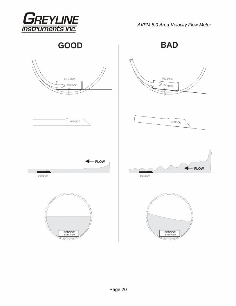
1. Choose a sensor mounting location where silt or deposits are least likely to accumulate.
2. For best results flow should be evenly distributed across the channel and relatively free of turbulence. (The AVFM 5.0 is very effective at averaging level and velocity readings in turbulent conditions, but best accuracy and response time is achieved with evenly distributed flow.)
3. Avoid vertical drops, obstructions or elbows immediately up and downstream from the sensor. Locate the QZ02L sensor at least 10 times maximum Head (level) and 10 times the channel width from these flow disturbances.
4. The QZ02L submerged level-velocity sensor requires a minimum water level of 1 in. (25.4 mm).
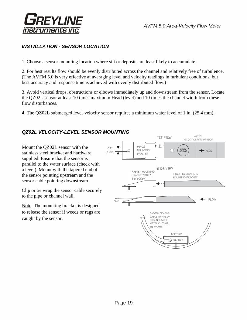
QZ02L VELOCITY-LEVEL SENSOR MOUNTING
Mount the QZ02L sensor with the stainless steel bracket and hardware supplied. Ensure that the sensor is parallel to the water surface (check with a level). Mount with the tapered end of the sensor pointing upstream and the sensor cable pointing downstream.
Clip or tie wrap the sensor cable securely to the pipe or channel wall.
Note: The mounting bracket is designed to release the sensor if weeds or rags are caught by the sensor.
FASTEN SENSOR
CABLE TO PIPE OR
CHANNEL WITH
METAL CLIPS OR
TIE WRAPS
SENSOR
END VIEW
MB-QZ
MOUNTING
BRACKET
0.2"
(5 mm)
TOP VIEW
FLOW
SIDE VIEWFASTEN MOUNTING
BRACKET WITH A
SET SCREW
INSERT SENSOR INTO
MOUNTING BRACKET
QZ02L
VELOCITY/LEVEL SENSOR
FLOWLEVEL
SENSOR
Page 20
AVFM 5.0 Area-Velocity Flow Meter
GOOD BAD
SENSOR
END VIEW
SENSOREND VIEW
SENSOREND VIEW
SENSOR
END VIEW
SENSOR SENSOR
SENSOR
FLOW
SENSOR
FLOW
Page 21
AVFM 5.0 Area-Velocity Flow Meter
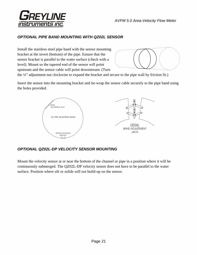
OPTIONAL PIPE BAND MOUNTING WITH QZ02L SENSOR
Install the stainless steel pipe band with the sensor mounting bracket at the invert (bottom) of the pipe. Ensure that the sensor bracket is parallel to the water surface (check with a level). Mount so the tapered end of the sensor will point upstream and the sensor cable will point downstream. (Turn the ¼” adjustment nut clockwise to expand the bracket and secure to the pipe wall by friction fit.)
Insert the sensor into the mounting bracket and tie-wrap the sensor cable securely to the pipe band using the holes provided.
OPTIONAL QZ02L-DP VELOCITY SENSOR MOUNTING
Mount the velocity sensor at or near the bottom of the channel or pipe in a position where it will be continuously submerged. The QZ02L-DP velocity sensor does not have to be parallel to the water surface. Position where silt or solids will not build-up on the sensor.
DETAILBAND ADJUSTMENT
JACK
VSJ PIPE MOUNTING BAND
BAND
ADJUSTMENT JACK
SENSOR MOUNTING
BRACKET
Page 22
AVFM 5.0 Area-Velocity Flow Meter
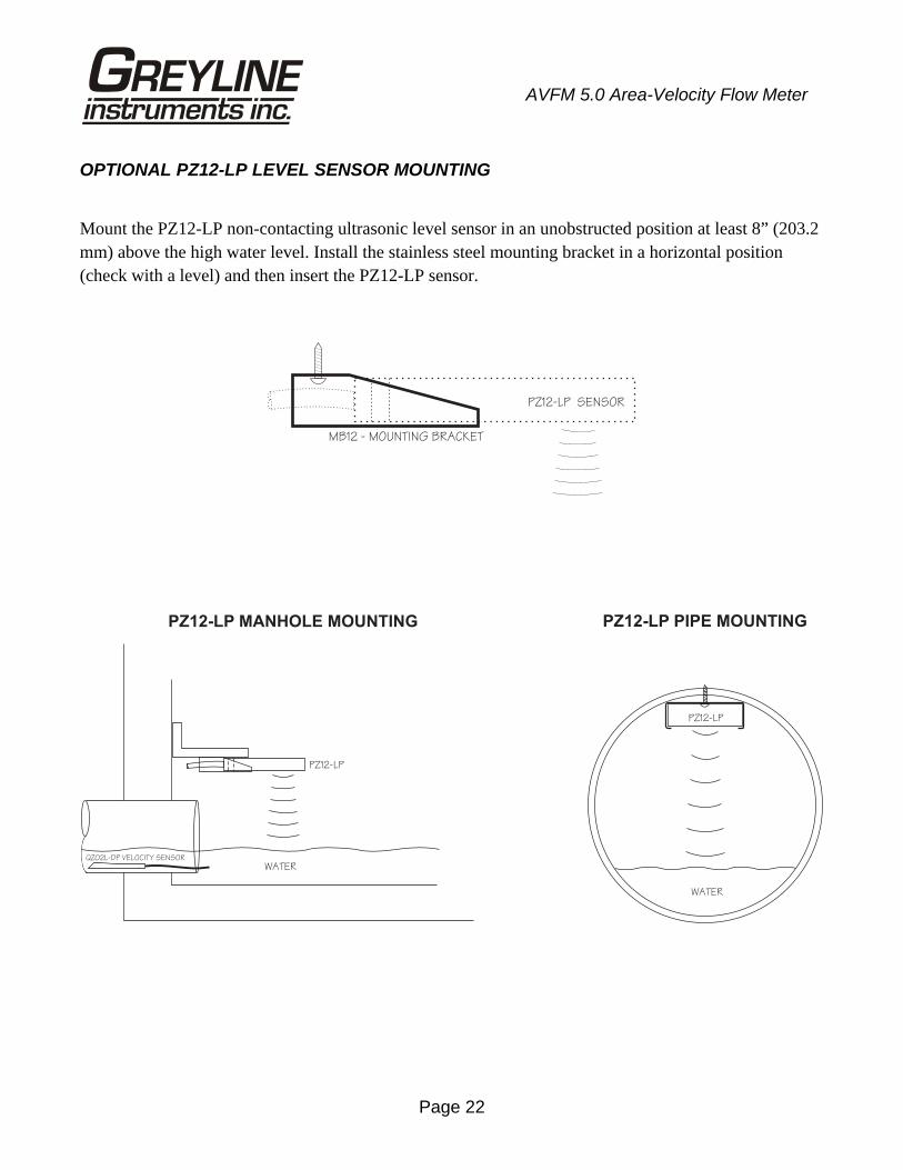
OPTIONAL PZ12-LP LEVEL SENSOR MOUNTING
Mount the PZ12-LP non-contacting ultrasonic level sensor in an unobstructed position at least 8” (203.2 mm) above the high water level. Install the stainless steel mounting bracket in a horizontal position (check with a level) and then insert the PZ12-LP sensor.
PZ12-LP SENSOR
MB12 - MOUNTING BRACKET
WATER
PZ12-LP
PZ12-LP MANHOLE MOUNTING
PZ12-LP
WATER
PZ12-LP PIPE MOUNTING
QZ02L-DP VELOCITY SENSOR
Page 23
AVFM 5.0 Area-Velocity Flow Meter
ENCLOSURE INSTALLATION
Locate the enclosure within 20 ft (6 m) of the sensor (up to 500 ft -150 m optional). The enclosure can be wall mounted with the four mounting screws (included) or panel mounted with Option PM Panel Mount kit from Greyline Instruments.
Avoid mounting the enclosure in direct sunlight to protect the electronics from damage due to overheating and condensate. In high humidity atmospheres, or where temperatures fall below freezing, Option TH Enclosure Heater and Thermostat is recommended. Seal conduit entries to prevent moisture from entering enclosure.
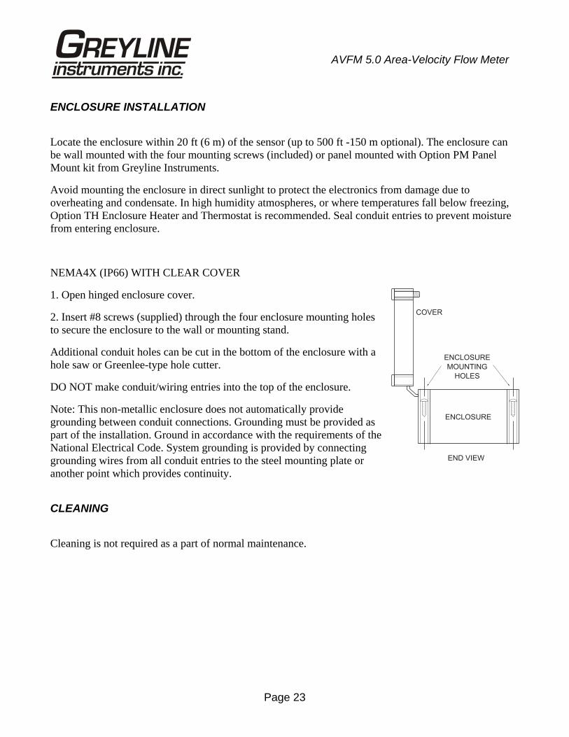
NEMA4X (IP66) WITH CLEAR COVER
1. Open hinged enclosure cover.
2. Insert #8 screws (supplied) through the four enclosure mounting holes to secure the enclosure to the wall or mounting stand.
Additional conduit holes can be cut in the bottom of the enclosure with a hole saw or Greenlee-type hole cutter.
DO NOT make conduit/wiring entries into the top of the enclosure.
Note: This non-metallic enclosure does not automatically provide grounding between conduit connections. Grounding must be provided as part of the installation. Ground in accordance with the requirements of the National Electrical Code. System grounding is provided by connecting grounding wires from all conduit entries to the steel mounting plate or another point which provides continuity.
CLEANING
Cleaning is not required as a part of normal maintenance.
END VIEW
COVER
ENCLOSURE
ENCLOSURE
MOUNTING
HOLES
Page 24
AVFM 5.0 Area-Velocity Flow Meter
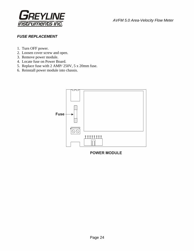
FUSE REPLACEMENT
1. Turn OFF power. 2. Loosen cover screw and open. 3. Remove power module. 4. Locate fuse on Power Board. 5. Replace fuse with 2 AMP/ 250V, 5 x 20mm fuse. 6. Reinstall power module into chassis.
Fuse
POWER MODULE
Page 25
AVFM 5.0 Area-Velocity Flow Meter
FIELD TROUBLESHOOTING
The AVFM 5.0 uses an ultrasonic level sensor to determine channel AREA and an ultrasonic Doppler sensor to measure flow VELOCITY.
The QZ02L sensor combines both sensors in one housing.
An optional configuration uses the PZ12-LP “down-looking” level sensor and a QZ02L-DP velocity sensor.
To troubleshoot the AVFM 5.0, verify correct operation of LEVEL and VELOCITY measurements separately.
Note: Selecting “Defaults” in the SPECIAL FUNCTION menu will return the instrument to “as-shipped” factory settings.
LEVEL (QZ02L SENSOR) SYMPTOMS FAULTS SOLUTIONS EC bar graph at zero - very turbulent flow - Increase LOE time (SPECIAL
FUNCTION) - very aerated flow - relocate sensor or use PZ12-LP - sensor not level - level sensor with “Bullseye” level - sediment/dirt/grease build-up on
sensor - clean sensor with liquid soap
- Level display reads 1.0 inches
- Level at or less than 1.0 inches
VELOCITY (QZ02L SENSOR)
SYMPTOMS FAULTS SOLUTIONS - No velocity reading - Grease/sediment on sensor
- Improper hook-up - Clean sensor with detergent - Check sensor connections
Page 26
AVFM 5.0 Area-Velocity Flow Meter
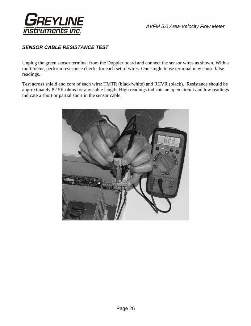
SENSOR CABLE RESISTANCE TEST
Unplug the green sensor terminal from the Doppler board and connect the sensor wires as shown. With a multimeter, perform resistance checks for each set of wires. One single loose terminal may cause false readings.
Test across shield and core of each wire: TMTR (black/white) and RCVR (black). Resistance should be approximately 82.5K ohms for any cable length. High readings indicate an open circuit and low readings indicate a short or partial short in the sensor cable.
Page 27
AVFM 5.0 Area-Velocity Flow Meter
APPLICATIONS HOTLINE
For applications assistance, advice or information on any Greyline Instrument contact your Sales Representative, write to Greyline or phone the Applications Hotline below:
United States: Tel: 315-788-9500 Fax: 315-764-0419 Canada: Tel: 613-938-8956 Fax: 613-938-4857 Toll Free: 888-473-9546 Email: [email protected] Web Site: www.greyline.com
Greyline Instruments Inc. Canada USA: 16456 Sixsmith Drive 105 Water Street Long Sault, Ont. K0C 1P0 Massena, NY 13662
Page 28
AVFM 5.0 Area-Velocity Flow Meter
PRODUCT RETURN PROCEDURE
Instruments may be returned to Greyline for service or warranty repair.
1 Obtain an RMA Number from Greyline - Before shipping a product to the factory please contact Greyline by telephone, fax or email to obtain an RMA number (Returned Merchandise Authorization). This ensures fast service and correct billing or credit.
When you contact Greyline please have the following information available:
1. Model number / Software Version 2. Serial number 3. Date of Purchase 4. Reason for return (description of fault or modification required) 5. Your name, company name, address and phone number
2 Clean the Sensor/Product -
Important: unclean products will not be serviced and will be returned to the sender at their expense.
1. Rinse sensor and cable to remove debris.
2. If the sensor has been exposed to sewage, immerse both sensor and cable in a solution of 1 part household bleach (Javex, Clorox etc.) to 20 parts water for 5 minutes. Important: do not immerse open end of sensor cable.
3. Dry with paper towels and pack sensor and cable in a sealed plastic bag.
4. Wipe the outside of the enclosure to remove dirt or deposits.
5. Return to Greyline for service.
3 Ship to Greyline - After obtaining an RMA number please ship the product to the appropriate address below: Canadian and International USA Customers: Customers: Greyline Instruments Inc. Greyline Instruments Inc. 16456 Sixsmith Drive 204 150th Avenue Long Sault, Ont. K0C 1P0 Madeira Beach, FL 33708
RMA# RMA#
Page 29
AVFM 5.0 Area-Velocity Flow Meter
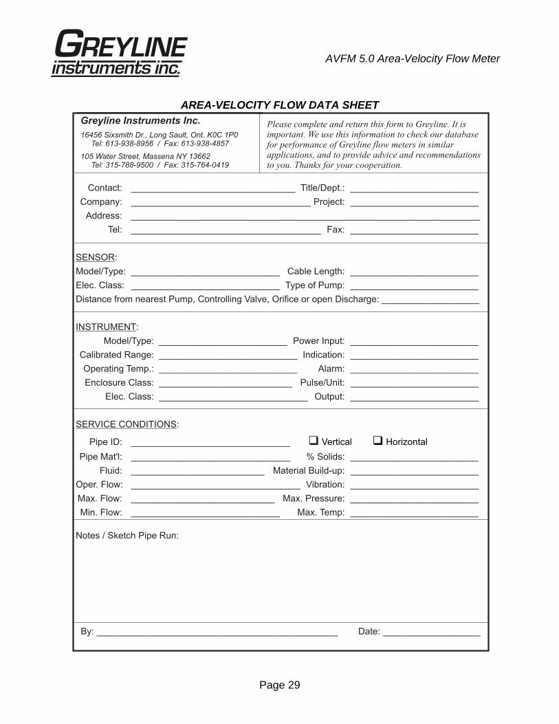
AREA-VELOCITY FLOW DATA SHEET
Greyline Instruments Inc.
16456 Sixsmith Dr., Long Sault, Ont. K0C 1P0Tel: 613-938-8956 / Fax: 613-938-4857
105 Water Street, Massena NY 13662Tel: 315-788-9500 / Fax: 315-764-0419
Please complete and return this form to Greyline. It isimportant. We use this information to check our databasefor performance of Greyline flow meters in similarapplications, and to provide advice and recommendationsto you. Thanks for your cooperation.
Contact: ________________________________ Title/Dept.: _________________________
Company: ___________________________________ Project: _________________________
Address: ____________________________________________________________________
Tel: _____________________________________ Fax: _________________________
:
Model/Type: _____________________________ Cable Length: _________________________
Elec. Class: _____________________________ Type of Pump: _________________________
Distance from nearest Pump, Controlling Valve, Orifice or open Discharge: ___________________
:
Model/Type: _________________________ Power Input: _________________________
Calibrated Range: ___________________________ Indication: _________________________
Operating Temp.: ___________________________ Alarm: _________________________
Enclosure Class: __________________________ Pulse/Unit: _________________________
Elec. Class: _____________________________ Output: _________________________
:
Pipe ID: _______________________________
Pipe Mat'l: _______________________________ % Solids: _________________________
Fluid: __________________________ Material Build-up: _________________________
Oper. Flow: _________________________________ Vibration: _________________________
Max. Flow: ____________________________ Max. Pressure: _________________________
Min. Flow: _____________________________ Max. Temp: _________________________
Notes / Sketch Pipe Run:
By: _______________________________________________ Date: ___________________
SENSOR
INSTRUMENT
SERVICE CONDITIONS
� Vertical � Horizontal
Page 30
AVFM 5.0 Area-Velocity Flow Meter
LIMITED WARRANTY _____________________________________
Greyline Instruments warrants, to the original purchaser, its products to be free from defects in material and workmanship for a period of one year from date of invoice. Greyline will replace or repair, free of charge, any Greyline product if it has been proven to be defective within the warranty period. This warranty does not cover any expenses incurred in the removal and re-installation of the product.
If a product manufactured by Greyline should prove defective within the first year, return it freight prepaid to Greyline Instruments along with a copy of your invoice.
This warranty does not cover damages due to improper installation or handling, acts of nature, or unauthorized service. Modifications to or tampering with any part shall void this warranty. This warranty does not cover any equipment used in connection with the product or consequential damages due to a defect in the product.
All implied warranties are limited to the duration of this warranty. This is the complete warranty by Greyline and no other warranty is valid against Greyline. Some states do not allow limitations on how long an implied warranty lasts or limitation of incidental or consequential damages, so the above limitations or exclusions may not apply to you.
This warranty gives you specific legal rights, and you may also have other rights which vary from state to state.
Greyline Instruments Inc.
Page 31
AVFM 5.0 Area-Velocity Flow Meter
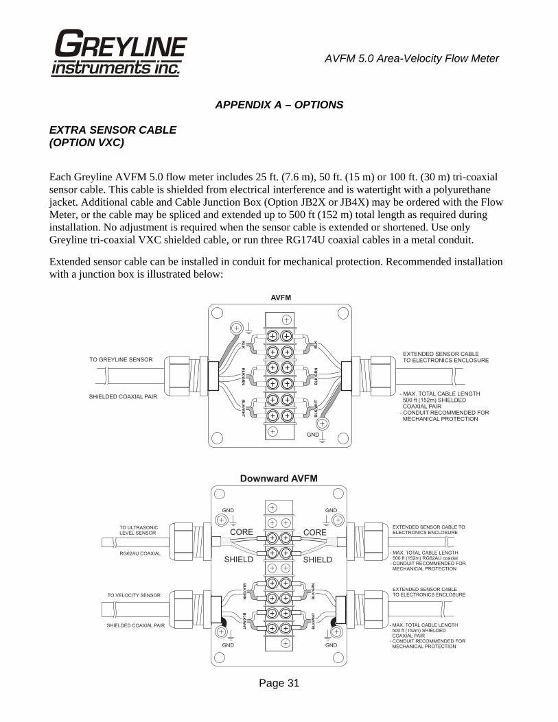
APPENDIX A – OPTIONS EXTRA SENSOR CABLE (OPTION VXC)
Each Greyline AVFM 5.0 flow meter includes 25 ft. (7.6 m), 50 ft. (15 m) or 100 ft. (30 m) tri-coaxial sensor cable. This cable is shielded from electrical interference and is watertight with a polyurethane jacket. Additional cable and Cable Junction Box (Option JB2X or JB4X) may be ordered with the Flow Meter, or the cable may be spliced and extended up to 500 ft (152 m) total length as required during installation. No adjustment is required when the sensor cable is extended or shortened. Use only Greyline tri-coaxial VXC shielded cable, or run three RG174U coaxial cables in a metal conduit.
Extended sensor cable can be installed in conduit for mechanical protection. Recommended installation with a junction box is illustrated below:
RG62AU COAXIAL - MAX. TOTAL CABLE LENGTH500 ft (152m) RG62AU coaxial
- CONDUIT RECOMMENDED FORMECHANICAL PROTECTION
EXTENDED SENSOR CABLE TOELECTRONICS ENCLOSURE
TO ULTRASONICLEVEL SENSOR
TO VELOCITY SENSOR
SHIELDED COAXIAL PAIR - MAX. TOTAL CABLE LENGTH500 ft (152m) SHIELDEDCOAXIAL PAIR
- CONDUIT RECOMMENDED FORMECHANICAL PROTECTION
EXTENDED SENSOR CABLETO ELECTRONICS ENCLOSURE
Downward AVFM
GND GND
GND GND
CORE
SHIELD
CORE
SHIELD
BL
K/W
HT
BL
K/G
RN
BL
K/W
HT
BL
K/G
RN
- MAX. TOTAL CABLE LENGTH500 ft (152m) SHIELDEDCOAXIAL PAIR
- CONDUIT RECOMMENDED FORMECHANICAL PROTECTION
TO GREYLINE SENSOREXTENDED SENSOR CABLETO ELECTRONICS ENCLOSURE
SHIELDED COAXIAL PAIR
GND
BL
KB
LK
/GR
NB
LK
/WH
TB
LK
BL
K/W
HT
BL
K/G
RN
AVFM
Page 32
AVFM 5.0 Area-Velocity Flow Meter
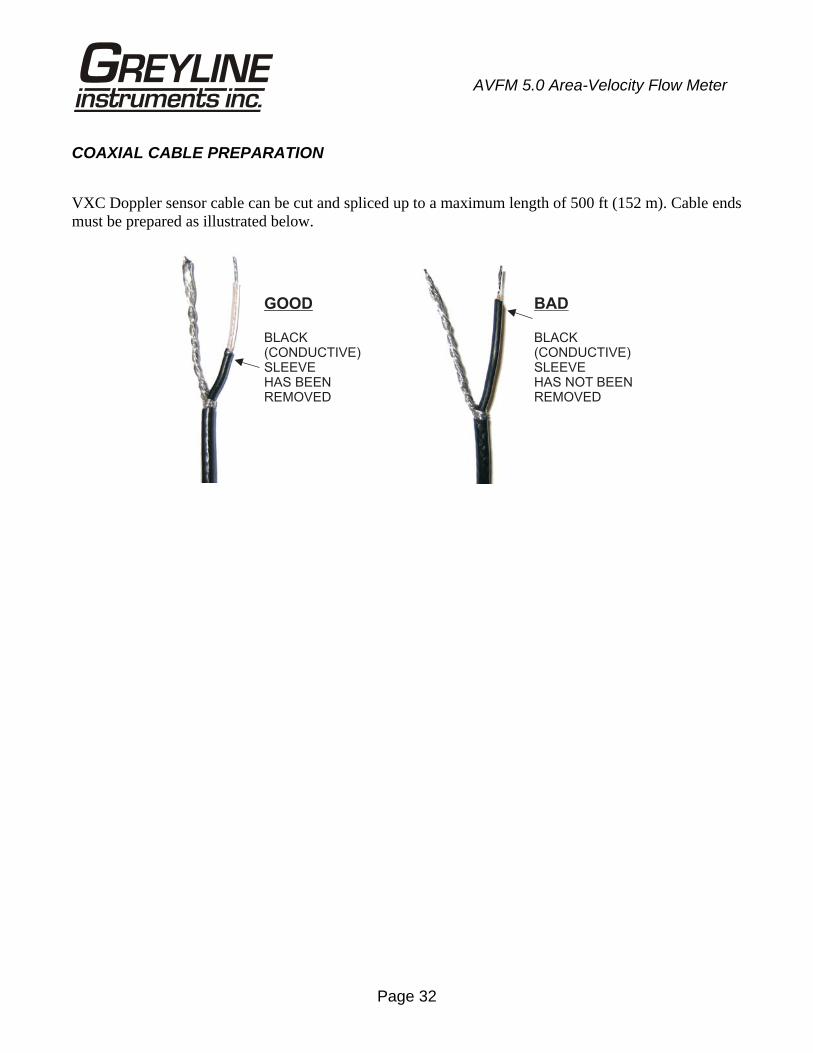
COAXIAL CABLE PREPARATION
VXC Doppler sensor cable can be cut and spliced up to a maximum length of 500 ft (152 m). Cable ends must be prepared as illustrated below.
GOOD
BLACK(CONDUCTIVE)SLEEVEHAS BEENREMOVED
BAD
BLACK(CONDUCTIVE)SLEEVEHAS NOT BEENREMOVED
Page 33
AVFM 5.0 Area-Velocity Flow Meter
JUNCTION BOX - OPTION JB2X & JB4X
NEMA4X (IP66) polycarbonate Junction Box with terminal strips is available from Greyline Instruments. Includes compression fittings for watertight coaxial cable entries.
Page 34
AVFM 5.0 Area-Velocity Flow Meter
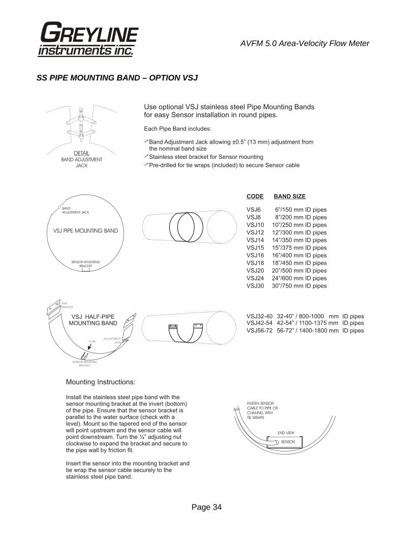
SS PIPE MOUNTING BAND – OPTION VSJ
CODE BAND SIZE
VSJ6 6”/150 mm ID pipes
VSJ8 8”/200 mm ID pipes
VSJ10 10”/250 mm ID pipes
VSJ12 12”/300 mm ID pipes
VSJ14 14”/350 mm ID pipes
VSJ15 15”/375 mm ID pipes
VSJ16 16”/400 mm ID pipes
VSJ18 18”/450 mm ID pipes
VSJ20 20”/500 mm ID pipes
VSJ24 24”/600 mm ID pipes
VSJ30 30”/750 mm ID pipes
VSJ32-40 32-40” / 800-1000 mm ID pipesVSJ42-54 42-54” / 1100-1375 mm ID pipes
VSJ56-72 56-72” / 1400-1800 mm ID pipes
DETAILBAND ADJUSTMENT
JACK
Use optional VSJ stainless steel Pipe Mounting Bandsfor easy Sensor installation in round pipes.
Each Pipe Band includes:
Band Adjustment Jack allowing ±0.5” (13 mm) adjustment fromthe nominal band size
Stainless steel bracket for Sensor mounting
Pre-drilled for tie wraps (included) to secure Sensor cable
�
�
�
VSJ PIPE MOUNTING BAND
BAND
ADJUSTMENT JACK
SENSOR MOUNTING
BRACKET
Mounting Instructions:
Install the stainless steel pipe band with thesensor mounting bracket at the invert (bottom)of the pipe. Ensure that the sensor bracket isparallel to the water surface (check with alevel). Mount so the tapered end of the sensorwill point upstream and the sensor cable willpoint downstream. Turn the ¼” adjusting nutclockwise to expand the bracket and secure tothe pipe wall by friction fit.
Insert the sensor into the mounting bracket andtie wrap the sensor cable securely to thestainless steel pipe band.
FASTEN SENSOR
CABLE TO PIPE OR
CHANNEL WITH
TIE WRAPS
SENSOR
END VIEW
VSJ HALF-PIPEMOUNTING BAND
ADJUSTMENT
JACK
SENSOR MOUNTING
BRACKET
END
BRACKET
FLOW
Page 35
AVFM 5.0 Area-Velocity Flow Meter
SENSOR INTRINSIC SAFETY
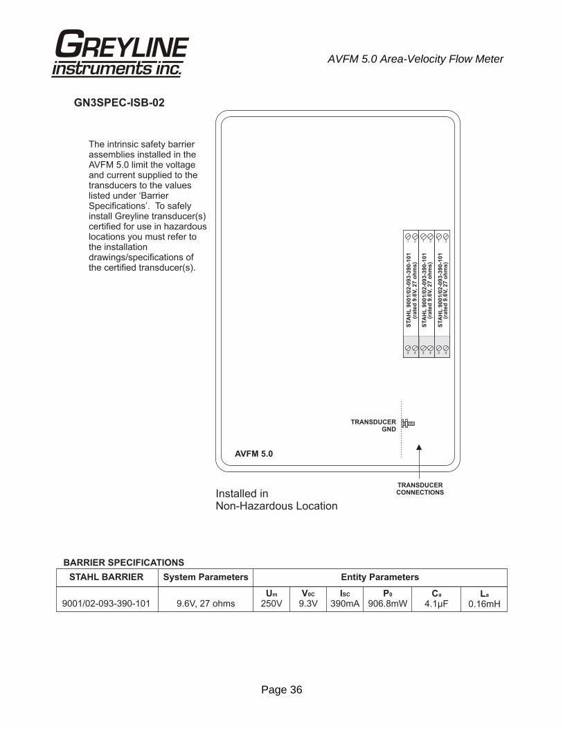
When connected through Intrinsic Safety Barriers, the Greyline Sensor Model QZ02L and PZ series are CSA certified for installation in a hazardous location rated:
Class I, Groups C,D Class II, Groups E,F,G Class III Intrinsic Safety Barriers may be ordered with the Greyline instrument and are supplied mounted in the Greyline instrument enclosure. Replacement barrier fuses (Part No. ISB- 011239) may be purchased separately. The instrument enclosure containing the Intrinsic Safety Barriers must be installed in a non-hazardous location.
Page 36
AVFM 5.0 Area-Velocity Flow Meter
TRANSDUCERGND
AVFM 5.0
STA
HL
9001/0
2-0
93-3
90-1
01
1 2
3 4
STA
HL
9001/0
2-0
93-3
90-1
01
1 2
3 4
Installed inNon-Hazardous Location
The intrinsic safety barrierassemblies installed in theAVFM 5.0 limit the voltageand current supplied to thetransducers to the valueslisted under ‘BarrierSpecifications’. To safelyinstall Greyline transducer(s)certified for use in hazardouslocations you must refer tothe installationdrawings/specifications ofthe certified transducer(s).
TRANSDUCERCONNECTIONS
STA
HL
9001/0
2-0
93-3
90-1
01
1 2
3 4
BARRIER SPECIFICATIONS
9001/02-093-390-101
STAHL BARRIER
9.6V, 27 ohmsUm
250VV0C
9.3VISC
390mAP0
906.8mWCa
4.1µFLa
0.16mH
System Parameters Entity Parameters
GN3SPEC-ISB-02
(rate
d 9
.6V
, 27 o
hm
s)
(rate
d 9
.6V
, 27 o
hm
s)
(rate
d 9
.6V
, 27 o
hm
s)
Page 37
AVFM 5.0 Area-Velocity Flow Meter
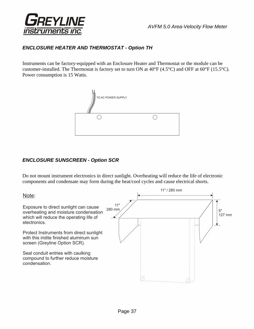
ENCLOSURE HEATER AND THERMOSTAT - Option TH
Instruments can be factory-equipped with an Enclosure Heater and Thermostat or the module can be customer-installed. The Thermostat is factory set to turn ON at 40°F (4.5°C) and OFF at 60°F (15.5°C). Power consumption is 15 Watts.
ENCLOSURE SUNSCREEN - Option SCR
Do not mount instrument electronics in direct sunlight. Overheating will reduce the life of electronic components and condensate may form during the heat/cool cycles and cause electrical shorts.
TO AC POWER SUPPLY
Note:
Exposure to direct sunlight can causeoverheating and moisture condensationwhich will reduce the operating life ofelectronics.
Protect Instruments from direct sunlightwith this iridite finished aluminum sunscreen (Greyline Option SCR).
Seal conduit entries with caulkingcompound to further reduce moisturecondensation.
11" / 280 mm
5"127 mm
11"280 mm
Page 38
AVFM 5.0 Area-Velocity Flow Meter
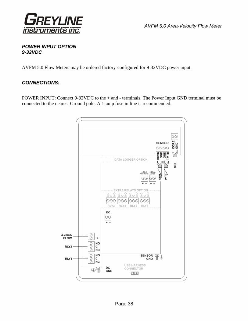
POWER INPUT OPTION 9-32VDC
AVFM 5.0 Flow Meters may be ordered factory-configured for 9-32VDC power input.
CONNECTIONS:
POWER INPUT: Connect 9-32VDC to the + and - terminals. The Power Input GND terminal must be connected to the nearest Ground pole. A 1-amp fuse in line is recommended.
DATA LOGGER OPTION
NOCNC
NOCNC
–+
RLY2
RLY1
NC
C NO
NC
C NO
NC
C NO
NC
C NO
RLY3 RLY4 RLY5 RLY6
EXTRA RELAYS OPTION
RC
VR
GN
DG
ND
TM
TR
GR
N
WH
T
DC
+ –
SENSOR
4-20mAFLOW
4-20mAVELOCITY
4-20mALEVEL
SENSORGND
USB HARNESSCONNECTOR
+ +– –
CO
RE
GN
DB
LK
DCGND
Page 39
AVFM 5.0 Area-Velocity Flow Meter
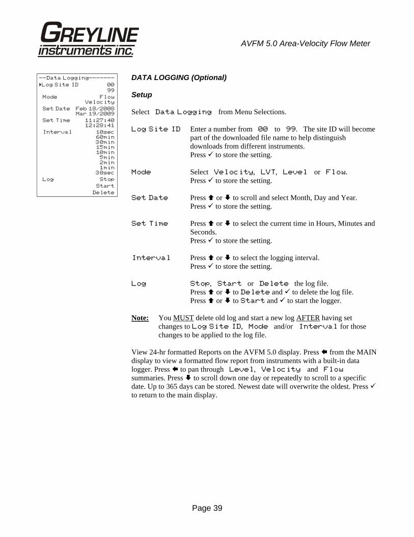
DATA LOGGING (Optional) Setup Select Data Logging from Menu Selections. Log Site ID Enter a number from 00 to 99. The site ID will become
part of the downloaded file name to help distinguish downloads from different instruments.
Press to store the setting. Mode Select Velocity, LVT, Level or Flow. Press to store the setting. Set Date Press or to scroll and select Month, Day and Year. Press to store the setting. Set Time Press or to select the current time in Hours, Minutes and
Seconds. Press to store the setting. Interval Press or to select the logging interval. Press to store the setting. Log Stop, Start or Delete the log file. Press or to Delete and to delete the log file. Press or to Start and to start the logger. Note: You MUST delete old log and start a new log AFTER having set
changes to Log Site ID, Mode and/or Interval for those changes to be applied to the log file.
View 24-hr formatted Reports on the AVFM 5.0 display. Press from the MAIN display to view a formatted flow report from instruments with a built-in data logger. Press to pan through Level, Velocity and Flow summaries. Press to scroll down one day or repeatedly to scroll to a specific date. Up to 365 days can be stored. Newest date will overwrite the oldest. Press to return to the main display.
--Data Logging-------
Log Site ID 00
99
Mode FlowVelocity
Set Date Feb 18/2008Mar 19/2009
Set Time 11:27:4012:28:41
Interval 10sec60min30min15min10min
5min2min1min
30sec
Log Stop
Start
Delete
�
Page 40
AVFM 5.0 Area-Velocity Flow Meter
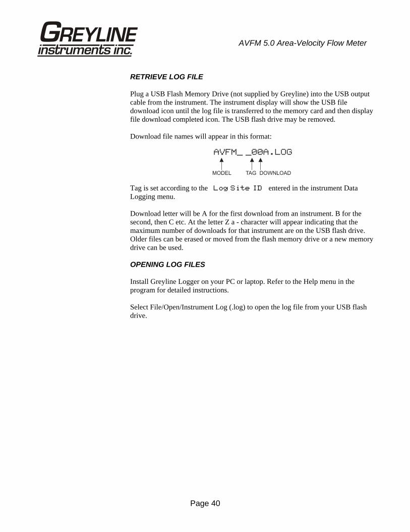
RETRIEVE LOG FILE Plug a USB Flash Memory Drive (not supplied by Greyline) into the USB output cable from the instrument. The instrument display will show the USB file download icon until the log file is transferred to the memory card and then display file download completed icon. The USB flash drive may be removed. Download file names will appear in this format:
Tag is set according to the Log Site ID entered in the instrument Data Logging menu. Download letter will be A for the first download from an instrument. B for the second, then C etc. At the letter Z a - character will appear indicating that the maximum number of downloads for that instrument are on the USB flash drive. Older files can be erased or moved from the flash memory drive or a new memory drive can be used.
OPENING LOG FILES Install Greyline Logger on your PC or laptop. Refer to the Help menu in the program for detailed instructions. Select File/Open/Instrument Log (.log) to open the log file from your USB flash drive.
AVFM_ _00A.LOG
MODEL TAG DOWNLOAD
Page 41
AVFM 5.0 Area-Velocity Flow Meter
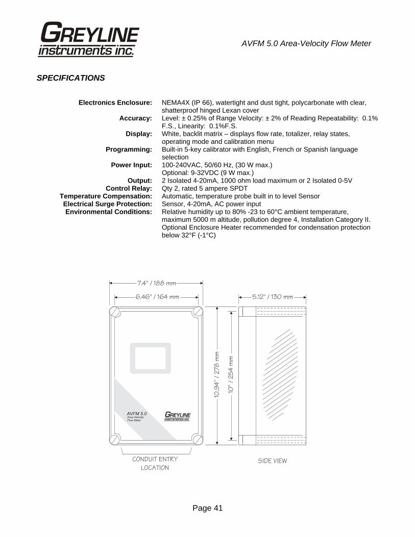
SPECIFICATIONS
Electronics Enclosure: NEMA4X (IP 66), watertight and dust tight, polycarbonate with clear, shatterproof hinged Lexan cover
Accuracy: Level: ± 0.25% of Range Velocity: ± 2% of Reading Repeatability: 0.1% F.S., Linearity: 0.1%F.S.
Display: White, backlit matrix – displays flow rate, totalizer, relay states, operating mode and calibration menu
Programming: Built-in 5-key calibrator with English, French or Spanish language selection
Power Input: 100-240VAC, 50/60 Hz, (30 W max.) Optional: 9-32VDC (9 W max.) Output: 2 Isolated 4-20mA, 1000 ohm load maximum or 2 Isolated 0-5V Control Relay: Qty 2, rated 5 ampere SPDT Temperature Compensation: Automatic, temperature probe built in to level Sensor Electrical Surge Protection: Sensor, 4-20mA, AC power input Environmental Conditions: Relative humidity up to 80% -23 to 60°C ambient temperature,
maximum 5000 m altitude, pollution degree 4, Installation Category II. Optional Enclosure Heater recommended for condensation protection below 32°F (-1°C)
7.4 / 188 mm"
6.46 / 164 mm"
10.9
4"
/2
78
mm
10/
25
4m
m"
CONDUIT ENTRY
LOCATIONSIDE VIEW
5.12 / 130 mm"
AVFM 5.0Area-VelocityFlow Meter
Page 42
AVFM 5.0 Area-Velocity Flow Meter
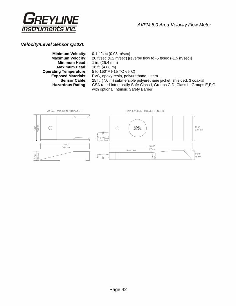
Velocity/Level Sensor QZ02L Minimum Velocity: 0.1 ft/sec (0.03 m/sec) Maximum Velocity: 20 ft/sec (6.2 m/sec) [reverse flow to -5 ft/sec (-1.5 m/sec)] Minimum Head: 1 in. (25.4 mm) Maximum Head: 16 ft. (4.88 m) Operating Temperature: 5 to 150°F (-15 TO 65°C) Exposed Materials: PVC, epoxy resin, polyurethane, ultem Sensor Cable: 25 ft. (7.6 m) submersible polyurethane jacket, shielded, 3 coaxial Hazardous Rating: CSA rated Intrinsically Safe Class I, Groups C,D, Class II, Groups E,F,G
with optional Intrinsic Safety Barrier
1.6
2"
41.
2m
m
0.5
6"
14.2
mm
3.00"
76.2 mm
MB-QZ - MOUNTING BRACKET QZ02L VELOCITY/LEVEL SENSOR
25 ft (7.6 m)Sensor Cable
5.00”
127 mm
1.50
38.1 mm
"
0.63"
16 mm
SIDE VIEW0
.50
"
12.7
mm
LEVEL
SENSOR
Page 43
AVFM 5.0 Area-Velocity Flow Meter
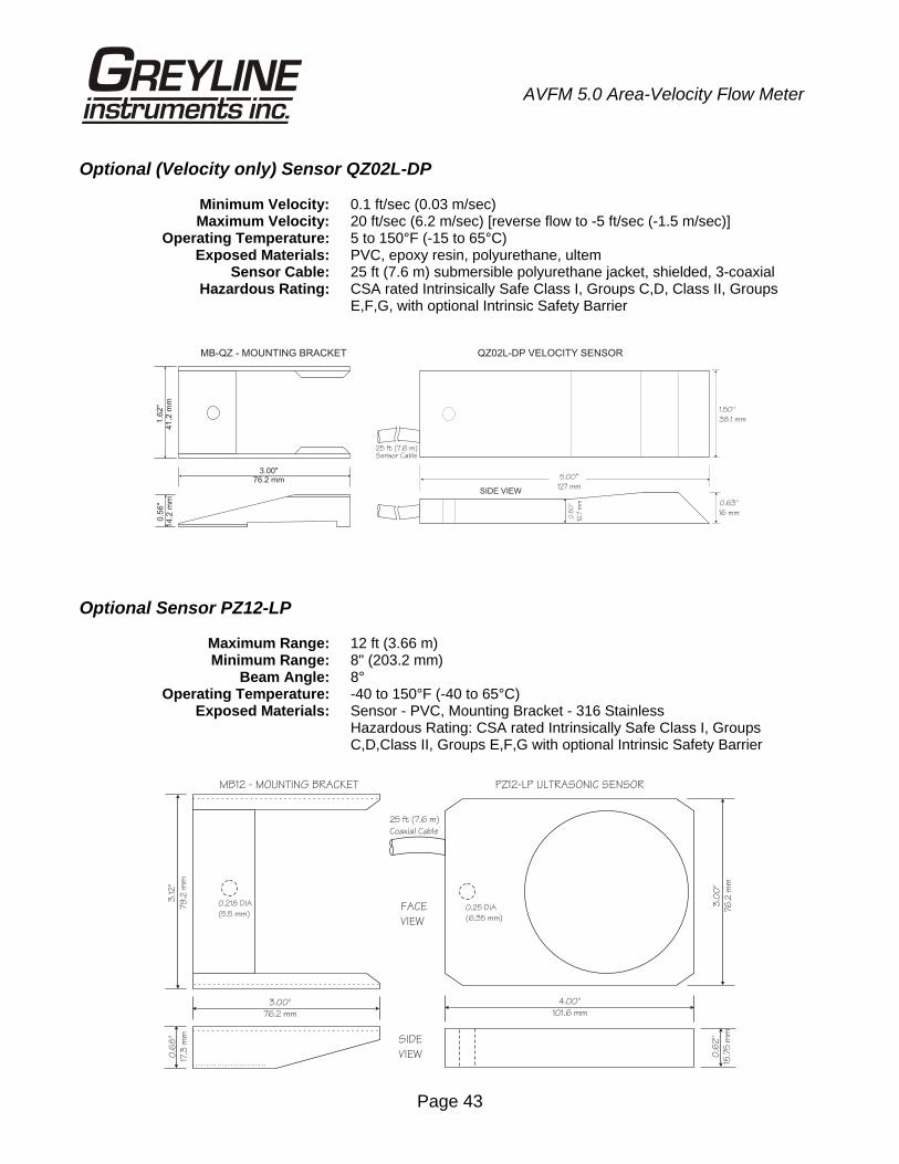
Optional (Velocity only) Sensor QZ02L-DP Minimum Velocity: 0.1 ft/sec (0.03 m/sec) Maximum Velocity: 20 ft/sec (6.2 m/sec) [reverse flow to -5 ft/sec (-1.5 m/sec)] Operating Temperature: 5 to 150°F (-15 to 65°C) Exposed Materials: PVC, epoxy resin, polyurethane, ultem Sensor Cable: 25 ft (7.6 m) submersible polyurethane jacket, shielded, 3-coaxial Hazardous Rating: CSA rated Intrinsically Safe Class I, Groups C,D, Class II, Groups
E,F,G, with optional Intrinsic Safety Barrier
Optional Sensor PZ12-LP Maximum Range: 12 ft (3.66 m) Minimum Range: 8" (203.2 mm) Beam Angle: 8° Operating Temperature: -40 to 150°F (-40 to 65°C) Exposed Materials: Sensor - PVC, Mounting Bracket - 316 Stainless Hazardous Rating: CSA rated Intrinsically Safe Class I, Groups
C,D,Class II, Groups E,F,G with optional Intrinsic Safety Barrier
QZ02L-DP VELOCITY SENSOR
25 ft (7.6 m)Sensor Cable
5.00”
127 mm
1.50
38.1 mm
"
0.63"
16 mm
SIDE VIEW
0.5
0"
12.7
mm
1.6
2"
41.2
mm
0.5
6"
14.2
mm
3.00"76.2 mm
MB-QZ - MOUNTING BRACKET
4.00"
101.6 mm
3.0
0"
76
.2m
m
0.6
2"
15.7
5m
m
FACE
VIEW
SIDE
VIEW
0.25 DIA
(6.35 mm)
MB12 - MOUNTING BRACKET PZ12-LP ULTRASONIC SENSOR
0.218 DIA
(5.5 mm)
3.00"
76.2 mm
0.6
8"
17.3
mm
3.1
2"
79
.2m
m
25 ft (7.6 m)
Coaxial Cable
Page 44
AVFM 5.0 Area-Velocity Flow Meter
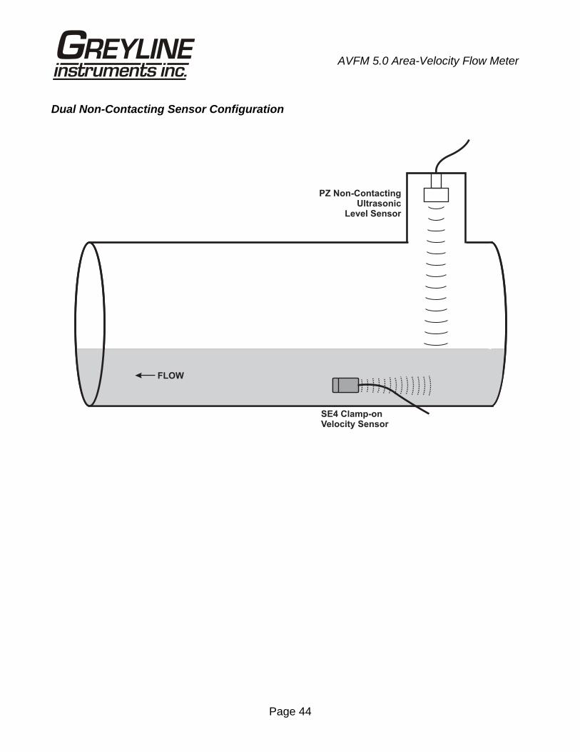
Dual Non-Contacting Sensor Configuration
PZ Non-ContactingUltrasonic
Level Sensor
SE4 Clamp-onVelocity Sensor
FLOW
Page 45
AVFM 5.0 Area-Velocity Flow Meter
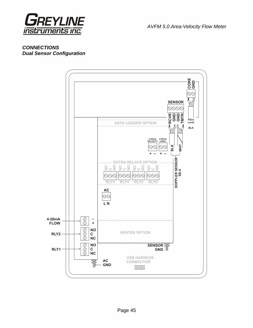
CONNECTIONS Dual Sensor Configuration
SENSOR
HEATER OPTION
AC
L N
NOCNC
NOCNC
–+
4-20mAFLOW
RLY2
RLY1
ACGND
SENSORGND
NC
C NO
NC
C NO
NC
C NO
NC
C NO
RLY3 RLY4 RLY5 RLY6
EXTRA RELAYS OPTION
4-20mAVELOCITY
4-20mALEVEL
DATA LOGGER OPTION
USB HARNESSCONNECTOR
+ +– –
RC
VR
GN
DG
ND
TM
TR
CO
RE
GN
D
BL
K
WH
T
DO
PP
LE
R S
EN
SO
RS
E-4
PZxxLevel
BLK
Page 46
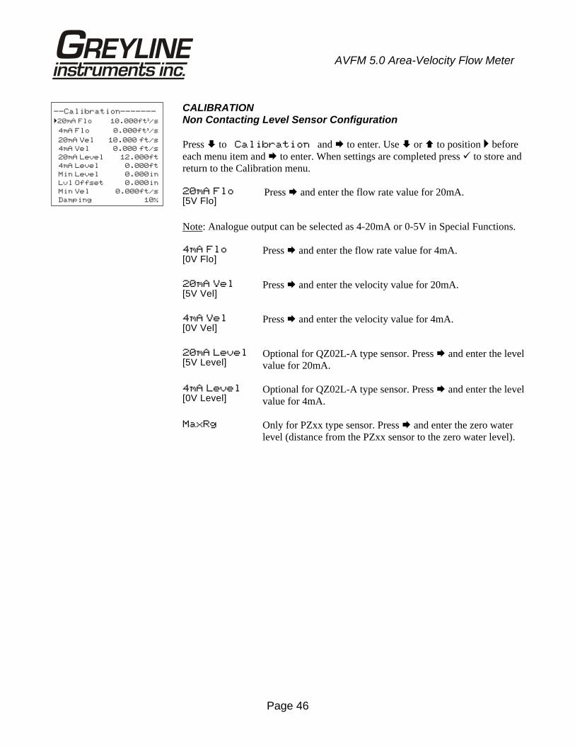
AVFM 5.0 Area-Velocity Flow Meter
CALIBRATION Non Contacting Level Sensor Configuration Press to Calibration and to enter. Use or to position before each menu item and to enter. When settings are completed press to store and return to the Calibration menu. 20mA Flo[5V Flo]
Press and enter the flow rate value for 20mA.
Note: Analogue output can be selected as 4-20mA or 0-5V in Special Functions. 4mA Flo [0V Flo]
Press and enter the flow rate value for 4mA.
20mA Vel[5V Vel]
Press and enter the velocity value for 20mA.
4mA Vel [0V Vel]
Press and enter the velocity value for 4mA.
20mA Level[5V Level]
Optional for QZ02L-A type sensor. Press and enter the level value for 20mA.
4mA Level[0V Level]
Optional for QZ02L-A type sensor. Press and enter the level value for 4mA.
MaxRg Only for PZxx type sensor. Press and enter the zero water level (distance from the PZxx sensor to the zero water level).
--Calibration-------
�20mA Flo 10.000ft /s³
4mA Flo 0.000ft /s³
20mA Vel 10.000 ft/s
4mA Vel 0.000 ft/s
20mA Level 12.000ft
4mA Level 0.000ft
Min Level 0.000in
Lvl Offset 0.000in
Min Vel 0.000ft/s
Damping 10%
Page 47
AVFM 5.0 Area-Velocity Flow Meter
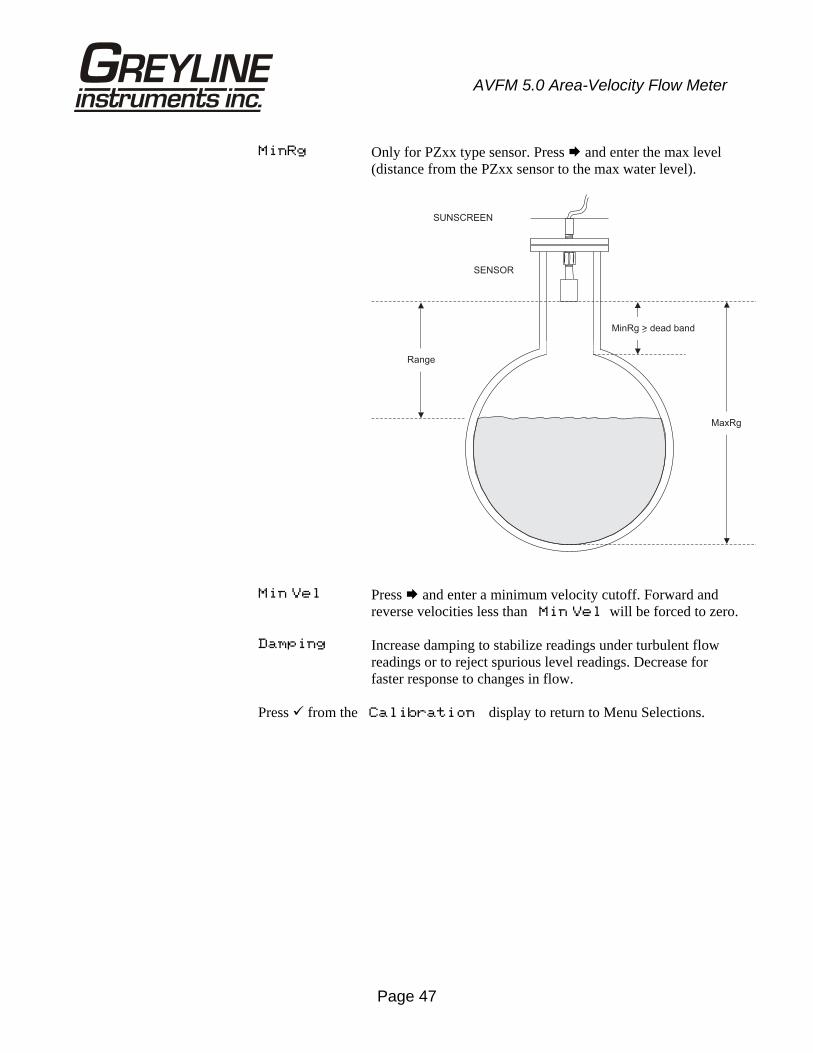
MinRg Only for PZxx type sensor. Press and enter the max level (distance from the PZxx sensor to the max water level).
Min Vel Press and enter a minimum velocity cutoff. Forward and
reverse velocities less than Min Vel will be forced to zero.
Damping Increase damping to stabilize readings under turbulent flow readings or to reject spurious level readings. Decrease for faster response to changes in flow.
Press from the Calibration display to return to Menu Selections.
SUNSCREEN
SENSOR
MaxRg
Range
MinRg > dead band
Page 48
AVFM 5.0 Area-Velocity Flow Meter
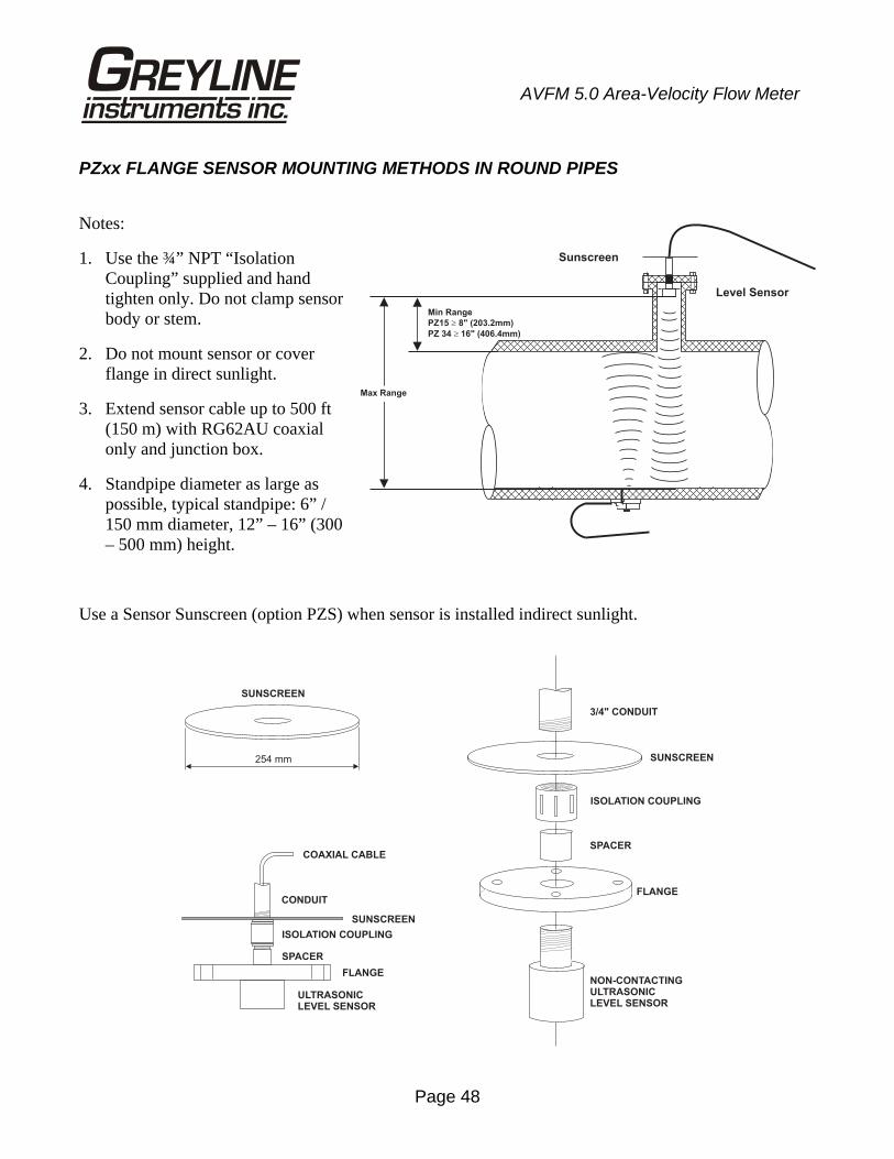
PZxx FLANGE SENSOR MOUNTING METHODS IN ROUND PIPES
Notes:
1. Use the ¾” NPT “Isolation Coupling” supplied and hand tighten only. Do not clamp sensor body or stem.
2. Do not mount sensor or cover flange in direct sunlight.
3. Extend sensor cable up to 500 ft (150 m) with RG62AU coaxial only and junction box.
4. Standpipe diameter as large as possible, typical standpipe: 6” / 150 mm diameter, 12” – 16” (300 – 500 mm) height.
Use a Sensor Sunscreen (option PZS) when sensor is installed indirect sunlight.
Sunscreen
Min Range
PZ15 8" (203.2mm)�
PZ 34 16" (406.4mm)��
Level Sensor
Max Range
CONDUIT
254 mm
SUNSCREEN
SUNSCREEN
ISOLATION COUPLING
FLANGE
SPACER
NON-CONTACTINGULTRASONICLEVEL SENSOR
ULTRASONICLEVEL SENSOR
SUNSCREEN
3/4" CONDUIT
FLANGE
ISOLATION COUPLING
SPACER
COAXIAL CABLE
Page 49
AVFM 5.0 Area-Velocity Flow Meter
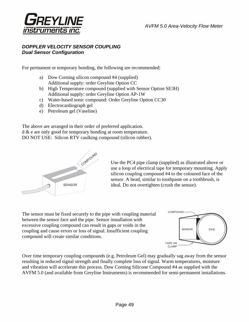
DOPPLER VELOCITY SENSOR COUPLING Dual Sensor Configuration
For permanent or temporary bonding, the following are recommended:
a) Dow Corning silicon compound #4 (supplied) Additional supply: order Greyline Option CC b) High Temperature compound (supplied with Sensor Option SE3H) Additional supply: order Greyline Option AP-1W c) Water-based sonic compound: Order Greyline Option CC30 d) Electrocardiograph gel e) Petroleum gel (Vaseline)
The above are arranged in their order of preferred application. d & e are only good for temporary bonding at room temperature. DO NOT USE: Silicon RTV caulking compound (silicon rubber).
Use the PC4 pipe clamp (supplied) as illustrated above or use a loop of electrical tape for temporary mounting. Apply silicon coupling compound #4 to the coloured face of the sensor. A bead, similar to toothpaste on a toothbrush, is ideal. Do not overtighten (crush the sensor).
The sensor must be fixed securely to the pipe with coupling material between the sensor face and the pipe. Sensor installation with excessive coupling compound can result in gaps or voids in the coupling and cause errors or loss of signal. Insufficient coupling compound will create similar conditions.
Over time temporary coupling compounds (e.g. Petroleum Gel) may gradually sag away from the sensor resulting in reduced signal strength and finally complete loss of signal. Warm temperatures, moisture and vibration will accelerate this process. Dow Corning Silicone Compound #4 as supplied with the AVFM 5.0 (and available from Greyline Instruments) is recommended for semi-permanent installations.
COM
POUND
SENSOR
TAPE OR
CLAMP
COMPOUND
PIPESENSOR
Page 50
AVFM 5.0 Area-Velocity Flow Meter
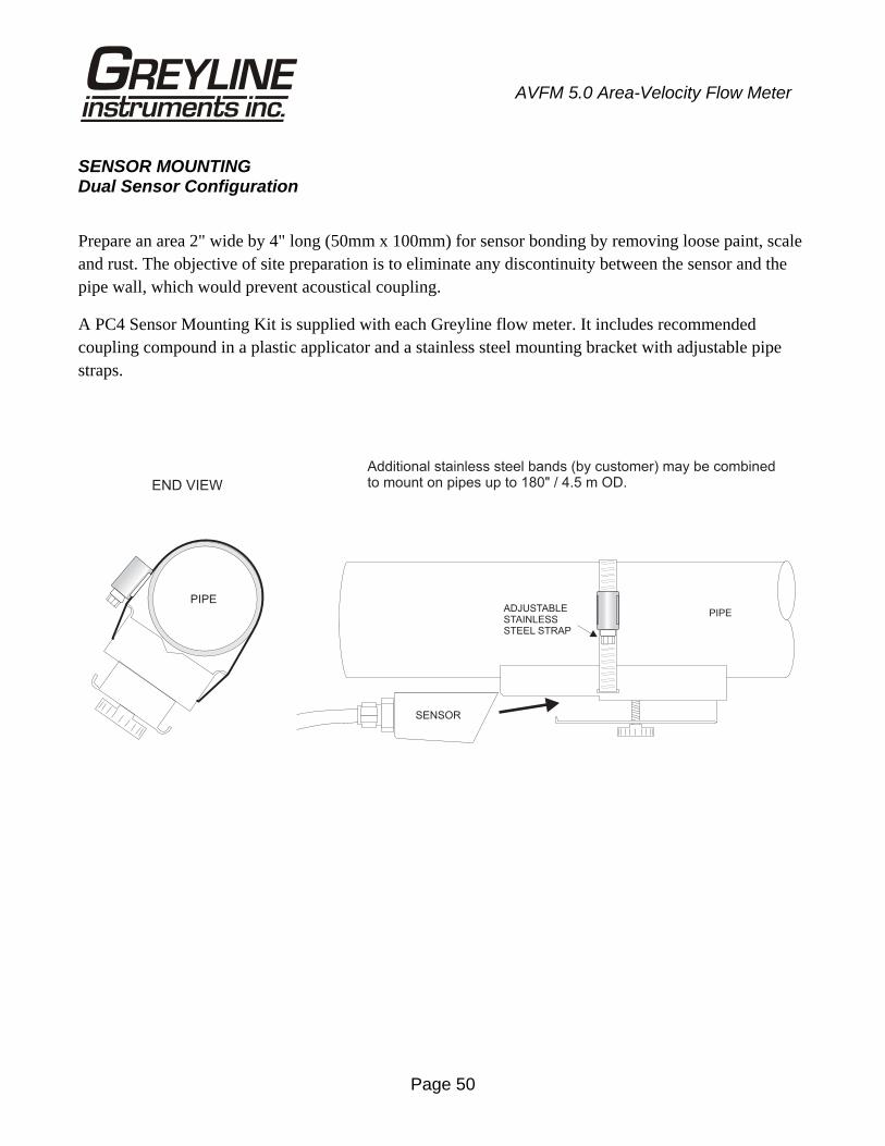
SENSOR MOUNTING Dual Sensor Configuration
Prepare an area 2" wide by 4" long (50mm x 100mm) for sensor bonding by removing loose paint, scale and rust. The objective of site preparation is to eliminate any discontinuity between the sensor and the pipe wall, which would prevent acoustical coupling.
A PC4 Sensor Mounting Kit is supplied with each Greyline flow meter. It includes recommended coupling compound in a plastic applicator and a stainless steel mounting bracket with adjustable pipe straps.
Additional stainless steel bands (by customer) may be combinedto mount on pipes up to 180" / 4.5 m OD.END VIEW
SENSOR
ADJUSTABLESTAINLESSSTEEL STRAP
PIPE
PIPE