Embed Size (px)
Citation preview

User’s Guide
Model PX751 Pressure Transmitter
http://www.omega.come-mail: [email protected]
PX751Pressure Transmitter

OMEGAnet® On-Line Service Internet e-mailhttp://www.omega.com [email protected]
Servicing North America:USA: One Omega Drive, Box 4047ISO 9001 Certified Stamford, CT 06907-0047Tel: (203) 359-1660 FAX: (203) 359-7700e-mail: [email protected]: 976 Bergar
Laval (Quebec) H7L 5A1Tel: (514) 856-6928 FAX: (514) 856-6886e-mail: [email protected]
For immediate technical or application assistance:USA and Canada: Sales Service: 1-800-826-6342 / 1-800-TC-OMEGASMCustomer Service: 1-800-622-2378 / 1-800-622-BESTSMEngineering Service: 1-800-872-9436 / 1-800-USA-WHENSMTELEX: 996404 EASYLINK: 62968934 CABLE: OMEGAMexico andLatin America: Tel: (95) 800-826-6342 FAX: (95) 203-359-7807
En Espan˜ol: (95) 203-359-7803 e-mail: [email protected]
Servicing Europe:Benelux: Postbus 8034, 1180 LA Amstelveen, The NetherlandsTel: (31) 20 6418405 FAX: (31) 20 6434643
Toll Free in Benelux: 0800 0993344e-mail: [email protected]
Czech Republic: ul. Rude armady 1868, 733 01 Karvina-HraniceTel: 420 (69) 6311899 FAX: 420 (69) 6311114
Toll Free: 0800-1-66342 e-mail: [email protected]: 9, rue Denis Papin, 78190 TrappesTel: (33) 130-621-400 FAX: (33) 130-699-120Toll Free in France: 0800-4-06342
e-mail: [email protected]/Austria: Daimlerstrasse 26, D-75392 Deckenpfronn, GermanyTel: 49 (07056) 3017 FAX: 49 (07056) 8540Toll Free in Germany: 0130 11 21 66
e-mail: [email protected] Kingdom: One Omega Drive, River Bend Technology Centre ISO 9002 Certified Northbank, Irlam, Manchester
M44 5EX, EnglandTel: 44 (161) 777-6611 FAX: 44 (161) 777-6622Toll Free in the United Kingdom: 0800-488-488e-mail: [email protected]
It is the policy of OMEGA to comply with all worldwide safety and EMC/EMI regulations that apply. OMEGA is constantly pursuing certification ofits products to the European New Approach Directives. OMEGA will add the CE mark to every appropriate device upon certification.The information contained in this document is believed to be correct, but OMEGA Engineering, Inc. acceptsno liability for any errors it contains, and reserves the right to alter specifications without notice.WARNING: These products are not designed for use in, and should not be used for, patient-connected applications.
Table of Contents
i
EN
SECTION 1 IntroductionOverview . . . . . . . . . . . . . . . . . . . . . . . . . . . . . . . . . . . . . . . . . . . . . . . . . . . . . . . . 1-1Models Covered . . . . . . . . . . . . . . . . . . . . . . . . . . . . . . . . . . . . . . . . . . . . . . . . . . . 1-2Using this manual . . . . . . . . . . . . . . . . . . . . . . . . . . . . . . . . . . . . . . . . . . . . . . . . 1-3New Features . . . . . . . . . . . . . . . . . . . . . . . . . . . . . . . . . . . . . . . . . . . . . . . . . . . . 1-4 1-4
SECTION 2 CommissioningOverview . . . . . . . . . . . . . . . . . . . . . . . . . . . . . . . . . . . . . . . . . . . . . . . . . . . . . . . . 2-1Safety Messages . . . . . . . . . . . . . . . . . . . . . . . . . . . . . . . . . . . . . . . . . . . . . . . . . . 2-1
Warnings . . . . . . . . . . . . . . . . . . . . . . . . . . . . . . . . . . . . . . . . . . . . . . . . . . . . 2-1Setting the Loop to Manual . . . . . . . . . . . . . . . . . . . . . . . . . . . . . . . . . . . . . . . . . 2-2Fast key sequences . . . . . . . . . . . . . . . . . . . . . . . . . . . . . . . . . . . . . . . . . . . . . . . . 2-2Configure the Analog Output Parameters . . . . . . . . . . . . . . . . . . . . . . . . . . . . . 2-2
Set the Process Variable Units . . . . . . . . . . . . . . . . . . . . . . . . . . . . . . . . . . . 2-2Set the Output Type . . . . . . . . . . . . . . . . . . . . . . . . . . . . . . . . . . . . . . . . . . . 2-3Rerange . . . . . . . . . . . . . . . . . . . . . . . . . . . . . . . . . . . . . . . . . . . . . . . . . . . . . 2-3Set the Damping . . . . . . . . . . . . . . . . . . . . . . . . . . . . . . . . . . . . . . . . . . . . . . 2-6LCD Meter Options . . . . . . . . . . . . . . . . . . . . . . . . . . . . . . . . . . . . . . . . . . . . 2-6
Diagnostics and Service . . . . . . . . . . . . . . . . . . . . . . . . . . . . . . . . . . . . . . . . . . . . 2-7Transmitter Test . . . . . . . . . . . . . . . . . . . . . . . . . . . . . . . . . . . . . . . . . . . . . . 2-7Loop Test . . . . . . . . . . . . . . . . . . . . . . . . . . . . . . . . . . . . . . . . . . . . . . . . . . . . 2-7
Calibration . . . . . . . . . . . . . . . . . . . . . . . . . . . . . . . . . . . . . . . . . . . . . . . . . . . . . . 2-8Calibration Overview . . . . . . . . . . . . . . . . . . . . . . . . . . . . . . . . . . . . . . . . . . 2-10Sensor Trim . . . . . . . . . . . . . . . . . . . . . . . . . . . . . . . . . . . . . . . . . . . . . . . . . . 2-13Analog Output Trim . . . . . . . . . . . . . . . . . . . . . . . . . . . . . . . . . . . . . . . . . . . 2-14Compensating Model PX751 Range 4 and 5
Differential Pressure Transmitters for Line Pressure . . . . . . . . . . . . . . . 2-16
iiiiiiii
EN
SECTION 3 InstallationOverview . . . . . . . . . . . . . . . . . . . . . . . . . . . . . . . . . . . . . . . . . . . . . . . . . . . . . . . . 3-1Safety Messages . . . . . . . . . . . . . . . . . . . . . . . . . . . . . . . . . . . . . . . . . . . . . . . . . . 3-1
Warnings . . . . . . . . . . . . . . . . . . . . . . . . . . . . . . . . . . . . . . . . . . . . . . . . . . . . 3-1Mechanical Considerations . . . . . . . . . . . . . . . . . . . . . . . . . . . . . . . . . . . . . . . . . 3-3
Mounting Brackets . . . . . . . . . . . . . . . . . . . . . . . . . . . . . . . . . . . . . . . . . . . . 3-3Housing Rotation . . . . . . . . . . . . . . . . . . . . . . . . . . . . . . . . . . . . . . . . . . . . . . 3-5Mounting Requirements . . . . . . . . . . . . . . . . . . . . . . . . . . . . . . . . . . . . . . . . 3-6
Electrical Considerations . . . . . . . . . . . . . . . . . . . . . . . . . . . . . . . . . . . . . . . . . . . 3-7Power Supply . . . . . . . . . . . . . . . . . . . . . . . . . . . . . . . . . . . . . . . . . . . . . . . . . 3-7Wiring . . . . . . . . . . . . . . . . . . . . . . . . . . . . . . . . . . . . . . . . . . . . . . . . . . . . . . . 3-8
Failure Mode Alarm . . . . . . . . . . . . . . . . . . . . . . . . . . . . . . . . . . . . . . . . . . . . . . . 3-11Failure Mode Alarm vs. Saturation Output Values . . . . . . . . . . . . . . . . . . 3-12
SECTION 4 TroubleshootingOverview . . . . . . . . . . . . . . . . . . . . . . . . . . . . . . . . . . . . . . . . . . . . . . . . . . . . . . . . 4-1
SECTION 5 Reference DataOverview . . . . . . . . . . . . . . . . . . . . . . . . . . . . . . . . . . . . . . . . . . . . . . . . . . . . . . . . 5-1Transmitter Range and Sensor Limits . . . . . . . . . . . . . . . . . . . . . . . . . . . . . . . . 5-1Bolt Identification and Installation . . . . . . . . . . . . . . . . . . . . . . . . . . . . . . . . . . . 5-2
APPENDIX A HART® CommunicatorOverview . . . . . . . . . . . . . . . . . . . . . . . . . . . . . . . . . . . . . . . . . . . . . . . . . . . . . . . . A-1
SECTION
1-1
EN1Introduction
OVERVIEWThis section outlines the models covered and the organization of this manual.
The following performance limitations may inhibit efficient or safe operation. Critical applications should have appropriate diagnostic and backup systems in place.
Pressure transmitters contain an internal fill fluid. It is used to transmit the process pressure through the isolating diaphragms to the pressure sensing element. In rare cases, oil leak paths in oil-filled pressure transmitters can be created. Possible causes include: physical damage to the isolator diaphragms, process fluid freezing, isolator corrosion due to an incompatible process fluid, etc.
A transmitter with an oil fill fluid leak can continue to perform normally for a period of time. Sustained oil loss will eventually cause one or more of the operating parameters to exceed published specifications while a small drift in operating point output continues. Symptoms of advanced oil loss and other unrelated problems include:
n Sustained drift rate in true zero and span or operating point output or both
n Sluggish response to increasing or decreasing pressure or both
n Limited output rate or very nonlinear output or bothn Change in output process noise
n Noticeable drift in operating point output
n Abrupt increase in drift rate of true zero or span or both
n Unstable output
n Output saturated high or low
1-2
EN
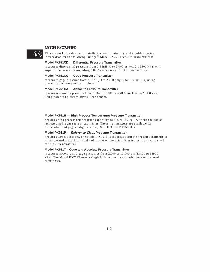
MODELS COVEREDThis manual provides basic installation, commissioning, and troubleshooting information for the following Omega® Model PX751 Pressure Transmitters:
Model PX751CD — Dif ferent ial Pressure Transmitt ermeasures differential pressure from 0.5 inH2O to 2,000 psi (0.12–13800 kPa) with superior performance including 0.075% accuracy and 100:1 rangeability.
Model PX751CG — Gage Pressur e Trans mitt ermeasures gage pressure from 2.5 inH2O to 2,000 psig (0.62–13800 kPa) using proven capacitance cell technology.
Model PX751CA — Ab solute Pressur e Transmitt ermeasures absolute pressure from 0.167 to 4,000 psia (8.6 mmHga to 27580 kPa) using patented piezoresistive silicon sensor.
Model PX751H — High Pro cess Temperatur e Pressure Transmitterprovides high process temperature capability to 375 °F (191°C), without the use of remote diaphragm seals or capillaries. These transmitters are available for differential and gage configurations (PX751HD and PX751HG).
Model PX751P — Reference Class Pressure Transmitterprovides 0.05% accuracy. The Model PX751P is the most accurate pressure transmitter available and is ideal for fiscal and allocation metering. Eliminates the need to stack multiple transmitters.
Model PX751T – Gage and Ab solu te Pressur e Transmitt ermeasures absolute and gage pressures from 2,000 to 10,000 psi (13800 to 68900 kPa). The Model PX751T uses a single isolator design and microprocessor-based electronics.
1-3
EN
USING THIS MANUALThis manual is designed to assist in basic installation and operation of Model PX751 Family of Smart Pressure Transmitters. For more detailed information, contact an Omega product specialist.
Section 2 Commissio ningprovides a description of common commissioning tasks.
Section 3 Instal lationprovides a flowchart outlining installation procedures and installation wiring diagrams.
Section 4 Trou bleshooti ngprovides basic troubleshooting techniques for common diagnostic messages associated with the transmitter and the communicator.
Section 5 Referenc e Dataprovides range tables, a typical model structure, and bolt torque specifications for Model PX751 Transmitters.
App endi cescontain menu trees and fast key sequences for the HART Communicator.
1-4
EN
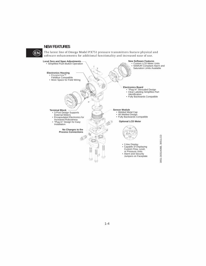
NEW FEATURESThe latest line of Omega Model PX751 pressure transmitters feature physical and software enhancements for additional functionality and increased ease of use.
Local Zero and Span Adjustments• Simplified Push-Button Operation
Termi nal Bl ock• 3-Post Design Supports
External Meters• Encapsulated Electronics for
Increased Robustness• “Plug-In” Design for Easy
Installation
Electron ics Bo ard• “Plug-In” Shrouded Design • Clear Labeling Simplifies Part
Identification• Fully Backwards Compatible
New Software Features• Custom LCD Meter Units• NAMUR Compliant Alarm and
Saturation Limits Available
Sensor Module• Welded Metal Cap• All Welded Design• Fully Backwards Compatible
No Changes to t heProcess Connect ions
Optional LCD M eter
• 2-line Display• Capable of Displaying
Custom Flow, Level, or Pressure Units
• Alarm and Security Jumpers on Faceplate
Electron ics Ho using• FOUNDATION™
Fieldbus Compatible• More Space for Field Wiring
3051
-303
1A08
B, 3
051L
CD

SECTION
2-1
EN2Commissioning
OVERVIEWThis section summarizes Model PX751 Transmitter commissioning procedures.
SAFETY MESSAGESProcedures and instructions in this section may require special precautions to ensure the safety of the personnel performing the operations. Information that raises potential safety issues is indicated by a warning symbol ( ). Refer to the following safety messages before performing an operation preceded by this symbol.
Warnings ( )
Explos ions can result in death or ser ious i njur y.
• Do not remove the transmitter covers in explosive environments when thecircuit is alive.
• Both transmitter covers must be fully engaged to meetexplosion-proof requirements.
• Before connecting a communicator in an explosive atmosphere, make sure the instruments in the loop are installed in accordance with intrinsically safe or nonincendive field wiring practices.
Electr ical sh ock can result in death or ser ious injur y.
• Avoid contact with the leads and the terminals. High voltage that may be present on leads can cause electrical shock.
2-2
EN
SETTING THE LOOP TO MANUALWhenever you are preparing to send or request data that would disrupt the loop or change the output of the transmitter, you will have to set your process application loop to manual. The HART Communicator Model HC275 will prompt you to set the loop to manual when necessary. Keep in mind that acknowledging this prompter does not set the loop to manual. It’s only a reminder; you have to set the loop to manual yourself, as a separate operation.
FAST KEY SEQUENCESFor your convenience, fast key sequences are listed for common transmitter functions. Complete tables of fast key sequences are located in Appendix A/ If you are unfamiliar with the communicator or how to follow fast key sequences, please refer to Appendix A for communicator operations.
The fast key boxes in this section contain codes for the HART Communicator Model HC275. From the Online menu (HART Communicator) press these key sequences to access the desired transmitter function.
CONFIGURE THE ANALOG OUTPUT PARAMETERS
NOTEThe position of the transmitter security jumper may prevent configuration changes. Refer to Section 5 for the proper placement of the transmitter security jumper.
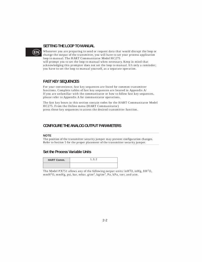
Set the Process Variable Units
The Model PX751 allows any of the following output units: inH2O, inHg, ftH2O, mmH2O, mmHg, psi, bar, mbar, g/cm2, kg/cm2, Pa, kPa, torr, and atm.
HART Comm. 1, 3, 2
2-3
EN
Set the Output Type
You can set the transmitter output to either linear or square root. Activate the transmitter square root output mode to make the analog output proportional to flow. While in square root output mode, the Model PX751 switches to linear output at 0.8% of ranged pressure input, or 9% of full scale flow output to avoid the extremely high gain that results as the input approaches zero. The transition from linear to square root output is smooth, with no step change or discontinuity in output.
Rerange The Range Values command sets the 4 and 20 mA points (lower and upper range values). Setting the range values to the limits of expected readings maximizes transmitter performance; the transmitter is most accurate when operated within the expected pressure ranges for your application. In practice, you may reset the transmitter range values as often as necessary to reflect changing process conditions.
NOTERegardless of the range points, the Model PX751 will measure and report all readings within the digital limits of the sensor. For example, if the 4 and 20 mA points are set to 0 and 10 inH20, and the transmitter detects a pressure of 25 inH20, it digitally outputs the 25 in H20 reading and a 250% percent of span reading. However, there may be up to ±5.0% error associated with output outside of the range points.
You may use one of three methods to rerange the transmitter. Each method is unique; examine all three closely before deciding which method to use.
HART Comm. 1, 3, 5
2-4
EN
Rerange with a Communicator Only
Reranging using only the communicator is the easiest and most popular way to rerange the transmitter. This method changes the values of the analog 4 and 20 mA points independently without a pressure input.
NOTEChanging the lower or upper range point results in similar changes to the span.
NOTEIf the transmitter security jumper is in the “ON” position, you will not be able to make adjustments to the zero and span. Refer to Figure 3-12 on Page 3-11 for the appropriate placement of the transmitter security jumper.
Rerange with a Pressure Input Source and a Communicator
Reranging using the communicator and a pressure source or process pressure is a way of reranging the transmitter when specific 4 and 20 mA points are not known. This method changes the values of the analog 4 and 20 mA points.
To rerange using the communicator and a pressure source or process pressure enter the fast-key sequence above, select 2 Apply values, and follow the on-line instructions.
NOTEIf the transmitter security jumper is in the “ON” position, you will not be able to make adjustments to the zero and span. Refer to Figure 3-12 on Page 3-11 for the appropriate placement of the transmitter security jumper.
HART Comm. 4 -or- 5
HART Comm. 1, 2, 3, 1, 2
2-5
EN
Rerange with a Pressure Input Source and the Local Zero and Span ButtonsReranging using the local zero and span adjustments (see Figure 2-1), and a pressure source is a way of reranging the transmitter when specific 4 and 20 mA points are not known and a communicator is not available.
NOTEWhen you set the 4 mA point the span is maintained; when you set the 20 mA point the span changes. If you set the lower range point to a value that causes the upper range point to exceed the sensor limit, the upper range point is automatically set to the sensor limit, and the span is adjusted accordingly.
To rerange the transmitter using the span and zero buttons, perform the following procedure.
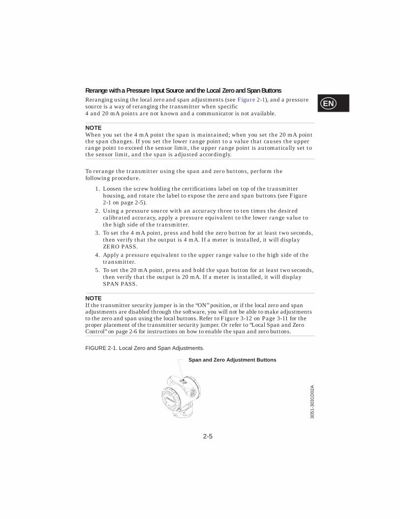
1. Loosen the screw holding the certifications label on top of the transmitter housing, and rotate the label to expose the zero and span buttons (see Figure 2-1 on page 2-5).
2. Using a pressure source with an accuracy three to ten times the desired calibrated accuracy, apply a pressure equivalent to the lower range value to the high side of the transmitter.
3. To set the 4 mA point, press and hold the zero button for at least two seconds, then verify that the output is 4 mA. If a meter is installed, it will display ZERO PASS.
4. Apply a pressure equivalent to the upper range value to the high side of the transmitter.
5. To set the 20 mA point, press and hold the span button for at least two seconds, then verify that the output is 20 mA. If a meter is installed, it will display SPAN PASS.
NOTEIf the transmitter security jumper is in the “ON” position, or if the local zero and span adjustments are disabled through the software, you will not be able to make adjustments to the zero and span using the local buttons. Refer to Figure 3-12 on Page 3-11 for the proper placement of the transmitter security jumper. Or refer to “Local Span and Zero Control” on page 2-6 for instructions on how to enable the span and zero buttons.
FIGURE 2-1. Local Zero and Span Adjustments.
Span and Zero Adjustment Buttons
3051
-303
1D02
A
2-6
EN
Local Span and Zero Control
The Local keys command allows software control over the use of the local span and zero adjustments. To enable or disable the span and zero adjustment buttons on your transmitter, perform the fast key sequence above.
NOTEDisabling the local keys only disables transmitter configuration changes using the zero and span buttons. With the local keys disabled, you can still make changes to the transmitter configuration using a Hart Communicator.
Set the Damping
The Model PX751 electronic damping feature changes the response time of the transmitter to smooth variations in output readings caused by rapid changes in input. Determine the appropriate damping setting based on the necessary response time, signal stability, and other requirements of the loop dynamics of your system.
LCD Meter Options
The Meter Options command allows you to customize the LCD meter for use in your application. You can configure the meter to display the following information:
n Engineering Unitsn Percent of Rangen User-Configurable LCD Scale(1)
n Alternating between any two of the aboveThe user-configurable scale (2 CM Setup) is a new feature that enables you to configure the LCD meter to a custom scale using a Model HC275 HART communicator. With this feature you can define the decimal point position, the upper range value, the lower range value, the engineering units, and the transfer function. For more detailed LCD meter information, contact an Omega product specialist. .
(1) The user-configurable LCD scale is a feature specific to the new 4–20 mA output transmitters. It is not available with Low Power transmitters.
HART Comm. 1, 4, 4, 1, 7
HART Comm. 1, 3, 6
HART Comm. 1, 4, 3, 4
2-7
EN
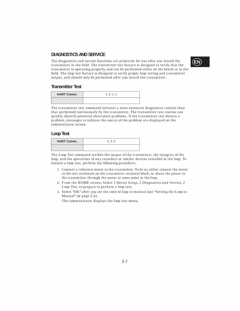
DIAGNOSTICS AND SERVICE The diagnostics and service functions are primarily for use after you install the transmitter in the field. The transmitter test feature is designed to verify that the transmitter is operating properly, and can be performed either on the bench or in the field. The loop test feature is designed to verify proper loop wiring and transmitter output, and should only be performed after you install the transmitter.
Transmitter Test
The transmitter test command initiates a more extensive diagnostics routine than that performed continuously by the transmitter. The transmitter test routine can quickly identify potential electronics problems. If the transmitter test detects a problem, messages to indicate the source of the problem are displayed on the communicator screen.
Loop Test
The Loop Test command verifies the output of the transmitter, the integrity of the loop, and the operations of any recorders or similar devices installed in the loop. To initiate a loop test, perform the following procedure:
1. Connect a reference meter to the transmitter. To do so, either connect the meter to the test terminals on the transmitter terminal block, or shunt the power to the transmitter through the meter at some point in the loop.
2. From the HOME screen, Select 1 Device Setup, 2 Diagnostics and Service, 2 Loop Test, to prepare to perform a loop test.
3. Select “OK” after you set the control loop to manual (see “Setting the Loop to Manual” on page 2-2).The communicator displays the loop test menu.
HART Comm. 1, 2, 1, 1
HART Comm. 1, 2, 2
2-8
EN
4. Select a discreet milliamp level for the transmitter to output. At the “Choose analog output” prompt, select 1 4mA, 2 20mA, or select 3 other to manually input a value. If you are performing a loop test to verify the output of a transmitter, enter a value between 4 and 20 mA. If you are performing a loop test to verify the transmitter alarm levels, enter the milliamp value at which the transmitter should enter an alarm state (see Table 3-1 on page 3-12).
5. Check the electrical current meter installed in the test loop to verify that it reads the value you commanded the transmitter to output. If the readings match, the transmitter and the loop are configured and functioning properly. If the readings do not match, there may be a fault in the wiring, the transmitter may require an output trim, or the electrical current meter may be malfunctioning.
After completing the test procedure, the display returns to the loop test screen and allows you to choose another output value or to exit loop testing.
CALIBRATIONCalibrating a smart transmitter is different from calibrating an analog transmitter. The one-step calibration process of an analog transmitter is done in three steps with a smart transmitter:
n Rerange – sets the 4 and 20 mA points at the desired pressures;n Sensor Trim – Adjusts the factory characterization curve to optimize the
transmitter performance over a specified pressure range or to adjust for mounting effects;
n Analog Output Trim – Adjusts the analog output to match the plant standard or the control loop.
2-9
EN
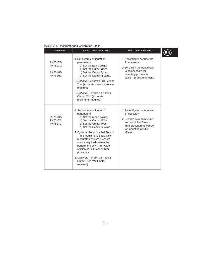
TABLE 2-1. Recommended Calibration Tasks.
Transmi tter Bench Cali brat ion Tasks Field Cali bration Tasks
PX751CDPX751CG
PX751HDPX751HG
1.Set output configuration parameters:
a) Set the range points. b) Set the Output Units. c) Set the Output Type. d) Set the Damping Value.
2.Optional: Perform a Full Sensor Trim (Accurate pressure source required)
3.Optional: Perform an Analog Output Trim (Accurate multimeter required)
1.Reconfigure parameters if necessary.
2.Zero Trim the transmitter to compensate for mounting position or static pressure effects.
PX751CAPX751TAPX751TG
1.Set output configuration parameters:
a) Set the range points. b) Set the Output Units. c) Set the Output Type. d) Set the Damping Value.
2.Optional: Perform a Full Sensor Trim if equipment is available (accurate absolute pressure source required), otherwiseperform the Low Trim Value section of Full Sensor Trim procedure.
3.Optional: Perform an Analog Output Trim (Multimeter required)
1.Reconfigure parameters if necessary.
2.Perform Low Trim Value section of Full Sensor Trim procedure to correct for mounting position effects.
2-10
EN
Calibration OverviewComplete calibration of the Model PX751 Pressure Transmitter involves the following tasks:
Confi gure t he Analog Ou tput P arametersn Set Process Variable Units (Page 2-2)n Set Output Type (Page 2-3)n Rerange (Page 2-3)n Set Damping (Page 2-6)
Calibrate the Sensorn Full Trim (Page 2-14)n Zero Trim (Page 2-13)
Calibrate the 4–20 mA Out putn 4–20 mA Output Trim (Page 2-14) orn 4–20 mA Output Trim Using Other Scale (Page 2-16) or
Deciding Which Trim Procedure to UseTo decide which trim procedure to use, you must first determine whether the analog-to-digital section or the digital-to-analog section of the transmitter electronics is in need of calibration. To do so, perform the following procedure:
1. Connect a pressure source, a HART communicator, and a digital readout device to the transmitter.
2. Establish communication between the transmitter and the communicator.
3. Apply pressure equal to the upper range point pressure (100 in H20, for example).
4. Compare the applied pressure to the Process Variable (PV) line on the Communicator Online Menu. If the PV reading on the communicator does not match the applied pressure, and you are confident that your test equipment is accurate, perform a sensor trim.
5. Compare the Analog Output (AO) line on the communicator online menu to the digital readout device. If the AO reading on the communicator does not match the digital readout device, and you are confident that your test equipment is accurate, perform an output trim.
2-11
EN
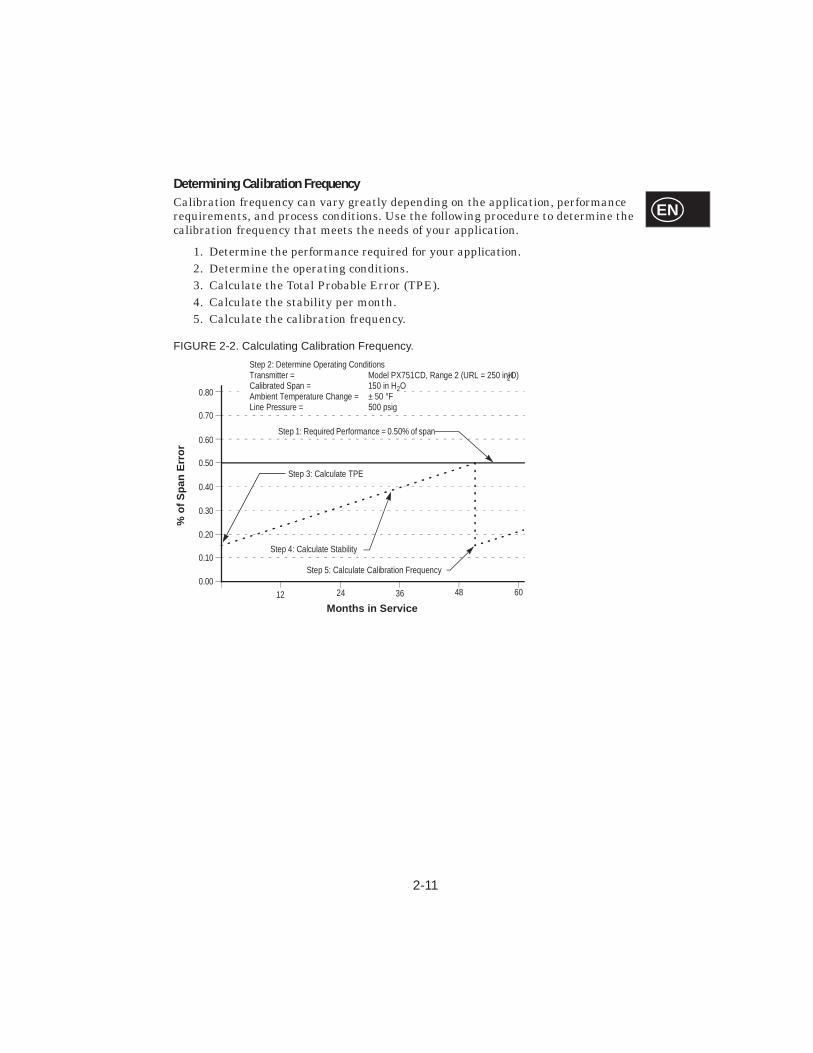
Determining Calibration FrequencyCalibration frequency can vary greatly depending on the application, performance requirements, and process conditions. Use the following procedure to determine the calibration frequency that meets the needs of your application.
1. Determine the performance required for your application.2. Determine the operating conditions.3. Calculate the Total Probable Error (TPE).4. Calculate the stability per month.5. Calculate the calibration frequency.
FIGURE 2-2. Calculating Calibration Frequency.
0.00
0.10
0.20
0.30
0.40
0.50
0.60
0.70
0.80
12 24 36 48 60
Months in Service
% o
f S
pan
Err
or
Step 1: Required Performance = 0.50% of span
Step 2: Determine Operating ConditionsTransmitter = Model PX751CD, Range 2 (URL = 250 inH2O)Calibrated Span = 150 in H2OAmbient Temperature Change = ± 50 °FLine Pressure = 500 psig
Step 3: Calculate TPE
Step 5: Calculate Calibration Frequency
Step 4: Calculate Stability
2-12
EN
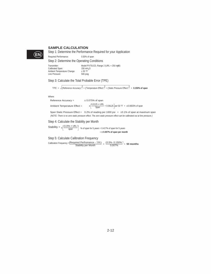
SAMPLE CALCUL ATIONStep 1: Determine the Performance Required for your ApplicationRequired Performance: 0.50% of span
Step 2: Determine the Operating ConditionsTransmitter: Model PX751CD, Range 2 (URL = 250 inH2O)Calibrated Span: 150 inH2OAmbient Temperature Change: ± 50 °FLine Pressure: 500 psig
Step 3: Calculate the Total Probable Error (TPE)
Where:
Reference Accuracy = ± 0.075% of span
Ambient Temperature Effect =
Span Static Pressure Effect = 0.2% of reading per 1000 psi = ±0.1% of span at maximum span
Step 4: Calculate the Stability per Month
Stability =
Step 5: Calculate Calibration FrequencyCalibration Frequency =
TPE Reference Accuracy( )2Temperature Effect( )2
Static Pressure Effect( )2+ + 0.150% of span = =
0.0125 URL×Span
-------------------------------------- 0.06125+ per 50 °F± 0.0833% of span±=
0.25% URL×( )span------------------------------------------± % of span for 5 years = 0.417% of span for 5 years
= ± 0.007% of span per month
(Required Perfromance TPE)–Stability per Month---------------------------------------------------------------------------------
0.5%- 0.150%( )0.007%------------------------------------------ 50 months= =
(NOTE: There is no zero static pressure effect. The zero static pressure effect can be calibrated out at line pressure.)
2-13
EN
Sensor TrimYou can trim the sensor using either the full trim or the zero trim function. The trim functions vary in complexity, and their use is application-dependent. Both trim functions alter the transmitter’s interpretation of the input signal.
NOTETrimming the sensor adjusts the position of the factory characterization curve. It is possible to degrade the performance of the transmitter if the sensor trim is done improperly or with equipment that does not meet the accuracy requirements.
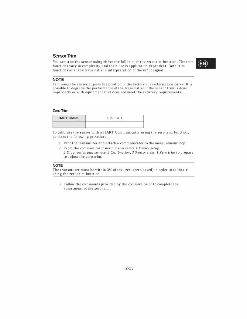
Zero Trim
To calibrate the sensor with a HART Communicator using the zero trim function, perform the following procedure.
1. Vent the transmitter and attach a communicator to the measurement loop.2. From the communicator main menu select 1 Device setup,
2 Diagnostics and service, 3 Calibration, 3 Sensor trim, 1 Zero trim to prepare to adjust the zero trim.
NOTEThe transmitter must be within 3% of true zero (zero based) in order to calibrate using the zero trim function.
3. Follow the commands provided by the communicator to complete the adjustment of the zero trim.
HART Comm. 1, 2, 3, 3, 1
2-14
EN
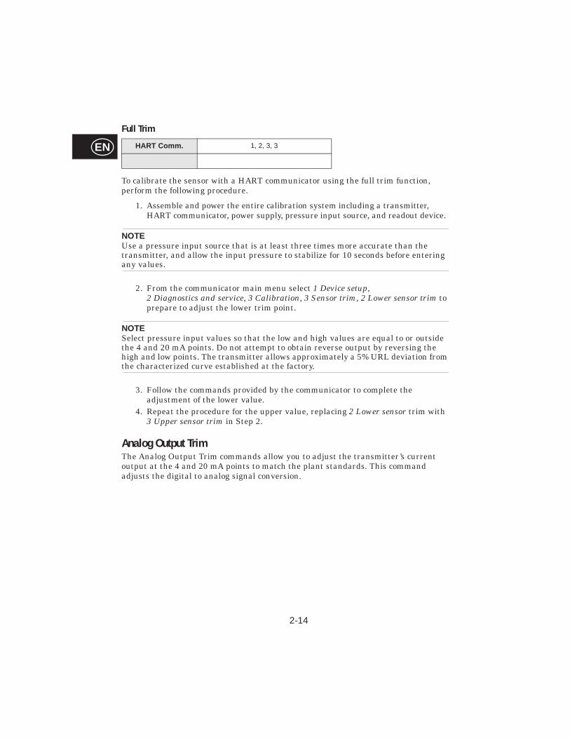
Full Trim
To calibrate the sensor with a HART communicator using the full trim function, perform the following procedure.
1. Assemble and power the entire calibration system including a transmitter, HART communicator, power supply, pressure input source, and readout device.
NOTEUse a pressure input source that is at least three times more accurate than the transmitter, and allow the input pressure to stabilize for 10 seconds before entering any values.
2. From the communicator main menu select 1 Device setup,2 Diagnostics and service, 3 Calibration, 3 Sensor trim, 2 Lower sensor trim to prepare to adjust the lower trim point.
NOTESelect pressure input values so that the low and high values are equal to or outside the 4 and 20 mA points. Do not attempt to obtain reverse output by reversing the high and low points. The transmitter allows approximately a 5% URL deviation from the characterized curve established at the factory.
3. Follow the commands provided by the communicator to complete the adjustment of the lower value.
4. Repeat the procedure for the upper value, replacing 2 Lower sensor trim with 3 Upper sensor trim in Step 2.
Analog Output TrimThe Analog Output Trim commands allow you to adjust the transmitter’s current output at the 4 and 20 mA points to match the plant standards. This command adjusts the digital to analog signal conversion.
HART Comm. 1, 2, 3, 3
2-15
EN
Digital to Analog Trim
To perform a digital-to-analog trim with a HART communicator, perform the following procedure.
1. From the HOME screen, select 1 Device setup, 2 Diag/Service, 3 Calibration, 4 D/A trim. Select “OK” after you set the control loop to manual (see “Setting the Loop to Manual” on page 2-2).
2. Connect an accurate reference ammeter to the transmitter at the “Connect reference meter” prompt. To do so, connect the positive lead to the positive terminal and the negative lead to the test terminal in the transmitter terminal compartment, or shunt the transmitter power through the reference meter at some point.
3. Select “OK” after connecting the reference meter.4. Select “OK” at the “Setting fld dev output to 4 mA” prompt.
The transmitter outputs 4.00 mA. 5. Record the actual value from the reference meter, and enter it at the “Enter
meter value” prompt. The communicator prompts you to verify whether or not the output value equals the value on the reference meter.
6. Select 1 Yes if the reference meter value equals the transmitter output value, or 2 No if it does not. If you select 1 Yes, proceed to Step 7.If you select 2 No, repeat Step 5.
7. Select “OK” at the “Setting fld dev output to 20 mA” prompt, and repeat Steps 5 and 6 until the reference meter value equals the transmitter output value.
8. Select “OK” after you return the control loop to automatic control.
HART Comm. 1, 2, 3, 2, 1
2-16
EN
Digital to Analog Trim Using Other Scale
The Scaled D/A Trim command matches the 4 and 20 mA points to a user-selectable reference scale other than 4 and 20 mA (1 to 5 volts if measuring across a 250 ohm load, or 0 to 100 percent if measuring from a DCS, for example). To perform a scaled D/A trim, connect an accurate reference meter to the transmitter and trim the output signal to scale as outlined in the Output Trim procedure.
NOTEUse a precision resistor for optimum accuracy. If you add a resistor to the loop, ensure that the power supply is sufficient to power the transmitter to a 20 mA output with the additional loop resistance.
Compensating Model PX751 Range 4 and 5Differential Pressure Transmitters for Line PressureModel PX751 Range 4 and Range 5 pressure transmitters require a special calibration procedure when used in differential pressure applications. The purpose of this procedure is to optimize transmitter performance by reducing the effect of static line pressure in these applications. Model PX751 differential pressure transmitters (Ranges 1, 2, and 3) do not require this procedure because the optimization occurs in the sensor.
Applying high static pressure to Model PX751 Range 4 and Range 5 pressure transmitters causes a systematic shift in the output. This shift is linear with static pressure; correct it by performing the Full Trim procedure on page 2-14.
The following specifications show the static pressure effect for Model PX751 Range 4 and Range 5 transmitters used in differential pressure applications:
Zero Effect: ±0.1% of the upper range limit per 1,000 psi (6.9 MPa) for line pressures from 0 to 2,000 psi (0 to 13.8 MPa).±0.2% of the upper range limit per 1,000 psi (6.9 MPa) for line pressures above 2,000 psi (13.8 MPa).
Span Effect: Correctable to ±0.2% of reading per 1,000 psi for line pressures from 0 to 3,626 psi.
The systematic span shift caused by the application of static line pressure is –1.00% of reading per 1,000 psi for PX751C Range 4 transmitters,and –1.25% of reading per 1,000 psi for Range 5 transmitters.
Use the following example to compute corrected input values.
HART Comm. 1, 2, 3, 2, 2
2-17
EN
ExampleA transmitter with model number PX751CD-4 will be used in a differential pressure application where the static line pressure is 1,200 psi. The transmitter is ranged so that the output is 4 mA at 500 inH2O and 20 mA at 1,500 inH2O.
To correct for systematic error caused by high static line pressure, first use the following formulas to determine corrected values for the low trim and high trim.
LT = LRV + S (LRV) P
Where: LT = Corrected Low Trim Value
LRV = Lower Range ValueS = –(Span shift per specification)
P = Static Line PressureHT = URV + S (URV) P
Where: HT = Corrected High Trim Value
URV = Upper Range ValueS = –(Span shift per specification)
P = Static Line Pressure
In this example:
URV = 1,500 inH2O
LRV = 500 inH2OP = 1,200 psiS = +0.01/1000
To calculate the low trim (LT) value:
LT = 500 + (0.01/1000)(500)(1200)LT = 506 inH2O
To calculate the high trim (HT) value:
HT= 1500 + (0.01/1000)(1500)(1200)
HT= 1,518 inH2OTo complete a Model PX751 full trim and enter the corrected values for low trim (LT) and high trim (HT) (see “Full Trim” on page 2-14).
Enter the corrected input values for low trim and high trim through the communicator keypad after you apply the nominal value of pressure as the transmitter input.
NOTEAfter calibrating Model PX751 Range 4 and Range 5 transmitters for high differential pressure applications, rerange the 4 and 20 mA points using the communicator to maintain the systematic static line pressure correction. You may re-zero the 4 mA point after installation using the local zero button without affecting the completed calibration.

2-18
EN
SECTION
3-1
EN3Installation
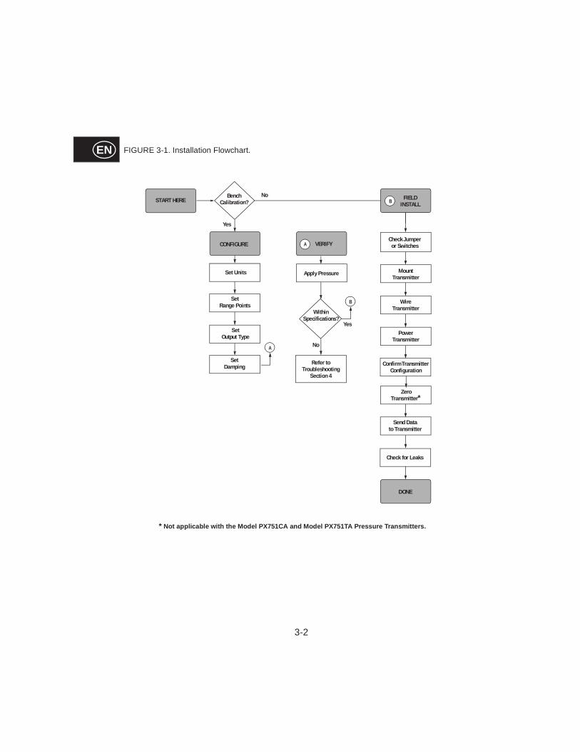
OVERVIEWThis section contains safety messages, an installation flowchart (see Figure 3-1 on Page 3-2), and basic mechanical and electrical considerations to guide you through a successful Model PX751 installation. For more detailed information, contact Omega.
SAFETY MESSAGESProcedures and instructions in this section may require special precautions to ensure the safety of the personnel performing the operations. Information that raises potential safety issues is indicated by a warning symbol ( ). Refer to the following safety messages before performing an operation preceded by this symbol.
Warnings ( )
Explos ions can result in death or ser ious i njur y.
• Do not remove the transmitter covers in explosive environments when thecircuit is alive.
• Both transmitter covers must be fully engaged to meetexplosion-proof requirements.
• Before connecting a communicator in an explosive atmosphere, make sure the instruments in the loop are installed in accordance with intrinsically safe or nonincendive field wiring practices.
Electr ical sh ock can result in death or ser ious injur y.
• Avoid contact with the leads and the terminals. High voltage that may be present on leads can cause electrical shock.
3-2
EN FIGURE 3-1. Installation Flowchart.
B
Check Jumper or Switches
Wire Transmitter
PowerTransmitter
ZeroTransmitter*
DONE
MountTransmitter
START HERE FIELD INSTALL
A
Yes
No
Apply Pressure
Refer toTroubleshooting
Section 4
Within Specifications?
VERIFY
B
CONFIGURE
Set Units
Set Range Points
Set Output Type
Set Damping
NoBenchCalibration?
Yes
A
Check for Leaks
* Not applic able with t he Model PX751CA and Model PX751TA Pres sure Transmi tters.
Confirm Transmitter Configuration
Send Data to Transmitter
3-3
EN
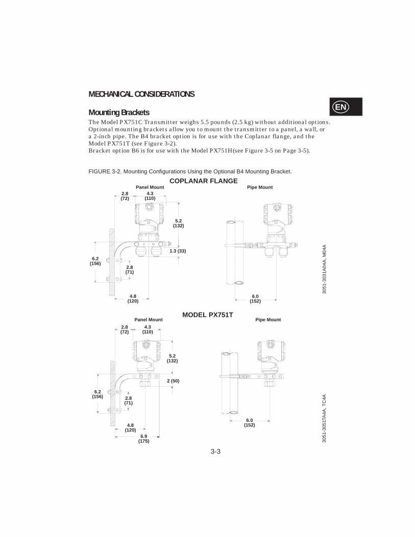
MECHANICAL CONSIDERATIONS
Mounting Brackets The Model PX751C Transmitter weighs 5.5 pounds (2.5 kg) without additional options. Optional mounting brackets allow you to mount the transmitter to a panel, a wall, or a 2-inch pipe. The B4 bracket option is for use with the Coplanar flange, and the Model PX751T (see Figure 3-2). Bracket option B6 is for use with the Model PX751H(see Figure 3-5 on Page 3-5).
FIGURE 3-2. Mounting Configurations Using the Optional B4 Mounting Bracket.
1.3 (33)
5.2(132)
4.8(120)
2.8(71)
2.8(72)
4.3(110)
6.2(156)
3051
-303
1A04
A, M
04A
6.0(152)
Panel Mount Pipe MountCOPLANAR FLANGE
2 (50)
5.2(132)
4.8(120)
2.8(71)
2.8(72)
4.3(110)
6.2(156)
6.0(152)
Panel Mount Pipe MountMODEL PX751T
6.9 (175) 30
51-3
051T
A4A
, TC
4A
3-5
EN
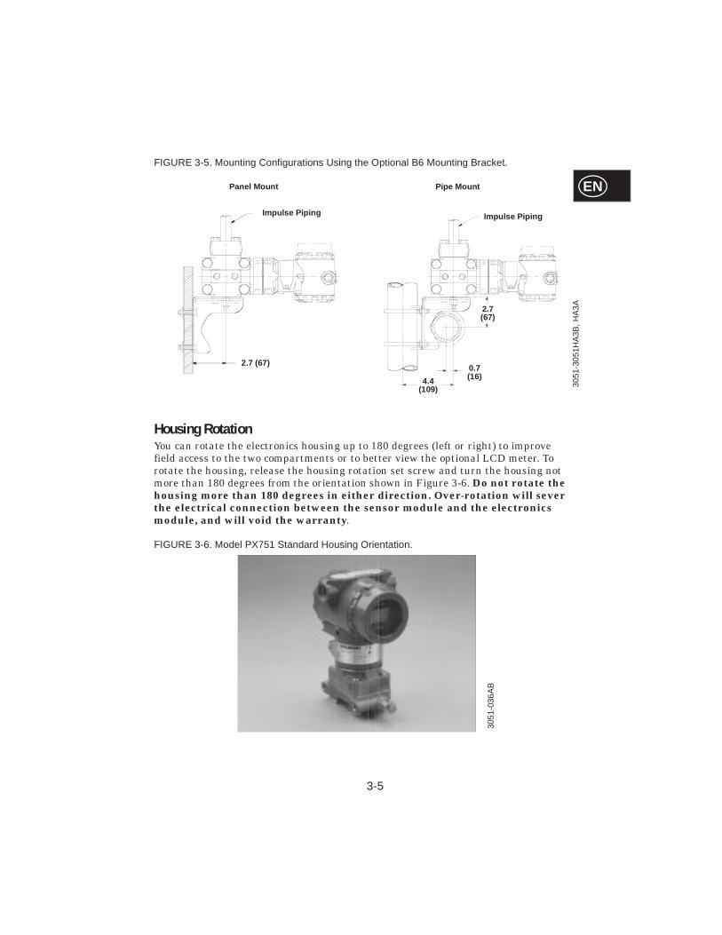
FIGURE 3-5. Mounting Configurations Using the Optional B6 Mounting Bracket.
Housing RotationYou can rotate the electronics housing up to 180 degrees (left or right) to improve field access to the two compartments or to better view the optional LCD meter. To rotate the housing, release the housing rotation set screw and turn the housing not more than 180 degrees from the orientation shown in Figure 3-6. Do not rotate the housing more than 180 degrees in either direction. Over-rotation will sever the electrical connection between the sensor module and the electronics module, and will void the warranty.
FIGURE 3-6. Model PX751 Standard Housing Orientation.
Impulse Piping
0.7(16)4.4
(109)
2.7 (67)
Impulse Piping
2.7 (67)
Panel Mount Pipe Mount
3051
-305
1HA
3B, H
A3A
3051
-036
AB
3-6
EN
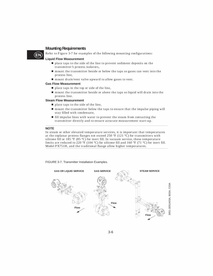
Mounting RequirementsRefer to Figure 3-7 for examples of the following mounting configurations:
Liq uid Flow Measurem entn place taps to the side of the line to prevent sediment deposits on the
transmitter’s process isolators,n mount the transmitter beside or below the taps so gases can vent into the
process line,n mount drain/vent valve upward to allow gases to vent.
Gas Flow Mea surement n place taps in the top or side of the line,n mount the transmitter beside or above the taps so liquid will drain into the
process line.Steam Flow Measurement
n place taps to the side of the line, n mount the transmitter below the taps to ensure that the impulse piping will
stay filled with condensate,n fill impulse lines with water to prevent the steam from contacting the
transmitter directly and to ensure accurate measurement start-up.
NOTE In steam or other elevated temperature services, it is important that temperatures at the coplanar process flanges not exceed 250 °F (121 °C) for transmitters with silicone fill or 185 °F (85 °C) for inert fill. In vacuum service, these temperature limits are reduced to 220 °F (104 °C) for silicone fill and 160 °F (71 °C) for inert fill. Model PX751H, and the traditional flange allow higher temperatures.
FIGURE 3-7. Transmitter Installation Examples.
GAS OR LIQUID SERVICE
Flow
GAS SERVICE STEAM SERVICE
Flow 3051
-305
1A03
A, B
03A
, C03
A
Flow

3-7
EN
ELECTRICAL CONSIDERATIONS
Power Supply4–20 mA TransmittersThe dc power supply should provide power with less than 2 percent ripple. The total resistance load is the sum of the resistance and signal leads and the load resistance of the controller, indicator, and related pieces. Note that the resistance of intrinsic safety barriers, if used, must be included. Refer to Figure 3-8 for power supply load limitations.
NOTEIf a single power supply is used to power more than one Model PX751 Transmitter, the power supply used and the circuitry common to the transmitters should not have more than 20 ohms of impedance at 1200 Hz.
NOTEA resistance of at least 250 ohms must exist between the communicator and the power supply for communications.
FIGURE 3-8. Power Supply Requirements.
Low Power TransmittersLow power transmitters require a 6–12 V dc external power supply.
Communication requires a minimum loop resis tance of 250 ohms.Minimum termi nal voltage for transmitter is 10.5 V wi th no load.
Load
(O
hms)
Operat ing Region
3051
-010
3A
(1) For CSA approval, power supply must not exceed 42.4 V.
Voltage (V dc)
Max. Loop Resistance = 43.5 3 (Power Supply Voltage – 10.5)
3-8
EN
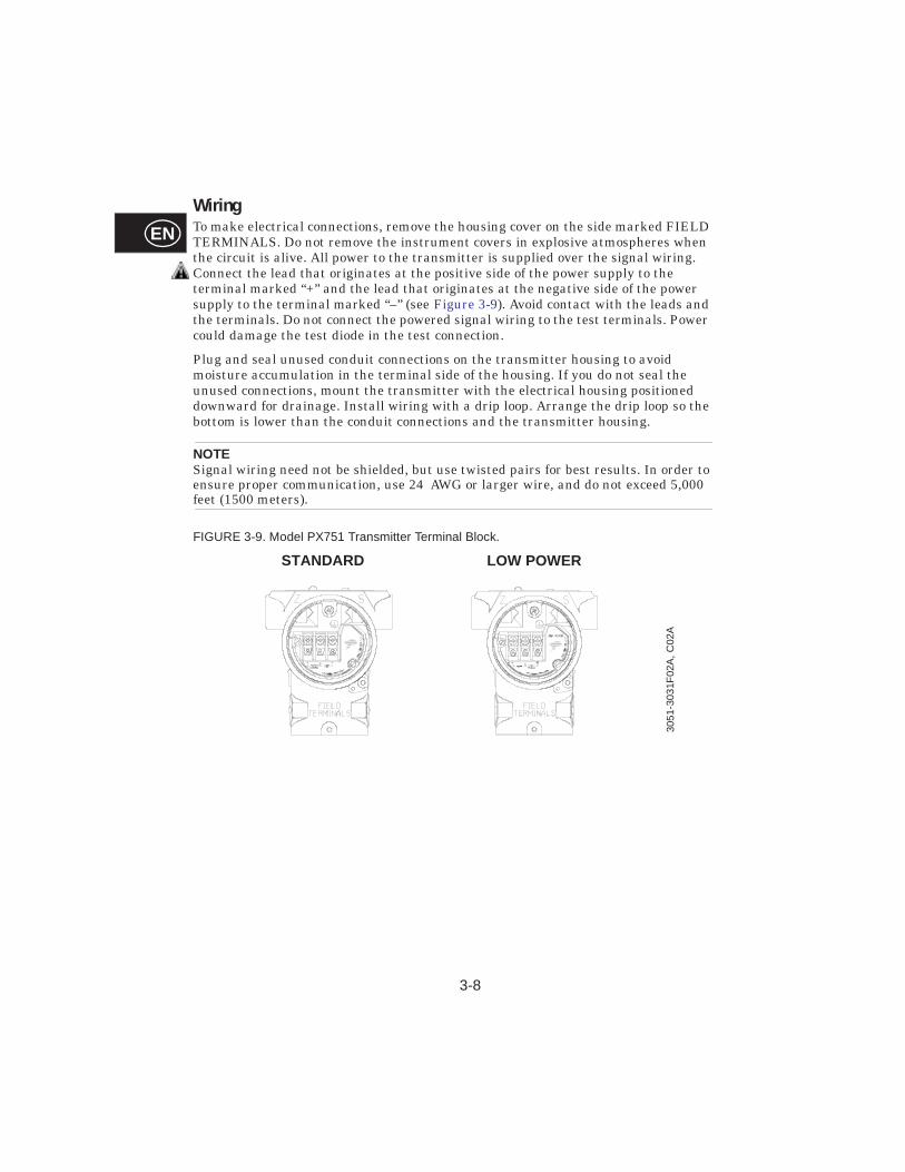
WiringTo make electrical connections, remove the housing cover on the side marked FIELD TERMINALS. Do not remove the instrument covers in explosive atmospheres when the circuit is alive. All power to the transmitter is supplied over the signal wiring. Connect the lead that originates at the positive side of the power supply to the terminal marked “+” and the lead that originates at the negative side of the power supply to the terminal marked “–” (see Figure 3-9). Avoid contact with the leads and the terminals. Do not connect the powered signal wiring to the test terminals. Power could damage the test diode in the test connection.
Plug and seal unused conduit connections on the transmitter housing to avoid moisture accumulation in the terminal side of the housing. If you do not seal the unused connections, mount the transmitter with the electrical housing positioned downward for drainage. Install wiring with a drip loop. Arrange the drip loop so the bottom is lower than the conduit connections and the transmitter housing.
NOTESignal wiring need not be shielded, but use twisted pairs for best results. In order to ensure proper communication, use 24 AWG or larger wire, and do not exceed 5,000 feet (1500 meters).
FIGURE 3-9. Model PX751 Transmitter Terminal Block.
STANDARD LOW POWER
3051
-303
1F02
A, C
02A
3-9
EN
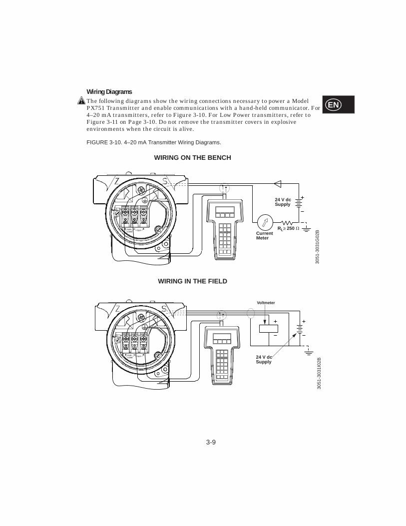
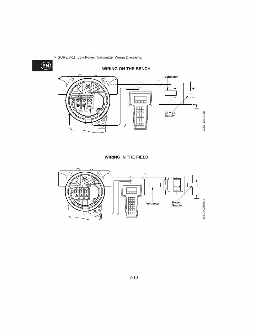
Wiring DiagramsThe following diagrams show the wiring connections necessary to power a Model PX751 Transmitter and enable communications with a hand-held communicator. For 4–20 mA transmitters, refer to Figure 3-10. For Low Power transmitters, refer to Figure 3-11 on Page 3-10. Do not remove the transmitter covers in explosive environments when the circuit is alive.
FIGURE 3-10. 4–20 mA Transmitter Wiring Diagrams.
3051
-303
1G02
BCurrent Meter
24 V dc Supply
RL≥ 250 V
3051
-303
1I02
B
Vol tmeter
24 V dc Supply
WIRING ON THE BENCH
WIRING IN THE FIELD
3-10
EN
FIGURE 3-11. Low Power Transmitter Wiring Diagrams.
Power Supply
3051
-303
1I02
B30
51-3
031E
02B
Voltmeter
WIRING ON THE BENCH
WIRING IN THE FIELD
Voltmeter
24 V dc Supply
3-11
EN
FAILURE MODE ALARMAs part of normal operation, the Model PX751 continuously monitors its own operation. This automatic diagnostic routine is a timed series of checks repeated continuously. If the diagnostic routine detects a failure, the transmitter drives its output either below or above specific values depending on the position of the failure mode jumper.
n For 4–20 mA transmitters factory-configured for standard operation, the transmitter drives its output either below 3.75 mA or above 21.75 mA.
n For 4–20 mA transmitters factory-configured for NAMUR-compliant operation, the transmitter drives its output either below 3.6 mA or above 22.5 mA.
n For low-power transmitters configured for 1–5 Volts, the transmitter drives its output either below 0.95 V or above 5.4 V.
n For low-power transmitters configured for 0.8–3.2 Volts, the transmitter drives its output either below 0.75 V or above 4.2 V.
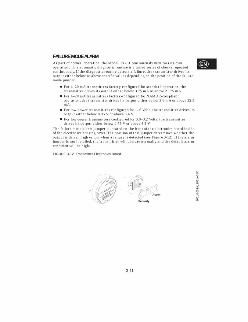
The failure mode alarm jumper is located on the front of the electronics board inside of the electronics housing cover. The position of this jumper determines whether the output is driven high or low when a failure is detected (see Figure 3-12). If the alarm jumper is not installed, the transmitter will operate normally and the default alarm condition will be high.
FIGURE 3-12. Transmitter Electronics Board.
Alarm
Security
OFFON LO
HI
3051
-305
1A, 3
031A
05C
3-12
EN
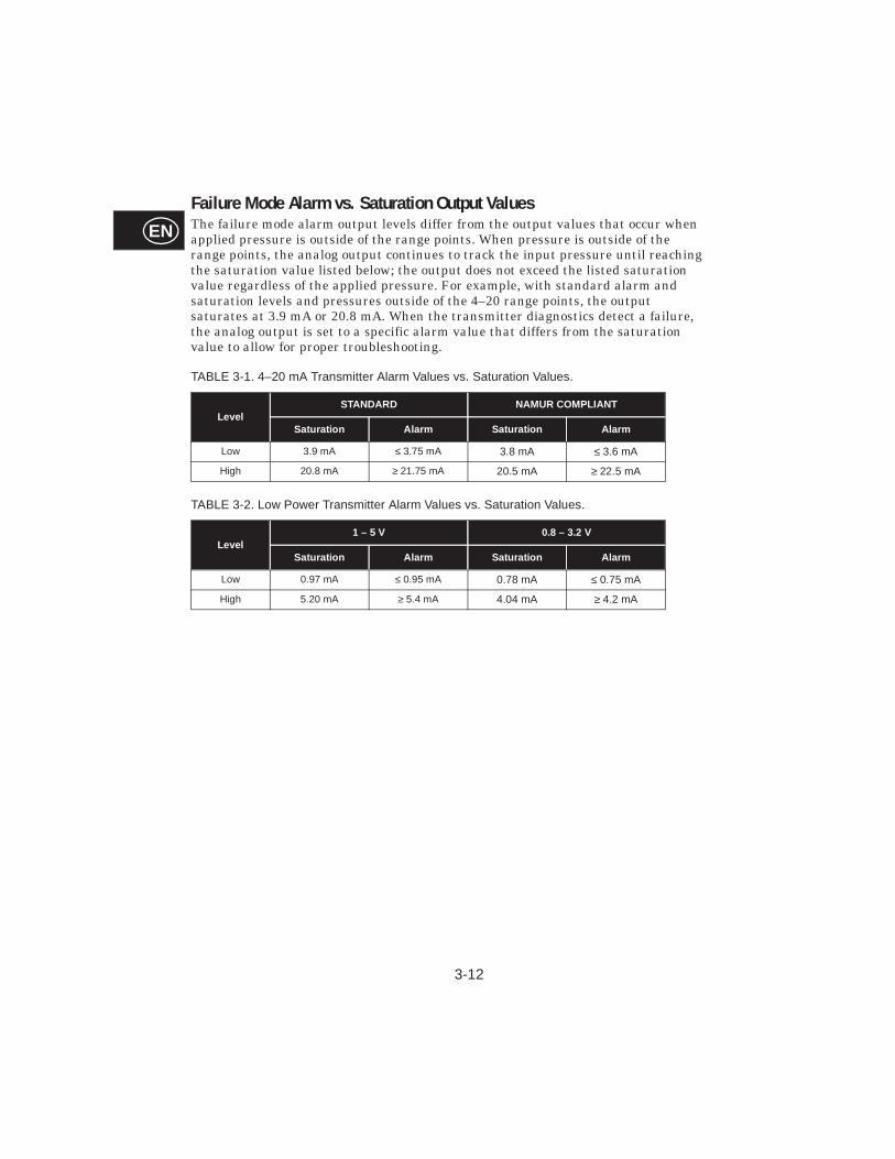
Failure Mode Alarm vs. Saturation Output ValuesThe failure mode alarm output levels differ from the output values that occur when applied pressure is outside of the range points. When pressure is outside of the range points, the analog output continues to track the input pressure until reaching the saturation value listed below; the output does not exceed the listed saturation value regardless of the applied pressure. For example, with standard alarm and saturation levels and pressures outside of the 4–20 range points, the output saturates at 3.9 mA or 20.8 mA. When the transmitter diagnostics detect a failure, the analog output is set to a specific alarm value that differs from the saturation value to allow for proper troubleshooting.
TABLE 3-1. 4–20 mA Transmitter Alarm Values vs. Saturation Values.
TABLE 3-2. Low Power Transmitter Alarm Values vs. Saturation Values.
LevelSTANDARD NAMUR COMPLIANT
Saturation Alarm Saturation Alarm
Low 3.9 mA ≤ 3.75 mA 3.8 mA ≤ 3.6 mA
High 20.8 mA ≥ 21.75 mA 20.5 mA ≥ 22.5 mA
Level1 – 5 V 0.8 – 3.2 V
Saturation Alarm Saturation Alarm
Low 0.97 mA ≤ 0.95 mA 0.78 mA ≤ 0.75 mA
High 5.20 mA ≥ 5.4 mA 4.04 mA ≥ 4.2 mA
SECTION
4-1
EN4Troubleshooting
OVERVIEWTable 4-1 provides summarized troubleshooting suggestions for the most common operating problems.
Failure to follow safe operating practices can cause death or serious injury. Please review the following safety messages before troubleshooting the Model PX751 Pressure Transmitter.
n Using improper procedures or parts can affect product performance and the output signal used to control a process. To ensure safe transmitter performance, use only new parts and follow Omega documented procedures. Questions regarding these procedures or parts should be directed to Omega's customer service dept.
n Isolate a failed transmitter from its pressure source as soon as possible. Pressure that may be present could cause death or serious injury to personnel if the transmitter is disassembled or ruptures under pressure.
n To avoid explosions, do not remove the instrument cover or make electrical connections in explosive atmospheres when the circuit is alive. Make sure the instrument is installed in accordance with intrinsically safe or nonincendive field wiring practice.
n To meet explosion proof requirements, make sure that both transmitter covers are fully engaged.
n To avoid process leaks, use only the O-ring designed to seal with the corresponding flange adapter. Omega supplies two unique styles of O-rings for Omega flange adapters: one for Model PX751 flange adapters and another for Model PX750 flange adapters. Each flange adapter is distinguished by its unique groove. Refer to the Spare Parts List PPL 4001 for the numbers of the flange adapters and O-rings designed for the Model PX751 Pressure Transmitter.

4-2
EN Troubleshooting
TABLE 4-1. Model PX751 Troubleshooting Chart.
Symptom Correct ive Ac tions
Milliamp Reading is Zero • Check if Power Polarity is Reversed• Verify Voltage Across Terminals (should be 10 to 55 V dc)• Check for Bad Diode in Terminal Block• Replace Transmitter Terminal Block
Transmitter is not Communicating with Communicator
• Check Power Supply Voltage at Transmitter (Minimum 10.5 V)• Check Load Resistance (250 V minimum)• Check if Unit is Addressed Properly• Replace Electronics Board
Milliamp Reading is Low or High • Check Pressure Variable Reading for Saturation• Check if Output is in Alarm Condition• Perform 4–20 mA Output Trim• Replace Electronics Board
No Response toChanges in Applied Pressure
• Check Test Equipment• Check Impulse Piping for Blockage• Check for Disabled Span Adjustment• Check Transmitter Security Jumper• Verify Calibration Settings (4 and 20 mA Points)• Replace Sensor Module
Pressure Variable Reading is Low or Hig
• Check Impulse Piping for Blockage• Check Test Equipment• Perform Full Sensor Trim• Replace Sensor Module
Pressure VariableReading is Erratic
• Check Impulse Piping for Blockage• Check Damping• Check for EMF Interference• Replace Sensor Module
SECTION
5-1
EN5Reference Data
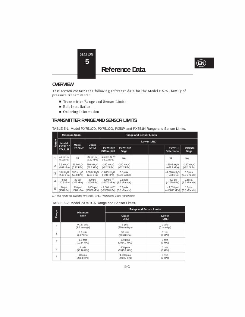
OVERVIEWThis section contains the following reference data for the Model PX751 family of pressure transmitters:
n Transmitter Range and Sensor Limitsn Bolt Installationn Ordering Information
TRANSMITTER RANGE AND SENSOR LIMITS
(1) This range not available for Model PX751P Reference Class Transmitters.
TABLE 5-1. Model PX751CD, PX751CG, PX751P, and PX751H Range and Sensor Limits.
Ran
ge
Minimum Sp an Range and Sensor Li mits
Model PX751 CD, CG, L, H
Model PX751P
Upper (URL)
Lower (LRL)
PX751C/P Differential
PX751C/P Gage
PX751HDiffer ential
PX751H Gage
1 0.5 inH2O(0.12 kPa)
NA25 inH2O(6.22 kPa)
–25 inH2O (1)
(–6.22 kPa)NA NA NA
2 2.5 inH2O (0.62 kPa)
25 inH2O(6.22 kPa)
250 inH2O(62.2 kPa)
–250 inH2O
(–62.2 kPa) –250 inH2O(–62.2 kPa)
–250 inH2O(–62.2 kPa)
–250 inH2O (–62.2 kPa)
3 10 inH2O (2.48 kPa)
100 inH2O (24.8 kPa)
1,000 inH2O (248 kPa)
–1,000 inH2O (–248 kPa)
0.5 psia
(3.5 kPa abs)
–1,000 inH2O
(–248 kPa)0.5 psia
(3.5 kPa abs)
4 3 psi (20.7 kPa)
30 psi (207 kPa)
300 psi (2070 kPa)
–300 psi (1)
(–2070 kPa)0.5 psia
(3.5 kPa abs)
–300 psi
(–2070 kPa)0.5 psia
(3.5 kPa abs)
5 20 psi (138 kPa)
200 psi (1380 kPa)
2,000 psi (13800 kPa)
– 2,000 psi (1)
(–13800 kPa)0.5 psia
(3.5 kPa abs)
– 2,000 psi (–13800 kPa)
0.5 psia (3.5 kPa abs)
TABLE 5-2. Model PX751CA Range and Sensor Limits.
Ran
ge Minimum Span
Range and S ensor Limits
Upper(URL)
Lower (LRL)
00.167 psia
(8.6 mmHga) 5 psia
(260 mmHga)0 psia
(0 mmHga)
10.3 psia
(2.07 kPa) 30 psia
(206.8 kPa) 0 psia
(0 kPa)
21.5 psia
(10.34 kPa) 150 psia
(1034.2 kPa) 0 psia
(0 kPa)
38 psia
(55.16 kPa) 800 psia
(5515.8 kPa) 0 psia
(0 kPa)
440 psia
(275.8 kPa) 4,000 psia
(27580 kPa) 0 psia
(0 kPa)
5-2
EN
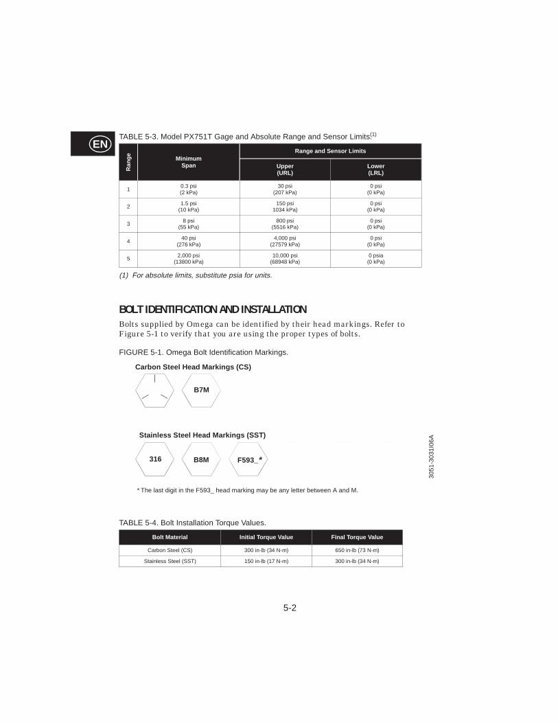
BOLT IDENTIFICATION AND INSTALLATIONBolts supplied by Omega can be identified by their head markings. Refer to Figure 5-1 to verify that you are using the proper types of bolts.
FIGURE 5-1. Omega Bolt Identification Markings.
(1) For absolute limits, substitute psia for units.
TABLE 5-3. Model PX751T Gage and Absolute Range and Sensor Limits(1).R
ange Minimum
Span
Range and S ensor Limits
Upper(URL)
Lower (LRL)
10.3 psi(2 kPa)
30 psi(207 kPa)
0 psi(0 kPa)
21.5 psi
(10 kPa)150 psi
1034 kPa)0 psi
(0 kPa)
38 psi
(55 kPa)800 psi
(5516 kPa)0 psi
(0 kPa)
440 psi
(276 kPa)4,000 psi
(27579 kPa)0 psi
(0 kPa)
52,000 psi
(13800 kPa) 10,000 psi
(68948 kPa)0 psia
(0 kPa)
TABLE 5-4. Bolt Installation Torque Values.
Bolt Material Initial Torque Value Final Torque Value
Carbon Steel (CS) 300 in-lb (34 N-m) 650 in-lb (73 N-m)
Stainless Steel (SST) 150 in-lb (17 N-m) 300 in-lb (34 N-m)
Stainless Steel Head Marki ngs (SST)
B7M
316 B8M F593_*
Carbon Steel Head Marki ngs (CS)
* The last digit in the F593_ head marking may be any letter between A and M.
3051
-303
1I06
A

APPENDIX
A-1
ENAHART® Communicator
OVERVIEWThe HART Communicator provides communication capabilities for Model PX751Smart Pressure Transmitters. The HART Communicator menu tree provides a schematic overview of configuration functions, and the fast key sequences provide direct access to software functions.
Online MenuThe Online menu appears automatically if the HART Communicator is connected to an active loop with an operating transmitter. From the Online menu, press the appropriate key sequence to access the desired function. Follow the on-screen instructions to complete the function.
FIGURE 1-1. HART Communicator Online Menu.
HART Fast Key FeatureThe fast key sequences for the HART Communicator use the following convention for their identification:
1 through 9–Refer to the keys located in the alphanumeric keypad located below the dedicated keypad.
NOTEHART fast key sequences are operational only from the Online menu. To access the Online menu from any other menu, select the HOME (F3) key.
HART Fast Key ExampleFast key sequences are made up of the series of numbers corresponding to the individual options in each step of the menu structure. For example, from the Online menu you can change the date. Following the menu structure, press 1 to reach Device Setup, press 3 for Basic Setup, press 4 for Device Info, press 1 for Date. The corresponding HART fast key sequence is 1, 3, 3, 1.
1250
A-2
EN
EN
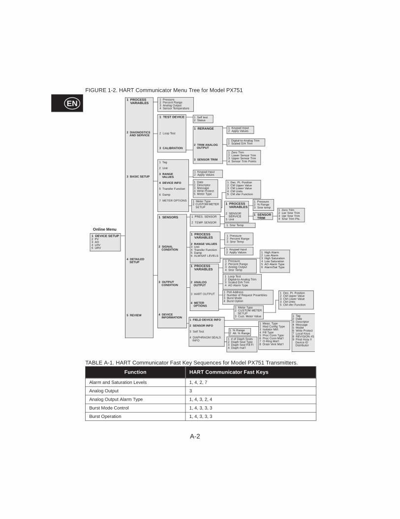
FIGURE 1-2. HART Communicator Menu Tree for Model PX751
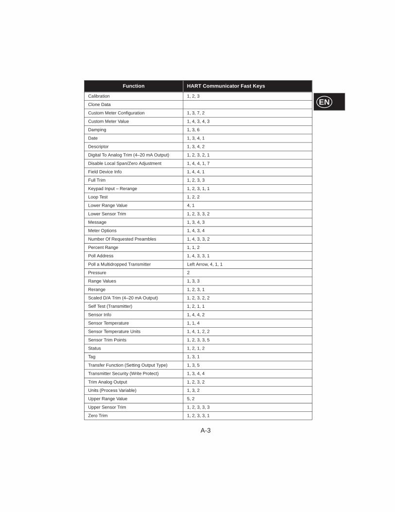
TABLE A-1. HART Communicator Fast Key Sequences for Model PX751 Transmitters.
Function HART Communicat or Fast Keys
Alarm and Saturation Levels 1, 4, 2, 7
Analog Output 3
Analog Output Alarm Type 1, 4, 3, 2, 4
Burst Mode Control 1, 4, 3, 3, 3
Burst Operation 1, 4, 3, 3, 3
1 Pressure2 Percent Range3 Analog Output4 Sensor Temperature
1 Tag
2 Unit
3 RANGEVALUES
4 DEVICE INFO
5 Transfer Function
6 Damp
7 METER OPTIONS
1 Self test2 Status
1 Keypad Input2 Apply Values
1 PROCESS VARIAB LES
2 RANGE VALUES3 Unit4 Transfer Function 5 Damp6 ALM/SAT LEVELS
1 Loop Test2 Digital-to-Analog Trim3 Scaled D/A Trim4 AO Alarm Type
1 Digital-to-Analog Trim2 Scaled D/A Trim
1 Zero Trim2 Lower Sensor Trim3 Upper Sensor Trim4 Sensor Trim Points
1 Date2 Descriptor3 Message4 Write Protect5 Meter Type
1 Keypad Input2 Apply Values
1 Pressure2 Percent Range3 Snsr Temp
1 Keypad Input2 Apply Values
1 Pressure2 Percent Range3 Analog Output4 Snsr Temp
1 DEVICE SETUP2 PV3 AO4 LRV5 URV
1 PROCESS VARIAB LES
2 DIAGNOSTICS AND SERVICE
3 BASIC SETUP
4 DETAILED SETUP
5 REVIEW
1 TEST DEVICE
2 Loop Test
3 CALIBR ATION
1 RERANGE
2 TRIM ANALOG OUTPUT
3 SENSOR TRIM
1 Pressure2 % Range3 Snsr temp
1 PROCESS VARIABL ES
2 SENSOR SERVICE
3 Unit
1 SENSOR TRIM
1 PROCESS VARIAB LES
2 ANALOG OUTPUT
3 HART OUTPUT
4 METER OPTIONS
Onlin e Menu
1 Zero Trim2 Lwr Snsr Trim3 Upr Snsr Trim4 Snsr Trim Pts.
1 PRES. SENSOR
2 TEMP. SENSOR1 Snsr Temp
1 SENSORS
2 SIGNAL CONDITION
3 OUTPUT CONDITION
4 DEVICE INFORMATION
1 % Range2 Alt. % Range
1 Meas. Type2 Mod Config Type3 Isolator Mtrl.4 Fill Type5 Proc Conn Type6 Proc Conn Mat’l7 O-Ring Mat’l8 Drain Vent Mat’l
1 Tag2 Date3 Descriptor4 Message5 Model6 Write Protect7 Local Keys8 REVISION #S9 Final Assy #
Device IDDistributor
1 Meter Type2 CUSTOM METER
SETUP
1 Dec. Pt. Position2 CM Upper Value3 CM Lower Value4 CM Units5 CM xfer Function
1 High Alarm2 Low Alarm3 High Saturation4 Low Saturation5 AO Alarm Type6 Alarm/Sat Type
1 Poll Address2 Number of Request Preambles3 Burst Mode4 Burst Option
1 Meter Type2 CUSTOM METER
SETUP3 Cust. Meter Value
1 Dec. Pt. Position2 CM Upper Value3 CM Lower Value4 CM Units5 CM xfer Function
1 FIELD DEVICE INFO
2 SENSOR INFO
3 Self Test
4 DIAPHRAGM SEALS INFO 1 # of Diaph Seals
2 Diaph Seal Type3 Diaph Seal Fill Fl4 Diaph mat’l
A-3
EN
ENCalibration 1, 2, 3
Clone Data
Custom Meter Configuration 1, 3, 7, 2
Custom Meter Value 1, 4, 3, 4, 3
Damping 1, 3, 6
Date 1, 3, 4, 1
Descriptor 1, 3, 4, 2
Digital To Analog Trim (4–20 mA Output) 1, 2, 3, 2, 1
Disable Local Span/Zero Adjustment 1, 4, 4, 1, 7
Field Device Info 1, 4, 4, 1
Full Trim 1, 2, 3, 3
Keypad Input – Rerange 1, 2, 3, 1, 1
Loop Test 1, 2, 2
Lower Range Value 4, 1
Lower Sensor Trim 1, 2, 3, 3, 2
Message 1, 3, 4, 3
Meter Options 1, 4, 3, 4
Number Of Requested Preambles 1, 4, 3, 3, 2
Percent Range 1, 1, 2
Poll Address 1, 4, 3, 3, 1
Poll a Multidropped Transmitter Left Arrow, 4, 1, 1
Pressure 2
Range Values 1, 3, 3
Rerange 1, 2, 3, 1
Scaled D/A Trim (4–20 mA Output) 1, 2, 3, 2, 2
Self Test (Transmitter) 1, 2, 1, 1
Sensor Info 1, 4, 4, 2
Sensor Temperature 1, 1, 4
Sensor Temperature Units 1, 4, 1, 2, 2
Sensor Trim Points 1, 2, 3, 3, 5
Status 1, 2, 1, 2
Tag 1, 3, 1
Transfer Function (Setting Output Type) 1, 3, 5
Transmitter Security (Write Protect) 1, 3, 4, 4
Trim Analog Output 1, 2, 3, 2
Units (Process Variable) 1, 3, 2
Upper Range Value 5, 2
Upper Sensor Trim 1, 2, 3, 3, 3
Zero Trim 1, 2, 3, 3, 1
Function HART Communicat or Fast Keys
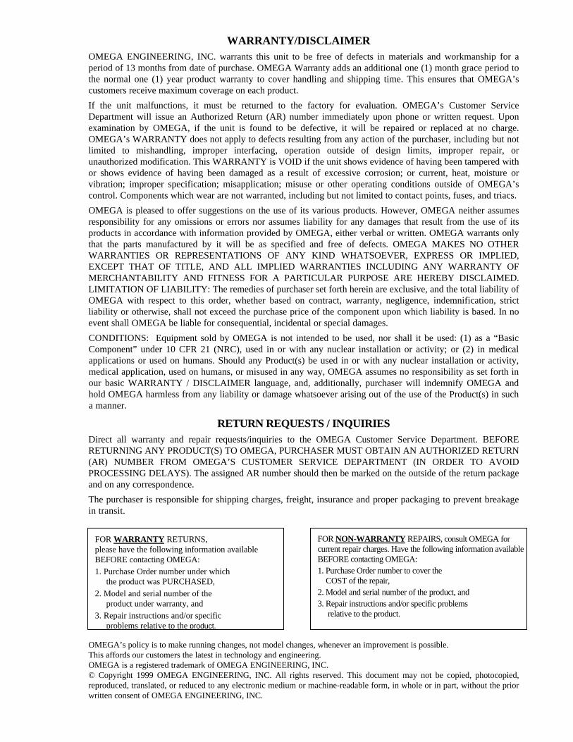
WARRANTY/DISCLAIMEROMEGA ENGINEERING, INC. warrants this unit to be free of defects in materials and workmanship for aperiod of 13 months from date of purchase. OMEGA Warranty adds an additional one (1) month grace period tothe normal one (1) year product warranty to cover handling and shipping time. This ensures that OMEGA’scustomers receive maximum coverage on each product.
If the unit malfunctions, it must be returned to the factory for evaluation. OMEGA’s Customer ServiceDepartment will issue an Authorized Return (AR) number immediately upon phone or written request. Uponexamination by OMEGA, if the unit is found to be defective, it will be repaired or replaced at no charge.OMEGA’s WARRANTY does not apply to defects resulting from any action of the purchaser, including but notlimited to mishandling, improper interfacing, operation outside of design limits, improper repair, orunauthorized modification. This WARRANTY is VOID if the unit shows evidence of having been tampered withor shows evidence of having been damaged as a result of excessive corrosion; or current, heat, moisture orvibration; improper specification; misapplication; misuse or other operating conditions outside of OMEGA’scontrol. Components which wear are not warranted, including but not limited to contact points, fuses, and triacs.
OMEGA is pleased to offer suggestions on the use of its various products. However, OMEGA neither assumesresponsibility for any omissions or errors nor assumes liability for any damages that result from the use of itsproducts in accordance with information provided by OMEGA, either verbal or written. OMEGA warrants onlythat the parts manufactured by it will be as specified and free of defects. OMEGA MAKES NO OTHERWARRANTIES OR REPRESENTATIONS OF ANY KIND WHATSOEVER, EXPRESS OR IMPLIED,EXCEPT THAT OF TITLE, AND ALL IMPLIED WARRANTIES INCLUDING ANY WARRANTY OFMERCHANTABILITY AND FITNESS FOR A PARTICULAR PURPOSE ARE HEREBY DISCLAIMED.LIMITATION OF LIABILITY: The remedies of purchaser set forth herein are exclusive, and the total liability ofOMEGA with respect to this order, whether based on contract, warranty, negligence, indemnification, strictliability or otherwise, shall not exceed the purchase price of the component upon which liability is based. In noevent shall OMEGA be liable for consequential, incidental or special damages.
CONDITIONS: Equipment sold by OMEGA is not intended to be used, nor shall it be used: (1) as a “BasicComponent” under 10 CFR 21 (NRC), used in or with any nuclear installation or activity; or (2) in medicalapplications or used on humans. Should any Product(s) be used in or with any nuclear installation or activity,medical application, used on humans, or misused in any way, OMEGA assumes no responsibility as set forth inour basic WARRANTY / DISCLAIMER language, and, additionally, purchaser will indemnify OMEGA andhold OMEGA harmless from any liability or damage whatsoever arising out of the use of the Product(s) in sucha manner.
RETURN REQUESTS / INQUIRIESDirect all warranty and repair requests/inquiries to the OMEGA Customer Service Department. BEFORERETURNING ANY PRODUCT(S) TO OMEGA, PURCHASER MUST OBTAIN AN AUTHORIZED RETURN(AR) NUMBER FROM OMEGA’S CUSTOMER SERVICE DEPARTMENT (IN ORDER TO AVOIDPROCESSING DELAYS). The assigned AR number should then be marked on the outside of the return packageand on any correspondence.
The purchaser is responsible for shipping charges, freight, insurance and proper packaging to prevent breakagein transit.
OMEGA’s policy is to make running changes, not model changes, whenever an improvement is possible.This affords our customers the latest in technology and engineering.OMEGA is a registered trademark of OMEGA ENGINEERING, INC.© Copyright 1999 OMEGA ENGINEERING, INC. All rights reserved. This document may not be copied, photocopied,reproduced, translated, or reduced to any electronic medium or machine-readable form, in whole or in part, without the priorwritten consent of OMEGA ENGINEERING, INC.
FOR WARRANTY RETURNS,please have the following information availableBEFORE contacting OMEGA:1. Purchase Order number under which the product was PURCHASED,2. Model and serial number of the product under warranty, and3. Repair instructions and/or specific problems relative to the product.
FOR NON-WARRANTY REPAIRS, consult OMEGA forcurrent repair charges. Have the following information availableBEFORE contacting OMEGA:1. Purchase Order number to cover the COST of the repair,2. Model and serial number of the product, and3. Repair instructions and/or specific problems relative to the product.

Where Do I Find Everything I Need forProcess Measurement and Control?
OMEGA…Of Course!
TEMPERATURE√√ Thermocouple, RTD & Thermistor Probes, Connectors, Panels & Assemblies√√ Wire: Thermocouple, RTD & Thermistor√√ Calibrators & Ice Point References√√ Recorders, Controllers & Process Monitors√√ Infrared Pyrometers
PRESSURE, STRAIN AND FORCE√√ Transducers & Strain Gauges√√ Load Cells & Pressure Gauges√√ Displacement Transducers√√ Instrumentation & Accessories
FLOW/LEVEL√√ Rotameters, Gas Mass Flowmeters & Flow Computers√√ Air Velocity Indicators√√ Turbine/Paddlewheel Systems√√ Totalizers & Batch Controllers
pH/CONDUCTIVITY
√√ pH Electrodes, Testers & Accessories√√ Benchtop/Laboratory Meters√√ Controllers, Calibrators, Simulators & Pumps√√ Industrial pH & Conductivity Equipment
DATA ACQUISITION√√ Data Acquisition & Engineering Software√√ Communications-Based Acquisition Systems√√ Plug-in Cards for Apple, IBM & Compatibles√√ Datalogging Systems√√ Recorders, Printers & Plotters
HEATERS√√ Heating Cable√√ Cartridge & Strip Heaters√√ Immersion & Band Heaters√√ Flexible Heaters√√ Laboratory Heaters
ENVIRONMENTAL MONITORING AND CONTROL√√ Metering & Control Instrumentation√√ Refractometers√√ Pumps & Tubing√√ Air, Soil & Water Monitors√√ Industrial Water & Wastewater Treatment√√ pH, Conductivity & Dissolved Oxygen Instruments M-3266/0799