Embed Size (px)
Citation preview

GRUNDOCRACK®
PNEUMATIC PIPE BURSTING SYSTEM
R E V I S I O N 3 . 0 • 0 8 . 1 6 . 0 2
User's Guide& Safety Manual
with replacement parts listings
TT Technologies,Inc.®
Copyright© 2002, TT Technologies, Inc.

1
WELCOME GRUNDOCRACK CUSTOMERThis pipe bursting manual is a product of years of actual field experience, from both TT Technologies staff andcontractors who have invested in pneumatic pipe bursting. This manual is designed to offer you a basicunderstanding of pipe bursting operations and safety procedures.
As with other trenchless methods, pipe bursting requires careful planning, preparation, and execution for desiredresults. Success in pipe bursting is dependent on using the proper equipment and incorporating the user informationfound in this manual. As in any construction process, quick fixes and oversights can result in failures and lost profits.
TT Technologies' staff has years of experience and offers the largest selection of pipe bursting tools and accessoriesin the industry. Consult with the TT staff when planning your bursting projects. In turn, please share your jobexperiences with our staff.
GRUNDOCRACK tools and pneumatic pipe bursting systems are designed to provide you with years of use.
MANUFACTURER'S STATEMENT OF USEAs a manufacturer of trenchless technology equipment for over 30 years, TT Technologies, Inc. does not discriminate against any potential customer. Unlike several pipe rehabilitation product manufacturers, TTTechnologies does not license the product which we manufacture, nor do we provide protected territories for ourequipment. Method licenses are issued by British Gas, and are required to operate pipe bursting tools.
TOOL LICENSING & ROYALTY REQUIREMENTSGRUNDOCRACK Pipe Bursting equipment and accessories are subject to an additional 5% royalty charge, notreflected in our pricing. TT Technologies will pass this royalty fee on to British Gas. This royalty charge does notapply to winches or winch booms. As the pipe bursting products are licensed under British Gas patents, you shouldtake this royalty fee into account. Upon purchase of this equipment, a British Gas representative will be contactingyou about signing you up as a British Gas method user licensee. For licensee details, contact your British Gasrepresentative: British Gas c/o Jim Hopwood
5444 West Heimer, Suite #1775Houston, TX 77056Phone: 713-622-7176 • Fax: 713-622-7244
Pipe bursting contractors operate under the following method patents: US 4738565, Canada 1195128
As a licensed manufacturer under British Gas equipment patents, TT Technologies operates under the followingequipment patents: US 4505302 & 4720211, Canada 1204294
DISCLAIMER FOR BURSTING MANUAL:NO WARRANTY AS TO MANUALTT Technologies makes no warranty that the information provided in this manual is complete, accurate in allrespects, or up to date. This manual should be used as a reference work to provide a starting point for addressingpipe bursting situations. Each particular situation is different. The user is responsible for providing the expertise andskill necessary to properly execute a given pipe-bursting job. TT Technologies specifically disclaims all express orimplied warranties concerning this manual, including the implied warranties of merchantability and fitness. In noevent shall TT Technologies be liable for consequential, special or incidental damages or contingent liabilities(including, without limitation, lost profits or goodwill, whether such claim arises in tort, contract, negligence, strictliability or any other basis) arising in any way out of the use of this manual.
LIMITED WARRANTY AS TO PRODUCTSTT provides a limited warranty to the original purchaser of its new products that new products will be free fromdefects in materials and workmanship for 90 days or 500 hours of actual use, whichever occurs first, provided theyare properly maintained serviced and used for the intended purpose of the product. (A one year warranty applies tothe barrel and piston, otherwise the period is as previously stated.) During the 90 day or 500 hours period, buyer'sremedies are limited to repair or replacement, at TT Technologies' discretion.
TT Technologies makes no other warranty, express or implied, and makes no warranty of merchantability or fitnessfor any particular purpose. No person, representative or agent of TT Technologies has the authority to change thiswarranty in any manner whatsoever. Any oral or written statements inconsistent with this limited warranty shall notapply.
In no event shall TT Technologies be liable for consequential, special or incidental damages or contingent liabilities(including, without limitation, lost profits or goodwill, whether such claim arises in tort, contract, negligence, strictliability or any other basis) arising in any way out of the use of any product or any parts thereof.
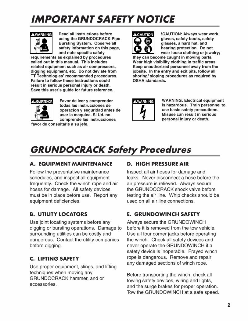
IMPORTANT SAFETY NOTICERead all instructions beforeusing the GRUNDOCRACK PipeBursting System. Observe allsafety information on this page, and note specific safety
requirements as explained by procedurescalled out in this manual. This includes related equipment such as air compressors,digging equipment, etc. Do not deviate fromTT Technologies’ recommended procedures.Failure to follow these instructions couldresult in serious personal injury or death.Save this user’s guide for future reference.
Favor de leer y comprendertodas las instrucciones deoperacion y seguridad antes deusar la maquina. Si Ud. no comprende las instrucciones
favor de consultarle a su jefe.
ADVERTADVERTENCIAENCIA
Instruccionesde Operación
!CAUTION: Always wear workgloves, safety boots, safetyglasses, a hard hat, and hearing protection. Do notwear loose clothing or jewelry;
they can become caught in moving parts.Wear high visibility clothing in traffic areas.Keep unauthorized personnel away from thejobsite. In the entry and exit pits, follow allshoring/ sloping procedures as required byOSHA standards.
WARNING: Electrical equipmentis hazardous. Train personnel touse basic safety precautions.Misuse can result in serious personal injury or death.
A. EQUIPMENT MAINTENANCEFollow the preventative maintenanceschedules, and inspect all equipment frequently. Check the winch rope and airhoses for damage. All safety devicesmust be in place before use. Report anyequipment deficiencies.
B. UTILITY LOCATORSUse joint locating systems before any digging or bursting operations. Damage tosurrounding utilities can be costly and dangerous. Contact the utility companiesbefore digging.
C. LIFTING SAFETYUse proper equipment, slings, and liftingtechniques when moving anyGRUNDOCRACK hammer, and oraccessories.
D. HIGH PRESSURE AIRInspect all air hoses for damage andleaks. Never disconnect a hose before theair pressure is relieved. Always securethe GRUNDOCRACK shock valve beforetesting the air line. Whip checks should beused on all air line connections.
E. GRUNDOWINCH SAFETYAlways secure the GRUNDOWINCHbefore it is removed from the tow vehicle.Use all four corner jacks before operatingthe winch. Check all safety devices andnever operate the GRUNDOWINCH if asafety device is inoperable. Frayed winchrope is dangerous. Remove and repairany damaged sections of winch rope.
Before transporting the winch, check alltowing safety devices, wiring and lights,and the surge brakes for proper operation.Tow the GRUNDOWINCH at a safe speed.
GRUNDOCRACK Safety Procedures
2

Table of Contents
General InformationA. About TT Technologies, Inc. . . . . . . . . . . . . . . . . . . . . . . . . . . . . . . . . . . . . . . . . . . . . . .5B. Pipe Bursting History . . . . . . . . . . . . . . . . . . . . . . . . . . . . . . . . . . . . . . . . . . . . . . . . . . . .5C. GRUNDOCRACK Application Checklist . . . . . . . . . . . . . . . . . . . . . . . . . . . . . . . . . . . . .6
Job Parameters and ConditionsA. Host Pipe Materials Suitable for Pipe Bursting . . . . . . . . . . . . . . . . . . . . . . . . . . . . . . . .6B. Host Pipe Size . . . . . . . . . . . . . . . . . . . . . . . . . . . . . . . . . . . . . . . . . . . . . . . . . . . . . . . . .7C. Host Pipe Depth . . . . . . . . . . . . . . . . . . . . . . . . . . . . . . . . . . . . . . . . . . . . . . . . . . . . . . .7D. Surrounding Soil Types . . . . . . . . . . . . . . . . . . . . . . . . . . . . . . . . . . . . . . . . . . . . . . . . . .8E. New Material & Size . . . . . . . . . . . . . . . . . . . . . . . . . . . . . . . . . . . . . . . . . . . . . . . . . . . .8F. Peripheral Utilities . . . . . . . . . . . . . . . . . . . . . . . . . . . . . . . . . . . . . . . . . . . . . . . . . . . . . .9G. Service Excavations . . . . . . . . . . . . . . . . . . . . . . . . . . . . . . . . . . . . . . . . . . . . . . . . . . . .9H. Start & Exit Pits . . . . . . . . . . . . . . . . . . . . . . . . . . . . . . . . . . . . . . . . . . . . . . . . . . . . . . . .9I. Manhole Preparation . . . . . . . . . . . . . . . . . . . . . . . . . . . . . . . . . . . . . . . . . . . . . . . . . . . .10J. Burst Length . . . . . . . . . . . . . . . . . . . . . . . . . . . . . . . . . . . . . . . . . . . . . . . . . . . . . . . . . .11
Expander TypesA. Rear Expanders . . . . . . . . . . . . . . . . . . . . . . . . . . . . . . . . . . . . . . . . . . . . . . . . . . . . . . .11B. Front Expanders . . . . . . . . . . . . . . . . . . . . . . . . . . . . . . . . . . . . . . . . . . . . . . . . . . . . . .13C. Nose Attachment Units . . . . . . . . . . . . . . . . . . . . . . . . . . . . . . . . . . . . . . . . . . . . . . . . .13
Mini Hammer UsesA. Mini-Atlas . . . . . . . . . . . . . . . . . . . . . . . . . . . . . . . . . . . . . . . . . . . . . . . . . . . . . . . . . . . .14B. Mini-Olympus . . . . . . . . . . . . . . . . . . . . . . . . . . . . . . . . . . . . . . . . . . . . . . . . . . . . . . . . .14C. Mini-Gigant . . . . . . . . . . . . . . . . . . . . . . . . . . . . . . . . . . . . . . . . . . . . . . . . . . . . . . . . . .14
Air Supply and Related ItemsA. Compressor Requirements . . . . . . . . . . . . . . . . . . . . . . . . . . . . . . . . . . . . . . . . . . . . . .15B. Air Supply Components . . . . . . . . . . . . . . . . . . . . . . . . . . . . . . . . . . . . . . . . . . . . . . . . .15
Bentonite UsesA. General . . . . . . . . . . . . . . . . . . . . . . . . . . . . . . . . . . . . . . . . . . . . . . . . . . . . . . . . . . . . .18B. Conditions Requiring Use of Bentonite . . . . . . . . . . . . . . . . . . . . . . . . . . . . . . . . . . . . .18C. Selection of Bentonite & Pumping Equipment . . . . . . . . . . . . . . . . . . . . . . . . . . . . . . . .18D. Line and Port Installation . . . . . . . . . . . . . . . . . . . . . . . . . . . . . . . . . . . . . . . . . . . . . . . .19E. Pump Operation/Mixing . . . . . . . . . . . . . . . . . . . . . . . . . . . . . . . . . . . . . . . . . . . . . . . . .20F. Standard Use During the Burst . . . . . . . . . . . . . . . . . . . . . . . . . . . . . . . . . . . . . . . . . . .20
The GRUNDOWINCH RoleA. GRUNDOWINCH Specifications . . . . . . . . . . . . . . . . . . . . . . . . . . . . . . . . . . . . . . . . . .21B. GRUNDOWINCH Setup . . . . . . . . . . . . . . . . . . . . . . . . . . . . . . . . . . . . . . . . . . . . . . . .22C. GRUNDOWINCH Boom Setup . . . . . . . . . . . . . . . . . . . . . . . . . . . . . . . . . . . . . . . . . . .23
1.
2.
3.
4.
5.
6.
3
7.

4
Burst Preparation–Typical Bursting SetupA. Entry & Exit Pits . . . . . . . . . . . . . . . . . . . . . . . . . . . . . . . . . . . . . . . . . . . . . . . . . . . . . . .25B. Installation of Winch Rope in Host Pipe . . . . . . . . . . . . . . . . . . . . . . . . . . . . . . . . . . . . .25C. GRUNDOWINCH/Hammer Coordination . . . . . . . . . . . . . . . . . . . . . . . . . . . . . . . . . . .26
The Bursting ProcessA. Starting the Burst . . . . . . . . . . . . . . . . . . . . . . . . . . . . . . . . . . . . . . . . . . . . . . . . . . . . . .26B. Speed of the Burst . . . . . . . . . . . . . . . . . . . . . . . . . . . . . . . . . . . . . . . . . . . . . . . . . . . . .26C. Monitoring the Burst . . . . . . . . . . . . . . . . . . . . . . . . . . . . . . . . . . . . . . . . . . . . . . . . . . .27D. Burst Completion . . . . . . . . . . . . . . . . . . . . . . . . . . . . . . . . . . . . . . . . . . . . . . . . . . . . . .27E. Hammer/Expander Removal . . . . . . . . . . . . . . . . . . . . . . . . . . . . . . . . . . . . . . . . . . . . .27F. PE Connection to the Manhole . . . . . . . . . . . . . . . . . . . . . . . . . . . . . . . . . . . . . . . . . . .28G. Service Connections . . . . . . . . . . . . . . . . . . . . . . . . . . . . . . . . . . . . . . . . . . . . . . . . . . .29
Special ApplicationsA. Manhole Removal . . . . . . . . . . . . . . . . . . . . . . . . . . . . . . . . . . . . . . . . . . . . . . . . . . . . .29B. Windowing—Exit Manhole (10" and Smaller PE) . . . . . . . . . . . . . . . . . . . . . . . . . . . . .30C. Windowing—Entrance Manhole . . . . . . . . . . . . . . . . . . . . . . . . . . . . . . . . . . . . . . . . . .32D. Straight Barrel Removal (PCG Tools) . . . . . . . . . . . . . . . . . . . . . . . . . . . . . . . . . . . . . .34E. Lateral Pipe Replacement . . . . . . . . . . . . . . . . . . . . . . . . . . . . . . . . . . . . . . . . . . . . . . .35
AppendicesA. GRUNDOCRACK Application Checklist . . . . . . . . . . . . . . . . . . . . . . . . . . . . . . . . . . . .36B. Welding Procedure to Install Cutting Blades to Expander . . . . . . . . . . . . . . . . . . . . . . .37C. Hard Surface Procedure (Maintenance of Expanders) . . . . . . . . . . . . . . . . . . . . . . . . .37D. Shock Valve Cleaning & Disassembly . . . . . . . . . . . . . . . . . . . . . . . . . . . . . . . . . . . . . .38E. Non-TT Supplied Equipment for Pipe Bursting Jobs . . . . . . . . . . . . . . . . . . . . . . . . . . .39F. Standard DIPS Dimensions & Working Pressure Ratings (WPR) . . . . . . . . . . . . . . . . .39G. Minimum Bend Radius Calculations for HDPE Pipe . . . . . . . . . . . . . . . . . . . . . . . . . .39H. HDPE Pipe Size & Dimension Charts . . . . . . . . . . . . . . . . . . . . . . . . . . . . . . . . . . . . . .40I. Parts List for PCF 130 Tool . . . . . . . . . . . . . . . . . . . . . . . . . . . . . . . . . . . . . . . . . . . . . . .45J. Parts List for PCF 145 Tool . . . . . . . . . . . . . . . . . . . . . . . . . . . . . . . . . . . . . . . . . . . . . .46K. Parts List for PCF 180 Tool . . . . . . . . . . . . . . . . . . . . . . . . . . . . . . . . . . . . . . . . . . . . . .47L. Parts List for PCF 220 Tool . . . . . . . . . . . . . . . . . . . . . . . . . . . . . . . . . . . . . . . . . . . . . .48M. Parts List for 130 Mini-Atlas Tool . . . . . . . . . . . . . . . . . . . . . . . . . . . . . . . . . . . . . . . . .49N. Parts List for 180 Mini-Olympus Tool . . . . . . . . . . . . . . . . . . . . . . . . . . . . . . . . . . . . . .50O. Parts List for 180 Olympus Tool . . . . . . . . . . . . . . . . . . . . . . . . . . . . . . . . . . . . . . . . . .51P. Parts List for 220 Hercules Tool . . . . . . . . . . . . . . . . . . . . . . . . . . . . . . . . . . . . . . . . . .52Q. Parts List for 260 Mini-Gigant Tool . . . . . . . . . . . . . . . . . . . . . . . . . . . . . . . . . . . . . . . .53R. Parts List for 260 Gigant Tool . . . . . . . . . . . . . . . . . . . . . . . . . . . . . . . . . . . . . . . . . . . .54S. Parts List for 350 Koloss Tool . . . . . . . . . . . . . . . . . . . . . . . . . . . . . . . . . . . . . . . . . . . .55T. Parts List for 450 Goliath Tool . . . . . . . . . . . . . . . . . . . . . . . . . . . . . . . . . . . . . . . . . . . .56U. Parts List for 600 Taurus Tool . . . . . . . . . . . . . . . . . . . . . . . . . . . . . . . . . . . . . . . . . . . .57V. Parts List for PCG 130 Tool . . . . . . . . . . . . . . . . . . . . . . . . . . . . . . . . . . . . . . . . . . . . . .58W. Parts List for PCG 145 Tool . . . . . . . . . . . . . . . . . . . . . . . . . . . . . . . . . . . . . . . . . . . . .59X. Parts List for PCG 180 Tool . . . . . . . . . . . . . . . . . . . . . . . . . . . . . . . . . . . . . . . . . . . . . .60Y. Parts List for HV 220 Tool . . . . . . . . . . . . . . . . . . . . . . . . . . . . . . . . . . . . . . . . . . . . . . .61Z. Parts List for PCG 270 Tool . . . . . . . . . . . . . . . . . . . . . . . . . . . . . . . . . . . . . . . . . . . . . .62AA. Parts List for KV 350 Tool . . . . . . . . . . . . . . . . . . . . . . . . . . . . . . . . . . . . . . . . . . . . . .63
8.
9.
10.
11.

5
General InformationA. ABOUT TT TECHNOLOGIES, INC.For more than 30 years, TT Technologies and Tracto-Technik have beenleaders in trenchless replacement systems beginning with pneumaticpiercing tools. Today, with more than 200 patents worldwide, TTTechnologies tools are used in trenchless applications ranging from pipepulling, pipe ramming, slip-lining, directional drilling and pipe bursting.
The use of pneumatic tools in the pipe bursting application was developedin a joint effort between British Gas Co. and Tracto-Technik, TTTechnologies’ European counterpart. The quality of this TT Technologiessystem, combined with the experience of our people will provide you withmany years of safe, trouble-free operation of your new GRUNDOCRACKsystem.
As with all construction operations, safe operational procedures must beobserved. The safety alert symbol is used in this manual to advise you ofthe potential for bodily injury or death.
B. PIPE BURSTING HISTORYDeveloped by British Gas, pipe bursting is a “generic” term used todescribe a process of cracking or bursting an old pipe, called the hostpipe, and replacing it with a new product pipe of the same or largerdiameter. This patented process is used to replace sewer, water, gas,storm sewer, telephone, power and chemical production industrial lines(Figure 1).
The GRUNDOCRACK system uses a pneumatic hammer combined withthe proper size soil expander and a specially designed winch. Theselection of the proper system components is dependent on various jobparameters. TT Technologies documents job conditions and equipmentusage and maintains this history for customer use.
1.
GRUNDOWINCH®
Exit Pit
Entry Pit
GRUNDOWINCH®
Exit Pit
Entry Pit
Winch LineWinch Line Rear ExpanderRear Expander
GRUNDOCRACK®GRUNDOCRACK®
Old PipeOld Pipe
CompressorCompressor
New PE PipeNew PE Pipe
Figure 1. Typical GRUNDOCRACK Setup

6
C. GRUNDOCRACK APPLICATION CHECKLISTA checklist for GRUNDOCRACK applications is available to users to document specific job parameters. This checklist can be reviewed by TTTechnologies product specialists for feasibility and equipment recommendations. We recommend this checklist be completed andreviewed prior to job commitment. A sample of this checklist is includedin Appendix A, pg 36.
Job Parameters andConditionsA. HOST PIPE MATERIALS SUITED TO THE PIPE BURSTING
PROCESS1) Vitreous Clay Tile-used in diameters
from 4" up, clay tile is a common material used in sewer, telephone andpower systems. The ability to fracturethe pipe and compact fragments intothe surrounding soil make it an idealhost pipe. Some concrete reinforcedpoint repairs may slow or stop thebursting process (Figure 2). Newerclay pipe may use PVC gasket or elastomeric sealing material whichmust be cut during the burst. Aschnozz with cutting blades and expander is recommended for this situation.
2) Concrete Pipe-used in all applications except gas distribution, concrete pipewill have various degrees of reinforcement ranging from wire mesh to steelreinforcement rods. The amount of reinforcement will determine the systemselection and burst success probabilities. Reinforced concrete pipe to 48"diameter has been burst. Heavily reinforced pipe may require additionalcover to prevent surface disruption.
3) Cast Iron Pipe-used in all applicationsexcept telephone. Cast iron fractureswell, but requires special lead equipment to protect the winch ropefrom possible damage. Bell and spigottype joints require a blade-type noseextension to help crack the large crosssection of material contained in thesejoints. Product pipe of at least SDR 17rating should be used to prevent sharpparticles from damaging the newinstallation (Figure 3). Ductile Iron andsome stainless steel repair clampsmay resist bursting and requireremoval prior to or during the burst.
2.
Figure 2.
Figure 3.

4) Plastic, including PVC, ABS, PE, etc. - possess varying degrees of “burstability,” due to material composition. Most plastic pipe must be split intoribbons using special knife blade equipped nose extensions. The limited ability to fracture these materials into small pieces limits the soil expansionand increases the friction on the product pipe, sometimes reducing the burstlength.
5) Transite (asbestos cement) - used in all applications, transite has good bursting potential, similar to clay tile. It is particularly beneficial to burst thispipe, since excavation presents exposure to hazardous asbestos.
B. HOST PIPE SIZEHost pipe size will affect bothhammer/expander combinations andwinch selection. Small diameter hostpipe in difficult soil conditions can presentproblems because a larger, more powerful hammer will not fit inside thehost pipe. Special nose tools can beadapted to solve these problems(Figure 4). Changes in host pipediameter in a single run can cause gradeproblems.
Identify specific conditions within the host pipe before bursting. Forexample, bad joints, cracks, collapsed sections, line sags, etc. All projectsshould be video taped before bursting. Any project that cannot be videotaped before bursting is considered a risk.
C. HOST PIPE DEPTHThe depth of the host pipe affects the bursting process in the following manner:
1). In some cases the deeper the host pipe, the more difficult the soilexpansion process becomes due to the additional weight and densityof the surrounding soil.
2). As depth increases the “overcut” (difference between the OD of thePE pipe diameter and the OD of the expander diameter) may have tobe increased to provide an adequate space for installation of the newpipe (Figure 5).
3). Start and exit pits size increases with depth, as well as shoring,digging equipment and safety procedures.
7
Figure 4. Special Nose Tools
BA GRUNDOCRACK® Tool Expander New PE
B - A = UPSIZE
A=ID of Host Pipe
B=OD of Expander
Overcut
Overcut= Distance between OD of Expanderand OD of New PE Pipe, or annular space.
Figure 5. “Overcut” Example
4). De-watering procedures change with depth, requiring additionalequipment.
5). Changes in host pipe profile-due to the inability of the tool assemblyto “bend,” grade angles cannot be burst and must be exposed.
6). RULE OF THUMB: To determine the Minimum Required Depth, subtract the host pipe size from the OD of the expander. Multiply theresult by 10. Example: 14" host pipe, 18" Grundocrack with 20"HDPE (DIPS) and 24" OD expander. 24" - 14" = 10" 10" x 10 = 100" minimum depth
In more compacted soil such as cemented cobble, minimumdepth must be increased.
Note: Be aware of pipe measurements in either IPS or DIPS. Use one measurement system when performing calculations.
D. SURROUNDING SOIL TYPESSince most of this country’s utilities were originally installed by some open cutmethod, at least the top of the host pipe is covered with fill material. In addition,the soil need not be removed, only compacted. Extreme conditions, however,will affect the speed and length of the burst. Extremely hard clay, 80 to 100 blowcount densities, will slow the bursting process due to the additional forcerequired to “open” the hole and expand the soil.
Some soils will not remain in the expanded state long enough to allow installation of the new product pipe. In this case, the use of bentonite and polymers can help. Host pipes located below the water table in sand are difficult.The sand is fluid like and grips the HDPE product pipe, increasing friction rapidly.
The host pipe soil bed must be capable of supporting the weight of thetool/expander and product pipe. A pre-burst video may show voids or washoutsto be considered. Repairs or pipe collapse may also be viewed in the video.
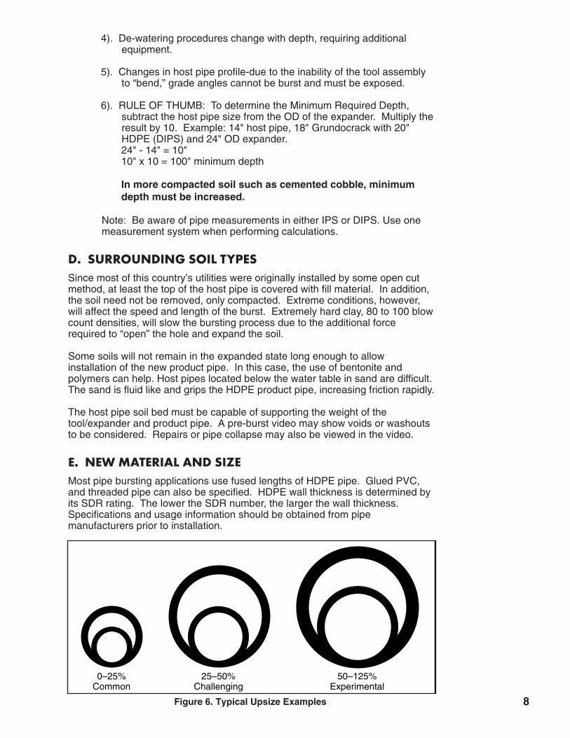
E. NEW MATERIAL AND SIZEMost pipe bursting applications use fused lengths of HDPE pipe. Glued PVC,and threaded pipe can also be specified. HDPE wall thickness is determined byits SDR rating. The lower the SDR number, the larger the wall thickness.Specifications and usage information should be obtained from pipe manufacturers prior to installation.
8
0–25%Common
25–50%Challenging
50–125%Experimental
Figure 6. Typical Upsize Examples

The ability to “upsize” or install a product pipe larger than the host pipe is uniqueto pipe bursting. The amount of upsize is limited by a combination of all the hostpipe parameters. Host pipe diameters of 12" and smaller can be upsized by50% (4" to 6", 6" to 10", 8" to 12") under most situations. Due to the large volume of soil to be compacted in diameters larger than 12", the percent ofupsize may not be as large (Figure 6). Another consideration of the new pipeinstallation is the projected weight of the total installation. Refer to the chart of100' lengths of various diameter HDPE at SDR 17 (Figure 7) for pipe weights.
Using 36" SDR 17 HDPE on a 400 ft. burst as an example, the weight of the PEalone would approach 40,000 lbs. The weight of the pipe, thehammer/expander, and friction of the soil all add to the bursting equation.
Locate utilities before your dig. GRUNDOCRACK tool contact with power cable cancause injury or death.
F. PERIPHERAL UTILITIESUtilities near the start and exit pits and along the burst route must be locatedand, in some cases, exposed prior to bursting. Since start and exit pits and service connections must be excavated, good locates are necessary as with anyunderground operation.
G. SERVICE EXCAVATIONSIn sewer applications, services or laterals are located by video inspection of theline. In gas applications, electronic locating devices are used. It is recommended all services and laterals be exposed prior to bursting to avoiddamage and to reduce service downtime. An exception to this is when bentoniteis being used. The service pit should be dug after the burst to prevent filling withbentonite. Keep these service pits as small as possible to avoid affects onthe grade of the new pipe. Service connections, fittings and equipment areavailable from various suppliers. Contact TT Technologies for a list of suppliers.
H. START AND EXIT PITSIn sewer applications, pits are usually located in front of manholes to allow gradual entry of hammer/expander and new pipe into the host pipe. A steepentry will place unnecessary strain on the product pipe as it enters the pit.Damaged HDPE pipe, incomplete burst, or pipe not on grade could result (Figures 8 and 9). HDPE pipe can be bent to minimum bend radius approxi-mately 20 to 40 times the pipe diameter. For exact minimum bend requirementssee Minimum Bend Radius Calculations in Appendix G, pg 39.
Pneumatic tool must be launched level, not pointing down otherwise grade canbe affected.
9
PIPE SIZE VS. WEIGHT
PIPE SIZEPIPE WEIGHT(lbs. per ft.)
PIPE WEIGHT(lbs. per 100 ft.)
8" SDR 17 5.65 56510" SDR 17 8.78 87812" SDR 17 12.36 123620" SDR 17 30.42 304236" SDR 17 98.56 9856
Figure 7.
DANGER

Exit pits are sized to facilitate removal of the hammer/expander and allow manhole connections to the new product pipe. Reversible tools can be used insome applications, thus eliminating the exit pit.
For gas and water bursting operations, the service excavations can be used asstart and exit pits as needed.
Prepare all pits in a safe and approved manner.
I. MANHOLE PREPARATIONAll confined space safety procedures apply.
Entry and exit holes must be enlarged to accept the expander and new productpipe as required. Sewer manhole inverts may need modification to allow toolpassage and to allow new pipe to remain on grade (Figure 10).
Note: If tool will deflect at invert while going through intermediatemanholes then invert must be taken out to avoid affecting grade.
Note: Anytime there is less pressure above the bursting tool and aconcrete or dense soil below, grade can be affected.
10
Figure 8. Incorrect; too steepof bend on PE pipe.
Figure 9. Correct; gradual bend on PE pipe.
GRUNDOWINCH®
Exit Pit
Entry Pit
GRUNDOWINCH®
Exit Pit
Entry Pit
Winch LineWinch Line Rear ExpanderRear Expander
GRUNDOCRACK®GRUNDOCRACK®
Old PipeOld Pipe
CompressorCompressor
New PE PipeNew PE Pipe
Figure 10. Typical GRUNDOCRACK Jobsite

J. BURST LENGTHMost proposed sewer bursts are manhole to manhole, but at times it is necessary to extend the burst through an intermediate manhole. The success ofthis additional length is dependent on the following conditions.
The intermediate manhole must be prepared to provide as little resistance aspossible. In some cases a larger overcutwill be necessary to provide additionalannular space to reduce new product pipefriction.
If the manhole is to be passed throughthe invert must be removed and enlargedto prevent the hammer/expander fromrising in the manhole and adding a speedbump (Figure 11).
The use of bentonite is always recommended as a method to increase the burstlength, regardless of the host pipe diameter. See “Bentonite Uses” pg. 18.
Bursts performed in similar conditions may give an indication of the total lengthexpected. Documentation is recommended for each bursting project. This information is valuable for later reference in job planning. Contact a TTTechnologies product specialist for information on bursting projects completedworldwide.
Expander TypesA. REAR EXPANDERSRear expanders slide over the main bodyof the GRUNDOCRACK bursting tool andare held in position by the hammer’sflared end (Figure 12). The PE pipe isfixed to the rear of the expander by oneof the following methods:
1. Rear Threaded ExpanderThe supplied PE link is first fused to thePE train. The expander is then rotated toengage the threads on the link. Be careful not to cross thread the expanderand link. A strap wrench/spanner wrenchcombination is used to complete theprocess (Figures 13 and 14). Useful in“wet applications” to prevent water intrusion into new pipe and tool.
11
3.
Host Pipe
Invert
LargerOvercut
Figure 11. Intermediate Manhole
Figure 12. Rear Expander
Figure 13. Rear Threaded Expander

2. Gland Nut A-Style TypeRear expanders using the gland nut havea special PE link. This link has amachined shoulder that is held in place bythe gland nut. The PE link is fused to thePE train with the gland nut facing theexpander. A shock ring is used betweenthe rear of the expander and the glandnut to prevent thread damage. A steelinsert is placed in the PE link to provide additional strength (Figures 15 and 16).
3. Direct Bolt & Strap Type Direct Bolt Rear expanders provide forthe PE pipe to be inserted into thebackside of the expander. Flat headscrews are installed through tapped holesin the expander through drilled holes inthe PE pipe (Figure 17).
Strap Type Expanders utilize a spline thatis inserted through an access port in theexpander. The spline interlocks groovesin the ID of the expander and the OD ofthe PE link. (Figure 18).
12
��� ��� ��� ��� ��� ��� ��� ��� ��� ��� ��� ��� ��� ��� ��� ��� ��� ��� ��� ��� ��� ��� ��� ��� ��� ��� ��� ��� ��� ��� ��� ��� ��� ��� ��� ��� ��� ��� ��� ��� ��� ��� ��� ��� ��� ��� ��� ��� ��� ��� ��� ��� ��� ��� ��� ��� ��� ��� ��� ��� ��� ��� ��� ��� ��� ��� ��� ��� ��� ��� ��� ��� ��� ��� ��� ��� ��� ��� ��� ��� ��� ��� ��� ��� ��� ��� ��� ��� ��� ��� ��� ��� ��� ��� ��� ��� ��� ��� ��� ��� ��� ��� ��� ��� ��� ��� ��� ��� ��� ��� ��� ��� ��� ��� ��� ��� ��� ��� ��� ��� ��� ��� ��� ��� ��� ��� ��� ��� ��� ��� ��� ��� ��� ��� ��� ��� ��� ��� ��� ��� ��� ��� ��� ��� ��� ��� ��� ��� ��� ��� ��� ��� ��� ��� ��� ��� ��� ��� ��� ��� ���Figure 14. Rear Threaded Expander Assembly
Figure 15. Gland Nut A-StyleRear Expander
��������������������������������������������������������������������������������������������������������������������������������������������������������������������������������������������������������������������������������������������������������������������������������������������������������������������������������������������������������������������������������������������������������������������������������������������������������������������������������������������������������������������������������������������������������������������������������������������������������������������������������������������������������������������
Figure 16. Gland Nut A-Style Rear Expander Assembly
��� ��� ��� ��� ��� ��� ��� ��� ��� ��� ��� ��� ��� ��� ��� ��� ��� ��� ��� ��� ��� ��� ��� ��� ��� ��� ��� ��� ��� ��� ��� ��� ��� ��� ��� ��� ��� ��� ��� ��� ��� ��� ��� ��� ��� ��� ��� ��� ��� ��� ��� ��� ��� ��� ��� ��� ��� ��� ��� ��� ��� ��� ��� ��� ��� ��� ��� ��� ��� ��� ��� ��� ��� ��� ��� ��� ��� ��� ��� ��� ��� ��� ��� ��� ��� ��� ��� ��� ��� ��� ��� ��� ��� ��� ��� ��� ��� ��� ��� ��� ��� ��� ��� ��� ��� ��� ��� ��� ��� ��� ��� ��� ��� ��� ��� ��� ��� ��� ��� ��� ��� ��� ��� ��� ��� ��� ��� ��� ��� ��� ��� ��� ��� ��� ��� ��� ��� ��� ��� ��� ��� ��� ��� ��� ��� ��� ��� ��� ��� ��� ��� ��� ��� ��� ��� ��� ��� ��� ��� ��� ����������������������������������������������������������������������������������������������������������������������������������������������������������������������������������������������������������������������������������������������������������������������������������������������������������������������������������������������������������������������������������������������������������������������������������������������������������������������������������������������������������������������������������������������������������������������������������������������������������������������������������������������������������������������������������������������������������������������������������������������������������������������������������������������������������������������������������������Figure 18. Strap Type Rear Expander Assembly
��� ��� ��� ��� ��� ��� ��� ��� ��� ��� ��� ��� ��� ��� ��� ��� ��� ��� ��� ��� ��� ��� ��� ��� ��� ��� ��� ��� ��� ��� ��� ��� ��� ��� ��� ��� ��� ��� ��� ��� ��� ��� ��� ��� ��� ��� ��� ��� ��� ��� ��� ��� ��� ��� ��� ��� ��� ��� ��� ��� ��� ��� ��� ��� ��� ��� ��� ��� ��� ��� ��� ��� ��� ��� ��� ��� ��� ��� ��� ��� ��� ��� ��� ��� ��� ��� ��� ��� ��� ��� ��� ��� ��� ��� ��� ��� ��� ��� ��� ��� ��� ��� ��� ��� ��� ��� ��� ��� ��� ��� ��� ��� ��� ��� ��� ��� ��� ��� ��� ��� ��� ��� ��� ��� ��� ��� ��� ��� ��� ��� ��� ��� ��� ��� ��� ��� ��� ��� ��� ��� ��� ��� ��� ��� ��� ��� ��� ��� ��� ��� ��� ��� ��� ��� ��� ��� ��� ��� ��� ��� ���Figure 17. Direct Bolt Rear Expander Assembly

B. FRONT EXPANDERSFront expanders fit on the hammers’tapered nose cone. The PE pipe isattached by using a threaded PE link ordirect bolt style expanders. The PEpipe’s inner diameter must be largeenough to fit over the hammer(Figures 19 and 20).
Front expanders can be used to burst thehost pipe and then enter the exit manhole.A straight-barrel hammer can be removed by putting the tool in reverse andbacking it out of the newly installed pipe. For step by step illustrations of Frontexpanders on reversible PCG tools, see Appendix D, Page 34.
��������������������������������������������������������������������������������������������������������������������������������������������������������������������������������������������������������������������������������������������������������������������������������������������������������������������������������������������������������������������������������������������������������������������������������������������������������������������������������������������������������������������������������������������������yyyyyyyyyy ��������������������������������������������������������������������������������������������������������������������������������������������������������������������������������������������������������������������������������������������������������������������������������������������������������������������������������������������������������������������������������������������������������������������������������������������������������������������������������������������������������������������������������������������������yyyyyyyyyy
Figure 24. Guide Head (Schnozz) with Cable Hook up and Steel Pin Assembly.Fits on Rammer Style Pipe Bursting Tools with Pulling Eye
Figure 19. Front Expander
�����������������������������������������������������������������������������������������������������������������������������������������������������������������Figure 20. Front Expander Assembly
13
Figure 22. Guide Head (Schnozz) with Cable Hook up and Steel Pin
C. NOSE ATTACHMENT UNITS (GUIDE HEAD ASSEMBLY)During the bursting process, pieces of thehost pipe will often break ahead of the tooland fall in front of the hammer. If thesepieces are not pushed aside, the tool willslow down or may even come to a fullstop. An extension is attached to thehammer’s nose to prevent this (Figures21–24). This also eliminates the need forbolts or roll pins. Shorter set-up anddisassembly times are also possible.
Figure 23. Guide Head (Schnozz) withCable Hook up & Steel Pin Assembly.
Figure 21. Nose Extension Assembly

14
Mini-Hammer UsesThe GRUNDOCRACK product line includes three mini-hammers:
A. MINI-ATLAS Used to burst service pipe and to install new 4" and 6" PE. The reducedlength of the tool allows for smaller pits. In some applications, the tool can beremoved from a manhole after the burst is complete (Figures 25 A & B).
B. MINI-OLYMPUSUsed to burst 8" and 10" pipe. Shorter pits can be used and in someapplications, the tool can be removed from a manhole after the burst iscomplete.
C. MINI-GIGANTUsed to burst 12" and 14" pipes and replaces 12" and 14" PE. This tool cannotbe removed from a manhole due to its length and weight, but the pit size will beconsiderably smaller.
������������
������������
������������
������������
����������������
����������������
���������
���������
���������
�����������������
����������������
Figure 25 A & B. Mini-Atlas manhole entrance and exit.
4.

GRUNDOCRACK Air Supplyand Related ItemsA. COMPRESSOR REQUIREMENTS - MINIMUM CFMAll tools should be operated with a compressor outlet pressure of 110-115 psi.Supply hoses provided by TT Technologies are sized to operate the GRUNDOCRACK hammer efficiently and should not be reduced in any manner (Figure 26).
Note: Air pressure will drop approximately 2.5 psi per 100' of air hose.
Incorrect hoses may fail. Ensure all hosesare properly rated for the expected pressures. Failure todo so could result in serious personal injury or death.
Do not allow traffic or mobile equipment to drive on air supply hoses, this will prevent damage to the hose.
B. AIR SUPPLY COMPONENTS FOR NON-REVERSIBLE HIGHPRODUCTION GRUNDOCRACK TOOLS2 ¹⁄₂" flat-lay, double-wall hose has been proven to be durable and easy to placeinside the PE pipe. A pull rope is put in the PE pipe using a fiberglass duct rodder or by blowing in the rope with compressed air. A ⁵⁄₈" or larger rope shouldbe used to handle the weight of the flat-lay hose.
15
MINIMUM CFM REQUIREMENTSTool Model Machine Dia. in (In.) CFM Requirements Hose Size Shock Valve
PCF 130 5 95 1.25" 1"PCF 145 5 3/4 140 1.25" 1"PCF 180 7 160 2.5" F.L. 2"PCF 220 8 280 2.5" F.L. 2"Mini-Atlas 5 60 1.25" W.R. 1"
Mini-Olympus 7 124 1.5" W.R. 2"Olympus 7 177 2.5" F.L. 2"Hercules 8 1/2 282 2.5" F.L. 2"
Mini-Gigant 10 1/2 353 2.25" F.L. 2"Gigant 10 1/2 424 2.5" F.L. 2"Koloss 14 706 2.5" F.L. 2"Goliath 18 1236 4" F.L. 4"Taurus 24 1766 4" F.L. 4"
Reversible ToolsTool Model Machine Dia. in (In.) CFM Requirements Hose Size Shock ValvePCG 130 5 95 1.25" N/APCG 145 5 3/4 140 1.25" N/APCG 180 7 159 2.5" F.L. N/AHV 220 8.8 282 2.5" F.L. N/A
PCG 270 11 424 2.5" F.L. N/AKV 350 15 706 2.5" F.L. N/A
Figure 26.
5.

The male coupler of the flat-lay hose should point towards the tool; this end connects to the shock valve. All connections must be tightened before placement in the pipe and care should be taken not to twist the flat-lay hose as itis pulled into the new PE pipe (Figure 27), shows the air connection links in orderfrom the air compressor to the GRUNDOCRACK tool.
After installation of the flat-lay hose, connect it to the air compressor and lubricator. Properly tighten all connections.
The hose may burst. Properly inspect thehose and all connections before use. Failure to do socould result in serious personal injury or death.
A special fitting is used from the air compressor to the 7' reinforced hose. Thishose has two female ends, one attaches to the special fitting at the compressor,and the other attaches to the GRUNDOCRACK lubricator. The lubricator has anarrow to show the proper air flow direction.
If not properly lubricated, the GRUNDOCRACK tool could fail. Ensure the air flowthrough the lubricator is in the correct direction. Failureto do so could result in serious damage to theGRUNDOCRACK tool.
The 50' reinforced bull hose is connected between the lubricator and the flat-layhose. This reinforced hose is used to prevent abrasions as it is dragged duringthe bursting process. The flat-lay hose is not made to take abuse and should notcome in contact with the ground during the burst. Flat-lay hose is used onlyinside new pipe being pulled in during the burst.
After all connections to the flat-lay hose are completed, the air compressorshould be started to clear debris and remove twists out of the hoses. The shockvalve should then be attached between the tool end of the flat-lay hose and the hammer. This completes the hammer/expander/PE assembly.
16
Figure 27. Typical Hose Connections

17
Note: Machines 8" or greater in diameter use double wall flat-lay hose,smaller machines use a double wire braided hose.
All hose connections must be tight andsecure. Use a hose wrench for proper tightening.
The GRUNDOCRACK system uses a“shock valve,” also known as a booster, toassist in starting the hammer (Figure 28).Connect the shock valve directly betweenthe whip hose of the GRUNDOCRACKtool and the flat-lay air hose. In operation, air is fed through the hose tothe shock valve. This valve remainsclosed until the back pressure builds toapproximately 80 psi. The spring loadedvalve then releases a “shock” of compressed air and moves the hammer’s piston forward. This helps start thehammer’s percussive action.
The shock valve is a necessary component and should always be used. If theGRUNDOCRACK assembly is inserted into the host pipe without the shockvalve, the system may be impossible to start. The shock valve aids in restartingthe GRUNDOCRACK, should it be necessary.
Note: Due to the auto-reverse system, reversible tools do not use shockvalves. Consult factory for different hose combinations used on those tools.
Before connecting the flay-lay air hose to the shock valve, turn on the compressor and slowly blow air through the hose to remove any dirt or debristhat may have gotten into the air hoses. Secure the hose for stability during thisprocedure. The shock valve should always be properly lubricated and testedprior to each use as follows: Connect the shock valve to the flat-lay air hose andopen the compressed air valve very slowly. The shock valve should openaround 80 psi.
1) If the shock valve does not open, use a long round wood dowel (approximately12 in. long) and slip the shock valve over the wood dowel using the end thatwould connect to the flat-lay hose.
2) Carefully press the shock valve against the wood dowel until the piston insidethe shock valve moves against the spring tension. The shock valve is nowready to be used.
Due to close-tolerance machining, it is necessary to protect the shock valve fromcontamination. After each use, clean it with diesel fuel, GRUNDO-OIL, air tooloil, or kerosene, install protective caps, and store it in a clean, secure place.This will help prevent components from rusting during storage.
Should the operator require to inspect the shock valve for cleaning anddisassembly follow the procedures in Appendix D, pg 38.
GRUNDOCRACK tools used for 12" or larger PE pipe use a threaded PE link,which once installed may be used again, The completed PE train is fused to the hammer/expander/PE link combination. An access hole is opened in the PE atthe whip hose/shock valve connection area. Once opened, the air connectionsare made and the access hole sealed prior to bursting. Two methods are usedto seal the opening: PE Seal Fixture & Field Access Door Connections.
Figure 28. Shock Valve
Always connectthe shock valvein the properdirection withrespect to airflow.

18
1) PE Seal Fixture: A template is provided to accurately cut a round corneredrectangle opening (Figure 29).
2) Field Access Door Connections: A piece of PE smaller than the pipe to beinstalled is cut approximately 18" long. For 12" PE a piece of 10" PE is used,for 16" PE, 14" is used, etc. This smaller pipe is inserted into the PE trainprior to fusing the machine/expander combination on. A similar roundcornered rectangle is cut into the new PE to provide an air line hook-upaccess hole, and the coupon is lag-bolted into position. If this coupon isaccessible after the burst, the process is reversed to disconnect the airline/shock valve.
Bentonite UsesA. GENERALBENTONITE or polymer "mud" mixture is used as lubrication fluid in many pipebursting applications. Bentonite is most commonly used in pipe burstingapplications greater than 12" diameter, although it can be equally beneficial insmaller sizes.
Bentonite mixture is pumped into the annular space created by the pipe burstingtool expander (under positive pressure) to reduce friction between the new product pipe and the remains of host pipe and surrounding soil.
B. CONDITIONS REQUIRING USE OF BENTONITEThe process of pipe bursting can be performed more efficiently through the application of bentonite in almost all sizes. Although bursting experience is thebest guide to determine when bentonite is required, the following guidelines canbe helpful:
Use bentonite and/or polymers if:1. Ratio of upsize exceeds 2 inches2. Length of individual burst exceeds 250 feet3. Diameter of new pipe exceeds 12 inches4. Ground water is present at host pipe depth5. Host pipe is of abrasive nature (i.e. concrete, etc.)6. Soils surrounding host pipe are granular
C. SELECTION OF BENTONITE AND PUMPING EQUIPMENTMost bentonite products used as lubrication fluids are extended yield or extra-high yield bentonites. These types of bentonite are usually mixed at a rateof 50 lb. bentonite to 100 gallons of water. This mixture provides higher viscosities at lower concentrations.
In recent years, specifically designed bentonite products have been introducedthat provide lower filtration rates, improved wall cake quality, improved gelstrengths, and lower viscosity. This allows for heavier bentonite concentrationswhile maintaining pumpability. This type of bentonite product is referred to asthe “single sack” system, because additives are included in each sack to extendthe yield.
Bentonite mixture usage can be estimated using the following guidelines. Bearin mind these calculations are only general guidelines, and can be affected bysoil conditions.
6.
Refer to your pumpmanufacturer'soperators manualfor completeinstructions.

19
EXAMPLE:Dimensions: Burst 8" VCP, upsize to 12" P.E. with run length of 400 feet.Expander O.D. (annular space)= 15", 12" P.E. = 12.75" O.D.Equation: Hole size squared, then divided by 25 = gallon/feet ratio.Math: Annular space: 15" x 15" = 225, divided by 25 = 9 gal./ft.New pipe: 12.75" x 12.75" = 162.5, divided by 25 = 6.5 gal./ft.
9 minus 6.5 = 2.5 gal./ft. to fill annular space.
2.5 gal./ft. x 400 ft. = 1000 gallons of bentonite mixture for the 400 foot burst.
If burst proceeds at 3 feet per minute, the pump has to inject at least 8 GPM tomaintain a positive pressure (if no fluid is lost into the surrounding soils). A safemargin would indicate that a 300 gallon system with 15 GPM would handle thisjob. Water quality is important to proper bentonite mixing. Hard or salty watercan cause thickening or separation. Fresh water of a proper pH is a must.
D. LINE AND PORT INSTALLATION
Holes cut in the new pipe or PE link must have rounded corners to prevent weakening of the pipe(Figures 29 & 30).
Lead hose attaches to PE pipe and allows supply hose to be connected frombentonite pump (Figure 31). Secure connections are a must. A template is supplied to ensure an accurate cut for the Bentonite manifold. In most cases,the opening is made on the new PE, a short distance behind the tool. TheBentonite supply hose is threaded on the base of the manifold inside the pipe. Agasket is placed on the base of the manifold before the manifold cover issecured. The manifold cover is placed on top of the gasket and manifold basesecured by tightening four anchor screws.
PE PipeAnchor Screws
BentoniteManifold
Gasket Bentonite Supply HoseFigure 31. Lead Hose Assembly
Refer to your pumpmanufacturer'soperators manualfor completeinstructions.
PE PIPE
Saw cut hole.
Stress Riser
Figure 30. Saw First (Wrong)
PE PIPE
Drill the 4 holesfirst. Then connectthem by sawing.
Figure 29. Drill First then Saw

20
E. PUMP OPERATION/MIXINGTT Technologies’ GRUNDOMUDD Bentonite Mixing System uses a propellermixer/filtration system to mix water and bentonite in a matter of minutes, while anin-tank recirculating valve keeps the mixture from settling. Both diaphragm andpiston type pumps are utilized on GRUNDOMUDD Bentonite Pumps. Two 50-lb.bags of bentonite combined with 225 gallons of water will yield a 5% mixture.
Note: Clean-up is faster with a tank isolation valve. It allows pump linesto be cleaned without draining the tank. The unit also provides easyfreshwater flushing and simple antifreeze protection.
Note: Always drain pump unit of fluid when temperatures arebelow freezing.
F. STANDARD USE DURING THE BURSTTypically, most bentonite pumping/mixingsystems are included with the “train” ofequipment that follows the pipe burstingpipe string. This may include a flat bedtruck, on which the pump and bentoniteare stored and mixed (Figure 32). Thistruck can also pull the compressor andfollow the pipe string as it disappears intothe ground.
Job site conditions may prevent the use ofthe “train” method. If the bentonite pumpis spotted in one location for the durationof the burst, additional attention must bepaid to sizing the length and diameter ofthe supply hose to ensure properoperation.
On higher volume- larger diameter pipes, it may be necessary to stage multiplepumps on a manifold system to ensure adequate flows of bentonite.
Constant monitoring of the speed and progress of the burst is required to properly match bentonite flow rates.
Figure 32. Truck with Bentonite

21
GRUNDOWINCHA. SPECIFICATIONS7.
GRUNDOWINCH SPECIFICATIONSModel RW1500 Model RW4000 Model RW5 Model RW10 Model RW20
Winch Capacity 1 1/2 Ton 4 Ton 5 Ton 10 Ton 20 TonMaximum Pull 1,500 lbs. 8,000 lbs. 10,000 lbs. 20,000 lbs. 40,000 lbs.Rope Diameter 5/16" 7/16" 1/2" 5/8" 7/8"
Engine Size/Type 5 H.P. Gas 14 H.P. Diesel 14 H.P. Diesel 19 H.P. Diesel 65 H.P. DieselMax. Line Speed 16 FPM 72 FPM 30 FPM 23 FPM 33 FPM
PE Size/ToolApplication
4" PE: EPC 085,EPC 095
4" PE: EPC 085,EPC 095
6" PE: PCF 130,PCF 145, PCF180, Olympus
6" PE: PCF 130,PCF 145, PCF180, Olympus
8" PE: PCF 180,PCF 220,Hercules
10" PE: PCF 180,PCF 220,Hercules
6" PE: PCF 130,PCF 145, PCF180, Olympus
8" PE: PCF 180,PCF 220,Hercules
10" PE: PCF 180,PCF 220,Hercules
12" PE: Hercules,Gigant
14" PE: Gigant
16" PE: Gigant,Koloss
18" PE: Gigant,Koloss
20" PE: Koloss
16" PE: Gigant,Koloss
18" PE: Gigant,Koloss
20" PE: Koloss
24" PE: Koloss,Goliath
30" PE: Goliath
36" PE: Goliath
48" PE: Goliath,Taurus
54" PE: Taurus
Figure 33.

22
B. GRUNDOWINCH SETUPRead and understand procedures and safety
instructions called out in the GRUNDOWINCH User’sManual before operation. Please refer to the GRUNDOWINCH User's Manual for complete operatinginstructions.
GRUNDOWINCH Operating Safety Procedures
Be familiar with the GRUNDOWINCH’sfunctions and performance specifications. Follow themanufacturer's operating instructions.
Be sure all Confined Space Requirementsare observed while setting up winch boom and operatingthe GRUNDOWINCH.
1. Operate the winch with all safety devices in place.
2. Before operation, make sure all controls and safety devices function properly.
3. Report any deficiencies of safety devices to the site supervisor.
4. Stop operation immediately if any failure occurs.
5. Before leaving the winch at the end of the workday, stop the engine andsecure the winch against any inadvertent movement or tampering by unauthorized persons.
6. Position the winch so that it does not hinder normal road traffic. Re-route traffic safely past the work site.
7. Perform repair or maintenance work with all safety devices in place.
8. Prior to pulling, properly secure the winch against rearwardmovement.
9. Secure the area around all excavations and pits during operation.
10. Inspect the winch rope. Be sure it is clean and free of damage.
11. Inspect and replace the cable connection loop with new crimp if this connection point shows wear. Portable crimping tools are available fromTT Technologies to perform field crimps.
12. Use cable eye bushing in connecting to bursting tool whenever possible.
Do not remain in the exit pit when the winchis under tension. Severe personal injury or death couldresult.

23
C. WINCH BOOM SETUPThe supplied GRUNDOWINCH boom contains the following components:(Figures 34–37).
Begin winch boom setup by measuring from the manhole invert to ground level.Add the dimension from ground level to the ears on the tail pulley of the winch.
Extend the upper and lower boom pieces to the above measurements. If necessary, add intermediate sections to the boom to reach the total measurement needed. Use fixing clamps to secure the assembly together. The bottom of the boom must be properly supported to prevent damage.
Read the complete GRUNDOWINCH operating manual prior to setup. Keep thewinch coupled to the towing vehicle, if possible. Engage the parking brakes onboth tow vehicle and winch trailer.
Lower the rear jacks into position, use the pry bar to press the jacks firmly intothe ground. On hard pavement, place a block beneath the jacks.
The jacks may be extended rearward if necessary, and pinned into position.Lower or raise the front trailer tongue as necessary to level, and lower the frontjack and pin it into place.
To start engine, turn line speed control to zero (clockwise). Start the engine asper operator’s manual. The winch rope must be pulled out enough to feedthrough the assembled boom unit before lowering the unit into the manhole.
Figure 34. Boom top - connectsto winch tail pulley.
Figure 36. Typical 20-ton swivelboom assembly.
Figure 35. Typical 10-ton boomassembly. Boom extensions are
available in various lengths.
GRUNDOWINCH®
Winch Line
Figure 37. Properly supportedbottom of the boom.
Intermediate Section
Sheave
Spindle Leg
Swivel Top Section
Intermediate Section
Sheave

24
To pull winch rope out, press out button, adjust pulling force preselection lever tomedium, turn line speed control to full power, grab winch rope and pull out untilenough rope has been fed out to feed through the assembled boom. The eyeend of the winch rope can be attached to the installed rope in the host pipe, andthe boom can be lowered into the manhole.
The assembled boom, especially withextensions installed, is too heavy for manual placement.The use of a backhoe to place the boom is recommendedto avoid injury. A lifting strap that secures the boom tothe backhoe should be used to carefully lower the boominto place.
The winch-boom top assembly has a notch that fits onto the GRUNDOWINCH’stail pulley and is secured with bolts or spring pins. The excess winch rope can bepulled into the host pipe or pulled back into the winch.
Check for alignment of the boom in the manhole. In some cases it may be necessary to reposition the winch at the manhole to provide correct alignment.
The trailer tongue is heavy. Use properequipment and lifting procedures. Failure to do so couldresult in serious personal injury.
The lower section of the boom must be properly braced. If the dampening plateis larger than the pipe opening in the manhole, no additional bracing is necessary. As tension is applied, the boom assembly will pull against the manhole wall.
If the diameter of the pipe is larger than the dampening plate, blocking can beused from the plate to the wall.
Some winching operations require the boom to be placed back from the manholeentry to allow the product pipe to enter the manhole. Some booms haveadjustable leg attachments built in, which are assembled after the boom is placedin the manhole. Others have an add-on plate and leg assembly that is bolted tothe lower boom faceplate. In addition, timbers can be used to accomplish movingthe boom to the far side of the manhole.
Improper bracing could fail under tension.Ensure that the dampening plate is properly braced.Failure to do so could result in damage to the winchboom assembly.

25
Burst Preparation-Typical Bursting Setup
Sanitary sewer pipe bursting requires bypass pumping to isolate the section ofsewer that is scheduled for bursting. In addition, service lines in the sewer section may need bypass pumps. Also, water lines may require temporary watersupply system during the bursting process.
A. ENTRY AND EXIT PITSPipe bursting normally requires an entry pit to start the hammer/expander/PEassembly into the host pipe. Host pipe sizes of 10" and smaller will require a pitsize of approximately 4' wide by 20' long, usually placed between the entry andexit manholes.
As the depth of the host pipe increases, the pit size will also increase to accommodate the hammer/expander assembly and to allow for a smooth transition from ground level into the host pipe.
Improper entry pits will cause problems.Ensure the entry pit is long enough to allow the PE toenter the host pipe without binding. Failure to do socould damage the PE and reduce the burst length.
The exit pit should not be dug until the burst is complete. If excavated before theburst, the manhole wall may be damaged due to the stresses transferred fromthe winch boom. The exit pit size is determined by the length of thehammer/expander combination.
In gas and water applications, entry and exit pits can be excavated as desired.The service pits can also be used as entry and exit pits.
Locate services by prior video inspection and expose and disconnect before theburst begins. This prevents damage to service pipes and allows for quickreconnection after the burst is complete.
B. INSTALLATION OF WINCH ROPE IN HOST PIPEThe host pipe must have enough integrity to allow the GRUNDOWINCH’s ropeto be pulled into it. The host pipe can be mechanically rodded and a ⁵⁄₈" minimum pull rope placed inside the pipe. The winch rope is then attached tothe pull rope. Enough winch rope should be pulled out of the entry pit to allowattachment to the hammer/expander assembly. Use only steel winch line capable of withstanding load ratings for the project. It is strongly recommendedthat the host pipe to be burst be clean of any collapsed material or debris beforeattempting the bursting process. It is essential to have the winch cable centeredin the host pipe.
8.

C. GRUNDOWINCH/HAMMER COORDINATIONAfter the winch rope is attached to the hammer assembly, it can be pulled intothe entry pit using the GRUNDOWINCH. Heavier hammer/expanders may needto be assisted to prevent diving into the pit floor. This also prevents the winchrope from pulling through the host pipe prior to entry. Retract the winch ropeuntil the nose of the hammer is inserted into the host pipe.
NOTE: The use of three hand held radios is recommended tocoordinate the start of the burst. A radio at the GRUNDOWINCH,at the air compressor, and at the start pit will allow for a smoothstart (Figure 38).
Once the hammer assembly is pulled into the host pipe, the pulling tensionshould be increased to maximum to verify back-bracing integrity and all connections before the burst begins. Its best to remedy any problems at this time.
The Bursting ProcessA. STARTING THE BURSTMake a commitment to completing the burst before starting. Remember, theentire bursting process, including tool/expander removal, manhole make up(if necessary) and service/lateral connections must be completed on schedule.Always allow enough time. After verifying that all three positions (winch, air compressor, start pit) are ready, the GRUNDOWINCH can be started, set toapproximately 25% of maximum pull, and the air flow to the hammer turned on.As the hammer enters the host pipe, check the start time so that the burst’selapsed time can be monitored.
B. SPEED OF THE BURSTIn most cases, speed will vary. Thus, use of a constant- tension variable-speedwinch such as GRUNDOWINCH from TT Technologies is important. Pointrepairs will slow the process as the hammer/expander passes through the repairreinforcement. If the service connections were not disconnected prior to bursting, they may also slow the burst, until the hammer passes them.
26
9.
Figure 38. Recommended Radio Placement

27
Speed variations while bursting cast iron pipe are normal. The hammer has littletrouble with the pipe itself, but the bell/spigot joints are naturally more difficult toburst.
The relationship between the hammer’s speed and the winch’s pulling force isimportant to achieve maximum efficiency for the burst. Increasing the pullingforce will sometimes increase the bursting speed, and in other cases, will actuallyslow the process. It is advisable to use just enough pulling force to maintain areasonable amount of speed. Varying the pulling force during the burst is a goodway to determine the best speed.
New pipe “upsize” may slow the bursting process. Upsizes of 50% or largerrequire larger soil displacements, and the new pipe also adds weight.
It is not unusual for the bursting speed to increase suddenly, due to deteriorationof the host pipe or a possible void in the surrounding soil. The GRUNDOWINCHis equipped with a constant-tensioning feature that is designed to compensate forthe increase in speed and will automatically take up the slack.
C. MONITORING THE BURSTCommit to good preparation before the burst. Once the process is underway,stopping for readjustments can cause burst failure.
In some cases, a service pit or intermediate manhole can be used to checkequipment and connections.
As the burst proceeds, check at the air compressor end to ensure the supplyhoses are free and clear of obstructions. The 50' reinforced supply hose, oftenpurchased with the GRUNDOCRACK tool, is used to prevent damage to the flat-lay hose.
Check at the winch end for boom integrity, proper pulling tension, correct engineoperation, and that the winch rope is winding evenly on the capstans.
D. BURST COMPLETIONAs the hammer/expander nears the exit manhole, good communication is anecessity. When the nose of the hammer enters the manhole, stop the winchpressure and air supply, and open relief valve as quickly as possible.
Failure to stop the burst promptly maycause damage to the winch boom and cable or manhole.
To move the tool assembly in small increments, disconnect the winch rope, andonly apply air pressure to the tool. Once the tool fires, immediately shut off theair. In most cases the tool will move ahead slightly. Continue this procedure asnecessary, until the tool is in the desired position.
E. HAMMER/EXPANDER REMOVALAs noted in the preparation section of this manual, most exit pits are not dug untilthe burst is complete. This simplifies the winch boom setup and maintains theintegrity of the exit manhole wall. Once the tool is as far into the manhole as necessary, the exit pit is dug to the length of the hammer/expander combination.The PE attachment to the hammer is disconnected, or the PE is cut in back of theexpander, at the air hose connection point. Be careful not to damage the air supply hose or shock valve when cutting through the PE. Use a chain saw, circular saw, or reciprocating saw to cut through the PE.

28
Disconnect the supply hose and remove it from the PE. Remove, cap, and properly store the shock valve.
Air in the supply hose is under pressure.Wear eye protection when disconnecting hoses. Failureto do so could result in severe injury.
Disconnect the winch rope, and remove the winch boom from the manhole. Insome cases, the opposite wall of the manhole must have material removed toprovide enough space for the PE to enter the manhole.
Lift the hammer/expander assembly from the pit. Its a good idea to hold the hammer up by the pulling eye to drain any material from its backside. Be carefulnot to set the tool down on the whip hose as it is lowered to the ground. After theburst, place approximately one quart of GRUNDO-OIL into the tool and thenapply air to the tool. This will remove any water and condensation from the hammer.
Do not stand behind the tool while flushingwith fluid and air.
F. PE CONNECTION TO THE MANHOLE1. Connect PE Method. Bridge the gap between the newly installed PE andthe manhole by cutting a piece of PE, and connecting it to the installed PE byusing a band-type fitting or fused butt connector (Figure 39).
2. Pull Into Place Method. In some applications, the PE can be pulledtowards the exit manhole and fitted into the manhole opening. This may not bepossible in all ground conditions.
Exit PitManhole
NewConnector PE
NewInstalled PE
Figure 39. PE Connection to Manhole
29
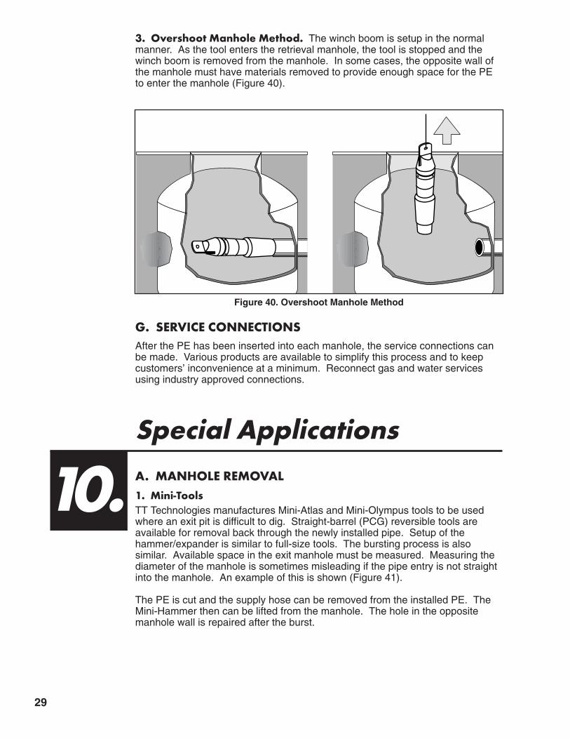
3. Overshoot Manhole Method. The winch boom is setup in the normalmanner. As the tool enters the retrieval manhole, the tool is stopped and thewinch boom is removed from the manhole. In some cases, the opposite wall ofthe manhole must have materials removed to provide enough space for the PEto enter the manhole (Figure 40).
G. SERVICE CONNECTIONSAfter the PE has been inserted into each manhole, the service connections canbe made. Various products are available to simplify this process and to keepcustomers’ inconvenience at a minimum. Reconnect gas and water servicesusing industry approved connections.
Special Applications A. MANHOLE REMOVAL1. Mini-ToolsTT Technologies manufactures Mini-Atlas and Mini-Olympus tools to be usedwhere an exit pit is difficult to dig. Straight-barrel (PCG) reversible tools areavailable for removal back through the newly installed pipe. Setup of thehammer/expander is similar to full-size tools. The bursting process is alsosimilar. Available space in the exit manhole must be measured. Measuring thediameter of the manhole is sometimes misleading if the pipe entry is not straightinto the manhole. An example of this is shown (Figure 41).
The PE is cut and the supply hose can be removed from the installed PE. TheMini-Hammer then can be lifted from the manhole. The hole in the oppositemanhole wall is repaired after the burst.
10.
Figure 40. Overshoot Manhole Method

30
In addition to the above usage, the Mini-Hammers can be used in service burststo reduce the pit dimensions. Information on specific jobs can be given to TTProduct Specialists for evaluation and feasibility.
B. WINDOWING* - EXIT MANHOLE -10” AND SMALLER PETT Technologies has a method of tool removal which uses a pilot shaft out of theexit manhole.
Locate utilities before your dig. GRUNDOCRACK tool contact with power cable cancause injury or death.
This process begins by preparing the opposite wall of the manhole. Create ahole larger than the expander diameter above the outflow pipe. Be careful toensure that the outflow pipe will not be damaged as the tool is removed. Oncethe manhole wall opening is complete, create a bore using a 2¹⁄₂ - 3"GRUNDOMAT Piercing Tool from inside the manhole up to the surface at a20-25 degree angle. Once the pilot hole is in place, open the hole to a usable diameter using a larger tool and expander (Mini-Atlas, Mini-Olympus).
Perform the burst with the normal setup, and once the hammer/expander entersthe exit manhole, remove the winch boom, move the winch to the ground levelwindow shaft exit, and secure it. Place the winch rope down the window shaft,and connect it to the hammer’s pulling eye. Use the winch to pull the hammerassembly into the window shaft until the new PE is in the manhole. Disconnectthe PE from the hammer assembly, and with the air still applied, pull the toolthrough the window shaft to the surface. Shut off the air pressure, and removethe air hoses and shock valve from either direction (Figures 42–44), forillustrations of windowing from the exit manhole.
X
Less than
X
Figure 41. Measuring Diameter of Manhole
DANGER
* Patent Pending

31
GRUNDOWINCH®
NewPE Pipe
EntrancePit
GRUNDOCRACK®
Pneumatic BurstingTool
Figure 42. Windowing Exit, Step 1.
GRUNDOMAT®
Pneumatic Piercing Tool
GRUNDOCRACK®
Pneumatic Bursting Tool
Pilot Bore
Air Compressor
New PE Pipe
EntrancePit
Figure 43. Windowing Exit, Step 2.
New PE Pipe
GRUNDOCRACK®
Pneumatic BurstingTool
GRUNDOWINCH®
EntrancePit
Figure 44. Windowing Exit, Step 3.

32
GRUNDOMAT®
Pneumatic Piercing Tool
Pilot Bore
Air Compressor
Figure 45. Windowing Entrance, Step 1.
EnlargedPilot Bore
GRUNDOWINCH®GRUNDOCRACK®
Pneumatic BurstingTool
Air Hose
Figure 46. Windowing Entrance, Step 2.
* Patent Pending
C. WINDOWING* - ENTRANCE MANHOLEUse a similar process to start the hammer/expander/PE assembly into the hostpipe.
The angle of the window shaft out of the manhole may have to be smaller toallow the hammer assembly to bend into the host pipe and not dive out. Theconstruction of the shaft is similar, but the amount of material removed above theoutflow pipe may be enlarged to allow room for the PE to bend.
The two procedures can be used in combination to provide a trenchless PEinstallation. Detailed procedures are available from TT Technologies, Inc. Inaddition, windowing can be used in a slip-lining operation from the entrancemanhole (Figures 45–49). Windows can be used on both ends of the job site ifneeded.

33
NewPE Pipe
GRUNDOWINCH®
GRUNDOCRACK®
Pneumatic BurstingTool
Figure 47. Windowing Entrance, Step 3.
GRUNDOWINCHBoom
New PE Pipe
GRUNDOCRACK®
Pneumatic BurstingTool
Figure 49. Windowing Entrance, Step 5.
GRUNDOWINCHGRUNDOCRACK®
Pneumatic BurstingTool
NewPE Pipe
Figure 48. Windowing Entrance, Step 4.

34
��������������������������������
®
Figure 50. Straight Barrel Removal, Step 1.
��������������������������������
®
Figure 51. Straight Barrel Removal, Step 2.
D. REVERSE REMOVAL WITH PCG "STRAIGHT BARREL TOOLS"GRUNDOCRACK PCG tools can be reversed automatically with a quick throw ofa lever on the in-line lubricator. Once the expander is disconnected, the tool isreversed and removed back through the newly installed PE Pipe. Reverseshould be used at only 25% power. This method can save time and expense ofexit pit removal. Ideal for same-size bursting applications including 6" to 6", 8" to8", 10" to 10", 12" to 12", 14" to 14", 16" to 16", 18" to 18", 20" to 20", ormaximum one-size upsize depending on front expander configuration(Figures 50–53).
��������������������������������
®
Figure 52. Straight Barrel Removal, Step 3.

35
��������
Figure 54. Lateral Pipe Replacement
��������������������������������
®
Figure 53. Straight Barrel Removal, Step 4.
E. LATERAL PIPE REPLACEMENTThe GRUNDOCRACK Mini-Atlas and the 2-ton GRUNDOWINCH are ideallysuited for 4" and 6" lateral pipe replacements. Nearly any type of host pipe canbe burst and replaced with HDPE or PVC pipe. Typical bursts may run from10-100' in length. By teaming up the Mini-Atlas with the 2-ton GRUNDOWINCHyou create an effective, portable and economical way to replace laterals(Figure 54).
Note: Reversible pipe bursting tools often cannot do as long a burst as the rear expander production tools. Revesibles must be smaller than new pipe being pulled in in order to be reversible. Smaller tools mean less power.

36
11.AppendicesA. GRUNDOCRACK APPLICATION CHECKLIST:Questions concerning the old pipe:1. Quality of the old pipe: ______________________________________________________
A.) Is any of the pipe run collapsed? ____________________________________________2. Diameter of old pipes: ______________OD ____________ID3. Material of old pipe: ______Clay ______Cast Iron ____Concrete ______PVC______Other4. Type of old pipe: ______________Pressure Pipe ____________Sewage Pipe5. Number of required house connections:__________________________________________6. Cover Depth ______________________________________________________________7. Has the pipe been inspected with a camera? ________ Yes __________No
A.) What is the result of the inspection: __________________________________________B.) If so has a recording been made:____________________________________________C.) Is copy of the recording available: ______________Yes __________No
8. Has the pipe collapsed? __________Yes__________NoA.) If yes, is there enough room to pass a steel cable through the pipe? ____Yes ____No
9. What sort of bed is the pipe laying on? __________________________________________10. Has the pipe settled in the ground? ________Yes ______No11. Are the pipe joints broken or misaligned? ______Yes ______No12. What is the average length of run to be replaced? ________________________________13. What is the longest length of run to be replaced? ________________________________14. What is the total footage of the run to be replaced? ______________________________15. Are tree roots to be expected because of adjacent trees? ________Yes ______No16. Is this a one-time site only? ______Yes ______No17. What is the customer's main field of application?__________________________________18. Is the existing pipe concrete encased? ______Yes ____No
A.) Is the existing pipe sitting on any footings? ____Yes ____NoB.) Are they anchored in? ______Yes ____No
19. Are there any bends in the old line between manholes? ____Yes ____NoA.) If yes explain: __________________________________________________________
20. Does the old line have any voids, holes or missing sections? ______Yes ______NoA.) If yes explain: __________________________________________________________
21. What is the ovality of the existing line: __________________________________________22. Has the old line been relined, slip-lined or rehabbed before? ____Yes ______No23. Is the existing pipe bedding supportive of a new pipeline? ______Yes ______No24. Is there a possible environmental hazard? ______Yes______No
A.) If yes explain: __________________________________________________________25. Is the area considered a wetland? ______Yes______No26. Is well pointing needed? ______Yes ______No
Questions concerning the new pipe:1. Quality of the new pipe: ______________________________________________________2. Diameter of the new pipe: ________OD ________ID3. Type of new pipe to be installed: ______________________________________________4. Type of pipe connections: ____________________________________________________5. What is the largest outside diameter of these connections: __________________________6. Length of starting pit: ________________________________________________________7. Length of exit pit: __________________________________________________________8. Capacity and type of compressor available________cubic ft/min9. Is capstan winch available? ______Yes ______No
Questions Regarding the Job:1. Do the conditions warrant a trenchless method? ______Yes______No
A.) If yes explain: __________________________________________________________B.) Does the job require urgency for completion? ______Yes______No
Date: ____________Completed By: ____________________________________________

37
B. WELDING PROCEDURE TO INSTALL CUTTING BLADES TOEXPANDER
1. Purchase hardened wear-resistant cutting blades from TT Technologies.2. Clean front face of pipe bursting expander.3. Three or four cutting blades may be used.4. Preheat front face of pipe bursting expander (400 degrees).5. Use low hydrogen welding rod (E7018 welding rod) to attach cutting blades to
bursting face.
C. HARD SURFACE PROCEDURE(MAINTENANCE OF EXPANDERS)
1. Clean front face of pipe bursting expander.2. Preheat area to be hardsurfaced (400 degrees).3. Weld in a cross hatch pattern in the area needing hardsurfacing.

38
D. SHOCK VALVE CLEANING AND DISASSEMBLY
1. Casing 6. Seal with O-Ring2. Front Casing 7. Exhaust Ring3. Piston 8. O-Ring4. Spring 9. Casing End5. Seal with O-Ring
Tool must be in proper working condition to realize maximum operating effectiveness.
1. Clamp the shock valve in a soft claw vice.2. Quickly pre-heat the threads of the front of the casing to approximately 100° C
using a gas burner. The correct temperature can be checked by using conventional colored chalk or crayons.
3. Release the front casing (Item 2) with a C-spanner and a hammer. Unscrewthe front casing by hand.
4. Pull out piston (Item 3) and spring (Item 4).5. Release the remaining part of the casing, turn it, and clamp it again.6. Quickly pre-heat the threads of the casing end (Item 9) and release it using
C-spanner and a hammer. Unscrew the casing end by hand.7. Remove the exhaust ring (Item 7).8. Carefully clean all the components. When using degreasing solvents keep to
the appropriate regulations.9. Check whether the seals (Items 5, 6, and 8) are worn out and replace if
necessary.10. Clamp the casing (Item 1) into a soft jaw vice.11. Push on the exhaust ring (Item 7) onto the casing end.12. Apply Loctite PST 567 onto the last threads of the casing end and screw it
onto the casing by hand.13. Secure the casing end by applying a few hammer blows onto the C-spanner.14. Turn the already assembled part of the casing and clamp it again.15. Slide the spring (Item 4) and the piston (Item 3) onto the casing (Item 1).16. Apply Loctite PST 567 onto the last threads of the front casing and screw it
onto the casing by hand.17. Secure the front casing by applying a few hammer blows onto the C-spanner.18. The couplings for the connection to the flat-lay hose can remain in the casing
end and front casing during the cleaning process.19. The shock valve can now be used.20. After each use, clean the shock valve with diesel fuel, GRUNDO-OIL, air tool
oil, or kerosene, install protective caps, and store it in a clean, secure place.This will help prevent components from rusting during storage.
�������������
���������������������������
9 8 7 1 4 3 6 5 2
Figure 55. Construction of Shock Valve

E. NON-TT SUPPLIED EQUIPMENT FOR PIPE BURSTING JOBS
1. Enough labor for the job - TT offers technical support services only.2. Rubber tired backhoe - necessary to lift hammer, pull PE pipe, install winch
boom in manhole, etc.3. Proper shoring equipment to make all pits safe.4. Adequate bypass equipment - reversible jobs require extensive manhole
preparation; the job cannot be accomplished with sewage running through themanhole.
5. Trash pumps to handle ground water and lateral seepage.6. A method to pull rope into PE pipe and host pipe to install air hoses and winch
rope. A duct rodder will work on PE trains up to 300 feet, but does not workwell in large diameter PE (14"+).
7. Two air hose spanner wrenches for flat-lay hose connections - using pipewrenches will damage the rubber gaskets in the air supply hoses ifover-tightened.
8. At least 500 feet of high quality 5/8" or larger rope - any smaller diameter willnot last as long or break.
9. Drill, drill bits, hex sockets, and necessary hand tools, including a 25' tape,sledge hammer, digging bar and straps and chains for lifting.
10. Lumber for winch boom standoff, 4"x4", 6"x6". More sizes will be needed if doing a static burst. Plywood and steel plates may also be needed.
11. Hand-held radios - 3 good quality (Nextel cell phones don't work).12. Chain saw, sawzall, etc to cut PE pipe.13. Manhole safety equipment, including testers, ventilators, etc.14. Air compressor sized to the hammer being used, and an additional
compressor for manhole work - including hose and jackhammers.
F. STANDARD DIPS* DIMENSIONS & WORKING PRESSURERATINGS (WPR)
G. MINIMUM BEND RADIUS CALCULATIONS FOR HDPE PIPE
STANDARD DIPS* DIMENSIONS & WORKING PRESSURE RATINGS (WPR)**
SizeDR 21
WPR @ 80 psiDR 17
WPR @ 100 psiDR 13.5
WPR @ 130 psiDR 11
WPR @ 160 psiNom.Size
"DIPS"
ODSize(in)
Avg.ID
(in)
Min.Wall(in)
Weight(lbs/ft)
Avg.ID
(in)
Min.Wall(in)
Weight(lbs/ft)
Avg.ID
(in)
Min.Wall(in)
Weight(lbs/ft)
Avg.ID
(in)
Min.Wall(in)
Weight(lbs/ft)
4" 4.80 4.323 0.229 1.44 4.216 0.282 1.75 4.070 0.356 2.17 3.909 0.436 2.616" 6.90 6.215 0.329 2.97 6.060 0.406 3.62 5.851 0.511 4.48 5.620 0.627 5.398" 9.05 8.151 0.431 5.11 7.950 0.532 6.23 7.675 0.670 7.71 7.375 0.823 9.2810" 11.10 10.000 0.529 7.68 9.750 0.653 9.37 9.413 0.822 11.60 9.041 1.009 13.9512" 13.20 11.890 0.629 10.86 11.600 0.776 13.25 11.190 0.978 16.40 10.750 1.200 19.7316" 17.40 15.675 0.829 18.87 15.285 1.024 23.02 14.750 1.289 28.49 14.170 1.582 34.2918" 19.50 17.560 0.929 23.70 17.125 1.147 28.92 16.536 1.444 35.78 15.925 1.773 43.0720" 21.60 19.455 1.029 29.08 18.975 1.271 35.48 18.315 1.600 43.91 17.590 1.964 52.8424" 25.80 23.238 1.229 41.05 22.668 1.518 50.62 21.880 1.911 62.64 21.014 2.345 75.39
* Ductile-Iron OD Pipe Sizing** Per AWWA C906, the working pressure rating equals the pressure class, with an allowance included in the WPR for pressure surge.
MMIINNIIMMUUMM AALLLLOOWWAABBLLEE BBEENNDD RRAADDIIUUSS ffoorr HHDDPPEE PPIIPPEE @@ 7733°°FFSDR 7 9 11 13.5 15.5 17 19 21 26 32.5
Minimum BendRadius, R > 20 x OD > 20 x OD > 25 x OD > 25 x OD > 27 x OD > 27 x OD > 27 x OD > 28 x OD > 35 x OD > 40 x OD
a
HDPE pipe can be bent to a minimum radius between 20 to 40 times the pipe diameter.
EXAMPLE: For 24" SDR 21 pipe, the minimum bend radius (Ra) is calculated as shown:Where: Ra = radius of pipe curvature (in.) and OD = the outside diameter of the pipe (in.)
Ra > 28 x OD" Ra > 28 x 24" Ra > 672"Thus: The radius of the circular sector (bend) must be greater than 672" (56 ft.)39

H. HDPE PIPE SIZE & DIMENSION CHARTS 4" (4.500 OD)
HDPE PipeSize WPR
Avg. ID(in)
Min. Wall(in)
Weight(lbs/ft)
SDR 7 267 psi 3.214 .643 3.39
SDR 9 200 psi 3.500 .500 2.74
SDR 11* 160 psi 3.682 .409 2.29
SDR 13.5 128 psi 3.834 .333 1.90
SDR 15.5* 110 psi 3.920 .290 1.68
SDR 17* 100 psi 3.970 .265 1.54
SDR 19 89 psi 4.026 .237 1.39
SDR 21 80 psi 4.072 .214 1.26
SDR 26* 64 psi 4.154 .173 1.03
SDR 32.5 51 psi 4.224 .138 0.83
6" (6.625 OD)
HDPE PipeSize WPR
Avg. ID(in)
Min. Wall(in)
Weight(lbs/ft)
SDR 7 267 psi 4.733 .946 7.33
SDR 9 200 psi 5.153 .736 5.93
SDR 11* 160 psi 5.421 .602 4.97
SDR 13.5 128 psi 5.643 .491 4.13
SDR 15.5 110 psi 5.771 .427 3.63
SDR 17* 100 psi 5.845 .390 3.34
SDR 19 89 psi 5.927 .349 3.01
SDR 21* 80 psi 5.995 .315 2.73
SDR 26* 64 psi 6.115 .255 2.23
SDR 32.5* 51 psi 6.217 .204 1.80
7" (7.125 OD)
HDPE PipeSize WPR
Avg. ID(in)
Min. Wall(in)
Weight(lbs/ft)
SDR 7 267 psi 5.089 1.018 8.49
SDR 9 200 psi 5.541 .792 6.86
SDR 11 160 psi 5.829 .648 5.75
SDR 13.5 128 psi 6.069 .528 4.78
SDR 15.5 110 psi 6.205 .460 4.21
SDR 17 100 psi 6.287 .419 3.86
SDR 19 89 psi 6.375 .375 3.48
SDR 21 80 psi 6.445 .340 3.16
SDR 26* 64 psi 6.577 .274 2.58
SDR 32.5 51 psi 6.685 .220 2.08
* Denotes Standard Sizes
8" (8.625 OD)
HDPE PipeSize WPR
Avg. ID(in)
Min. Wall(in)
Weight(lbs/ft)
SDR 7 267 psi 6.161 1.232 12.43
SDR 9 200 psi 6.709 .958 10.05
SDR 11* 160 psi 7.057 .784 8.42
SDR 13.5 128 psi 7.347 .639 7.00
SDR 15.5 110 psi 7.513 .556 6.16
SDR 17* 100 psi 7.611 .507 5.65
SDR 19 89 psi 7.717 .454 5.10
SDR 21* 80 psi 7.803 .411 4.64
SDR 26* 64 psi 7.961 .332 3.79
SDR 32.5* 51 psi 8.095 .265 3.05
40

41
10" (10.750 OD)
HDPE PipeSize WPR
Avg. ID(in)
Min. Wall(in)
Weight(lbs/ft)
SDR 7 267 psi 7.678 1.536 19.32
SDR 9 200 psi 8.362 1.194 15.61
SDR 11* 160 psi 8.796 .977 13.09
SDR 13.5 128 psi 9.158 .796 10.87
SDR 15.5 110 psi 9.362 .694 9.58
SDR 17* 100 psi 9.486 .632 8.78
SDR 19 89 psi 9.618 .566 7.92
SDR 21* 80 psi 9.726 .512 7.21
SDR 26* 64 psi 9.924 .413 5.87
SDR 32.5* 51 psi 10.088 .331 4.75
12" (12.750 OD)
HDPE PipeSize WPR
Avg. ID(in)
Min. Wall(in)
Weight(lbs/ft)
SDR 7 267 psi 9.108 1.821 27.16
SDR 9 200 psi 9.916 1.417 21.97
SDR 11* 160 psi 10.432 1.159 18.41
SDR 13.5 128 psi 10.862 .944 15.29
SDR 15.5* 110 psi 11.104 .823 13.48
SDR 17* 100 psi 11.250 .750 12.36
SDR 19 89 psi 11.408 .671 11.14
SDR 21* 80 psi 11.536 .607 10.13
SDR 26* 64 psi 11.770 .490 8.26
SDR 32.5* 51 psi 11.966 .392 6.67
14.000 OD
HDPE PipeSize WPR
Avg. ID(in)
Min. Wall(in)
Weight(lbs/ft)
SDR 7 267 psi 10.000 2.000 32.76
SDR 9 200 psi 10.888 1.556 26.50
SDR 11* 160 psi 11.454 1.273 22.20
SDR 13.5 128 psi 11.926 1.037 18.44
SDR 15.5 110 psi 12.194 .903 16.24
SDR 17* 100 psi 12.352 .824 14.91
SDR 19 89 psi 12.526 .737 13.43
SDR 21 80 psi 12.666 .667 12.22
SDR 26* 64 psi 12.924 .538 9.96
SDR 32.5 51 psi 13.138 .431 8.05
16.000 OD
HDPE PipeSize WPR
Avg. ID(in)
Min. Wall(in)
Weight(lbs/ft)
SDR 9 200 psi 12.444 1.778 34.60
SDR 11* 160 psi 13.090 1.455 29.00
SDR 13.5 128 psi 13.630 1.185 24.09
SDR 15.5 110 psi 13.936 1.032 21.21
SDR 17* 100 psi 14.118 .941 19.46
SDR 19 89 psi 14.316 .842 17.54
SDR 21* 80 psi 14.476 .762 15.96
SDR 26* 64 psi 14.770 .615 13.01
SDR 32.5 51 psi 15.016 .492 10.50
* Denotes Standard Sizes

42
18.000 OD
HDPE PipeSize WPR
Avg. ID(in)
Min. Wall(in)
Weight(lbs/ft)
SDR 9 200 psi 14.000 2.000 43.79
SDR 11* 160 psi 14.728 1.636 36.69
SDR 13.5 128 psi 15.334 1.333 30.48
SDR 15.5* 110 psi 15.678 1.161 26.84
SDR 17* 100 psi 15.882 1.059 24.64
SDR 19 89 psi 16.106 .947 22.19
SDR 21 80 psi 16.286 .857 20.19
SDR 26* 64 psi 16.616 .692 16.47
SDR 32.5 51 psi 16.892 .554 13.30
20.000 OD
HDPE PipeSize WPR
Avg. ID(in)
Min. Wall(in)
Weight(lbs/ft)
SDR 9 200 psi 15.556 2.222 54.05
SDR 11* 160 psi 16.364 1.818 45.30
SDR 13.5 128 psi 17.038 1.481 37.63
SDR 15.5 110 psi 17.420 1.290 33.14
SDR 17 100 psi 17.648 1.176 30.41
SDR 19 89 psi 17.894 1.053 27.42
SDR 21 80 psi 18.096 .952 24.93
SDR 26* 64 psi 18.462 .769 20.34
SDR 32.5* 51 psi 18.770 .615 16.41
22.000 OD
HDPE PipeSize WPR
Avg. ID(in)
Min. Wall(in)
Weight(lbs/ft)
SDR 9 200 psi 17.112 2.444 65.40
SDR 11* 160 psi 18.000 2.000 54.82
SDR 13.5 128 psi 18.740 1.630 45.56
SDR 15.5 110 psi 19.162 1.419 40.10
SDR 17 100 psi 19.412 1.294 36.80
SDR 19 89 psi 19.684 1.158 33.16
SDR 21 80 psi 19.904 1.048 30.18
SDR 26* 64 psi 20.308 .846 24.61
SDR 32.5* 51 psi 20.646 .677 19.86
24.000 OD
HDPE PipeSize WPR
Avg. ID(in)
Min. Wall(in)
Weight(lbs/ft)
SDR 9 200 psi 18.666 2.667 77.85
SDR 11* 160 psi 19.636 2.182 65.24
SDR 13.5 128 psi 20.444 1.778 54.21
SDR 15.5 110 psi 20.904 1.548 47.72
SDR 17* 100 psi 21.176 1.412 43.81
SDR 19 89 psi 21.474 1.263 39.46
SDR 21* 80 psi 21.714 1.143 35.91
SDR 26* 64 psi 22.154 .923 29.30
SDR 32.5* 51 psi 22.524 .738 23.62
* Denotes Standard Sizes

43
26.000 OD
HDPE PipeSize WPR
Avg. ID(in)
Min. Wall(in)
Weight(lbs/ft)
SDR 11 160 psi 21.272 2.364 76.57
SDR 13.5 128 psi 22.148 1.926 63.62
SDR 15.5 110 psi 22.646 1.677 56.00
SDR 17 100 psi 22.942 1.529 51.39
SDR 19 89 psi 23.264 1.368 46.30
SDR 21 80 psi 23.524 1.238 42.14
SDR 26 64 psi 24.000 1.000 34.39
SDR 32.5* 51 psi 24.400 .800 27.74
28.000 OD
HDPE PipeSize WPR
Avg. ID(in)
Min. Wall(in)
Weight(lbs/ft)
SDR 11 160 psi 22.910 2.545 88.78
SDR 13.5 128 psi 23.852 2.074 73.78
SDR 15.5 110 psi 24.388 1.806 64.95
SDR 17* 100 psi 24.706 1.647 59.62
SDR 19 89 psi 25.052 1.474 53.73
SDR 21 80 psi 25.334 1.333 48.86
SDR 26 64 psi 25.846 1.077 39.88
SDR 32.5* 51 psi 26.276 .862 32.19
* Denotes Standard Sizes
30.000 OD
HDPE PipeSize WPR
Avg. ID(in)
Min. Wall(in)
Weight(lbs/ft)
SDR 11 160 psi 24.546 2.727 101.92
SDR 13.5 128 psi 25.556 2.222 84.69
SDR 15.5 110 psi 26.130 1.935 74.56
SDR 17 100 psi 26.470 1.765 68.45
SDR 19 89 psi 26.842 1.579 61.67
SDR 21* 80 psi 27.142 1.429 56.12
SDR 26 64 psi 27.692 1.154 45.78
SDR 32.5* 51 psi 28.154 .923 36.93
32.000 OD
HDPE PipeSize WPR
Avg. ID(in)
Min. Wall(in)
Weight(lbs/ft)
SDR 13.5 128 psi 27.260 2.370 96.35
SDR 15.5 110 psi 27.870 2.065 84.87
SDR 17 100 psi 28.236 1.882 77.86
SDR 19 89 psi 28.632 1.684 70.15
SDR 21 80 psi 28.952 1.524 63.84
SDR 26 64 psi 29.538 1.231 52.10
SDR 32.5* 51 psi 30.030 .985 42.04
34.000 OD
HDPE PipeSize WPR
Avg. ID(in)
Min. Wall(in)
Weight(lbs/ft)
SDR 13.5 128 psi 28.962 2.519 108.81
SDR 15.5 110 psi 29.612 2.194 95.81
SDR 17 100 psi 30.000 2.000 87.91
SDR 19 89 psi 30.422 1.789 79.17
SDR 21 80 psi 30.762 1.619 72.06
SDR 26 64 psi 31.384 1.308 58.81
SDR 32.5 51 psi 31.908 1.046 47.43

44
36.000 OD
HDPE PipeSize WPR
Avg. ID(in)
Min. Wall(in)
Weight(lbs/ft)
SDR 13.5 128 psi 30.666 2.667 121.98
SDR 15.5 110 psi 31.354 2.323 107.41
SDR 17 100 psi 31.764 2.118 98.57
SDR 19 89 psi 32.210 1.895 88.81
SDR 21* 80 psi 32.572 1.714 80.78
SDR 26* 64 psi 33.230 1.385 65.94
SDR 32.5* 51 psi 33.784 1.108 53.20
1000 mm (39.370 OD)
HDPE PipeSize WPR
Avg. ID(in)
Min. Wall(in)
Weight(lbs/ft)
SDR 17 100 psi 34.738 2.316 117.88
SDR 19 89 psi 35.226 2.072 106.18
SDR 21 80 psi 35.620 1.875 96.64
SDR 26 64 psi 36.342 1.514 78.83
SDR 32.5 51 psi 36.948 1.211 63.69
42.000 OD
HDPE PipeSize WPR
Avg. ID(in)
Min. Wall(in)
Weight(lbs/ft)
SDR 17 100 psi 37.058 2.471 134.16
SDR 19 89 psi 37.578 2.211 120.89
SDR 21 80 psi 38.000 2.000 109.97
SDR 26* 64 psi 38.770 1.615 89.71
SDR 32.5* 51 psi 39.416 1.292 72.37
1200 mm (47.244 OD)
HDPE PipeSize WPR
Avg. ID(in)
Min. Wall(in)
Weight(lbs/ft)
SDR 19 89 psi 42.270 2.487 152.94
SDR 21 80 psi 42.744 2.250 139.16
SDR 26* 64 psi 43.610 1.817 113.53
SDR 32.5* 51 psi 44.336 1.454 91.62
54.000 OD
HDPE PipeSize WPR
Avg. ID(in)
Min. Wall(in)
Weight(lbs/ft)
SDR 26* 64 psi 49.846 2.077 148.33
SDR 32.5* 51 psi 50.676 1.662 119.70
* Denotes Standard Sizes

45
I. PARTS LIST FOR PCF 130
Item No Description Qty Part Number
1-2 Machine body with protection ring (without cable) 1 PCF 1300154
2 Protection ring 1 EPC 1301087
3 Piston 1 G-Z 1305141
4 Piston slide tapes (set) 1 GRS 1305130
5 Piston seal 1 GRU 1305160
6-8 Control tube with elastic block and seal ring 1 AF 1300159
6 Control tube 1 AF 1300160
7 Control stud seal 1 A 1300107
8 Elastic block 1 AF 1300165
9 Support ring 1 AF 1300166
10 Segment ring 1 AF 1300167
w.o. pic. Rubber buffer 1 AF 1300180
11 Lock nut 1 DF 0950121
12 Lock pin (set) 1 PAA 1300110
13 Steel cable with thimble 1 YY 061935
15-20 Connection air hose, complete 1 PCF 1300170
15 Nozzle with spigot nut 1 YY 191496
16 Swaging socket 50x2,5x60 1 GRU 2002460
16A Swaging socket with claw 1 YY 192243
17 Connection air hose (without couplings) 1 GRU 2002440
18 Female coupling ND 32 for swaging 1 GRU 2006680
19 Seal for quick-coupling socket DN 32 1 G-E 1452340
20 Sealing cap for quick-coupling DN 32 1 GRU 2006641
— Seals, (complete set) 1 PCF 1300104
1-20 Grundocrack PCF 130(Blade head, table and protection ring) 1 PCF 1300007

46
J. PARTS LIST FOR PCF 145
Item No Description Qty Part Number
1-2 Machine body with protection ring (without cable) 1 PCF 1450156
2 Protection ring 1 EPC 1451087
3 Piston 1 G-E 1455141
4 Piston slide tapes (set) 1 G-E 1455130
5 Piston seal 1 G-E 1455160
6-8 Control tube with elastic block and seal ring 1 TF 1450159
6 Control tube 1 TF 1450160
7 Control stud seal 1 T 1450107
8 Elastic block 1 TF 1450165
9 Support ring 1 TF 1450166
10 Segment ring 1 TF 1450167
11 Lock nut with 55x1/6" knurled thread 1 G 2600221
12 Lock pin (set) 1 PAA 1300110
13 Steel cable with thimble 1 YY 061935
15-17, 19-23 Connection air hose, complete 1 PCF 1450170
w.o. pic. Lock screw with 55x1/6" knurled thread 1 G 2600245
15 Knurled thread coupling with 55x1/6" knurledthread for swaging 1 H 2200211
16 Swaging socket 67x5x80 mm 2 YY 191698
17 Connection air hose (without couplings) 1 PCF 1450160
19 Seal for quick-coupling socket DN 32 1 G-E 1452340
20 Sealing cap for quick-coupling DN 32 1 GRU 2006641
22 Hose socket 1 1/2" with 1" internal thread 1 YY 071779
23 Female coupling with 1" outer thread 1 GRU 2002650
— Seals, (complete set) 1 PCF 1450104
1-23 Grundocrack PCF 145(Blade head, table and protection ring) 1 PCF 1450007

47
K. PARTS LIST FOR PCF 180
Item No Description Qty Part Number
1-2 Machine body with protection ring (without cable) 1 PCF 1800156
2 Protection ring 1 EPC 1801087
3 Piston 1 O 1800103
4 Piston slide tapes (set) 1 O 1800104
5 Piston seal 1 G-E 1805160
6-8 Control tube with elastic block and seal ring 1 OF 1800159
6 Control tube 1 OF 1800160
7 Control stud seal 1 O 1800107
8 Elastic block 1 OF 1800165
9 Support ring 1 OF 1800166
10 Segment ring 1 OF 1800167
11 Locking nut with 75x1/6" knurled thread 1 G 4500113
12 Lock pin (set) 1 PCF 2200110
13 Steel cable with thimble 1 YY 152135
15-17, 19-23 Connection air hose, complete 1 PCF 1800170
w.o. pic. Lock screw with 75x1/6" knurled thread 1 G 4500245
15 Knurled thread coupling with 75x1/6" knurledthread for swaging 1 G 2600114
16 Swaging socket for hose 2" 2 YY 192098
17 Connection air hose (without couplings) 1 PCF 1800160
19 Seal for quick-coupling socket DN 32 1 G-E 1452340
20 Sealing cap for quick-coupling DN 32 1 GRU 2006641
22 Hose socket with 1" internal thread 1 YY 151754
23 Female coupling with 1" outer thread 1 GRU 2002650
— Seals, (complete set) 1 PCF 1800104
1-23 Grundocrack PCF 180(Blade head, table and protection ring) 1 PCF 1800007

48
L. PARTS LIST FOR PCF 220
Item No Description Qty Part Number
1-2 Machine body with protection ring (without cable) 1 PCF 2200156
2 Protection ring 1 YY 161049
3 Piston 1 H 2200103
4 Piston slide tapes (set) 1 H 2200104
5 Piston seal 1 H 2200105
6-8 Control tube with elastic block and seal ring 1 HF 2200159
6 Control tube 1 HF 2200160
7 Control stud seal 1 H 2200107
8 Elastic block 1 HF 2200165
9 Support ring 1 HF 2200166
10 Segment ring 1 HF 2200167
11 Lock nut with 75x1/6" knurled thread 1 G 4500113
12 Lock pin (set) 1 PCF 1800110
13 Steel cable with thimble 1 YY 152135
24-30 1 meter compressed air hose 2" knurled thread75x1/6" internal thread / 55x1/6" external thread 1 GF 4500384
w.o. pic. Lock screw with 75x1/6" knurled thread 1 G 4500245
24 Knurled thread coupling with 75x1/6" knurledthread for swaging 1 G 2600114
24A Sleeve with hexagon nut with 75x1/5" knurled thread 1 YY 192315
25 Swaging socket for hose 2" 2 YY 192098
26 Connection air hose (without couplings) 1 PCF 1800160
27 Connection nipple 75x1/6" - 2" 1 G 2600214
28 Sleeve 2" - 1 1/2" 1 H 2200222
29 Connection nipple 55x1/6" - 1 1/2" 1 H 2200212
30 Locking nut with 55x1/6" knurled thread 1 G 2600221
— Seals, (complete set) 1 H 2200111
1-30 Grundocrack PCF 220(Blade head, table and protection ring) 1 PCF 2200007

49
M. PARTS LIST FOR 130 MINI-ATLAS
Item No Description Qty Part Number
4 Machine body with knife head and RK reception 1 AM 1300153
10 Piston 1 AM 1300103
15 Piston slide tapes (set) 1 GRS 1305130
20 Piston seal 1 GRU 1305160
25 Control tube for reverse run control 1 AM 1300156
30 Control stud seal 1 A 1300107
35 Casing end with cable connection, without cable 1 AM 1300118
40 Elastic block 1 AM 1300122
45 Adjusting nut for reverse run control 1 AM 1300121
50 Stop nut for reverse run control 1 AM 1300120
55 Segment ring for reverse run control 1 AM 1300125
60 Support ring for reverse run control 1 AM 1300128
65 Pin set (set=2 pieces) 1 AM 1300123
75-100 Connection air hose, complete, 0.3 m long 1 AM 1300160
75 Nozzle DN 25 with ring and spigot nut 1 AM 1300161
100 Sealing cap for quick-coupling DN 25 1 G-E 0902390
15, 20, 30 Seals, (complete set) 1 AM 1300115
4-100 Mini-Atlas 130 with slotted head,10 degrees receptionand 1' whip hose 1 AM 1300004

50
N. PARTS LIST FOR 180 MINI-OLYMPUS
Item No Description Qty Part Number
1 Machine body with thread M 60x3 and vent plug 1 OM 1800157
w.o. pic. Seal plug, complete, for thread M 60 1 H 2200335
w.o. pic. Pulling eye (bore-D 30) M 60, complete 1 H 2200319
2 Piston 1 OM 1800103
3 Piston slide tapes (set) 1 OM 1800104
4 Piston seal 1 G-E 1805160
5 Control tube for reverse run control 1 OM 1800156
6 Control stud seal 1 O 1800107
7 Casing end 1 OM 1800125
8 Dust cap with 55x1/6" knurled thread 1 G 2600221
9 Stop ring for reverse run control 1 OM 1800119
10 Stop nut for reverse run control 1 OM 1800120
11 Adjusting nut for reverse run control 1 OM 1800121
12 Aeration block semi-shells (set=2 halves) 1 OM 1800122
13 Pin set (set=2 pieces) 1 OM 1800123
w.o. pic. Connection whip hose 7', complete without ball valve 1 G 2600223
w.o. pic. Dust plug with 55x1/6" knurled thread 2 G 2600245
w.o. pic. Ball valve 55x1/6" knurled thread on both sides with dust caps 1 H 2200242
w.o. pic. Dust cap with 55x1/6" knurled thread 2 G 2600221
no pos. Seals, (complete set) 1 OM 1800115
w.o. pic. Mini-Olympus 180 with 10 degrees reception, thread M 60x3 1 OM 1800005

51
O. PARTS LIST FOR 180 OLYMPUS
Item No Description Qty Part Number
1 Machine body (front thread M 60, plug) 1 OF 1800152
24 Seal plug, complete, for thread M 60 (from 01.96) 1 H 2200335
26 Pulling eye (bore-D 30) M 60, complete (from 01.96) 1 H 2200319
2 Piston 1 O 1800103
3 Piston slide tapes (set) 1 O 1800104
4 Piston seal 1 G-E 1805160
5-7 Control tube with elastic block and seal ring 1 OF 1800159
5 Control tube 1 OF 1800160
6 Control stud seal 1 O 1800107
7 Elastic block 1 OF 1800165
8 Support ring 1 OF 1800166
9 Segment ring 1 OF 1800167
10 Dust cap with 75x1/6" knurled thread 1 G 4500113
17 7' air hose 2", on both sides knurled thread connection 75x1/6" 1 G 4500381
18 Dust plug with 75x1/6" knurled thread 1 G 4500245
19 Ball valve 1 1/2", on one side 55x1/6",on the other side 75x1/6" knurled thread connection 1 HF 2200241
20 Dust cap with 55x1/6" knurled thread 1 G 2600221
20a Dust cap with 75x1/6" knurled thread 1 G 4500113
— Seals, (complete set) 1 O 1800109
— Grundocrack Olympus 180 F complete (front thread M 60, plug) 1 OF 1800005

52
P. PARTS LIST FOR 220 HERCULES
Item No Description Qty Part Number
1 Machine body (front thread M 60, plug) 1 HF 2200152
24 Seal plug, complete, for thread M 60 (from 01.96) 1 H 2200335
26 Pulling eye (bore-D 30) M 60, complete (from 01.96) 1 H 2200319
2 Piston 1 H 2200103
3 Piston slide tapes (set) 1 H 2200104
4 Piston seal 1 H 2200105
5-7 Control tube with elastic block and seal ring 1 HF 2200159
5 Control tube 1 HF 2200160
6 Control stud seal 1 H 2200107
7 Elastic block 1 HF 2200165
8 Support ring 1 HF 2200166
9 Segment ring 1 HF 2200167
10 Dust cap with 75x1/6" knurled thread 1 G 4500113
17 7' air hose 2", on both sides knurled thread connection 75x1/6" 1 G 4500381
18 Dust plug with 75x1/6" knurled thread 1 G 4500245
19 Ball valve 1 1/2", on one side 55x1/6",on the other side 75x1/6" knurled thread connection 1 HF 2200241
20 Dust cap with 55x1/6" knurled thread 1 G 2600221
20a Dust cap with 75x1/6" knurled thread 1 G 4500113
— Seals, (complete set) 1 H 2200111
— Grundocrack Hercules 220 F complete (front thread M 60, plug) 1 HF 2200005

53
Q. PARTS LIST FOR 260 MINI-GIGANT
Item No Description Qty Part Number
1 Machine body with bore hole, plug and RK reception 1 on request (4)
w.o. pic. Seal plug, complete, for thread M 80 1 G 2600331
w.o. pic. Pulling eye (bore-D 30) M 80, complete 1 G 2600319
w.o. pic. Lock pin (set) 1 PAA 1300110
2 Piston 1 GM 2600103
3 Piston slide tapes (set) 1 GM 2600104
4 Piston seal 1 G 2600105
5 Control tube for reverse run control 1 GM 2600156
6 Control stud seal 1 G 2600107
7 Casing end 1 GM 2600118
8 Locking nut with 75x1/6" knurled thread 1 G 4500113
9 Stop ring for reverse run control 1 GM 2600119
10 Stop nut for reverse run control 1 GM 2600120
11 Adjusting nut for reverse run control 1 GM 2600121
12 Aeration block semi-shells (set=2 halves) 1 GM 2600122
13 Pin set (set=2 pieces) 1 GM 2600123
w.o. pic Dust plug with 75x1/6" knurled thread 2 G 4500245
w.o. pic Ball valve 75x1/6" knurled thread on both sides with locking nuts 1 G 4500217
w.o. pic Dust cap with 75x1/6" knurled thread 2 G 4500113
no pos. Seals, (complete set) 1 GM 2600115
— Mini-Gigant 260 with 10 degrees reception 1 GM 2600005

54
R. PARTS LIST FOR 260 GIGANT
Item No Description Qty Part Number
1 Machine body (front thread M 90, plug) 1 GF 2600152
24 Seal plug, complete, for thread M 90 1 703249
26 Pulling eye (bore-D 30) M 90, complete 1 G 266032
2 Piston 1 G 2600103
3 Piston slide tapes (set) 1 G 2600104
4 Piston seal 1 G 2600105
5-7 Control tube with elastic block and seal ring 1 GF 2600159
5 Control tube 1 GF 2600160
6 Control stud seal 1 G 2600107
7 Elastic block 1 GF 2600165
8 Support ring 1 GF 2600166
9 Segment ring 1 GF 2600167
10 Dust cap with 75x1/6" knurled thread 1 G 4500113
17 7' connection air hose 2", on both sides knurled thread connection 75x1/6" 1 G 4500381
18 Dust plug with 75x1/6" knurled thread 1 G 4500245
19 Ball valve 75x1/6" knurled thread on both sides with locking nuts 1 G 4500217
20 Locking nut with 75x1/6" knurled thread 1 G 4500113
20a Locking nut with 75x1/6" knurled thread 1 G 4500113
— Seals, (complete set) 1 G 2600115
— Grundocrack Gigant 260 F complete (front thread M 90, plug) 1 GF 2600005

55
S. PARTS LIST FOR 350 KOLOSS
Item No Description Qty Part Number1 Machine body (front thread M 100, plug) 1 KF 3500152
24 Seal plug, complete, for thread M 100 (from 05/97) 1 GF 450033126 Pulling eye M 100 with screw (set) (from 05/97) 1 GF 4500319
w.o. pic. Screw with nut (set) for towing eye (from 05/97) 1 GF 4500323w.o. pic. Lock pin (set) (until 04/97) alternative 1 PAA 1300110w.o. pic. Lock pin (set) for towing eye (from 05/97 alternative) 1 GF 4500322
2 Piston 1 K 35001033 Piston slide tapes (set) 1 K 35001044 Piston seal 1 K 3500105
5-7 Control tube with elastic block and seal ring 1 KF 35001595 Control tube 1 KF 35001606 Control stud seal 1 K 35001077 Elastic block 1 KF 35001658 Support ring 1 KF 35001669 Segment ring 1 KF 3500167
10 Dust cap, steel 1 GF 4500168
11 Connection whip hose, complete 1 KF 350010013 Hose coupling ND 105 1 KF 350010114 Connection air hose DN 105, blank 1 G 450011116 Swaging socket for hose ND 105 1 KF 350010316 Hose clips (set) alternative 1 G 450011017 2 meter connection air hose 2", on both sides knurled
thread connection 75x1/6" 1 G 4500381
18 Dust plug with 75x1/6" knurled thread 1 G 4500245
19 Ball valve 75x1/6" knurled thread on both sides with locking nuts 1 G 4500217
20 Dust cap with 75x1/6" knurled thread 1 G 4500113
20a Dust cap with 75x1/6" knurled thread 1 G 4500113
— Seals, (complete set) 1 K 3500109— Grundocrack Koloss 350 F complete (front thread M 100, plug) 1 KF 3500005

56
T. PARTS LIST FOR 450 GOLIATH
Item No Description Qty Part Number1 Machine body (front thread M 100, plug) 1 GF 4500152
24 Seal plug, complete, for thread M 100 (from 01/96) 1 GF 450033126 Pulling eye M 100 with screw (set) (from 01/96) 1 GF 4500319
w.o. pic. Screw with nut (set) for towing eye 1 GF 4500323w.o. pic. Lock pin (set) for towing eye (alternative) 1 GF 4500322
2 Piston 1 G 45001033 Piston slide tapes (set) 1 G 45001044 Piston seal 1 G 4500105
5-7 Control tube with elastic block and seal ring 1 GF 45001595 Control tube 1 GF 45001606 Control stud seal 1 G 45001077 Elastic block 1 GF 45001658 Support ring 1 GF 45001669 Segment ring 1 GF 4500167
10 Dust cap, steel 1 GF 4500168
11 Connection whip hose 1 GF 450010013 Hose coupling ND 105 1 KF 350010114 Connection air hose DN 105, without couplings, blank hose 1 G 450011116 Swaging socket for hose ND 105 1 KF 350010316 Hose clips (set) alternative 1 G 450011017 2 meter connection air hose 2", on both sides knurled
thread connection 75x1/6" 2 G 4500381
18 Dust plug with 75x1/6" knurled thread 1 G 4500245
19 Ball valve 75x1/6" knurled thread on both sides with locking nuts 2 G 4500217
20 Dust cap with 75x1/6" knurled thread 2 G 4500113
20a Dust cap with 75x1/6" knurled thread 1 G 4500113
— Seals, (complete set) 1 G 4500109— Grundocrack Goliath 450 F complete (front thread M 100, plug) 1 GF 4500005

57
U. PARTS LIST FOR 600 TAURUS
Item No Description Qty Part Number1 Machine body (front thread M 100, plug) 1 TF 6000152
24 Seal plug, complete, for thread M 100 1 GF 450033126 Pulling eye M 100 with screw (set) 1 GF 4500319
w.o. pic. Screw with nut (set) for towing eye 1 GF 4500323w.o. pic. Lock pin (set) for towing eye (alternative) 1 GF 4500322
2 Piston 1 TF 60001033 Piston slide tapes (set) 1 TF 60001044 Piston seal 1 TF 6000105
5-7 Control tube with elastic block and seal ring 1 TF 60001595 Control tube 1 TF 60001606 Control stud seal 1 TF 60001077 Elastic block 1 TF 60001658 Support ring 1 TF 60001669 Segment ring 1 TF 6000167
10 Dust cap, steel 1 TF 6000168
13-16 Connection whip hose, complete 1 TF 600010113 Hose socket for hose coupling 2 TF 600017114 Connection air hose, blank 1 TF 600011115 Spigot nut for hose coupling 2 TF 600017016 Hose clips (pair) 2 TF 600011017 Connection T-piece, complete (incl. 1x Item 10 and 4x Item 18) 1 TF 6000102
18 Dust cap with 75x1/6" knurled thread 4 G 4500113
19 Ball valve 75x1/6" knurled thread on both sides with locking nuts 4 G 4500217— Seals, (complete set) (item 3, 4, 6) 1 TF 6000109— Grundocrack Taurus 600 F complete (front thread M 100, plug) 1 TF 6000005

58
V. PARTS LIST FOR PCG 130
Item No Description Qty Part Number1 Machine body 1 PCG 13001502 Lock pin (set) 1 PAA 13001103 Piston slide tapes (set) 1 G-E 14551304 Piston 1 G-P 13051415 Piston seal 1 G-E 1455160— Control stud with connection air hose (Items 6-22, 25-38) 1 G-V 1308000— Control stud without connection air hose (Items 6-17) 1 G-V 13080056 Segment ring 1 YY 1409207 Support ring for elastic block 1 YY 1409198 Elastic block for control sleeve 1 G-V 13080439 Stop ring 1 YY 06099810 Control sleeve seal 1 (set) 1 G-V 130807511 O-ring 41x4 mm 1 2125256412 Seal for control tube (set) 1 G-V 130807013 Cylindrical ring for control tube 1 YY 19206814 Control sleeve 1 YY 06097715 Control tube 1 YY 06099716 Control sleeve seal 2 (set) 1 G-V 130808017 Elastic block for air-operated control stud 1 G-V 1308025— Connection air hose, complete (Items 18-22, 25-38) 1 G-V 1308110— Connection air hose, (interior) (Items 18-22, 30-34, 38) 1 G-V 130815018 O-ring 32x3 mm 1 2125207119 Hose connection for connection air hose 1 YY 06097520 O-ring 49x3 mm 1 2125294321 Lock washer M 8 DIN 127 3 18012701202422 Cheese head screw M 8x30 DIN 912 3 18091251213723 Casing end with additional bore hole D 14 1 PCG 130645124 Pin set for casing end 1 PCG 1306452
w.o. pic. Pin punch with safety impact head 15x18x130x200 mm 1 220410015— Control hose (interior) (Items 25-29, 35-37) 1 G-V 180816028 O-ring 6,5x2 mm 2 2125038729 External securing ring 9x1 mm DIN 471 1 18047101000930 Swaging socket 50x2,5x60 2 GRU 200246031 Connection air hose without couplings 1 GRU 200244332 Spigot nut for connection hose DN 32 1 YY 06097833 Hose nipple for sleeve nut ND 32 1 YY 06097934 Seal 1 YY 06113236 O-ring 6,5x2 mm 1 2125038737 External securing ring 12x1 mm DIN 471 1 18047101001238 Locking nipple for spigot nut DN 32 1 YY 060988— Seals, (complete set) 1 GKV 1306325
1-38 Grundocrack PCG 130 with air-operated control stud,casing end pinned, with additional bore hole 1 PCG 1300000A

59
W. PARTS LIST FOR PCG 145
Item No Description Qty Part Number1 Machine body 1 PCG 14501502 Lock pin (set) 1 PAA 13001103 Piston slide tapes (set) 1 G-P 14551304 Piston 1 G-P 14551415 Piston seal 1 G-P 1455160— Control stud with connection air hose (Items 6-22, 25-38) 1 G-V 1458000— Control stud without connection air hose (Items 6-17) 1 G-V 14580056 Segment ring 1 YY 1409207 Support ring for elastic block 1 YY 1409198 Elastic block for control sleeve 1 G-V 16080439 Stop ring 1 YY 07091710 Control sleeve seal 1 (set) 1 G-V 145807511 O-ring 41x4 mm 1 2125256412 Seal for control tube (set) 1 G-V 130807013 Seal for control sleeve (exterior) 1 YY 19211214 Control sleeve 1 YY 07091615 Control tube 1 YY 07091516 Control sleeve seal 2 (set) 1 G-V 145808017 Elastic block for air-operated control stud 1 G-V 1458025— Connection air hose, complete (Items 18-22, 25-38) 1 G-V 1608110— Connection air hose, (interior) (Items 18-22, 30-34, 38) 1 G-V 160815018 O-ring 32x3 mm 1 2125207119 Hose connection for connection air hose 1 YY 14092320 O-ring 49x3 mm 1 2125294321 Lock washer M 8 DIN 127 3 18012701202422 Cheese head screw M 8x35 DIN 912 3 18091251213823 Casing end with additional bore hole D 14 1 PCG 145645124 Pin set for casing end 1 PCG 1456452
w.o. pic. Pin punch with safety impact head 15x18x180x300 mm 1 220410020— Control hose (interior) (Items 25-29, 35-37) 1 G-V 180816028 O-ring 6,5x2 mm 2 2125038729 External securing ring 9x1 mm DIN 471 1 18047101000930 Swaging socket 62x2,5x60 2 G-E 180246031 Connection air hose without couplings 1 G-P 180244332 Sleeve nut ND 40 1 YY 15093433 Hose nipple 1 YY 15092434 O-ring 48x3 mm 1 2125291136 O-ring 6,5x2 mm 1 2125038737 External securing ring 12x1 mm DIN 471 1 18047101001238 Locking nipple for spigot nut 1 YY 150935— Seals, (complete set) 1 PCG 1456320
1-38 Grundocrack PCG 145 with air-operated control stud,casing end pinned, with additional bore hole 1 PCG 1450000A
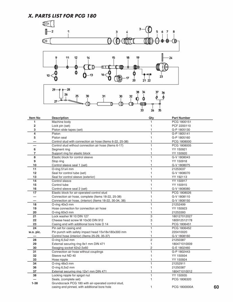
60
X. PARTS LIST FOR PCG 180
Item No Description Qty Part Number1 Machine body 1 PCG 18001512 Lock pin (set) 1 PCF 22001103 Piston slide tapes (set) 1 G-P 18051304 Piston 1 G-P 18051415 Piston seal 1 G-P 1805160— Control stud with connection air hose (Items 6-22, 25-38) 1 PCG 1808000— Control stud without connection air hose (Items 6-17) 1 PCG 18080056 Segment ring 1 YY 1509217 Support ring for elastic block 1 YY 1509208 Elastic block for control sleeve 1 G-V 18080439 Stop ring 1 YY 15091810 Control sleeve seal 1 (set) 1 G-V 180807511 O-ring 51x4 mm 1 2125303712 Seal for control tube (set) 1 G-V 180807013 Seal for control sleeve (exterior) 1 YY 19211314 Control sleeve 1 YY 15091715 Control tube 1 YY 15091516 Control sleeve seal 2 (set) 1 G-V 180808017 Elastic block for air-operated control stud 1 PCG 1808026— Connection air hose, complete (Items 18-22, 25-38) 1 G-V 1808110— Connection air hose, (interior) (Items 18-22, 30-34, 38) 1 G-V 180815018 O-ring 40x3 mm 1 2125249919 Hose connection for connection air hose 1 YY 15092320 O-ring 60x3 mm 1 2125339321 Lock washer M 10 DIN 127 3 18012701202722 Cheese head screw M 10x30 DIN 912 3 18091251217823 Casing end with additional bore hole D 14 1 PCG 180645124 Pin set for casing end 1 PCG 1806452
w.o. pic. Pin punch with safety impact head 15x18x180x300 mm 1 220410020— Control hose (interior) (Items 25-29, 35-37) 1 G-V 180816028 O-ring 6,5x2 mm 2 2125038729 External securing ring 9x1 mm DIN 471 1 18047101000930 Swaging socket 62x2,5x60 2 G-E 180246031 Connection air hose without couplings 1 G-P 180244332 Sleeve nut ND 40 1 YY 15093433 Hose nipple 1 YY 15092434 O-ring 48x3 mm 1 2125291136 O-ring 6,5x2 mm 1 2125038737 External securing ring 12x1 mm DIN 471 1 18047101001238 Locking nipple for spigot nut 1 YY 150935— Seals, (complete set) 1 PCG 1806320
1-38 Grundocrack PCG 180 with air-operated control stud,casing end pinned, with additional bore hole 1 PCG 1800000A

61
Item No Description Qty Part Number1A Seal plug, complete, for thread M 60 1 H 22003351-2 Pulling eye (bore-D 30) M 60, complete 1 H 22003191-3 Machine body with towing eye M 60, without cable 1 HV 2200151
1A, 3 Machine body with vent plug M 60, without cable 1 HV 22001522 Screw with nut (set) for towing eye 1 G 2600323
altern Lock pin (set) 1 PAA 13001104 Steel cable with thimble 1 YY 1521355 Piston slide tapes (set) 1 H 22001046 Piston 1 H 22001037 Piston seal 1 H 22001058 Stop ring 1 HV 22001709 Support sleeve 1 YY 16224810 Support ring 1 HV 220016611 Segment ring 1 HV 2200167
12-35 Servo control stud, complete, with servo control 1 HV 220015812 Segment ring for control 1 YY 16221013 Support ring for control 1 YY 16220914 Elastic block for control sleeve 1 HV 220804315 Stop ring for control 1 YY 16220716 Control sleeve seal 1 (set) 1 HV 220807518 O-ring 56x6 mm 1 2125322819 Cylindrical ring 1 YY 19165420 Control sleeve 1 YY 16220621 Seal for control tube (set) 1 HV 220807022 Control tube 1 YY 16220523 Elastic block 1 HV 220016524 Control sleeve seal 2 (set) 1 HV 220808027 O-ring 73x4 mm 1 2125387830 O-ring 46x6 mm 1 2125282131 Hose connection (Version up to end of 1999) 1 YY 16221131 Hose connection for NW 12 (Version beginning in 2000) 1 YY 16228632 Plain washer 13 mm DIN 125 3 18012501202433 Cheese head screw M 12x60 DIN 912 3 18091251222534 GE 08 SR-ED OMD (Version up to end of 1999) 1 201414501534 Screwing NPTF 3/8-18, UNF 3/4-16 (Version beginning in 2000) 1 162203635 Locking nut with 75x1/6" knurled thread 1 G 4500113
50-58 1 meter compressed air hose 2" knurled thread 75x1/6" internalthread / 55x1/6" external thread 1 GF 4500384
50 Lock screw with 75x1/6" knurled thread 1 G 450024551 Sleeve with hexagon nut with 75x1/5" knurled thread 1 YY 19231552 Swaging socket for hose 2" 2 YY 19209853 Connection air hose (without couplings) 1 PCF 180016054 Sleeve with hexagon nut with 75x1/5" knurled thread 1 YY 19231555 Connection nipple 75x1/6" - 2" 1 G 260021456 Sleeve 2" - 1 1/2" 1 H 220022257 Connection nipple 55x1/6" - 1 1/2" 1 H 220021258 Locking nut with 55x1/6" knurled thread 1 G 2600221— Seals, (complete set) 1 HV 2200109
1-58 Grundocrack HV 220 with servo control, complete 1 HV 2200000
Y. PARTS LIST FOR HV 220

62
Z. PARTS LIST FOR PCG 270
Item No Description Qty Part Number1A Seal plug, complete, for thread M 80 1 G 26003311-2 Pulling eye (bore-D 30) M 80, complete 1 G 26003191-3 Machine body with towing eye M 80, without cable 1 GV 2600151
1A, 3 Machine body with vent plug M 80, without cable 1 GV 26001522 Screw with nut (set) for towing eye 1 G 2600323
altern Lock pin (set) 1 PAA 13001104 Steel cable with thimble 1 YY 1521355 Piston slide tapes (set) 1 G 26001046 Piston 1 G 26001037 Piston seal 1 G 26001058 Stop ring 1 GV 26001709 Support sleeve 1 YY 17224810 Support ring 1 GV 260016611 Segment ring 1 GV 2600167
12-35 Servo control stud, complete, with servo control 1 GV 260015812 Segment ring for control 1 YY 17221013 Support ring for control 1 YY 17220914 Elastic block for control sleeve 1 GV 260804315 Stop ring for control 1 YY 17220716 Control sleeve seal 1 (set) 1 GV 260807518 O-ring 76,5x6 mm 1 2125400819 Cylindrical ring 1 YY 19166120 Control sleeve 1 YY 17220621 Seal for control tube (set) 1 GV 260807022 Control tube 1 YY 17220523 Elastic block 1 GV 260016524 Control sleeve seal 2 (set) 1 GV 260808027 O-ring 94x4 mm 1 2125450230 O-ring 63x7 mm 1 2125367031 Hose connection (Version up to end of 1999) 1 YY 17221131 Hose connection for NW 20 (Version beginning in 2000) 1 YY 17228632 Plain washer 17 mm DIN 125 3 18012501203033 Cheese head screw M 16x65 DIN 912 3 18091251230834 GE 08 SR-ED OMD (Version up to end of 1999) 1 201414501534 Screwing NPTF 3/4-14, UNF 1 1/16-12 (Version beginning in 2000) 1 162203735 Locking nut with 75x1/6" knurled thread 1 G 4500113— Seals, (complete set) 1 GV 2600109
1-35 Grundocrack PCG 270 with servo control, complete 1 PCG 2700000

63
Item No Description Qty Part Number1A Seal plug, complete, for thread M 100 1 GF 45003311-2 Pulling eye M 100 with screw (set) 1 GF 45003191-3 Machine body with towing eye M 100, without cable 1 KV 3500151
1A, 3 Machine body with vent plug M 100, without cable 1 KV 35001522 Screw with nut (set) for towing eye 1 GF 4500323
altern Lock pin (set) for towing eye 1 GF 45003224 Steel cable D 12 mm 1 YY 0122195 Piston slide tapes (set) 1 K 35001046 Piston 1 K 35001037 Piston seal 1 K 35001058 Stop ring 1 KV 35001709 Support sleeve 1 YY 01221410 Support ring 1 KV 350016611 Segment ring 1 KV 3500167
12-35 Servo control stud, complete, with servo control 1 KV 350015812 Segment ring for control 1 YY 01221013 Support ring for control 1 YY 01220914 Elastic block for control sleeve 1 KV 350804315 Stop ring for control 1 YY 01220716 Control sleeve seal 1 (set) 1 KV 350807518 O-ring 108x6 mm 1 2125485819 Cylindrical ring 1 YY 19165820 Control sleeve 1 YY 01220621 Seal for control tube (set) 1 KV 350807022 Control tube 1 YY 01220523 Elastic block 1 KV 350016524 Control sleeve seal 2 (set) 1 KV 350808027 O-ring 123x7 mm 1 2125520030 O-ring 94x7 mm 1 2125450531 Hose connection (Version up to end of 1999) 1 YY 01221131 Hose connection for NW 20 (Version beginning in 2000) 1 YY 01228632 Plain washer 17 mm DIN 125 3 18012501203033 Cheese head screw M 16x70 DIN 912 3 18091251230934 GE 08 SR-ED OMD (Version up to end of 1999) 1 201414501534 Screwing NPTF 3/4-14, UNF 1 1/16-12 (Version beginning in 2000) 1 162203735 Lock nut 1 GF 4500168— Seals, (complete set) 1 KV 3500109
1-35 Grundocrack KV 350 with servo control, complete 1 KV 3500000
AA. PARTS LIST FOR KV 350

64
NOTES

Printed in USA • 08.16.02 • REV 3.0 Copyright© 2002, TT TECHNOLOGIES, Inc.
® TT Technologies,Inc.2020 E New York Street • Aurora, IL 60504 • 1-800-533-2078 • 1-630-851-8200 • FAX 1-630-851-8299
www.tttechnologies.com • E-mail [email protected] rights reserved. No part of this catalog may be reproduced or transmitted in any form or by any means, electronic ormechanical, including storage on an information retrieval system, without written permission from TT TECHNOLOGIES, Inc.