Embed Size (px)
Citation preview
User's Manual 43cm/17" TFT Rack Console (RC25)
All Rights Reserved, Copyright FUJITSU LIMITED 2010
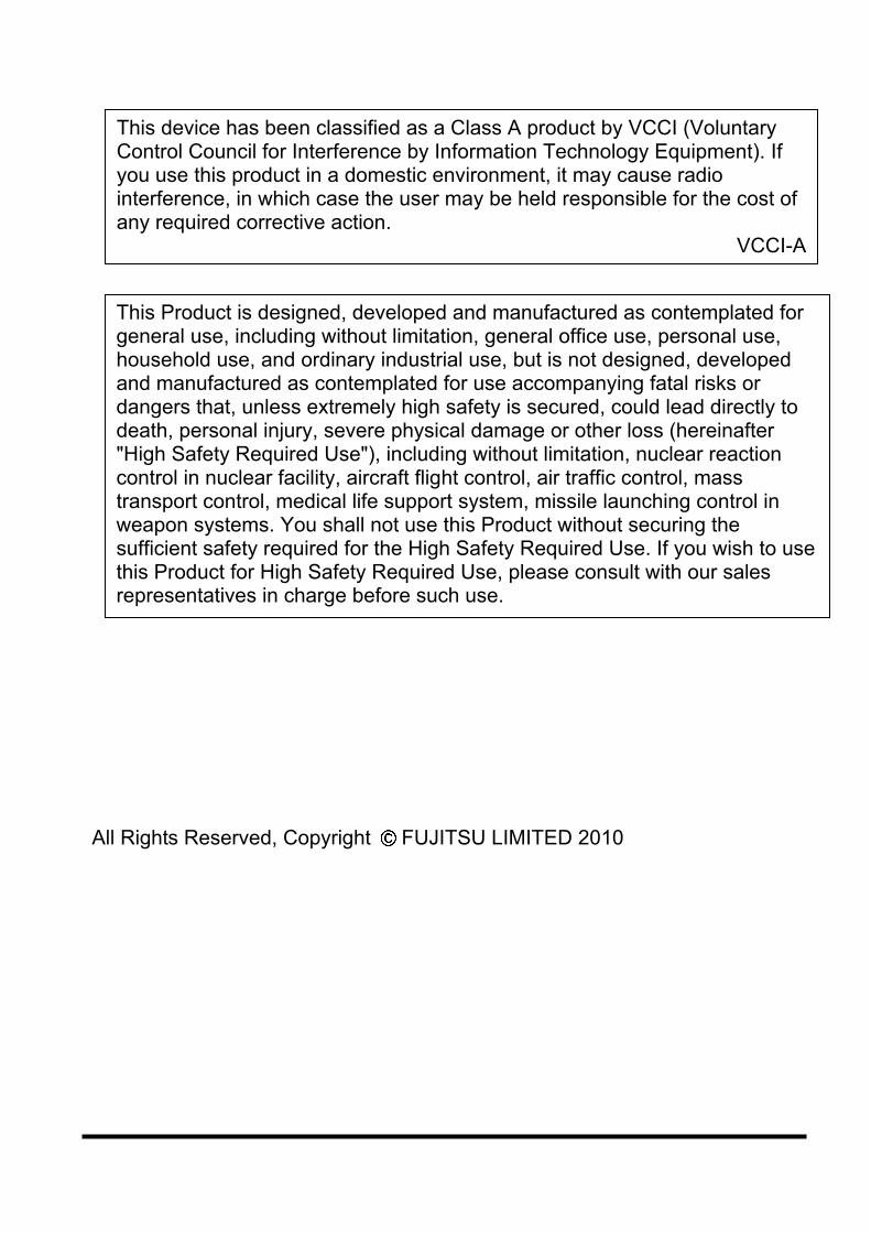
This Product is designed, developed and manufactured as contemplated for general use, including without limitation, general office use, personal use, household use, and ordinary industrial use, but is not designed, developed and manufactured as contemplated for use accompanying fatal risks or dangers that, unless extremely high safety is secured, could lead directly to death, personal injury, severe physical damage or other loss (hereinafter "High Safety Required Use"), including without limitation, nuclear reaction control in nuclear facility, aircraft flight control, air traffic control, mass transport control, medical life support system, missile launching control in weapon systems. You shall not use this Product without securing the sufficient safety required for the High Safety Required Use. If you wish to use this Product for High Safety Required Use, please consult with our sales representatives in charge before such use.
This device has been classified as a Class A product by VCCI (Voluntary Control Council for Interference by Information Technology Equipment). If you use this product in a domestic environment, it may cause radio interference, in which case the user may be held responsible for the cost of any required corrective action.
VCCI-A
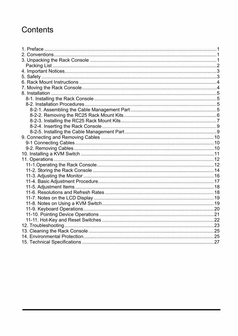
Contents
1. Preface ................................................................................................................................1 2. Conventions.........................................................................................................................1 3. Unpacking the Rack Console ..............................................................................................1
Packing List ..........................................................................................................................2 4. Important Notices.................................................................................................................3 5. Safety ..................................................................................................................................3 6. Rack Mount Instructions ......................................................................................................4 7. Moving the Rack Console....................................................................................................4 8. Installation ...........................................................................................................................5
8-1. Installing the Rack Console ...........................................................................................5 8-2. Installation Procedures..................................................................................................5
8-2-1. Assembling the Cable Management Part ................................................................5 8-2-2. Removing the RC25 Rack Mount Kits.....................................................................6 8-2-3. Installing the RC25 Rack Mount Kits.......................................................................7 8-2-4. Inserting the Rack Console .....................................................................................9 8-2-5. Installing the Cable Management Part ....................................................................9
9. Connecting and Removing Cables ....................................................................................10 9-1 Connecting Cables .......................................................................................................10 9-2. Removing Cables ........................................................................................................10
10. Installing a KVM Switch ...................................................................................................11 11. Operations .......................................................................................................................12
11-1.Operating the Rack Console.......................................................................................12 11-2. Storing the Rack Console ..........................................................................................14 11-3. Adjusting the Monitor .................................................................................................16 11-4. Basic Adjustment Procedure......................................................................................17 11-5. Adjustment Items .......................................................................................................18 11-6. Resolutions and Refresh Rates .................................................................................18 11-7. Notes on the LCD Display .........................................................................................19 11-8. Notes on Using a KVM Switch...................................................................................19 11-9. Keyboard Operations.................................................................................................20 11-10. Pointing Device Operations .....................................................................................21 11-11. Hot-Key and Reset Switches ...................................................................................22
12. Troubleshooting...............................................................................................................23 13. Cleaning the Rack Console .............................................................................................25 14. Environmental Protection.................................................................................................25 15. Technical Specifications ..................................................................................................27
1
1. Preface Thank you for purchasing the Rack Console RC25 (hereinafter called "the Rack Console", "this product", or "this device"). We believe that using this product will greatly improve the efficiency and functionality of your workspace. In addition, our compact slide module design saves space in comparison with previous layouts. The 17-inch TFT monitor can display a resolution of 1280 by 1024 dots with 16,770,000 colours. This product is also equipped with a keyboard and pointing device with two buttons and scrolling function.
2. Conventions Symbols and terminology that are used in this manual are described below.
This symbol indicates the possibility of physical damage (such as damage to this product) or physical injury, which may result through improper operation.
This symbol indicates supplemental information, comments or hints.
Double quotations
Double quotation marks are used to indicate the title of a chapter or document to be referenced, or important terms.
Sequential numbers Sequential numbers preceding text indicate the order of operations described by the text.
3. Unpacking the Rack Console 1. When you unpack the Rack Console, check that it has not been damaged in transit. 2. For detailed instructions of how to unpack the Rack Console, refer to the
"Quick-Start-Guide" provided with this device.
When you remove the product from the package, open the plastic bag that covers the device and directly hold the device to lift it. Otherwise, you may drop the device and it may cause personal injury or damage the device.
CAUTION
CAUTION
2
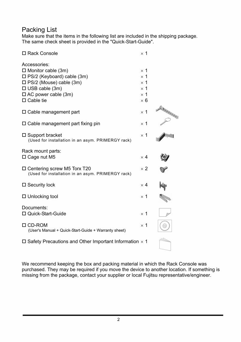
Packing List Make sure that the items in the following list are included in the shipping package. The same check sheet is provided in the "Quick-Start-Guide". Rack Console 1 Accessories: Monitor cable (3m) 1 PS/2 (Keyboard) cable (3m) 1 PS/2 (Mouse) cable (3m) 1 USB cable (3m) 1 AC power cable (3m) 1 Cable tie 6 Cable management part 1 Cable management part fixing pin 1 Support bracket 1
(Used for installation in an asym. PRIMERGY rack) Rack mount parts: Cage nut M5 4 Centering screw M5 Torx T20 2
(Used for installation in an asym. PRIMERGY rack) Security lock 4 Unlocking tool 1 Documents: Quick-Start-Guide 1 CD-ROM 1
(User's Manual + Quick-Start-Guide + Warranty sheet) Safety Precautions and Other Important Information 1 We recommend keeping the box and packing material in which the Rack Console was purchased. They may be required if you move the device to another location. If something is missing from the package, contact your supplier or local Fujitsu representative/engineer.
3
4. Important Notices Chapter 5 and 6 contain cautions that must be taken when you operate the Rack Console, and information related to safety. Carefully read these chapters to use the Rack Console correctly.
5. Safety
Safety Precautions Condensation may occur on this device. Before using the Rack Console, allow it to dry out
completely and to reach the ambient temperature of the installation location. Make sure that the voltage supplied by the outlet to which the device is connected is within
the acceptable range of the device. Also, make sure that the rated voltage meets the specification of the device. (Refer to "15. Technical Specifications" and the model plate on the device.)
The Rack Console's power cable is specially certified. Use it only for the power outlet of the Rack Console. Otherwise, electric shocks or short circuits may occur.
Arrange the immediate area around the Rack Console's power socket and the rack's power outlet so that the plug can be quickly pulled.
Lay all the cables so that they are not damaged. Refer to the relevant sections in "8 Installation" when you connect or remove cables.
Do not connect or remove the data cables during thunderstorms. Be careful not to get any objects, such as necklaces or paperclips caught (or any liquids
spilt) inside the device. In an emergency (e.g., damage to the housing, parts or cables; or if an object or liquid has
fallen into the device), remove all the power cables as soon as possible and contact the store where you purchased the device or a Fujitsu maintenance representative.
Only licensed engineers may repair the device. If any unlicensed user opens the device and makes incorrect repairs, electric shocks or fire may occur.
Note that when the device is open, the corners may cause injury if bumped into. Always be careful when the device is open.
We recommend that you store this device in the rack when it is not in use, or when you operate other devices such as a server or other peripheral equipment.
Using the keyboard when you are in poor health, or using the keyboard for extended periods of time should be avoided.
Always hold the connector portion and do not jerk cables when you remove them. Avoid operating the device with wet hands. Do not insert or remove connectors when your hands are wet. Do not place unnecessary items, such as a cup, on the device. Do not modify or repair the device. Only licensed personnel can dismantle, remove, or replace parts, such as the power
supply unit, which bear a warning mark (such as a lightning bolt mark). You can specify only the resolutions and refresh rates specified in the monitor explanation
in "11-3. Adjusting the Monitor". Contact the store where you purchased the device or a Fujitsu maintenance representative if you have any questions.
The data cables that are used for peripheral equipment must be adequately insulated in order to prevent interference.
To cut the power supplied to this device through the power outlet, unplug the power plug of this device from the power outlet.
CAUTION
4
Follow the instructions in the appropriate section in "13. Cleaning the Rack Console" when you clean this device.
Keep this manual handy for reference with the device at all times. If you give the device to a third party, give the third party this manual as well.
Do not use the device as a stepladder or lean against the device with it drawn out. Doing so may unbalance the rack, causing it to fall over.
Some components of the device (such as LCD, etc.) have a limited service life. In cases of extended continuous use, these components will need early replacement.
The estimated period for reliable use of the device (service life) is 5 years. [Note] This period is estimated under assumption of a usage pattern of 8 hours a day, 200 hours a month, at an ambient temperature of 25°C. This service life (5 years) does not apply for some limited life components.
The socket-outlet shall be installed near the equipment and shall be easily accessible.
6. Rack Mount Instructions Elevated Operating Ambient – If installed in a closed or multi-unit rack assembly, the
operating ambient temperature of the rack environment may be greater than room ambient. Therefore, consideration should be given to installing the equipment in an environment compatible with the maximum ambient temperature (Tma) specified by the manufacturer.
Reduced Air Flow – Installation of the equipment in a rack should be such that the amount of air flow required for safe operation of the equipment is not compromised.
Mechanical Loading – Mounting of the equipment in the rack should be such that a hazardous condition is not achieved due to uneven mechanical loading.
Circuit Overloading – Consideration should be given to the connection of the equipment to the supply circuit and the effect that overloading of the circuits might have on overcurrent protection and supply wiring. Appropriate consideration of equipment nameplate ratings should be used when addressing this concern.
Reliable Earthing – Reliable earthing of rack-mounted equipment should be maintained. Particular attention should be given to supply connections other than direct connections to the branch circuit (e.g. use of power strips).
Slide/rail mounted equipment is not to be used as a shelf or a work space.
7. Moving the Rack Console
When you move the Rack Console to a different location, use the box in which it was purchased, or another box to protect it from damage. Do not unpack the Rack Console before you finish moving the Rack Console.
CAUTION
5
8. Installation
Note the safety information in "Important Notices".
8-1. Installing the Rack Console
Observe the specified environmental conditions when you use the device. (See "15. Technical Specifications" for more information.) Avoid dust, humidity, and extreme temperatures. Installation may require two or more people in some situations. Be careful not to catch your fingers or hands between the guide rails and the device.
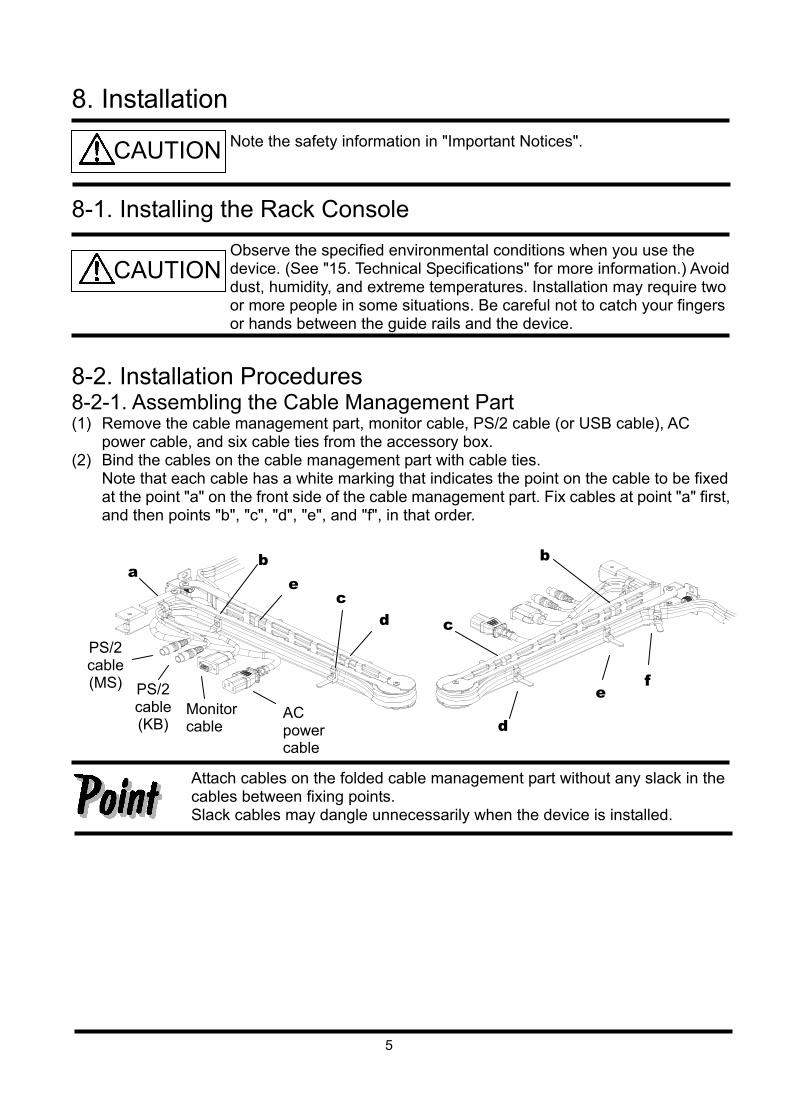
8-2. Installation Procedures 8-2-1. Assembling the Cable Management Part (1) Remove the cable management part, monitor cable, PS/2 cable (or USB cable), AC
power cable, and six cable ties from the accessory box. (2) Bind the cables on the cable management part with cable ties.
Note that each cable has a white marking that indicates the point on the cable to be fixed at the point "a" on the front side of the cable management part. Fix cables at point "a" first, and then points "b", "c", "d", "e", and "f", in that order.
Attach cables on the folded cable management part without any slack in the cables between fixing points. Slack cables may dangle unnecessarily when the device is installed.
CAUTION
CAUTION
d
e f
a b
c
Monitor cable
PS/2 cable (KB)
PS/2 cable (MS)
AC power cable
c d
e
b
6
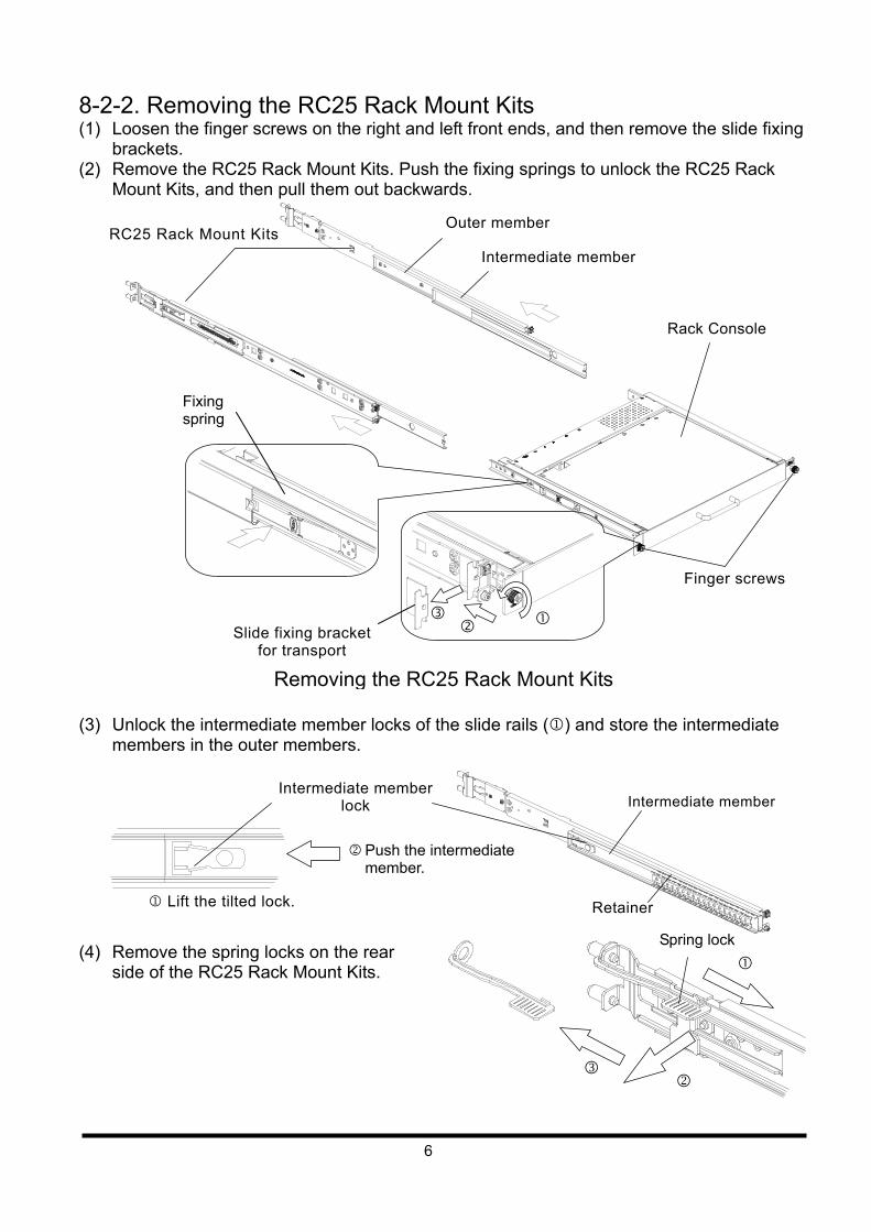
8-2-2. Removing the RC25 Rack Mount Kits (1) Loosen the finger screws on the right and left front ends, and then remove the slide fixing
brackets. (2) Remove the RC25 Rack Mount Kits. Push the fixing springs to unlock the RC25 Rack
Mount Kits, and then pull them out backwards.
(3) Unlock the intermediate member locks of the slide rails () and store the intermediate
members in the outer members.
(4) Remove the spring locks on the rear
side of the RC25 Rack Mount Kits.
Removing the RC25 Rack Mount Kits
Finger screws
Intermediate member
RC25 Rack Mount Kits
Rack Console
Slide fixing bracket for transport
Fixing spring
Spring lock
Retainer
Intermediate member lock
Lift the tilted lock.
Push the intermediate member.
Intermediate member
Outer member
7
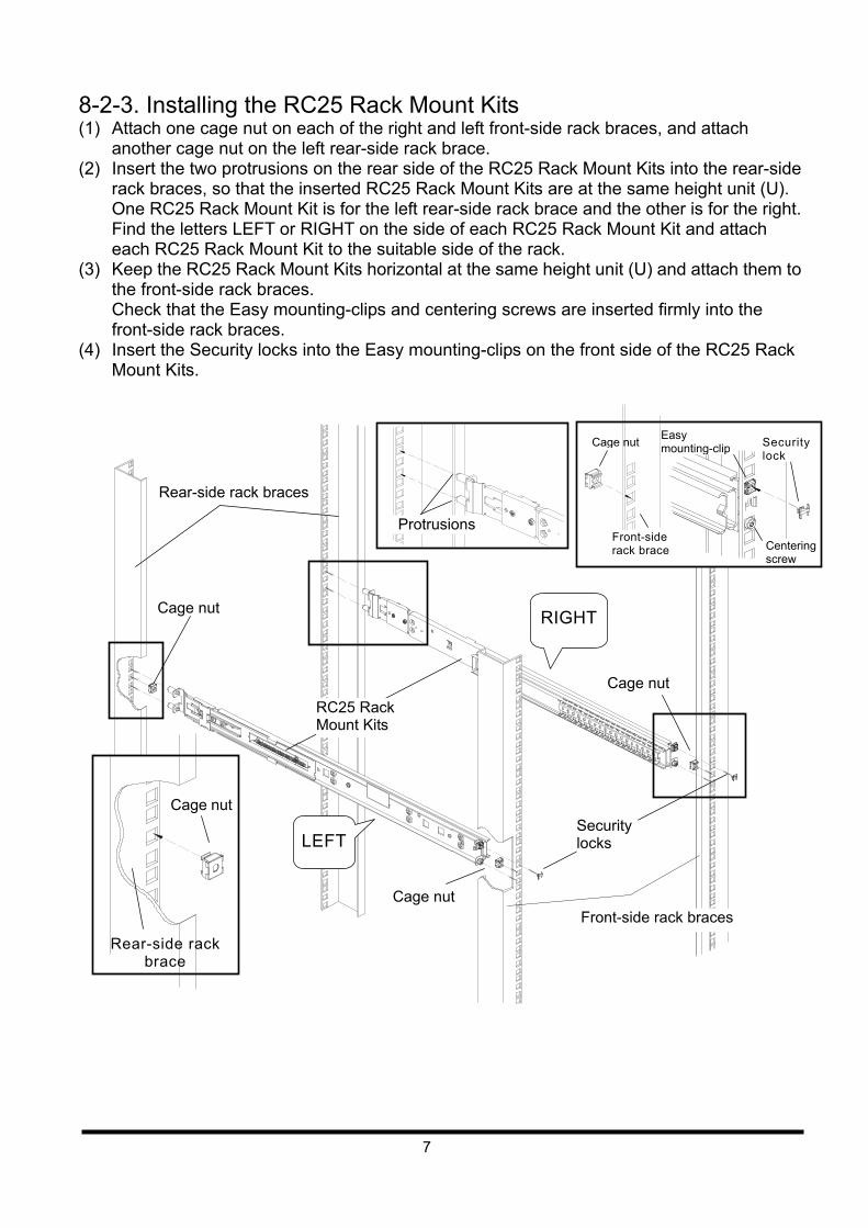
8-2-3. Installing the RC25 Rack Mount Kits (1) Attach one cage nut on each of the right and left front-side rack braces, and attach
another cage nut on the left rear-side rack brace. (2) Insert the two protrusions on the rear side of the RC25 Rack Mount Kits into the rear-side
rack braces, so that the inserted RC25 Rack Mount Kits are at the same height unit (U). One RC25 Rack Mount Kit is for the left rear-side rack brace and the other is for the right. Find the letters LEFT or RIGHT on the side of each RC25 Rack Mount Kit and attach each RC25 Rack Mount Kit to the suitable side of the rack.
(3) Keep the RC25 Rack Mount Kits horizontal at the same height unit (U) and attach them to the front-side rack braces. Check that the Easy mounting-clips and centering screws are inserted firmly into the front-side rack braces.
(4) Insert the Security locks into the Easy mounting-clips on the front side of the RC25 Rack Mount Kits.
Cage nut
Rear-side rack braces
RIGHT
Front-side rack braces
Cage nut
Security locks
Cage nut
Centering screw
Front-side rack brace
Cage nut
Protrusions
Easy mounting-clip Security
lock
RC25 Rack Mount Kits
LEFT
Rear-side rack brace
Cage nut
8
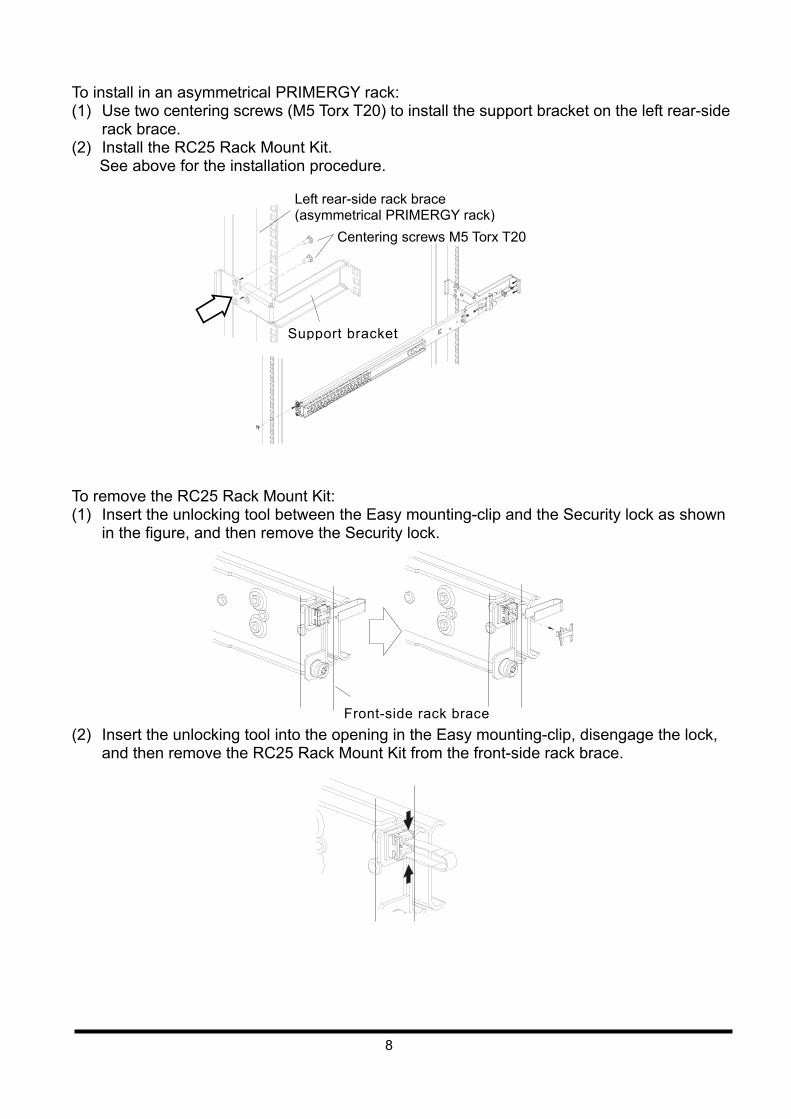
To install in an asymmetrical PRIMERGY rack: (1) Use two centering screws (M5 Torx T20) to install the support bracket on the left rear-side
rack brace. (2) Install the RC25 Rack Mount Kit.
See above for the installation procedure. To remove the RC25 Rack Mount Kit: (1) Insert the unlocking tool between the Easy mounting-clip and the Security lock as shown
in the figure, and then remove the Security lock. (2) Insert the unlocking tool into the opening in the Easy mounting-clip, disengage the lock,
and then remove the RC25 Rack Mount Kit from the front-side rack brace.
Left rear-side rack brace (asymmetrical PRIMERGY rack)
Centering screws M5 Torx T20
Support bracket
Front-side rack brace
9
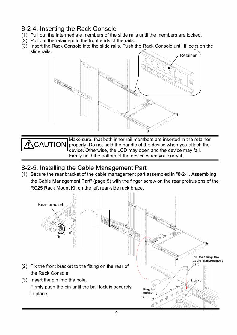
8-2-4. Inserting the Rack Console (1) Pull out the intermediate members of the slide rails until the members are locked. (2) Pull out the retainers to the front ends of the rails. (3) Insert the Rack Console into the slide rails. Push the Rack Console until it locks on the
slide rails.
Make sure, that both inner rail members are inserted in the retainer properly! Do not hold the handle of the device when you attach the device. Otherwise, the LCD may open and the device may fall. Firmly hold the bottom of the device when you carry it.
8-2-5. Installing the Cable Management Part (1) Secure the rear bracket of the cable management part assembled in "8-2-1. Assembling
the Cable Management Part" (page 5) with the finger screw on the rear protrusions of the
RC25 Rack Mount Kit on the left rear-side rack brace.
(2) Fix the front bracket to the fitting on the rear of
the Rack Console.
(3) Insert the pin into the hole.
Firmly push the pin until the ball lock is securely
in place.
Rear bracket
CAUTION
Retainer
Bracket
Pin for fixing the cable management part
Ring for removing the pin
10
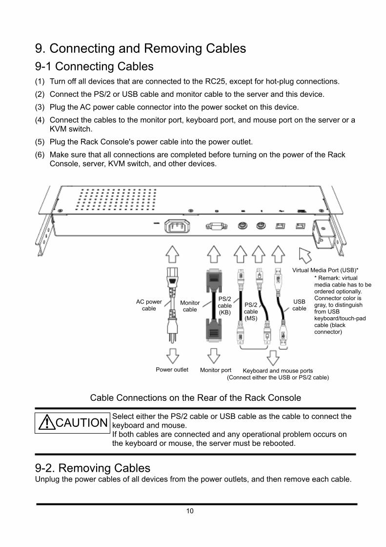
9. Connecting and Removing Cables 9-1 Connecting Cables (1) Turn off all devices that are connected to the RC25, except for hot-plug connections.
(2) Connect the PS/2 or USB cable and monitor cable to the server and this device.
(3) Plug the AC power cable connector into the power socket on this device.
(4) Connect the cables to the monitor port, keyboard port, and mouse port on the server or a KVM switch.
(5) Plug the Rack Console's power cable into the power outlet.
(6) Make sure that all connections are completed before turning on the power of the Rack Console, server, KVM switch, and other devices.
Cable Connections on the Rear of the Rack Console
Select either the PS/2 cable or USB cable as the cable to connect the keyboard and mouse. If both cables are connected and any operational problem occurs on the keyboard or mouse, the server must be rebooted.
9-2. Removing Cables Unplug the power cables of all devices from the power outlets, and then remove each cable.
AC power cable
Monitor cable
USB cable
PS/2 cable (KB)
PS/2 cable (MS)
Keyboard and mouse ports (Connect either the USB or PS/2 cable)
Monitor portPower outlet
CAUTION
Virtual Media Port (USB)** Remark: virtual media cable has to be ordered optionally. Connector color is gray, to distinguish from USB keyboard/touch-pad cable (black connector)
11
10. Installing a KVM Switch To install a KVM switch, follow the instructions in the user's guide of the KVM Integration Kit. For more information on KVM switches that can be installed, contact the store where you purchased the device or a Fujitsu maintenance representative.
When you install a KVM switch, make sure that the power cable of this device is not plugged into a power outlet, to avoid an electric shock or short circuit. This device contains components that generate or accumulate high voltage electricity. Before you install a KVM switch, make sure that the device has been properly discharged. Be careful not to injure yourself with the edges of the metallic parts. Be careful to prevent getting any foreign substances such as metallic pieces, water or other liquids inside the device, to avoid damaging it. Also, do not touch any parts of the device not related to your work.
CAUTION
12
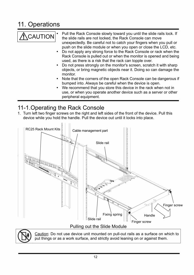
11. Operations
Pull the Rack Console slowly toward you until the slide rails lock. If the slide rails are not locked, the Rack Console can move unexpectedly. Be careful not to catch your fingers when you pull or push on the slide module or when you open or close the LCD, etc.
Do not apply any strong force to the Rack Console or rack when the Rack Console is pulled out or when the monitor is opened and being used, as there is a risk that the rack can topple over.
Do not press strongly on the monitor's screen, scratch it with sharp objects, or bring magnetic objects near it. Doing so can damage the monitor.
Note that the corners of the open Rack Console can be dangerous if bumped into. Always be careful when the device is open.
We recommend that you store this device in the rack when not in use, or when you operate another device such as a server or other peripheral equipment.
11-1.Operating the Rack Console 1. Turn left two finger screws on the right and left sides of the front of the device. Pull this
device while you hold the handle. Pull the device out until it locks into place.
Pulling out the Slide Module
Caution: Do not use device unit mounted on pull-out rails as a surface on which to put things or as a work surface, and strictly avoid leaning on or against them.
Cable management part RC25 Rack Mount Kits
Slide rail Fixing spring
Slide rail
Finger screw
Handle
Finger screw
CAUTION
13
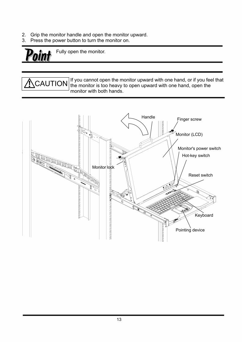
2. Grip the monitor handle and open the monitor upward. 3. Press the power button to turn the monitor on. Fully open the monitor.
If you cannot open the monitor upward with one hand, or if you feel that the monitor is too heavy to open upward with one hand, open the monitor with both hands.
Monitor (LCD)
Handle
Monitor's power switch
Hot-key switch
Reset switch
Finger screw
Monitor lock
Pointing device
Keyboard
CAUTION
14
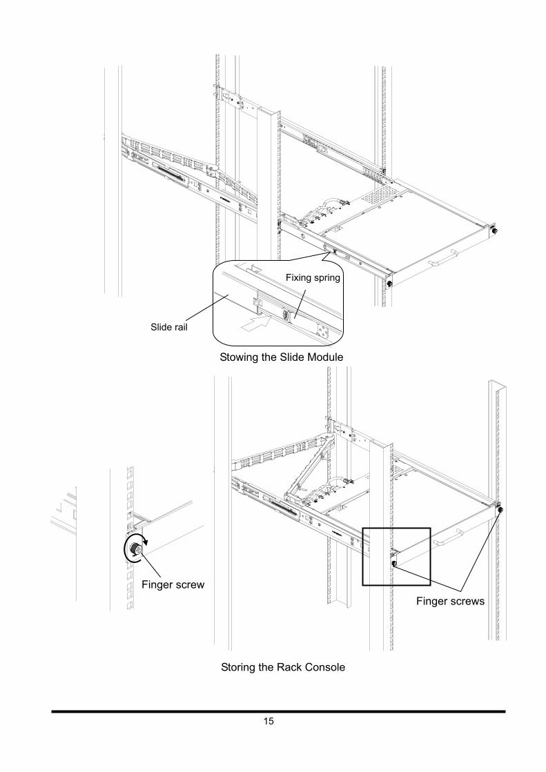
11-2. Storing the Rack Console The device can be stored in the rack when the monitor and keyboard are not used.
Slowly slide the Rack Console in and out of the rack.
1. Press the monitor power button to turn off the monitor. 2. Make sure that nothing is connected to the USB port on the front side of the device, and
then hold the handle and slowly close the LCD monitor. Make sure that the LCD monitor is locked.
3. Push the fixing springs on the right and left sides of the slide rail, and slide the device back into the rack.
4. Tighten the finger screws on the right and left front ends of the device.
Be careful not to pinch your hands or fingers in the slide rails or Rack Console itself when you stow the Rack Console.
To save electricity and extend the life of the monitor, when the monitor is not in use, turn off the power of the monitor or store the Rack Console in the rack. Storing this device in the rack automatically turns off the power of the monitor.
CAUTION
15
Finger screws
Slide rail
Fixing spring
Stowing the Slide Module
Storing the Rack Console
Finger screw
16
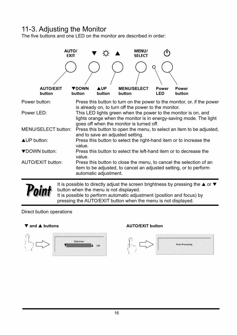
11-3. Adjusting the Monitor The five buttons and one LED on the monitor are described in order:
Power button: Press this button to turn on the power to the monitor, or, if the power
is already on, to turn off the power to the monitor. Power LED: This LED lights green when the power to the monitor is on, and
lights orange when the monitor is in energy-saving mode. The light goes off when the monitor is turned off.
MENU/SELECT button: Press this button to open the menu, to select an item to be adjusted, and to save an adjusted setting.
UP button: Press this button to select the right-hand item or to increase the value.
DOWN button: Press this button to select the left-hand item or to decrease the value.
AUTO/EXIT button: Press this button to close the menu, to cancel the selection of an item to be adjusted, to cancel an adjusted setting, or to perform automatic adjustment.
It is possible to directly adjust the screen brightness by pressing the or button when the menu is not displayed. It is possible to perform automatic adjustment (position and focus) by pressing the AUTO/EXIT button when the menu is not displayed.
Direct button operations
AUTO/EXIT button
DOWN button
UP button
MENU/SELECT button
Power LED
Power button
and buttons AUTO/EXIT button
17
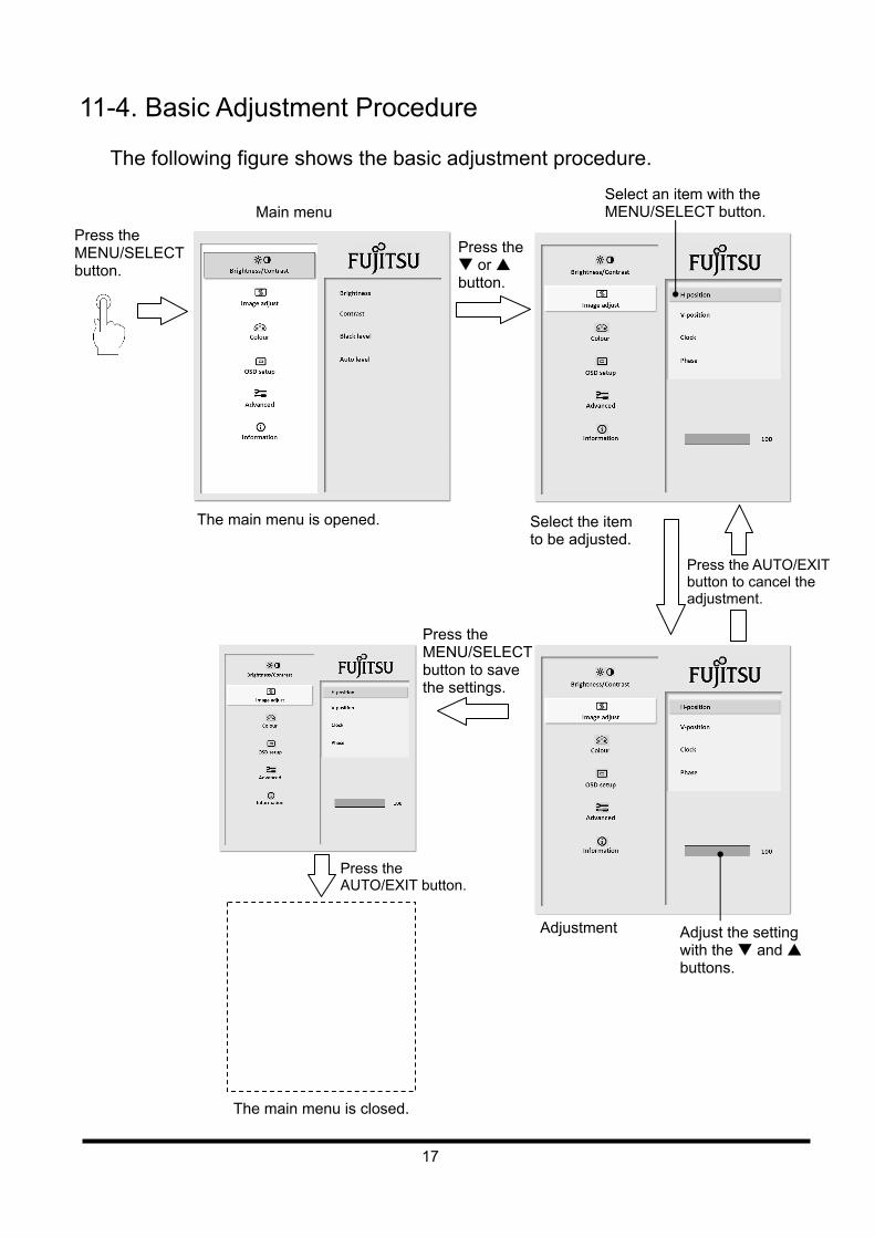
11-4. Basic Adjustment Procedure The following figure shows the basic adjustment procedure.
Press the MENU/SELECT button.
Main menu
Press the or button.
The main menu is opened. Select the item to be adjusted.
Adjust the setting with the and buttons.
Press the MENU/SELECT button to save the settings.
Press the AUTO/EXIT button to cancel the adjustment.
Adjustment
Press the AUTO/EXIT button.
The main menu is closed.
Select an item with the MENU/SELECT button.
18
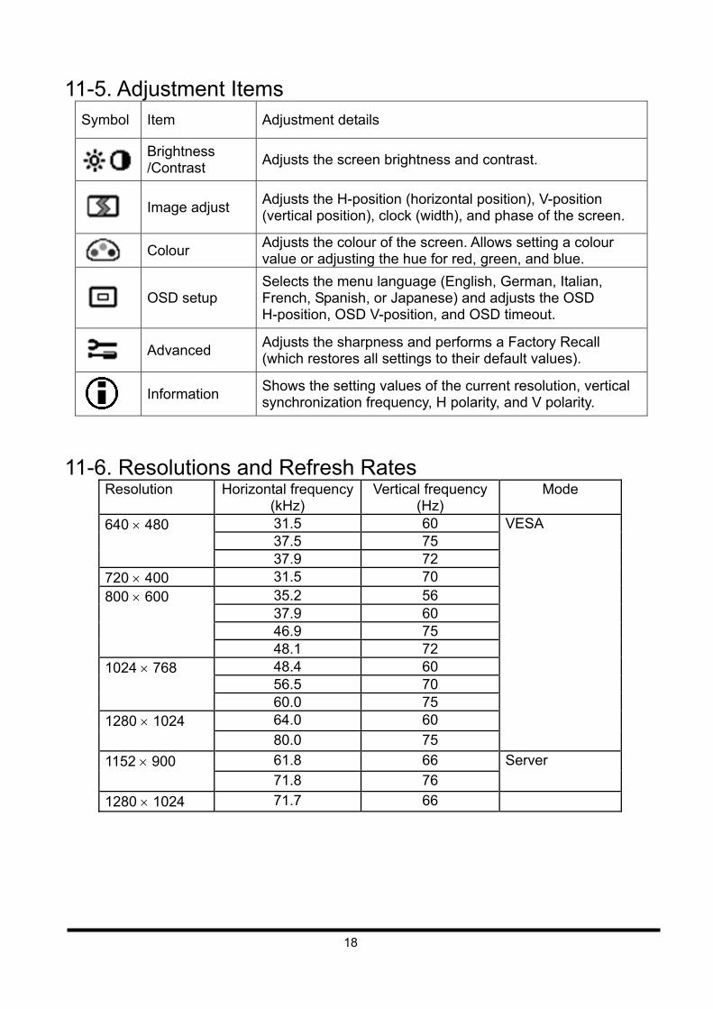
11-5. Adjustment Items Symbol Item Adjustment details
Brightness /Contrast
Adjusts the screen brightness and contrast.
Image adjust
Adjusts the H-position (horizontal position), V-position (vertical position), clock (width), and phase of the screen.
Colour
Adjusts the colour of the screen. Allows setting a colour value or adjusting the hue for red, green, and blue.
OSD setup
Selects the menu language (English, German, Italian, French, Spanish, or Japanese) and adjusts the OSD H-position, OSD V-position, and OSD timeout.
Advanced
Adjusts the sharpness and performs a Factory Recall (which restores all settings to their default values).
Information
Shows the setting values of the current resolution, vertical synchronization frequency, H polarity, and V polarity.
11-6. Resolutions and Refresh Rates Resolution Horizontal frequency
(kHz) Vertical frequency
(Hz) Mode
31.5 60 37.5 75
640 480
37.9 72 720 400 31.5 70
35.2 56 37.9 60 46.9 75
800 600
48.1 72 48.4 60 56.5 70
1024 768
60.0 75 64.0 60 1280 1024
80.0 75
VESA
61.8 66 1152 900
71.8 76
Server
1280 1024 71.7 66
19
11-7. Notes on the LCD Display While the on-screen display may shift, blink, or otherwise be disturbed just after the power is turned on or the OS starts up/shuts down, this does not indicate a machine failure, and the device may be used normally. While 1280 1024 is the native full-screen resolution, the LCD display is full screen for all resolutions. For resolutions other than 1280 1024, characters may be blurred and the thickness of thin lines can be uneven. This is because the full-screen display is made by digital interpolation of the low-res output, not by physical magnification. This is not a machine failure, and the device may be used normally. Although there might be some always-off dots or some always-on dots, this is accepted as it is a natural characteristic of LCDs, not as a fatal imperfection. So use this device normally.
11-8. Notes on Using a KVM Switch When a KVM switch is used for multiple servers equipped with various types of CRT controllers, the image display position on the screen may be different between servers even though the screen setting is the same for all servers. In general, the resolution and refresh rate (vertical frequency) settings are the same for all servers, and only one set of parameters for these settings are stored for the screen. Adjusting a shifted screen image for a server may affect the display positions for the other servers. To correct a shifted image without affecting the display positions for other servers, change the settings as follows: 1. Change the refresh rate for the server whose display setting must be adjusted. 2. Adjust the display setting properly and save it. In general, you can set multiple refresh rates for one resolution. By using this function, you can set and use multiple setting options for the screen.
20
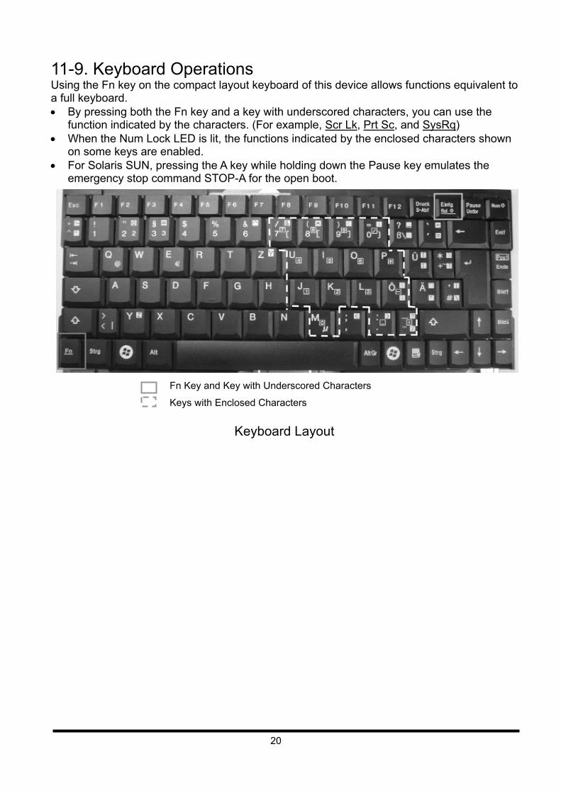
11-9. Keyboard Operations Using the Fn key on the compact layout keyboard of this device allows functions equivalent to a full keyboard. By pressing both the Fn key and a key with underscored characters, you can use the
function indicated by the characters. (For example, Scr Lk, Prt Sc, and SysRq) When the Num Lock LED is lit, the functions indicated by the enclosed characters shown
on some keys are enabled. For Solaris SUN, pressing the A key while holding down the Pause key emulates the
emergency stop command STOP-A for the open boot. Fn Key and Key with Underscored Characters
Keys with Enclosed Characters
Keyboard Layout
21
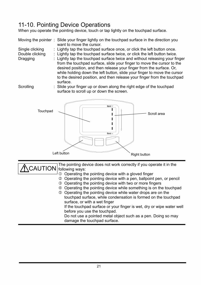
11-10. Pointing Device Operations When you operate the pointing device, touch or tap lightly on the touchpad surface. Moving the pointer : Slide your finger lightly on the touchpad surface in the direction you
want to move the cursor. Single clicking : Lightly tap the touchpad surface once, or click the left button once. Double clicking : Lightly tap the touchpad surface twice, or click the left button twice. Dragging : Lightly tap the touchpad surface twice and without releasing your finger
from the touchpad surface, slide your finger to move the cursor to the desired position, and then release your finger from the surface. Or, while holding down the left button, slide your finger to move the cursor to the desired position, and then release your finger from the touchpad surface.
Scrolling : Slide your finger up or down along the right edge of the touchpad surface to scroll up or down the screen.
The pointing device does not work correctly if you operate it in the following ways: Operating the pointing device with a gloved finger Operating the pointing device with a pen, ballpoint pen, or pencil Operating the pointing device with two or more fingers Operating the pointing device while something is on the touchpad Operating the pointing device while water drops are on the
touchpad surface, while condensation is formed on the touchpad surface, or with a wet finger If the touchpad surface or your finger is wet, dry or wipe water well before you use the touchpad. Do not use a pointed metal object such as a pen. Doing so may damage the touchpad surface.
Touchpad
Left button Right button
Scroll area
CAUTION
22
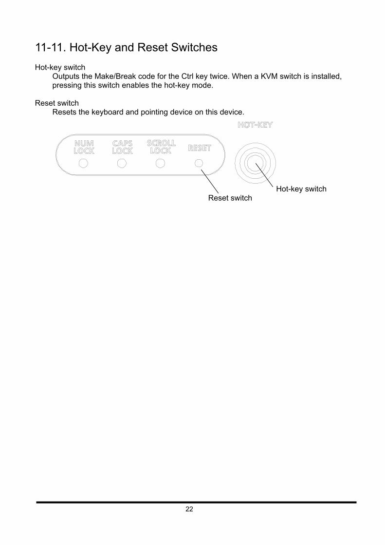
11-11. Hot-Key and Reset Switches Hot-key switch
Outputs the Make/Break code for the Ctrl key twice. When a KVM switch is installed, pressing this switch enables the hot-key mode.
Reset switch
Resets the keyboard and pointing device on this device.
Reset switch Hot-key switch
23
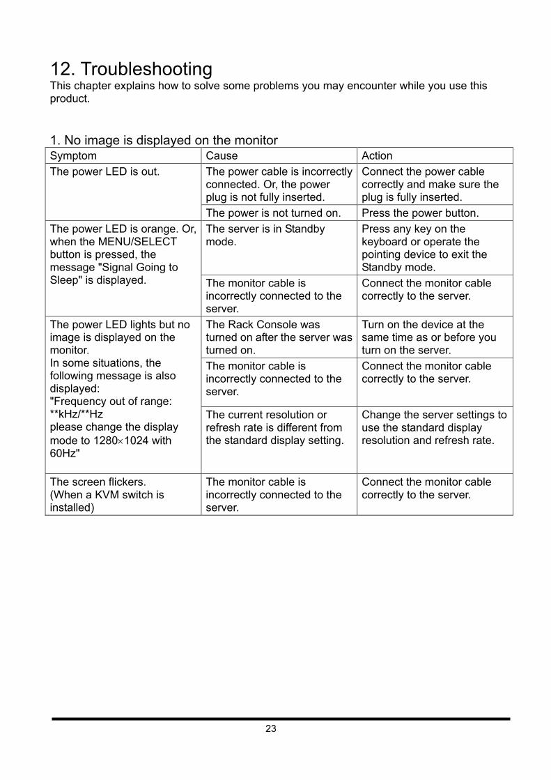
12. Troubleshooting This chapter explains how to solve some problems you may encounter while you use this product. 1. No image is displayed on the monitor Symptom Cause Action
The power cable is incorrectly connected. Or, the power plug is not fully inserted.
Connect the power cable correctly and make sure the plug is fully inserted.
The power LED is out.
The power is not turned on. Press the power button.
The server is in Standby mode.
Press any key on the keyboard or operate the pointing device to exit the Standby mode.
The power LED is orange. Or, when the MENU/SELECT button is pressed, the message "Signal Going to Sleep" is displayed. The monitor cable is
incorrectly connected to the server.
Connect the monitor cable correctly to the server.
The Rack Console was turned on after the server was turned on.
Turn on the device at the same time as or before you turn on the server.
The monitor cable is incorrectly connected to the server.
Connect the monitor cable correctly to the server.
The power LED lights but no image is displayed on the monitor. In some situations, the following message is also displayed: "Frequency out of range: **kHz/**Hz please change the display mode to 12801024 with 60Hz"
The current resolution or refresh rate is different from the standard display setting.
Change the server settings to use the standard display resolution and refresh rate.
The screen flickers. (When a KVM switch is installed)
The monitor cable is incorrectly connected to the server.
Connect the monitor cable correctly to the server.
24
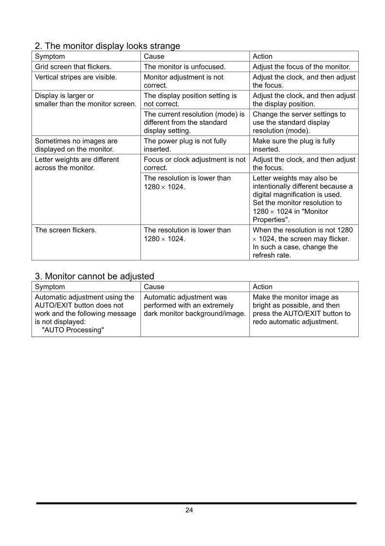
2. The monitor display looks strange Symptom Cause Action
Grid screen that flickers. The monitor is unfocused. Adjust the focus of the monitor.
Vertical stripes are visible. Monitor adjustment is not correct.
Adjust the clock, and then adjust the focus.
The display position setting is not correct.
Adjust the clock, and then adjust the display position.
Display is larger or smaller than the monitor screen.
The current resolution (mode) is different from the standard display setting.
Change the server settings to use the standard display resolution (mode).
Sometimes no images are displayed on the monitor.
The power plug is not fully inserted.
Make sure the plug is fully inserted.
Focus or clock adjustment is not correct.
Adjust the clock, and then adjust the focus.
Letter weights are different across the monitor.
The resolution is lower than 1280 1024.
Letter weights may also be intentionally different because a digital magnification is used. Set the monitor resolution to 1280 1024 in "Monitor Properties".
The screen flickers. The resolution is lower than 1280 1024.
When the resolution is not 1280 1024, the screen may flicker. In such a case, change the refresh rate.
3. Monitor cannot be adjusted Symptom Cause Action
Automatic adjustment using the AUTO/EXIT button does not work and the following message is not displayed:
"AUTO Processing"
Automatic adjustment was performed with an extremely dark monitor background/image.
Make the monitor image as bright as possible, and then press the AUTO/EXIT button to redo automatic adjustment.

25
13. Cleaning the Rack Console
Turn off the power and unplug the power cable from the power socket. Do not use cleansers that contain abrasives, or organic solvents such as benzene, thinner, or alcohol. Do not apply water, soap, or spray-type cleaners directly onto the Rack Console. If liquids enter the interior of the Rack Console, it can cause malfunctions or damage.
Wipe the device and monitor cabinet with a clean dry cloth. If there is excessive dirt, wipe it
off with a soft, damp cloth that has been thoroughly wrung out. Remove dust with a soft brush.
Clean the keyboard and pointing device with a soft, dry cloth such as gauze. If there is
excessive dirt, wipe it off with a cloth that has been damped with water or neutral detergent diluted with water and has been thoroughly wrung out. After you use a neutral detergent, wipe off the detergent on the device with a damp cloth that has been thoroughly wrung out. Remove dust with a soft brush.
Clean the monitor screen with a soft dry cloth such as gauze.
Remove dust with a soft brush.
14. Environmental Protection Environmentally-friendly product design and development
This product has been designed in accordance with the Fujitsu standard for "environmentally friendly product design and development". This means that key factors such as durability, selection and labeling of materials, emissions, packaging, ease of dismantling and recycling have been taken into account. This saves resources and thus reduces the harm done to the environment. Further information can be found at: http://ts.fujitsu.com/products/standard_servers/index.html (for the EMEA market) http://primeserver.fujitsu.com/primergy/concept/ (for the Japanese market)
Energy-saving information
Devices that do not need to be constantly switched on should be switched off until they are needed as well as during long breaks and after completion of work.
Packaging information
This packaging information doesn’t apply to the Japanese market. Do not throw away the packaging. You may need it later for transporting the system. If possible, the equipment should only be transported in its original packaging.
CAUTION

26
Information on handling consumables
Please dispose of printer consumables and batteries in accordance with the applicable national regulations. In accordance with EU directives, batteries must not be disposed of with unsorted domestic waste. They can be returned free of charge to the manufacturer, dealer or an authorized agent for recycling or disposal. All batteries containing pollutants are marked with a symbol (a crossed-out garbage can). They are also marked with the chemical symbol for the heavy metal that causes them to be categorized as containing pollutants: Cd Cadmium Hg Mercury Pb Lead
Labels on plastic casing parts
Please avoid sticking your own labels on plastic parts wherever possible, since this makes it difficult to recycle them.
Returns, recycling and disposal
Please handle returns, recycling and disposal in accordance with local regulations.
The device must not be disposed of with domestic waste. This device is labeled in compliance with European directive 2002/96/EC on waste electrical and electronic equipment (WEEE). This directive sets the framework for returning and recycling used equipment and is valid across the EU. When returning your used device, please use the return and collection systems available to you. Further information can be found at http://ts.fujitsu.com/recycling.
Details regarding the return and recycling of devices and consumables within Europe can also be found in the "Returning used devices" manual, via your local Fujitsu branch or from our recycling center in Paderborn: Fujitsu Technology Solutions Recycling Center D-33106 Paderborn Tel. +49 5251 8 18010 Fax +49 5251 8 333 18010
27
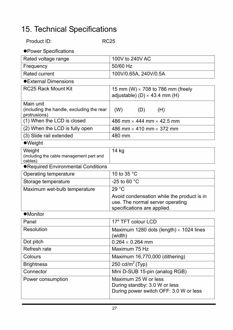
15. Technical Specifications
Product ID: RC25
Power Specifications
Rated voltage range 100V to 240V AC
Frequency 50/60 Hz
Rated current 100V/0.65A, 240V/0.5A
External Dimensions
RC25 Rack Mount Kit 15 mm (W) 708 to 786 mm (freely adjustable) (D) 43.4 mm (H)
Main unit (including the handle, excluding the rear protrusions)
(W) (D) (H)
(1) When the LCD is closed 486 mm 444 mm 42.5 mm
(2) When the LCD is fully open 486 mm 410 mm 372 mm
(3) Slide rail extended 480 mm
Weight
Weight (including the cable management part and cables)
14 kg
Required Environmental Conditions
Operating temperature 10 to 35 °C
Storage temperature -25 to 60 °C
Maximum wet-bulb temperature 29 °C
Avoid condensation while the product is in use. The normal server operating specifications are applied.
Monitor
Panel 17" TFT colour LCD
Resolution Maximum 1280 dots (length) 1024 lines (width)
Dot pitch 0.264 0.264 mm
Refresh rate Maximum 75 Hz
Colours Maximum 16,770,000 (dithering)
Brightness 250 cd/m2 (Typ)
Connector Mini D-SUB 15-pin (analog RGB)
Power consumption Maximum 25 W or less During standby: 3.0 W or less During power switch OFF: 3.0 W or less
28
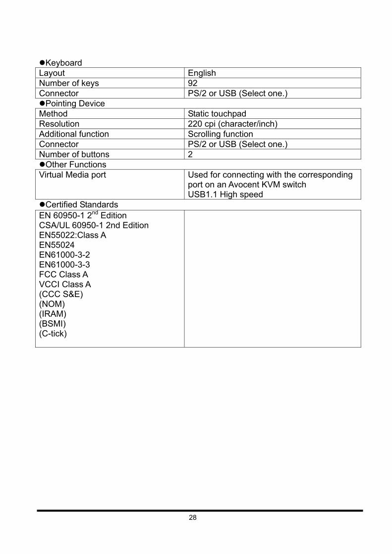
Keyboard Layout English
Number of keys 92
Connector PS/2 or USB (Select one.) Pointing Device Method Static touchpad
Resolution 220 cpi (character/inch) Additional function Scrolling function
Connector PS/2 or USB (Select one.) Number of buttons 2
Other Functions Virtual Media port Used for connecting with the corresponding
port on an Avocent KVM switch USB1.1 High speed
Certified Standards EN 60950-1 2nd Edition CSA/UL 60950-1 2nd Edition EN55022:Class A EN55024 EN61000-3-2
EN61000-3-3 FCC Class A VCCI Class A (CCC S&E) (NOM) (IRAM) (BSMI) (C-tick)
43cm/17" TFT Rack Console (RC25)
User's Manual
Published September 2010 First Edition
Published by FUJITSU LIMITED
The content of this manual may be modified without prior notice. Fujitsu bears no responsibility for infringement of patent or other rights of third
parties ascribable to the use of data in this manual. Reprinting of this manual without permission is prohibited.
NC14010-L591 02 101122