Embed Size (px)
Citation preview
omega.com e-mail: [email protected]
For latest product manuals:omegamanual.info
User’s Guide
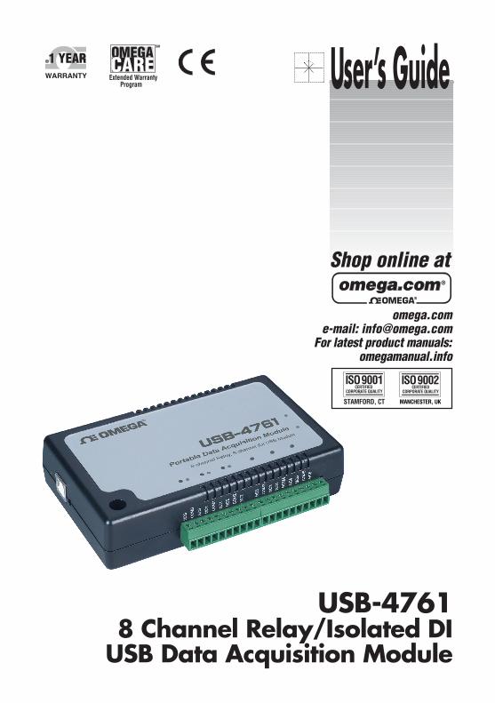
USB-47618 Channel Relay/Isolated DI
USB Data Acquisition Module
Shop online at
Servicing North America:U.S.A.: One Omega Drive, Box 4047ISO 9001 Certified Stamford, CT 06907-0047
Tel: (203) 359-1660FAX: (203) 359-7700e-mail: [email protected]
Canada: 976 BergarLaval (Quebec) H7L 5A1, CanadaTel: (514) 856-6928FAX: (514) 856-6886e-mail: [email protected]
For immediate technical or application assistance:U.S.A. and Canada: Sales Service: 1-800-826-6342/1-800-TC-OMEGA®
Customer Service: 1-800-622-2378/1-800-622-BEST®
Engineering Service: 1-800-872-9436/1-800-USA-WHEN®
Mexico: En Espanol: (001) 203-359-7803FAX: ( 001) 203-359-7807e-mail: [email protected]@omega.com.mx
Servicing Europe:Czech Republic: Frystatska 184, 733 01 Karviná, Czech Republic
Tel: +420 (0)59 6311899FAX: +420 (0)59 6311114Toll Free: 0800-1-66342e-mail: [email protected]
Germany/Austria: Daimlerstrasse 26, D-75392 Deckenpfronn, GermanyTel: +49 (0)7056 9398-0FAX: +49 (0)7056 9398-29Toll Free in Germany: 0800 639 7678e-mail: [email protected]
United Kingdom: One Omega Drive, River Bend Technology CentreISO 9002 Certified Northbank, Irlam, Manchester
M44 5BD United KingdomTel: +44 (0)161 777 6611FAX: +44 (0)161 777 6622Toll Free in United Kingdom: 0800-488-488e-mail: [email protected]
OMEGAnet® Online Service Internet e-mailomega.com [email protected]
It is the policy of OMEGA Engineering, Inc. to comply with all worldwide safety and EMC/EMIregulations that apply. OMEGA is constantly pursuing certification of its products to the European NewApproach Directives. OMEGA will add the CE mark to every appropriate device upon certification.The information contained in this document is believed to be correct, but OMEGA accepts no liability for anyerrors it contains, and reserves the right to alter specifications without notice.WARNING: These products are not designed for use in, and should not be used for, human applications.
USB-4761
8-channel Relay / Isolated DI USB Data Acquisition Module
User Manual
Contents
Chapter 1 Introduction ..................................................... 2
1.1 Features ............................................................................. 2 1.1.1 Robust Protection ........................................................... 3 1.1.2 Wide Input Range .......................................................... 3 1.1.3 Reset Protection for Industrial Applications .................. 3 1.1.4 Plug & Play Function ..................................................... 3
1.2 Applications ...................................................................... 4 1.3 Installation Guide .............................................................. 4
Figure 1.1:Installation Flow Chart ................................. 5 1.4 Software Overview............................................................ 6
1.4.1 Programming Choices for DA&C Module: ................... 6 1.4.2 Device Drivers ............................................................... 6
1.5 Device Driver Programming ............................................. 7 1.5.1 Programming Tools ....................................................... 7 1.5.2 Programming with Device Drivers Function Library .... 8 1.5.3 Troubleshooting Device Drivers Error .......................... 8
Chapter 2 Installation ..................................................... 10 2.1 Unpacking ....................................................................... 10 2.2 Driver Installation ........................................................... 11
Figure 2.1: Software Setup .......................................... 11 2.3 Hardware Installation ...................................................... 12
Figure 2.2:Device Name on the Device Manager ........ 13 Figure 2.3:The (!) Indicates Improper Installation ...... 14
2.4 Device Setup & Configuration ........................................ 14 2.4.1 Setting Up the Device .................................................. 14
Figure 2.4:Device Manager Dialog Box ...................... 15 2.4.2 Configuring the Device ................................................ 15
Figure 2.5:The Device Setting Dialog Box ................. 16 2.5 Device Testing................................................................. 16
2.5.1 Testing Digital Input Function ..................................... 17 Figure 2.6:Digital Input Tab in Device Test Dialog .... 17
2.5.2 Testing Digital Output Function .................................. 17 Figure 2.7:Digital Output Tab in Device Test Dialog . 18
2.6 Hardware Uninstallation ................................................. 18 Figure 2.8:Unplug or Eject Hardware Dialog .............. 19 Figure 2.9:Stop a Hardware device dialog box ............ 19
Chapter 3 Signal Connections ........................................ 22 3.1 Overview ......................................................................... 22 3.2 I/O Connectors ................................................................ 22
3.2.1 Pin Assignment ............................................................ 22 Figure 3.1:I/O Connector Pin Assignment .................. 23
3.2.2 I/O Connector Signal Description ................................ 24
v Table of Contents
Table 3.1:I/O Connector Signal Description ............... 24 3.2.3 LED Indicator Status Description ................................ 24
Table 3.2:LED Indicator Status Description ................ 24 3.3 Isolated Digital Input Connections.................................. 25
3.3.1 Single-ended Channel Connections ............................. 25 Figure 3.2:Isolated Digital Input Connections ............. 25
3.4 Relay Connections........................................................... 25 Figure 3.3:Relay Output Channel Connections ........... 25
3.5 Field Wiring Considerations ........................................... 26 Appendix A Specifications ................................................. 28
A.1 Isolated Digital Input....................................................... 28 A.2 Relay Output ................................................................... 28 A.3 General ............................................................................ 29
Appendix B Function Block............................................... 32
USB-4761 User Manual vi
1 2
Introduction
This chapter will provide information on the features of the DAS module, a quick start guide for installation, and some brief information on software and accessories for the USB-4761 Module. Sections include:
• Features
• Applications
• Installation Guide
• Software Overview
• Device Driver Programming
Chapter 1 Introduction
Thank you for buying the USB-4761 data acquisition module. The USB-4761 is a powerful data acquisition (DAS) module for the USB port. It features a unique circuit design and complete functions for data acquisition and control.
1.1 Features
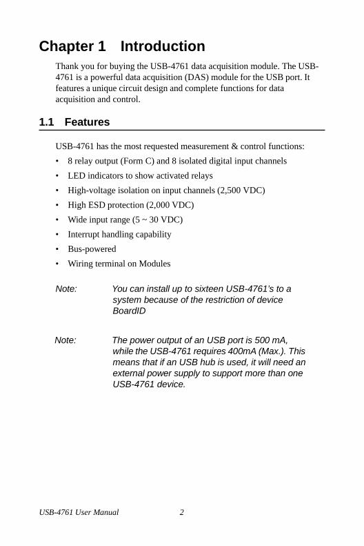
USB-4761 has the most requested measurement & control functions:
• 8 relay output (Form C) and 8 isolated digital input channels
• LED indicators to show activated relays
• High-voltage isolation on input channels (2,500 VDC)
• High ESD protection (2,000 VDC)
• Wide input range (5 ~ 30 VDC)
• Interrupt handling capability
• Bus-powered
• Wiring terminal on Modules
Note: You can install up to sixteen USB-4761’s to a
system because of the restriction of device BoardID
Note: The power output of an USB port is 500 mA, while the USB-4761 requires 400mA (Max.). This means that if an USB hub is used, it will need an external power supply to support more than one USB-4761 device.
USB-4761 User Manual 2
1.1.1 Robust Protection The USB-4761 digital input channels feature a robust isolation protection for industrial, lab and machinery automation applications. It durably withstands voltage up to 2,500 VDC, preventing your host system from any incidental harms. If connected to an external input source with surge protection, the USB-4761 can offer up to a maximum of 2,000 VDC ESD (Electrostatic Discharge) protection.
1.1.2 Wide Input Range The USB-4761 has a wide range of input voltage from 5 to 30 VDC, and it is suitable for most industrial applications with 12 and 24 VDC input volt- age.
1.1.3 Reset Protection for Industrial Applications When the system has undergone a hot reset (i.e. without turning off the system power), USB-4761 can either retain outputs values of each chan- nel, or return to its default configuration as open status, depending on its onboard jumper setting. This function protects the system from wrong operations during unexpected system resets.
1.1.4 Plug & Play Function USB-4761 is a portable Plug-&-Play device that fully complies with the USB 1.1/2.0 specification. During module installation, all bus-related configurations such as base I/O address and interrupts are conveniently taken care of by the Plug-&-Play function. You have virtually no need to set any jumpers or DIP switches.
Note: For detailed specifications of USB-4761, please
refer to Appendix A, Specifications.
3 Chapter 1
1.2 Applications
• Industrial On/Off control
• Switch status sensing
• Digital I/O control
• Industrial and lab automation
• SMT/PCB machinery
• Semi-conductor machinery
• PC-based Industrial Machinery
• Testing & Measurement
• Laboratory & Education
• External relay driving 1.3 Installation Guide
Before you install your USB-4761 module, please make sure you have the following necessary components:
• USB-4761 DAS Module
• Shielded USB 2.0 cable (1.8 m)
• Driver software DLL drivers (included in the companion CD-ROM)
• Personal computer or workstation with a USB port (running Windows
2000, or XP)
After you have the necessary components and maybe some accessories for enhanced operation of your USB DAS module, you can then begin the installation procedure. Figure 1.1 on the next page provides a concise flow chart to give a broad picture of the software and hardware installa- tion procedures.
USB-4761 User Manual 4
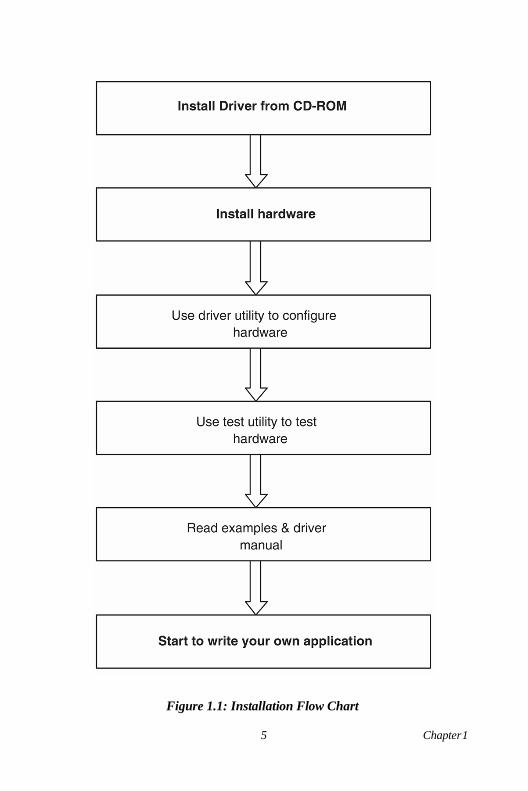
Figure 1.1: Installation Flow Chart
5 Chapter 1
1.4 Software Overview
OMEGA offers a rich set of DLL drivers, third-party driver support and application software to help fully exploit the functions of your USB-4761 module:
• Device Drivers (on the companion CD-ROM)
1.4.1 Programming Choices for DA&C Module: You may use the application software like the Device Drivers. On the other hand, advanced users are allowed to use register- level programming as another option, although this is not recommended due to its laborious and time-consuming nature.
1.4.2 Device Drivers The Device Drivers software is included on the companion CD-ROM. The Device Drivers features a complete I/O function library to help boost your application performance. The Device Drivers for Windows 2000/XP works seamlessly with development tools such as Visual C++, Visual Basic.
USB-4761 User Manual 6
1.5 Device Driver Programming
This section will provide a roadmap to demonstrate how to build an appli- cation from scratch using the Device Drivers with your favorite development tools such as Visual C++, Visual Basic. The step-by-step instructions on how to build your own applications using each development tool will be given in the Device Drivers Manual. Moreover, a rich set of example source code is also given for your reference.
1.5.1 Programming Tools Programmers can develop application programs with the following devel- opment tools:
• Visual C++
• Visual Basic
For instructions on how to begin programming in each development tool, a Tutorial Chapter in the Device Drivers Manual is included for your reference. Please refer to the corresponding sections in this chapter on the Device Drivers Manual to begin your programming efforts. You can also look at the example source code provided for each programming tool, since they can get you very well oriented. The Device Drivers Manual can be found on the companion CD-ROM. Alternatively, if you have already installed the Device Drivers on your system, The Device Drivers Manual can be readily accessed through the Start button:
Start/Programs/Omega USB-4700 Series/Device Driver’s Manual The example source code can be found under the corresponding installa- tion folder such as the default installation path:
C:/Program Files/Omega/USB-4700/Examples For information about using other function groups or other development tools, please refer to Creating Windows 2000/XP Applications with Device Drivers chapter and the Function Overview chapter in the Device Drivers Manual.
7 Chapter 1
1.5.2 Programming with Device Drivers Function Library The Device Drivers offer a rich function library that can be utilized in various application programs. This function library consists of numerous APIs that support many development tools, such as Visual C++, Visual Basic.
1.5.3 Troubleshooting Device Drivers Error Driver functions will return a status code when they are called to perform a certain task for the application. When a function returns a code that is not zero, it means the function has failed to perform its designated function. To troubleshoot the Device Drivers error, you can pass the error code to DRV_GetErrorMessage function to return the error message. Alternatively, you can refer to the Device Drivers Error Codes Appendix in the Device Drivers Manual for a detailed listing of Error Codes, Error IDs and the Error Messages.
USB-4761 User Manual 8
2 2
Installation
This chapter has a package item check- list, proper instructions about unpack- ing and step-by-step procedures for both driver and USB installation.. Sections include:
• Unpacking
• Driver Installation
• Hardware Installation
• Device Setup & Configuration
• Device Testing
• Hardware Uninstallation
Chapter 2 Installation 2.1 Unpacking
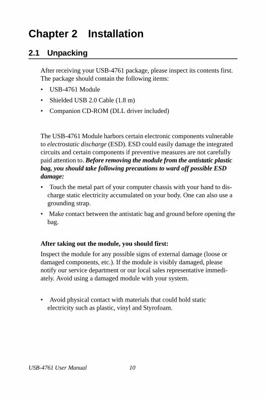
After receiving your USB-4761 package, please inspect its contents first. The package should contain the following items:
• USB-4761 Module
• Shielded USB 2.0 Cable (1.8 m)
• Companion CD-ROM (DLL driver included)
The USB-4761 Module harbors certain electronic components vulnerable to electrostatic discharge (ESD). ESD could easily damage the integrated circuits and certain components if preventive measures are not carefully paid attention to. Before removing the module from the antistatic plastic bag, you should take following precautions to ward off possible ESD damage: • Touch the metal part of your computer chassis with your hand to dis-
charge static electricity accumulated on your body. One can also use a grounding strap.
• Make contact between the antistatic bag and ground before opening the bag.
After taking out the module, you should first: Inspect the module for any possible signs of external damage (loose or damaged components, etc.). If the module is visibly damaged, please notify our service department or our local sales representative immedi- ately. Avoid using a damaged module with your system.
• Avoid physical contact with materials that could hold static electricity such as plastic, vinyl and Styrofoam.
USB-4761 User Manual 10
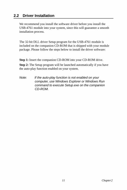
2.2 Driver Installation
We recommend you install the software driver before you install the USB-4761 module into your system, since this will guarantee a smooth installation process.
The 32-bit DLL driver Setup program for the USB-4761 module is included on the companion CD-ROM that is shipped with your module package. Please follow the steps below to install the driver software:
Step 1: Insert the companion CD-ROM into your CD-ROM drive. Step 2: The Setup program will be launched automatically if you have the auto-play function enabled on your system.
Note: If the auto-play function is not enabled on your
computer, use Windows Explorer or Windows Run command to execute Setup.exe on the companion CD-ROM.
11 Chapter 2
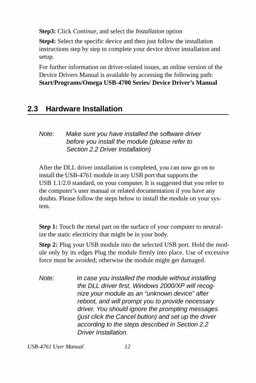
Step3: Click Continue, and select the Installation option Step4: Select the specific device and then just follow the installation instructions step by step to complete your device driver installation and setup. For further information on driver-related issues, an online version of the Device Drivers Manual is available by accessing the following path: Start/Programs/Omega USB-4700 Series/ Device Driver’s Manual
2.3 Hardware Installation
Note: Make sure you have installed the software driver before you install the module (please refer to Section 2.2 Driver Installation)
After the DLL driver installation is completed, you can now go on to install the USB-4761 module in any USB port that supports the USB 1.1/2.0 standard, on your computer. It is suggested that you refer to the computer’s user manual or related documentation if you have any doubts. Please follow the steps below to install the module on your sys- tem.
Step 1: Touch the metal part on the surface of your computer to neutral- ize the static electricity that might be in your body. Step 2: Plug your USB module into the selected USB port. Hold the mod- ule only by its edges Plug the module firmly into place. Use of excessive force must be avoided; otherwise the module might get damaged.
Note: In case you installed the module without installing
the DLL driver first, Windows 2000/XP will recog- nize your module as an “unknown device” after reboot, and will prompt you to provide necessary driver. You should ignore the prompting messages (just click the Cancel button) and set up the driver according to the steps described in Section 2.2 Driver Installation.
USB-4761 User Manual 12
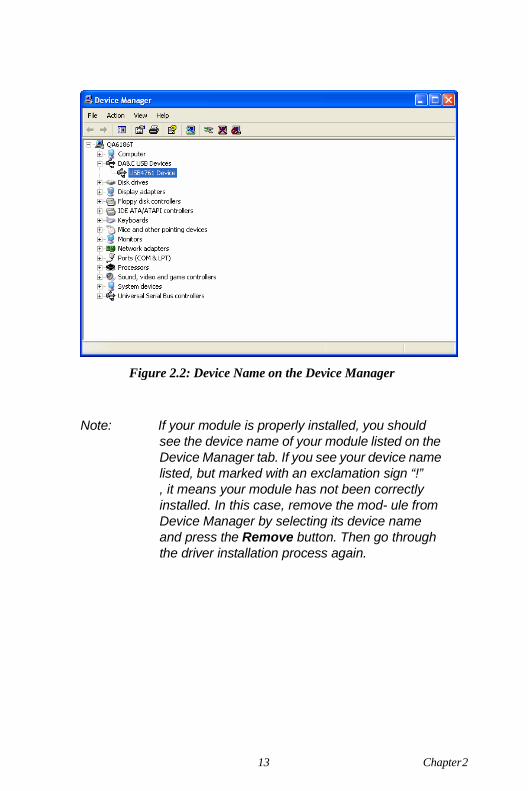
Figure 2.2: Device Name on the Device Manager
Note: If your module is properly installed, you should see the device name of your module listed on the Device Manager tab. If you see your device name listed, but marked with an exclamation sign “!” , it means your module has not been correctly installed. In this case, remove the mod- ule from Device Manager by selecting its device name and press the Remove button. Then go through the driver installation process again.
13 Chapter 2
After your module is properly installed with your system, you can now configure your device using the Device Manager that has itself already been installed on your system during driver setup. A complete device installation procedure should include device setup, configuration and testing. The following sections will guide you through the Setup, Configuration and Testing of your device.
2.4 Device Setup & Configuration
Device Manager is a utility that allows you to set up, configure and test your devices, and later stores your settings in the system registry. These settings will be used when you call the APIs of 32-bit DLL drivers.
2.4.1 Setting Up the Device Step 1: To complete the device setup and configuration procedures, you must first install the device along with its driver. (Please refer to the previous section of Chapter 2 for detailed installation instructions).
USB-4761 User Manual 14
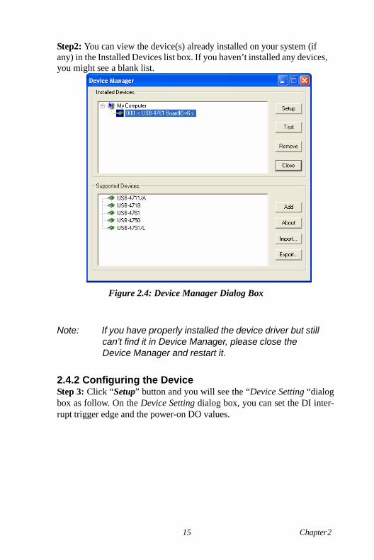
Step2: You can view the device(s) already installed on your system (if any) in the Installed Devices list box. If you haven’t installed any devices, you might see a blank list.
Figure 2.4: Device Manager Dialog Box
Note: If you have properly installed the device driver but still can’t find it in Device Manager, please close the Device Manager and restart it.
2.4.2 Configuring the Device Step 3: Click “Setup” button and you will see the “Device Setting “dialog box as follow. On the Device Setting dialog box, you can set the DI inter- rupt trigger edge and the power-on DO values.
15 Chapter 2
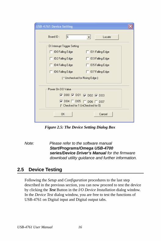
Figure 2.5: The Device Setting Dialog Box
Note: Please refer to the software manual Start/Programs/Omega USB-4700 series/Device Driver’s Manual for the firmware download utility guidance and further information.
2.5 Device Testing
Following the Setup and Configuration procedures to the last step described in the previous section, you can now proceed to test the device by clicking the Test Button in the I/O Device Installation dialog window. In the Device Test dialog window, you are free to test the functions of USB-4761 on Digital input and Digital output tabs.
USB-4761 User Manual 16
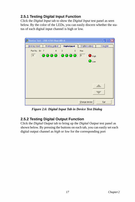
2.5.1 Testing Digital Input Function Click the Digital Input tab to show the Digital Input test panel as seen below. By the color of the LEDs, you can easily discern whether the sta- tus of each digital input channel is high or low.
Figure 2.6: Digital Input Tab in Device Test Dialog
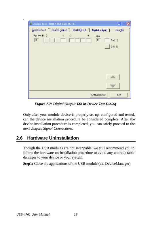
2.5.2 Testing Digital Output Function Click the Digital Output tab to bring up the Digital Output test panel as shown below. By pressing the buttons on each tab, you can easily set each digital output channel as high or low for the corresponding port
17 Chapter 2
.
Figure 2.7: Digital Output Tab in Device Test Dialog
Only after your module device is properly set up, configured and tested, can the device installation procedure be considered complete. After the device installation procedure is completed, you can safely proceed to the next chapter, Signal Connections.
2.6 Hardware Uninstallation
Though the USB modules are hot swappable, we still recommend you to follow the hardware un-installation procedure to avoid any unpredictable damages to your device or your system.
Step1: Close the applications of the USB module (ex. DeviceManager).
USB-4761 User Manual 18
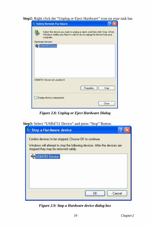
Step2: Right click the “Unplug or Eject Hardware” icon on your task bar.
Figure 2.8: Unplug or Eject Hardware Dialog
Step3: Select “USB4711 Device” and press “Stop” Button.
Figure 2.9: Stop a Hardware device dialog box
19 Chapter 2
Step4: Unplug your USB device from the USB port.
Note: Please make sure that you have closed the application programs before unplugging the USB device, otherwise some unexpected system errors or damages may hap- pen.
USB-4761 User Manual 20
3 2
Signal Connections
This chapter provides useful informa- tion on how to connect input and output signals to the USB-4761 via the I/O connectors..
Sections include:
• Overview
• I/O Connectors
• Field Wiring Considerations
Chapter 3 Signal Connections 3.1 Overview
Maintaining good signal connections is one of the most important factors in ensuring that your application system is sending and receiving data correctly. A good signal connection can avoid unnecessary and costly damage to your PC and other hardware devices.
3.2 I/O Connectors
USB-4761 is equipped with plug-in screw-terminal connectors that facilitate connection to the module without terminal boards or cables.
3.2.1 Pin Assignment Figure 3.1 on next page shows the pin assignments for the five 10-pin I/O connectors on USB-4761.
USB-4761 User Manual 22
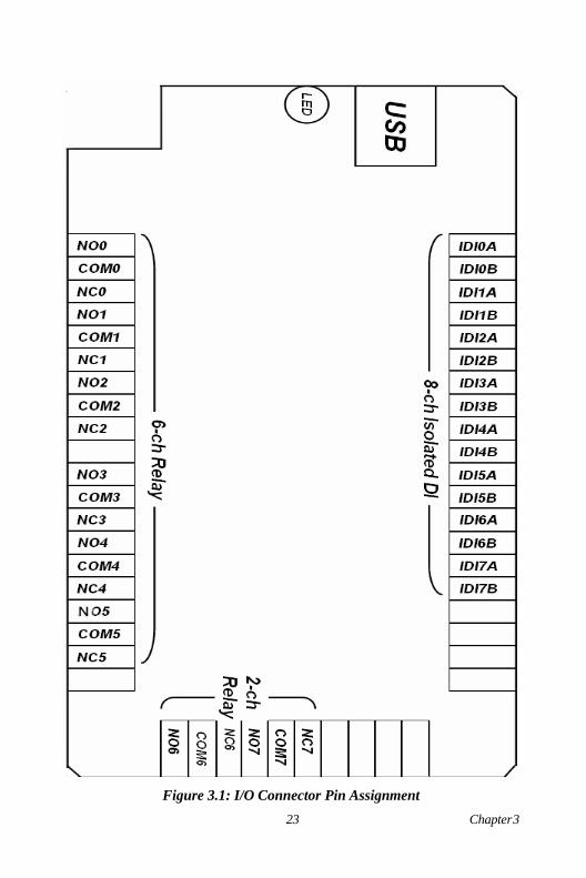
Figure 3.1: I/O Connector Pin Assignment
23 Chapter 3
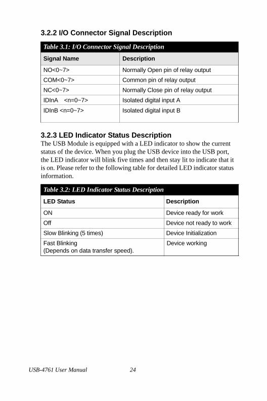
3.2.2 I/O Connector Signal Description
Table 3.1: I/O Connector Signal Description
Signal Name Description
NO<0~7> Normally Open pin of relay output COM<0~7> Common pin of relay output
NC<0~7> Normally Close pin of relay output
IDInA <n=0~7> Isolated digital input A
IDInB <n=0~7> Isolated digital input B
3.2.3 LED Indicator Status Description The USB Module is equipped with a LED indicator to show the current status of the device. When you plug the USB device into the USB port, the LED indicator will blink five times and then stay lit to indicate that it is on. Please refer to the following table for detailed LED indicator status information.
Table 3.2: LED Indicator Status Description
LED Status Description
ON Device ready for work
Off Device not ready to work
Slow Blinking (5 times) Device Initialization
Fast Blinking (Depends on data transfer speed).
Device working
USB-4761 User Manual 24
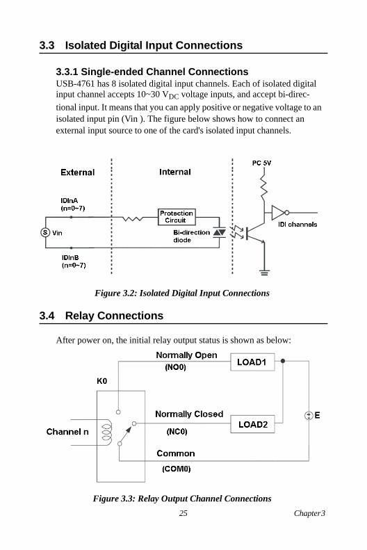
3.3 Isolated Digital Input Connections
3.3.1 Single-ended Channel Connections USB-4761 has 8 isolated digital input channels. Each of isolated digital input channel accepts 10~30 VDC voltage inputs, and accept bi-direc- tional input. It means that you can apply positive or negative voltage to an isolated input pin (Vin ). The figure below shows how to connect an external input source to one of the card's isolated input channels.
Figure 3.2: Isolated Digital Input Connections 3.4 Relay Connections
After power on, the initial relay output status is shown as below:
Figure 3.3: Relay Output Channel Connections
25 Chapter 3
3.5 Field Wiring Considerations
• When you use USB-4761 to acquire data from outside, noises in the environment might significantly affect the accuracy of your measure- ments if due cautions are not taken. The following measures will be helpful to reduce possible interference running signal wires between signal sources and the USB-4761.
• The signal cables must be kept away from strong electromagnetic sources such as power lines, large electric motors, circuit breakers or welding machines, since they may cause strong electromagnetic inter- ference. Keep the analog signal cables away from any video monitor, since it can significantly affect a data acquisition system.
• If the cable travels through an area with significant electromagnetic interference, you should adopt individually shielded, twisted-pair wires as the analog input cable. This type of cable has its signal wires twisted together and shielded with a metal mesh. The metal mesh should only be connected to one point at the signal source ground.
• Avoid running the signal cables through any conduit that might have power lines in it.
• If you have to place your signal cable parallel to a power line that has a high voltage or high current running through it, try to keep a safe dis- tance between them. Or place the signal cable in a right angle to the power line to minimize the undesirable effect.
USB-4761 User Manual 26

A 2
Specifications
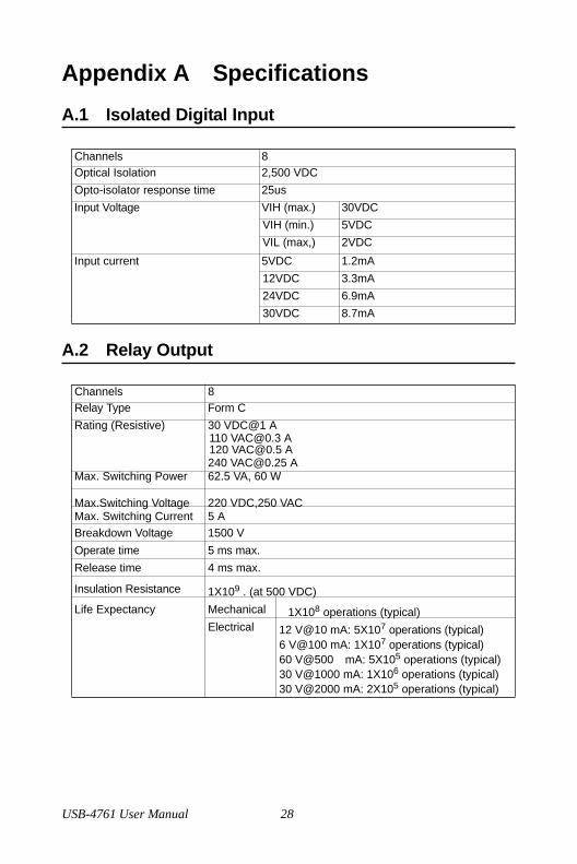
Appendix A Specifications A.1 Isolated Digital Input
Channels 8 Optical Isolation 2,500 VDC Opto-isolator response time 25us Input Voltage VIH (max.) 30VDC
VIH (min.) 5VDC VIL (max,) 2VDC
Input current 5VDC 1.2mA 12VDC 3.3mA 24VDC 6.9mA 30VDC 8.7mA
A.2 Relay Output
Channels 8 Relay Type Form C Rating (Resistive) 30 VDC@1 A
110 [email protected] A 120 [email protected] A 240 [email protected] A
Max. Switching Power 62.5 VA, 60 W
Max.Switching Voltage 220 VDC,250 VAC Max. Switching Current 5 A Breakdown Voltage 1500 V Operate time 5 ms max. Release time 4 ms max.
Insulation Resistance 1X10⁹ . (at 500 VDC)
Life Expectancy Mechanical 1X10⁸ operations (typical) Electrical 12 V@10 mA: 5X10⁷ operations (typical)
6 V@100 mA: 1X10⁷ operations (typical) 60 V@500 mA: 5X10⁵ operations (typical) 30 V@1000 mA: 1X10⁶ operations (typical) 30 V@2000 mA: 2X10⁵ operations (typical)
USB-4761 User Manual 28
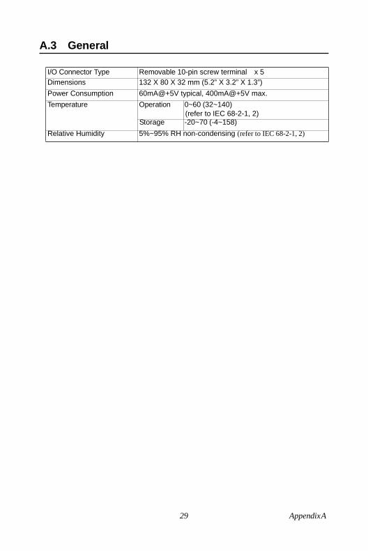
A.3 General
I/O Connector Type Removable 10-pin screw terminal x 5 Dimensions 132 X 80 X 32 mm (5.2” X 3.2” X 1.3”) Power Consumption 60mA@+5V typical, 400mA@+5V max. Temperature Operation 0~60 (32~140)
(refer to IEC 68-2-1, 2) Storage -20~70 (-4~158)
Relative Humidity 5%~95% RH non-condensing (refer to IEC 68-2-1, 2)
29 Appendix A

USB-4761 User Manual 30

B 2
Function Block
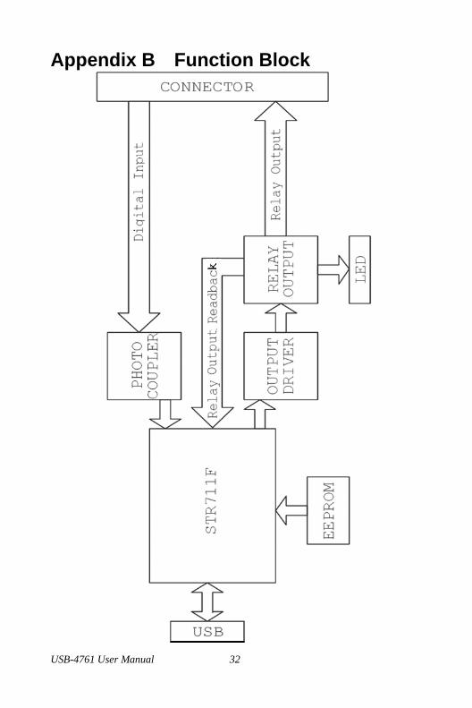
Appendix B Function Block
USB-4761 User Manual 32
WARRANTY/DISCLAIMEROMEGA ENGINEERING, INC. warrants this unit to be free of defects in materials andworkmanship for a period of 13 months from date of purchase. OMEGA’s WARRANTY adds anadditional one (1) month grace period to the normal one (1) year product warranty to coverhandling and shipping time. This ensures that OMEGA’s customers receive maximumcoverage on each product.
If the unit malfunctions, it must be returned to the factory for evaluation. OMEGA’s CustomerService Department will issue an Authorized Return (AR) number immediately upon phone orwritten request. Upon examination by OMEGA, if the unit is found to be defective, it will berepaired or replaced at no charge. OMEGA’s WARRANTY does not apply to defects resultingfrom any action of the purchaser, including but not limited to mishandling, improper interfacing,operation outside of design limits, improper repair, or unauthorized modification. This WARRANTY is VOID if the unit shows evidence of having been tampered with or shows evidenceof having been damaged as a result of excessive corrosion; or current, heat, moisture or vibra-tion; improper specification; misapplication; misuse or other operating conditions outside ofOMEGA’s control. Components in which wear is not warranted, include but are not limited tocontact points, fuses, and triacs.
OMEGA is pleased to offer suggestions on the use of its various products. However, OMEGA neither assumes responsibility for any omissions or errors nor assumes liabilityfor any damages that result from the use of its products in accordance with informationprovided by OMEGA, either verbal or written. OMEGA warrants only that the parts manufactured by the company will be as specified and free of defects. OMEGA MAKESNO OTHER WARRANTIES OR REPRESENTATIONS OF ANY KIND WHATSOEVER,EXPRESSED OR IMPLIED, EXCEPT THAT OF TITLE, AND ALL IMPLIED WARRANTIESINCLUDING ANY WARRANTY OF MERCHANTABILITY AND FITNESS FOR A PARTICULARPURPOSE ARE HEREBY DISCLAIMED. LIMITATION OF LIABILITY: The remedies of pur-chaser set forth herein are exclusive, and the total liability of OMEGA with respect to thisorder, whether based on contract, warranty, negligence, indemnification, strict liability orotherwise, shall not exceed the purchase price of the component upon which liability isbased. In no event shall OMEGA be liable for consequential, incidental or special damages.
CONDITIONS: Equipment sold by OMEGA is not intended to be used, nor shall it be used: (1) asa “Basic Component” under 10 CFR 21 (NRC), used in or with any nuclear installation or activity;or (2) in medical applications or used on humans. Should any Product(s) be used in or with anynuclear installation or activity, medical application, used on humans, or misused in any way,OMEGA assumes no responsibility as set forth in our basic WARRANTY/DISCLAIMER language,and, additionally, purchaser will indemnify OMEGA and hold OMEGA harmless from any liabilityor damage whatsoever arising out of the use of the Product(s) in such a manner.
RETURN REQUESTS/INQUIRIESDirect all warranty and repair requests/inquiries to the OMEGA Customer Service Department.BEFORE RETURNING ANY PRODUCT(S) TO OMEGA, PURCHASER MUST OBTAIN ANAUTHORIZED RETURN (AR) NUMBER FROM OMEGA’S CUSTOMER SERVICE DEPARTMENT(IN ORDER TO AVOID PROCESSING DELAYS). The assigned AR number should then bemarked on the outside of the return package and on any correspondence.The purchaser is responsible for shipping charges, freight, insurance and proper packaging toprevent breakage in transit.
FOR WARRANTY RETURNS, please havethe following information available BEFORE contacting OMEGA:1. Purchase Order number under which
the product was PURCHASED,2. Model and serial number of the product
under warranty, and3. Repair instructions and/or specific
problems relative to the product.
FOR NON-WARRANTY REPAIRS, consultOMEGA for current repair charges. Have thefollowing information available BEFORE contacting OMEGA:1. Purchase Order number to cover the COST
of the repair,2. Model and serial number of the product, and3. Repair instructions and/or specific problems
relative to the product.
OMEGA’s policy is to make running changes, not model changes, whenever an improvement is possible. This affords our customers the latest in technology and engineering.OMEGA is a registered trademark of OMEGA ENGINEERING, INC.© Copyright 2007 OMEGA ENGINEERING, INC. All rights reserved. This document may not be copied, photocopied,reproduced, translated, or reduced to any electronic medium or machine-readable form, in whole or in part, withoutthe prior written consent of OMEGA ENGINEERING, INC.

Where Do I Find Everything I Need for Process Measurement and Control?
OMEGA…Of Course!Shop online at omega.com
TEMPERATURE�� Thermocouple, RTD & Thermistor Probes, Connectors, Panels & Assemblies�� Wire: Thermocouple, RTD & Thermistor�� Calibrators & Ice Point References�� Recorders, Controllers & Process Monitors�� Infrared Pyrometers
PRESSURE, STRAIN AND FORCE�� Transducers & Strain Gages�� Load Cells & Pressure Gages�� Displacement Transducers�� Instrumentation & Accessories
FLOW/LEVEL�� Rotameters, Gas Mass Flowmeters & Flow Computers�� Air Velocity Indicators�� Turbine/Paddlewheel Systems�� Totalizers & Batch Controllers
pH/CONDUCTIVITY�� pH Electrodes, Testers & Accessories�� Benchtop/Laboratory Meters�� Controllers, Calibrators, Simulators & Pumps�� Industrial pH & Conductivity Equipment
DATA ACQUISITION�� Data Acquisition & Engineering Software�� Communications-Based Acquisition Systems�� Plug-in Cards for Apple, IBM & Compatibles�� Datalogging Systems�� Recorders, Printers & Plotters
HEATERS�� Heating Cable�� Cartridge & Strip Heaters�� Immersion & Band Heaters�� Flexible Heaters�� Laboratory Heaters
ENVIRONMENTALMONITORING AND CONTROL�� Metering & Control Instrumentation�� Refractometers�� Pumps & Tubing�� Air, Soil & Water Monitors�� Industrial Water & Wastewater Treatment�� pH, Conductivity & Dissolved Oxygen Instruments M4572/0907