Embed Size (px)
Citation preview

USAMADE IN User’s Guide
www.omega.com e-mail: [email protected]
For latest product manualswww.omegamanual.info
®
®
Shop on line at
Barometric Pressure+ Temperature
Pressure/Temp
Main Menu
http://192.168.1.200
Pressure/Temp
(1 Hour/Div)
1 Day
1 Day
1 Week1 Month1 Year
1 Minute1 Hour
Mon Jul 24 09:42:10 PST 2006
32
9/Div
122
400
80/Div
1200
Temperature 78.3 PressureArchives_Inactive 1000.3F
Tues Jul 25 08:42:10 PST 2006
Alarm SP1(above)=0095.0 F Alarm SP2(below)=0070.0 F
hPa

It is the policy of OMEGA to comply with all worldwide safety and EMC/EMI regulations that apply. OMEGA is constantly pursuing certification of its products to the European New Approach Directives. OMEGA will add the CE markto every appropriate device upon certification.
The information contained in this document is believed to be correct, but OMEGA Engineering, Inc. accepts no liability for anyerrors it contains, and reserves the right to alter specifications without notice.WARNING: These products are not designed for use in, and should not be used for, patient-connected applications.
!This device is marked with the international caution symbol. It is important to read the Setup Guide before installing orcommissioning this device as the guide contains important information relating to safety and EMC.
Servicing North America:
USA:SS One Omega Drive, P.O. Box 4047ISO 9001 CertifiedS Stamford CT 06907-0047SS TEL: (203) 359-1660SS FAX: (203) 359-7700SS e-mail: [email protected]
Canada:: S 976 BergarSS Laval (Quebec) H7L 5A1SS TEL: (514) 856-6928SS FAX: (514) 856-6886SS e-mail: [email protected]
For immediate technical or application assistance:
USA and Canada:S Sales Service: 1-800-826-6342 / 1-800-TC-OMEGA®
SS Customer Service: 1-800-622-2378 / 1-800-622-BEST®
SS Engineering Service: 1-800-872-9436 / 1-800-USA-WHEN®
Mexico and S TEL: (001)800-TC-OMEGA®S FAX: (001) 203-359-7807 Latin American:S En Español: (001) 203-359-7803SSS e-mail: [email protected]
Servicing Europe:
Czech Republic:S Frystatska 184, 733 01 KarvináSS TEL: +420 59 6311899SS FAX: +420 59 6311114SS e-mail: [email protected]
Germany/Austria:S Daimlerstrasse 26, D-75392 Deckenpfronn, GermanySS TEL: +49 7056 9398-0SS FAX: +49 7056 9398-29SS Toll Free in Germany: 0800 639 7678SS e-mail: [email protected]
United Kingdom:S One Omega DriveISO 9002 CertifiedS River Bend Technology CentreSS Northbank, Irlam Manchester M44 5BD United Kingdom SS TEL: +44 161 777 6611S FAX: +44 161 777 6622SS Toll Free in England: 0800 488 488SS e-mail: [email protected]
OMEGAnet® On-Line Servicewww.omega.com
Internet [email protected]
®
®
TABLE OF CONTENTSPart 1: Introduction
1.1 Safety and EMC Considerations ........................................................................21.2 Before You Begin ................................................................................................21.3 Description ..........................................................................................................2
Part 2: Hardware2.1 Mounting .............................................................................................................42.2 DIP Switches........................................................................................................42.3 Parts of iServer Unit ...........................................................................................52.4 Disassembly Instruction ....................................................................................62.5 Network Communication Interfaces .................................................................7
2.5.1 10Base-T RJ-45 Pinout .........................................................................72.5.2 10Base-T Crossover Wiring .................................................................7
2.6 Relay Wiring Connections .................................................................................72.7 Running on Battery Power ................................................................................7
Part 3: Network Configuration3.1 Network Protocols .............................................................................................83.2 Ethernet (MAC) Address ....................................................................................83.3 DHCP ...............................................................................................................93.4 DNS ...............................................................................................................93.5 IP Address ...........................................................................................................9
3.5.1 Default IP Address ..............................................................................103.6 Port Number ......................................................................................................10
Part 4: Operations4.0 Testing the Connection.....................................................................................114.1 iCONNECT Software .........................................................................................124.2 Setting a new IP Address over the Network ..................................................134.3 Setup and Operation using the iServer Web Page .......................................14
4.3.1 Read Sensor ........................................................................................154.3.1.1 Java Runtime Environment 1.4 Setup Instructions .............154.3.1.2 Java Runtime Environment 1.5 (5.0) Setup Instructions ....164.3.1.3 Browser Proxy Selection ........................................................16
4.3.2 Adjustable Chart .................................................................................174.3.3 Retrieving Data from Flash ................................................................184.3.4 Access Control ..................................................................................194.3.5 Configuration ......................................................................................204.3.6 Sensor Parameter ...............................................................................26
4.4 Telnet Setup ......................................................................................................274.5 HTTPGET Program............................................................................................27
4.5.1 HTTPGET using Port 1000 .................................................................284.5.2 HTTPGET and ARP to setup Device IP Address .............................29
4.6 ARP Protocol .....................................................................................................304.7 iLOG Software ...................................................................................................314.8 Mail Notifier Software .......................................................................................32
4.8.1 Installation ...........................................................................................324.8.2 Program Options Setup and Configuration ....................................334.8.3 Device Setting Setup and Configuration ..........................................34
Part 5: Specifications .............................................................................................................35Part 6: Factory Preset Values ......................................................................................................36Appendix A Glossary .............................................................................................................37Appendix B IP Address ........................................................................................................38Appendix C IP Netmask .........................................................................................................39Appendix D ASCII Chart .......................................................................................................40
ASCII Chart Control Codes .............................................................................41Part 7: Approvals Information
7.1 Electromagnetic Compatibility (EMC) ............................................................427.2 FCC ..............................................................................................................42
i

LIST OF FIGURES:
Figure 1.1 iServer and iLD Big Display on the Ethernet Network........................3Figure 2.1 Mounting ................................................................................................4Figure 2.2 DIP Switches ...........................................................................................4Figure 2.3 Parts of iServer Unit...............................................................................5Figure 2.4 Opening the Unit ....................................................................................6Figure 2.5 RJ45 Pinout ............................................................................................7Figure 2.6 10Base-T Crossover Cable Wiring .......................................................7Figure 2.7 Relay Connections ................................................................................7Figure 3.1 Labeling ..................................................................................................8Figure 3.2 DIP Switch on Bottom Side of iServer..................................................9Figure 3.3 Telnet Login into the iServer ...............................................................10Figure 4.1 Pinging the iServer from MS-DOS Prompt ........................................11Figure 4.2 Assigning an IP Address using iCONNECT ......................................12Figure 4.3 Accessing the iServer’s Home Page Menu........................................12Figure 4.4 Access Control ...................................................................................13Figure 4.5 iServer Home Page ..............................................................................14Figure 4.6 Login and Administration Password .................................................14Figure 4.7 Read Sensor .........................................................................................15Figure 4.8 Adjustable Chart...................................................................................17Figure 4.9 iFLASH Download Utility .....................................................................18Figure 4.10 Access Control ....................................................................................19Figure 4.11 Configuration ......................................................................................21Figure 4.12 Sensor Parameter ................................................................................26Figure 4.13 Remote End Char .................................................................................26Figure 4.14 ARP Commands and Responses .......................................................30Figure 4.15 iLOG Software Logging Data ..............................................................31Figure 4.16 iServer Mail Notifier Main Window......................................................32Figure 4.17 iServer Mail Notifier Profile Setup ......................................................33Figure 4.18 iServer Mail Notifier Device Setting ...................................................34
LIST OF TABLES:
Table 2.1 Parts of iServer Unit ..............................................................................5
ii
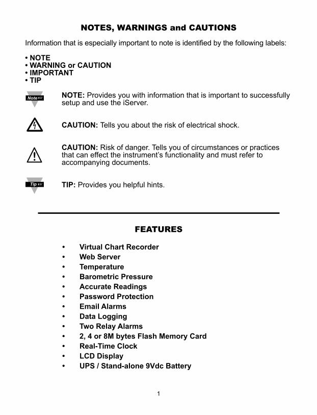
NOTES, WARNINGS and CAUTIONS
Information that is especially important to note is identified by the following labels:
• NOTE • WARNING or CAUTION• IMPORTANT• TIP
NOTE: Provides you with information that is important to successfullysetup and use the iServer.
CAUTION: Tells you about the risk of electrical shock.
CAUTION: Risk of danger. Tells you of circumstances or practicesthat can effect the instrument’s functionality and must refer toaccompanying documents.
TIP: Provides you helpful hints.
FEATURES
• Virtual Chart Recorder• Web Server • Temperature • Barometric Pressure• Accurate Readings • Password Protection • Email Alarms • Data Logging• Two Relay Alarms• 2, 4 or 8M bytes Flash Memory Card• Real-Time Clock• LCD Display• UPS / Stand-alone 9Vdc Battery
1
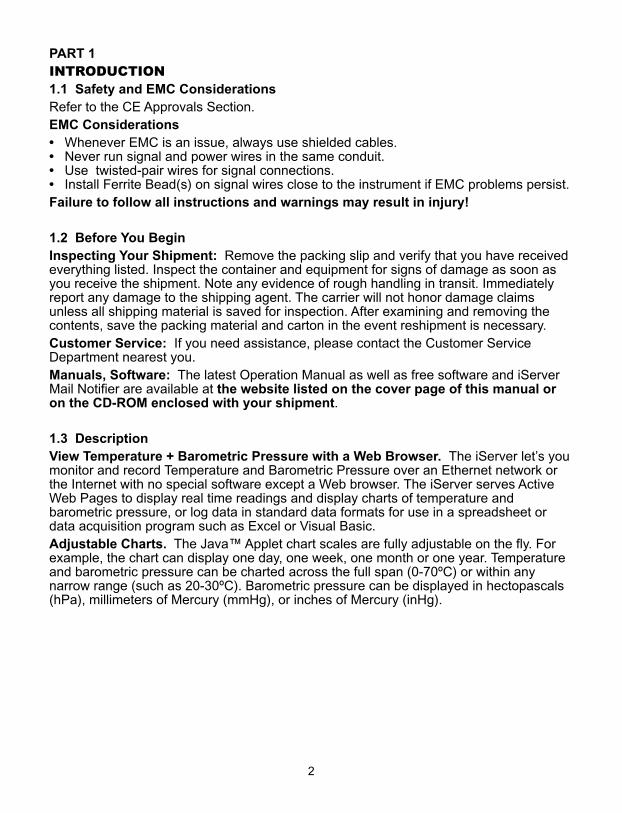
PART 1INTRODUCTION1.1 Safety and EMC ConsiderationsRefer to the CE Approvals Section.EMC Considerations• Whenever EMC is an issue, always use shielded cables.• Never run signal and power wires in the same conduit.• Use twisted-pair wires for signal connections.• Install Ferrite Bead(s) on signal wires close to the instrument if EMC problems persist.Failure to follow all instructions and warnings may result in injury!
1.2 Before You BeginInspecting Your Shipment: Remove the packing slip and verify that you have receivedeverything listed. Inspect the container and equipment for signs of damage as soon asyou receive the shipment. Note any evidence of rough handling in transit. Immediatelyreport any damage to the shipping agent. The carrier will not honor damage claimsunless all shipping material is saved for inspection. After examining and removing thecontents, save the packing material and carton in the event reshipment is necessary.Customer Service: If you need assistance, please contact the Customer ServiceDepartment nearest you.Manuals, Software: The latest Operation Manual as well as free software and iServerMail Notifier are available at the website listed on the cover page of this manual oron the CD-ROM enclosed with your shipment.
1.3 DescriptionView Temperature + Barometric Pressure with a Web Browser. The iServer let’s youmonitor and record Temperature and Barometric Pressure over an Ethernet network orthe Internet with no special software except a Web browser. The iServer serves ActiveWeb Pages to display real time readings and display charts of temperature andbarometric pressure, or log data in standard data formats for use in a spreadsheet ordata acquisition program such as Excel or Visual Basic.Adjustable Charts. The Java™ Applet chart scales are fully adjustable on the fly. Forexample, the chart can display one day, one week, one month or one year. Temperatureand barometric pressure can be charted across the full span (0-70ºC) or within anynarrow range (such as 20-30ºC). Barometric pressure can be displayed in hectopascals(hPa), millimeters of Mercury (mmHg), or inches of Mercury (inHg).
2
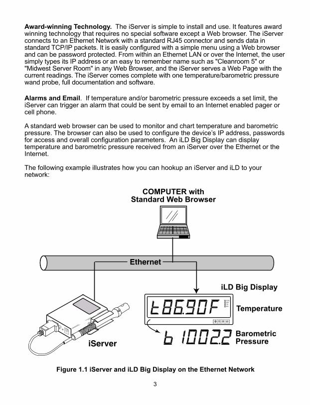
Award-winning Technology. The iServer is simple to install and use. It features awardwinning technology that requires no special software except a Web browser. The iServerconnects to an Ethernet Network with a standard RJ45 connector and sends data instandard TCP/IP packets. It is easily configured with a simple menu using a Web browserand can be password protected. From within an Ethernet LAN or over the Internet, the usersimply types its IP address or an easy to remember name such as "Cleanroom 5" or"Midwest Server Room" in any Web Browser, and the iServer serves a Web Page with thecurrent readings. The iServer comes complete with one temperature/barometric pressurewand probe, full documentation and software.
Alarms and Email. If temperature and/or barometric pressure exceeds a set limit, theiServer can trigger an alarm that could be sent by email to an Internet enabled pager orcell phone.
A standard web browser can be used to monitor and chart temperature and barometricpressure. The browser can also be used to configure the device’s IP address, passwordsfor access and overall configuration parameters. An iLD Big Display can displaytemperature and barometric pressure received from an iServer over the Ethernet or theInternet.
The following example illustrates how you can hookup an iServer and iLD to yournetwork:
Figure 1.1 iServer and iLD Big Display on the Ethernet Network
COMPUTER withStandard Web Browser
COLONTXRX
3
4
PART 2 HARDWARE
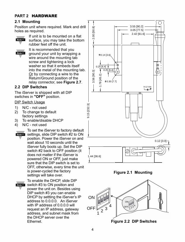
2.1 MountingPosition unit where required. Mark and drillholes as required.
If unit is to be mounted on a flatsurface, you may take the bottomrubber feet off the unit.It is recommended that youground your unit by wrapping awire around the mounting tabscrew and tightening a lockwasher so that it embeds itselfinto the metal of the mounting tab.Or by connecting a wire to theReturn/Ground position of therelay connector, see Figure 2.7.
1
432
OFF
ON
1
432OFF
ON
9-12 Vdc
0.25 [6.4]0.25 [6.4]
1.78
[45.
2]
2.42 [61.6]
3.56
[90.
3]2.
00 [5
0.8]
9.15
[232
.3]
0.14 [3.6]
0.30 [7.7]
3.05 [77.5]3.55 [90.2]
0.12 [3.0]
1.44 [36.6]
Figure 2.1 Mounting
Figure 2.2 DIP Switches
2.2 DIP SwitchesThe iServer is shipped with all DIPswitches in "OFF" position.
DIP Switch Usage
1) N/C - not used2) To change to default
factory settings3) To enable/disable DHCP4) N/C - not used
To set the iServer to factory defaultsettings, slide DIP switch #2 to ONposition. Power the iServer on andwait about 10 seconds until theiServer fully boots up. Set the DIPswitch #2 back to OFF position (itdoes not matter if the iServer ispowered ON or OFF, just makesure that the DIP switch is set toOFF, otherwise, every time the unitis power-cycled the factorysettings will take over.
To enable the DHCP, slide DIPswitch #3 to ON position andpower the unit on. Besides usingDIP switch #3 you can enableDHCP by settting the iServer’s IPaddress to 0.0.0.0. An iServerwith IP address of 0.0.0.0 willrequest an IP address, gatewayaddress, and subnet mask fromthe DHCP server over theEthernet.
5
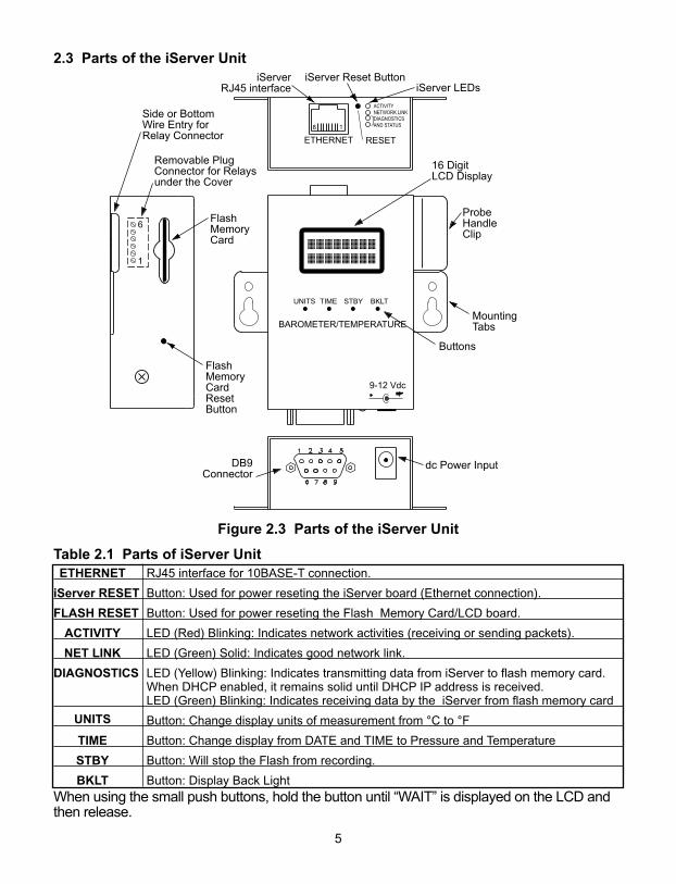
2.3 Parts of the iServer Unit
Figure 2.3 Parts of the iServer Unit
Table 2.1 Parts of iServer UnitETHERNET RJ45 interface for 10BASE-T connection.
iServer RESET Button: Used for power reseting the iServer board (Ethernet connection).
FLASH RESET Button: Used for power reseting the Flash Memory Card/LCD board.
ACTIVITY LED (Red) Blinking: Indicates network activities (receiving or sending packets).
NET LINK LED (Green) Solid: Indicates good network link.
DIAGNOSTICS LED (Yellow) Blinking: Indicates transmitting data from iServer to flash memory card. When DHCP enabled, it remains solid until DHCP IP address is received. LED (Green) Blinking: Indicates receiving data by the iServer from flash memory card
UNITS Button: Change display units of measurement from °C to °F
TIME Button: Change display from DATE and TIME to Pressure and Temperature
STBY Button: Will stop the Flash from recording.
BKLT Button: Display Back LightWhen using the small push buttons, hold the button until “WAIT” is displayed on the LCD andthen release.
9-12 Vdc
ACTIVITYNETWORK LINKDIAGNOSTICSAND STATUS
iServer Reset ButtoniServer LEDs
iServerRJ45 interface
dc Power Input
ProbeHandleClip
BAROMETER/TEMPERATURE
UNITS STBYTIME BKLT
ETHERNET RESET
18
FlashMemoryCardResetButton
FlashMemoryCard
16 DigitLCD Display
Buttons
DB9Connector
Side or BottomWire Entry forRelay Connector
Removable PlugConnector for Relaysunder the Cover
6
1
MountingTabs
6
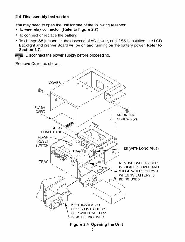
2.4 Disassembly Instruction
You may need to open the unit for one of the following reasons: • To wire relay connector. (Refer to Figure 2.7)
• To connect or replace the battery.
• To change S5 jumper. In the absence of AC power, and if S5 is installed, the LCDBacklight and iServer Board will be on and running on the battery power. Refer toSection 2.7.
Disconnect the power supply before proceeding.
Remove Cover as shown.
Figure 2.4 Opening the Unit
MOUNTINGSCREWS (2)
KEEP INSULATORCOVER ON BATTERYCLIP WHEN BATTERYIS NOT BEING USED
JTAGS5
COVER
TRAY
FLASHCARD
REMOVE BATTERY CLIPINSULATOR COVER ANDSTORE WHERE SHOWNWHEN 9V BATTERY ISBEING USED.
RELAYCONNECTOR
FLASHRESET
SWITCHS5 (WITH LONG PINS)
7
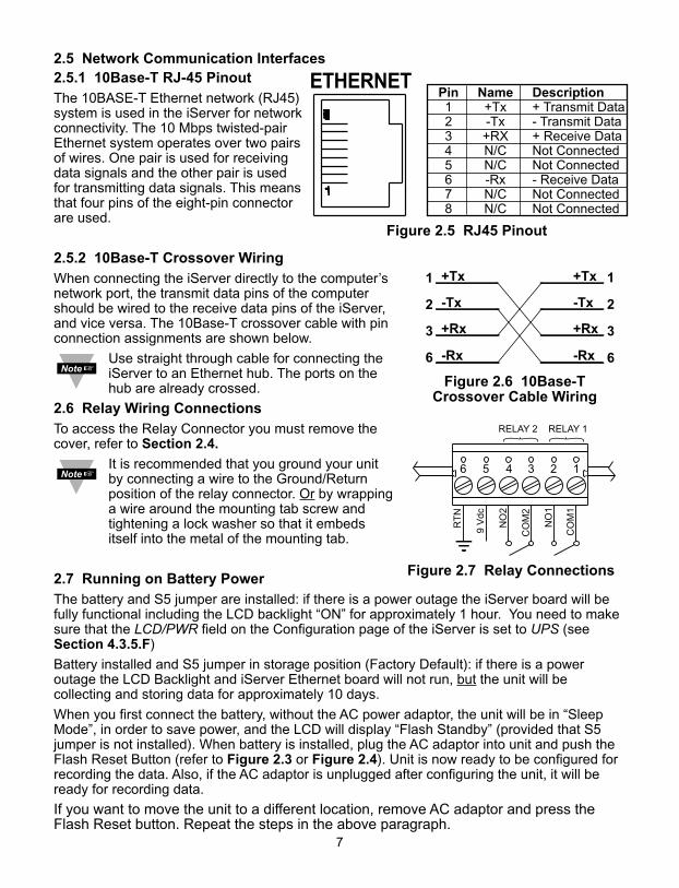
2.5 Network Communication Interfaces2.5.1 10Base-T RJ-45 PinoutThe 10BASE-T Ethernet network (RJ45)system is used in the iServer for networkconnectivity. The 10 Mbps twisted-pairEthernet system operates over two pairsof wires. One pair is used for receivingdata signals and the other pair is usedfor transmitting data signals. This meansthat four pins of the eight-pin connectorare used.
2.5.2 10Base-T Crossover WiringWhen connecting the iServer directly to the computer’snetwork port, the transmit data pins of the computershould be wired to the receive data pins of the iServer,and vice versa. The 10Base-T crossover cable with pinconnection assignments are shown below.
Use straight through cable for connecting theiServer to an Ethernet hub. The ports on thehub are already crossed.
2.6 Relay Wiring ConnectionsTo access the Relay Connector you must remove thecover, refer to Section 2.4.
It is recommended that you ground your unitby connecting a wire to the Ground/Returnposition of the relay connector. Or by wrappinga wire around the mounting tab screw andtightening a lock washer so that it embedsitself into the metal of the mounting tab.
2.7 Running on Battery PowerThe battery and S5 jumper are installed: if there is a power outage the iServer board will befully functional including the LCD backlight “ON” for approximately 1 hour. You need to makesure that the LCD/PWR field on the Configuration page of the iServer is set to UPS (seeSection 4.3.5.F)
Battery installed and S5 jumper in storage position (Factory Default): if there is a poweroutage the LCD Backlight and iServer Ethernet board will not run, but the unit will becollecting and storing data for approximately 10 days.
When you first connect the battery, without the AC power adaptor, the unit will be in “SleepMode”, in order to save power, and the LCD will display “Flash Standby” (provided that S5jumper is not installed). When battery is installed, plug the AC adaptor into unit and push theFlash Reset Button (refer to Figure 2.3 or Figure 2.4). Unit is now ready to be configured forrecording the data. Also, if the AC adaptor is unplugged after configuring the unit, it will beready for recording data.
If you want to move the unit to a different location, remove AC adaptor and press theFlash Reset button. Repeat the steps in the above paragraph.
6 2345 1
NO
1
NO
2
9 V
dc
RT
N
CO
M2
CO
M1
RELAY 2 RELAY 1
Figure 2.7 Relay Connections
Figure 2.6 10Base-TCrossover Cable Wiring
Pin Name Description1 +Tx + Transmit Data2 -Tx - Transmit Data3 +RX + Receive Data4 N/C Not Connected5 N/C Not Connected6 -Rx - Receive Data7 N/C Not Connected8 N/C Not Connected
Figure 2.5 RJ45 Pinout
8
PART 3NETWORK CONFIGURATION
3.1 Network Protocols
The iServer can be connected to the network using standard TCP/IP protocols.It also supports ARP, HTTP (WEB server), DHCP, DNS and Telnet protocols.
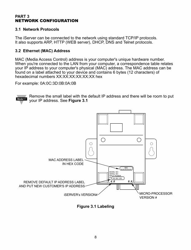
3.2 Ethernet (MAC) Address
MAC (Media Access Control) address is your computer's unique hardware number.When you're connected to the LAN from your computer, a correspondence table relatesyour IP address to your computer's physical (MAC) address. The MAC address can befound on a label attached to your device and contains 6 bytes (12 characters) ofhexadecimal numbers XX:XX:XX:XX:XX:XX hex
For example: 0A:0C:3D:0B:0A:0B
Remove the small label with the default IP address and there will be room to putyour IP address. See Figure 3.1
Figure 3.1 Labeling
9
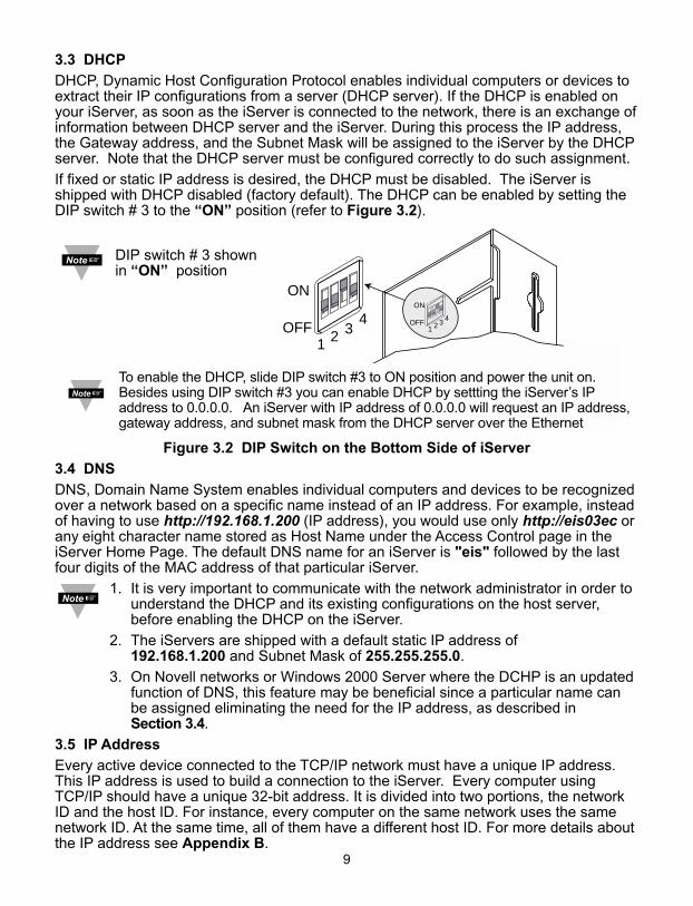
3.3 DHCP
DHCP, Dynamic Host Configuration Protocol enables individual computers or devices toextract their IP configurations from a server (DHCP server). If the DHCP is enabled onyour iServer, as soon as the iServer is connected to the network, there is an exchange ofinformation between DHCP server and the iServer. During this process the IP address,the Gateway address, and the Subnet Mask will be assigned to the iServer by the DHCPserver. Note that the DHCP server must be configured correctly to do such assignment.
If fixed or static IP address is desired, the DHCP must be disabled. The iServer isshipped with DHCP disabled (factory default). The DHCP can be enabled by setting theDIP switch # 3 to the “ON” position (refer to Figure 3.2).
Figure 3.2 DIP Switch on the Bottom Side of iServer
3.4 DNS
DNS, Domain Name System enables individual computers and devices to be recognizedover a network based on a specific name instead of an IP address. For example, insteadof having to use http://192.168.1.200 (IP address), you would use only http://eis03ec orany eight character name stored as Host Name under the Access Control page in theiServer Home Page. The default DNS name for an iServer is "eis" followed by the lastfour digits of the MAC address of that particular iServer.
1. It is very important to communicate with the network administrator in order tounderstand the DHCP and its existing configurations on the host server, before enabling the DHCP on the iServer.
2. The iServers are shipped with a default static IP address of 192.168.1.200 and Subnet Mask of 255.255.255.0.
3. On Novell networks or Windows 2000 Server where the DCHP is an updatedfunction of DNS, this feature may be beneficial since a particular name can be assigned eliminating the need for the IP address, as described in Section 3.4.
3.5 IP Address
Every active device connected to the TCP/IP network must have a unique IP address.This IP address is used to build a connection to the iServer. Every computer usingTCP/IP should have a unique 32-bit address. It is divided into two portions, the networkID and the host ID. For instance, every computer on the same network uses the samenetwork ID. At the same time, all of them have a different host ID. For more details aboutthe IP address see Appendix B.
1
432
OFF
ON
1
432OFF
ON
DIP switch # 3 shownin “ON” position
To enable the DHCP, slide DIP switch #3 to ON position and power the unit on.Besides using DIP switch #3 you can enable DHCP by settting the iServer’s IPaddress to 0.0.0.0. An iServer with IP address of 0.0.0.0 will request an IP address,gateway address, and subnet mask from the DHCP server over the Ethernet
3.5.1 Default IP Address
The iServer is shipped with a default IP address set to 192.168.1.200 and Subnet Maskof 255.255.255.0. If you are going to use a Web browser or Telnet program to accessthe iServer using its default IP address, make sure that the PC from which you’reestablishing the connection has an IP address that is in the same range as the iServer’sIP address (192.168.1.x, where x can be any number from 1 to 254.
Your PC’s IP address cannot be the same as the iServer’s IP address).
You also need to make sure that your PC’s Subnet Mask is 255.255.255.0. This is agood way to access the iServer over the network and make any configuration changesneeded. If 192.168.1.200 is already in use on your network, use an Ethernet crossovercable between your computer and the iServer to change the IP address or any othersettings within the iServer.
3.6 Port Number
All TCP connections are defined by the IP address and a port number. A port number isan internal address that provides an interface between an application running on yourcomputer and the network through the TCP/IP protocol.
There are three default TCP socket port numbers assigned to the iServer:
1. Port (socket) number 1000 when using HTTPGET program.
2. Port (socket) number 2000 when trying to access the sensor (probe) connected to the port of the iServer to receive ASCII data.
3. Port (socket) number 2002 when trying to access the iServer itself for Power Recycling the iServer remotely. This can be done using Windows standard Telnet application.
Power recycling the iServer can also be done through the iServer’s Web Server (seeSection 4.2).
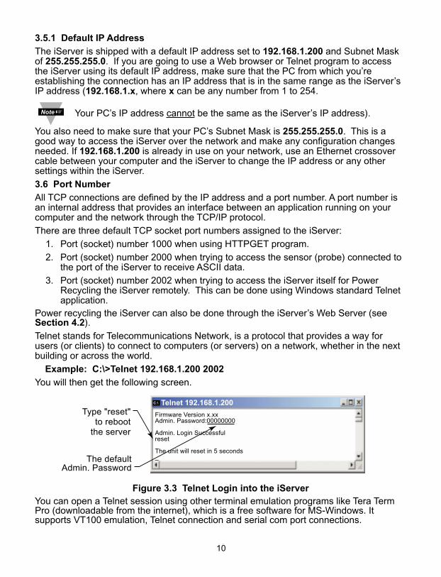
Telnet stands for Telecommunications Network, is a protocol that provides a way forusers (or clients) to connect to computers (or servers) on a network, whether in the nextbuilding or across the world.
Example: C:\>Telnet 192.168.1.200 2002
You will then get the following screen.
Figure 3.3 Telnet Login into the iServerYou can open a Telnet session using other terminal emulation programs like Tera TermPro (downloadable from the internet), which is a free software for MS-Windows. Itsupports VT100 emulation, Telnet connection and serial com port connections.
Firmware Version x.xxAdmin. Password:00000000
Admin. Login Successfulreset
The unit will reset in 5 seconds_The default
Admin. Password
Type "reset"to reboot
the server
C:\ Telnet 192.168.1.200
1010
11
PART 4OPERATIONS
This iServer can be used and configured in several ways, depending on user’spreference and network setup. It can be configured using a Web browser, like Netscapeor Internet Explorer. It can also be configured using NEWPORT’s iCONNECTConfiguration Software.
If DHCP and DNS servers are used, the connection is very simple, no need to find theright IP address or watch for network conflicts, these are all done for you by your networkDHCP and DNS server. All that is left for you to do, is to enable DHCP on the iServer (seeSection 2.2) and use a straight network cable to connect the iServer to a hub and powerit up.
If DHCP is not the preferred method, you can configure your PC’s network connection withan IP address of 192.168.1.x that is in the same range as the iServer’s default IP address(192.168.1.200) and connect to the iServer using a cross-over network cable between yourPC’s network port and the iServer. After you’re done with configuring the iServer, you canalways set your PC back to its original settings.
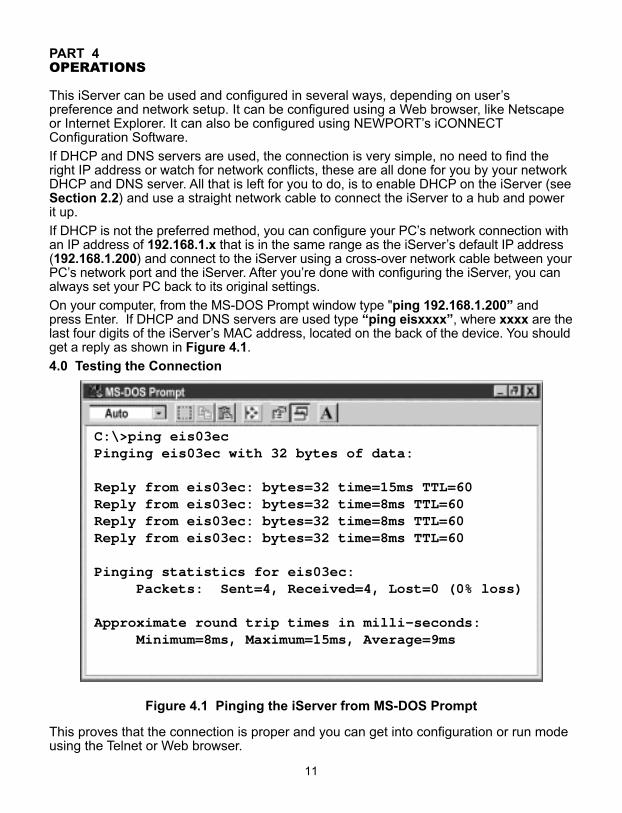
On your computer, from the MS-DOS Prompt window type "ping 192.168.1.200” andpress Enter. If DHCP and DNS servers are used type “ping eisxxxx”, where xxxx are thelast four digits of the iServer’s MAC address, located on the back of the device. You shouldget a reply as shown in Figure 4.1.
4.0 Testing the Connection
Figure 4.1 Pinging the iServer from MS-DOS Prompt
This proves that the connection is proper and you can get into configuration or run modeusing the Telnet or Web browser.
C:\>ping eis03ecPinging eis03ec with 32 bytes of data:
Reply from eis03ec: bytes=32 time=15ms TTL=60Reply from eis03ec: bytes=32 time=8ms TTL=60Reply from eis03ec: bytes=32 time=8ms TTL=60Reply from eis03ec: bytes=32 time=8ms TTL=60
Pinging statistics for eis03ec: Packets: Sent=4, Received=4, Lost=0 (0% loss)
Approximate round trip times in milli-seconds:Minimum=8ms, Maximum=15ms, Average=9ms
12
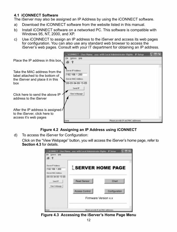
4.1 iCONNECT SoftwareThe iServer may also be assigned an IP Address by using the iCONNECT software.
a) Download the iCONNECT software from the website listed in this manual.
b) Install iCONNECT software on a networked PC. This software is compatible withWindows 95, NT, 2000, and XP.
c) Use iCONNECT to assign an IP address to the iServer and access its web pagesfor configuration. You can also use any standard web browser to access theiServer’s web pages. Consult with your IT department for obtaining an IP address.
Figure 4.2 Assigning an IP Address using iCONNECT
d) To access the iServer for Configuration:
Click on the “View Webpage” button, you will access the iServer’s home page, refer toSection 4.3 for details.
Figure 4.3 Accessing the iServer’s Home Page Menu
Place the IP address in this box
Take the MAC address from thelabel attached to the bottom ofthe iServer and place it in thisbox
Click here to send the above IPaddress to the iServer
After the IP address is assignedto the iServer, click here toaccess it’s web pages
13
4.2 Setting a New IP Address over the Network
Besides using the iCONNECT software, you may use the iServer’s default IP address toaccess it and assign a new IP address to it.
The iServer is shipped with a default IP address of 192.168.1.200 and Subnet Mask of255.255.255.0. You can configure your PC’s Network connection with an IP address thatis in the same range as the iServer’s IP address (192.168.1.x) and connect to the iServerusing a crossover network cable between your PC and the iServer.
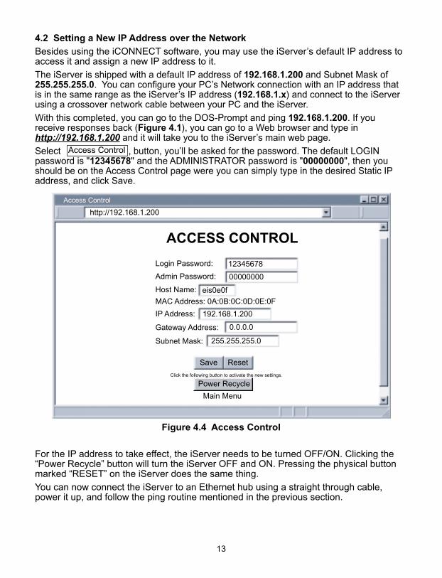
With this completed, you can go to the DOS-Prompt and ping 192.168.1.200. If youreceive responses back (Figure 4.1), you can go to a Web browser and type inhttp://192.168.1.200 and it will take you to the iServer’s main web page.
Select , button, you’ll be asked for the password. The default LOGINpassword is "12345678" and the ADMINISTRATOR password is "00000000", then youshould be on the Access Control page were you can simply type in the desired Static IPaddress, and click Save.
Figure 4.4 Access Control
For the IP address to take effect, the iServer needs to be turned OFF/ON. Clicking the“Power Recycle” button will turn the iServer OFF and ON. Pressing the physical buttonmarked “RESET” on the iServer does the same thing.
You can now connect the iServer to an Ethernet hub using a straight through cable,power it up, and follow the ping routine mentioned in the previous section.
ACCESS CONTROL
Login Password:
Admin Password:
Host Name:
MAC Address: 0A:0B:0C:0D:0E:0F
IP Address:
Gateway Address:
Subnet Mask:
Main Menu
Access Control
Save Reset
0.0.0.0
00000000
12345678
255.255.255.0
192.168.1.200
eis0e0f
http://192.168.1.200
Power Recycle
Access Control
Click the following button to activate the new settings.
14
4.3 Setup and Operation using the iServer Web Page• Start your web browser.• From the browser you type http://eisxxxx using the last four-digits from the MAC
address label located on the device if DHCP and DNS are used. If a static IP address is used, then simply type http://x.x.x.x, where x.x.x.x is the iServer’s IP address.
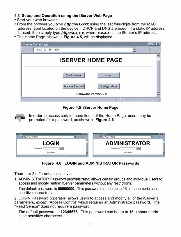
• The Home Page, shown in Figure 4.5, will be displayed.
Figure 4.5 iServer Home Page
In order to access certain menu items of the Home Page, users may beprompted for a password, as shown in Figure 4.6.
Figure 4.6 LOGIN and ADMINISTRATOR Passwords
There are 2 different access levels:
1. ADMINISTRATOR Password (administrator) allows certain groups and individual users to access and modify "entire" iServer parameters without any restrictions.
The default password is 00000000. This password can be up to 16 alphanumeric case-sensitive characters.
2. LOGIN Password (operator) allows users to access and modify all of the iServer’sparameters, except “Access Control” which requires an Administrator password. The"Read Sensor" does not require a password.
The default password is 12345678. This password can be up to 16 alphanumeric case-sensitive characters.
ADMINISTRATOR
ADMINISTRATOR
LOGIN
LOGIN
http://192.168.1.200 http://192.168.1.200
iSERVER HOME PAGE
Firmware Version x.x
http://192.168.1.200
iServer Home Page
Read Sensor
Access Control
Chart
Configuration
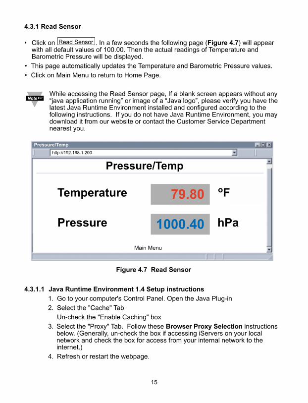
4.3.1 Read Sensor
• Click on . In a few seconds the following page (Figure 4.7) will appearwith all default values of 100.00. Then the actual readings of Temperature andBarometric Pressure will be displayed.
• This page automatically updates the Temperature and Barometric Pressure values.
• Click on Main Menu to return to Home Page.
While accessing the Read Sensor page, If a blank screen appears without any“java application running” or image of a “Java logo”, please verify you have thelatest Java Runtime Environment installed and configured according to thefollowing instructions. If you do not have Java Runtime Environment, you maydownload it from our website or contact the Customer Service Departmentnearest you.
Figure 4.7 Read Sensor
4.3.1.1 Java Runtime Environment 1.4 Setup instructions
1. Go to your computer's Control Panel. Open the Java Plug-in
2. Select the "Cache" Tab
Un-check the "Enable Caching" box
3. Select the "Proxy" Tab. Follow these Browser Proxy Selection instructionsbelow. (Generally, un-check the box if accessing iServers on your localnetwork and check the box for access from your internal network to theinternet.)
4. Refresh or restart the webpage.
http://192.168.1.200
Pressure/Temp
Pressure
Temperature
hPa
F
1000.40
79.80 o
Pressure/Temp
Read Sensor
15
16
4.3.1.2 Java Runtime Environment 1.5 (5.0) Setup instructions1. Go to your computer's Control Panel. Open the Java Plug-in 2. Click on "Settings" & "View Applets" in the "General" tab. 3. Select the "Settings" button on the General Tab
Un-check the "Enable Caching" box. Then close dialog box to show the General Tab again
4. Select the "Network Settings" button on the General Tab.Proceed to the Browser tab. Follow the Browser Proxy Selection instructionsbelow.You should either select the "Use Browser Settings" option or the "DirectConnection" option depending on the network connections between yourcomputer and the iServer product. (Generally, select "Direct Connection" ifaccessing iServers on your local network and select "Use Browser Settings"option for access from your internal network to the internet.)
5. Refresh or restart the webpage. 4.3.1.3 Browser Proxy SelectionAccessing iServer units within your internal network• Usually when the computer and iServer are on an internal network, you will not use Proxy
server access. • You should un-check the "Use Browser Settings" option on the "Proxy" tab.Accessing iServer units using the internet• Often the web browser will use Proxy server access to the internet. In such cases, the
default Java runtime settings on the "Proxy" tab should suffice. The default setting is the"Use Browser Settings" option.
• If the default proxy setting doesn't work, then you may have a situation where the proxysettings of the web browser are incorrect.
Diagnostics: If the web page of the iServer appears, then the HTTP Proxy is working fine. If the data isn't updated on the iServer upon selecting the Read Sensor web page, there may bea problem with access through a winsock proxy server. In such cases your networkadministrator will need to provide the winsock proxy server and port #s. (If the administratorrequires knowledge of the port # required on the iServer, the value is 2003). These values should be entered into the Socks line on the "Proxy" tab (of the Java Plugincontrol panel) or into the "connections" tab on the View,Internet Options dialog and make surethat the Proxy tab shows that the "Use Browser Settings" option is not selected (i.e. when youspecify proxy connections in the Java Plugin control panel. Accessing iServer units over Peer-to-Peer networkA simple peer-to-peer network is setup by disconnecting from the main network (as users willoften do when trying to do initial setup of the iServer) and then connecting the iServer to anothercomputer using a ethernet hub, an ethernet switch, or a Cross-over cable connection. Often when using a peer-to-peer network, the Java plugin and the web browser (such asInternet Explorer) have internet connections configured to connect through proxy servers. Insuch case, you will need to simply assign the final IP address on this peer to peer network andthen view the iServer charts after connecting the iServer into the regular network. Otherwise youcan disable the Java plug-in's "Use Browser Settings" temporarily and then reconfigure the Javaplug-in settings for regular network access after testing the iServer chart access on your peer-to-peer network. The "Use Browser Settings" should not be selected. And the HTTP and Socks proxy entriesshould be blank. Also, setup the internet browser so that proxy servers are disabled.
Java and the Java Coffee Cup Logo are trademarks or registered trademarks of Sun Microsystems, Inc. in the U.S. and other countries."
17
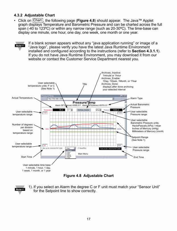
4.3.2 Adjustable Chart
• Click on , the following page (Figure 4.8) should appear. The Java™ Appletgraph displays Temperature and Barometric Pressure and can be charted across the fullspan (-40 to 123ºC) or within any narrow range (such as 20-30ºC). The time-base candisplay one minute, one hour, one day, one week, one month or one year.
If a blank screen appears without any “java application running” or image of a“Java logo”, please verify you have the latest Java Runtime Environmentinstalled and configured according to the instructions (refer to Section 4.3.1.1). If you do not have Java Runtime Environment, you may download it from ourwebsite or contact the Customer Service Department nearest you.
Figure 4.8 Adjustable Chart
1). If you select an Alarm the degree C or F unit must match your “Sensor Unit” for the Setpoint line to show correctly.
Chart
Pressure/Temp
Main Menu
http://192.168.1.200
Pressure/Temp
(1 Hour/Div)
1 Day
1 Day
1 Week1 Month1 Year
1 Minute1 Hour
Mon Jul 24 05:00:00 PST 2006
32
9/Div
122
400
80/Div
1200
Temperature 78.3 PressureArchives_Inactive 1000.3F
Tues Jul 28 19:00:00 PST 2006
Alarm SP1(above)=0095.0 F Alarm SP2(below)=0070.0 F
hPa
User selectable time base1 minute, 1 hour, 1 day,
1 week, 1 month, or 1 year
User selectabletemperature range
User selectabletemperature range
Number of degreesper division
based ontemperature range
Actual Temperature
User selectabletemperature units: F or C
(See Note 1)
Actual BarometricPressure
Alarm Type
Title
Archives_Inactive: 1minute or 1hourArchives_Enable: 1Day, 1Week, 1Month, or 1YearArchives_Done: displays after done archiving your selected interval
Start Time End Time
User selectable Barometric Pressure units: HectoPascals (hPa) / mbar Inches of Mercury (inHg) Millimeters of Mercury (mmHg
User selectablePressure range
User selectablePressure range
Setpoint Range(See Note 1)
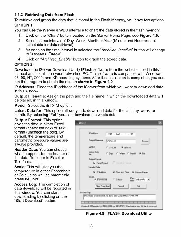
4.3.3 Retrieving Data from FlashTo retrieve and graph the data that is stored in the Flash Memory, you have two options:OPTION 1:You can use the iServer’s WEB interface to chart the data stored in the flash memory.
1. Click on the “Chart” button located on the Server Home Page, see Figure 4.5.2. Select a time interval of Day, Week, Month or Year (Minute and Hour are not
selectable for data retrieval).3. As soon as the time interval is selected the “Archives_Inactive” button will change
to “Archives_Enable”.4. Click on “Archives_Enable” button to graph the stored data.
OPTION 2:Download the iServer Download Utility iFlash software from the website listed in thismanual and install it on your networked PC. This software is compatible with Windows95, 98, NT, 2000, and XP operating systems. After the installation is completed, you canrun the program to obtain the screen shown in Figure 4.9.IP Address: Place the IP address of the iServer from which you want to download data,in this window.Output Filename: Assign the path and the file name in which the downloaded data willbe placed, in this window.Model: Select the iBTX-M option.Latest Data for: This option allows you to download data for the last day, week, ormonth. By selecting “Full” you can download the whole data.Output Format: This optiongives the data in either Excelformat (check the box) or Textformat (uncheck the box). Bydefault, the temperature andbarometric pressure values arealways provided.Header Data: You can choosewhat to appear for the header ofthe data file either in Excel orText format.Scale: This will give you thetemperature in either Fahrenheitor Celsius as well as barometricpressure units..Access Log: The completion ofdata download will be reported inthis window. You can startdownloading by clicking on the“Start Download” button.
18
Figure 4.9 iFLASH Download Utility
19
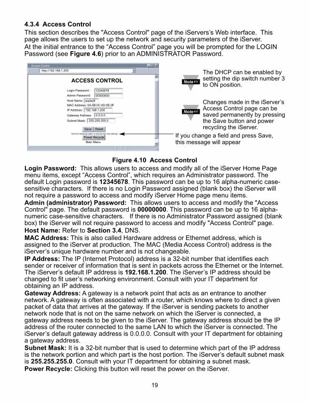
4.3.4 Access ControlThis section describes the "Access Control" page of the iServers’s Web interface. Thispage allows the users to set up the network and security parameters of the iServer. At the initial entrance to the “Access Control” page you will be prompted for the LOGINPassword (see Figure 4.6) prior to an ADMINISTRATOR Password.
Figure 4.10 Access Control Login Password: This allows users to access and modify all of the iServer Home Pagemenu items, except “Access Control”, which requires an Administrator password. Thedefault Login password is 12345678. This password can be up to 16 alpha-numeric case-sensitive characters. If there is no Login Password assigned (blank box) the iServer willnot require a password to access and modify iServer Home page menu items.Admin (administrator) Password: This allows users to access and modify the "AccessControl" page. The default password is 00000000. This password can be up to 16 alpha-numeric case-sensitive characters. If there is no Administrator Password assigned (blankbox) the iServer will not require password to access and modify "Access Control" page. Host Name: Refer to Section 3.4, DNS.MAC Address: This is also called Hardware address or Ethernet address, which isassigned to the iServer at production. The MAC (Media Access Control) address is theiServer’s unique hardware number and is not changeable.IP Address: The IP (Internet Protocol) address is a 32-bit number that identifies eachsender or receiver of information that is sent in packets across the Ethernet or the Internet.The iServer’s default IP address is 192.168.1.200. The iServer’s IP address should bechanged to fit user’s networking environment. Consult with your IT department forobtaining an IP address.Gateway Address: A gateway is a network point that acts as an entrance to anothernetwork. A gateway is often associated with a router, which knows where to direct a givenpacket of data that arrives at the gateway. If the iServer is sending packets to anothernetwork node that is not on the same network on which the iServer is connected, agateway address needs to be given to the iServer. The gateway address should be the IPaddress of the router connected to the same LAN to which the iServer is connected. TheiServer’s default gateway address is 0.0.0.0. Consult with your IT department for obtaininga gateway address. Subnet Mask: It is a 32-bit number that is used to determine which part of the IP addressis the network portion and which part is the host portion. The iServer’s default subnet maskis 255.255.255.0. Consult with your IT department for obtaining a subnet mask.Power Recycle: Clicking this button will reset the power on the iServer.
ACCESS CONTROL
Login Password:
Admin Password:
Host Name:
MAC Address: 0A:0B:0C:0D:0E:0F
IP Address:
Gateway Address:
Subnet Mask:
Main Menu
Access Control
Save Reset
0.0.0.0
00000000
12345678
255.255.255.0
192.168.1.200
eis0e0f
http://192.168.1.200
Power Recycle
The DHCP can be enabled bysetting the dip switch number 3to ON position.
Changes made in the iServer’sAccess Control page can besaved permanently by pressingthe Save button and powerrecycling the iServer.
If you change a field and press Save,this message will appear
Click the following button to activate the new settings.

4.3.5 Configuration
Setting up the Flash Memory Card can be done in the Configuration page. From theHome Page Menu click on to get to the page (see Figure 4.11).
General Description of the Configuration page: There are two general sections “FlashCard Memory” and “Server”. Flash Card Memory consists of the following titles: RealTime Clock (RTC), Title, Alarm Setup, and Flash Recording. Server consists of TerminalServer and Remote Access.
Title and Flash Recording selections can be editted once by selecting “Activation -StartRecord” and after that, no modification will take place unless recording is stopped(the reason for this is to be compliant with the data logging rules). The remainingparameters can be changed during recording as explained below.
There are several scenarios depending on the state of the Flash Card and the Real TimeClock (RTC):
#1) RTC is not set and Flash Card is empty.
All the fields must be updated exactly according to the indicated format, “Adjust RTCOnly” check box must be left unchecked, “Activation” selection must set to“StartRecord” and click the “Update” button. Having done this, it is recommended toselect “Configuration” from “Activation” drop down window, click the “Update” button,set the “Activation” to “Status/RTC/Alarm” and click the “Update” button one moretime to review/verify that the setup took place as it was intended.
#2) RTC is set, and recording is in progress.
The only possible setups are to update “Date” and “Time” of the Real Time Clockalong with checking “Adjust RTC Only” box. Also, alarms can be updated providedthat “Activation” is set to “Status/RTC/Alarm”. Otherwise, the recording has to bestopped by selecting “StopRecord” of the “Activation” drop down window prior tomodifying the Flash Card setup. An alternative way to stop recording is to pushStandby Button (refer to Figure 2.3) of the unit.
#3) RTC is set, recording is stopped, and Flash Card is not empty.
This means that a pre-recorded Flash Card is installed, and by activating the chart thearchived data can be viewed (Refer to Figure 4.8). The chart has the followingselections:
1 Minute, 1 Day, 1 Week, 1 Month, 1 Year
In other words, they are the last specified selection e.g. 1 Day means the last day ofthe recorded data. Having done the selection, the “Archives_Enable” button must beclicked, which will then change to “Archives_Done” and the data will be retrievedaccordingly. Also, the corresponding Start and End dates will reflect the respectivetime duration e.g. refer to Figure 4.8 which is the last 1 Day, the dates are:
02/20/2004 09:42:10 to 02/21/2004 09:42:10.
#4) RTC is not set and the Flash Card is not empty.
This is similiar to item 3) above except that at the power-up the installed Flash Cardwas not empty. Or, the Flash Card Reset Button (refer to Figure 2.3) was pushed.
Configuration
20
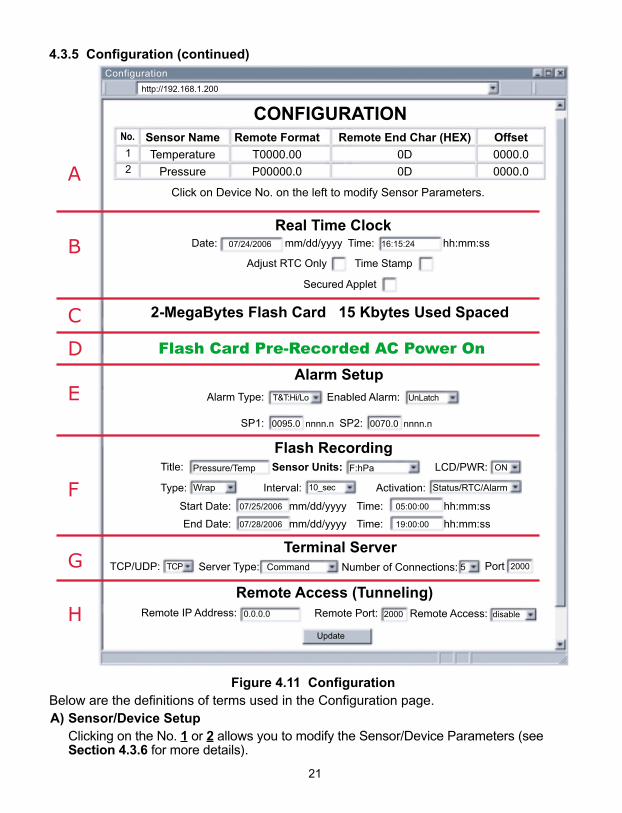
4.3.5 Configuration (continued)
Figure 4.11 ConfigurationBelow are the definitions of terms used in the Configuration page.A) Sensor/Device Setup
Clicking on the No. 1 or 2 allows you to modify the Sensor/Device Parameters (seeSection 4.3.6 for more details).
http://192.168.1.200
Click on Device No. on the left to modify Sensor Parameters.
Sensor Name
Temperature
Pressure
Remote Format
T0000.00
P00000.0
Remote End Char (HEX)
0D
0D
Offset
0000.0
0000.0
07/24/2006
Flash Card Pre-Recorded AC Power On
0070.0 nnnn.n0095.0 nnnn.n
Pressure/Temp F:hPaSensor Units:
07/25/2006
07/28/2006
05:00:00
19:00:00
Status/RTC/AlarmWrap
5Command
21
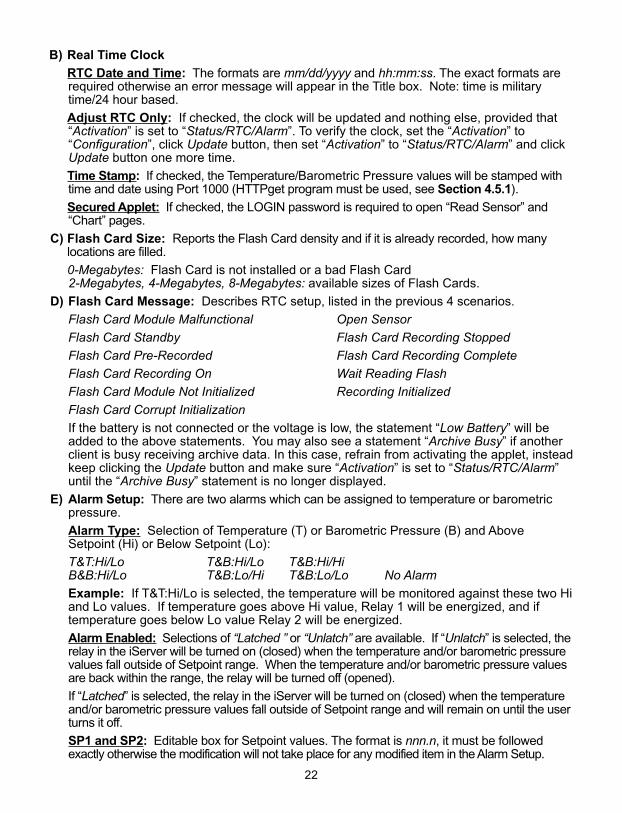
B) Real Time Clock
RTC Date and Time: The formats are mm/dd/yyyy and hh:mm:ss. The exact formats arerequired otherwise an error message will appear in the Title box. Note: time is militarytime/24 hour based.
Adjust RTC Only: If checked, the clock will be updated and nothing else, provided that“Activation” is set to “Status/RTC/Alarm”. To verify the clock, set the “Activation” to“Configuration”, click Update button, then set “Activation” to “Status/RTC/Alarm” and clickUpdate button one more time.
Time Stamp: If checked, the Temperature/Barometric Pressure values will be stamped withtime and date using Port 1000 (HTTPget program must be used, see Section 4.5.1).
Secured Applet: If checked, the LOGIN password is required to open “Read Sensor” and“Chart” pages.
C) Flash Card Size: Reports the Flash Card density and if it is already recorded, how manylocations are filled.
0-Megabytes: Flash Card is not installed or a bad Flash Card2-Megabytes, 4-Megabytes, 8-Megabytes: available sizes of Flash Cards.
D) Flash Card Message: Describes RTC setup, listed in the previous 4 scenarios.
Flash Card Module Malfunctional Open Sensor
Flash Card Standby Flash Card Recording Stopped
Flash Card Pre-Recorded Flash Card Recording Complete
Flash Card Recording On Wait Reading Flash
Flash Card Module Not Initialized Recording Initialized
Flash Card Corrupt Initialization
If the battery is not connected or the voltage is low, the statement “Low Battery” will beadded to the above statements. You may also see a statement “Archive Busy” if anotherclient is busy receiving archive data. In this case, refrain from activating the applet, insteadkeep clicking the Update button and make sure “Activation” is set to “Status/RTC/Alarm”until the “Archive Busy” statement is no longer displayed.
E) Alarm Setup: There are two alarms which can be assigned to temperature or barometricpressure.
Alarm Type: Selection of Temperature (T) or Barometric Pressure (B) and AboveSetpoint (Hi) or Below Setpoint (Lo):
T&T:Hi/Lo T&B:Hi/Lo T&B:Hi/HiB&B:Hi/Lo T&B:Lo/Hi T&B:Lo/Lo No Alarm
Example: If T&T:Hi/Lo is selected, the temperature will be monitored against these two Hiand Lo values. If temperature goes above Hi value, Relay 1 will be energized, and iftemperature goes below Lo value Relay 2 will be energized.
Alarm Enabled: Selections of “Latched ” or “Unlatch” are available. If “Unlatch” is selected, therelay in the iServer will be turned on (closed) when the temperature and/or barometric pressurevalues fall outside of Setpoint range. When the temperature and/or barometric pressure valuesare back within the range, the relay will be turned off (opened).
If “Latched” is selected, the relay in the iServer will be turned on (closed) when the temperatureand/or barometric pressure values fall outside of Setpoint range and will remain on until the userturns it off.
SP1 and SP2: Editable box for Setpoint values. The format is nnn.n, it must be followedexactly otherwise the modification will not take place for any modified item in the Alarm Setup.
22
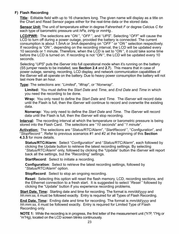
F) Flash Recording
Title: Editable field with up to 16 characters long. The given name will display as a title onthe Chart and Read Sensor pages either for the real-time data or the stored data.
Sensor Unit: The unit of temperature either in degree Fahrenheit F or degree Celcius C foreach type of barometric pressure unit hPa, inHg or mmHg..
LCD/PWR: The selections are “ON ”, “OFF ”, and “UPS”. Selecting “OFF” will cause theLCD to turn off during a power outage, provided the battery is connected. The currentconsumption is about 1.5mA or 3mA depending on “OFF ” or “ON ” selection respectively.If recording is “ON “, depending on the recording interval, the LCD will be updated every10 seconds or 1 minute. Therefore, when the LCD is set to “ON ”, it could take some timebefore the LCD is turned on. If recording is not “ON “, the LCD will be updated every 10seconds.
Selecting “UPS” puts the iServer into full operational mode when it’s running on the battery(S5 jumper needs to be installed, see Section 2.4 and 2.7). This means that in case ofpower outage, sensing, recording, LCD display, and network communication capabilities ofthe iServer will all operate on the battery. Due to heavy power consumption the battery will notlast more than an hour.
Type: The selections are: “Limited”, “Wrap”, or “Nonwrap”.
Limited: You must define the Start Date and Time, and End Date and Time in whichyou need the recording to be done.
Wrap: You only need to define the Start Date and Time. The iServer will record datauntil the Flash is full, then the iServer will continue to record and overwrite the existingdata.
Nonwrap: You only need to define the Start Date and Time. The iServer will recorddata until the Flash is full, then the iServer will stop recording.
Interval: The recording interval at which the temperature or barometric pressure is beingstored into the Flash Card. The selections are “10 seconds“ and “1 minute“.
Activation: The selections are “Status/RTC/Alarm”, “StartRecord ”, “Configuration”, and“StopRecord ”. Refer to previous scenarios #1 and #2 at the beginning of this Section4.3.5 for more details.
Status/RTC/Alarm: Select “Configuration” and “Status/RTC/Alarm”, each followed byclicking the Update button to retrieve the latest recording settings. By selecting“Status/RTC/Alarm” only, followed by clicking the “Update” button the iServer will reportback all the settings, but the “Recording” settings.
StartRecord: Select to initiate a recording.
Configuration: Select to retrieve the latest recording settings, followed by“Status/RTC/Alarm” option.
StopRecord: Select to stop an ongoing recording.
Reset: Selecting this option will reset the flash memory, LCD, recording sections, andthe Ethernet connection to a fresh start. It is suggested to select “Reset ” followed byclicking the “Update” button if you experience recording problems.
Start Date, Time: Starting date and time for recording. The format is mm/dd/yyyy andhh:mm:ss, it must be followed exactly. Entry is required for all Types of Flash Recording.
End Date, Time: Ending date and time for recording. The format is mm/dd/yyyy andhh:mm:ss, it must be followed exactly. Entry is required for Limited Type of FlashRecording only.
NOTE 1: While the recording is in progress, the first letter of the measurement unit (“h”P, “i”Hg or“m”Hg), located on the LCD screen blinks continuously.
23
NOTE 2: Downloading data and recording can not be done at the same time. Whiledownloading data, the writing process to the flash memory will be internally disabled whilethe data is being read from the memory flash. For small amounts of data to be retrieved(1 Day or 1 Week), this is not a significant interruption in the recording data. However, forlarge amounts of data (1 Month or 1 Year) it may take 4 to 8 minutes to download thedata. In “Archives_Enabled “ mode, charting remains static, while data download is takingplace.
NOTE 3: The number of barometric pressure/temperature values that can be recorded dependson the memory flash capacity (2 Mbytes, 4 Mbytes or 8 Mbytes) and number of barometricpressure / temperature values (540,540, 1,081,212 and 2,162,556). The time to fill thememory flash depends on the recording interval time, e.g. 1 minute interval for 4 Mbytes is1,081,212 minutes or 750 days. If the flash is busy sending data to the applet to chart the archive,the iServer will refuse to initiate a call to provide archived data to the second applet until it hasfinished with the first one.
NOTE 4: If there is a loss of power while recording the data, the number of data logged cannot be stored, therefore having restored the power the logged data will be read from FlashMemory and the number of recorded data will be stored for future use. During this processthe LCD will display “Reading Flash”, and if you connect through a web browser theConfiguration page will display “Wait Reading Flash”.
NOTE 5: After you “StartRecord” the flash recording followed by clicking the “Update”button, if you then need to make any changes in the Flash Recording section you musteither select “StopRecord” followed by clicking the “Update” button or push the reset buttonon the side of the iServer and reconfigure the Flash Recording section again.
NOTE 6: If you stop the recording prematurely, when you download the data, you will losethe last 256 bytes of the data that was left in the buffer and was not transferred into the flashcard. Therefore, we strongly suggest downloading the data while the recording is still on and thenstop the recording if desired.
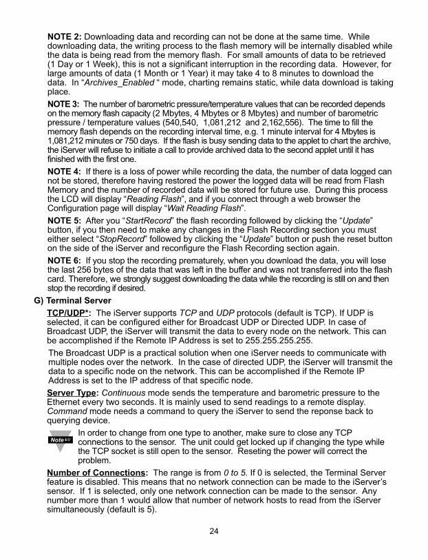
G) Terminal Server
TCP/UDP*: The iServer supports TCP and UDP protocols (default is TCP). If UDP isselected, it can be configured either for Broadcast UDP or Directed UDP. In case ofBroadcast UDP, the iServer will transmit the data to every node on the network. This canbe accomplished if the Remote IP Address is set to 255.255.255.255.
The Broadcast UDP is a practical solution when one iServer needs to communicate withmultiple nodes over the network. In the case of directed UDP, the iServer will transmit thedata to a specific node on the network. This can be accomplished if the Remote IPAddress is set to the IP address of that specific node.
Server Type: Continuous mode sends the temperature and barometric pressure to theEthernet every two seconds. It is mainly used to send readings to a remote display.Command mode needs a command to query the iServer to send the reponse back toquerying device.
In order to change from one type to another, make sure to close any TCPconnections to the sensor. The unit could get locked up if changing the type whilethe TCP socket is still open to the sensor. Reseting the power will correct theproblem.
Number of Connections: The range is from 0 to 5. If 0 is selected, the Terminal Serverfeature is disabled. This means that no network connection can be made to the iServer’ssensor. If 1 is selected, only one network connection can be made to the sensor. Anynumber more than 1 would allow that number of network hosts to read from the iServersimultaneously (default is 5).
24
Port: (default 2000) is the default TCP port number for the port to which the sensor isconnected. Ports 1000 (used for HTTPget, refer to Section 4.5), 2002, 2003, and 2004are reserved for internal use.
Terminal Server usually describes a device that exchanges data betweenEthernet/TCPIP networks and RS-232/RS-485 systems. With this iServer,the data is obtained digitally from the sensor (irrelevant to RS-232 or RS-485interface) and can be accessed from anywhere on the network.
A computer program, such as NEWPORT’s Mail Notifier, OPC Server, iLOG,iFLASH or httpget can send TCP requests and obtain readings using theTerminal Server feature.
H) Remote Access
Remote IP Address: iServer can establish a connection to a remote device (e.g. aniLD Remote Display with an Ethernet iServer embedded board) with this IP.
Remote Port: (default 2000) the remote port number for the connection. Ports 1000(used for HTTPget, refer to Section 4.5), 2002, 2003, and 2004 are reserved forinternal use.
Remote Access:** Remote Access can be enabled and disabled. If enabled, theiServer can send its data to a remote node on the same network (the “Remote IPaddress” and “Remote Port” must be entered).
*TCP/UDP: when UDP mode is selected, Remote Access should be disabledand Remote IP and Port are the UDP remote listening IP and Port. If theRemote IP is set to 255.255.255.255, the UDP packet becomes abroadcasting packet which will allow any device listening to the Remote portto receive the packet.
**If Remote Access is enabled, Terminal Server is automatically disabled.
25
26
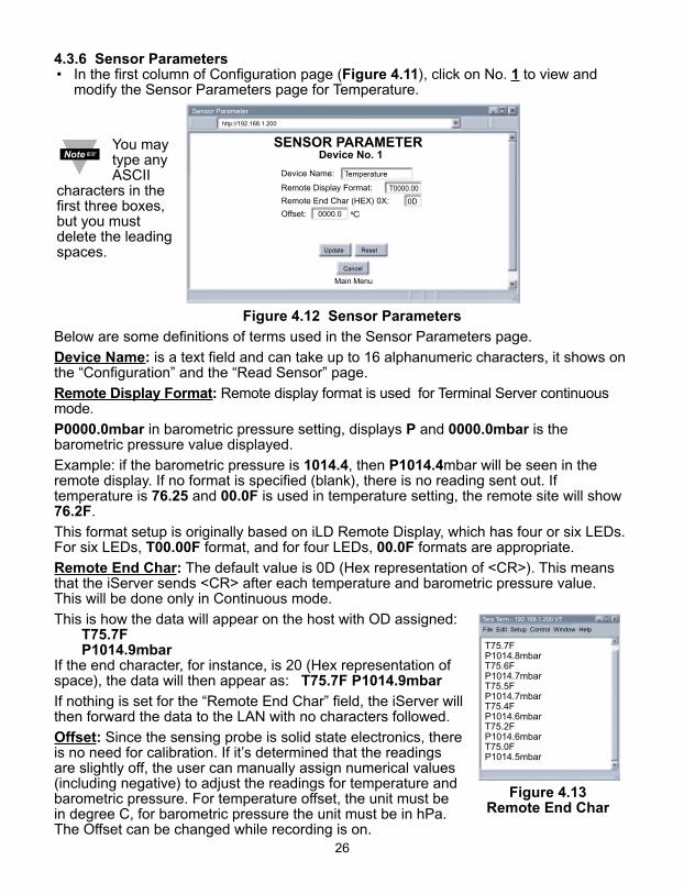
4.3.6 Sensor Parameters• In the first column of Configuration page (Figure 4.11), click on No. 1 to view and
modify the Sensor Parameters page for Temperature.
Figure 4.12 Sensor Parameters
Below are some definitions of terms used in the Sensor Parameters page.
Device Name: is a text field and can take up to 16 alphanumeric characters, it shows onthe “Configuration” and the “Read Sensor” page.
Remote Display Format: Remote display format is used for Terminal Server continuousmode.
P0000.0mbar in barometric pressure setting, displays P and 0000.0mbar is thebarometric pressure value displayed.
Example: if the barometric pressure is 1014.4, then P1014.4mbar will be seen in theremote display. If no format is specified (blank), there is no reading sent out. Iftemperature is 76.25 and 00.0F is used in temperature setting, the remote site will show76.2F.
This format setup is originally based on iLD Remote Display, which has four or six LEDs.For six LEDs, T00.00F format, and for four LEDs, 00.0F formats are appropriate.
Remote End Char: The default value is 0D (Hex representation of <CR>). This meansthat the iServer sends <CR> after each temperature and barometric pressure value.This will be done only in Continuous mode.
This is how the data will appear on the host with OD assigned:T75.7FP1014.9mbar
If the end character, for instance, is 20 (Hex representation ofspace), the data will then appear as: T75.7F P1014.9mbar
If nothing is set for the “Remote End Char” field, the iServer willthen forward the data to the LAN with no characters followed.
Offset: Since the sensing probe is solid state electronics, thereis no need for calibration. If it’s determined that the readingsare slightly off, the user can manually assign numerical values(including negative) to adjust the readings for temperature andbarometric pressure. For temperature offset, the unit must bein degree C, for barometric pressure the unit must be in hPa.The Offset can be changed while recording is on.
SENSOR PARAMETERDevice No. 1
Device Name:
Main Menu
http://192.168.1.200
Sensor Parameter
Update Reset
Temperature
Remote Display Format: T0000.00
Remote End Char (HEX) 0X: 0D
Offset: C 0000.0
Cancel
T75.7FP1014.8mbarT75.6FP1014.7mbarT75.5FP1014.7mbarT75.4FP1014.6mbarT75.2FP1014.6mbarT75.0FP1014.5mbar
Tera Term - 192.168.1.200 VT
File Edit Setup Control Window Help
Figure 4.13 Remote End Char
You maytype anyASCII
characters in thefirst three boxes,but you mustdelete the leadingspaces.
27
4.4 Telnet Setup
Set the Number of Connections to 1-5 other than 0, using telnet simulation programconnect to iServer. In continuous mode, the telnet teminal will receive continuousmessages from the iServer. In command mode, the command can be sent to query theiServer and get a response back. Refer to Figure 3.3
Send remote reset: Telnet port 2002 will bring a terminal for admin password. After typingthe password and following with the end character, the message Admin. LoginSuccessful will be showed on the terminal. Now type "reset" following with returncharacter to reset the iServer. If no character is received within 20 seconds, the terminalwill be closed automatically.
Initiating the archive chart while Telnet is active will halt Telnet until the archivechart is done.
4.5 HTTPGET Program
The Httpget software is used to send a single HTTP or TCP request to an iServerproduct. In contrast, the telnet or Hyperterminal programs allow a continuousconnection with multiple requests to be sent to the iServer product.
Generally httpget is used for simply programming an IP address to the iServer or forquickly obtaining a reading of from a device.
The iServer product must be configured from the configuration web page so that the"Server Type" value is set to "Command" (This is positioned under the heading ofTerminal Server). Also the Number of Connections may need to be set to "0" to enablePort 1000 (Port 1000 is for access in a non-standard terminal mode). To use Port 2000access (where "2000" is the value stored in "Port"), the Number of Connections shouldbe set to "2" for general usage. The value of 2 can later be changed to a value from 1 to5 depending on needs for secure access or fault tolerance.
Whenever Terminal Server service (using Port 2000 by default) is required, the Numberof Connections must be set to a value from 1 to 5. The Terminal Server mode is therecommended mode for the most reliable connection when operating with NEWPORTsoftware or with other programs supporting TCPIP communications. The Port 1000access can be used with NEWPORT software and may be needed with some iServerproducts when you need to view readings from the web page while simultaneouslycollecting data through TCPIP communications.
28
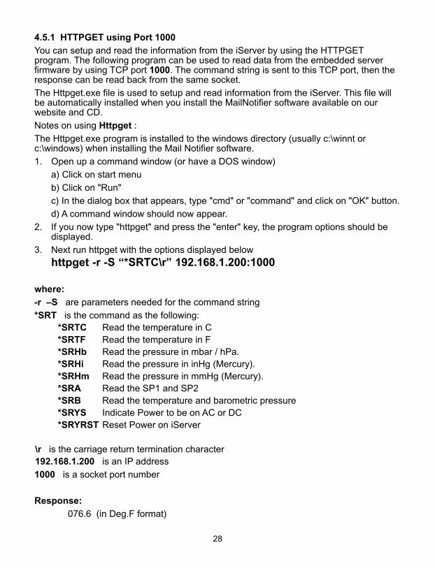
4.5.1 HTTPGET using Port 1000
You can setup and read the information from the iServer by using the HTTPGETprogram. The following program can be used to read data from the embedded serverfirmware by using TCP port 1000. The command string is sent to this TCP port, then theresponse can be read back from the same socket.
The Httpget.exe file is used to setup and read information from the iServer. This file willbe automatically installed when you install the MailNotifier software available on ourwebsite and CD.
Notes on using Httpget :
The Httpget.exe program is installed to the windows directory (usually c:\winnt orc:\windows) when installing the Mail Notifier software.
1. Open up a command window (or have a DOS window)
a) Click on start menu
b) Click on "Run"
c) In the dialog box that appears, type "cmd" or "command" and click on "OK" button.
d) A command window should now appear.
2. If you now type "httpget" and press the "enter" key, the program options should bedisplayed.
3. Next run httpget with the options displayed below
httpget -r -S “*SRTC\r” 192.168.1.200:1000
where:
-r –S are parameters needed for the command string
*SRT is the command as the following:*SRTC Read the temperature in C*SRTF Read the temperature in F*SRHb Read the pressure in mbar / hPa.*SRHi Read the pressure in inHg (Mercury).*SRHm Read the pressure in mmHg (Mercury).*SRA Read the SP1 and SP2*SRB Read the temperature and barometric pressure*SRYS Indicate Power to be on AC or DC*SRYRST Reset Power on iServer
\r is the carriage return termination character192.168.1.200 is an IP address
1000 is a socket port number
Response:
076.6 (in Deg.F format)
29
4.5.2 HTTPGET and ARP to setup Device IP Address
Use the iCONNECT software, which may be downloaded from our website, todo these IP changes whenever possible.
Use ARP first to assign the mac address to a static IP address in computer arp table bythis command:
apr –s 192.168.1.200 00-03-34-00-00-06-b6
Then use the following command to assign new IP to the device:
Httpget –r –S "00000000" 192.168.1.200:1
where:
“00000000” is admin. password. If the password is wrong, the unit will ignore the new IP.If the new IP is taken, you will get the message " New IP is Assigned" after the httpgetcommand. The device will reset automatically.
“192.168.1.200” is an example of an IP addresss. It is replaced with an IP addresssuitable for your network
“00-03-34-00-00-06-b6” is replaced with your iServer product MAC address.
30
4.6 ARP Protocol
ARP is the Internet layer protocol responsible for matching or obtaining the MAC(hardware) address that corresponds to a particular IP address. The ARP commandallows the user to view the current contents of the ARP cache of the local computer(residing on the same network). Microsoft includes the ARP.EXE utility for viewing andmodifying the ARP cache with its Windows products. The following ARP commands canbe used to view cache entries:• arp –a ➞ Use this command to view all ARP cache entries.• arp –a plus IP address ➞ Use this command to view ARP cache entries associated
with one particular interface on a network with multiple adapters.• arp –g ➞ Same as arp –a.• arp –N ➞ Use this command to display ARP entries for specific network interface.• arp – s plus IP address plus Physical address ➞ Use this command to manually add
a permanent static entry to the ARP cache.• arp –d ➞ Use this command to manually delete a static entry.
Ping the destination computer using IP address first before using the arp -acommand.
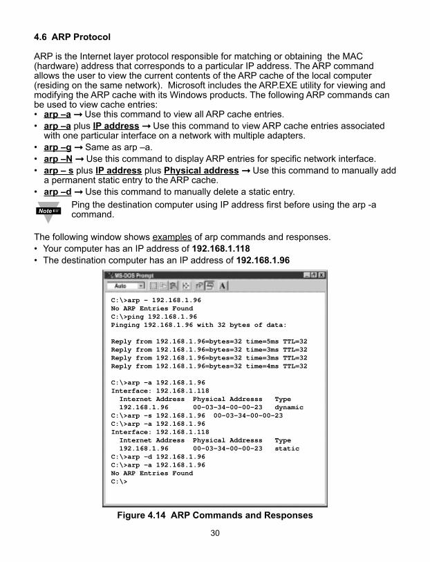
The following window shows examples of arp commands and responses.• Your computer has an IP address of 192.168.1.118• The destination computer has an IP address of 192.168.1.96
Figure 4.14 ARP Commands and Responses
C:\>arp - 192.168.1.96No ARP Entries FoundC:\>ping 192.168.1.96Pinging 192.168.1.96 with 32 bytes of data:
Reply from 192.168.1.96=bytes=32 time=5ms TTL=32Reply from 192.168.1.96=bytes=32 time=3ms TTL=32Reply from 192.168.1.96=bytes=32 time=3ms TTL=32Reply from 192.168.1.96=bytes=32 time=4ms TTL=32
C:\>arp -a 192.168.1.96Interface: 192.168.1.118 Internet Address Physical Addresss Type 192.168.1.96 00-03-34-00-00-23 dynamicC:\>arp -s 192.168.1.96 00-03-34-00-00-23C:\>arp -a 192.168.1.96Interface: 192.168.1.118 Internet Address Physical Addresss Type 192.168.1.96 00-03-34-00-00-23 staticC:\>arp -d 192.168.1.96C:\>arp -a 192.168.1.96No ARP Entries FoundC:\>
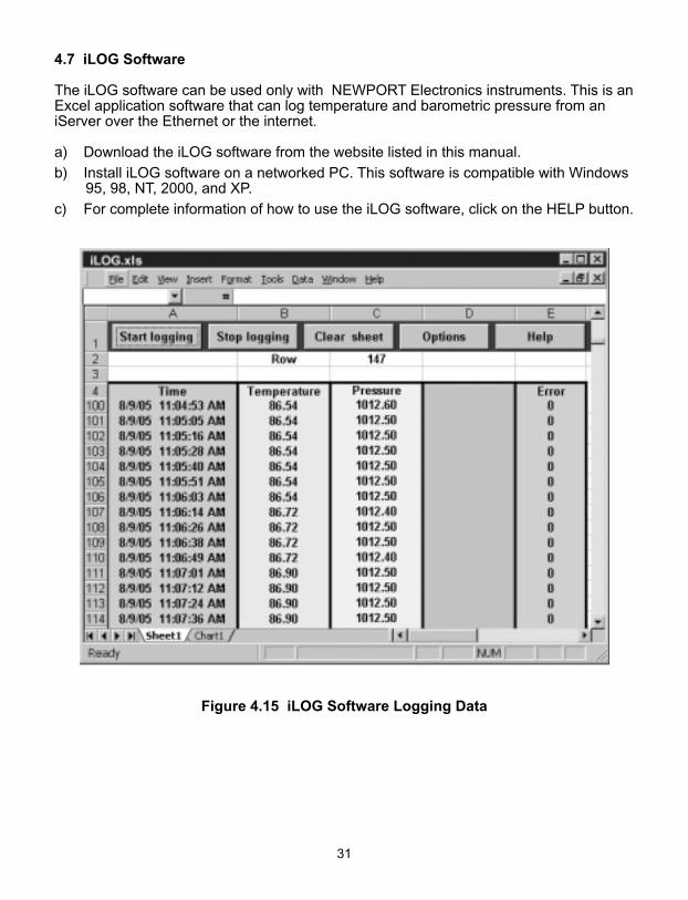
4.7 iLOG Software
The iLOG software can be used only with NEWPORT Electronics instruments. This is anExcel application software that can log temperature and barometric pressure from aniServer over the Ethernet or the internet.
a) Download the iLOG software from the website listed in this manual.
b) Install iLOG software on a networked PC. This software is compatible with Windows95, 98, NT, 2000, and XP.
c) For complete information of how to use the iLOG software, click on the HELP button.
Figure 4.15 iLOG Software Logging Data
31
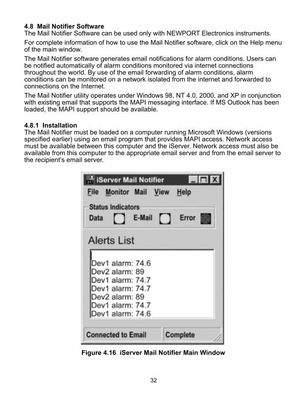
4.8 Mail Notifier SoftwareThe Mail Notifier Software can be used only with NEWPORT Electronics instruments.
For complete information of how to use the Mail Notifier software, click on the Help menuof the main window.
The Mail Notifier software generates email notifications for alarm conditions. Users canbe notified automatically of alarm conditions monitored via internet connectionsthroughout the world. By use of the email forwarding of alarm conditions, alarmconditions can be monitored on a network isolated from the internet and forwarded toconnections on the Internet.
The Mail Notifier utility operates under Windows 98, NT 4.0, 2000, and XP in conjunctionwith existing email that supports the MAPI messaging interface. If MS Outlook has beenloaded, the MAPI support should be available.
4.8.1 InstallationThe Mail Notifier must be loaded on a computer running Microsoft Windows (versionsspecified earlier) using an email program that provides MAPI access. Network accessmust be available between this computer and the iServer. Network access must also beavailable from this computer to the appropriate email server and from the email server tothe recipient’s email server.
Figure 4.16 iServer Mail Notifier Main Window
32
33
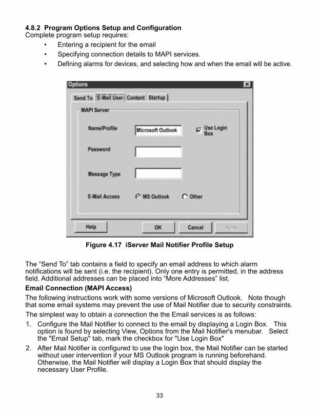
4.8.2 Program Options Setup and ConfigurationComplete program setup requires:
• Entering a recipient for the email
• Specifying connection details to MAPI services.
• Defining alarms for devices, and selecting how and when the email will be active.
Figure 4.17 iServer Mail Notifier Profile Setup
The “Send To” tab contains a field to specify an email address to which alarmnotifications will be sent (i.e. the recipient). Only one entry is permitted, in the addressfield. Additional addresses can be placed into “More Addresses” list.
Email Connection (MAPI Access)
The following instructions work with some versions of Microsoft Outlook. Note thoughthat some email systems may prevent the use of Mail Notifier due to security constraints.
The simplest way to obtain a connection the the Email services is as follows:
1. Configure the Mail Notifier to connect to the email by displaying a Login Box. Thisoption is found by selecting View, Options from the Mail Notifier's menubar. Selectthe "Email Setup" tab, mark the checkbox for "Use Login Box"
2. After Mail Notifier is configured to use the login box, the Mail Notifier can be startedwithout user intervention if your MS Outlook program is running beforehand.Otherwise, the Mail Notifier will display a Login Box that should display thenecessary User Profile.
34
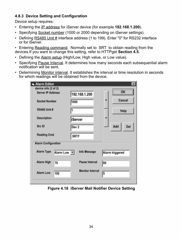
4.8.3 Device Setting and Configuration
Device setup requires:
• Entering the IP address for iServer device (for example 192.168.1.200).
• Specifying Socket number (1000 or 2000 depending on iServer settings).
• Defining RS485 Unit # interface address (1 to 199). Enter "0" for RS232 interface or for iServer.
• Entering Reading command. Normally set to SRT to obtain reading from thedevices.If you want to change this setting, refer to HTTPget Section 4.5.
• Defining the Alarm setup (High/Low, High value, or Low value).
• Specifying Pause Interval. It determines how many seconds each subsequential alarmnotification will be sent.
• Determining Monitor interval. It establishes the interval or time resolution in seconds for which readings will be obtained from the device.
Figure 4.18 iServer Mail Notifier Device Setting

35
PART 5 SPECIFICATIONS
SENSOR SPECIFICATIONSBAROMETRIC PRESSURE (B)Accuracy/Range: ±2.0 mbar / 0-1100 mbar (0-110 KPa)Resolution: 0.1 mbar
TEMPERATURE (T)Range*: 0°C to 70°C (32°F to 158°F)Accuracy*:± 0.8°C @ 20°C (± 1.5°F @ 68°F)± 2°C for -40 to 125°C (± 3.6°F for -40 to 257°F) *Note: extended temperature range is forIndustrial Probe only, the iServer’soperating temperature is 0 to 70°C.
Response Time: 5 seconds (63% slowly moving air)Repeatability: ±0.1°CResolution: 0.01°C, 14bit
PROBE PHYSICAL DIMENSIONSWand Probe: 159 mm lg x 19 mm dia (6.25” x 0.75")Cable with DB9 connector: 152 mm long (6")Cable operating temp: 0 to 80°C (32 to 176°F)Industrial Probe: 137mm lg x 16mm dia (5” x 0.63")Cable with DB9 or stripped leads:6.1m long (20’)Cable operating temp:0 to 105°C (32 to 221°F)
iSERVER SPECIFICATIONSINTERFACEEthernet: 10Base-T (RJ45) Sensor: Digital 4-wire (DB-9) Supported Protocols: TCP/IP, UDP/IP, ARP, ICMP, DHCP, DNS,HTTP, and TelnetLED Indicators: Network Activity,Network Link, and DiagnosticsLCD Display: 16 digits, 6mm (0.23”)
Processor: Enhanced 8051, 22 MHzMemory: 512 Kbytes Flash, 16 KbytesSRAMMemory Data Flash Card: 2 Mbytes or 2 months of data storage at 10 secondlogging intervals, or 1 year at 1 minutelogging intervals. Atmel# AT45DCB002Optional Flash Cards: 4 Mbyte (2 years at 1 minute intervals)8 Mbyte (4 years at 1 minute intervals)Relay Outputs: Two relays 1.5A @ 30VdcManagement: Device configuration andmonitoring through embedded WEBserverEmbedded WEB Server: Serves WEBpages containing real-time data and liveupdated charts within definable timeintervals.Agency Approvals: FCC-B, CE Software: Field firmware upgradeable.Including an Excel program for automaticdata logging within definable timeintervals, compatible with all Windowsoperating systems.POWERPower Input: 9-12 VdcConsumption: 2.5 W max. Safety Qualified ac Power Adapter Nominal Output: 9 Vdc @ 0.5 AInput: 100-240 Vac, 50/60HzBattery: 9 Vdc, alkaline approximately 650 mA hours
ENVIRONMENTALOperating Temperature:0 to 70°C (32 to 158°F)Storage Temperature: -40 to 125°C (-40 to 257°F)
PACKAGINGMaterial: Metal case with flange mountiServer Housing Dimensions:36.6H x 62W x 90Dmm (1.44 x 2.93 x 3.56 “)Weight: 298 g (0.8 lbs.)
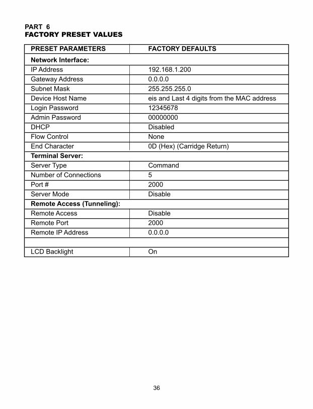
PART 6FACTORY PRESET VALUES
PRESET PARAMETERS FACTORY DEFAULTS
Network Interface:
IP Address 192.168.1.200
Gateway Address 0.0.0.0
Subnet Mask 255.255.255.0
Device Host Name eis and Last 4 digits from the MAC address
Login Password 12345678
Admin Password 00000000
DHCP Disabled
Flow Control None
End Character 0D (Hex) (Carridge Return)
Terminal Server:
Server Type Command
Number of Connections 5
Port # 2000
Server Mode Disable
Remote Access (Tunneling):
Remote Access Disable
Remote Port 2000
Remote IP Address 0.0.0.0
LCD Backlight On
36
APPENDIX A GLOSSARY
User of this manual should be familiar with following definitions:
ARP (Address Resolution Protocol) is a protocol for mapping an Internet Protocol address (IP address) to a physical machine address that is recognized in the localnetwork. For example, the IP address in use today is an address that is 32-bits long. In an Ethernet local area network, however, addresses for attached devices are 48-bitslong. (The physical machine address is also known as a Media Access Control or MACaddress.) A table, usually called the ARP cache, is used to maintain a correlation betweeneach MAC address and its corresponding IP address. ARP provides the protocol rules formaking this correlation and providing address conversion in both directions.
Ethernet is a network protocol defined by the IEEE 802.3 standard. Ethernet-based networks use MAC Address rather then IP Address to exchange data between computers.By using ARP and adding TCP/IP support, Ethernet devices may be connected as part ofthe Internet. An Ethernet LAN typically uses coaxial cable or special grades of twisted pairwires. The most commonly installed Ethernet systems are called 10BASE-T and providetransmission speeds up to 10 Mbps. Devices are connected to the cable and compete foraccess using a Carrier Sense Multiple Access with Collision Detection (CSMA/CD)protocol.
IP (Internet Protocol) is the method or protocol by which data is sent from one computerto another on the Internet.
IP address (Internet Protocol address) is a 32-bit number that identifies each sender orreceiver of information that is sent in packets across the Internet.
IP Netmask is a 32-bit pattern of bits used to determine which part of the IP address is thenetwork portion and which part is the host portion.
MAC (Media Access Control) Address is your computer's unique hardware number.When you're connected to the Internet from your computer, a correspondence table relatesyour IP address to your computer's physical (MAC) address on the LAN.
Ping is a utility that tests the network connectivity. It is used to determine if the host iscapable of exchanging information with another host.
Port number/Socket number is a way to identify a specific process to which an Internetor other network message is to be forwarded when it arrives at a server. It is a predefinedaddress that serves as a route from the application to the Transport layer or from theTransport layer to the application of the TCP/IP system.
Sockets are a method for communication between a client program and a server programin a network and defined as "the endpoint in a connection." Information transferred acrossthe Internet primarily occurs between sockets.
TCP/IP (Transmission Control Protocol/Internet Protocol) is the basic communicationlanguage or protocol of the Internet. When you are set up with direct access to theInternet, your computer is provided with a copy of the TCP/IP program just as every othercomputer that you may send messages to or get information from also has a copy ofTCP/IP. TCP/IP often is used as a general term to indicate generic access to the Internet.
UDP/IP (User Datagram Protocol/Internet Protocol) is the TCP/IP standard protocol thatallows an application program on one machine to send a datagram to an applicationprogram on another. The UDP can be either in Broadcast or Directed form. The BroadcastUDP transmits data to every node on the same network. The Directed UDP transmits datato one node only.
37
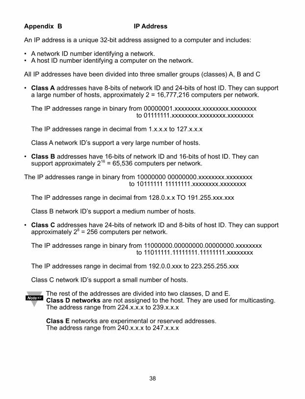
Appendix B IP Address
An IP address is a unique 32-bit address assigned to a computer and includes:
• A network ID number identifying a network.• A host ID number identifying a computer on the network.
All IP addresses have been divided into three smaller groups (classes) A, B and C
• Class A addresses have 8-bits of network ID and 24-bits of host ID. They can support a large number of hosts, approximately 2 = 16,777,216 computers per network.
The IP addresses range in binary from 00000001.xxxxxxxx.xxxxxxxx.xxxxxxxxto 01111111.xxxxxxxx.xxxxxxxx.xxxxxxxx
The IP addresses range in decimal from 1.x.x.x to 127.x.x.x
Class A network ID’s support a very large number of hosts.
• Class B addresses have 16-bits of network ID and 16-bits of host ID. They can support approximately 216 = 65,536 computers per network.
The IP addresses range in binary from 10000000 00000000.xxxxxxxx.xxxxxxxxto 10111111 11111111.xxxxxxxx.xxxxxxxx
The IP addresses range in decimal from 128.0.x.x TO 191.255.xxx.xxx
Class B network ID’s support a medium number of hosts.
• Class C addresses have 24-bits of network ID and 8-bits of host ID. They can support approximately 28 = 256 computers per network.
The IP addresses range in binary from 11000000.00000000.00000000.xxxxxxxx to 11011111.11111111.11111111.xxxxxxxx
The IP addresses range in decimal from 192.0.0.xxx to 223.255.255.xxx
Class C network ID’s support a small number of hosts.
The rest of the addresses are divided into two classes, D and E.Class D networks are not assigned to the host. They are used for multicasting. The address range from 224.x.x.x to 239.x.x.x
Class E networks are experimental or reserved addresses.The address range from 240.x.x.x to 247.x.x.x
38
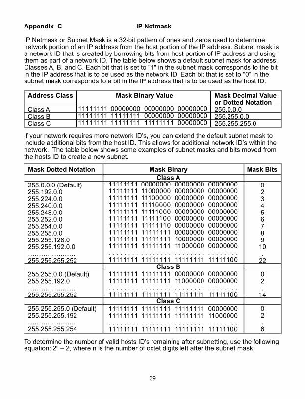
Appendix C IP Netmask
IP Netmask or Subnet Mask is a 32-bit pattern of ones and zeros used to determinenetwork portion of an IP address from the host portion of the IP address. Subnet mask isa network ID that is created by borrowing bits from host portion of IP address and usingthem as part of a network ID. The table below shows a default subnet mask for addressClasses A, B, and C. Each bit that is set to "1" in the subnet mask corresponds to the bitin the IP address that is to be used as the network ID. Each bit that is set to "0" in thesubnet mask corresponds to a bit in the IP address that is to be used as the host ID.
Address Class Mask Binary Value Mask Decimal Valueor Dotted Notation
Class A 255.0.0.0Class B 255.255.0.0Class C 255.255.255.0
If your network requires more network ID’s, you can extend the default subnet mask toinclude additional bits from the host ID. This allows for additional network ID’s within thenetwork. The table below shows some examples of subnet masks and bits moved fromthe hosts ID to create a new subnet.
Mask Dotted Notation Mask Binary Mask BitsClass A
255.0.0.0 (Default) 0255.192.0.0 2255.224.0.0 3255.240.0.0 4255.248.0.0 5255.252.0.0 6255.254.0.0 7255.255.0.0 8255.255.128.0 9255.255.192.0.0 10……………......... .255.255.255.252 22
Class B255.255.0.0 (Default) 0255.255.192.0 2……………......... .255.255.255.252 14
Class C255.255.255.0 (Default) 0255.255.255.192 2…………………. .255.255.255.254 6
To determine the number of valid hosts ID’s remaining after subnetting, use the followingequation: 2n – 2, where n is the number of octet digits left after the subnet mask.
39
111111111111111111111111
000000001111111111111111
000000000000000011111111
000000000000000000000000
11111111111111111111111111111111111111111111111111111111111111111111111111111111. . . . . . . .11111111
00000000110000001110000011110000111110001111110011111110111111111111111111111111. . . . . . . .11111111
00000000000000000000000000000000000000000000000000000000000000001000000011000000. . . . . . . .11111111
00000000000000000000000000000000000000000000000000000000000000000000000000000000. . . . . . . .11111100
1111111111111111. . . . . . . .11111111
1111111111111111. . . . . . . .11111111
0000000011000000. . . . . . . .11111111
0000000000000000. . . . . . . .11111100
1111111111111111. . . . . . . .11111111
1111111111111111. . . . . . . .11111111
1111111111111111. . . . . . . .11111111
0000000011000000. . . . . . . .11111100
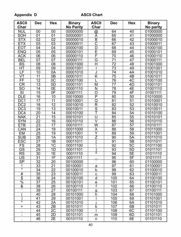
Appendix D ASCII Chart
ASCII Dec Hex Binary ASCII Dec Hex BinaryChar No Parity Char No parityNUL 00 00 00000000 @ 64 40 01000000SOH 01 01 00000001 A 65 41 01000000STX 02 02 00000010 B 66 42 01000010ETX 03 03 00000011 C 67 43 01000011EOT 04 04 00000100 D 68 44 01000100ENQ 05 05 00000101 E 69 45 01000101ACK 06 06 00000110 F 70 46 01000110BEL 07 07 00000111 G 71 47 01000111BS 08 08 00001000 H 72 48 01001000HT 09 09 00001001 I 73 49 01001001LF 10 0A 00001010 J 74 4A 01001010VT 11 0B 00001011 K 75 4B 01001011FF 12 0C 00001100 L 76 4C 01001100CR 13 0D 00001101 M 77 4D 01001101SO 14 0E 00001110 N 78 4E 01001110SI 15 0F 00001111 O 79 4F 01001111
DLE 16 10 00010000 P 80 50 01010000DC1 17 11 00010001 Q 81 51 01010001DC2 18 12 00010010 R 82 52 01010010DC3 19 13 00010011 S 83 53 01010011DC4 20 14 00010100 T 84 54 01010100NAK 21 15 00010101 U 85 55 01010101SYN 22 16 00010110 V 86 56 01010110ETB 23 17 00010111 W 87 57 01010111CAN 24 18 00011000 X 88 58 01011000EM 25 19 00011001 Y 89 59 01011001
SUB 26 1A 00011010 Z 90 5A 01011010ESC 27 1B 00011011 [ 91 5B 01011011FS 28 1C 00011100 \ 92 5C 01011100GS 29 1D 00011101 ] 93 5D 01011101RS 30 1E 00011110 ^ 94 5E 01011110US 31 1F 00011111 _ 95 5F 01011111SP 32 20 00100000 ` 96 60 01100000! 33 21 00100001 a 97 61 01100001" 34 22 00100010 b 98 62 01100010# 35 23 00100011 c 99 63 01100011$ 36 24 00100100 d 100 64 01100100% 37 25 00100101 e 101 65 01100101& 38 26 00100110 f 102 66 01100110‘ 39 27 00100111 g 103 67 01100111( 40 28 00101000 h 104 68 01101000) 41 29 00101001 I 105 69 01101001* 42 2A 00101010 j 106 6A 01101010+ 43 2B 00101011 k 107 6B 01101011, 44 2C 00101100 l 108 6C 01101100- 45 2D 00101101 m 109 6D 01101101. 46 2E 00101110 n 110 6E 01101110
40

Appendix D ASCII Chart Continuation/ 47 2F 00101111 o 111 6F 011011110 48 30 00110000 p 112 70 011100001 49 31 00110001 q 113 71 011100012 50 32 00110010 r 114 72 011100103 51 33 00110011 s 115 73 011100114 52 34 00110100 t 116 74 011101005 53 35 00110101 u 117 75 011101016 54 36 00110110 v 118 76 011101107 55 37 00110111 w 119 77 011101118 56 38 00111000 x 120 78 011110009 57 39 00111001 y 121 79 01111001: 58 3A 00111010 z 122 7A 01111010; 59 3B 00111011 { 123 7B 01111011< 60 3C 00111100 | 124 7C 01111100= 61 3D 00111101 } 125 7D 01111101> 62 3E 00111110 ~ 126 7E 01111110? 63 3F 00111111 DEL 127 7F 01111111
ASCII Control CodesASCII Dec Hex Ctrl Key Definition ASCII Dec Hex Ctrl Key DefinitionChar Equiv. Char Equiv.NUL 00 00 Crtl @ Null Character DC1 17 11 Crtl Q Data Control 1
- XONSOH 01 01 Crtl A Start of DC2 18 12 Crtl R Data Control 2
HeaderSTX 02 02 Crtl B Start of Text DC3 19 13 Crtl S Data Control 3
- XOFFETX 03 03 Crtl C End of Text DC4 20 14 Crtl T Data Control 4EOT 04 04 Crtl D End of NAK 21 15 Crtl U Negative
Transmission AcknowledgeENQ 05 05 Crtl E Inquiry SYN 22 16 Crtl V Synchronous
IdleACK 06 06 Crtl F Acknowledge ETB 23 17 Crtl W End of Trans
BlockBEL 07 07 Crtl G Bell CAN 24 18 Crtl X CancelBS 08 08 Crtl H Back Space EM 25 19 Crtl Y End of MediumHT 09 09 Crtl I Horizontal SUB 26 1A Crtl Z Substitute
TabulationLF 10 0A Crtl J Line Feed ESC 27 1B Crtl [ EscapeVT 11 0B Crtl K Vertical FS 28 1C Crtl \ File Separator
TabulationFF 12 0C Crtl L Form Feed GS 29 1D Crtl ] Group
SeparatorCR 13 0D Crtl M Carriage RS 30 1E Crtl | Record
Return SeparatorSO 14 0E Crtl N Shift Out US 31 1F Crtl _ Unit SeparatorSI 15 0F Crtl O Shift In SP 32 20 Space
DLE 16 10 Crtl P Data LinkEscape
41

42
PART 7APPROVALS INFORMATION7.1 CE APPROVAL
This product conforms to the EMC directive 89/336/EEC amended by 93/68/EEC,and with the European Low Voltage Directive 72/23/EEC.
Electrical Safety EN61010-1:2001Safety requirements for electrical equipment for measurement, control and laboratory.Basic InsulationPollution Degree 2Dielectric withstand Test per 1 min
• Input Power to Sensor Metal Body: none• Input Power to Ethernet Output: 1500Vac• Input Power to Relays: 1500Vac• Ethernet Output to Relays: 1500Vac
Measurement Category ICategory I are measurements performed on circuits not directly connected to the MainsSupply (power). Unit measures Air Temperature and Barometric Pressure.Transients Overvoltage Surge (1.2/50uS Pulse)
• Input Power: 500V Transients Overvoltage• Ethernet: 1500V Transients Overvoltage
Note: The ac/dc power adaptor must have Safety Qualified Agency Approvals for CE with Double Insulation rating. The ac/dc power adaptor is 9Vdc.The minimum output current rating is 500mA.
EMC EN61000-6-1:2001 (Immunity) and EN61000-6-3:2001 (Emmissions)Immunity requirements for residential, commercial and light-industrial environments
• EMC Emissions Table 1, Class B • EMC Immunity Table 1: Enclosure
Table 2: Signal Lines PortsTable 3: Dc input/Dc output Ports
EMC EN61326:1997 + and A1:1998 + A2:2001Immunity and Emissions requirements for electrical equipment for measurement, controland laboratory.
• EMC Emissions Table 4, Class B of EN61326• EMC Immunity Table 1 of EN61326
Note: I/O lines / sensor cables require shielded cables and these cables must be locatedon conductive cable trays or in conduits.
Refer to the EMC and Safety installation considerations (Guidelines) of this manual foradditional information.
7.2 FCCThis device complies with Part 15, Subpart B, Class B of the FCC rules.

WARRANTY/DISCLAIMEROMEGA ENGINEERING, INC. warrants this unit to be free of defects in materials and workmanship for a period of one (1) yearfrom the date of purchase. In addition to OMEGA’s standard warranty period, OMEGA Engineering will extend the warrantyperiod for one (1) additional year if the warranty card enclosed with each instrument is returned to OMEGA.
If the unit malfunctions, it must be returned to the factory for evaluation. OMEGA’s Customer Service Department will issue anAuthorized Return (AR) number immediately upon phone or written request. Upon examination by OMEGA, if the unit is foundto be defective, it will be repaired or replaced at no charge. OMEGA’s WARRANTY does not apply to defects resulting from anyaction of the purchaser, including but not limited to mishandling, improper interfacing, operation outside of design limits,improper repair, or unauthorized modification. This WARRANTY is VOID if the unit shows evidence of having been tamperedwith or shows evidence of having been damaged as a result of excessive corrosion; or current, heat, moisture or vibration;improper specification; misapplication; misuse or other operating conditions outside of OMEGA’s control. Components whichwear are not warranted, including but not limited to contact points, fuses, and triacs.
OMEGA is pleased to offer suggestions on the use of its various products. However, OMEGA neither assumesresponsibility for any omissions or errors nor assumes liability for any damages that result from the use of itsproducts in accordance with information provided by OMEGA, either verbal or written. OMEGA warrants only that theparts manufactured by it will be as specified and free of defects. OMEGA MAKES NO OTHER WARRANTIES ORREPRESENTATIONS OF ANY KIND WHATSOEVER, EXPRESS OR IMPLIED, EXCEPT THAT OF TITLE, AND ALLIMPLIED WARRANTIES INCLUDING ANY WARRANTY OF MERCHANTABILITY AND FITNESS FOR A PARTICULARPURPOSE ARE HEREBY DISCLAIMED. LIMITATION OF LIABILITY: The remedies of purchaser set forth herein areexclusive, and the total liability of OMEGA with respect to this order, whether based on contract, warranty, negligence,indemnification, strict liability or otherwise, shall not exceed the purchase price of the component upon which liabilityis based. In no event shall OMEGA be liable for consequential, incidental or special damages.
CONDITIONS: Equipment sold by OMEGA is not intended to be used, nor shall it be used: (1) as a “Basic Component”under 10 CFR 21 (NRC), used in or with any nuclear installation or activity; or (2) in medical applications or used onhumans. Should any Product(s) be used in or with any nuclear installation or activity, medical application, used onhumans, or misused in any way, OMEGA assumes no responsibility as set forth in our basic WARRANTY/DISCLAIMERlanguage, and, additionally, purchaser will indemnify OMEGA and hold OMEGA harmless from any liability or damagewhatsoever arising out of the use of the Product(s) in such a manner.
RETURN REQUESTS/INQUIRIESDirect all warranty and repair requests/inquiries to the OMEGA Customer Service Department. BEFORE RETURNINGANY PRODUCT(S) TO OMEGA, PURCHASER MUST OBTAIN AN AUTHORIZED RETURN (AR) NUMBER FROMOMEGA’S CUSTOMER SERVICE DEPARTMENT (IN ORDER TO AVOID PROCESSING DELAYS). The assigned ARnumber should then be marked on the outside of the return package and on any correspondence.
The purchaser is responsible for shipping charges, freight, insurance and proper packaging to prevent breakage intransit.
FOR WARRANTY RETURNS, please have the followinginformation available BEFORE contacting OMEGA:
1. Purchase Order number under which the product wasPURCHASED,
2. Model and serial number of the product under warranty,and
3. Repair instructions and/or specific problems relative tothe product.
FOR NON-WARRANTY REPAIRS, consult OMEGA for currentrepair charges. Have the following information availableBEFORE contacting OMEGA:
1. Purchase Order number to cover the COST of the repair,
2. Model and serial number of product, and
3. Repair instructions and/or specific problems relative to theproduct.
OMEGA’s policy is to make running changes, not model changes, whenever an improvement is possible. This affords ourcustomers the latest in technology and engineering.
© Copyright 2006 OMEGA ENGINEERING, INC. All rights reserved. This document may not be copied, photocopied,reproduced, translated, or reduced to any electronic medium or machine-readable form, in whole or in part, without the priorwritten consent of OMEGA ENGINEERING, INC.
TRADEMARK NOTICE: ®, omega.com®, , and ® are Trademarks of OMEGA ENGINEERING, INC.
PATENT NOTICE: This product is covered by one or more of the following patents: U.S. Pat. No. Des. 336,895; 5,274,577/CANADA 2052599; 2052600 / ITALY 1249456; 1250938 / FRANCE BREVET No. 91 12756 / SPAIN 2039150; 2048066 / UKPATENT No. GB2 249 837; GB2 248 954 / GERMANY DE 41 34398 C2. Other US and International Patents pending or applied for.
®

M4223/0806
Where Do I Find Everything I Need for Process Measurement and Control?
OMEGA…Of Course!Shop on line at omega.com
TEMPERATURE�� Thermocouple, RTD & Thermistor Probes, Connectors, Panels & Assemblies�� Wire: Thermocouple, RTD & Thermistor�� Calibrators & Ice Point References�� Recorders, Controllers & Process Monitors�� Infrared Pyrometers
PRESSURE, STRAIN AND FORCE�� Transducers & Strain Gauges�� Load Cells & Pressure Gauges�� Displacement Transducers�� Instrumentation & Accessories
FLOW/LEVEL�� Rotameters, Gas Mass Flowmeters & Flow Computers�� Air Velocity Indicators�� Turbine/Paddlewheel Systems�� Totalizers & Batch Controllers
pH/CONDUCTIVITY�� pH Electrodes, Testers & Accessories�� Benchtop/Laboratory Meters�� Controllers, Calibrators, Simulators & Pumps�� Industrial pH & Conductivity Equipment
DATA ACQUISITION�� Data Acquisition & Engineering Software�� Communications-Based Acquisition Systems�� Plug-in Cards for Apple, IBM & Compatibles�� Datalogging Systems�� Recorders, Printers & Plotters
HEATERS�� Heating Cable�� Cartridge & Strip Heaters�� Immersion & Band Heaters�� Flexible Heaters�� Laboratory Heaters
ENVIRONMENTALMONITORING AND CONTROL�� Metering & Control Instrumentation�� Refractometers�� Pumps & Tubing�� Air, Soil & Water Monitors�� Industrial Water & Wastewater Treatment�� pH, Conductivity & Dissolved Oxygen Instruments