Embed Size (px)
Citation preview
Applies to: MDS manual 05-2806A01
MDS iNET 900 Transceiver
MANUAL SUPPLEMENT
March 2004
Microwave Data Systems Inc., 175 Science Parkway, Rochester, NY 14620 USATel: +1 (585) 242-9600, FAX: +1 (585) 242-9620, Web: www.microwavedata.com
This supplement contains additions to the MDS iNET 900™ User’s Guide (MDS Part No. 05-2806A01). You should include a reference in your User’s Guide to this supplement.
Purpose of this Supplement
This supplement covers the MDS iNET 900 ENI, which provides expanded gateway and protocol conversion capabilities not found in the MDS iNET 900. Throughout this document, the iNET 900 ENI is referred to as iNET/ENI.
The iNET/ENI currently contains gateway conversion services for:
• TCP, UDP, and PPP: Identical to the iNET 900.
• DF1 to EIP: Provides EtherNet/IP (Ethernet Industrial Protocol) connectivity for DF1 full-duplex devices.
• MODBUS to MODBUS TCP: Provides Modbus TCP connectivity for Modbus RTU or Mod-bus ASCII Slave devices.
Additional gateway services and protocol support are planned for future firmware releases.
NOTE: This supplement assumes you have an understanding of Ethernet networking and TCP/IP.
1. SELECTING NEW PROTOCOLS
1 1SELECTING NEW IPPROTOCOLSPerform the following procedure to select one of the new protocols sup-ported by the iNET/ENI:
1. Access the MDS iNET’s Serial Configuration Wizard as described in Section 3.5 of the iNET 900 User’s Guide (05-2806A01).
2. Select the IP Protocol screen displays. See Figure 1-1 below.
MDS 05-4131A01, Rev. A MDS iNET 900 ENI Supplement 1
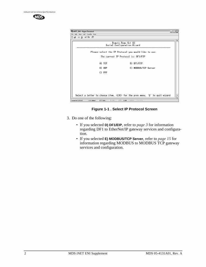
Figure 1-1 . Select IP Protocol Screen
3. Do one of the following:
• If you selected D) DF1/EIP, refer to page 3 for information regarding DF1 to EtherNet/IP gateway services and configura-tion.
• If you selected E) MODBUS/TCP Server, refer to page 15 for information regarding MODBUS to MODBUS TCP gateway services and configuration.
2 MDS iNET ENI Supplement MDS 05-4131A01, Rev. A
2. DF1 to EIP GATEWAYPROTOCOL
2.1 Introduction2The MDS iNET/ENI embeds the EtherNet/IP networking functionality of Rockwell’s ENI adaptor into the iNET 900 transceiver. With some minor exceptions, the iNET/ENI duplicates the functionality of the 1761-NET-ENI, providing EtherNET/IP connectivity to any device using the full-duplex DF1 protocol (Section 2.1.3 describes the differ-ences between the iNET/ENI and the 1761-NET-ENI).
2.1.1 Why Use the iNET/ENI?With the iNET/ENI, a separate EtherNet/IP adaptor is not needed when wireless EtherNet/IP networking is required for RS-232, full-duplex devices that use DF1 protocol, such as:
• MicroLogix™• ControLogix 1000 and 1500• SLC 5/03, 5/05• Other compatible DF1devices and third-party products
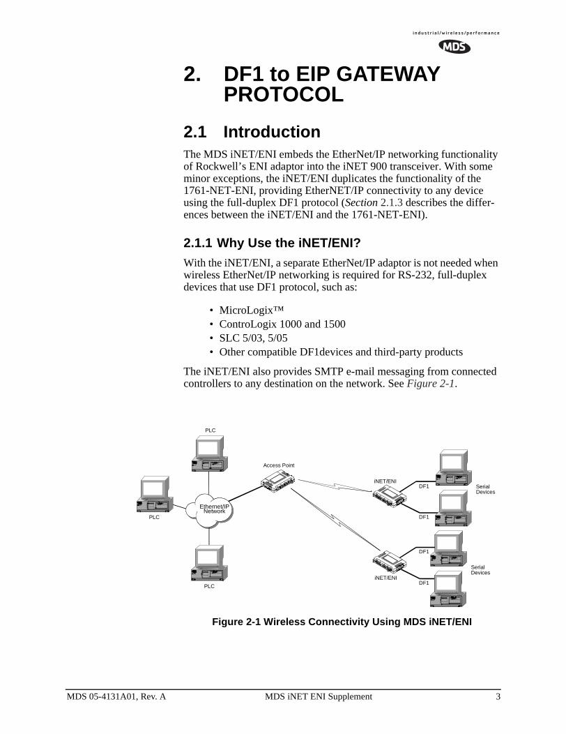
The iNET/ENI also provides SMTP e-mail messaging from connected controllers to any destination on the network. See Figure 2-1.
Figure 2-1 Wireless Connectivity Using MDS iNET/ENI
Access Point
PLC
iNET/ENI
iNET/ENI
SerialDevices
PLC
PLC
SerialDevices
DF1
DF1
DF1
DF1
Ethernet/IPNetwork
MDS 05-4131A01, Rev. A MDS iNET ENI Supplement 3
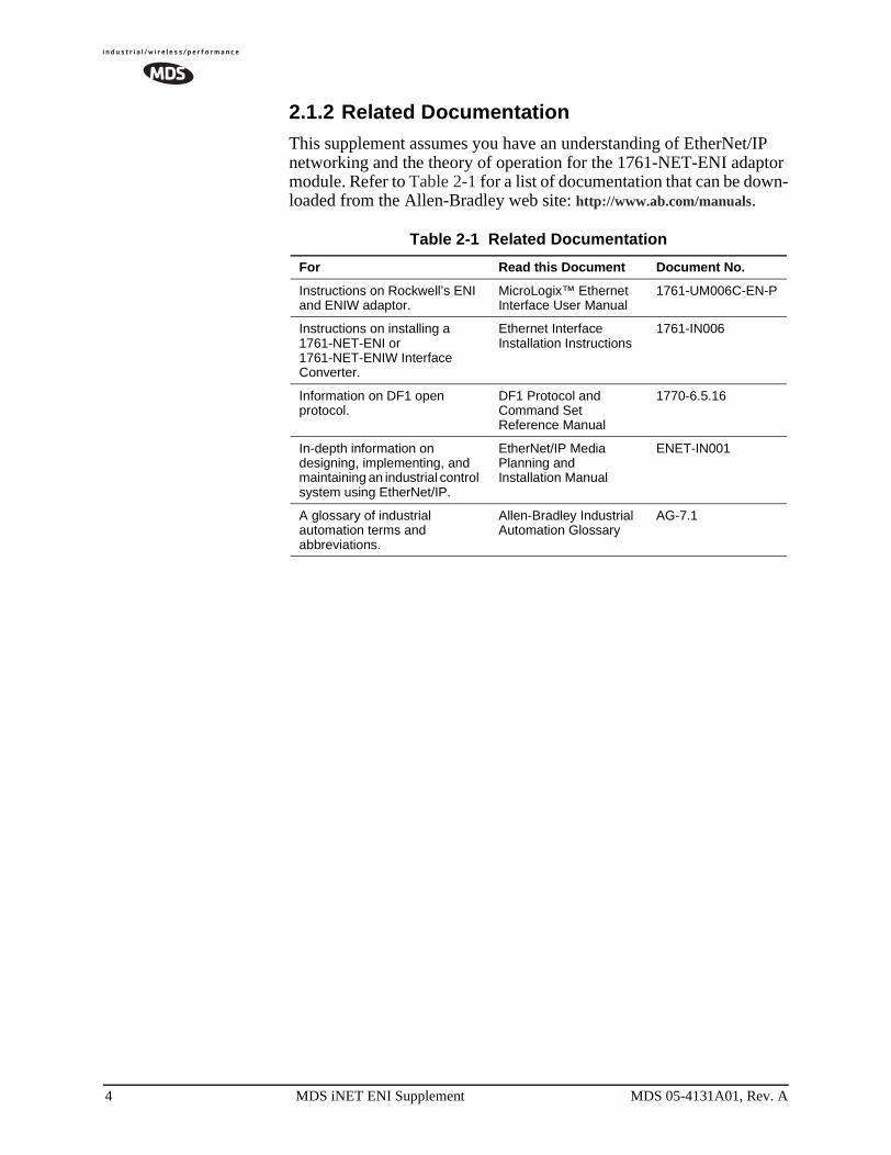
2.1.2 Related DocumentationThis supplement assumes you have an understanding of EtherNet/IP networking and the theory of operation for the 1761-NET-ENI adaptor module. Refer to Table 2-1 for a list of documentation that can be down-loaded from the Allen-Bradley web site: http://www.ab.com/manuals.
Table 2-1 Related Documentation
For Read this Document Document No.
Instructions on Rockwell’s ENI and ENIW adaptor.
MicroLogix™ Ethernet Interface User Manual
1761-UM006C-EN-P
Instructions on installing a 1761-NET-ENI or 1761-NET-ENIW Interface Converter.
Ethernet Interface Installation Instructions
1761-IN006
Information on DF1 open protocol.
DF1 Protocol and Command Set Reference Manual
1770-6.5.16
In-depth information on designing, implementing, and maintaining an industrial control system using EtherNet/IP.
EtherNet/IP Media Planning and Installation Manual
ENET-IN001
A glossary of industrial automation terms and abbreviations.
Allen-Bradley Industrial Automation Glossary
AG-7.1
4 MDS iNET ENI Supplement MDS 05-4131A01, Rev. A
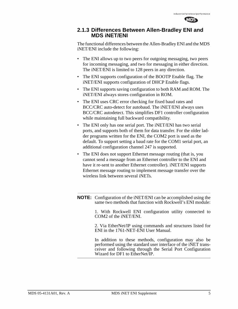
2.1.3 Differences Between Allen-Bradley ENI and MDS iNET/ENI
The functional differences between the Allen-Bradley ENI and the MDS iNET/ENI include the following:
• The ENI allows up to two peers for outgoing messaging, two peers for incoming messaging, and two for messaging in either direction. The iNET/ENI is limited to 128 peers in any direction.
• The ENI supports configuration of the BOOTP Enable flag. The iNET/ENI supports configuration of DHCP Enable flags.
• The ENI supports saving configuration to both RAM and ROM. The iNET/ENI always stores configuration in ROM.
• The ENI uses CRC error checking for fixed baud rates and BCC/CRC auto-detect for autobaud. The iNET/ENI always uses BCC/CRC autodetect. This simplifies DF1 controller configuration while maintaining full backward compatibility.
• The ENI only has one serial port. The iNET/ENI has two serial ports, and supports both of them for data transfer. For the older lad-der programs written for the ENI, the COM2 port is used as the default. To support setting a baud rate for the COM1 serial port, an additional configuration channel 247 is supported.
• The ENI does not support Ethernet message routing (that is, you cannot send a message from an Ethernet controller to the ENI and have it re-sent to another Ethernet controller). iNET/ENI supports Ethernet message routing to implement message transfer over the wireless link between several iNETs.
NOTE: Configuration of the iNET/ENI can be accomplished using thesame two methods that function with Rockwell’s ENI module:
1. With Rockwell ENI configuration utility connected toCOM2 of the iNET/ENI.
2. Via EtherNet/IP using commands and structures listed forENI in the 1761-NET-ENI User Manual.
In addition to these methods, configuration may also beperformed using the standard user interface of the iNET trans-ceiver and following through the Serial Port ConfigurationWizard for DF1 to EtherNet/IP.
MDS 05-4131A01, Rev. A MDS iNET ENI Supplement 5
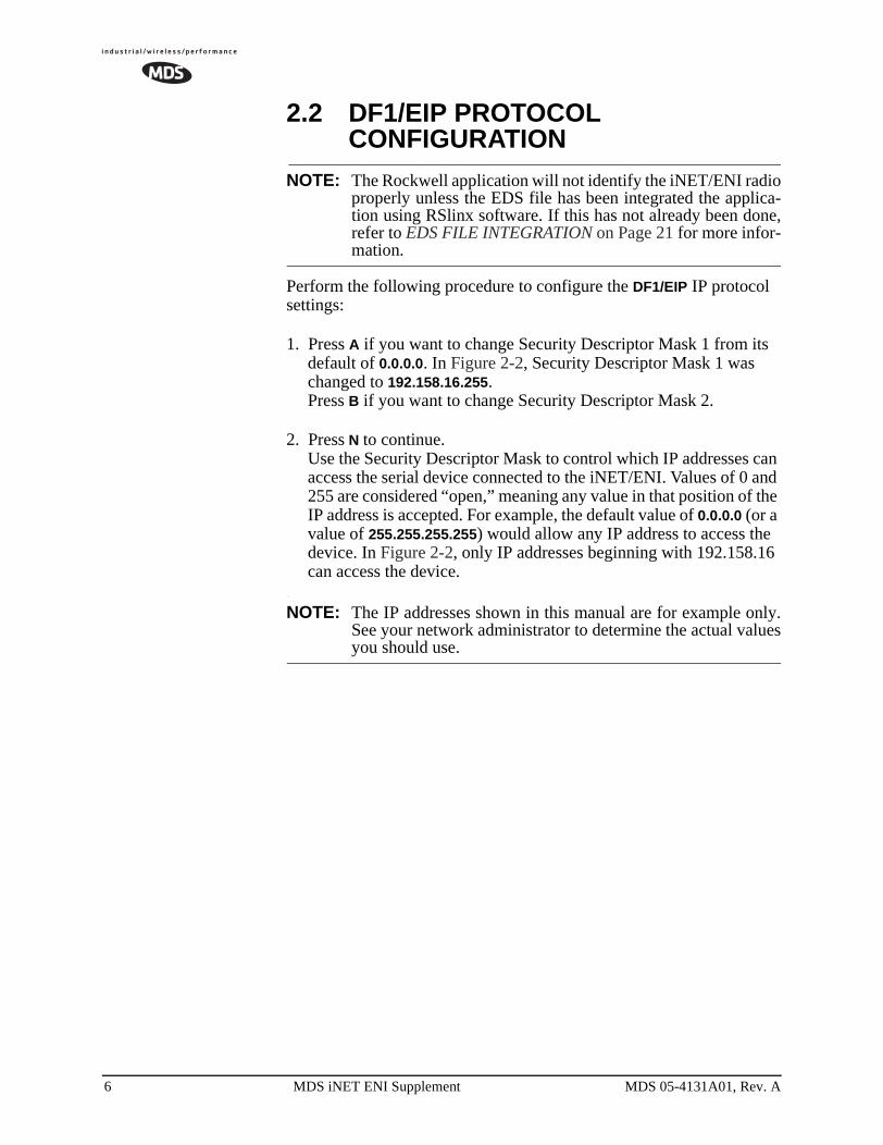
2.2 DF1/EIP PROTOCOL CONFIGURATION
NOTE: The Rockwell application will not identify the iNET/ENI radioproperly unless the EDS file has been integrated the applica-tion using RSlinx software. If this has not already been done,refer to EDS FILE INTEGRATION on Page 21 for more infor-mation.
Perform the following procedure to configure the DF1/EIP IP protocol settings:
1. Press A if you want to change Security Descriptor Mask 1 from its default of 0.0.0.0. In Figure 2-2, Security Descriptor Mask 1 was changed to 192.158.16.255.Press B if you want to change Security Descriptor Mask 2.
2. Press N to continue.Use the Security Descriptor Mask to control which IP addresses can access the serial device connected to the iNET/ENI. Values of 0 and 255 are considered “open,” meaning any value in that position of the IP address is accepted. For example, the default value of 0.0.0.0 (or a value of 255.255.255.255) would allow any IP address to access the device. In Figure 2-2, only IP addresses beginning with 192.158.16 can access the device.
NOTE: The IP addresses shown in this manual are for example only.See your network administrator to determine the actual valuesyou should use.
6 MDS iNET ENI Supplement MDS 05-4131A01, Rev. A
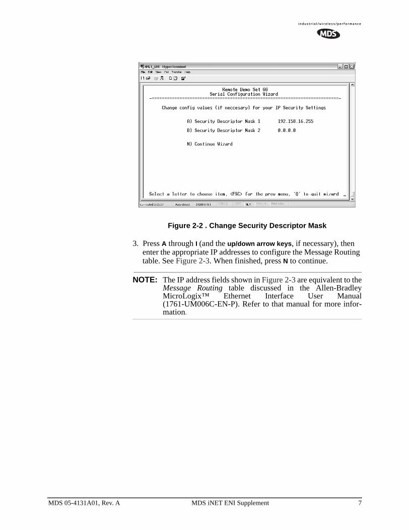
Figure 2-2 . Change Security Descriptor Mask
3. Press A through I (and the up/down arrow keys, if necessary), then enter the appropriate IP addresses to configure the Message Routing table. See Figure 2-3. When finished, press N to continue.
NOTE: The IP address fields shown in Figure 2-3 are equivalent to theMessage Routing table discussed in the Allen-BradleyMicroLogix™ Ethernet Interface User Manual(1761-UM006C-EN-P). Refer to that manual for more infor-mation.
MDS 05-4131A01, Rev. A MDS iNET ENI Supplement 7

Figure 2-3 . Enter Destination IP Addresses
8 MDS iNET ENI Supplement MDS 05-4131A01, Rev. A
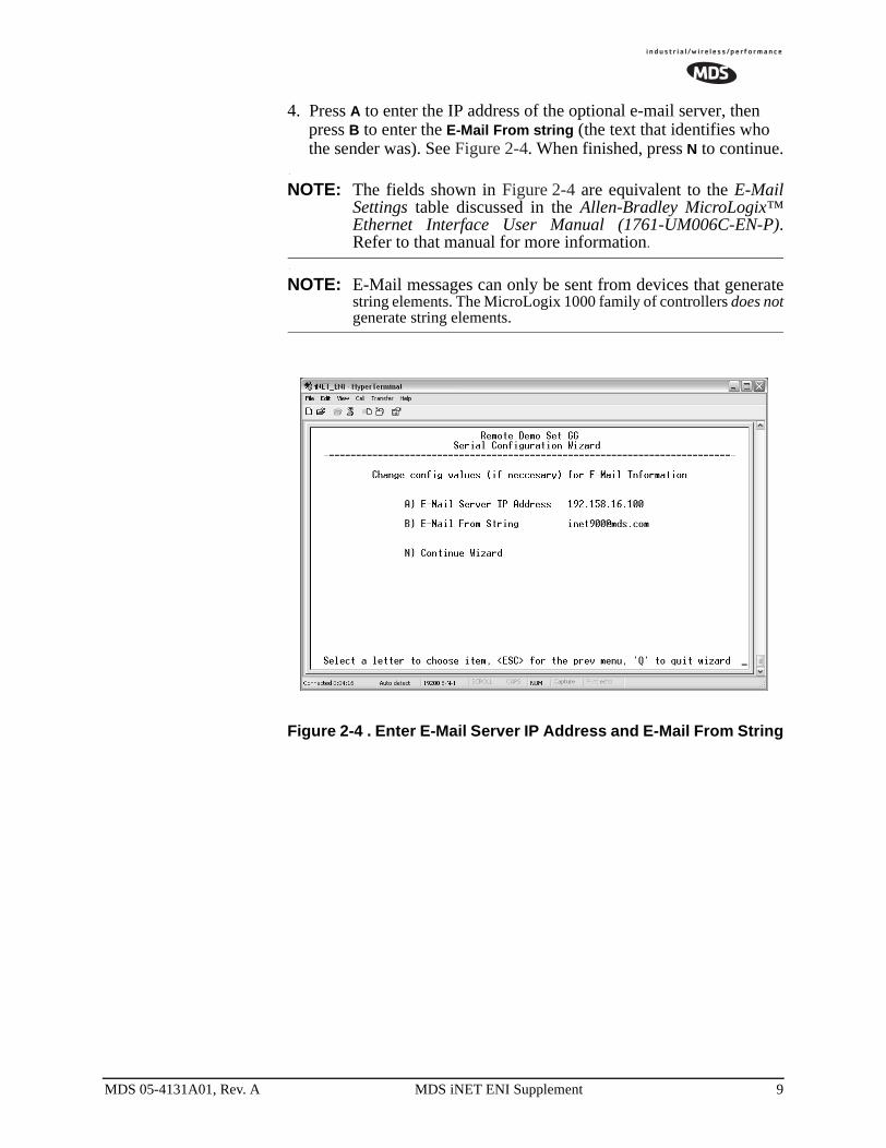
4. Press A to enter the IP address of the optional e-mail server, then press B to enter the E-Mail From string (the text that identifies who the sender was). See Figure 2-4. When finished, press N to continue.
NOTE: The fields shown in Figure 2-4 are equivalent to the E-MailSettings table discussed in the Allen-Bradley MicroLogix™Ethernet Interface User Manual (1761-UM006C-EN-P).Refer to that manual for more information.
NOTE: E-Mail messages can only be sent from devices that generatestring elements. The MicroLogix 1000 family of controllers does notgenerate string elements.
Figure 2-4 . Enter E-Mail Server IP Address and E-Mail From String
MDS 05-4131A01, Rev. A MDS iNET ENI Supplement 9
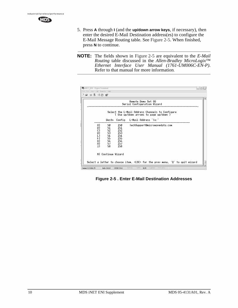
5. Press A through I (and the up/down arrow keys, if necessary), then enter the desired E-Mail Destination address(es) to configure the E-Mail Message Routing table. See Figure 2-5. When finished, press N to continue.
NOTE: The fields shown in Figure 2-5 are equivalent to the E-MailRouting table discussed in the Allen-Bradley MicroLogix™Ethernet Interface User Manual (1761-UM006C-EN-P).Refer to that manual for more information.
Figure 2-5 . Enter E-Mail Destination Addresses
10 MDS iNET ENI Supplement MDS 05-4131A01, Rev. A
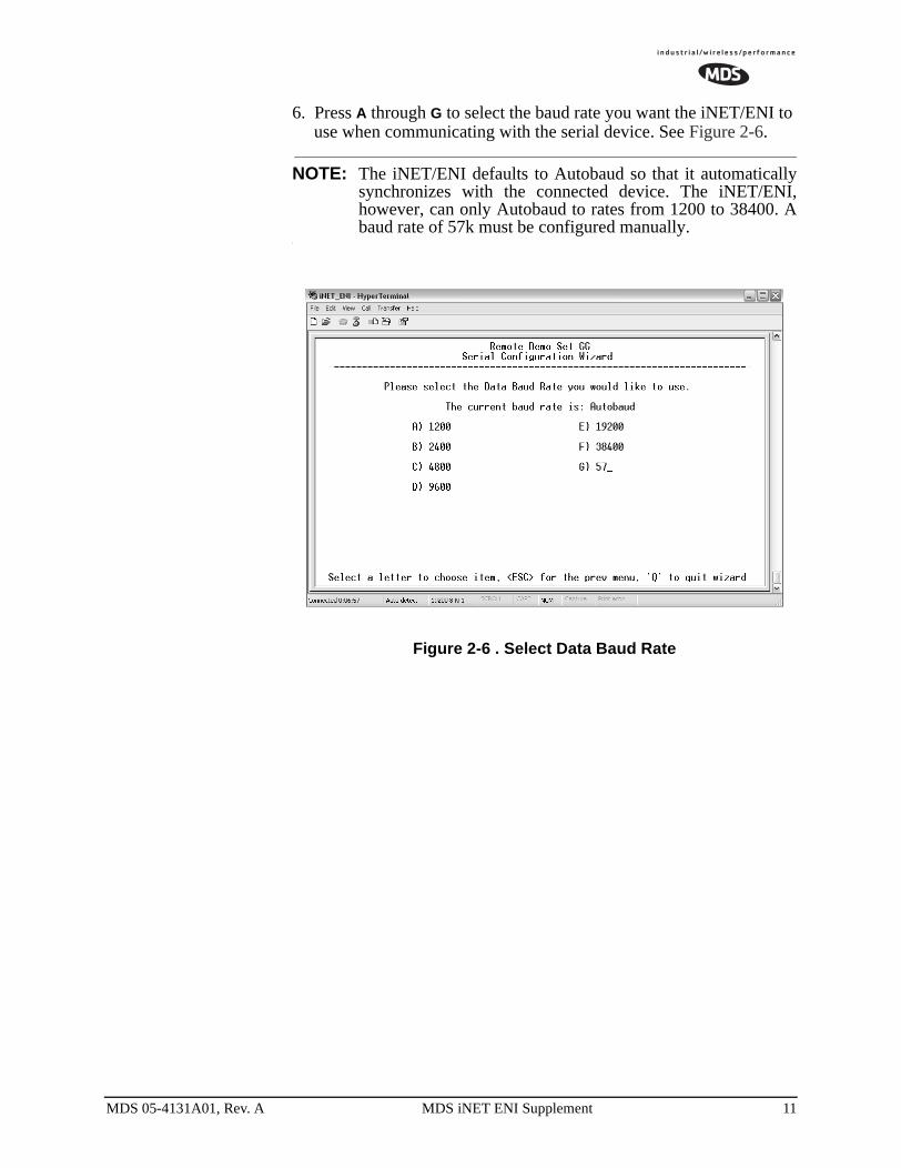
6. Press A through G to select the baud rate you want the iNET/ENI to use when communicating with the serial device. See Figure 2-6.
NOTE: The iNET/ENI defaults to Autobaud so that it automaticallysynchronizes with the connected device. The iNET/ENI,however, can only Autobaud to rates from 1200 to 38400. Abaud rate of 57k must be configured manually.
Figure 2-6 . Select Data Baud Rate
MDS 05-4131A01, Rev. A MDS iNET ENI Supplement 11
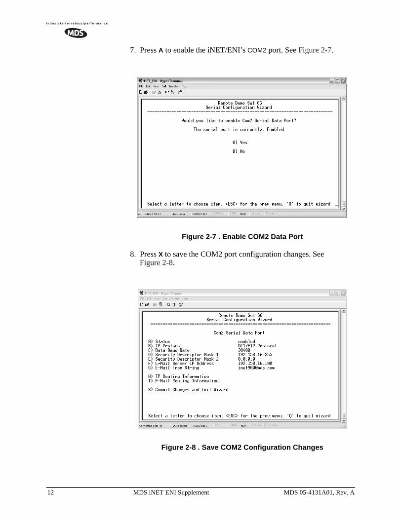
7. Press A to enable the iNET/ENI’s COM2 port. See Figure 2-7.
Figure 2-7 . Enable COM2 Data Port
8. Press X to save the COM2 port configuration changes. See Figure 2-8.
Figure 2-8 . Save COM2 Configuration Changes
12 MDS iNET ENI Supplement MDS 05-4131A01, Rev. A
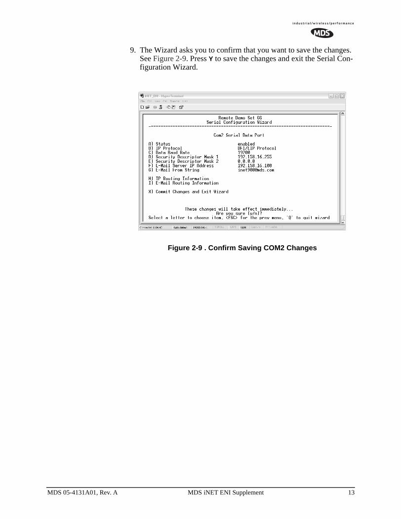
9. The Wizard asks you to confirm that you want to save the changes. See Figure 2-9. Press Y to save the changes and exit the Serial Con-figuration Wizard.
Figure 2-9 . Confirm Saving COM2 Changes
MDS 05-4131A01, Rev. A MDS iNET ENI Supplement 13

2.3 iNET/ENI Error CodesRefer to Table 2-2 for error codes generated by the iNET/ENI.
Table 2-2 iNET/ENI Error Codes
Error Code Description of Error Condition
10H Target node cannot respond because of incorrect command parameters or unsupported command. Possible causes:• The message’s data size is not valid• The data format is incorrect for any of the supported
PCCC messages• Register parameters are not formatted correctly, or
there is not enough data provided• RS-232 configuration packet data is not the correct
size• The Node Address is invalid or out-of-range• The distant ENI/ENIW, controller, or device may not
be responding• There may be a break in the connection between
the ENI devices or controllers• BOOTP/DF1 parameter is not valid
30H Target node responded with Remote station host is not there, disconnected, or shutdown.
D0H Caused by one of the following:• No IP address configured for the network or ENI not
configured for Node Address used• Bad command: unsolicited message error• Bad address: unsolicited message error
• No privilege: unsolicited message error
14 MDS iNET ENI Supplement MDS 05-4131A01, Rev. A
3. MODBUS to MODBUSTCP SERVER PROTOCOL
3.1 IntroductionNOTE: This section assumes you have an understanding of Ethernet
networking, TCP/IP, and Modbus serial protocols. For moreinformation, refer to the Modbus-IDA Organization web site:http://www.modbus.org.
The iNET implementation of the MODBUS to MODBUS TCP server protocol is limited to act as one of the following:
• A Modbus/TCP client on the LAN port
• A Modbus ASCII server on the serial port
• A Modbus RTU server (user configurable) on the serial port
NOTE: Modbus/TCP functionality is only available on the COM2 portof the iNET/ENI transceiver.
NOTE: All requests are sent using TCP on registered port 502.
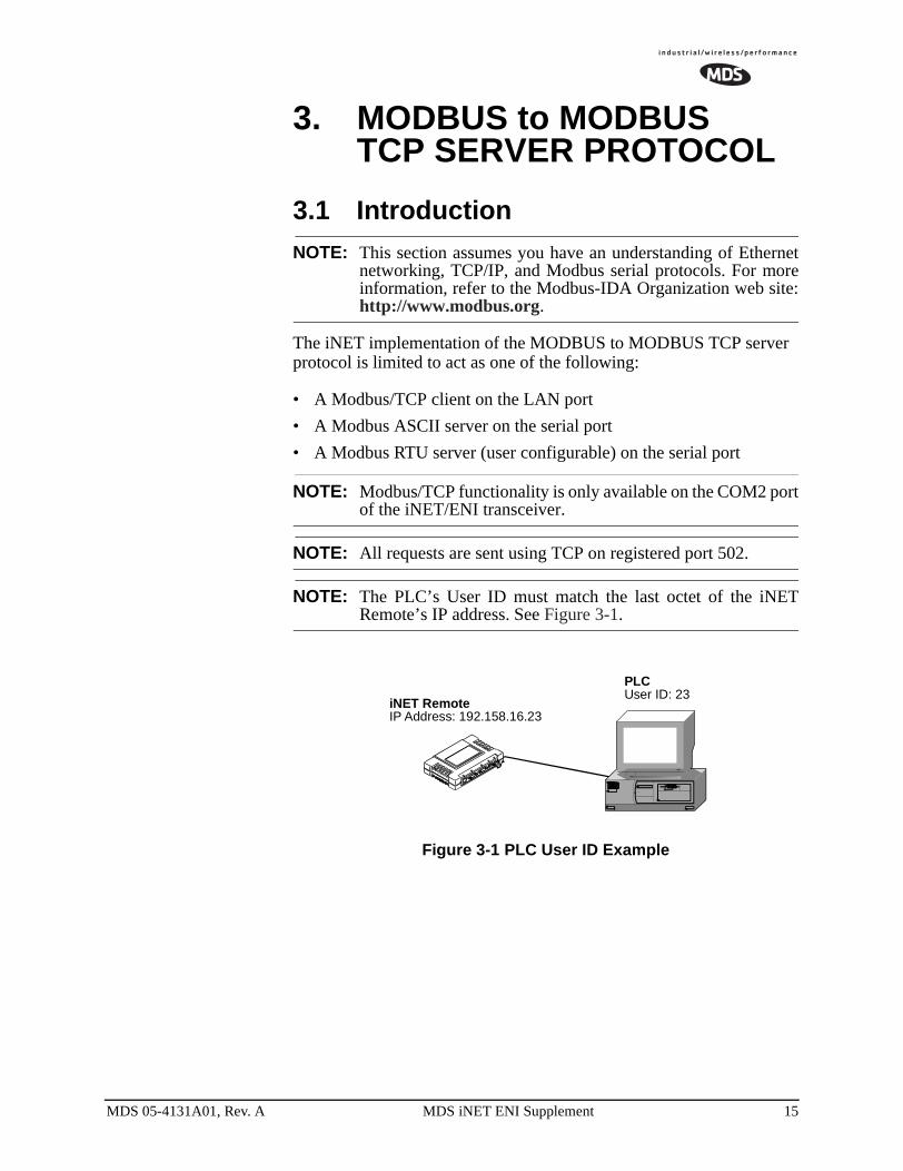
NOTE: The PLC’s User ID must match the last octet of the iNETRemote’s IP address. See Figure 3-1.
Figure 3-1 PLC User ID Example
PLCUser ID: 23
iNET RemoteIP Address: 192.158.16.23
MDS 05-4131A01, Rev. A MDS iNET ENI Supplement 15
3.2 MODBUS/TCP SERVER CONFIGURATION
Perform the following procedure to configure the MODBUS/TCP SERVER IP protocol settings:
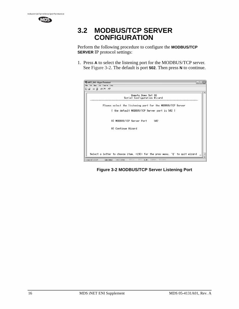
1. Press A to select the listening port for the MODBUS/TCP server. See Figure 3-2. The default is port 502. Then press N to continue.
Figure 3-2 MODBUS/TCP Server Listening Port
16 MDS iNET ENI Supplement MDS 05-4131A01, Rev. A

2. Press A to change the MODBUS serial format, then press the space bar to toggle between the available formats (MODBUS/RTU or MODBUS/ASCII). Press B to enter the MODBUS serial timeout value. See Figure 3-3. Press N to continue.
NOTE: The only difference between MODBUS/RTU andMODBUS/ASCII is the form of the framing sequence, errorcheck pattern, and address interpretation.
Figure 3-3 Choose MODBUS Serial Format and Timeout
MDS 05-4131A01, Rev. A MDS iNET ENI Supplement 17
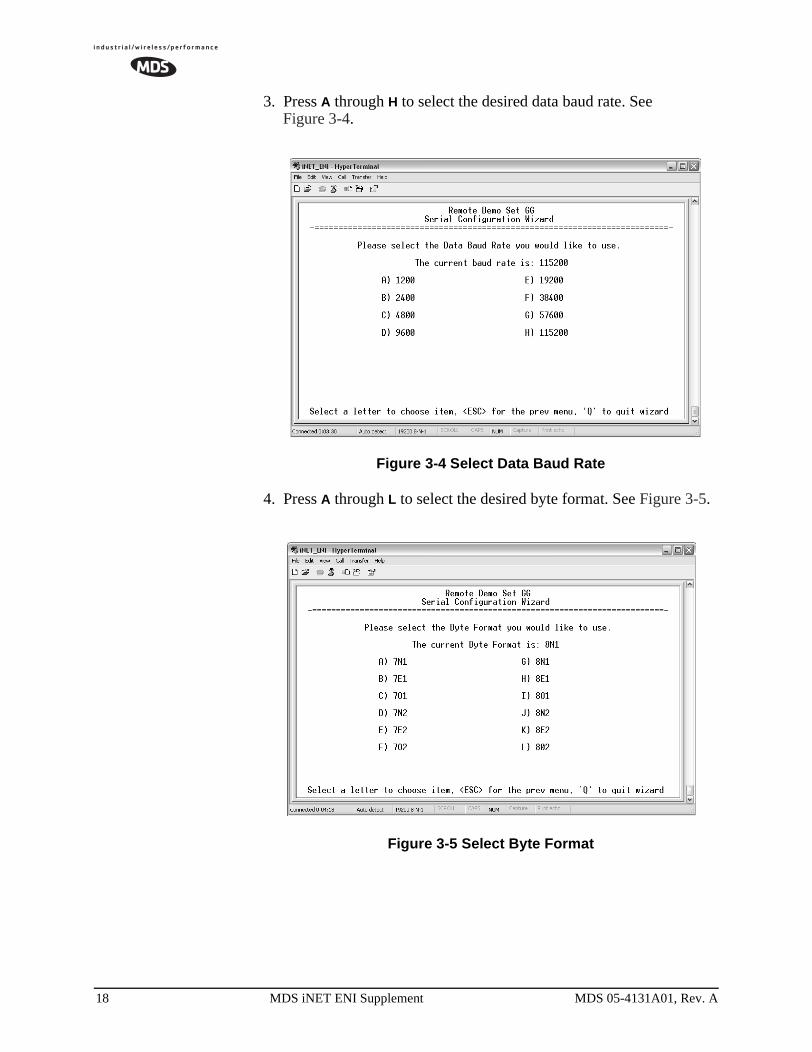
3. Press A through H to select the desired data baud rate. See Figure 3-4.
Figure 3-4 Select Data Baud Rate
4. Press A through L to select the desired byte format. See Figure 3-5.
Figure 3-5 Select Byte Format
18 MDS iNET ENI Supplement MDS 05-4131A01, Rev. A
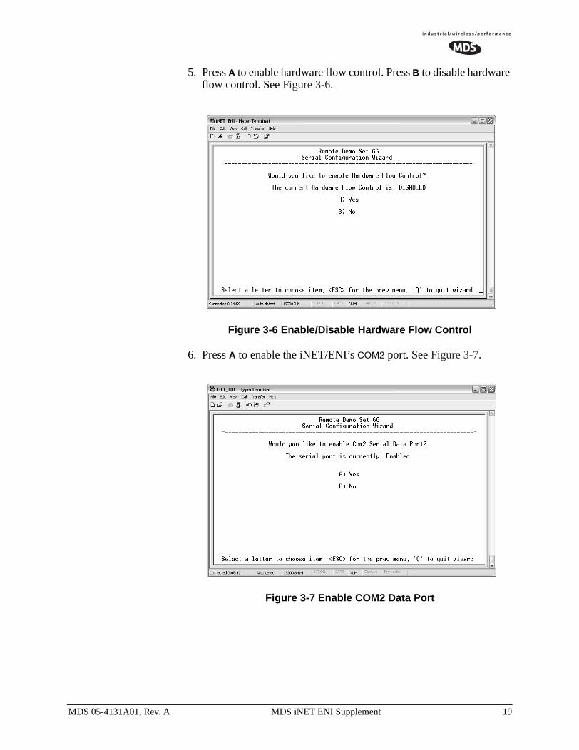
5. Press A to enable hardware flow control. Press B to disable hardware flow control. See Figure 3-6.
Figure 3-6 Enable/Disable Hardware Flow Control
6. Press A to enable the iNET/ENI’s COM2 port. See Figure 3-7.
Figure 3-7 Enable COM2 Data Port
MDS 05-4131A01, Rev. A MDS iNET ENI Supplement 19
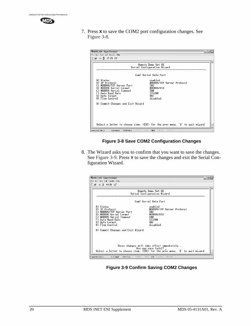
7. Press X to save the COM2 port configuration changes. See Figure 3-8.
Figure 3-8 Save COM2 Configuration Changes
8. The Wizard asks you to confirm that you want to save the changes. See Figure 3-9. Press Y to save the changes and exit the Serial Con-figuration Wizard.
Figure 3-9 Confirm Saving COM2 Changes
20 MDS iNET ENI Supplement MDS 05-4131A01, Rev. A
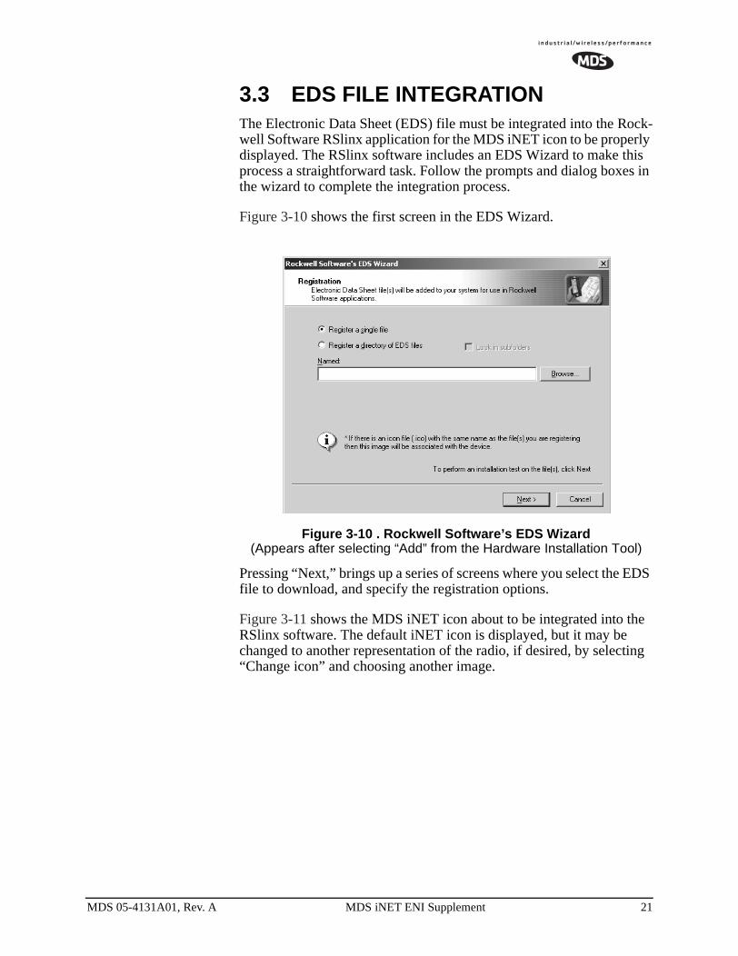
3.3 EDS FILE INTEGRATIONThe Electronic Data Sheet (EDS) file must be integrated into the Rock-well Software RSlinx application for the MDS iNET icon to be properly displayed. The RSlinx software includes an EDS Wizard to make this process a straightforward task. Follow the prompts and dialog boxes in the wizard to complete the integration process.
Figure 3-10 shows the first screen in the EDS Wizard.
Figure 3-10 . Rockwell Software’s EDS Wizard(Appears after selecting “Add” from the Hardware Installation Tool)
Pressing “Next,” brings up a series of screens where you select the EDS file to download, and specify the registration options.
Figure 3-11 shows the MDS iNET icon about to be integrated into the RSlinx software. The default iNET icon is displayed, but it may be changed to another representation of the radio, if desired, by selecting “Change icon” and choosing another image.
MDS 05-4131A01, Rev. A MDS iNET ENI Supplement 21
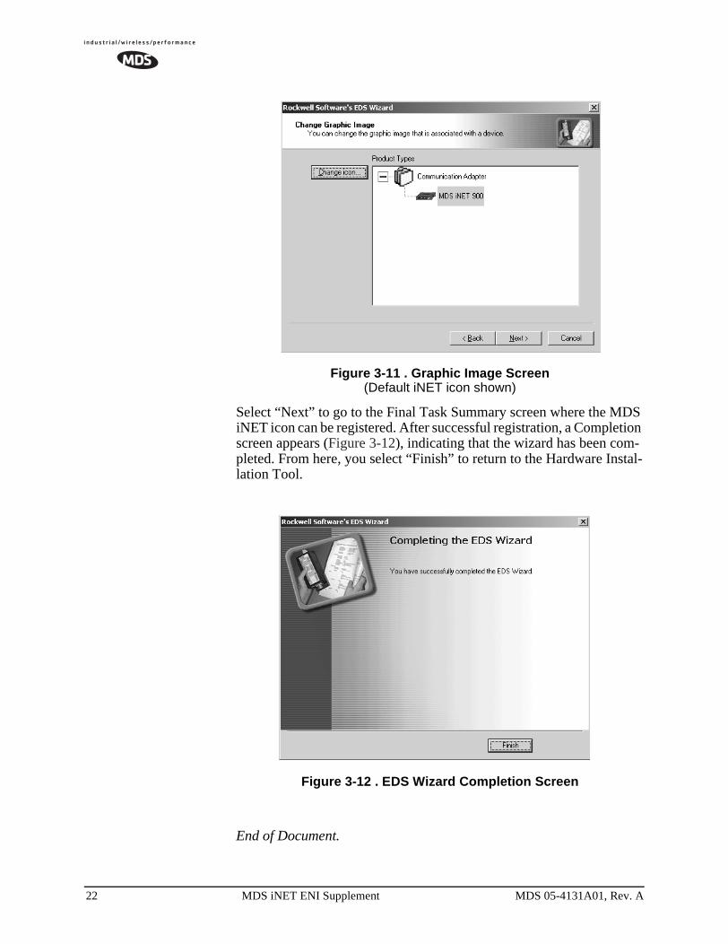
Figure 3-11 . Graphic Image Screen(Default iNET icon shown)
Select “Next” to go to the Final Task Summary screen where the MDS iNET icon can be registered. After successful registration, a Completion screen appears (Figure 3-12), indicating that the wizard has been com-pleted. From here, you select “Finish” to return to the Hardware Instal-lation Tool.
Figure 3-12 . EDS Wizard Completion Screen
End of Document.
22 MDS iNET ENI Supplement MDS 05-4131A01, Rev. A