Embed Size (px)
Citation preview

OCS Study BOEM 2014-606
User’s Guide for the 2014 Gulfwide Offshore Activities Data System (GOADS-2014)
U.S. Department of the Interior Bureau of Ocean Energy Management Gulf of Mexico OCS Region

OCS Study BOEM 2014-606
User’s Guide for the 2014 Gulfwide Offshore Activities Data System (GOADS-2014)
Authors Darcy Wilson Eastern Research Group, Inc. Morrisville, North Carolina Brian Boyer COMM Engineering, Inc. Lafayette, Louisiana
Prepared under BOEM Contract M13PC00005 by Eastern Research Group, Inc. 1600 Perimeter Park Drive Morrisville, North Carolina 27560
Published by U.S. Department of the Interior Bureau of Ocean Energy Management Gulf of Mexico OCS Region
New Orleans, LA June 2014

DISCLAIMER
This report was prepared under contract between the Bureau of Ocean Energy Management (BOEM) and Eastern Research Group, Inc. This report has been technically reviewed by BOEM, and it has been approved for publication. Approval does not necessarily signify that the contents reflect the views and policies of BOEM, nor does mention of trade names or commercial products constitute endorsement or recommendation for use.
REPORT AVAILABILITY To download a PDF file of this Gulf of Mexico OCS Region report, go to the U.S. Department of the Interior, Bureau of Ocean Energy Management, Environmental Studies Program Information System website and search on OCS Study BOEM 2014-606. This report can be viewed at select Federal Depository Libraries. It can also be obtained from the National Technical Information Service; the contact information is below.
U.S. Department of Commerce National Technical Information Service 5301 Shawnee Rd. Springfield, Virginia 22312 Phone: (703) 605-6000, 1 (800) 553-6847 Fax: (703) 605-6900 Website: http://www.ntis.gov/
CITATION
Wilson, D. and B. Boyer. 2014. User’s guide for the 2014 Gulfwide Offshore Activities Data
System (GOADS-2014). U.S. Dept. of the Interior, Bureau of Ocean Energy Management, Gulf of Mexico OCS Region, New Orleans, LA. OCS Study BOEM 2014-606. 81 pp.
iii


TABLE OF CONTENTS
Page
LIST OF FIGURES ...................................................................................................................... IX
LIST OF TABLES ........................................................................................................................ IX
1. INTRODUCTION .....................................................................................................................1 1.1 Principles of Use and System Requirements .................................................................. 1 1.2 Installation ...................................................................................................................... 1
2. USING THE 2014 GULFWIDE OFFSHORE ACTIVITIES DATA SYSTEMS (GOADS-2014) ..........................................................................................................................................3 2.1 Starting and Exiting GOADS-2014 ................................................................................ 3 2.2 Creating and Editing Data ............................................................................................ 11
2.2.1 Creating and Editing Structure Data ............................................................... 11 2.2.2 Creating and Editing Equipment Data ............................................................ 16
2.3 Quality Control Tests ................................................................................................... 18 2.4 Saving and Backing up Work ....................................................................................... 19 2.5 Setting Status of Facilities and Equipment................................................................... 19 2.6 Finding Help and Extra Information ............................................................................ 20
3. UPON SURVEY COMPLETION ...........................................................................................21 3.1 How, When, and Where to Deliver Data Files ............................................................. 21 3.2 Failed Quality Control Tests ........................................................................................ 21 3.3 QA Summary Form ...................................................................................................... 21
4. HELP TEXT FILES .................................................................................................................23 4.1 User Information .......................................................................................................... 23
4.1.1 General Information Tab................................................................................. 23 4.2 Structure Information ................................................................................................... 24
4.2.1 General Information Tab................................................................................. 24 4.2.2 Sales Gas Data ................................................................................................ 25 4.2.3 QC Results Tab ............................................................................................... 25
4.3 Amine Gas Sweetening Unit ........................................................................................ 26 4.3.1 General Information Tab................................................................................. 26 4.3.2 Model Inputs Tab ............................................................................................ 26 4.3.3 Ventilation System Tab for Acid Gas from the Reboiler ............................... 27 4.3.4 Control Equipment Tab................................................................................... 28 4.3.5 QC Results Tab ............................................................................................... 29
4.4 Boiler/Heater/Burner .................................................................................................... 30 4.4.1 General Information Tab................................................................................. 30 4.4.2 Exhaust System Tab ........................................................................................ 31 4.4.3 Control Equipment Tab................................................................................... 31 4.4.4 QC Results Tab ............................................................................................... 32
4.5 Diesel or Gasoline Engine ............................................................................................ 33
v

4.5.1 General Information Tab................................................................................. 33 4.5.2 Exhaust System Tab ........................................................................................ 34 4.5.3 Control Equipment Tab................................................................................... 34 4.5.4 QC Results Tab ............................................................................................... 35
4.6 Drilling Equipment ....................................................................................................... 36 4.6.1 General Information Tab................................................................................. 36 4.6.2 Exhaust System Tab ........................................................................................ 36 4.6.3 Control Equipment Tab................................................................................... 36 4.6.4 QC Results Tab ............................................................................................... 37
4.7 Combustion Flare ......................................................................................................... 38 4.7.1 General Information Tab................................................................................. 38 4.7.2 QC Results Tab ............................................................................................... 39
4.8 Fugitives ....................................................................................................................... 40 4.8.1 General Information Tab................................................................................. 40 4.8.2 QC Results Tab ............................................................................................... 42
4.9 Glycol Dehydrator Unit ................................................................................................ 43 4.9.1 General Information Tab................................................................................. 43 4.9.2 Ventilation System Tab – For Still Column Vent Only .................................. 44 4.9.3 Control Equipment Tab................................................................................... 45 4.9.4 QC Results Tab ............................................................................................... 45
4.10 Loading Operation ........................................................................................................ 46 4.10.1 General Information Tab................................................................................. 46 4.10.2 Ventilation System Tab................................................................................... 46 4.10.3 Control Equipment Tab................................................................................... 47 4.10.4 QC Results Tab ............................................................................................... 47
4.11 Losses From Flashing ................................................................................................... 48 4.11.1 General Information Tab................................................................................. 48 4.11.2 Ventilation System Tab................................................................................... 48 4.11.3 QC Results Tab ............................................................................................... 49
4.12 Mud Degassing ............................................................................................................. 50 4.12.1 General Information Tab................................................................................. 50 4.12.2 QC Results Tab ............................................................................................... 50
4.13 Natural Gas Engine ...................................................................................................... 51 4.13.1 General Information Tab................................................................................. 51 4.13.2 Exhaust System Tab ........................................................................................ 52 4.13.3 Control Equipment Tab................................................................................... 52 4.13.4 QC Results Tab ............................................................................................... 52
4.14 Natural Gas, Diesel, or Dual Fuel Turbine ................................................................... 53 4.14.1 General Information Tab................................................................................. 53 4.14.2 Exhaust System Tab ........................................................................................ 54 4.14.3 Control Equipment Tab................................................................................... 55 4.14.4 QC Results Tab ............................................................................................... 55
4.15 Pneumatic Pumps ......................................................................................................... 56 4.15.1 General Information Tab................................................................................. 56 4.15.2 Ventilation System Tab................................................................................... 56 4.15.3 QC Results Tab ............................................................................................... 56
vi
4.16 Pressure/Level Controllers ........................................................................................... 58
4.16.1 General Information Tab................................................................................. 58 4.16.2 QC Results Tab ............................................................................................... 58
4.17 Storage Tank................................................................................................................. 59 4.17.1 General Information Tab................................................................................. 59 4.17.2 Ventilation System Tab................................................................................... 60 4.17.3 Control Equipment Tab................................................................................... 61 4.17.4 QC Results Tab ............................................................................................... 61
4.18 Cold Vent ..................................................................................................................... 62 4.18.1 General Information Tab................................................................................. 62 4.18.2 Control Equipment Tab................................................................................... 63 4.18.3 QC Results Tab ............................................................................................... 63
5. GOADS-2014 QA SUMMARY FORM DATA FIELDS .......................................................65
vii


LIST OF FIGURES
Page
Figure 1. Populating GOADS-2014. .......................................................................................... 4
Figure 2. New User screen. ........................................................................................................ 5
Figure 3. GOADS-2014 main window. .................................................................................... 6
Figure 4. GOADS-2014 main menu. ......................................................................................... 8
Figure 5. GOADS-2014 help menu. .......................................................................................... 8
Figure 6. GOADS-2014 import screen. ................................................................................... 10
Figure 7. GOADS-2014 export screen. .................................................................................... 11
Figure 8. New structure dialog box. ......................................................................................... 12
Figure 9. Structure screen in description edit mode. ................................................................ 13
Figure 10. Structure screen in activity edit mode. ..................................................................... 14
Figure 11. Sales gas screen. ....................................................................................................... 15
Figure 12. New equipment dialog box. ...................................................................................... 17
Figure 13. QC results tab. .......................................................................................................... 19
Figure 14. QA Summary Form screen. ...................................................................................... 22
LIST OF TABLES
Page
Table 1. Default Sales Gas Composition ................................................................................. 15
Table 2. Speciation Fractions for Total Hydrocarbon (THC) Emissions by Stream Type ...... 40
Table 3. Summary of Equipment Inventory Data (Number of Components) by Skid Type ... 41
Table 4. GOADS-2014 QA Summary Form Equipment Type Codes ..................................... 66
Table 5. GOADS-2014 QA Summary Form Data Fields ........................................................ 67
ix

1. INTRODUCTION The Bureau of Ocean Energy Management (BOEM), formerly Minerals Management
Service, mandated that offshore operators in the Gulf of Mexico participate in an annual survey program for the years 2000, 2005, 2008, and 2011. BOEM collected emissions information related to offshore operations to establish the Gulf Wide emission inventory. For the 2000, 2005, 2008, and 2011 inventory efforts, BOEM Gulfwide Offshore Activities Data System (GOADS) software was provided in order to assist offshore operators in complying with the BOEM mandate. The GOADS software assists users in recording information regarding emissions-related offshore activities and generates data files that can be delivered to BOEM. For calendar year 2014, BOEM will again provide a new improved version of the software, GOADS-2014.
The primary differences between the GOADS-2014 and the GOADS-2011 is that users must enter activity information for all oil and gas production platforms (i.e., you can no longer simply flag platforms as minor sources), Loading Operations have been added, and a ventilation system tab has been added for Drilling Rigs. Other revisions focused on programming errors associated with the QC checks and QA Summary Form checks. Like the GOADS-2011 data collection effort, the reported monthly GOADS-2014 volume vented and flared data must be consistent with the information provided to the Office of Natural Resources Revenue (ONRR) Oil and Gas Operations Report (OGOR) forms, including data reported based on metered volumes. As with previous data collection efforts, the GOADS-2014 the QA Summary Form must be submitted with the activity data file(s).
1.1 PRINCIPLES OF USE AND SYSTEM REQUIREMENTS The GOADS-2014 requires an IBM-compatible personal computer (PC) equipped with the
Microsoft® Windows® XP, Windows® Vista, or Windows® 7 and 8 operating systems. The user should possess a modest familiarity with the Windows® operating environment and should understand a few of its common features, such as point-and-click, file management, menu-driven selection, and text boxes.
1.2 INSTALLATION The GOADS-2014 website includes the User’s Guide, Installation Guide, lookup tables with
BOEM information such as operator IDs and other structure data, and the GOADS2014 SETUP.EXE file.
To install GOADS-2014, follow the steps below:
1. Download the GOADS2014 SETUP.EXE file from the Internet and copy it to your hard drive.
2. From My Computer, double click on the file GOADS2014SETUP.EXE.
3. Follow the instructions that appear on each successive screen. You will be asked to select a folder on your computer where GOADS-2014 will be installed. The default and recommended location is C:\Program Files\GOADS2014\. However, with Windows® Vista and Windows 7/8, the
1

C:\Program Files\ directory structure is secured and files that are updated by software applications such as GOADS-2014 need to be located in a different location on your computer. For users running Windows® Vista or Windows® 7/8, it is recommended that you select a database folder within your User folder.
4. After you have identified the location where GOADS-2014 should be installed, click Finish to complete the installation.
During the installation process, the setup program may ask you to reboot your machine one or more times (depending upon the files currently installed on your PC). You should reboot when asked.
If you encounter any problems during installation of GOADS-2014, please contact Ms. Holli Ensz, BOEM, [email protected], (504) 736-2536.
5. The GOADS database should be backed up periodically by copying to a secure location. The name of this file is GOADS.MDB, and it will be in the folder where you installed GOADS. If you create other GOADS databases, the GOADS.MDB file will be in the folder where you created it.
6. If you plan to have several people in your organization performing data entry, install GOADS on each of their computers, then have one person “Create New GOADS Database” on a shared file server. Each person performing data entry will then open that shared database using the “Open a Different GOADS Database” option on the file menu.
7. If you are a contractor doing data entry for multiple operators, use the “Create New GOADS Database” option on the File menu to create separate databases for each operator. You should give each new folder a name that will allow you to easily identify it when you are opening it.
8. When supplying your activity data, if you do NOT select No Emissions to Report BOEM will assume that the platform or equipment is operating that month, and surrogate data will be used to develop emission estimates if necessary. BOEM will also assume that activity values that are left blank (Null) should be populated with surrogate data.
2

2. USING THE 2014 GULFWIDE OFFSHORE ACTIVITIES DATA SYSTEMS (GOADS-2014)
The GOADS-2014 software helps users complete monthly surveys of air emissions-related activities that are associated with offshore facilities. GOADS-2014 queries the user regarding emissions-related operating data, saves the data on the user’s PC, and guides the user to create copies of the data for backup or delivery to BOEM. Figure 1 describes the steps in populating the GOADS-2014 database.
• You should run GOADS-2014 to enter new operating data for each month. For example, if production or throughput volumes change from month-to-month, this new information should be entered for every month. Parameters that remain constant do not need to be entered every month.
• A saved data set corresponding to one month is called a “survey” or a “monthly survey.” When you create a survey, you should enter information that represents your offshore facility and all emissions-producing equipment on the facility. GOADS-2014 provides a fill-in-the-blank approach to generate structure, equipment, and production/throughput data.
• As you enter data, GOADS-2014 performs a number of automatic error checks. If an error is suspected, you will be reminded and may be asked to correct the error or provide comments in a text box. After the data are submitted, BOEM will attempt to reconcile missing or unusual data by reviewing the comments or contacting you by telephone. GOADS-2014 performs the following types of error checks:
Completeness: to identify missing data entries
Range: to determine when data entries fall outside of typical ranges
Consistency: to determine whether data entries are consistent with one another
Month-to-month: to determine whether information that typically varies by month has been reviewed and edited appropriately or to flag items that change radically from one month to the next
2.1 STARTING AND EXITING GOADS-2014
To open the Start menu, click the Start button in the lower-left corner of your screen. Or
press the Windows® logo on your keyboard. Upon starting GOADS-2014 for the first time, the “New User” screen will appear (Figure 2). At this point you must fill in the requested contact information in order to proceed. You will be able to revise this information if necessary each time the Main Window (Figure 3) appears.
3

Figure 1. Populating GOADS-2014.
Start Program
Add New Equipment Records
Input BOEM
Company No., etc.
Install GOADS-2014
Input Inventory Year (2014)
Import GOADS-2011 Structure Data
Enter/Edit New
Structure Descriptive
Data
Enter Monthly
Structure Activity Data
Enter Sales Gas Data
Run QC Checks,
Correct Data
Enter/Edit Equip
ment Descriptive
Data
Enter Monthly
Equipment Activity Data
Flag Inoperable Equipment
Run QC Checks,
Correct Data
Review QA Summary
Forms, Correct
Data
Email Data Files to BOEM
4

Figure 2. New User screen.
The “New User” screen asks for “BOEM Company No.” It is extremely important that you use the correct BOEM Company Number. It can be found in a separate file posted with the program and User’s Guide. This ID cannot be changed once entered. The inventory year is 2014.
5

Figure 3. GOADS-2014 main window.
The GOADS-2014 program has a feature that distinguishes between static (descriptive) and
dynamic (activity) data. This feature is designed to reduce data entry time by requesting static platform and equipment data only once (rather than every month). The title bar at the top of the screen indicates the current edit mode. When you select Edit > Change to Description Edit Mode from the main menu, or Edit Description Data on the lower left side of any screen, the program allows you to enter or edit data that do not change from month to month. To edit the descriptive data, select Edit Data on the lower right side of any screen.
When you select Edit > Change to Activity Edit Mode from the main menu, or Edit Activity Data on the lower left side of any screen, the program allows you to enter or edit monthly activity data that are likely to change from month to month. In this mode you see the descriptive data, but it cannot be edited. Edit the activity data, select Edit Data on the lower right side of any screen.
6

From the Main Window (Figure 4), you may perform the following tasks:
• Export or import GOADS-2014 files. GOADS-2011 platform and equipment descriptions will also be made available as GOADS-2011 import files.
• Edit user identification information (initially entered during program installation).
• View, create new, edit, save, or delete data for monthly surveys, facilities, or equipment.
• Run QC on a selected monthly survey, platform, or piece of equipment.
• Export the structure or equipment descriptions to a spreadsheet. (You must first save and exit GOADS-2014 and re-open the program for this feature to work.)
• Print the current screen.
• Directly access the BOEM GOADS Internet Site with Frequently Asked Questions (FAQs) and this User’s Guide (Figure 5).
• Export a saved monthly survey or entire annual database to CD for backup or delivery to BOEM.
• Export the QA Summary Form (must be provided when file is submitted to BOEM; highlights key data elements that are missing) (see Section 3.3).
7

Figure 4. GOADS-2014 main menu.
Figure 5. GOADS-2014 help menu.
8

Use one of the following two ways to exit the program: (1) click File | Exit Program from
the Main Window menu, or (2) click the symbol at the upper right to close the program window.
If you have never used GOADS-2011, you can skip this section and go directly to Section 2.2 “Creating and Editing Data.” If you have used GOADS-2011, you should read this section before proceeding.
If you were a GOADS-2011 user, you can request your GOADS-2011 platform and equipment descriptive data from BOEM by sending an email request to: [email protected]. Do not use the “Open a different GOADS database” menu option to open a GOADS-2011 database. Updates have been made in underlying GOADS-2014 database structure that will cause program errors if you attempt to open a 2011 file.
You can then import the GOADS-2011 descriptive data file supplied by BOEM into GOADS-2014 before proceeding (described below). This descriptive data may be slightly different from your original submittal to BOEM; it has undergone extensive QA/QC by BOEM and may have been adjusted as a result. You can and must edit the descriptive data after importing it to reflect any structural or equipment changes since 2011.
GOADS-2014 has a platform data import or export feature. The 2011 data are provided in this format so that they may be imported as if they had been exported in the same format.
To import the GOADS-2011 data, select File|Import GOADS-2014 Structure data. (Named as such because the 2011 data are in the GOADS-2014 required structure.) A dialog box will appear which lists any descriptive data that have been previously imported. The first time you import a file, this list will be blank. Enter the path and file name of the GOADS-2011 file you want to import in the box labeled “Import File Path and Filename.” You can also use the “Browse” button to find the file you wish to import (Figure 6). After you have selected a file, select Import Selected Structures . The GOADS-2011 file will be imported as January 2014 (this may take a few seconds). When the import process is complete, the survey name and its associated structures and equipment types should appear in the Navigation tree on the left of the screen. You must repeat this import process for all of your GOADS-2011 files (if you received multiple 2011 files).
9

Figure 6. GOADS-2014 import screen.
You can also use the File|Import GOADS-2014 Structure data feature to upload data for a
structure that has been purchased in 2014 from another company. The User ID in the imported file will automatically be updated to your User ID. This process will import descriptive and monthly activity data, as available. The previous operator of that structure uses the corresponding File|Export GOADS-2014 Structure data to create this file (Figure 7).
10

Figure 7. GOADS-2014 export screen.
2.2 CREATING AND EDITING DATA
2.2.1 Creating and Editing Structure Data
To create new structure data, from the Description Edit Mode, select Edit | New Structure from the Main Window menu.
11

A New Structure Dialog Box will appear to request vital identification data for the structure
(Figure 8). See Section 4 for guidance on entering these data correctly.
Figure 8. New structure dialog box.
Enter the information and click OK . An icon for the new structure will appear in the
Navigation Tree on the left side of the Main Window. Highlight the new structure icon to view the Structure Screen.
Figures 9 and 10 show the Structure screen in Description Edit Mode and Activity Edit Mode.
In the Description Edit Mode, the Structure Screen contains three tabs: General Information, Sales Gas, and QC Results. General Information shows contact and other general information for the current structure. Note that production is the quantity of petroleum that was extracted from the ground at the structure; throughput is the total quantity of petroleum handled at the structure, including petroleum extracted at another location and transferred to the structure. Sales Gas presents the volumetric composition of the natural gas processed at the structure and transferred off the structure (Figure 11). QC Results tabulates any quality control errors that may be encountered as data are completed for the current structure and its associated equipment (see Section 2.3). In the Activity Edit Mode, the Sales Gas tab is not visible because it contains data that do not change from month to month. If the Sales Gas information is not provided, the default values listed in Table 1 will be applied during emissions calculation.
12

Figure 9. Structure screen in description edit mode.
13
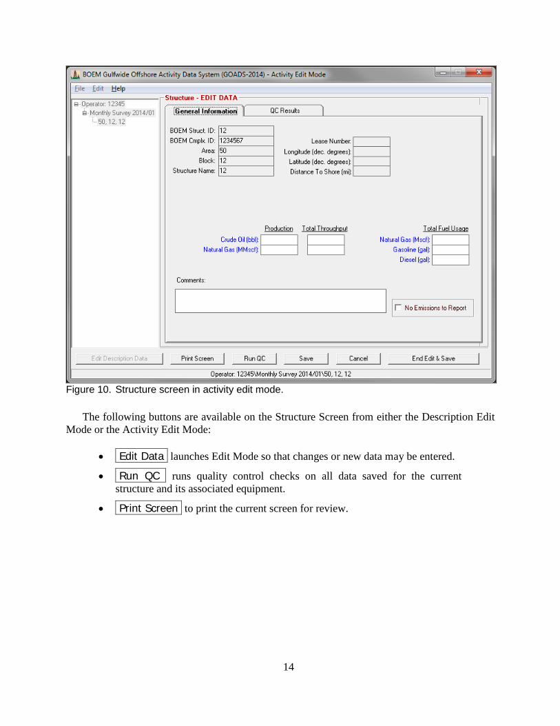
Figure 10. Structure screen in activity edit mode.
The following buttons are available on the Structure Screen from either the Description Edit Mode or the Activity Edit Mode:
• Edit Data launches Edit Mode so that changes or new data may be entered.
• Run QC runs quality control checks on all data saved for the current structure and its associated equipment.
• Print Screen to print the current screen for review.
14

Figure 11. Sales gas screen.
Table 1.
Default Sales Gas Composition
Component Default Mol% Mole Weight (lb/lb-mole)
CO2 0.80 44.010 CH4 94.50 16.043 C2H6 3.33 30.070 C3 Hydrocarbons 0.75 44.097 i-C4 Hydrocarbons 0.15 58.124 n-C4 Hydrocarbons 0.15 58.124 i-C5 Hydrocarbons 0.05 72.150 n-C5 Hydrocarbons 0.05 72.150 C6 Hydrocarbons 0.099 86.177 C7 Hydrocarbons 0.011 100.272 C8+ Hydrocarbons 0.007 114.231
15

Four additional buttons become available in the Activity Edit Mode:
• Save (only available in Edit Mode) incrementally saves work and returns to
Edit Mode.
• Cancel (only available in Edit Mode) discard recent changes and close Edit Mode.
• End Edit & Save (only available in Edit Mode) saves changes and exits Edit Mode.
• No Emissions to Report to flag a structure as inactive for a given month.
From the Activity Edit Mode, new monthly surveys can be created. An icon for the new
survey will appear in the Navigation Tree on the left side of the Main Window. Previously entered equipment descriptive data (see Section 2.2.2) will automatically be copied into the new monthly survey. Highlight the survey icon to view the Survey Screen. The Survey Screen contains only one tab: QC Results. QC Results tabulates any quality control errors encountered during data entry (see Section 2.3).
2.2.2 Creating and Editing Equipment Data GOADS-2014 queries for information regarding the following sources of emissions:
• Amine gas sweetening unit
• Boiler/heater/burner
• Drilling rig
• Combustion flare
• Fugitive losses
• Gasoline/diesel engine
• Glycol dehydrator
• Loading Operation
• Losses from flashing
• Mud degassing
• Natural gas engine
• Natural gas, diesel, or dual-fuel turbine
• Pneumatic pumps
• Pressure/level controllers
• Storage tank
• Cold vent
16

To create new equipment data, go to the Navigation Tree on the left side of the Main
Window and select the appropriate structure (into which the new equipment data will be placed). Select Edit | New Equipment from the Main Window menu.
A New Equipment Dialog Box will request vital identification data for the equipment, such as equipment ID number and equipment type (e.g., flares, turbines, etc.) (Figure 12). Enter the information, then click OK . An icon for the new equipment will appear in the Navigation Tree on the left side of the Main Window and a new screen will automatically open, specific to the equipment type entered. You can return to this equipment screen at any time by highlighting the equipment.
Figure 12. New equipment dialog box.
Depending on the equipment type and the edit mode, the equipment screen will contain two
to four tabs: General Information, Exhaust/Ventilation System, Control Equipment, and QC Results. General Information shows operating parameters for the current equipment. From the Description Edit Mode, you can populate or edit static equipment description data that do not change from month to month. When you create a new monthly survey, these data are automatically copied. From the Activity Edit Mode, you are prompted to enter activity data that can vary from month to month. These data are not copied automatically when a new monthly survey is created.
Exhaust/Ventilation System presents variables that are related to equipment exhaust systems; this screen is not visible when you are in Activity Edit Mode. Control Equipment permits users to describe installed pollution control devices that were not accounted for on the General Information tab; this screen is also not visible when you are in Activity Edit Mode. QC Results
17

tabulates any quality control errors that may be encountered as data are completed for the equipment (see Section 2.3).
In Edit Activity Data you can select No Emissions to Report for a given month for the entire platform or specific pieces of equipment. This is an important new feature; BOEM will assume that the platform or equipment are NOT operating for months flagged as such, regardless of other values that may be populated for the month. The user does not have to fill in the forms with zeros for inactive structures or equipment, merely check this box. Records flagged as no emissions to report will not be QC checked in the inventory development process.
If you do NOT select No Emissions to Report , BOEM will assume that the platform or
equipment is operating that month, and surrogate data will be used to develop emission estimates if necessary.
BOEM will also assume that activity values that are left blank (Null) should be populated
with surrogate data. The following buttons are available on the Description Edit Mode and Activity Edit Mode
Equipment Screens: Activity values that are populated with zeros will NOT be populated with surrogate data.
• Edit Data launches Edit Mode so that changes or new data may be entered.
• Run QC runs quality control checks on data for the current equipment.
• Print Screen to print the current screen for review.
Four additional buttons become available only in Activity Edit Mode:
• Save (only available in Edit Mode) incrementally saves work and returns to Edit Mode.
• No Emissions to Report to flag equipment as inactive for a given month.
• Cancel (only available in Edit Mode) discard recent changes and close Edit Mode.
• End Edit & Save (only available in Edit Mode) saves changes and exits Edit Mode.
2.3 QUALITY CONTROL TESTS After you complete and save data, GOADS-2014 automatically runs a series of quality
control (QC) checks before saving the data. If any entries are incomplete, atypical, or suspect, a pop-up message will appear, and a list of QC errors will appear on the QC Results tab (Figure 13). You may choose to return and correct the problems, to override QC check(s) (a comment is required), or to ignore message(s) and save changes anyway. If QC problems remain uncorrected and uncommented when the data are submitted, BOEM staff will attempt to reconcile missing, atypical, or suspect data by reviewing the comments or contacting you.
18

Figure 13. QC results tab.
2.4 SAVING AND BACKING UP WORK
It is very important to periodically store data to a secure location other than the hard drive (such as a CD). This minimizes data loss in the event of a computer failure or other mishap.
After you complete and save data, the entries are saved to a working file on the hard drive.
(To discard changes, click Cancel instead of End Edit & Save .) To store data in an alternate location, select File|Export GOADS-2014 Inventory Database on the main menu. A dialog box will appear which will allow you to enter a File Path and Filename or browse to the location in which you wish to create the file. After entering the path and file name, hit “OK.” You can then copy the file you have created to CD or zip disk.
2.5 SETTING STATUS OF FACILITIES AND EQUIPMENT If equipment or an entire structure becomes inactive for an entire monthly survey period, the
change in status should be noted by selecting No Emissions to Report but only for the affected survey period(s). Note that when a piece of equipment or a structure is active for any part of a survey period, its status should NOT be set to No Emissions to Report.
19

Open an affected survey in the Navigation Tree on the left side of the Main Window.
(Double-click the survey icon, or click the + symbol immediately to its left.) Select the affected structure or equipment, and click Edit Data in order to launch Edit Mode. Use the Set Status data entry boxes to change the status. Indicate the new status and its effective date and click End Edit & Save in order to record the change in status.
2.6 FINDING HELP AND EXTRA INFORMATION Each screen has an associated help text file that contains technical details about the required
data entries, such as definitions, quality control checks, typical values, estimation methods, etc. Access help by pressing the F1 key. You can also go to the Help menu and select “current screen” to view the help file for the current screen or select “other screen” and see a list of all available help files. Help files are reprinted in Section 4 of this User’s Guide. In addition, you can directly access the BOEM GOADS Internet Site with Frequently Asked Questions (FAQs) and this User’s Guide from within GOADS-2014.
20

3. UPON SURVEY COMPLETION
3.1 HOW, WHEN, AND WHERE TO DELIVER DATA FILES When the entire inventory is completed (12 monthly surveys), it should be exported to your
hard-drive for submittal to BOEM. To export the inventory, select File|Export GOADS-2014 Inventory Database on the main menu. A dialog box will appear which will allow you to enter a File Path and Filename or browse to the location in which you wish to create the file. After entering the path and file name, click “OK.” You can then copy the file you have created to the appropriate medium for your internal file storage.
Files must be submitted to BOEM electronically through the following email address:
[email protected]. BOEM should receive all 2014 data files before April 15, 2015.
3.2 FAILED QUALITY CONTROL TESTS When saving the file for delivery to BOEM, GOADS-2014 stores the results of all QC tests.
If the user returns to GOADS-2014 in order to address QC problems, the error messages may be reviewed from the QC Results tab on the Survey Screen. If you choose to ignore errors and submit the data anyway, BOEM staff will attempt to reconcile the problems by reviewing comments or contacting you.
3.3 QA SUMMARY FORM From the Main Window (Figure 4), the File | Export Annual Inventory QA Summary
Form may be selected at any time to view and obtain an Adobe file of key missing and inconsistent data elements (Figure 14). These data elements are critical if BOEM is to develop emission estimates for the equipment listed. The QA Summary Form Adobe file must be submitted with your data files to facilitate review by BOEM staff. Section 5 presents the key data elements in the QA Summary Form.
21
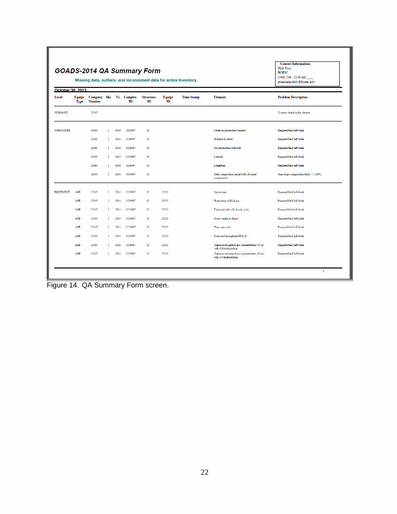
Figure 14. QA Summary Form screen.
22

4. HELP TEXT FILES
4.1 USER INFORMATION
4.1.1 General Information Tab GOADS-2014 Registered User: Identifies the person to whom GOADS-2014 is registered, an employee of the company that owns or operates structures in the Outer Continental Shelf. This should be the primary contact person who is responsible for submitting surveys to BOEM. The following contact information should be provided:
• Name
• Phone number
• Fax number
• Email address
• Company name
• Street address
• City
• State
• Zip code
23

4.2 STRUCTURE INFORMATION
4.2.1 General Information Tab BOEM Structure ID: A unique identifier code that is assigned to an offshore structure prior to its construction by BOEM. This identifier code is tracked in BOEM’s records. BOEM Complex ID: A unique identifier code that is assigned to a group of related structures prior to construction by BOEM. This identifier code is tracked in BOEM records. Area Name: Designated name of the geographic area in which the structure is located. Block Number: Designated number of the geographical block in which the structure is located. Name: A name or identifier that denotes a structure within its Area/Block. Lease Number: The lease number issued by BOEM for the construction and operation of an offshore structure. Longitude (decimal degrees): An east-west coordinate that defines the position of an offshore structure. Specify to at least four decimal places. Latitude (decimal degrees): A north-south coordinate that defines the position of an offshore structure. Specify to at least four decimal places. Distance to shore (miles): The distance to the nearest U.S. shoreline. Specify to the nearest 1/10 mile. Production: Describes the natural gas or oil products that were extracted at this structure during the specific survey period.
• Crude Oil Production (barrels): The quantity of crude oil extracted at this structure.
• Natural Gas Production (million standard cubic feet): The quantity of natural gas extracted at this structure, volume adjusted to standard temperature and pressure (60 degrees Fahrenheit, 1 atmosphere).
Throughput: The total volume of natural gas or oil products handled at the current structure during the survey period, including production volumes and volumes transferred by pipeline from another location.
• Crude Oil Throughput (barrels): The total quantity of crude oil handled at the current structure.
24

• Natural Gas Throughput (million standard cubic feet): The total quantity of
natural gas handled at the current structure, volume adjusted to standard temperature and pressure (60 degrees Fahrenheit, 1 atmosphere).
Total fuel usage: The quantity of fuel consumed at this structure during the specific survey period.
• Natural gas fuel usage (thousand standard cubic feet): The quantity of natural gas consumed at this structure.
• Gasoline usage (gallons): The quantity of gasoline consumed at this structure.
• Diesel fuel usage (gallons): The quantity of diesel fuel consumed at this structure.
No Emissions to Report: Indicates the status of the structure for the specific survey period.
“No Emissions to Report”: Indicates that the structure and all of its equipment were unused for the entire month-long survey period. The Enter Edit Mode button will be disabled for all equipment belonging to the structure, and all equipment will be treated as inactive.
Comments: A space for general user comments about this structure, with a maximum length of 255 characters.
4.2.2 Sales Gas Data Sales Composition (mole percent): The volumetric composition (percent by volume = mole percent) of the natural gas processed at the structure and transferred off the structure. If a constituent is not present, enter 0. The composition should sum to 100%.
4.2.3 QC Results Tab Error Source: List of input variables, structures, and equipment for this survey that have been flagged with QC error messages. Error Description: List of the reasons that QC error messages were assigned. Operator Comment: List of user’s explanations for unusual or unexpected values that were flagged with QC error messages. An operator comment indicates that the user wishes to override the QC error message. (To add Operator Comments, select an error message, then click “Add QC Comment”.)
25

4.3 AMINE GAS SWEETENING UNIT
4.3.1 General Information Tab Processed throughput (million standard cubic feet): The total volume of natural gas processed by this amine unit during the specific monthly survey period, volume adjusted to standard temperature and pressure (60 degrees Fahrenheit, 1 atmosphere). Hours operated: The total number of hours that this amine unit was in operation during the specific monthly survey period. Unprocessed natural gas concentrations (percent by volume): The volumetric concentrations of constituents present in the unprocessed natural gas stream, including the following:
• Hydrogen Sulfide
• Methane (CH4)
• Ethane (C2H6)
• C3 Hydrocarbons (hydrocarbons with 3 carbon atoms in their molecular structure)
• C4 Hydrocarbons
• C5 Hydrocarbons
• C6 Hydrocarbons
• C7 Hydrocarbons
• C8+ Hydrocarbons (hydrocarbons with 8 or more carbon atoms in their molecular structure)
Specify emissions by model inputs. Proceed to the model inputs screen.
4.3.2 Model Inputs Tab Amine type: Indicates the type of amine used in this unit, monoethanolamine (MEA), diethanolamine (DEA), tertiaryethanolamine (TEA), methyldiethanolamine (MDEA), diglycolamine (DGA). Unprocessed sour gas feed pressure (pounds per square inch gauge): The pressure of the unprocessed sour gas feed. Unprocessed sour gas feed temperature (degrees Fahrenheit): The temperature of the unprocessed sour gas feed. Equipped with a flash tank? (yes/no): Indicates whether the system is equipped with a flash tank. Flash tank temperature (degrees Fahrenheit): The temperature of the flash tank.
26

Flash tank pressure (pounds per square inch gauge): The pressure of the flash tank. Destination of flash gas: Indicates if the gas is vented to the atmosphere, routed to a separator, recycled to an absorber, or burned in a flare. Number of absorber trays: Indicates the number of absorber trays on this amine unit. Lean amine feed pressure (pounds per square inch gauge): The pressure of the lean amine feed. Lean amine feed temperature (degrees Fahrenheit): The temperature of the lean amine feed. Lean amine volumetric flowrate (gallons per minute): The rate of amine circulation through the unit. Lean amine feed amine content (percent by weight): The amine content of the lean amine feed. Lean amine feed H2S concentration (percent by volume): The volumetric concentration of H2S present in the lean amine feed. Lean amine feed CO2 concentration (percent by volume): The volumetric concentration of CO2 present in the lean amine feed. No Emissions to Report: Indicates the status of the amine unit for the specific survey period.
• “No Emissions to Report” – Indicates that the equipment was unused for the entire month-long survey period.
Comments: A space for general user comments about this structure, with a maximum length of 255 characters.
4.3.3 Ventilation System Tab for Acid Gas from the Reboiler Emissions destination: Indicates whether the emissions from this equipment are vented or flared locally, or at some distance from the equipment. Low-pressure vent/flare ID: Indicates the destination vent or flare identifier code (if emissions are not vented or flared locally). It may be necessary to first create a vent or flare before it will appear in the list (using the Edit|New Equipment menu). Outlet height (feet above mean sea level): The elevation of the stack outlet above mean sea level. Outlet inner diameter (inches): The effective diameter of a process vent/flare. Exit velocity (feet/second): The exit velocity of emissions through the outlet of a process vent/flare. Exit temperature (degrees Fahrenheit): The temperature of gaseous emissions measured at the outlet of a process vent.
27

Outlet orientation (degrees): The deviation of the outlet from vertically upward. 0 indicates an upward pointing outlet; 180 indicates a downward pointing outlet. Flare feed rate (standard cubic feet per hour): The volumetric feed rate to a process flare. Combustion temperature (degrees Fahrenheit): The combustion temperature of a process flare. Combustion efficiency (percent): The combustion efficiency of a process flare, or the completeness of hydrocarbon conversion to carbon dioxide (as CO2). Installed control equipment: Indicates which common types of control devices are installed for this equipment. Condenser temperature (degrees Fahrenheit): The operating temperature of a condenser installed as a control device. Condenser pressure (absolute pounds per square inch): The operating pressure of a condenser installed as a control device. Sulfur recovery efficiency (percent): The efficiency for a sulfur recovery unit that is installed as a control device (as a percent of total sulfur).
4.3.4 Control Equipment Tab Other control device? (yes/no): Indicates whether additional controls are installed, other than the common control devices listed on the Ventilation System Tab. Description: If present, a description of other control devices is required (other than those listed on the Ventilation System Tab). SOx efficiency (percent): The total combined reductions in sulfur oxides emissions achieved by all other installed control devices (other than those listed on the Ventilation System Tab). NOx efficiency (percent): The total combined reductions in nitrogen oxides emissions achieved by all other installed control devices (other than those listed on the Ventilation System Tab). CO efficiency (percent): The total combined reductions in carbon monoxide emissions achieved by all other installed control devices (other than those listed on the Ventilation System Tab). VOC efficiency (percent): The total combined reductions in volatile organics emissions achieved by all other installed control devices (other than those listed on the Ventilation System Tab). PM10 efficiency (percent): The total combined reductions in PM10 emissions (particulate matter under 10 microns in diameter) achieved by all other installed control devices (other than those listed on the Ventilation System Tab).
28

4.3.5 QC Results Tab Error Source: List of input variables for this equipment that have been flagged with QC error messages. Error Description: List of the reasons that QC error messages were assigned. Operator Comment: List of user’s explanations for unusual or unexpected values that were flagged with QC error messages. An operator comment indicates that the user wishes to override the QC error message. (To add Operator Comments, select an error message, then click “Add QC Comment”.)
29

4.4 BOILER/HEATER/BURNER
4.4.1 General Information Tab Hours operated: The total number of hours that this boiler/heater/burner was in operation during the specific monthly survey period. Fuel type: The type of fuel burned by the equipment. Fuel H2S content (parts per million by volume): The concentration of hydrogen sulfide in gaseous fuel types. Fuel sulfur content (percent by mass): The sulfur content in liquid fuel types. Fuel heating value (British thermal units/standard cubic feet): The energy content of gaseous fuel types. Fuel heating value (British thermal units per pound): The energy content of liquid fuel types. Max rated heat input (million British thermal units per hour): The manufacturer’s maximum rated heat input rate. Average heat input (million British thermal units per hour): The average heat input rate during operation this survey period. Max rated fuel usage (standard cubic feet per hour): The maximum rate of gaseous fuel usage, volume adjusted to standard temperature and pressure (60 degrees Fahrenheit, 1 atmosphere). Average fuel usage (standard cubic feet per hour): The average rate of gaseous fuel usage during operation this survey period, volume adjusted to standard temperature and pressure (60 degrees Fahrenheit, 1 atmosphere). Max rated fuel usage (pounds per hour): The maximum rate of liquid fuel usage. Average fuel usage (pounds per hour): The average rate of liquid fuel usage during operation this survey period. Total fuel used (thousand standard cubic feet): Total gaseous fuel used during this survey period, volume adjusted to standard temperature and pressure (60 degrees Fahrenheit, 1 atmosphere). If you do not monitor actual fuel use for a boiler, heater, or burner, a value may be calculated using: [Hours operated * average heat input (MMBtu/hr) * (106 Btu/MMBtu)]÷[fuel heating value (1,050 Btu/scf) * (1,000 scf/Mscf)].
30

Total fuel used (pounds): Total liquid fuel used during this survey period. If you do not monitor actual fuel use for a boiler, heater, or burner, a value may be calculated using: [Hours operated * average heat input (MMBtu/hr) * (106 Btu/MMBtu)]÷[fuel heating value (19,300 Btu/1b]. Note that the fuel heating value shown above is for diesel fuel. No Emissions to Report: Indicates the status of the boiler/heater/burner for the specific survey period.
• “No Emissions to Report”: Indicates that the equipment was unused for the entire month-long survey period.
Comments: A space for general user comments about this structure, with a maximum length of 255 characters.
4.4.2 Exhaust System Tab Outlet height (feet above mean sea level): The elevation of the stack outlet above mean sea level. Outlet inner diameter (inches): The inner diameter of the exhaust outlet. Exit velocity (feet/second): The exit velocity of emissions through the exhaust outlet. Exit temperature (degrees Fahrenheit): The temperature of gaseous emissions measured at the exhaust outlet. Outlet orientation (degrees): The deviation of the exhaust outlet from vertically upward. 0 indicates an upward pointing outlet; 180 indicates a downward pointing outlet. Emission controls: Indicates which common types of control devices are installed for this equipment.
4.4.3 Control Equipment Tab Other control device? (yes/no): Indicates whether additional controls are installed, other than the common control devices listed on the Exhaust System Tab. Description: If present, a description of other control devices is required (other than those listed on the Exhaust System Tab). SOx efficiency (percent): The total combined reductions in sulfur oxides emissions achieved by all other installed control devices (other than those listed on the Exhaust System Tab). NOx efficiency (percent): The total combined reductions in nitrogen oxides emissions achieved by all other installed control devices (other than those listed on the Exhaust System Tab).
31

CO efficiency (percent): The total combined reductions in carbon monoxide emissions achieved by all other installed control devices (other than those listed on the Exhaust System Tab). VOC efficiency (percent): The total combined reductions in volatile organics emissions achieved by all other installed control devices (other than those listed on the Exhaust System Tab). PM10 efficiency (percent): The total combined reductions in PM10 emissions (particulate matter under 10 microns in diameter) achieved by all other installed control devices (other than those listed on the Exhaust System Tab).
4.4.4 QC Results Tab Error Source: List of input variables for this equipment that have been flagged with QC error messages. Error Description: List of the reasons that QC error messages were assigned. Operator Comment: List of user’s explanations for unusual or unexpected values that were flagged with QC error messages. An operator comment indicates that the user wishes to override the QC error message. (To add Operator Comments, select an error message, then click “Add QC Comment”.)
32

4.5 DIESEL OR GASOLINE ENGINE
4.5.1 General Information Tab Hours operated: The total number of hours that this engine was in operation during the specific monthly survey period. Fuel type: The type of fuel burned by the equipment. Fuel sulfur content (percent by mass): The sulfur content in liquid fuel types. Fuel heating value (British thermal units per pound): The energy content of liquid fuel types. Max rated horsepower (horsepower): The manufacturer’s maximum rated horsepower output. Operating horsepower (horsepower): The operating horsepower during operation this survey period. Max rated fuel usage (British thermal units per horsepower-hour): The manufacturer’s maximum rate of fuel usage. Average fuel usage (British thermal units per horsepower-hour): The average rate of fuel usage during operation this survey period. Total fuel used (gallons): Total liquid fuel used during this survey period. If you do not monitor actual fuel use for an engine, a value may be calculated using: [Hours operated * average fuel usage (Btu/hp-hr) * operating horsepower]÷[fuel heating value (19,300 Btu/lb) * (7.05 lbs/gal)]. Note that the fuel heating value and fuel density (7.05 lbs/gal) shown above are for diesel fuel. No Emissions to Report: Indicates the status of the engine for the specific survey period.
• “No Emissions to Report”: Indicates that the equipment was unused for the entire month-long survey period.
Comments: A space for general user comments regarding this structure, with a maximum length of 255 characters.
33
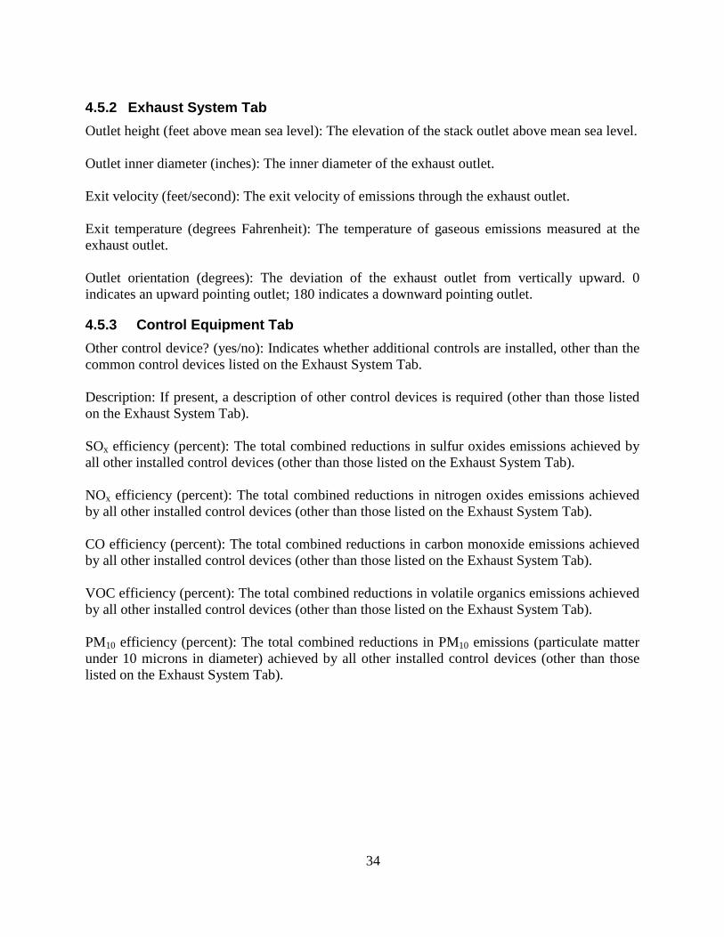
4.5.2 Exhaust System Tab Outlet height (feet above mean sea level): The elevation of the stack outlet above mean sea level. Outlet inner diameter (inches): The inner diameter of the exhaust outlet. Exit velocity (feet/second): The exit velocity of emissions through the exhaust outlet. Exit temperature (degrees Fahrenheit): The temperature of gaseous emissions measured at the exhaust outlet. Outlet orientation (degrees): The deviation of the exhaust outlet from vertically upward. 0 indicates an upward pointing outlet; 180 indicates a downward pointing outlet.
4.5.3 Control Equipment Tab Other control device? (yes/no): Indicates whether additional controls are installed, other than the common control devices listed on the Exhaust System Tab. Description: If present, a description of other control devices is required (other than those listed on the Exhaust System Tab). SOx efficiency (percent): The total combined reductions in sulfur oxides emissions achieved by all other installed control devices (other than those listed on the Exhaust System Tab). NOx efficiency (percent): The total combined reductions in nitrogen oxides emissions achieved by all other installed control devices (other than those listed on the Exhaust System Tab). CO efficiency (percent): The total combined reductions in carbon monoxide emissions achieved by all other installed control devices (other than those listed on the Exhaust System Tab). VOC efficiency (percent): The total combined reductions in volatile organics emissions achieved by all other installed control devices (other than those listed on the Exhaust System Tab). PM10 efficiency (percent): The total combined reductions in PM10 emissions (particulate matter under 10 microns in diameter) achieved by all other installed control devices (other than those listed on the Exhaust System Tab).
34

4.5.4 QC Results Tab Error Source: List of input variables for this equipment that have been flagged with QC error messages. Error Description: List of the reasons that QC error messages were assigned. Operator Comment: List of user’s explanations for unusual or unexpected values that were flagged with QC error messages. An operator comment indicates that the user wishes to override the QC error message. (To add Operator Comments, select an error message, then click “Add QC Comment”.)
35

4.6 DRILLING EQUIPMENT
4.6.1 General Information Tab Hours operated: The number of hours that a drilling rig was present and working at this structure. Total diesel fuel usage (gallons): The total diesel fuel used by the drilling rig during the survey period. Total gasoline fuel usage (gallons): The total gasoline fuel used by the drilling rig during the survey period. Total natural gas fuel usage (thousand standard cubic feet): The total natural gas used by the drilling rig during the survey period, volume adjusted to standard temperature and pressure (60 degrees Fahrenheit, 1 atmosphere). No Emissions to Report: Indicates the status of the drilling rig for the specific survey period.
• “No Emissions to Report”: Indicates that the drilling rig was absent for the entire month-long survey period.
Comments: A space for general user comments regarding this structure, with a maximum length of 255 characters.
4.6.2 Exhaust System Tab Outlet height (feet above mean sea level): The elevation of the stack outlet above mean sea level. Outlet inner diameter (inches): The inner diameter of the exhaust outlet. Exit velocity (feet/second): The exit velocity of emissions through the exhaust outlet. Exit temperature (degrees Fahrenheit): The temperature of gaseous emissions measured at the exhaust outlet. Outlet orientation (degrees): The deviation of the exhaust outlet from vertically upward. 0 indicates an upward pointing outlet; 180 indicates a downward pointing outlet.
4.6.3 Control Equipment Tab Other control device? (yes/no): Indicates whether controls are installed. Description: If present, a description of other control devices is required. SOx efficiency (percent): The total combined reductions in sulfur oxides emissions achieved by all other installed control devices.
36

NOx efficiency (percent): The total combined reductions in nitrogen oxides emissions achieved by all other installed control devices. CO efficiency (percent): The total combined reductions in carbon monoxide emissions achieved by all other installed control devices. VOC efficiency (percent): The total combined reductions in volatile organics emissions achieved by all other installed control devices. PM10 efficiency (percent): The total combined reductions in PM10 emissions (particulate matter under 10 microns in diameter) achieved by all other installed control devices.
4.6.4 QC Results Tab Error Source: List of input variables for this equipment that have been flagged with QC error messages. Error Description: List of the reasons that QC error messages were assigned. Operator Comment: List of user’s explanations for unusual or unexpected values that were flagged with QC error messages. An operator comment indicates that the user wishes to override the QC error message. (To add Operator Comment, select an error message, then click “Add QC Comment”.)
37
4.7 COMBUSTION FLARE
4.7.1 General Information Tab Note that flared emissions are combusted. If emissions are not combusted, create a Cold Vent record. Hours operated, including upsets: The total number of hours that the flare was operated during the survey period, including periods of upset flaring. Volume flared (thousand standard cubic feet), including upsets: The total volume of gas flared during the survey period, including periods of upset flaring, volume adjusted to standard temperature and pressure (60 degrees Fahrenheit, 1 atmosphere). The GOADS volume flared should match the Office of Natural Resources Revenue (ONRR)’s volume flared reported on the Oil and Gas Operations Report (OGOR). Flare gas H2S Concentration (parts per million by volume): The concentration of hydrogen sulfide present in the flare feed gas. Is there a continuous pilot? (yes/no): Indicates whether the flare stack is equipped with a continuous pilot light. Pilot fuel feed rate (thousand standard cubic feet per day): The feed rate of natural gas to a continuous pilot light. Flare combustion efficiency (percent): The flare combustion efficiency, or the completeness of hydrocarbon conversion to carbon dioxide (as CO2). Smoking condition: A qualitative assessment of the level of smoke emitted from the flare:
• None (Soot emissions are approximately 0 pounds per million British thermal units of flare gas consumed.)
• Light (Soot emissions are approximately 40 pounds per million British thermal units of flare gas consumed.)
• Medium (Soot emissions are approximately 177 pounds per million British thermal units of flare gas consumed.)
• Heavy (Soot emissions are approximately 274 pounds per million British thermal units of flare gas consumed.)
Stack outlet elevation (feet above mean sea level): The elevation of the flare stack outlet above mean sea level. Stack inner diameter (inches): The effective diameter of the flare stack at its outlet.
38

Average exit velocity (feet per second), excluding upsets: The average exit velocity of flare feed gas at the flare stack outlet during the survey period, excluding periods of upset conditions. Average combustion temperature (degrees Fahrenheit): The average flare combustion temperature during the survey period. Stack orientation (degrees): The deviation of the stack outlet from vertically upward. 0 indicates an upward pointing outlet; 180 indicates a downward pointing outlet. No Emissions to Report: Indicates the status of the flare for the specific survey period.
• “No Emissions to Report”: Indicates that the flare was unused for the entire month-long survey period.
Comments: A space for general user comments regarding this structure, with a maximum length of 255 characters.
4.7.2 QC Results Tab Error Source: List of input variables for this equipment that have been flagged with QC error messages. Error Description: List of the reasons that QC error messages were assigned. Operator Comment: List of user’s explanations for unusual or unexpected values that were flagged with QC error messages. An operator comment indicates that the user wishes to override the QC error message. (to add Operator Comments, select an error message, then click “Add QC Comment”.)
39

4.8 FUGITIVES
4.8.1 General Information Tab Stream type: Indicates the type of process stream handled by the set of components to be inventoried. (Components for different process streams at the same structure should be inventoried separately.)
• Light oil (API gravity ≥ 20°API)
• Heavy oil (API gravity<20°API)
• Oil/water mixture
• Oil/water/gas mixture
• Natural gas
• Natural gas liquids Facility Size: Indicates a rough estimate of the total count of all components at this facility that handle the selected stream type. Average VOC weight percent of fugitives: The average VOC content of fugitive emissions for the inventoried components and the selected stream type. You may find it beneficial to use the following information as a starting point.
Table 2.
Speciation Fractions for Total Hydrocarbon (THC) Emissions by Stream Type
THC Fraction Gas Light Oil (≥ 20 API Gravity)
Heavy Oil (<20 API Gravity) Water/Oil*
Methane 0.945 0.612 0.942 0.612
Volatile Organic Compounds (VOC) 0.0137 0.296 0.030 0.296
* Water/oil refers to water streams in oil service with a water content greater than 50% from the point of origin to the point where the water content reaches 99%. For water streams with a water content greater than 99%, the emission rate is considered negligible.
Average equipment elevation (feet above mean sea level): A good estimate is half the elevation of the top deck. Equipment inventory (number of components): An inventory of each type of component that handles the selected process stream at this structure. You are encouraged to prepare an equipment inventory by making direct counts of your components by service type.
40

You may find it beneficial to use of the following information as a starting point. This information was compiled for BOEM by the Offshore Operators Committee, and can be adjusted by service type for each component for each part of the production train (i.e., for each skid type). Counts must be reported for each service type (gas, heavy oil, light oil, oil/water).
Table 3.
Summary of Equipment Inventory Data (Number of Components) by Skid Type
Skid Type Val
ves
Pum
p Se
als
Thre
aded
C
onne
ctio
ns
Flan
ges
Ope
n En
ded
Line
s C
ompr
esso
r Sea
ls*
Dia
phra
gms
Dra
ins
Dum
p A
rms
Hat
ches
In
stru
men
ts
Met
ers
Pres
sure
R
elie
f V
alve
s Po
lishe
d R
ods
Oth
er R
elie
f Val
ves
Separator Skid 34 0 13 73 0 0 0 2 0 0 15 1 1 0 0 Heater Treater Skid 98 0 70 114 0 0 0 3 0 0 25 0 3 0 0 LACT Charge Pump Skid 21 3 6 47 0 0 0 1 0 0 9 0 0 0 0 LACT Skid 62 1 75 69 0 0 0 1 0 0 34 4 6 0 0 Pipeline Pumps Skid 39 3 12 78 0 0 0 2 0 0 70 0 3 0 0 Pig Launcher/Receiver Skid 13 0 14 16 0 0 0 0 0 0 9 0 1 0 0 Compressor Skid 119 0 113 138 0 4 0 1 0 0 69 0 9 4 0 Filter/Separator Skid 30 0 25 37 0 0 0 1 0 0 9 0 1 0 0 Gas Dehydration Skid 23 0 14 40 0 0 0 1 0 0 12 0 1 0 0 Glycol Regeneration Skid 134 0 110 194 0 0 0 4 0 0 45 1 7 6 1 Gas Meter 10 0 11 26 0 0 0 1 0 0 21 2 0 0 0 Fuel Gas Skid 62 0 47 85 0 0 0 1 0 0 32 1 4 0 0 Flotation Cell Skid 41 1 34 70 0 0 1 1 0 15 8 0 2 0 2 Scrubber 13 0 13 18 0 0 0 1 0 0 9 0 1 0 0 Amine Unit 226 8 166 391 0 0 1 5 0 0 121 2 12 0 1 Line Heater 30 0 46 18 0 0 0 1 0 0 10 0 0 0 1 Production Manifold 108 0 31 148 0 0 0 1 0 0 43 0 0 7 0 Wellhead 15 0 6 19 0 0 0 0 0 0 11 0 0 0 0 Import or Export Pipeline 3 0 0 9 0 0 0 0 0 0 0 0 0 0 0 * Because there is a large variation in emissions for compressor seals, you are asked to specify the
compressor and seal type:
• Centrifugal: wet seal;
• Centrifugal: dry seal;
• Reciprocating: shaft packing; or
• Other (specify).
41

Comments: A space for general user comments regarding this structure, with a maximum length of 255 characters.
4.8.2 QC Results Tab Error Source: List of input variables for this equipment that have been flagged with QC error messages. Error Description: List of the reasons that QC error messages were assigned. Operator Comment: List of user’s explanations for unusual or unexpected values that were flagged with QC error messages. An operator comment indicates that the user wishes to override the QC error message. (To add Operator Comments, select an error message, then click “Add QC Comment”.)
42

4.9 GLYCOL DEHYDRATOR UNIT
4.9.1 General Information Tab Note that the fire tube is considered to be a boiler/heater/burner. Information about the fire tube should be entered on the data entry screen for boiler/heater/burner. Access the boiler/heater/burner data entry screen by selecting Edit|New Equipment from the GOADS main menu. Select “Boiler, Heater, or Burner” as the new equipment type. Also note that recovered vapors, which are combusted elsewhere at the facility, should be accounted for by the equipment type where they are combusted. Vapors that are vented or flared locally or that are collected into the facility manifold system may be accounted for on the Ventilation System Tab. Processed throughput (million standard cubic feet): The total volume of natural gas processed by this glycol unit during the specific monthly survey period, volume adjusted to standard temperature and pressure (60 degrees Fahrenheit, 1 atmosphere). Wet gas temperature (degrees Fahrenheit): The temperature of the natural gas prior to glycol dehydration. Wet gas pressure (pounds per square inch gauge): The pressure of the natural gas prior to glycol dehydration. Equipped with a flash tank? (yes/no): Indicates whether the system is equipped with a flash tank (or separator) that vents to the atmosphere. Destination of flash gas: Indicates if the gas is routed back into the system, vented to the atmosphere, or burned in a flare. Flash tank temperature (degrees Fahrenheit): The temperature of the flash tank. Flash tank pressure (pounds per square inch gauge): The pressure of the flash tank. Uses stripping gas?: Indicates what type of stripping gas (if any) is used in the regenerator to improve water removal from the rich glycol.
• None
• Dry gas
• Flash gas: Exhaust from the flash tank
• Nitrogen: From a nitrogen supply Stripping gas flow rate (standard cubic feet per minute): The flow rate of stripping gas to the regenerator, volume adjusted to standard temperature and pressure (60 degrees Fahrenheit, 1 atmosphere).
43

No Emissions to Report: Indicates the status of the glycol dehydrator for the specific survey period.
• “No Emissions to Report”: Indicates that the equipment was unused for the entire month-long survey period.
Comments: A space for general user comments regarding this structure, with a maximum length of 255 characters.
4.9.2 Ventilation System Tab – For Still Column Vent Only Emissions destination: Indicates whether the emissions from this equipment are vented or flared locally, or at some distance from the equipment. Low-pressure vent/flare ID: Indicates the destination vent or flare identifier code (if emissions are not vented or flared locally). It may be necessary to first create a vent or flare before it will appear in the list (using the Edit|New Equipment menu). Outlet height (feet above mean sea level): The elevation of the stack outlet above mean sea level. Outlet inner diameter (inches): The inner diameter of a process vent/flare. Exit velocity (feet/second): The exit velocity of emissions through the outlet of a process vent/flare. Exit temperature (degrees Fahrenheit): The temperature of gaseous emissions measured at the outlet of a process vent. Outlet orientation (degrees): The deviation of the outlet from vertically upward. 0 indicates an upward pointing outlet; 180 indicates a downward pointing outlet. Flare feed rate (standard cubic feet per hour): The volumetric feed rate to a process flare. Combustion temperature (degrees Fahrenheit): The combustion temperature of a process flare. Combustion efficiency (percent): The combustion efficiency of a process flare, or the completeness of hydrocarbon conversion to carbon dioxide (as CO2). Installed control equipment: Indicates which common types of control devices are installed for this equipment. Condenser temperature (degrees Fahrenheit): The operating temperature of a condenser installed as a control device. Condenser pressure (absolute pounds per square inch): The operating temperature of a condenser installed as a control device.
44

4.9.3 Control Equipment Tab Other control device? (yes/no): Indicates whether additional controls are installed, other than the common control devices listed on the Ventilation System Tab. Description: If present, a description of other control devices is required (other than those listed on the Ventilation System Tab). SOx efficiency (percent): The total combined reductions in sulfur oxides emissions achieved by all other installed control devices (other than those listed on the Ventilation System Tab). NOx efficiency (percent): The total combined reductions in nitrogen oxides emissions achieved by all other installed control devices (other than those listed on the Ventilation System Tab). CO efficiency (percent): The total combined reductions in carbon monoxide emissions achieved by all other installed control devices (other than those listed on the Ventilation System Tab). VOC efficiency (percent): The total combined reductions in volatile organics emissions achieved by all other installed control devices (other than those listed on the Ventilation System Tab). PM10 efficiency (percent): The total combined reductions in PM10 emissions (particulate matter under 10 microns in diameter) achieved by all other installed control devices (other than those listed on the Ventilation System Tab).
4.9.4 QC Results Tab Error Source: List of input variables for this equipment that have been flagged with QC error messages. Error Description: List of the reasons that QC error messages were assigned. Operator Comment: List of user’s explanations for unusual or unexpected values that were flagged with QC error messages. An operator comment indicates that the user wishes to override the QC error message. (To add Operator Comments, select an error message, then click “Add QC Comment”.)
45

4.10 LOADING OPERATION
4.10.1 General Information Tab Average elevation (feet above mean sea level): The approximate elevation of loading operations, measured from mean sea level to the point of dispensing. Storage tank paint color: The exterior paint color of the dispensing storage tank. Storage tank paint condition: The exterior paint condition of the dispensing storage tank. Product Reid vapor pressure (absolute pounds per square inch): The Reid vapor pressure of the liquid contained within the dispensing storage tank. Average percent by weight of VOCs in tank vapor (percent): The VOC content of vapors in the storage tank headspace, measured as weight percent. Average molecular weight of VOCs in tank vapor (pounds per pound-mol): The average molecular weight of VOCs present in the storage tank headspace. Volume loaded (barrels): The quantity of liquid hydrocarbon loaded into ships or barges at this structure. Bulk liquid temperature (degrees Fahrenheit): The bulk temperature of the liquid contained within the dispensing storage tank. Comments: A space for general user comments regarding this structure, with a maximum length of 255 characters.
4.10.2 Ventilation System Tab Emission destination: Indicates whether the emissions from this equipment are vented or flared locally, or at some distance from the equipment. Remote vent/flare ID: Indicates the destination vent or flare identifier code (if emissions are directed through a low-pressure vent/flare manifold system). It may be necessary to first create a vent or flare before it will appear in the list (using the Edit|New Equipment menu). Outlet height (feet): The height at the outlet of a process vent/flare above the loading operation (measured from the point of dispensing to the top of the outlet). Outlet inner diameter (inches): The inner diameter of a process vent/flare. Exit velocity (feet/second): The exit velocity of emissions through the outlet of a process vent/flare. Exit temperature (degrees Fahrenheit): The temperature of gaseous emissions measured at the outlet of a process vent.
46

Outlet orientation (degrees): The deviation of the outlet from vertically upward. 0 indicates an upward pointing outlet; 180 indicates a downward pointing outlet. Flare feed rate (standard cubic feet per hour): The volumetric feed rate to a process flare. Combustion temperature (degrees Fahrenheit): The combustion temperature of a process flare. Combustion efficiency (percent): The combustion efficiency of a process flare, or the completeness of hydrocarbon conversion to carbon dioxide (as CO2). Installed control equipment: Indicates which common types of control devices are installed for this equipment. Condenser temperature (degrees Fahrenheit): The operating temperature of a condenser installed as a control device. Condenser pressure (absolute pounds per square inch): The operating temperature of a condenser installed as a control device.
4.10.3 Control Equipment Tab Other control device? (yes/no): Indicates whether additional controls are installed, other than the common control devices listed on the Ventilation System Tab. Description: If present, a description of other control devices is required (other than those listed on the Ventilation System Tab). VOC efficiency (percent): The total combined reductions in volatile organics emissions achieved by all other installed control devices (other than those listed on the Ventilation System Tab).
4.10.4 QC Results Tab Error Source: List of input variables for this equipment that have been flagged with QC error messages. Error Description: List of the reasons that QC error messages were assigned. Operator Comment: List of user’s explanations for unusual or unexpected values that were flagged with QC error messages. An operator comment indicates that the user wishes to override the QC error message. (To add Operator Comments, select an error message, then click “Add QC Comment”.)
47

4.11 LOSSES FROM FLASHING
4.11.1 General Information Tab Type of vessel: Indicates the type of vessel (separator, heater treater, surge tank, other) where the flashing occurs. API gravity of stored oil (degrees API): The API gravity of the oil/condensate contained within the vessel where the flashing occurs. Operating pressure of vessel (pounds per square inch gauge): Indicates the pressure setting of the vessel where the flashing occurs. Operating temperature of vessel (degrees Fahrenheit): Indicates the operating temperature of the vessel where the flashing occurs. Oil/condensate throughput (barrels): Indicates the actual throughput volume of oil/condensate for each vessel for the specific monthly survey period. Operating pressure immediately upstream of vessel (pounds per square inch gauge): Indicates the operating pressure upstream of the vessel. Operating temperature immediately upstream of vessel (degrees Fahrenheit): Indicates the operating temperature upstream of the vessel. Standard cubic feet of flash per barrel of oil (SCF/barrel): Indicate the SCF of flash per barrel of oil/condensate specific to your source. No Emissions to Report: Indicates the status of the vessel for the specific survey period.
• “No Emissions to Report”: Indicates that the vessel was empty and unused for the entire month-long survey period.
Comments: A space for general user comments regarding this structure, with a maximum length of 255 characters.
4.11.2 Ventilation System Tab Emissions destination: Indicates whether the emissions from this equipment are vented or flared locally, or at some distance from the equipment. Low-pressure vent/flare ID: Indicates the destination vent or flare identifier code (if emissions are not vented or flared locally). It may be necessary to first create a vent or flare before it will appear in the list (using the Edit|New Equipment menu). Outlet height (feet above mean sea level): The elevation of the stack outlet above mean sea level.
48

Outlet inner diameter (inches): The inner diameter of a process vent. Exit velocity (feet/second): The exit velocity of emissions through the outlet of a process vent. Exit temperature (degrees Fahrenheit): The temperature of gaseous emissions measured at the outlet of a process vent. Outlet orientation (degrees): The deviation of the outlet from vertically upward. 0 indicates an upward pointing outlet; 180 indicates a downward pointing outlet.
4.11.3 QC Results Tab Error Source: List of input variables for this equipment that have been flagged with QC error messages. Error Description: List of the reasons that QC error messages were assigned. Operator Comment: List of user’s explanations for unusual or unexpected values that were flagged with QC error messages. An operator comment indicates that the user wishes to override the QC error message. (To add Operator Comments, select an error message, then click “Add QC Comment”.)
49

4.12 MUD DEGASSING
4.12.1 General Information Tab Days per month of drilling with mud (i.e., drilling fluid): The total number of 24-hour days that drilling (with mud) occurred during the specific monthly survey period. Type of mud: Indicates the type of mud used (drilling fluid) (water-based, oil-based, or synthetic). No Emissions to Report: Indicates the status of the operation for the specific survey period.
• “No Emissions to Report”: Indicates that the equipment was unused for the entire month-long survey period.
Comments: A space for general user comments regarding this structure, with a maximum length of 255 characters.
4.12.2 QC Results Tab Error Source: List of input variables for this equipment that have been flagged with QC error messages. Error Description: List of the reasons that QC error messages were assigned. Operator Comment: List of user’s explanations for unusual or unexpected values that were flagged with QC error messages. An operator comment indicates that the user wishes to override the QC error message. (To add Operator Comments, select an error message, then click “Add QC Comment”.)
50

4.13 NATURAL GAS ENGINE
4.13.1 General Information Tab Hours operated: The total number of hours that this engine was in operation during the specific monthly survey period. Manufacturer: The company name of the engine manufacturer. Model No.: The manufacturer’s model number of the engine. Engine stroke: Indicates whether the engine is a 2-stroke design or a 4-stroke design. Engine burn: Indicates the fuel burn conditions (lean-burn, rich-burn, or clean-burn). Fuel H2S content (parts per million by volume): The concentration of hydrogen sulfide in gaseous fuel types. Fuel heating value (British thermal units per standard cubic feet): The energy content of gaseous fuel types. Max rated horsepower (horsepower) – The manufacturer’s maximum rated horsepower output. Operating horsepower (horsepower): The operating horsepower during operation this survey period. Max rated fuel usage (British thermal units per horsepower-hour): The manufacturer’s maximum rate of fuel usage. Average fuel usage (British thermal units per horsepower-hour): The average rate of fuel usage during operation this survey period. Total fuel used (thousand standard cubic feet): Total gaseous fuel used during this survey period, volume adjusted to standard temperature and pressure (60 degrees Fahrenheit, 1 atmosphere). If you do not monitor actual fuel use for an engine, a value may be calculated using: [Hours operated * average fuel usage (Btu/hp-hr) * operating horsepower]÷[fuel heating value (1,050 Btu/scf) * (1,000 scf/Mscf)]. No Emissions to Report: Indicates the status of the engine for the specific survey period.
• “No Emissions to Report”: Indicates that the equipment was unused for the entire month-long survey period.
Comments: A space for general user comments regarding this structure, with a maximum length of 255 characters.
51

4.13.2 Exhaust System Tab Outlet height (feet above mean sea level): The elevation of the stack outlet above mean sea level. Outlet inner diameter (inches): The inner diameter of the exhaust outlet. Exit velocity (feet/second): The exit velocity of emissions through the exhaust outlet. Exit temperature (degrees Fahrenheit): The temperature of gaseous emissions measured at the exhaust outlet. Outlet orientation (degrees): The deviation of the exhaust outlet from vertically upward. 0 indicates an upward pointing outlet; 180 indicates a downward pointing outlet.
4.13.3 Control Equipment Tab Other control device? (yes/no): Indicates whether additional controls are installed. Description: If present, a description of other control devices is required. SOx efficiency (percent): The total combined reductions in sulfur oxides emissions achieved by all other installed control devices. NOx efficiency (percent): The total combined reductions in nitrogen oxides emissions achieved by all other installed control devices. CO efficiency (percent): The total combined reductions in carbon monoxide emissions achieved by all other installed control devices. VOC efficiency (percent): The total combined reductions in volatile organic compound emissions achieved by all other installed control devices. PM10 efficiency (percent): The total combined reductions in PM10 emissions (particulate matter under 10 microns in diameter) achieved by all other installed control devices.
4.13.4 QC Results Tab Error Source: List of input variables for this equipment that have been flagged with QC error messages. Error Description: List of the reasons that QC error messages were assigned. Operator Comment: List of user’s explanations for unusual or unexpected values that were flagged with QC error messages. An operator comment indicates that the user wishes to override the QC error message. (To add Operator Comments, select an error message, then click “Add QC Comment”.)
52

4.14 NATURAL GAS, DIESEL, OR DUAL FUEL TURBINE
4.14.1 General Information Tab Manufacturer: The company name of the turbine manufacturer. Model No.: The manufacturer’s model number of the turbine. Engine purpose of use: The purpose for which this turbine is used.
• Electricity Generation
• Product Pressurization
• Other
Natural Gas Usage Operating horsepower (horsepower): The operating horsepower during operation this survey period. Average fuel usage (British thermal units per horsepower-hour): The average rate of gaseous fuel usage during operation this survey period. Fuel H2S content (parts per million by volume): The concentration of hydrogen sulfide in gaseous fuel types. Fuel heating value (British thermal units per standard cubic feet): The energy content of gaseous fuel types. Max rated horsepower (horsepower): The manufacturer’s maximum rated horsepower output. Max rated fuel usage (British thermal units per horsepower-hour): The manufacturer’s maximum rate of gaseous fuel usage. Hours operated: The total number of hours that this turbine was in operation during the specific monthly survey period. Total fuel used (thousand standard cubic feet): Total gaseous fuel used during this survey period, volume adjusted to standard temperature and pressure (60 degrees Fahrenheit, 1 atmosphere). If you do not monitor actual fuel use for a turbine, a value may be calculated using: [Hours operated * average fuel usage (Btu/hp-hr) * operating horsepower]÷[fuel heating value (1,050 Btu/scf) * (1,000 scf/Mscf)].
53

Diesel Fuel Usage Operating horsepower (horsepower): The operating horsepower during operation this survey period. Average fuel usage (British thermal units per horsepower-hour): The average rate of diesel fuel usage during operation this survey period. Fuel sulfur content (percent by mass): The sulfur content of diesel fuel. Fuel heating value (British thermal units per pound): The energy content of diesel fuel. Max rated horsepower (horsepower): The manufacturer’s maximum rated horsepower output. Max rated fuel usage (British thermal units per horsepower-hour): The manufacturer’s maximum rate of fuel usage. Hours operated: The total number of hours that this engine was in operation during the specific monthly survey period. Total fuel used (gallons): Total liquid fuel used during this survey period. If you do not monitor actual fuel use for an engine, a value may be calculated using: [Hours operated * average fuel usage (Btu/hp-hr) * operating horsepower]÷[fuel heating value (19,300 Btu/lb) * (7.05 lbs/gal)]. No Emissions to Report: Indicates the status of the turbine for the specific survey period.
• “No Emissions to Report”: Indicates that the equipment was unused for the entire month-long survey period.
Comments: A space for general user comments regarding this structure, with a maximum length of 255 characters.
4.14.2 Exhaust System Tab Outlet height (feet above mean sea level): The elevation of the stack outlet above mean sea level. Outlet inner diameter (inches): The inner diameter of the exhaust outlet. Exit velocity (feet/second): The exit velocity of emissions through the exhaust outlet. Exit temperature (degrees Fahrenheit): The temperature of gaseous emissions measured at the exhaust outlet. Outlet orientation (degrees): The deviation of the exhaust outlet from vertically upward. 0 indicates an upward pointing outlet; 180 indicates a downward pointing outlet.
54

4.14.3 Control Equipment Tab Other control device? (yes/no): Indicates whether additional controls are installed, other than the common control devices listed on the Exhaust System Tab. Description: If present, a description of other control devices is required (other than those listed on the Exhaust System Tab). SOx efficiency (percent): The total combined reductions in sulfur oxides emissions achieved by all other installed control devices (other than those listed on the Exhaust System Tab). NOx efficiency (percent): The total combined reductions in nitrogen oxides emissions achieved by all other installed control devices (other than those listed on the Exhaust System Tab). CO efficiency (percent): The total combined reductions in carbon monoxide emissions achieved by all other installed control devices (other than those listed on the Exhaust System Tab). VOC efficiency (percent): The total combined reductions in volatile organics emissions achieved by all other installed control devices (other than those listed on the Exhaust System Tab). PM10 efficiency (percent): The total combined reductions in PM10 emissions (particulate matter under 10 microns in diameter) achieved by all other installed control devices (other than those listed on the Exhaust System Tab).
4.14.4 QC Results Tab Error Source: List of input variables for this equipment that have been flagged with QC error messages. Error Description: List of the reasons that QC error messages were assigned. Operator Comment: List of user’s explanations for unusual or unexpected values that were flagged with QC error messages. An operator comment indicates that the user wishes to override the QC error message. (To add Operator Comments, select an error message, then click “Add QC Comment”.)
55
4.15 PNEUMATIC PUMPS
4.15.1 General Information Tab Manufacturer: The company name of the equipment manufacturer. Examples include: Wilden diaphragm pumps (M-1, M-2, M-4, M-8, M-15); and Texsteam chemical injection and diaphragm pumps. Model: The manufacturer’s model number of the pump. Only include pumps that are in natural gas service. Do not include pumps in compressed air service. Fuel usage rate (standard cubic feet per hour): The rate of natural gas usage during operation this survey period. If this information is not readily available, it is not mandatory that you enter this data. Hours operated: The total number of hours that the pump was in operation during the specific monthly survey period. No Emissions to Report: Indicates the status of the pump for the specific survey period.
• “No Emissions to Report” – Indicates that the pump was unused for the entire month-long survey period.
Comments: A space for general user comments regarding this structure, with a maximum length of 255 characters.
4.15.2 Ventilation System Tab Emissions destination: Indicates whether the emissions from this equipment are vented or flared locally, or at some distance from the equipment. Low-pressure vent/flare ID: Indicates the destination vent or flare identifier code (if emissions are not vented or flared locally). It may be necessary to first create. Outlet height (feet above mean sea level): The elevation of the stack outlet above mean sea level. Outlet inner diameter (inches): The inner diameter of a process vent. Exit velocity (feet/second): The exit velocity of emissions through the outlet of a process vent. Exit temperature (degrees Fahrenheit): The temperature of gaseous emissions measured at the outlet of a process vent. Outlet orientation (degrees): The deviation of the outlet from vertically upward. 0 indicates an upward pointing outlet; 180 indicates a downward pointing outlet.
4.15.3 QC Results Tab Error Source: List of input variables for this equipment that have been flagged with QC error messages.
56

Error Description: List of the reasons that QC error messages were assigned. Operator Comment: List of user’s explanations for unusual or unexpected values that were flagged with QC error messages. An operator comment indicates that the user wishes to override the QC error message. (To add Operator Comments, select an error message, then click “Add QC Comment”.)
57

4.16 PRESSURE/LEVEL CONTROLLERS
4.16.1 General Information Tab Service Type: Indicates whether the equipment is in pressure control or level control service. Manufacturer: The company name of the equipment manufacturer. Only include equipment that is in natural gas service. Do not include equipment in compressed air service. Model: The manufacturer’s model number of the equipment. Number of this make-model: Number of equipment of this exact make and model. Fuel usage rate (standard cubic feet per hour): The rate of natural gas usage during operation this survey period. If this information is not readily available, it is not mandatory that you enter this data. Hours operated: The total number of hours that the equipment was in operation during the specific monthly survey period. Equipment elevation (feet above mean sea level): A good estimate is half the elevation of the top deck. No Emissions to Report: Indicates the status of the equipment operations for the specific survey period.
• “No Emissions to Report”: Indicates that the equipment was unused for the entire month-long survey period.
Comments: A space for general user comments regarding this structure, with a maximum length of 255 characters.
4.16.2 QC Results Tab Error Source: List of input variables for this equipment that have been flagged with QC error messages. Error Description: List of the reasons that QC error messages were assigned. Operator Comment: List of user’s explanations for unusual or unexpected values that were flagged with QC error messages. An operator comment indicates that the user wishes to override the QC error message. (To add Operator Comments, select an error message, then click “Add QC Comment”.)
58
4.17 STORAGE TANK
4.17.1 General Information Tab Product throughput (barrels): The volume of liquid hydrocarbon turned over through the storage tank during the survey period. Tank orientation (horizontal/vertical): Indicates whether the tank is elongated and narrow in the horizontal direction (horizontal), or otherwise (vertical). Tank shape (cylindrical/rectangular): Indicates whether the tank is cylindrical or rectangular in shape. Average liquid height (feet): The average height of stored liquid during the survey period, measured from the bottom of the storage space to the top of the liquid. Tank shell diameter (feet): The diameter of a cylindrical tank (either horizontal or vertical). Tank shell height (feet): The vertical height of a cylindrical tank (oriented vertically) or of a rectangular tank (oriented vertically or horizontally). Tank shell length (feet): The longest horizontal dimension of a horizontal tank. Tank shell width (feet): The horizontal width of a rectangular tank (oriented vertically or horizontally). 2nd Tank shell width (feet): The 2nd horizontal width of a rectangular tank (oriented vertically). Is the roof fixed (not floating)? (yes/no): Indicates whether the tank has a fixed or floating roof. Roof shape: Indicates the shape of a vertical tank’s roof.
• Cone: cylindrical tanks
• Dome: cylindrical tanks
• Flat: cylindrical or rectangular
• Peaked: rectangular
Roof height above shell (feet): The height of a fixed roof measured from the top of the tank shell to the highest point of the roof. Breather vent pressure setting (pounds per square inch gauge): The pressure setting of the tank breather valve. Breather vent vacuum setting (pounds per square inch gauge): The vacuum setting of the tank breather valve.
59

Paint color: The exterior paint color of the storage tank. Paint condition: The exterior paint condition of the storage tank. Bulk liquid temperature (degrees Fahrenheit): The bulk temperature of the liquid contained within the storage tank. Product type (crude/condensate): Indicates whether the storage tank contains crude oil or condensates. It is not mandatory that you enter data for jet fuel storage tanks. API gravity (degrees API): The API gravity of the liquid contained within the storage tank. Product Reid vapor pressure (absolute pounds per square inch): The Reid vapor pressure of the liquid contained within the storage tank. Average percent by weight of VOCs in tank vapor (percent): The VOC content of vapors in the storage tank headspace, measured as weight percent. Average molecular weight of VOCs in tank vapor (pounds per pound-mol): The average molecular weight of VOCs present in the storage tank headspace. Equipped with a flash tank? (yes/no): Indicates whether the storage tank is equipped with an upstream flash tank. No Emissions to Report: Indicates the status of the storage for the specific survey period.
• “No Emissions to Report”: Indicates that the tank was empty and unused for the entire month-long survey period.
Comments: A space for general user comments regarding this structure, with a maximum length of 255 characters.
4.17.2 Ventilation System Tab Emissions destination: Indicates whether the emissions from this equipment are vented or flared locally, or at some distance from the equipment. Low-pressure vent/flare ID: Indicates the destination vent or flare identifier code (if emissions are not vented or flared locally). It may be necessary to first create. Outlet height (feet above mean sea level): The elevation of the stack outlet above mean sea level. Outlet inner diameter (inches): The inner diameter of a process vent or the effective diameter of a flare. Exit velocity (feet/second): The exit velocity of emissions through the outlet of a process vent/flare.
60

Exit temperature (degrees Fahrenheit): The temperature of gaseous emissions measured at the outlet of a process vent. Outlet orientation (degrees): The deviation of the outlet from vertically upward. 0 indicates an upward pointing outlet; 180 indicates a downward pointing outlet. Flare feed rate (standard cubic feet per hour): The volumetric feed rate to a process flare. Combustion temperature (degrees Fahrenheit): The combustion temperature of a process flare. Combustion efficiency (percent): The combustion efficiency of a process flare, or the completeness of hydrocarbon conversion to carbon dioxide (as CO2). Installed control equipment: Indicates which common types of control devices are installed for this equipment. Condenser temperature (degrees Fahrenheit): The operating temperature of a condenser installed as a control device. Condenser pressure (absolute pounds per square inch): The operating pressure of a condenser installed as a control device.
4.17.3 Control Equipment Tab Other control device? (yes/no): Indicates whether additional controls are installed, other than the common control devices listed on the Ventilation System Tab. Description: If present, a description of other control devices is required (other than those listed on the Ventilation System Tab). VOC efficiency (percent): The total combined reductions in volatile organics emissions achieved by all other installed control devices (other than those listed on the Ventilation System Tab).
4.17.4 QC Results Tab Error Source: List of input variables for this equipment that have been flagged with QC error messages. Error Description: List of the reasons that QC error messages were assigned. Operator Comment: List of user’s explanations for unusual or unexpected values that were flagged with QC error messages. An operator comment indicates that the user wishes to override the QC error message. (To add Operator Comments, select an error message, then click “Add QC Comment”.)
61

4.18 COLD VENT
4.18.1 General Information Tab Note that vented emissions are NOT combusted. If emissions are combusted, create a Combustion Flare record. Hours operated, including upsets – The total number of hours that the vent was operated during the survey period, including periods of upset venting. Volume vented (thousand standard cubic feet), including upsets: The total volume of gas vented during the survey period, including periods of upset venting, volume adjusted to standard temperature and pressure (60 degrees Fahrenheit, 1 atmosphere). The GOADS volume vented should match the Office of Natural Resources Revenue (ONRR)’s volume vented reported on the Oil and Gas Operations Report (OGOR). Vent type: Indicates whether vent gases are released at high pressure or low pressure. Vent gas H2S Concentration (parts per million by volume): The concentration of hydrogen sulfide present in the vented gas. Vent gas VOC Concentration (parts per million by volume): The concentration of volatile organic compounds present in the vented gas. Average molecular weight of VOCs (lb/lb-mol): The average molecular weight of VOCs present in the vented gas. Stack outlet elevation (feet above mean sea level): The elevation of the vent stack outlet above mean sea level. Stack inner diameter (inches): The inner diameter of the vent stack at its outlet. Average exit velocity (feet per second): The average exit velocity of vented gas at the stack outlet. Exit temperature (degrees Fahrenheit): The average temperature of vented gas at the stack outlet. Stack orientation (degrees): The deviation of the stack outlet from vertically upward. 0 indicates an upward pointing outlet; 180 indicates a downward pointing outlet. Installed control equipment: Indicates which common types of control devices are installed on the vent. Condenser temperature (degrees Fahrenheit): The operating temperature of a condenser installed as a control device.
62

Condenser pressure (absolute pounds per square inch): The operating pressure of a condenser installed as a control device. No Emissions to Report: Indicates the status of the vent for the specific survey period.
• “No Emissions to Report”: Indicates that the vent was unused for the entire month-long survey period.
Comments: A space for general user comments regarding this structure, with a maximum length of 255 characters.
4.18.2 Control Equipment Tab Other control device? (yes/no): Indicates whether controls are installed. Description: If present, a description of other control devices is required. VOC efficiency (percent): The total combined reductions in volatile organics emissions achieved by all other installed control devices.
4.18.3 QC Results Tab Error Source: List of input variables for this equipment that have been flagged with QC error messages. Error Description: List of the reasons that QC error messages were assigned. Operator Comment: List of user’s explanations for unusual or unexpected values that were flagged with QC error messages. An operator comment indicates that the user wishes to override the QC error message. (To add Operator Comments, select an error message, then click “Add QC Comment”.)
63


5. GOADS-2014 QA SUMMARY FORM DATA FIELDS This section indicates the data fields that will be flagged in the QA Summary Form if they are missing or inconsistent from month to month. If all of your GOADS-2014 entries are complete and the values are within two standard deviations of the average for all values in that field, the QA Summary Form will be blank. The data fields in the QA Summary Form are critical to developing emission estimates. If an element appears on the QA Summary Form printout, you should re-evaluate your GOADS-2014 file and complete or correct the data you entered for the equipment or month shown. If the flagged value is legitimate, you may annotate the QA Summary Form using colored ink, or attach additional sheets which specify why a value is valid and does not need to be changed. You must export the GOADS-2014 QA Summary Form and submit it with your data files. If any values are flagged as incomplete or inconsistent, BOEM may contact you. Please make sure you review the QA Summary Form closely, correct and errors that are flagged, and provide separate documentation to note that flagged entries that are valid. The following table lists the type codes used on the QA Summary Form.
65

Table 4.
GOADS-2014 QA Summary Form Equipment Type Codes
AMI Amine gas sweetening unit BOI Boiler/heater/burner DIE Diesel or gasoline engine DRI Drilling rig FLA Combustion flare FUG Fugitives GLY Glycol dehydrator unit LOA Loading operation LOS Losses from flashing MUD Mud degassing NGE Natural gas engine NGT Natural gas, diesel, and dual-fuel turbine PNE Pneumatic pumps PRE Pressure/level controllers STO Storage tank VEN Cold vent
66

Table 5.
GOADS-2014 QA Summary Form Data Fields
General Operator Information
User name and phone number
Company name
Survey Information
12 surveys included
Structure Information
Area/Block/Name
Longitude/latitude
Distance to shore
Gas production
Crude oil production
Natural gas usage for all 12 months consistent with survey data
Diesel fuel usage for all 12 months consistent with survey data
Gasoline usage for all 12 months consistent with survey data
Number and unique pieces of equipment consistent for all 12 mos.
Sales gas composition
67

Table 5.
GOADS-2014 QA Summary Form Data Fields (continued)
Equipment Information
Amine Gas Sweetening Unit
Processed throughput
Hours operated
Unprocessed natural gas concentration (% by volume)
Amine type
Equipped with a flash tank (yes/no)
Disposition of flash gas
Vented into low-pressure system
Gases vented or flared
Boiler/heater/burner
Fuel type
Maximum rated heat input
Hours of operated
Average heat input
Same equipment units reported for each month/survey
Diesel or Gasoline Engine
Fuel type
Maximum rated horsepower
Hours operated
Operating horsepower
Maximum rated fuel usage
Average fuel usage
Same equipment units reported for each month/survey
Drilling Rig
Hours operated
Total diesel fuel usage
Total gasoline usage
Total natural gas fuel usage
68

Table 5.
GOADS-2014 QA Summary Form Data Fields (continued)
Equipment Information
Combustion Flare
Volume flared reported for continuous and episodic flaring
Continuous pilot
Pilot fuel feed rate
Fugitives
Stream type (gas, heavy oil, light oil, or water/oil)
Average VOC weight %
Number of components that handle the stream type
Glycol Dehydrator Unit
Processed throughput
Equipped with a flash tank (yes/no)
Disposition of flash gas
Loading Operation
Volume loaded to ships and barges
Tank color
Tank condition
Losses from Flashing
Type of vessel
API gravity of stored oil
Operating pressure of each vessel
Operating temperature of each vessel
Operating pressure upstream of vessel
Operating temperature upstream of vessel
Oil/condensate throughput for each vessel
Disposition of flash gas
Mud Degassing
Number of drilling days (with mud)
Mud type used (water-based, synthetic, oil-based)
69

Table 5.
GOADS-2014 QA Summary Form Data Fields (continued)
Equipment Information
Natural Gas Engine
Engine stroke
Engine burn
Hours operated
Operating horsepower
Maximum rated fuel usage
Average fuel usage
Same equipment units reported for each month/survey
Natural Gas, Diesel, or Dual-Fuel Turbine
Hours operated
Operating horsepower
Maximum rated fuel usage
Average fuel usage
Same equipment units reported for each month/survey
Pneumatic Pumps
Manufacturer
Model
Hours operated
Pressure/level Controllers
Manufacturer
Model
Hours operated
Service type
70

Table 5.
GOADS-2014 QA Summary Form Data Fields (continued)
Equipment Information
Storage Tank
Product throughput
Product type
Tank color
Tank condition
Tank shape
Tank orientation
Tank shell height
Tank shell diameter
Tank shell width
Roof shape
Roof height above shell
Equipped with a flash tank (yes/no)
Cold Vent
Hours operated, including upsets
Volume vented, including upsets
Control device identified
Average vent feed
71

The Department of the Interior Mission
As the Nation’s principal conservation agency, the Department of the Interior has responsibility for most of our nationally owned public lands and natural resources. This includes fostering the sound use of our land and water resources; protecting our fish, wildlife, and biological diversity; preserving the environmental and cultural values of our national parks and historical places; and providing for the enjoyment of life through outdoor recreation. The Department assesses our energy and mineral resources and works to ensure that their development is in the best interests of all our people by encouraging stewardship and citizen participation in their care. The Department also has a major responsibility for American Indian reservation communities and for people who live in island communities. The Bureau of Ocean Energy Management Mission The Bureau of Ocean Energy Management (BOEM) works to manage the exploration and development of the nation's offshore resources in a way that appropriately balances economic development, energy independence, and environmental protection through oil and gas leases, renewable energy development and environmental reviews and studies.