Embed Size (px)
Citation preview

USER’S GUIDEFOR8210
BUBBLERWATER LEVEL
GAUGEFOR
HYDROGRAPHIC SURVEYING
APPLICATIONS(Installation and Operation)
Prepared byPacific Regional Office of
Field Operations Division andRequirements and Development Division
ofCenter for Operational Oceanographic
Products and ServicesNational Ocean Service
National Oceanic and AtmosphericAdministration
February 2001

TABLE OF CONTENTS
BACKGROUND INFORMATION AND GENERAL DESCRIPTION . . . . . . . . . . . . . . . Page 1
INTRODUCTION TO THE 8210 HYDRO GAUGE . . . . . . . . . . . . . . . . . . . . . . . . . . . . . Page 2Main Parts . . . . . . . . . . . . . . . . . . . . . . . . . . . . . . . . . . . . . . . . . . . . . . . . . . . . . . . . Page 2Fuses . . . . . . . . . . . . . . . . . . . . . . . . . . . . . . . . . . . . . . . . . . . . . . . . . . . . . . . . . . . . Page 2Outer Case . . . . . . . . . . . . . . . . . . . . . . . . . . . . . . . . . . . . . . . . . . . . . . . . . . . . . . . . Page 38210 Water Level Gauge Side View . . . . . . . . . . . . . . . . . . . . . . . . . . . . . . . . . . . . Page 4The Pressure Control Panel . . . . . . . . . . . . . . . . . . . . . . . . . . . . . . . . . . . . . . . . . . . Page 5Valves . . . . . . . . . . . . . . . . . . . . . . . . . . . . . . . . . . . . . . . . . . . . . . . . . . . . . . . . . . . Page 5Flow Meter . . . . . . . . . . . . . . . . . . . . . . . . . . . . . . . . . . . . . . . . . . . . . . . . . . . . . . . . Page 5Differential Flow Controller . . . . . . . . . . . . . . . . . . . . . . . . . . . . . . . . . . . . . . . . . . Page 6Directional Filter . . . . . . . . . . . . . . . . . . . . . . . . . . . . . . . . . . . . . . . . . . . . . . . . . . . Page 6System Tie-Down . . . . . . . . . . . . . . . . . . . . . . . . . . . . . . . . . . . . . . . . . . . . . . . . . . Page 6Electrical and Pressure Connections . . . . . . . . . . . . . . . . . . . . . . . . . . . . . . . . . . . . Page 6Wiring and Connections . . . . . . . . . . . . . . . . . . . . . . . . . . . . . . . . . . . . . . . . . . . . . Page 7GOES Radio Transmitter . . . . . . . . . . . . . . . . . . . . . . . . . . . . . . . . . . . . . . . . . . . . . Page 8Nitrogen supply . . . . . . . . . . . . . . . . . . . . . . . . . . . . . . . . . . . . . . . . . . . . . . . . . . . . Page 9Orifice connection . . . . . . . . . . . . . . . . . . . . . . . . . . . . . . . . . . . . . . . . . . . . . . . . . . Page 9Laptop connection . . . . . . . . . . . . . . . . . . . . . . . . . . . . . . . . . . . . . . . . . . . . . . . . . . Page 9Batteries . . . . . . . . . . . . . . . . . . . . . . . . . . . . . . . . . . . . . . . . . . . . . . . . . . . . . . . . . Page 10
START-UP . . . . . . . . . . . . . . . . . . . . . . . . . . . . . . . . . . . . . . . . . . . . . . . . . . . . . . . . . . . . Page 11Sutron 8210 Data Collection Platform . . . . . . . . . . . . . . . . . . . . . . . . . . . . . . . . . . Page 11Bubbler Control Unit . . . . . . . . . . . . . . . . . . . . . . . . . . . . . . . . . . . . . . . . . . . . . . . Page 118210 Gauge GOES Capability . . . . . . . . . . . . . . . . . . . . . . . . . . . . . . . . . . . . . . . . Page 13
SITE VISITS . . . . . . . . . . . . . . . . . . . . . . . . . . . . . . . . . . . . . . . . . . . . . . . . . . . . . . . . . . . Page 14Staff Observations . . . . . . . . . . . . . . . . . . . . . . . . . . . . . . . . . . . . . . . . . . . . . . . . . Page 14Battery Check . . . . . . . . . . . . . . . . . . . . . . . . . . . . . . . . . . . . . . . . . . . . . . . . . . . . . Page 14Data Retrieval . . . . . . . . . . . . . . . . . . . . . . . . . . . . . . . . . . . . . . . . . . . . . . . . . . . . Page 14
Data Retrieval - Direct Connection . . . . . . . . . . . . . . . . . . . . . . . . . . . . . . Page 14Data Display - Direct Connection . . . . . . . . . . . . . . . . . . . . . . . . . . . . . . . . . . . . . Page 15Sutron-Authored Programs . . . . . . . . . . . . . . . . . . . . . . . . . . . . . . . . . . . . . . . . . . Page 16PCMCIA Card Reader . . . . . . . . . . . . . . . . . . . . . . . . . . . . . . . . . . . . . . . . . . . . . . Page 17Downloading Data to a PCMCIA (Ram) Card . . . . . . . . . . . . . . . . . . . . . . . . . . . Page 17
To Download . . . . . . . . . . . . . . . . . . . . . . . . . . . . . . . . . . . . . . . . . . . . . . . Page 18To View Data . . . . . . . . . . . . . . . . . . . . . . . . . . . . . . . . . . . . . . . . . . . . . . . Page 18
8210 MENUS . . . . . . . . . . . . . . . . . . . . . . . . . . . . . . . . . . . . . . . . . . . . . . . . . . . . . . . . . . . Page 19Configure Sensors . . . . . . . . . . . . . . . . . . . . . . . . . . . . . . . . . . . . . . . . . . . . . . . . . Page 21

APPENDIX A GUIDELINES FOR OPERATION AND DOCUMENTATION OF HYDRO GAGESWITH GOES CAPABILITY . . . . . . . . . . . . . . . . . . . . . . . . . . . . . . . . . . . . . . . . . . . . . A1Transmitting data using GOES . . . . . . . . . . . . . . . . . . . . . . . . . . . . . . . . . . . . . . . . . . . A1
1. Assignment of platform IDs and station numbers for tide station installations:. . . . . . . . . . . . . . . . . . . . . . . . . . . . . . . . . . . . . . . . . . . . . . . . . . . . . . . . A1
2. Record and documentation requirements . . . . . . . . . . . . . . . . . . . . . . . . . . . . A13. Removal of tide stations and reinstallation of gauges . . . . . . . . . . . . . . . . . . A2
APPENDIX B8210 SOFTWARE NAVIGATION . . . . . . . . . . . . . . . . . . . . . . . . . . . . . . . . . . . . . . . B1SYSTEM SETUP . . . . . . . . . . . . . . . . . . . . . . . . . . . . . . . . . . . . . . . . . . . . . . . . . . . . . B2
APPENDIX CPROBLEMS WITH EQUIPMENT OR STATIONS DATA . . . . . . . . . . . . . . . . . . . . C1
APPENDIX DTROUBLESHOOTING GUIDE . . . . . . . . . . . . . . . . . . . . . . . . . . . . . . . . . . . . . . . . . . D1
APPENDIX EPNEUMATIC CONNECTIONS . . . . . . . . . . . . . . . . . . . . . . . . . . . . . . . . . . . . . . . . . . E1
APPENDIX FCHANGING THE NITROGEN TANK . . . . . . . . . . . . . . . . . . . . . . . . . . . . . . . . . . . . F1
APPENDIX GGAUGE PRESSURE PARAMETERS . . . . . . . . . . . . . . . . . . . . . . . . . . . . . . . . . . . . . G1
APPENDIX HSWAGELOK INFORMATION . . . . . . . . . . . . . . . . . . . . . . . . . . . . . . . . . . . . . . . . . . H1

8210 Bubbler User’s Guide February 2001Page 1
Figure 1: 8210 Hydrographic Water Level Gauge
BACKGROUND INFORMATION AND GENERAL DESCRIPTION
The 8210 Hydrographic Water Level Gauge was developed to replace the 8200 DigitalWater Level Gauge. The new gauge consists of a Sutron 8210 Data Collection Platform (DCP)with a GOES transmitter and a built-in pressure manifold and flow meter assembly and is incasedin a Pelican model 1200 equipment case. The new gauge is designed to allow the lid to beopened in an inclement weather without endangering the electronics inside the case. The 8210 isequipped with a GOES radio transmitter to transmit tidal data to NOS headquarters at SilverSpring, Maryland, via GOES satellite through the National Environmental Satellite and DataInformation Service (NESDIS) facility at Wallops Island, for quality control and analyses.
The development of the 8210 hydrographic water level gauge is a continuingimprovement process of development of Sutron 8200 gauges which were used in the past for thehydrographic survey applications, and cooperative efforts from the Requirements andDevelopment Division (RDD) at Silver Spring, Maryland, the Pacific Regional Office (PRO) atSeattle, Washington, of the Field Operations Division (FOD), both of the Center for OperationalOceanographic Products and Services (CO-OPS), the NOAA Ship Rainier, and the SutronCorporation. Close interaction among all parties involved has resulted in measurement systemmodifications by taking into account suggestions and comments from the field user, andmaintaining the measurement performance and system compatibility required for data analysis.

8210 Bubbler User’s Guide February 2001Page 2
The hydro gauge measures tides utilizing back pressure from a bubblier orifice installedjust below the lowest observed water level. The back pressure is measured using a ParoScientificPressure Sensor (PAROS). The pressure and feed are controlled with a constant differential flowcontroller. The flow rate is adjusted using a flow control needle valve and a flow meter. Gasconnections to and from the tide gauge utilize quick connect snap lock fittings that close whenthe connection is removed. This keeps a positive pressure inside the manifold assembly at alltimes.
The Pelican case lid is vented through a small hole drilled through the lid. This allowsthe PAROS sensor to compensate for changes in barometric pressure outside the case. The lowercompartment uses a bidirectional purge valve that will open when there is a pressure change ofone psi or more either inside or outside the case. This will protect the gauge from exploding inthe event of a gas leak in the lower compartment and will depressurize the case when transportedby aircraft.
General procedures on system installation and operation are summarized in thisdocument. Each gauge enclosure contains a few pages of brief operating instructionssummarized from this manual which provide information regarding setup parameters for theSutron 8210 DCP, a log sheet for recording field visits, operational problems and/or servicessuch as battery replacement, etc.
INTRODUCTION TO THE 8210 HYDRO GAUGE
Main Parts
The hydro gauge components are mounted on three panel sections. The 8210 mainsection contains the 8210 electronics board and the GOES transmitter. The interconnect sectioncontains the interconnect board, the RS-232 connector, and the two waterproof fuse holders. The gas purging section holds the PAROS pressure sensor, a net envelope used for holdingdehumidification packets, and the plumbing for the gas purging system.
Fuses
There are two AGC 6 amp fuses on the front panel of the tide gauge. One is connected tothe battery line, and the other is connected to the solar panel. The 8210 electronics panel has twoadditional fuses, one is in a fuse holder which provides power to the GOES radio transmitter, andthe other is on the interconnect board.

8210 Bubbler User’s Guide February 2001Page 3
Figure 2: Front Panel of 8210 Hydro Gauge
Outer Case
The case is an O-ring sealed, water resistant, durable plastic case. Though it is notdesigned to do so, it will float if dropped overboard. The power connector is a four-pin waterresistant connector which connects to the battery boxes. The 8210 gauge uses two 12-volt 26Amp Hr batteries. The batteries are connected in parallel with a four-conductor 5-foot cable. Each battery box has two connectors wired in parallel, either will provide power to the 8210. The remaining connector is used to daisy-chain the batteries together and on the last battery caseconnect to the 20-watt solar panel using a 20-foot four-conductor cable. The solar power when asolar panel is utilized, provides power to the 8210 gauge. The Antenna connector is a type “N”female connector. All of the connectors have protective caps. This cap should cover theconnectors whenever the connectors are not used.
Changing the Display Brightness:The brightness of the display can be changed by pressing the“SET” button when the message Sutron 8210 GS49 isdisplayed The best time to do this is immediately after turningthe display on. Each time “SET” is pressed the brightness willchange.

8210 Bubbler User’s Guide February 2001Page 4
Figure 4: Batteries and Connections
Figure 3: Side view of the 8210 gauge
Battery Connector MS3106E14s-2sPins Wire Color TerminationA-------------------Red----------- Battery +D-------------------Black---------Battery -B-------------------White---------Solar Panel +C-------------------Green---------Solar Panel -
8210 Water Level Gauge Side View

8210 Bubbler User’s Guide February 2001Page 5
Figure 5: Front of Pressure Control Panel
Figure 6: Back View of Pressure Control Unit
The Pressure Control Panel
There are four valves on thePressure Control Panel, viz theinlet valve, the bypass valve, outletvalve, and the flow control valve. In addition to the valves there isalso a vent port and a flow meter.
On the back side of the PressureControl Panel is the MooreDifferential Flow Controller, thePAROS Pressure Sensor,Directional Filter, and QuickDisconnect Fittings which allowseasy removal of the panel.
Valves
• The inlet valve is used to open and close the gas flow to the orifice. It is normally openand would be closed when changing the nitrogen cylinder.
• The bypass valve is used to shunt around the manifold assembly. This valve is used toquickly purge the water out of the bubbler tube and must be closed during data collection.
• The Flow control valve is used to control the gas flow rate. The greater the tidal range,the larger the required flow. The 8210 tide gauge must be in the upright position to setthe flow rate. Once the flow rate is set with it’s needle valve, the gauge can be positionedat any angle.
Flow Meter
The 8210 gauge uses a Cole Parmer 0-51 ml/min flow meter to set the flow rate. Thescale on the glass tube is simply the length of the tube and does not relate to milliliters. However, all values stated in this manual will refer to the numbers printed on the glass tube.

8210 Bubbler User’s Guide February 2001Page 6
Differential Flow Controller
The Moore constant differential flow controller maintains a constant gas flow rate over acontinually adjustable flow range as set by the flow control valve.
Directional Filter
The directional filter is used to prevent back flow, in the event that the nitrogen gas line is cut orremoved from the gas regulator. This will allow the tide gauge to continue to operate for severalhours without loss of data, or till the gauge can be fixed, if applicable.
System Tie-Down
The 8210 water level tide gauge can be operated laying flat on its back. The only timethis gauge needs to be in an upright position is to set the flow rate as stated above. Severalattachment points are available on the bubbler system enclosure for tie-downs at the field site. Metal brackets are provided with each system which can be bolted to each corner on the rear ofthe enclosure. A carrying handle is located at the right side of the enclosure. Looping cablethrough this handle on the side would provide a tie-down point for the enclosure. Locks shouldbe used to secure the gauge and can also be used for tide down points.
Electrical and Pressure Connections
All external connections are located near the handle of the enclosure. Connection of thetide gauge to the nitrogen supply and to the orifice line during deployment requires the use ofSwagelok® quick disconnect fittings. The orifice fitting uses a red male fitting with a stainlesssteel Swagelok® tube fitting on the other end. A 3/4 and 11/16-inch wrench is required totighten this fitting. Nitrogen supply hose is provided with a female quick disconnect fittingattached to it.
Caution: Excessive torque in making these connections must be avoided. See Appendix Hinstructions and drawing of Swagelok® fittings.
Note the difference between new installation (one and one-quarter turns past finger tight for 1/4-inch and larger tubing sizes) and re-tightening (only one-quarter turn past finger tight).
Caution: Tightening beyond these points will damage the mating surfaces, and result in a gasleak.
The polyethylene orifice tubing could be extended or repaired by joining two pieces usinga Swagelok® Splice fitting. In order to avoid leaks, be sure that the tubing ends are cut squareand smooth, and the tubing is free from scratches in the area that will be inserted into the fitting.

8210 Bubbler User’s Guide February 2001Page 7
Figure 8: Interconnect and CPU Board
Figure 7: Interconnect board
Wiring and Connections
SDI-12 to D9 pin ConnectorPin Wire Color D9 Connector Female5--------------------------Yellow-----------------------------5 Signal and Power Ground6--------------------------White-------------------------------9 Power 6 to 16 VDC @15ma7--------------------------Brown------------------------------2 SDI-12 Data
RS-232 --------------ITT Cannon MS3112E-10-6S-----------------Wire ColorA--------------------Not used
2-----------------------B---------------------TXD-------------------------Red3-----------------------C---------------------RXD------------------------Green4-----------------------D---------------------DSR-------------------------Blue

8210 Bubbler User’s Guide February 2001Page 8
Figure 9: GOES Transmitter and CPU Board
Figure 10: GOES transmitter
GOES Radio Transmitter
GOES Radio Fail-safeThe fail-safe circuitry is designed to prevent transmitters fromjamming a channel. The fail-safe limits both the length oftransmissions and the time between consecutive transmissions.The fail-safe circuit is normally reset from either the frontpanel, a laptop computer, or by the push-buttons on the frontpanel of the 8210. To reset the fail-safe from the front panelor PC, you must go to the Main Menu\Recording field. If thisfield includes “FT” the fail-safe is tripped. To reset the fail-safe condition, press “SET” or “R” in the PC menu severaltimes until the “FT” is deleted. Normally what you will see onthe display is recording status “OFF&FT” and it will toggle to“OFF”. Typically you will not have to reset the transmitterwith the reset switch in the GOES transmitter board.

8210 Bubbler User’s Guide February 2001Page 9
Nitrogen supply
The nitrogen supply connection uses a 1/4-inch stainless steel Swagelok® quickdisconnect fitting. If the new gas supply hose (Swagelok® fittings on both ends) is used,it will require installation of a female quick disconnect fitting and a hose-to-pipe fitting tothe nitrogen regulator. No other hose or fitting should be used.
Orifice connection
The orifice connection is a 1/4-inch stainless steel quick disconnect Swagelok®fitting to a 3/8-inch tube to tube fitting using about 12 inch section of bubbler tubingwhich forms a pigtail. This provides a sacrificial piece of tubing that can be terminatedmany times if the 3/8-inch connector is damaged or needs to be replaced, without havingto replace the more expensive quick disconnect fitting. If connection of the orifice tubingis a new installation, it will require swaging a new ferrule cap to the tubing that goes tothe orifice. It is preferable to make this "new installation" by using a spare or old 3/8-inch Swagelok® fitting to swage the ferrules and cap onto the bubbler tubing; thenconnect this pre-swaged tubing to the pigtail fitting.
Note: Remember it only requires a one and one-quarter turns past finger tight to swage aferrule to the tubing.
Laptop connection
For the initial installation, it is not necessary to connect the laptop computer. However, when the computer is used for data retrieval, it connects to the gauge via theround ITT Cannon connector on the interconnect board cover using the same cable usedto communicate with the Sutron 9000 DCP. One cable is provided with each 8210. Theother end of the cable connects to the "Serial COM Port" connector located on the back ofthe computer.
PT06A-10-6P (SR) RS-232 D-9 Pin Connectora---------------------------System Ground--------Shield --------------NCb---------------------------TXD---------------------White----------------2c---------------------------RXD---------------------Orange---------------3d---------------------------DSR---------------------Green---------------- 4e---------------------------Data Ground------------Black-----------------5f-------------------------------------------------------RED------------------8 Not Used

8210 Bubbler User’s Guide February 2001Page 10
Figure 11: 8210 Battery test without solar panel
Batteries
The two 12-volt 26-Amp Hr rechargeable batteries, which power the gauge, willoperate the gauge for approximately 60 days without the solar panel as shown above inthe Figure 11. In this test case a solar panel was not connected to the 8210 gauge and twotests were conducted; First using a single battery and then two batteries. The figure 11shows that one fully charged battery will provide power to the 8210 gauge forapproximately 30 days; and two fully charged batteries will provide power for 60 dayswithout solar panel. In General, for most installations, solar panel should be used inaddition to batteries. When the battery voltage drops below 12.0 volts, it should bereplaced with a freshly charged battery. At 10.5 volts the GOES transmitter will trip itsFail Safe trigger and quit transmitting. If the battery voltage drops below 9.5 volts, thesystem will fail to operate.
Note: Allowing a lead acid battery to operate close to being completely discharged ( < 11volts) reduces its life ultimately.
A gel-cell battery has a life expectancy of 5 years. Batteries older than 5 yearsmust be replaced. All new batteries should be marked with the date they were put intoservice.
The internal lithium RAM backup battery that is located on the CPU board insidethe chassis of the 8210, has a minimum life of one year, and should be replaced if thevoltage is less than 2.8 volts. The Pacific Regional Office of CO-OPS tests this batteryprior to each field season.

8210 Bubbler User’s Guide February 2001Page 11
START-UP
Sutron 8210 Data Collection Platform
The 8210 Data Collection Platform should be configured for measurement and recordingprior to deployment in the field. Thus, the only steps that will be required for the 8210 to startlogging data during system installation in the field are (a) install the nitrogen cylinder and orifice,(b) connect the batteries, (c) check the system date and time, and (d) insure that recording is on.
1. To connect the batteries, connect the battery cable connectors to both the battery boxesand the 8210. They should form a chain starting with the solar panel, to the secondbattery box, to the first battery box, which connects to the 8210. The 8210 should powerup and perform a self-test as soon as power is applied. Even though the gauge will workwith one battery box attached, generally, two battery boxes are recommended for datacollection.
2. The date and time of the 8210 should be checked and reset if necessary. Press "ON/OFF"button to activate the display. Press the "DOWN" arrow twice to display the date. If thedate needs to be changed, press the "SET" button then use the "UP", "DOWN", "LEFT","RIGHT" arrows and the "SET" button to adjust the date. Once the date has been set,press the "DOWN" to display the time and adjust it, if necessary, using the sametechnique as for the date. The time should be referenced to UTC (Universal CoordinatedTime or Greenwich Mean Time) and must be set to the correct second. UTC time is 8hours ahead of Pacific Standard Time, 9 hours ahead of Alaska Standard Time, and 5hours ahead of Eastern Standard Time.
3. Verify that 8210 has recording enabled by pressing the "DOWN" arrow once after settingthe time. The display should indicate "Recording ON & TX". If recording is off, press,"SET" to enable recording. If the 8210 had some part of the system set up changed,recording will automatically be set to off.
Bubbler Control Unit
The following steps describe start-up procedures for the bubbler control unit; valveidentifications correspond to labels on this unit.
1. Before opening the nitrogen cylinder valve, make sure that the bubbler outlet valve isOPEN and the inlet valve is CLOSED. The nitrogen pressure regulator, low pressurecontrol valve should be set to minimum pressure (turned fully counterclockwise).
Note: Closing the inlet and outlet valves protects the pressure sensor from over-pressure damagewhen the feed pressure is set higher than normal (18 psi) to clear the tubing.

8210 Bubbler User’s Guide February 2001Page 12
2. Open nitrogen cylinder high pressure valve; set regulator feed valve to 32 psi.
Caution: Never set the feed pressure above 35psi.
3. Open bubbler bypass valve and purge orifice line. The bypass valve is a control valvethat increases the pressure slowly as you open the valve, the valve must be fully open toapply the total feed pressure to the bubbler tube. The bubbler tube should clear rapidly. When the bubbler line is clear, lower the pressure to the desired feed pressure of 18, 25,or 32 psi as indicated in the table below, then close the bypass valve.
4. Open the inlet and outlet valves and set the flow rate with the flow control valve. Therequired flow rate depends on the tide range and the length of the tubing at thedeployment site.
For the tubing length of up to 200 meter which is the generally used in most of the usual hydroinstallations, the following gas flow rates are recommended. To read the table, select (a)maximum orifice depth, and (b) maximum tidal range at deployment site, the intersection ofthese two (column and row) will provide you flow meter scale setting. From that flow meterscale setting read the required feed pressure in the top second row (vertical intersection withRequired Feed Pressure row), and from that flow meter scale setting read (horizontally) in thelast column the number of days the 80 cu ft nitrogen tank will last for the selected parameters.
TABLE OF PARAMETERS FOR TUBING LENGTH UP TO 200 METERS
Maximum Orifice Depth (meter)
0 to 10 10 to 15 15 to 20
Required Feed Pressure (psi)
18 25 32
Maximum Tidal Range(meter)
Cole Parmer Flow Meter Scale Settings
80 cu ft Nitrogen Tankwill last so many Days
0 to 4 6 5 5 277
4 to 6 11 10 9 203
6 to 8 15 14 13 153
8 to 10 NA 17 16 122
10 to 12 NA 20 19 102
For other Tubing length and more details, refer to Appendix G.

8210 Bubbler User’s Guide February 2001Page 13
Notes:
(1) These flow settings are for 1.8 times the minimum flow required.
(2) * The minimum flow meter scale setting of 5 is selected because the manufacturer does notprovide calibration below that setting.
(3) NA means this case is not applicable because tide range can not be greater than maximumorifice depth.
For minimum gas flow rates, other tubing lengths, and for additional details on ParoScientificGauge Pressure Parameters, refer to Appendix G.
8210 Gauge GOES Capability
The 8210 gauge should be operated with a GOES antenna at all installations, unlessstation location is such that the satellite horizon is blocked by mountains, buildings, or heavyforests, then an exception can be granted by the ship’s Operations Officer / Team Leader. CO-OPS has assigned Continuously Operating Real Time Monitoring (CORMS) system personnel tomonitor hydrographic water level data quality, once CO-OPS has been informed of a gaugeinstallation. If an exception is granted, then it is the responsibility of the ship, or field party, toinform RDD / Manoj Samant (301) 713-2897 ext 190, so that an alternative plan can beestablished to acquire and process the data. The GOES transmitter must be turned off as shownon the GOES Radio Setup Menu.
Also, when hydrographic water level data is not transmitted, the data quality cannot bemonitored and the risk of ensuring good water level data collection during hydrographic surveyoperations rests with the Captain of the ship. Hydro data with valid and continuous tidal data isgenerally required to compute the smooth tides.
A tiny basic program FMTPARO3.BAS needs to be uploaded in the 8200 for the GOESsatellite capability to work for data transmission.
Caution: Operating this gauge with the GOES transmitter on without terminating the antennacable connector with either a GOES Antenna or a 50 ohm resistive load can damage theTransmitter.
Refer to Appendix A regarding Guidelines for Operation and Documentation of HydroGauges with GOES capability.

8210 Bubbler User’s Guide February 2001Page 14
SITE VISITS
Staff Observations
The 8210 bubbler gauge stores in its log the water level and battery voltage reading foreach 6-minute measurement referenced to UTC. Therefore, when making staff-gaugecomparisons during periodic site visits, time should be recorded referenced to UTC along withthe staff reading. Note that UTC time is 8 hours ahead of Pacific Standard Time and 5 hoursahead of Eastern Standard Time. Data are recorded in the digitized bubbler at 0, 6, 12, etc.,minutes past the hour. Staff readings should be made as close as possible to these times. Toview the recorded data from the 8210, use the "NEWEST" display option to provide the gaugemeasurements that correspond to the staff observations.
Caution: Do not use the "LIVE READINGS" from the 8210 for staff comparisons; this does notreflect the actual measurement of water level being recorded in the system, instead this can causethe 8210 to lock up.
Battery Check
The 8210 external battery voltage should be checked using the 8210 display viewed fromthe "VIEW DATA", "NEWEST READINGS", "BATTERY" selection from the menu structure. If the battery voltage is below 12 volts, it should be replaced with a freshly charged battery. Removing power from the 8210 should not change setting in the data logger.
Data Retrieval
Data from the internal memory of the 8210 should be uploaded to the external computerduring each site visit. The following sections on “Data Retrieval” and “Data Display” describethe data upload and display procedures. In order to see "flat spots" or other indications ofproblems in the orifice/bubbler hose, the retrieved data should be displayed, checked, and plottedon the computer prior to leaving the station.
Data Retrieval - Direct Connection
Water level data should be retrieved during each visit to the field site, using alaptop computer and a Sutron program called "8210.EXE". This program provides forgeneral communications between the laptop and the 8210. Its data upload option createsa file on the laptop in a directory called 8210/Data which contains the retrieved data in acompressed binary format. This data can subsequently be displayed using another Sutronsoftware package, "LOGPLOT.EXE", as described in the next section.

8210 Bubbler User’s Guide February 2001Page 15
The data upload option saves the retrieved data in a file on the laptop’s hard diskand assigns a file name based on the 8210 serial number combined with the start monthand start day of the data dump, using a "log" extension. But, one can rename the data filelater. Always name a log file with eight-digit station and dcp# and three-digit logextension. For more than one log file from a particular station, change the three-digitextension as lg1, lg2, etc., as appropriate. For example, a data dump from a 8210 fromstation number 9414290 and dcp # 1 should be renamed as "94142901.log".
The following are the directions for direct connection data retrieval:
• Turn on the laptop. When the laptop has completed booting, run the DOS program8210.EXE. This program enables the laptop to communicate with the 8210. Connectthe data cable to the round Cannon connector labeled (RS-232) at the lower portion of theinside upper right panel of the tide gauge, which is normally covered by a weather-tightcap.
• The other end of the data cable connects to the serial port on the computer (a 9-pin sub-Dmale on most laptops; a 25-pin sub-D male on older PC's, which will require a 9-pin maleto 25-pin female adaptor). The computer serial port must be set for COM1, as the Sutronsoftware will only communicate through COM1.
• When you are hooked up and ready to start, execute 8210.EXE. The program will boot-up and in about 5 seconds, the main screen of the 8210 will appear.
• Go to (U) Upload/Download data. The default Transfer Protocol is now YMODEM. It'sbest to leave this as is. Make sure the date is the date of the data you want; otherwisechange it using the (D) command. Then select (S) Send to Serial Port. A screen will popup at this point showing some download preparation activity. The download shouldensue and finish by itself.
• When data collection has finished correctly, press the OK button that will be displayed.The upload/download data screen will be showing as Completed at the bottom of thescreen along with the file size. You can now decode this data using LOGPRN.EXE,another Sutron program (see next section).
Data Display - Direct Connection
Data uploaded to a disk can be displayed in the form of a screen plot with a program"LOGPLOT.EXE", also written by Sutron. This program reads the compressed binarydata file created by "TW8210.EXE", allows selection of parameters to be displayed, andallows selection of scaling on the vertical axis. The following steps demonstrate how togenerate the screen plot on the laptop computer.

8210 Bubbler User’s Guide February 2001Page 16
Run the file "LOGPLOT.EXE". The program will prompt for the data file to begraphed such as "94142901" <Enter>, where "94142901" is the name of the data file tobe plotted. It is not necessary to include the file extension (.log). The screen will displaythe measured parameters available to be plotted.
Press <cursor down> <Enter>. This selects PAROS water level data to be plotted.Press <P> to initiate plotting. The program will request a y-axis minimum value.Type 0 <Enter>. The program will next request a y-axis maximum value. Type 50 <Enter>. The program will display a graph of the tide in meters, with thehorizontal axis being date and time.
With this software you can change the time scale which is plotted by typing <1> for oneday, <2> for two days, etc., <W> for a week and <M> for a month of data.
The tide height scale can be changed manually or, if the plot is re-initiated, the softwarewill automatically select a vertical scale based on the data range: Press <Enter>. This will bring back the parameter selection screen.Press <P>. The program will request a minimum value (it will display the actualminimum found in the data file). Press <Enter>. The program will request a maximum value (it will display the actualmaximum found in the data file). Press <Enter>. The program will display a graph with an expanded vertical scaledepending on the actual minimum and maximum values in the data file.
To exit the "LOGPLOT" program, press <Esc>.
The screen plot can be printed on a printer. To do this, the DOS program"GRAPHICS.COM" must be run before running the "LOGPLOT.EXE" software. Thisprogram has been included in the laptop startup program (autoexec.bat). While the plot isdisplayed, press <print_screen>. On some computers, you must press both the <Shift>and the <print_screen> keys simultaneously; on others, pressing <print_screen> aloneis adequate.
Sutron-Authored Programs
Two other Sutron-authored programs are provided on the laptop that can be run fromDOS prompt which may by helpful in examining the data. The two programs areLOGPRN.EXE and LOGSTAT.EXE
LOGPRN.EXE converts the compressed binary ".LOG" data file into an ASCII file(".PRN" extension) which can be imported into a spreadsheet program. When the

8210 Bubbler User’s Guide February 2001Page 17
program is run, the file name should be followed with " /z", example ("94142901 /z"). These options will insert zeros for non-recorded data.
LOGSTAT.EXE program reads the compressed binary (".LOG") file and displays dailystatistics such as maximum, minimum, mean, and number of data points on the computerscreen.
PCMCIA Card Reader
The data from the 8210 can be quickly retrieved using a PCMCIA card to temporarily hold thedata so that it can be read later with a laptop computer. The advantage of this method is that it isfast, easy, and does not require additional equipment such as a laptop computer in the field. The8210 is programmed to use a PCMCIA (static RAM memory) card up to two megabytes in size. Anything larger than that will not work.
Caution: It is not recommended that the PCMCIA card slot be opened in the field especially if itis raining. The exposed slot can allow water into the lower electronics compartment and its pinsare easily damaged by water.
Caution: Always put the protective cover over the card slot when it is not in use.
Downloading Data to a PCMCIA (Ram) Card
Note: Only a PCMCIA (static RAM) card up to, but not greater than, two megabytes of memorywill work with the 8210.
Note: A PCMCIA (static RAM) card requires an internal battery. This card is not intended forlong term storage of data or system setups.
Have a PCMCIA (RAM) card ready for downloading. Make sure all previous data has beencopied elsewhere and removed. To erase it completely, scroll down to DUMP DATA, then pressright arrow once, then scroll down to Erase RAM card. Press SET, and you will see messages"Erasing RAM card" followed by "Complete". If there is data on the RAM card and there isspace for more data, the RAM card function will simply append the new data to the existing dataas a new log file. Hence, if the appending of a file is not desired, then make sure the old data onthe ram card is erased prior to recording new data.

8210 Bubbler User’s Guide February 2001Page 18
Figure 12: PCMCIA Card Slot
To Download
Insert the PCMCIA (RAM) card in its slot. Power the display on and scroll down to DumpData. Then right arrow once and then down until you see “RAM Card” displayed. With "RAMCard" displayed, press Set, and if it downloaded correctly, you should see the message"Complete # Bytes where # signifies number of bytes. If you see “Ram Error”, you should firsttry erasing the RAM card, or if that fails, try a different RAM card.
To View Data
Copy the downloaded file which will be called Ramcard.crd to your 8210 directory which shouldcontain the various Sutron utilities including RAMCARD.EXE. From a DOS prompt executeRAMCARD.EXE/X. This will extract the logfile(s) to the 8210 directory. Just executingRAMCARD.EXE will just show you the files without extracting them. Once you have thecreated log files, you can use LOGPRN.EXE and LOGPLOT.EXE programs to view the data, asexplained before.

8210 Bubbler User’s Guide February 2001Page 19
8210 MENUS
The Figure above is the Main Menu of the 8210. To select a menu item, type the letter from themenu and change appropriately, e.g., one can change the unit name , date, time, or to toggle therecording and transmitter on or off.
SUTRON Model 8210A G49 Data Recorder Software
MAIN MENUN - Unit Name 99999991D - Set Date 10/20/2000T - Set Time 14:53:19R - Recording Status On&TxC - Clear Alarm NormalV - View Sensor DataS - System Setup OptionsU - Upload/download DataE - EEROM Setup OptionsP - Protocol Setup OptionsM - Modem Setup OptionsG - GOES Radio OptionsI - Inspect SystemA - Application Menu
“Unit Name” is the station numberassigned to the location of the tideequipment when it is deployed. Itneeds to be changed each time theequipment is setup in a newlocation.
Caution: If Recording Status isON& TX the UHF Radio istransmitting. A 50p resistor, oran antenna must be attached tothe RF connector on the side ofthe gauge. (See GOES RadioSetup Menu below to toggle thetransmitter off.)
EEROM Setup MenuM - Serial Port Mode USERU - User Baud Rate 9600R- Radio (LOS) Baud Rate 0C - Com Baud Rate 0T - Transfer Baud Rate 9600S - SDI-12 Baud Rate 1200E - Entry Key Required OFFD - Log Dump ALL-BINL - User Time Limit (sec) 600O- Power on Delay (10*ms) 1P - Pressure Delay (10*ms) 5A - Analog Delay (10*ms) 5K - Auto Startup Keys 1 - Time Format 24 HOUR2 - Date Format MDY3 - Basic Prog Size (KB) 6
Choose:___
User time limit sets the amount oftime that the user can stay on line,until they are kicked off. Toreconnect, press F10 if TS8210 is thecommunications program being used,or remove the RS-232 connectorfrom the 8210, or from the back ofyour computer, and then reconnect it.This will return you to the mainmenu.

8210 Bubbler User’s Guide February 2001Page 20
System Setup Menu
M- Measurement SchedulesE- Enable SensorsC- Configure SensorsA- Alarm OptionsB- Basic ProgramP- Change PasswordI- Init SetupZ- Zero Counters
Choose: ___
Measurement SchedulesM - Measurement Interval 00:06:00I - Sampling Interval 00:00:08T - Measurement Time 00:07:40S - Sampling Time 00:04:30P - Switched Power Time 00:04:30A - Samples to Average 22L - Measurement per Log 1B - Basic Run Interval 00:06:00R - Basic Run Time 00:00:00O - Switched Power Options OFF
Choose: ___
Enable Sensors:The 8210's GOES transmissions are formatted by a“Tiny Basic” program. This program requirescertain sensors be enabled and no others. Thescreen below shows the required sensors. ThePAROS sensor can be seen by selecting the [M]oreoption.
The system setup menu is used to configure each sensor that has been enabled normally. Allsensor are configured in the lab. Each Item is selected in order when configuring the gauge.
Note: The Sensors that are enabled arepreceded with an *. The required enabledsensor for this gauge are #BUF, Outliers,Deviation, Battery, and by selecting [M]oreyou see the SDI0-1 which was renamed andselected for PAROS sensor.

8210 Bubbler User’s Guide February 2001Page 21
GOES Radio Setup MenuT - Transmit Mode BasicS - Satellite ID 3350:3560I - International OFFF - Format (ST) BINARYC - Carrier (ST) SHORT1 - Carrier (ST) 0722 - TX Time (ST) 01:46:053 - TX Rate (ST) 03:00:004 - #Data Items /TX (ST) 315 - Data Time (ST) 00:00:006 - Data Interval (ST) 00:06:00R - Random Setup Menu
Choose:____
Note: By Toggling “T” forTransmit Mode, the GOESTransmitter can be turned offwhen it is not required. Thiswill prevent damaging thetransmitter when no antenna or50 ohm load can be attached.
Configure Sensors
In the above example, the GOES Radio is setup to transmit using Platform ID or Satellite ID of3350:3560 on channel 072 at 1:46:05 GMT every 3 hours. Traditionally these parameters areassigned to the gauge and not to the station location; hence, they need not be changed. However,in the event that a gauge has failed during operation, and it has been determined that the newgauge would use the same Platform ID as the failed gauge, this is the menu that would be used tomake the appropriate changes. Generally, when a gauge fails, and replacement gauge isinstalled, the replaced gauge’s platform ID, channel, transmit time will be used andRequirements and Development Division (RDD) would be informed of the new transmitparameters.
Note: When Transmitting every 3 hours there is always a +00:00:05 second Offset applied to theTransmit Time.
Random Setup menu is not used for Hydro.

8210 Bubbler User’s Guide February 2001A1
APPENDIX A GUIDELINES FOR OPERATION AND DOCUMENTATION OF HYDRO GAGES
WITH GOES CAPABILITY
Hydrographic field parties shall follow the following guidelines:
Transmitting data using GOES
It is critical that these lines of communications and that timing factors be considered inthe field planning. Lack of advance notification may cause a delay in the permission to starttransmissions or the possible loss of data during the first few days of data collection.
1. Assignment of platform IDs and station numbers for tide station installations:
In general, unless the platform IDs have been pre-assigned, a request in writing, by fax orvia telephone, for a platform ID for each gauge scheduled to collect and transmit data by GOESis required and should be submitted at least 1 month prior to the start of the hydro survey. Therequest must include the station number, name, and latitude and longitude of each upcominginstallation. If an exact station location is unknown and no station number has been assigned,provide the name of the general area and an approximate latitude and longitude of the projectarea. The request will be forwarded to Wallops Island for platform ID assignment and RadioFrequency Authorization. A response is usually made within 2 weeks, at which time theinstallation log sheets will be faxed to the appropriate field party.
In cases where platform IDs have been pre-assigned to data collection platforms (DCPs),such as Sutron 8210 hydro gauges, the field party needs to provide information such as locationand the appropriate gauge number (and the corresponding platform ID). For new stationinstallations, request the assignment of station numbers as stated above.
2. Record and documentation requirements:
Prior to the start of data transmission at a site, confirm the gauge platform ID, relatedtransmission parameters such as channel and transmit time, station installation date, gauge andall sensor serial numbers, by faxing the Next Generation Water Level Measurement System(NGWLMS) Site Report and Field Tide Note to RDD. This facilitates the configuration of thatstation in the Data Processing and Analysis Subsystem (DPAS) prior to the receipt of the firstdata transmission before the beginning of the hydro operations.
CAUTION: Failure to provide advance confirmation, as stated in Section 2 above, may result inthe loss of transmitted data until the station is configured in DPAS.

8210 Bubbler User’s Guide February 2001A2
3. Removal of tide stations and reinstallation of gauges:
Always contact RDD and inform in advance the date of removal of a hydro gauge. Generally, the data collection efforts are monitored, and if a platform transmission ceases from aparticular site, then it would be difficult to judge whether the loss of transmission is caused bymalfunction of a gauge or actual removal.
If an installed gauge at an original site is to be removed and reinstalled at a different site,then the following additional information shall be provided at least one month prior to thereinstallation of that gauge at the new site. Provide:
Station number, name, and expected date of removal of the existing gauge.Station number, name, latitude, longitude, and expected date of installation of the gaugeat the new location.
Note: If the new location is uncertain, but within a specified area, provide an estimated latitudeand longitude to the nearest minute. RDD will provide the assigned station number.
If deemed necessary, a new installation log sheet will be issued, as appropriate, with thesame GOES ID and different related parameters, such as pointing angle of the antenna. The newlog sheet will then be faxed to the field party requesting the information. Otherwise, all otherinformation remains the same except for the station number, name, latitude and longitude.
CAUTION: Transmission of data by GOES requires advance planning and absolute certaintyregarding the documentation requirements. Please follow these guidelines and all should gowell. If there are any questions or help needed, please contact the following personnel.
East Coast Hydro Operations West Coast Hydro OperationsThomas F. Landon Manoj R. SamantTel.: 301/713-2897 x191 Tel.: 301/713-2897 x190E-mail: [email protected] E-Mail: [email protected]: 301/713-4465 or 4435 Fax: 301/713-4465 or 4435
Common Address:Requirements and Development Division1305 East West Highway, SSMC4Station 6409 for Tom LandonStation 6350 for Manoj SamantSilver Spring, MD 20910

8210 Bubbler User’s Guide February 2001B1
APPENDIX B8210 SOFTWARE NAVIGATION
The 8210 DCP is used with the Hydro gauges. For configuration information other than shownbelow, please contact the Requirements and Development Division, N/OPS1 at 301/713-2897.
The front panel of the 8210 allows the user to navigate, view, and change the programmingvariables. [ON/OFF] Turns unit display/program on and off and deletes current data input entrywhen pressed during programming. [Set] Opens and closes an input variable data field (an openor empty field is indicated by a flashing display).
Arrow Keys use: Right Arrow: Takes the user one step forward.Down Arrow: Takes the user one step down.Up Arrow: Takes the user back to the previous reading.Left Arrow: 1- takes the user to head of group.
2 - takes the user back to beginning.
UNIT ID: Set the unit ID to read Station & DCP#. e.g. "Assigned SiteID Number 94546521"
DATE: (MMDDYY) Set to the current date in Greenwich, England GMT Date.TIME: (GMT) Must be set to the nearest second. (Correct time setting to
GMT is critical.)RECORDING: (ON/OFF) Must be set to ON if data is to be logged in 8210. Will
automatically switch off when changes are made toprogramming. When a transmitter is enabled, the displaywill read ON&TX
ALARM: NormalVIEW DATA:---------Live Readings--------#BUF
OutliersDeviationBatteryPAROS (Do not try to read live PAROS
readings as this may lockup the 8210)
Newest Readings-----#BUFOutliersDeviationBatteryPAROS
8210 Bubbler User’s Guide February 2001B2
Oldest Reading-------#BUFOutliersDeviationBatteryPAROS
Alarm Status
SYSTEM SETUP: Measurement Schedule-Measurement Interval 00:06:00Sample Interval 00:00:08Measurement Time 00:07:40Sample Time 00:04:30Pwr. Time 00:04:30# Samples/set 022Measurement/log 001Baslnt 00:06:00BasTim 24:00:00Pwr Mode OFF
Enable Sensors-------#BUF (ON/OFF)---- __ __ __Outliers (ON/OFF)-----__ Lg __ Deviation (ON/OFF)----- __ Lg __Battery (ON/OFF)----- Me Lg __PAROS (ON/OFF)------___Lg Av
Configure Sensors #BUF-----------Measure OFFLog OFFAverage OFFInterval 00:00:00Value ____ (live reading)Slope 0001.00Offset 00.000Right Digits (0)Elevation (0)
Outliers-------Measure OFFLog ONAverage OFFInterval 00:00:00Value ____ (live reading)Slope 0001.00Offset 00.000Elevation (0)

8210 Bubbler User’s Guide February 2001B3
Right Digits (0)
Deviation------Measure OFFLog ONAverage OFFInterval 00:00:00Value ____ (live reading)Slope 0001.00Offset 00.000Elevation (0)Right Digits (3)
Battery---------Measure ONLog ONAverage OFFInterval 00:00:00Value ____ (live reading)Slope 0001.00Offset 00.000Elevation (0)Right Digits (2)
PAROS--------Measure OFFLog ONAverage ONInterval 00:00:00Value ____ (live reading)Slope 0001.00Offset 00.000Elevation (0)Right Digits (3)
Alarm Options--------#BUF-----------Enable OFFGroups 000Control OFF1-High Alarm OFF1-Low Alarm OFF3-ROC Alarm OFF

8210 Bubbler User’s Guide February 2001B4
Alarm LimitsHigh Limit 0.000Low Limit 0.000ROC Level 0.000DeadBand 0.000
Alarm PhrasesPrefix (Name) 0Suffix (Units) 0
Outliers--------Enable OFFGroups 000Control OFF1-High Alarm OFF1-Low Alarm OFF3-ROC Alarm OFF
Alarm LimitsHigh Limit 0.000Low Limit 0.000ROC Level 0.000DeadBand 0.000
Alarm PhrasesPrefix (Name) 0Suffix (Units) 0
Deviation------Enable OFFGroups 000 Control OFF1-High Alarm OFF1-Low Alarm OFF3-ROC Alarm OFF
Alarm LimitsHigh Limit 0.000Low Limit 0.000ROC Level 0.000DeadBand 0.000
Alarm PhrasesPrefix (Name) 0

8210 Bubbler User’s Guide February 2001B5
Suffix (Units) 0
Battery---------Enable OFFGroups 000 Control OFF1-High Alarm OFF1-Low Alarm OFF3-ROC Alarm OFF
Alarm LimitsHigh Limit 0.000Low Limit 0.000ROC Level 0.000DeadBand 0.000
Alarm PhrasesPrefix (Name) 0Suffix (Units) 0
PAROS-------- Enable GOESGroups 000 Control OFF1-High Alarm OFF1-Low Alarm OFF3-ROC Alarm OFF
Alarm LimitsHigh Limit 0.000Low Limit 0.000ROC Level 0.000DeadBand 0.000
Alarm PhrasesPrefix (Name) 0Suffix (Units) 0
Basic Program Puts user in the programing mode do not go there (Type Quit to EXIT)Change Password----------Password Not Used See Note belowInit Setup Clears all ProgramingZero Counter Clears Error Counters
Note: Do NOT SET A PASSWORD

8210 Bubbler User’s Guide February 2001B6
DUMP DATA----------Start MM/DD/YYAuto Dump OffRAM Card (pressing “Set” will automatically start data
dump to the RAM Card .)Serial Port (pressing “Set” will automatically start data
dump to the serial port.)Read Card Setup (Used to up-load system program from
RAM Card.) Write Card Setup (Will send the current system setup to the
RAM Card.)Erase RAM Card (Will clear all information on the RAM
Card.)
GOES Setup-----------Transmit Mode Basic (Will enable the transmitter on and off)Satellite ID _____ (Set the GOES ID Number assigned to this
unit.)International OFFFormat BINARYCarrier SHORTChannel ______ (Set the channel number assigned the GOES
ID number above.)TX Time ______ (Set the time that is assigned the GOES ID
number above.)TX Rate 03:00:00 (Set the time interval between
transmissions.)# Data Items/TX 31Data Time 00:00:00Data Interval 00:06:00RANDOM SETUP
EEROM SETUP-------Serial Rate USERUser Rate 9600 Radio (LOS) 0 (Line of sight radio not used in the gauge.)Com Rate 0 (Data Modem not used in this gauge.)Transfer Rate 9600 SDI Rate 1200 Enter Reqd OFFLog Dump All BinTime Limit (6000) (Sets the amount of time the display will
remain on.)

8210 Bubbler User’s Guide February 2001B7
Power Delay (1) Press Delay (5)Analog Delay (5)Autokey _____Tim fmt 24HourDate fmt M/D/YBasic size (6)
PROTOCOL-----------Master (Not used)Carrier Delay (7)Reply Delay (0)ACK Delay (100)TN Rate 00:00:00TA Rate 00:00:00Retry In 00:00:00# Retries (3)
INSPECT SYSTEM--Perform Self TestDisplay StatusClear StatusEnter SDI-12 Cmd. (Can be used to command the SDI-12 sensor.)Talk to ModemGOES Radio Test-----(S)elftest
(R) andom(I)nfo to Sutron(This test, formats a message and
transmits it on channel 151) Monitor SSP Production Test
Password Note: Do NOT SET A PASSWORD"Change password" is used to set an access password for the 8210 in the "System Setup
Menu". Up to 5 letters may be entered to specify the password. When the password is blank it isdisabled and the system will not prompt for the password. When the password is not blank the8200 will prompt for the password when you first try to use a setup menu. If the password isentered correctly you will have access to all of the 8200 setup menus. You will not need to enterthe password again until the display is turned off or you log off if using a PC or modem.
If you forget the password it can be initialized to blank (disabled) by pressing the downarrow key while powering up the 8200. If the message "password INIT" flashes on the screenthe operation was done correctly.
Note 2: "Slope" and "Offset" are determined in the lab through calibration. For the PAROSSensor, it is internally calibrated, and there would be no other Slope or Offset is required.
8210 Bubbler User’s Guide February 2001C1
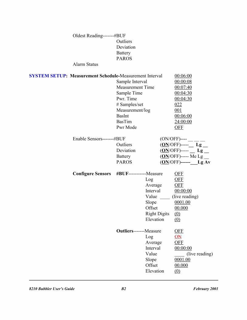
Figure 13: Pressure Control Unit Leak Testing
Figure 14: Leaking Fitting
APPENDIX CPROBLEMS WITH EQUIPMENT OR STATIONS DATA

8210 Bubbler User’s Guide February 2001C2
Figure 15: Wilmington Data Example
In the example above, the red tide curve is a bubbler type tide gauge. A leak starts andthe pressure drops in the bubbler line. This loss of pressure will sometimes drop all the way to 0psi. More often as the pressure drops, the leak will stop because the fitting is tight enough tohold the lower pressure, but not tight enough to contain a higher pressure associated with highertides. As the pressure increases, the leak recurs again starting the process over and over again. Aleak will sometimes only manifests itself in cold weather. As the temperature drops as shown inthe lower graph, the plastic bubbler tubing shrinks faster than metal fitting causing a leak. Thebest way to avoid temperature related leaks is to check the gauge before the orifice is installed. The 8210 tide gauge has self-closing quick disconnect fittings on both the input and output of thegauge. By connecting the input to a nitrogen tank and over-pressurize the system to 36 psi, thenturn off the valve on the nitrogen tank and wait 15 to 30 minutes. Check for any loss of pressure. If there is a loss of pressure look for the leak by removing the pressure control unit. It should benoted that the 8210 motherboard must be removed before removing the pressure control unit. Use a leak detection liquid like Snoop®, and look for the formation of bubbles around theleaking joint. Tighten that joint and test again. Figure 13 and 14 on back page show the leaktesting of the pressure control unit.

8210 Bubbler User’s Guide February 2001C3
Figure 17: Cedar Key Data Example
Figure 16: Waveland Data Example
The Waveland water level example shows a station that has run out of gas notice how there isstill a rise and fall of water levels but it dose not track the predicted and acoustic measurements.
The Cedar Key data graph shows a leaking fitting probably in the manifold assembly. As thepressure increases the leak starts, and then pressure drops, and then as pressure builds again theleak opens again.

8210 Bubbler User’s Guide February 2001C4
Figure 18: Newport News Data Example
Figure 19: Lewisetta Data Example
In this example for Newport News data graph either the tank pressure is getting low or the lowpressure feed is not great enough to follow the full tidal range. There just is not enough pressureto push the bubble out of the end of the orifice.
This is another example of a clogged or buried orifice at Lewisetta.

8210 Bubbler User’s Guide February 2001D1
APPENDIX DTROUBLESHOOTING GUIDE
In most cases, if there is a problem with a tide gauge that is not easily resolved, callPacific Regional Office, and get assistance from one of the technicians.
Display willnot light
1. Battery discharged or worn out. Check battery voltage for the display tolight. It needs to be greater than 9.5 volts. For the system to work correctly,the battery voltage should be greater than 12.0 volts.
2. Check the solar panel or external charger.
3. The system may be resetting. This could take several minutes.
4. Check fuses. The battery fuse is on the cover to the interconnect boardand a fuse that supplies power to the 8210 CPU board is located on theinterconnect board.
Display istoo dim.
To change the display brightness, press the "SET" key when the display is atthe top of the MAIN MENU.
No data inthe log(missingdata)
Recording is OFF in the main menu. Turn recording to ON.
If there is data from one or the other sensor, check the configured sensor tosee if the LOG option is switched on for the sensor that is not logging data.
If the log shows no PAROS data, change-out the tide gauge, and return it tothe Pacific Regional Office at Seattle.
8210 losingclock timewhen thebattery isdisconnected
Make sure the RAM battery on the CPU board is >2.6 volts.Check the battery jumper near the RAM battery, it should be on.
System runsfor a shorttime andthen resets
Possible low battery voltage.If problem persists return unit to factory.

8210 Bubbler User’s Guide February 2001D2
GOESTransmitterwill notTransmit
1. Using an external through-line watt meter, check forward power to theantenna or resistive load. There should be approximately 7-10 watts ofpower.
2. Check reflected power, it should be less than 2.5 watts
3. Using an ohm meter, check the resistance from the center pin of theantenna connector to the threaded shell of the same connector. It should havea DC resistance of less than 3 ohms.
4. Check the battery voltage. The battery should drop only 0.5 volts whenthe radio is transmitting. The battery voltage must be greater than 10.5 voltsand less than 14.9 volts for the transmitter to work.
5. Check the battery connection in the battery box. Make sure it is tight. Check the connecters. Make sure they are tight.
6. Look along the path of the GOES antenna. See if it is pointing at amountain, building, or trees. Any of these could block the signal fromreaching the satellite.
7. Make sure fail-safe has not tripped. Use system status display to check orlook at recording status. It will say "ON&FT" if the fail-safe is tripped. Toreset the fail-safe using the front panel, go to the recording status and pressSET until the FT goes away. There is also a hardware reset on the GOEStransmitter board near the ribbon cable. By momentarily pressing this button,the fail-safe should reset.
8. Check the fuse to the GOES transmitter board. There is an in-line fuse onthe power cable to the GOES transmitter.
Can nottransferdata to thePCMCIA(RAM) card
The RAM or PCMCIA data card has an internal battery. Check thisbattery. It should be greater that 2.8 volts.

8210 Bubbler User’s Guide February 2001D3
Fuses There are several fuses protecting the 8210 water-level gauge. The followinglist shows all the voltage protection devices for this unit. Fuses designatedRVx are thermal fuses and automatically reset when they cool off. Theycannot be changed in the field.
1. Interconnect board F1 1amp 3AG 12V to CPUboard
RV1, RV3 60ma RS85 protection RV2 .45 amp SDI-12 port +12V
2. CPU RV1 .66amp J1 pin 1 Aux +12V protection
RV2 .66amp Switched +12 Vprotection
3. GOES module In Line 5 amp 3AG +12 to Radio
4. Top panel interconnect Fuse left 6amp 3AG Solar panel fuse
5. Top panel interconnect Fuse Right 6amp 3AG Battery Fuse.
Antenna There are two types of antennas that may be encountered in the field.
The first is the Yagi type, which is a highly directional antenna that has atypical power gain of 9 to 12 dB. Effective power is doubled every 3 dB. Inother words, the signal at the receiver will be twice as strong if the antennahas a gain of 3 dB. This is due to the concentration of power created by thetightness of the beam from the antenna. A typical Yagi antenna has a beamof (20L) degrees.
The most common type of antenna that NOS uses for transmitting to GOESis the flat plate antenna. This antenna has a very wide beam (96L) and a gainof 3 dB. With a beam this wide, obstructions that are some distance awayhave little effect on the signal quality. The primary concern is that thereshould be a clear view of the satellite. If the satellite is behind a mountain,ship, or building, there is little chance that the signal will get through. Inaddition to keeping any objects out of the direct line-of-sight path to thesatellite, maintain at least a meter (3 feet) clearance on each side. It is also agood idea to maintain a distance of 1 meter (3 feet) from any other antennas. If the roof of the building is made of fiberglass, the antenna can be mountedinside.

8210 Bubbler User’s Guide February 2001D4
AntennaTesting
The inherent design of the Mod 14 antenna exhibits a dead short to dcvoltage. This can be seen by connecting an ohm meter from the outer shellof the antenna connector to the inter pin of the same connector. This shouldread less then 1 ohm.
When you test the antenna resistance in the field, disconnect the coaxialcable from the front of the hydro gauge. Measure from the center pin to theouter shell of the coaxial connector on the cable. This resistance issomewhat dependent on the length of the coaxial cable that you are using,but, the resistance should be less than 3 ohms.
If the resistance is greater than 3 ohms, the antenna should be replaced orrepaired. The resistance is due to corrosion either between the connection ofthe two internal antenna plates or in the coaxial cable and/or its connectors.Extremely high resistance is caused by a broken connection between the twoplates.
To test the antenna, remove it from the coaxial cable, and measure theresistance again.
AntennaCables, Connectors,and Mounting
NEVER coil the antenna cable. This will make the RF signal induce amagnetic field around the coil. When the field collapses into the cable, theinduced signal cancels the transmitted signal distorting the data quality.
Antenna connectors should be wrapped with "Scotch 130c liner less rubbersplicing tape"; then the connector is wrapped with "Scotch 33" blackelectrical tape; then painted with "Scotch Coat". This practice proved, fromyears of experience on the ships, to prevent any water from getting into theconnectors. The type of tape used is very important regarding connectors'ability to withstand extreme temperature changes.
A two-inch pipe works well to mount the antenna on. Typically, NOS uses a10-foot section, a "T" coupling, and a 6-foot section to mount the antennaand solar panels. The "T" junction is used to secure the pipe to the side ofthe tide house.

E1
APPENDIX EPNEUMATIC CONNECTIONS

8210 Bubbler User’s Guide February 2001F1
APPENDIX FCHANGING THE NITROGEN TANK
8210 Bubbler User’s Guide February 2001G1
APPENDIX GGAUGE PRESSURE PARAMETERS
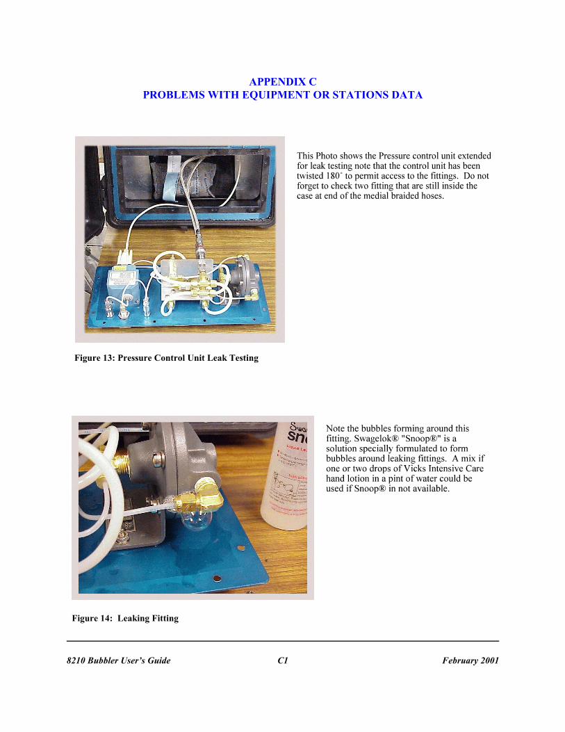
Generally the table given on Page 12 for up to 200 m tubing length and one given belowfor tubing length up to 500 m should be used to select the required feed pressure and flow meterscale settings once the maximum orifice depth and the maximum tidal range is known.
To use these tables, select (a) maximum orifice depth and (b) Maximum tidal range at thedeployment site and then the table will provide you information regarding (1) required feedpressure (2) Cole Parmer flow meter scale settings and (3) how many days approximately the 80cu ft nitrogen tank will last at those selected parameters. The intersection of maximum orificedepth value column and the maximum tidal range row will provide you with the Cole Parmerflow meter scale setting, then read the required feed pressure vertically in the same column in thetop second row (vertical intersection with Required Feed Pressure row); and from that flow meterscale setting read (horizontally) in the last column the approximate number of days the 80 cu ftnitrogen tank will last for the selected parameters.
TABLE OF PARAMETERS FOR TUBING LENGTH UP TO 500 METERS
Maximum Orifice Depth (meter)
0 to 10 10 to 15 15 to 20
Required Feed Pressure (psi)
18 25 32
Maximum Tidal Range(meter)
Cole Parmer Flow Meter Scale Settings
80 cu ft Nitrogen Tankwill last so many Days
0 to 4 18 17 15 126
4 to 6 26 24 22 84
6 to 8 32 30 28 63
8 to 10 NA 35 33 50
10 to 12 NA 40 37 42
Notes:
(1) The flow settings are 1.8 times the minimum flow required.
(2) NA implies the case is not applicable since tide range can not be greater than orifice depth.

8210 Bubbler User’s Guide February 2001G2
The following two tables are provided as general information. These tables can be used when there is a specific need to determine the flow meter settings in circumstances not coveredby the other two tables.
The table below provides the theoretical minimum flow rate for a given tidal range and tubinglength. The longer the bubbler tube is, the greater flow rate is required to maintain the nitrogenat the end of the orifice.
MINIMUM GAS FLOW RATE (CC PER MINUTE) @ STPLength of Tubing
Tidal Range 100 m 200 m 500 m 1000 m 2000 m 2 m 1 1 3 7 14 4 m 2 3 7 14 27 6 m 2 4 10 21 41 8 m 3 6 14 27 55 10 m 4 7 17 34 68 12 m 5 9 21 41 82
The orifice is 1 inch diameter and 7 inches tall and standard temperature and pressure areassumed for this computation.
To read the above table, select the tubing length and the tidal range at the deploymentsite, and at the intersection of these two will provide you the theoretical minimum gas flow ratein cc/min. Before using the next table, put a factor of safety, such as 1.8, on the minimum gasflow rate to obtain a desired gas flow rate.
Then using the next table, the intersection of this desired gas flow rate and the maximumorifice depth at the deployment site, will provide you the value of the flow meter scale setting. Read from this intersection of scale setting, vertically at the second top row the necessary supplypressure in psi, and horizontally in the last column the approximate days the 80 cu ft nitrogentank will last for these parameters.

8210 Bubbler User’s Guide February 2001G3
COLE PARMER FLOW METER SETTINGSFOR VARIOUS FLOW RATES AND SUPPLY PRESSURE COMBINATIONS
Maximum Orifice Depth (meter)
0 to 10 10 to 15 15 to 20
Required Feed Pressure (psi)
18 25 32
Desired gas flow @ STP(cc/min)
Cole Parmer Flow Meter Scale Settings
80 cu ft Nitrogen Tankwill last so many Days
5 6 5 4 315
10 14 13 12 157
15 21 19 18 105
20 27 24 23 79
25 32 29 27 63
30 36 33 31 52
35 40 37 35 45
40 44 41 38 39
Here is some relevant information:1 cubic (cu) foot = 28320 cubic centimeters (cc) 1 cu foot /Per Day = 19.67 cc/minuteNOS normally uses 80 cu foot size of nitrogen cylinders for hydro applications.

8210 Bubbler User’s Guide February 2001G4

8210 Bubbler User’s Guide February 2001G5