Embed Size (px)
Citation preview

KELSY
USER’S GUIDE

CONTENT
1. INTRODUCTION ............................................................................................ 3
2. COMPONENTS ............................................................................................... 3
3. SYSTEM REQUIREMENTS.......................................................................... 3
4. WARNING........................................................................................................ 4
5. HARDWARE SPECIFICATION................................................................... 4
5.1. Parameters of scanner KELSY.................................................................... 4
5.2. Parameters of the video capture device ...................................................... 4
6. SOFTWARE SPECIFICATION .................................................................... 6
6.1. KelsyTE .......................................................................................................... 6
7. PREPARATION FOR THE WORK ............................................................. 7
7.1. Installing the video capture device drivers ................................................. 7
7.2. Installing KelsyTE program......................................................................... 8
7.3. KELSY scanner connection.......................................................................... 8
8. KelsyTE. The user's guide ............................................................................... 9
8.1. Starting KelsyTE ........................................................................................... 9
8.1.1. The main window ....................................................................................... 9
8.1.2. The main menu ......................................................................................... 10
8.1.3. The list of personnel’s .............................................................................. 12
8.1.4. Area of a print........................................................................................... 13
8.1.5. Tools bar.................................................................................................... 14
8.1.6. Status bar .................................................................................................. 14
8.2. Data input..................................................................................................... 15
8.3. Printing......................................................................................................... 23
8.4. Results saving............................................................................................... 24
9. MAINTENANCE SERVICE ........................................................................ 25
9.1. Service instructions ..................................................................................... 25
9.2. Certificate on acceptance............................................................................ 26
9.3. Manufacturer's guarantees ........................................................................ 26
2

1. INTRODUCTION
Kelsy System is intended for input, processing and store kirlian’s images, also print on their base the individual cards with additional demographic information. Kelsy system also allows to receive kirlian’s images both organic, and inorganic objects. For input of images are used scanners of series KELSY - devices for discharge visualization on effect Kirlian (see Fig.1) and the video capture device AverMedia (connected to USB 2.0 port of computer or to PCI slot). Software works under Windows98 SE/2000/ХР operation systems.
2. COMPONENTS 1. Scanner KELSY - 1
2. CD - disk with KelsyTE software - 1
3. Video capture device AverMedia EZMaker and CD -
disk with drivers
- 1
4. User’s guide - 1
5. Cable for video signal - 1
6. Test object - 1
7. Sleeve of blackout - 1
8. External Power source 12 Volt AC, 1.8A - 1
3. SYSTEM REQUIREMENTS Operational system Windows 98SE/2000/XP (it is recommended Windows XP) The processor Not below Pentium III 600MHz RAM Not less 128Мбайт Places on a hard disk Not less 1Г byte (free space at the rate of 3Мб on one
individual card) CD ROM 4-x high-speed and is higher The device for video capture WDM-compatible for Windows 98/2000/XP Program maintenance Established software DirectX 8.0 and is higher The printer Should be installed in system by the default printer USB port Free USB 2.0 port
3

4. WARNING • At work it is strictly forbidden to power on scanner KELSY without connection grounded
wires to grounding connector on the scanner case. • Do not attempt to disassemble or alter any part of the equipment. • Stop operating the equipment immediately if it emits smoke or noxious fumes. • Stop operating the equipment if it is dropped or the casing is damaged/ • All cables to connect into sockets of the scanner only at the power switched off. • At installation of a finger on a surface of an optical window in scanner KELSY do not touch
the second hand of grounded subjects. • Button “Start” press only after installation of objects on a surface of an optical window.
Object the finger of the person or other grounded subject for research may be. • At installation of a finger on a surface of an optical window in scanner KELSY it is not
necessary to put effort and to press on a contact surface. For reception of the precise image enough an easy dense contact a finger of a contact surface.
• Button " Start " to hold in the pressed condition no more than 20 seconds. Repeated pressing of button " Start " to make not less than in 30 seconds.
• It is not supposed to hold at the included feed of the scanner long time an optical window in the closed (blacked out) condition.
5. HARDWARE SPECIFICATION
5.1. Parameters of scanner KELSY
- Power source 12 Volt AC - Resolution of TV camera not less than 460 TVL - Type of video signals CCIR black/white TV-signal
5.2. Parameters of the video capture device
- Speed (FPS) 10-30 - Compatibility Windows 98/2000/XP - Type USB port USB 2.0 - Type PCI slot PCI 2.1 - Video inputs Composite, S-Video
4

1. “GROUND” connector 2. Switch “POWER” 3. “VIDEO” connector 4. “Remote Control” connector 5. Button “START” 6. Button for frequency select 7. LED of voltage indicator 8. “Power” connector 9. Optical window
Fig.1. Scanner KELSY
10. Device for biological objects testing
5

6. SOFTWARE SPECIFICATION
6.1. KelsyTE
For installation of program KelsyTE it is necessary to copy from CD disk catalogue Kelsy\Software\KelsyTE on a disk of your computer. The software is submitted as the basic executed module and a database, and also auxiliary executed modules and other files.
For program start use a file KelsyTE.exe. Before start of the program to read recommendations on the installation, specified in section
“KelsyTE. The user’s guide” (see further)
With KELSY system probably is carrying out of researches a various organic and inorganic objects.
Program complex KELSY TE is a part of system for reception the electronic images, intended for input, processing and store kirlian’s images, also print on their base the individual cards with the additional demographic information. For input of images are used scanners of series KELSY - devices for discharge visualization on effect Kirlian.
KELSY TE solves the following tasks: • supervision in real time the image received from scanner KELSY • input of images with averaging on the set number of the frame and coloring in colors
from the set palette • carrying out of the spectral analysis at work with the color camera • input and save of the demographic data in a TXT file • save of the received video images in AVI files • save of the received image as sequence of 10 separate frames • save of the received images in BMP files according to the entered demographic data • conclusion to a printer of the saved images and the corresponding demographic data:
• surname, name; • date of birth; • scan date; • special marks.
6

7. PREPARATION FOR THE WORK
For the beginning works with hardware-software complex KELSY it is necessary to execute the following steps: 1. To check up conformity of technical parameters of your computer to the system requirements
resulted in section “ System requirements ” (see item 3.); 2. If necessary to install on your computer software DirectX 8.0 and is higher; 3. Insert video capture device in free port/slot of computer. 4. To lead installation of video capture device drivers according to the recommendations
specified in section “ Installing the video capture device drivers ” (see further); 5. To lead installation of KelsyTE software on your computer according to the
recommendations specified in section “ Installing KelsyTE program” (see further); 6. Attentively read the basic operating modes of a complex, which are specified in section
“KelsyTE. The user's guide ”; 7. Connect of KELSY scanner according to the recommendations specified in section “KELSY
scanner connection” (see further); 8. Start of KelsyTE software and to check up serviceability of all hardware-software complex
KELSY.
7.1. Installing the video capture device drivers
1. At the first loading a computer from OS Windows 2000/XP the dialogue window of master utility - Found New Hardware Wizard would appear. Press button Next;
2. Choose automatic search of the updated drivers. Press button Next; 3. Choose function of installation of drivers from CD ROM. Insert an install disk of the video
capture device into CD ROM. Press button Next; 4. At this stage the master of installation will find out necessary the driver. Press button Next; 5. Ignore warning message. Press Yes and continue installation of components; 6. Press Finish. Further installation of drivers for audio and TV-a tuner will be continued if
necessary; 7. Restart a computer. 8. After restart a computer in case of successful installation drivers in system menu of your
computer the menu item for start of standard programs of the video capture device will appear.
9. Connect to an input of the video capture device any source of video signal. Start the standard program for viewing video signal from the video capture device.
10. Be convinced of serviceability of the installed device. 11. If the installed video capture device does not give a correct picture at work with the standard
software repeat procedure of drivers installation of the video capture device, preliminary having removed from a computer the driver of other video capture devices.
7

7.2. Installing KelsyTE program
For installation of KelsyTE program on your computer it is necessary to execute the following steps: 1. To insert CD disk with KelsyTE software into the CD ROM drive of your computer; 2. Copy from CD disk the catalogue \Kelsy\Software\KelsyTE on a disk of your computer; 3. For start of the program to use a file KelsyTE.exe. 4. If it is necessary to exchange working catalogue in which kirlian’s images and personal data
will be save. Attention: For remote of KelsyTE software from your computer it is necessary to remote catalogue KelsyTE from a computer. And if the working catalogue was changed also delete this directory.
7.3. KELSY scanner connection
For connection of KELSY scanner it is necessary to execute the following steps: 1. To ground the scanner, through connector "Ground" on an obverse surface of the device; 2. To connect a cable of video signal by one end to an input of the video capture device (it is
recommended to use inputs S-Video (at work with black-white cameras) and Composite (at work with color cameras), and the second end to a connector "Video" on an obverse surface of the device;
3. To connect a power cable from Power source 12 volt, 1.8 A, AC; 4. To turn on power of the scanner and to check up presence of a power on the red indicator on
an obverse surface of the device; 5. After turn on power (before pressing button " Start ") in a working window of program
KelsyTE it is possible to observe video signal from the camera. 6. Before the beginning of working attentively read safety precautions requirements, see item 4
«Warning» ATTENTION. It is forbidden to use the scanner without protective grounding. ATTENTION. Button " Start " press only after installation of objects a surface of an optical window. Object the finger of the person or other grounded subject for research may be.
8

8. KelsyTE. The user's guide
8.1. Starting KelsyTE
Program complex KELSY TE is a part of system for reception of the electronic images, intended for input, processing and save kirlian’s images, and also a print on their basis of individual cards with the additional demographic information ("Name", " Date of a birth ", "Date of filling of a card ").
8.1.1. The main window
Main window KELSY TE (see Fig. 2) will consist of the following parts: • the main menu • the list of personnel’s • area of a print • tools bar • status bar
Fig. 2. KELSY TE. Main window
9

8.1.2. The main menu
• "File" • "View" • "Edit" • "Help"
["File"] The menu "File" (see Fig. 3) contains the following items: • " Change archive folder... " • " Export... " • " Print... " • " Print preview " • " Print setup... " • " Exit"
Fig. 3. Menu "File"
Item " Change archive folder... " it is intended for change of a place in which the archive data of images are save.
Item " Export... " it is intended for export of a personal card. In the selected place the files of initial images and files of a personal card images and text file with the personal data will be created.
Item " Print... " is intended for a print output of a personal card. It also can be caused on "Ctrl+P" or with the tools bar button.
Item " Print preview " is intended for preliminary viewing listing. The item is accessible only if in Windows system the printer is installed.
Item " Print setup... " is intended for setting the printer and printer properties.
Item "Exit" is intended for an exit from the program. It also can be caused on Alt + F4.
["View"]
The menu "View" (see Fig. 4) contains the following items: • " Language" • " Aura" • " Zoom In " • " Zoom Out "
10

Fig. 4. Menu "View"
Submenu "Language" it is intended for setting the language of the interface and systems help.
The choice of item "Aura" makes inclusion of aura display in the area of a print.
Item " Zoom In " it is intended for increase the images in the area of a print. It also can be caused on Ctrl + "+".
Item " Zoom Out " it is intended for reduction the images in the area of a print. It also can be caused on Ctrl + "-".
[Edit] The menu "Edit" (see Fig. 5) contains the following items: • " New record " • " Delete record " • " Personal information " • " Calculate Aura "
Fig. 5. Menu "Edit"
The command " New record " is intended for creation of a new individual card. It also can be caused on "Ctrl+N" or with the tools bar button.
Editing of the text data of an individual card is made at work with a window "Data input" (see Fig. 11)
The command " Delete record " is intended for deleting selected individual card. It also can be caused on "Del" or with the tools bar button.
The command " Personal information " is intended for start of filling individual card procedure. It also can be caused on "F7" or with the tools bar button. The given command is active, when record in the list of personnel’s is chosen.
The command " Calculate Aura " is intended for start of aura calculation procedure. It also can be caused on "F5". The given command is active only if for selected personnel’s record presents all 10 (ten) kirlian’s images.
11
["Help"] The menu "Help" (see Fig. 6) contains the following items: • “ About... ” • “ Help... ”
Fig. 6. Menu "Help"
Item “ About... ” it is intended for showing the version of the program.
Item “ Help... ” is intended for a call of help system. It also can be caused on F1.
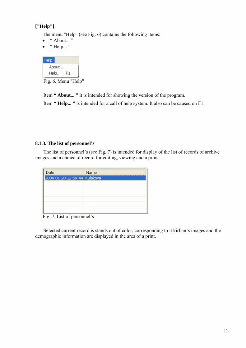
8.1.3. The list of personnel’s
The list of personnel’s (see Fig. 7) is intended for display of the list of records of archive images and a choice of record for editing, viewing and a print.
Fig. 7. List of personnel’s
Selected current record is stands out of color, corresponding to it kirlian’s images and the demographic information are displayed in the area of a print.
12

8.1.4. Area of a print
Area of a print (see Fig. 8) it is intended for display kirlian’s images and the demographic information, corresponding to the current record of the list of personnel’s.
Fig. 8. Area of a print
For a call of a window "Data input" use double click on the kirlian’s image.
For load / unload of aura image use a command "Aura" of the tools bar.
13

8.1.5. Tools bar
Tools bar (see Fig. 9) duplicates, accordingly, the following items of the menu: • "Print" (the Menu "File") • "New record" (the Menu "Edit") • "Delete record " (the Menu "Edit") • "Personal information " (the Menu "Edit") • "Aura" (the Menu "View")
Fig. 9. Tools bar
Also the tools bar contains switch " Aura " intended for load / unload of aura image in the area of a print.
8.1.6. Status bar
Status bar (see Fig. 10) displays the current information on the chosen item of the menu and the button of the control panel.
Fig. 10. Status bar
14

8.2. Data input
For creation of a new individual card the command " New record " the menu "Edit" is intended. It also can be caused on "Ctrl+N" or with the tools bar button.
For start of procedure of filling of an individual card the command " Personal information " the menu "Edit" is intended. It also can be caused on "F7" or with the tools bar button. The given command is active, when record in the list of personnel’s is selected. Also the window "Data input" can be caused by mouse double click on any image in the area of a print.
In a window "Data input" (see Fig. 11) is carried out filling an individual card.
Fig. 11. "Data input" window
For each card there is an opportunity to specify "Name", " Date of birth ", "Scan Date". The choice of a finger for the subsequent scanning is carried out by the switch 1L-5R (the 1L-left big finger, the 5R-right little finger). At work switching between finger indexes 1L-5R is made automatically.
The area of the current video image is located on left side, and area of the scan image - from the right side of a window.
15

The menu "Video" (see Fig. 12) contains the commands intended for adjustment of input video signal. The bottom items of the menu allow choosing used video capture device from several, installed on the given computer. Item " Video Source... " allows choosing a required video source input if the device have more than one video input. Items " Video Settings " and "Video Format... " are intended for adjustment of parameters for input video signal.
Attention: Recommended parameters of input video signal: a format 352х288, TV standard
PAL-D. Attention: The item of the menu " High Speed camera... " is used, only if in system
installed camera working with interface IEEE-1394. Such camera does not include into the base complete set of device.
Fig. 12. Menu "Video"
Button " Scan " is intended for capture and save the current image. Parameters of the save image (“ Use palette ”, “ White BG ”, " Noise threshold ") are set in area of " Image settings". Parameters can be save by the button " Save settings " and subsequently are restored by the button " Load settings ".
Attention: After pressing button " Scan " in a right window (area of the save image) for short time of 2-3 seconds the scanned image will appear. Then program automatically make choice of the following finger (show change of a condition of switches 1L-5R) and the current scanned image window will clear. Viewing of the current scanned image is carried out by a repeated choice of the necessary switch 1L-5R.
Button "Scan" is recommended to be press after performance of the following steps:
1. To establish a finger (or other grounded subject) on a surface of an optical window of the scanner;
2. To press button " Start " of the scanner
3. To keep button " Start " in the pressed condition up to reception of a stable picture on brightness kirlian’s images in the current video image window (but no more than 20 seconds);
4. To press button " Scan ". In the field of the save image will appear kirlian’s image;
5. To release button " Start " of the scanner. Have pressed button " Stop ".
6. It is recommended to do retake of the new image not earlier than 30 seconds after end of the previous shooting.
16

The button "10" is intended for capture and saving of the current image of sequence from 10 frame. Capture Speed of sequence of the frames is defined by computing capacity of your computer. Viewing of the scanned images is carried out by a choice of the necessary switch 1L-5R.
The button “ Start AVI ” is intended for select AVI files directory and for record in AVI file the video from area of the current video image. For correct record AVI file in the menu "AVI" the item “ Color format ” should be chosen.
Fig. 13. Menus of AVI files record modes
The stop of record is made by pressing of the button “ Stop AVI ”. Attention, that record AVI files is made in full not compressing format (1 second of record occupies approximately 10М byte of disk space).
In area “ Capture Settings ” also you can see the additional parameter:
• FPS – number of the video frame acting from a video camera in a computer per 1 second.
The parameter "N of averaging frames" carries out averaging the image by set quantity of the frame and is intended for increase of input image stability and decrease in a level of noise. Recommended value – 5.
"Cutting area" is set in a case when it is required to allocate a site of the image, having removed his some part on edges (for example, for struggle against " side effects ").
The area " Image settings " gives an opportunity to use a white background, to change the received image coloring and to set displacement in a palette for noise reduction of the received image.
The parameter " Noise threshold " is intended for decrease in a noise level. The noise threshold factor defines a level of brightness, values are lower which are considered background and are not taken into account at image scanning. In the program exists the mode of automatic definition of a noise threshold " Auto Calculation ".
The choice of the switch " White BG " allows to choose background color in the scanned image.
17

In addition the opportunity to load an alternative palette for scanned image coloring is given the user or to refuse in use of a palette for coloring (see Fig. 14). For loading a new palette (from a file with extension *.pal) it is necessary to press the button "Load" and to choose a required file. For refusal in use of a palette it is necessary to switch off " Use palette ".
Fig. 14. Window of supervision ( the switch “ Use palette” is switched off)
18

The area "Colors" gives an opportunity at work with a color video camera to carry out the spectral analysis of the image.
By pressing button " L " the window (see Fig. 15), in which the length of a wave corresponding to color of pixel under the mouse pointer and three next pixels, is shown.
By pressing button "H" the window of the waves lengths histogram will be showed (see Fig. 16). In this window for the scan image which is on the right side of the window, the histogram of distribution quantity of pixels with wave length, determining their color will be constructed.
Fig. 15. Window for measurement of wave length corresponding to color of pixel under the
mouse pointer. (Mouse pointer position is allocated by white circle.)
19

Fig. 16. Window of the waves lengths histogram
At inclusion of the switch "Filter C" at construction of histograms is made multiplying brightness of a point on weight factor. (The more brightly point on the screen is the more significant at construction of histograms.)
At inclusion of switch "Filter S" at construction of histograms and at definition of wave length there is a removal of points, at which around points – black. (i.e. remove single points).
20

The choice of switches " Isochromatic lines 10 % " and " Lines Only " allows to observe isochromatic lines connecting points with equal brightness (see Fig. 17, 18). Lines are build for all values of brightness with step 10 %.
Fig. 17. Isochromatic lines are constructed atop of the scanned image. (the switch
"Isochromatic lines 10 % " is switched on, the switch “Lines only” is switched off)
21

Fig. 18. Isochromatic lines are constructed atop of the scanned image. (the switch
"Isochromatic lines 10 % " is switched on, the switch “Lines only ” is switched on)
22

8.3. Printing
For a conclusion to print of an individual card the command "Print... " the menu "File" is
intended. It also can be caused on "Ctrl+P" or with the button on tools bar. Before a call of a command " Print... " it is necessary to select corresponding record in the list of personnel’s. Thus in the field of a print the corresponding demographic data and kirlian’s images will be displayed.
For preliminary viewing listing (see Fig. 19) intend a command "Print preview" the menu "File".
For a select of the printer and printer parameters adjustment the command "Print setup... " the menu "File" is intended.
Fig. 19. Window of previewing
23

8.4. Results saving
All created individual cards and archives of images are save automatically in the catalogue
which has been specified in item " Change archive folder... " the menu "File". For each individual card the own subdirectory is created, in which the information on the patient and it kirlian’s images as BMP files with names 1L-5R (in conformity the chosen switch 1L-5R, the 1L-left big finger, the 5R-right little finger (see Fig. 10)) is saved.
In addition the opportunity record of video signal in AVI file is given to the user. For the beginning records and a select AVI file directory are necessary for pressing the button “ Start AVI ”. The stop of record is made by pressing the button “ Stop AVI ”. Attention, that record AVI files is made in full not compressing format (1 second of record occupies approximately 10М byte of disk space).
24

9. MAINTENANCE SERVICE
During the use recommended to make maintenance service of system KELSY simultaneously with maintenance service РС.
9.1. Service instructions
• Power source for scanner KELSY: 12 volts AC, 1.8A. • Operations and store temperatures: from +50С up to +400С
• Relative humidity: no more than 70 % at temperature +200С
• Mechanical impacts and vibrations is not supposed.
• Neutron and γ-Radiation is not supposed.
• Mechanical influence by extraneous subjects on a surface of an optical window of the
scanner is not supposed.
• Using the scanner without protective grounding is not supposed.
• All cables are connected only at the switched off power of the scanner.
• At work for reception high-quality kirlian’s images it is recommended to close object and the
scanner from influence of external light.
• Button " Start " press only after installation of object on a surface of an optical window.
• Button " Start " to hold in the pressed condition no more than 20 seconds. Repeated pressing
of button " Start " to make not less than in 30 seconds.
• It is not supposed to hold an optical window in the closed (blacked out) condition long time
at the “power on” state.
• In timeout between sessions of reception kirlian’s images it is necessary to switch off a
power of the scanner.
25

9.2. Certificate on acceptance
System KELSY № _612_ is recognized suitable for operation. Date of issue 12.2006 The signature of the person, responsible for acceptance___________________ Vice director ELSYS Corp. Minkin V.A.
9.3. Manufacturer's guarantees
The enterprise the manufacturer guarantees non-failure operation of system KELSY at observance of the service regulations established in the given description, and absence of mechanical damages, within 1 year.
Attention! Information in this document is subject to change without notice.
Dispose of this product in accordance with Local and National Disposal Regulations. Contact us: ELSYS Corp. Russia, 194223. Saint Petersburg, prospect M. Toreza, 68 phone/fax: +7 812 5526719 E-Mail: [email protected] www.elsys.ru
26