Embed Size (px)
Citation preview

BNI PNT-104-105-Z015
BNI PNT-202-105-Z015
BNI PNT-206-105-Z015
BNI PNT-302-105-Z015
BNI PNT-305-105-Z015
IP67 Modules
User’s Guide

www.balluff.com 1
Content
1 Notes 3 1.1. Structure of the guide 3 1.2. Typographical Conventions 3
Enumerations 3 Actions 3 Syntax 3 Cross-references 3
1.3. Symbols 3 1.4. Abbreviations 3 1.5. Deviating views 3
2 Safety 4 2.1. Intended use 4 2.2. Installation and startup 4 2.3. General safety notes 4 2.4. Resistance to aggressive substances 4
Hazardous voltage 4
3 Getting Started 5 3.1. Module overview 5 3.2. Mechanical connection 6 3.3. Electrical connection 6
Power Supply 6 Grounding 6 PROFINET Interface 6 I/O-Port 7 Port 7
4 Technical data 8 4.1. Dimensions 8 4.2. Mechanical data 8 4.3. Operating conditions 8 4.4. Electrical data 8 4.5. PROFINET 9 4.6. Function indicators 9
Module status 9 I/O Port 9
5 Integration 10 5.1. Configuration 10
GSDML file 10 Integration of the module 10
Configuration of the header module 11 Hardware configuration 12 Device name, Profinet address 13 Establishing device relationship 14 Assigning device name 14 Concluding the configuration 15
5.2. Functions in module properties 15 Module settings 15 Port functions 15 Safe state 15
5.3. Bit mapping and function 16 Inputs pin 4 16 Inputs pin 2 16 Outputs pin 4 16

www.balluff.com 2
Outputs pin 2 16 Actuator shutdown pin 4 / pin 2 16 Actuator warning pin 4 / pin 2 16 Restart pin 4 / pin 2 16 Peripheral error, socket 17 Short-circuit 17 Sensor supply 17 Station diagnostics 17
6 Diagnostics 18 6.1. Diagnostics message 18 6.2. Block Header 19
Block Type 19 Block Length 19 Block Version High 19 Block Version Low 19 Alarm Type 19 API 19 Slot 19 Subslot 19 Module ID 20 Submodule ID 20
6.3. AlarmSpecifier 20 Sequence Number 20 Channel Diagnostic 20 Manufacturer-Specific Diagnosis 20 Submodules 20 Diagnostic State 20 ARDiagnosis State 20 User Structure ID 20
6.4. Channel Number 21 6.5. Channel Properties 21
Type 21 Accumulative 21 Maintenance 21 Specifier 22 Direction 22
6.6. Channel Error Type 22
7 Webserver 23 7.1. General Information 23 7.2. Navigation / Info 24 7.3. Login/Logout 25 7.4. "Home" dialog 26 7.5. "Config" dialog 28 7.6. "Log" dialog 30
8 Monitoring & Diagnostics 31 8.1. General 31 8.2. SNMP MIBs 31
9 Appendix 33 9.1. Included material 33 9.2. Order code 33 9.3. Order Information 33
Notes 34
Balluff Network Interface Profinet
www.balluff.com 3
1 Notes
1.1. Structure of the guide
The guide is organized so that the chapters build on one another Chapter 2: Basic safety information Chapter 3: Getting started Chapter 4: Technical data ….
1.2. Typographical
Conventions The following typographical conventions are used in this Guide.
Enumerations Enumerations are shown in list form with bullet points.
Entry 1,
Entry 2.
Actions Action instructions are indicated by a preceding triangle. The result of an action is indicated by an arrow.
Action instruction 1. Action result. Action instruction 2.
Procedures can also be shown as numbers in brackets. (1) Step no. 1 (2) Step no. 2 (3)
Syntax Numbers:
Decimal numbers are shown without additional indicators (e.g. 123), Hexadecimal numbers are shown with the additional indicator hex (e.g. 00hex) or with the prefix “0x” (e.g. 0x00)
Cross-references
1.3. Symbols Note
This symbol indicates general notes.
Attention!
This symbol indicates a security notice which most be observed.
1.4. Abbreviations BNI Balluff Network Interface
I Standard input port PNT ProfiNet™ EMC Electromagnetic Compatibility FE Function ground O Standard output port
1.5. Deviating views Product views and illustrations in this manual may differ from the actual product. They are
intended only as illustrative material.
www.balluff.com 4
2 Safety
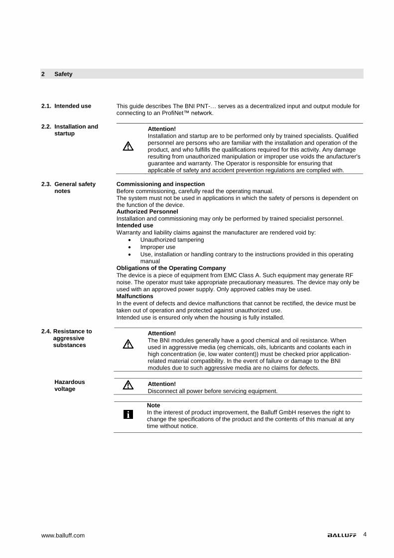
2.1. Intended use
This guide describes The BNI PNT-… serves as a decentralized input and output module for connecting to an ProfiNet™ network.
2.2. Installation and
startup Attention!
Installation and startup are to be performed only by trained specialists. Qualified personnel are persons who are familiar with the installation and operation of the product, and who fulfills the qualifications required for this activity. Any damage resulting from unauthorized manipulation or improper use voids the anufacturer's guarantee and warranty. The Operator is responsible for ensuring that applicable of safety and accident prevention regulations are complied with.
2.3. General safety
notes Commissioning and inspection
Before commissioning, carefully read the operating manual. The system must not be used in applications in which the safety of persons is dependent on the function of the device. Authorized Personnel
Installation and commissioning may only be performed by trained specialist personnel. Intended use
Warranty and liability claims against the manufacturer are rendered void by:
Unauthorized tampering
Improper use
Use, installation or handling contrary to the instructions provided in this operating manual
Obligations of the Operating Company
The device is a piece of equipment from EMC Class A. Such equipment may generate RF
noise. The operator must take appropriate precautionary measures. The device may only be
used with an approved power supply. Only approved cables may be used. Malfunctions
In the event of defects and device malfunctions that cannot be rectified, the device must be
taken out of operation and protected against unauthorized use.
Intended use is ensured only when the housing is fully installed.
2.4. Resistance to aggressive substances
Attention!
The BNI modules generally have a good chemical and oil resistance. When used in aggressive media (eg chemicals, oils, lubricants and coolants each in high concentration (ie, low water content)) must be checked prior application-related material compatibility. In the event of failure or damage to the BNI modules due to such aggressive media are no claims for defects.
Hazardous voltage
Attention!
Disconnect all power before servicing equipment.
Note
In the interest of product improvement, the Balluff GmbH reserves the right to change the specifications of the product and the contents of this manual at any time without notice.
Balluff Network Interface Profinet
www.balluff.com 5
3 Getting Started
3.1. Module overview
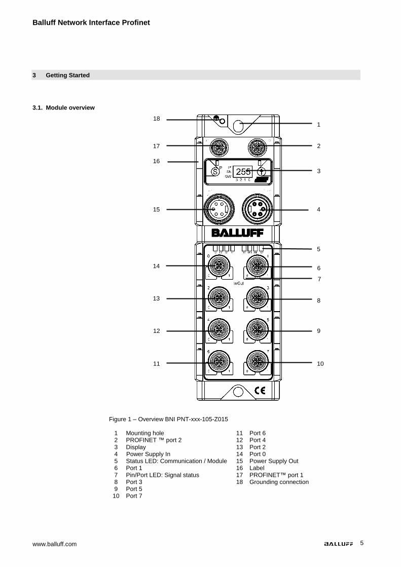
Figure 1 – Overview BNI PNT-xxx-105-Z015 1 Mounting hole
2 PROFINET ™ port 2 3 Display 4 Power Supply In 5 Status LED: Communication / Module 6 Port 1 7 Pin/Port LED: Signal status 8 Port 3 9 Port 5 10 Port 7
11 Port 6 12 Port 4 13 Port 2 14 Port 0 15 Power Supply Out 16 Label 17 PROFINET™ port 1 18 Grounding connection
1
6
2
3
12
11
13
14
15
18
8
10
7
9
17
16
5
4
www.balluff.com 6
3 Getting Started
3.2. Mechanical connection
The module is attached using 2 M6 screws and 2 washers. Isolation pad as accessory available
3.3. Electrical
connection
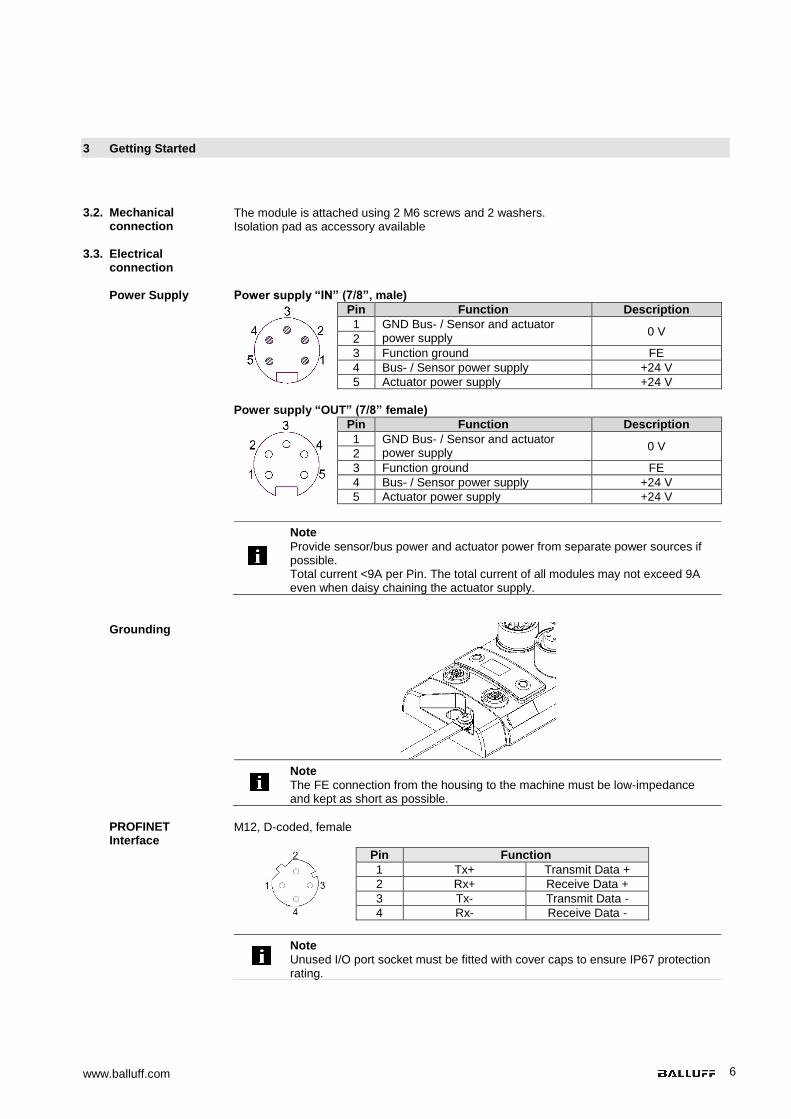
Power Supply Power supply “IN” (7/8”, male)
Pin Function Description
1 GND Bus- / Sensor and actuator power supply
0 V 2
3 Function ground FE
4 Bus- / Sensor power supply +24 V
5 Actuator power supply +24 V
Power supply “OUT” (7/8” female)
Pin Function Description
1 GND Bus- / Sensor and actuator power supply
0 V 2
3 Function ground FE
4 Bus- / Sensor power supply +24 V
5 Actuator power supply +24 V
Note
Provide sensor/bus power and actuator power from separate power sources if possible. Total current <9A per Pin. The total current of all modules may not exceed 9A even when daisy chaining the actuator supply.
Grounding
Note
The FE connection from the housing to the machine must be low-impedance and kept as short as possible.
PROFINET Interface
M12, D-coded, female
Pin Function
1 Tx+ Transmit Data +
2 Rx+ Receive Data +
3 Tx- Transmit Data -
4 Rx- Receive Data -
Note
Unused I/O port socket must be fitted with cover caps to ensure IP67 protection rating.
Balluff Network Interface Profinet
www.balluff.com 7
3 Getting Started
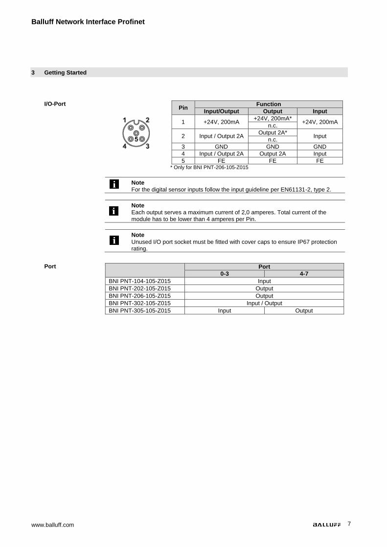
I/O-Port
Pin
Function
Input/Output Output Input
1 +24V, 200mA +24V, 200mA*
+24V, 200mA n.c.
2 Input / Output 2A Output 2A*
Input n.c.
3 GND GND GND
4 Input / Output 2A Output 2A Input
5 FE FE FE
* Only for BNI PNT-206-105-Z015
Note
For the digital sensor inputs follow the input guideline per EN61131-2, type 2.
Note
Each output serves a maximum current of 2,0 amperes. Total current of the module has to be lower than 4 amperes per Pin.
Note
Unused I/O port socket must be fitted with cover caps to ensure IP67 protection rating.
Port
Port
0-3 4-7
BNI PNT-104-105-Z015 Input
BNI PNT-202-105-Z015 Output
BNI PNT-206-105-Z015 Output
BNI PNT-302-105-Z015 Input / Output
BNI PNT-305-105-Z015 Input Output
www.balluff.com 8
4 Technical data
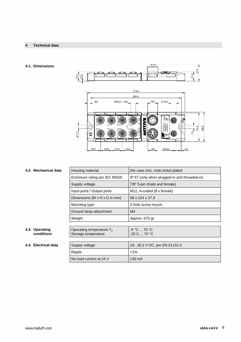
4.1. Dimensions
4.2. Mechanical data Housing material Die case zinc, matt nickel plated
Enclosure rating per IEC 60529 IP 67 (only when plugged-in and threaded-in)
Supply voltage 7/8” 5-pin (male and female)
Input ports / Output ports M12, A-coded (8 x female)
Dimensions (W x H x D in mm) 68 x 224 x 37.9
Mounting type 2-hole screw mount
Ground strap attachment M4
Weight Approx. 670 gr.
4.3. Operating conditions
Operating temperature Ta
Storage temperature -5 °C ... 70 °C -25 C ... 70 °C
4.4. Electrical data Supply voltage 18...30.2 V DC, per EN 61131-2
Ripple <1%
No-load current at 24 V 130 mA

Balluff Network Interface Profinet
www.balluff.com 9
4 Technical data
4.5. PROFINET PROFINET port 1 x 10Base-/100Base-Tx
Connection for PROFINET port M12, D-coded
Cable types per IEEE 802.3 Shielded twisted pair min. STP CAT 5/ STP CAT 5e
Data transmission rate 10/100 Mbit/s
Max. cable length 100 m
Flow control Half Duplex/Full Duplex (IEEE 802.33x-Pause)
4.6. Function
indicators
Module status LED Status Function
US green Input power OK
red Low Input power (<18V)
UA green Output power OK
red Low Output power (< 18V)
SF
off No error
red Watchdog timeout; channel, generic or extended diagnosis present; system error
red flashing DCP signal service is initiated via the bus
BF
off No error
red No configuration; or low speed physical link; or no physical link
red flashing No data exchange
100 off Bus clock: 10 Mbit/s
yellow Bus clock: 100 Mbit/s
LK green Data transfer
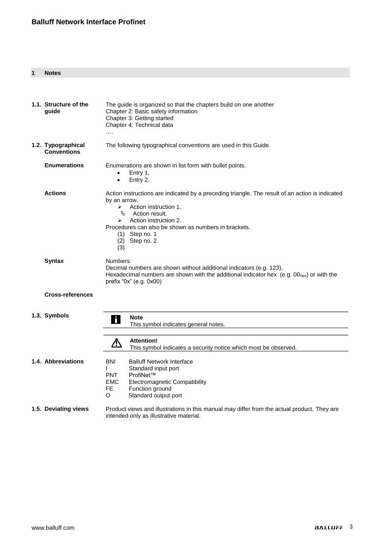
I/O Port Each port has two two-colour LEDs to indicate the I/O-States
Status Function Description
off I/O State State of the Input or Output Pin is 0
yellow I/O State State of the Input or Output Pin is 1
Status Port configuration
Diagnostic Input Input Output
red Input low short-circuit between
Pin 1 und 3 short-circuit on output
Pin
red flashing
_ _ short-circuit between
Pin 1 und 3
Status LEDs
Port LEDs
www.balluff.com 10
5 Integration
5.1. Configuration
When planning Profibus devices, a device is depicted as a modular system with a header module and several data modules. The screenshots shown here have been taken from the configuration software of the Siemens HW config.
GSDML file
The device data required for project planning is saved in GSDML files (Generic Station Description Markup Language). The GSDML files are available in two languages as an
Internet download (www.balluff.com). The data modules of an IO-Link block are displayed in the project planning software according to the slot. The GSDML file makes the possible data modules available (input or output of different data ranges). For configuration of the IO-Link blocks, the corresponding data modules are assigned to a slot.
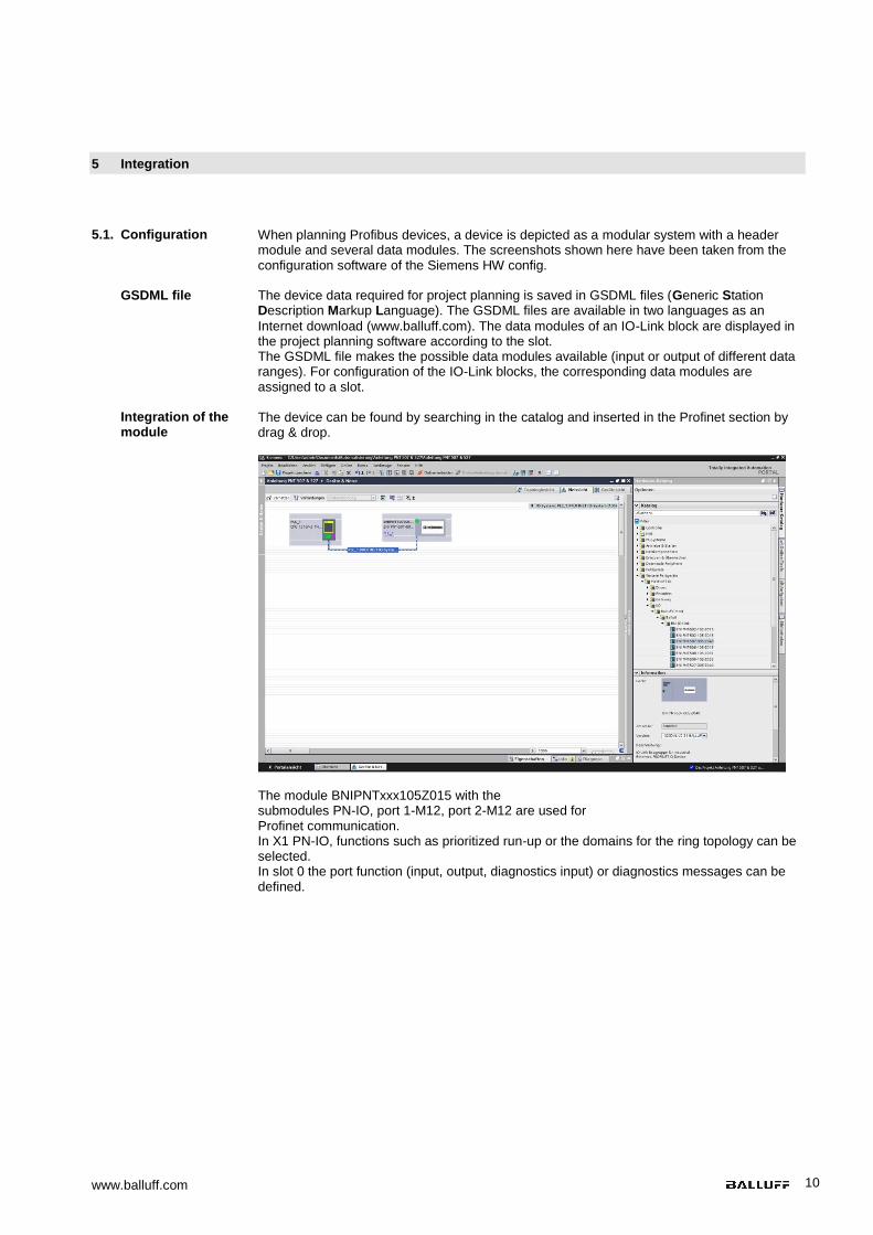
Integration of the module
The device can be found by searching in the catalog and inserted in the Profinet section by drag & drop.
The module BNIPNTxxx105Z015 with the submodules PN-IO, port 1-M12, port 2-M12 are used for Profinet communication. In X1 PN-IO, functions such as prioritized run-up or the domains for the ring topology can be selected. In slot 0 the port function (input, output, diagnostics input) or diagnostics messages can be defined.

Balluff Network Interface Profinet
www.balluff.com 11
5 Integration
Configuration of the header module
Double-click on the header module to open its properties. Click on the "Parameter" tab to open a menu selection for defining the port functions and diagnostic functions.
Note Standard input and output:
For each port, the function (N.C., N.O., diagnostic input (pin 2)) can be arbitrarily selected for each port at pin 2 and pin 4.
www.balluff.com 12
5 Integration
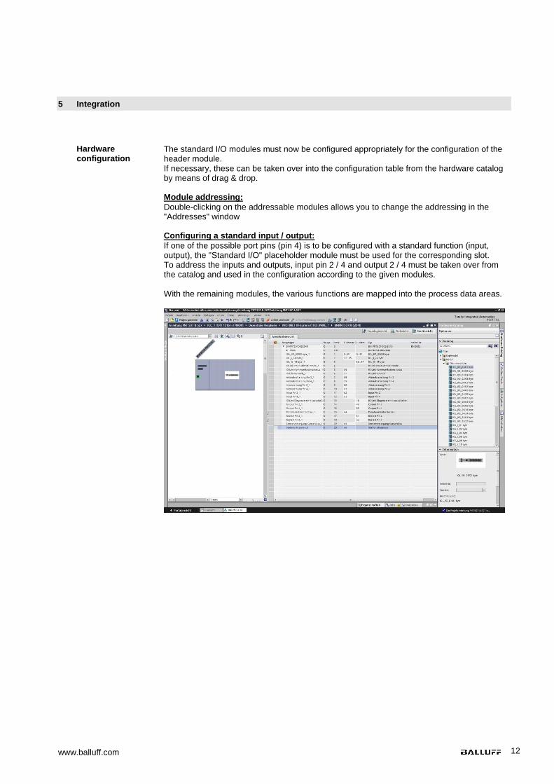
Hardware configuration
The standard I/O modules must now be configured appropriately for the configuration of the header module. If necessary, these can be taken over into the configuration table from the hardware catalog by means of drag & drop. Module addressing:
Double-clicking on the addressable modules allows you to change the addressing in the "Addresses" window Configuring a standard input / output:
If one of the possible port pins (pin 4) is to be configured with a standard function (input, output), the "Standard I/O" placeholder module must be used for the corresponding slot. To address the inputs and outputs, input pin 2 / 4 and output 2 / 4 must be taken over from the catalog and used in the configuration according to the given modules. With the remaining modules, the various functions are mapped into the process data areas.
Balluff Network Interface Profinet
www.balluff.com 13
5 Integration
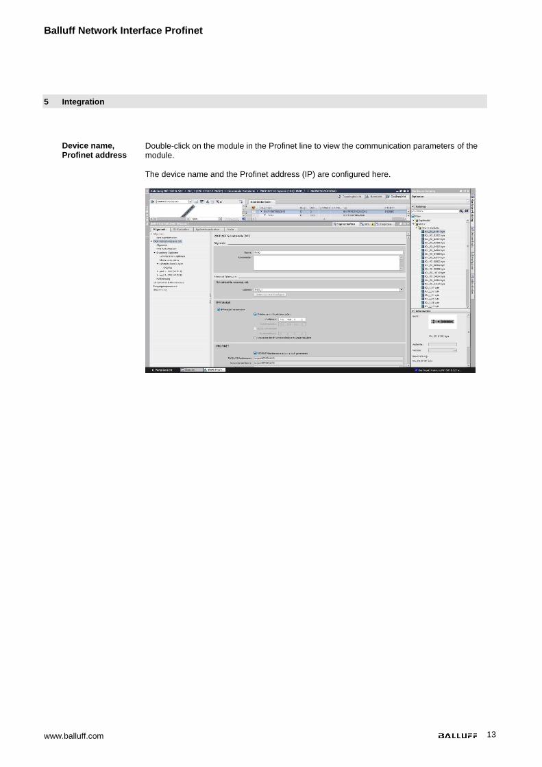
Device name, Profinet address
Double-click on the module in the Profinet line to view the communication parameters of the module. The device name and the Profinet address (IP) are configured here.
www.balluff.com 14
5 Integration
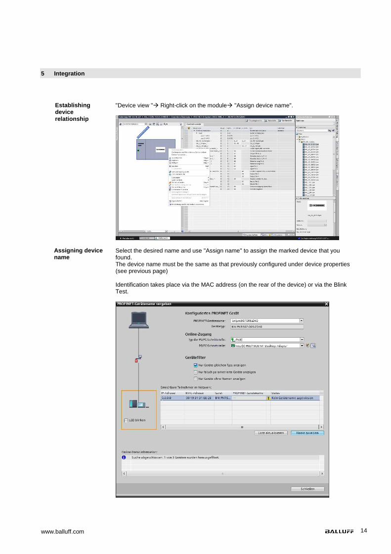
Establishing device relationship
"Device view " Right-click on the module "Assign device name".
Assigning device name
Select the desired name and use "Assign name" to assign the marked device that you found. The device name must be the same as that previously configured under device properties (see previous page) Identification takes place via the MAC address (on the rear of the device) or via the Blink Test.
Balluff Network Interface Profinet
www.balluff.com 15
5 Integration
Concluding the configuration
Download the configuration into HW config. At this point, the bus error on the module should disappear. If the module still reports a bus error, there could be a problem in one of the following areas:
- Device relationship not established. Scan the network and check whether the device is signaling under the correct device name and correct IP address. Adapt the Ethernet address or device name if necessary, assign the device name to the device once again and download the configuration.
Module settings Port functions Safe state
Global diagnostics: This function can be used to permit / suppress all diagnostics messages of the module. (optical diagnostics signals and diagnostics in configured diagnostics modules are not affected) Sensor supply undervoltage: This function can be used to permit / suppress the diagnostics message Sensor supply undervoltage. (optical diagnostics and diagnostics in configured diagnostics modules are not affected) Actuator supply undervoltage: This function can be used to permit / suppress the diagnostics message Actuator supply undervoltage. (optical diagnostics signals and diagnostics in configured diagnostics modules are not affected) Sensor connection to output: This function can be used to permit / suppress the diagnostics message Sensor Short-circuit on the module output. (Visual diagnostics and diagnostics in configured diagnostics modules is not affected) Function applies only to channels/pins which are configured as outputs. Channels/pins configured as inputs are unaffected. The function for every individual port pin can be defined here: Make contact = input as normally open contact Break contact = input as normally closed contact Output = output function This function is a supplement to an output configuration of the respective port pin. For each port pin, a safe status can be predefined which is assumed in the event of a failure in bus communication.
5.2. Functions in module properties
Description of the functions in module properties
www.balluff.com 16
5 Integration
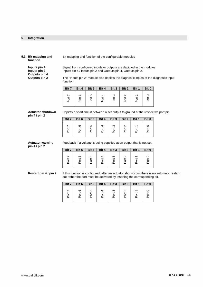
Inputs pin 4 Inputs pin 2 Outputs pin 4 Outputs pin 2
Signal from configured inputs or outputs are depicted in the modules Inputs pin 4 / Inputs pin 2 and Outputs pin 4, Outputs pin 2. The "Inputs pin 2" module also depicts the diagnostic inputs of the diagnostic input function.
Bit 7 Bit 6 Bit 5 Bit 4 Bit 3 Bit 2 Bit 1 Bit 0
Po
rt 7
Po
rt 6
Po
rt 5
Po
rt 4
Po
rt 3
Po
rt 2
Po
rt 1
Po
rt 0
Actuator shutdown pin 4 / pin 2
Depicts a short circuit between a set output to ground at the respective port pin.
Bit 7 Bit 6 Bit 5 Bit 4 Bit 3 Bit 2 Bit 1 Bit 0
Po
rt 7
Po
rt 6
Po
rt 5
Po
rt 4
Po
rt 3
Po
rt 2
Po
rt 1
Po
rt 0
Actuator warning pin 4 / pin 2
Feedback if a voltage is being supplied at an output that is not set.
Bit 7 Bit 6 Bit 5 Bit 4 Bit 3 Bit 2 Bit 1 Bit 0
Po
rt 7
Po
rt 6
Po
rt 5
Po
rt 4
Po
rt 3
Po
rt 2
Po
rt 1
Po
rt 0
Restart pin 4 / pin 2
If this function is configured, after an actuator short-circuit there is no automatic restart, but rather the port must be activated by inserting the corresponding bit.
Bit 7 Bit 6 Bit 5 Bit 4 Bit 3 Bit 2 Bit 1 Bit 0
Po
rt 7
Po
rt 6
Po
rt 5
Po
rt 4
Po
rt 3
Po
rt 2
Po
rt 1
Po
rt 0
5.3. Bit mapping and function
Bit mapping and function of the configurable modules
Balluff Network Interface Profinet
www.balluff.com 17
5 Integration
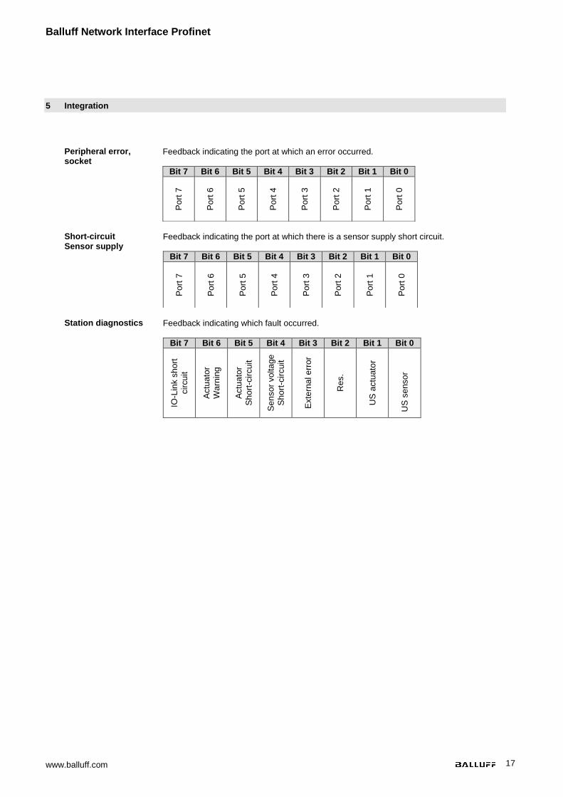
Peripheral error, socket
Feedback indicating the port at which an error occurred.
Bit 7 Bit 6 Bit 5 Bit 4 Bit 3 Bit 2 Bit 1 Bit 0 P
ort
7
Po
rt 6
Po
rt 5
Po
rt 4
Po
rt 3
Po
rt 2
Po
rt 1
Po
rt 0
Short-circuit Sensor supply
Feedback indicating the port at which there is a sensor supply short circuit.
Bit 7 Bit 6 Bit 5 Bit 4 Bit 3 Bit 2 Bit 1 Bit 0
Po
rt 7
Po
rt 6
Po
rt 5
Po
rt 4
Po
rt 3
Po
rt 2
Po
rt 1
Po
rt 0
Station diagnostics Feedback indicating which fault occurred.
Bit 7 Bit 6 Bit 5 Bit 4 Bit 3 Bit 2 Bit 1 Bit 0
IO-L
ink s
ho
rt
cir
cu
it
Actu
ato
r
Wa
rnin
g
Actu
ato
r
Sh
ort
-cir
cuit
Se
nso
r volta
ge
Sh
ort
-cir
cuit
Exte
rna
l e
rro
r
Res.
US
actu
ato
r
US
se
nso
r
www.balluff.com 18
6 Diagnostics
6.1. Diagnostics message
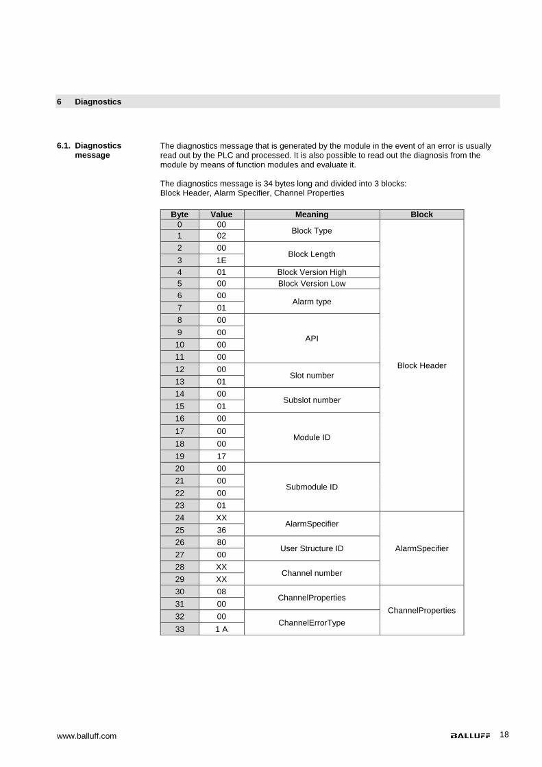
The diagnostics message that is generated by the module in the event of an error is usually read out by the PLC and processed. It is also possible to read out the diagnosis from the module by means of function modules and evaluate it. The diagnostics message is 34 bytes long and divided into 3 blocks: Block Header, Alarm Specifier, Channel Properties
Byte Value Meaning Block
0 00 Block Type
Block Header
1 02
2 00 Block Length
3 1E
4 01 Block Version High
5 00 Block Version Low
6 00 Alarm type
7 01
8 00
API 9 00
10 00
11 00
12 00 Slot number
13 01
14 00 Subslot number
15 01
16 00
Module ID 17 00
18 00
19 17
20 00
Submodule ID 21 00
22 00
23 01
24 XX AlarmSpecifier
AlarmSpecifier
25 36
26 80 User Structure ID
27 00
28 XX Channel number
29 XX
30 08 ChannelProperties
ChannelProperties 31 00
32 00 ChannelErrorType
33 1 A
Balluff Network Interface Profinet
www.balluff.com 19
6 Diagnostics
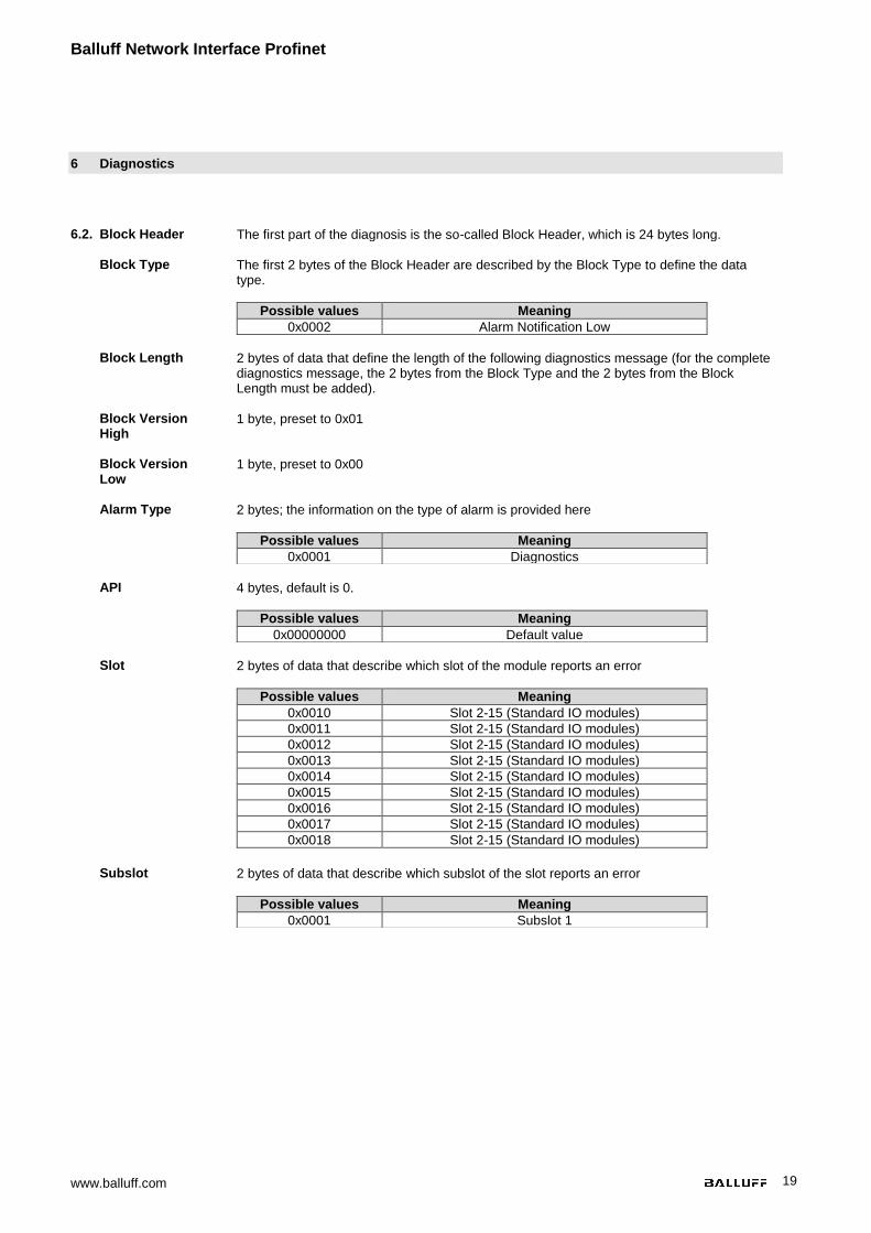
6.2. Block Header The first part of the diagnosis is the so-called Block Header, which is 24 bytes long.
Block Type The first 2 bytes of the Block Header are described by the Block Type to define the data type.
Possible values Meaning
0x0002 Alarm Notification Low
Block Length 2 bytes of data that define the length of the following diagnostics message (for the complete
diagnostics message, the 2 bytes from the Block Type and the 2 bytes from the Block Length must be added).
Block Version High
1 byte, preset to 0x01
Block Version Low
1 byte, preset to 0x00
Alarm Type 2 bytes; the information on the type of alarm is provided here
Possible values Meaning
0x0001 Diagnostics
API 4 bytes, default is 0.
Possible values Meaning
0x00000000 Default value
Slot 2 bytes of data that describe which slot of the module reports an error
Possible values Meaning
0x0010 Slot 2-15 (Standard IO modules)
0x0011 Slot 2-15 (Standard IO modules)
0x0012 Slot 2-15 (Standard IO modules)
0x0013 Slot 2-15 (Standard IO modules)
0x0014 Slot 2-15 (Standard IO modules)
0x0015 Slot 2-15 (Standard IO modules)
0x0016 Slot 2-15 (Standard IO modules)
0x0017 Slot 2-15 (Standard IO modules)
0x0018 Slot 2-15 (Standard IO modules)
Subslot 2 bytes of data that describe which subslot of the slot reports an error
Possible values Meaning
0x0001 Subslot 1
www.balluff.com 20
6 Diagnostics
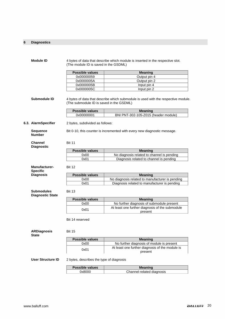
Module ID 4 bytes of data that describe which module is inserted in the respective slot. (The module ID is saved in the GSDML)
Possible values Meaning
0x00000059 Output pin 4
0x0000005A Output pin 2
0x0000005B Input pin 4
0x0000005C Input pin 2
Submodule ID 4 bytes of data that describe which submodule is used with the respective module.
(The submodule ID is saved in the GSDML)
Possible values Meaning
0x00000001 BNI PNT-302-105-Z015 (header module)
6.3. AlarmSpecifier 2 bytes, subdivided as follows:
Sequence Number
Bit 0-10, this counter is incremented with every new diagnostic message.
Channel Diagnostic
Bit 11
Possible values Meaning
0x00 No diagnosis related to channel is pending
0x01 Diagnosis related to channel is pending
Manufacturer-Specific Diagnosis
Bit 12
Possible values Meaning
0x00 No diagnosis related to manufacturer is pending
0x01 Diagnosis related to manufacturer is pending
Submodules Diagnostic State
Bit 13
Possible values Meaning
0x00 No further diagnosis of submodule present
0x01 At least one further diagnosis of the submodule
present
Bit 14 reserved
ARDiagnosis State
Bit 15
Possible values Meaning
0x00 No further diagnosis of module is present
0x01 At least one further diagnosis of the module is
present
User Structure ID 2 bytes, describes the type of diagnosis
Possible values Meaning
0x8000 Channel-related diagnosis
Balluff Network Interface Profinet
www.balluff.com 21
6 Diagnostics
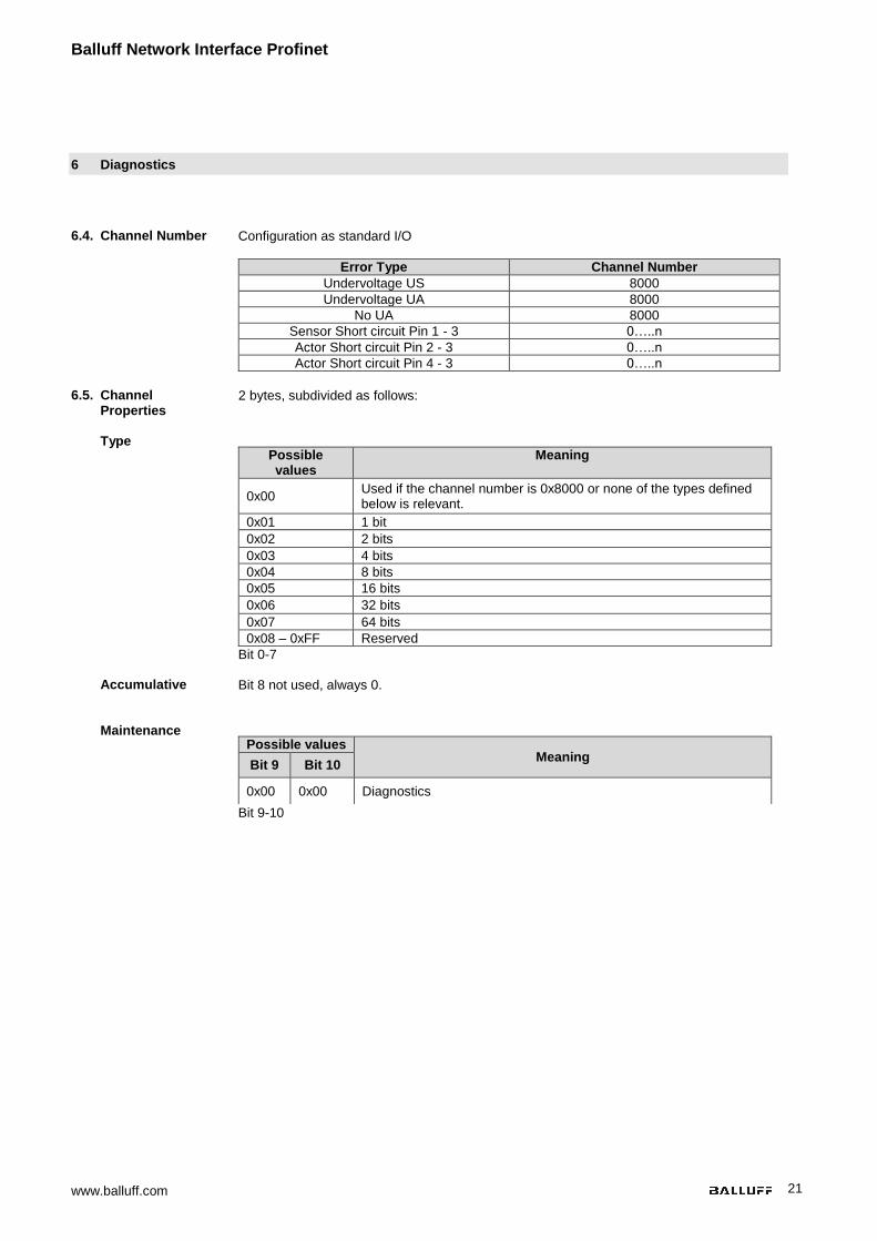
6.4. Channel Number Configuration as standard I/O
Error Type Channel Number
Undervoltage US 8000
Undervoltage UA 8000
No UA 8000
Sensor Short circuit Pin 1 - 3 0…..n
Actor Short circuit Pin 2 - 3 0…..n
Actor Short circuit Pin 4 - 3 0…..n
6.5. Channel
Properties 2 bytes, subdivided as follows:
Type
Bit 0-7
Possible values
Meaning
0x00 Used if the channel number is 0x8000 or none of the types defined below is relevant.
0x01 1 bit
0x02 2 bits
0x03 4 bits
0x04 8 bits
0x05 16 bits
0x06 32 bits
0x07 64 bits
0x08 – 0xFF Reserved
Accumulative Bit 8 not used, always 0.
Maintenance
Bit 9-10
Possible values Meaning
Bit 9 Bit 10
0x00 0x00 Diagnostics
www.balluff.com 22
6 Diagnostics
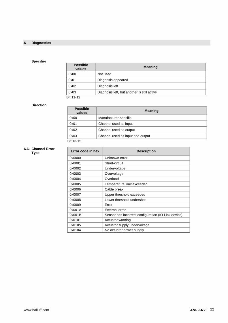
Specifier
Bit 11-12
Possible values
Meaning
0x00 Not used
0x01 Diagnosis appeared
0x02 Diagnosis left
0x03 Diagnosis left, but another is still active
Direction
Bit 13-15
Possible values
Meaning
0x00 Manufacturer-specific
0x01 Channel used as input
0x02 Channel used as output
0x03 Channel used as input and output
6.6. Channel Error
Type
Error code in hex Description
0x0000 Unknown error
0x0001 Short-circuit
0x0002 Undervoltage
0x0003 Overvoltage
0x0004 Overload
0x0005 Temperature limit exceeded
0x0006 Cable break
0x0007 Upper threshold exceeded
0x0008 Lower threshold undershot
0x0009 Error
0x001A External error
0x001B Sensor has incorrect configuration (IO-Link device)
0x0101 Actuator warning
0x0105 Actuator supply undervoltage
0x0104 No actuator power supply
Balluff Network Interface Profinet
www.balluff.com 23
7 Webserver
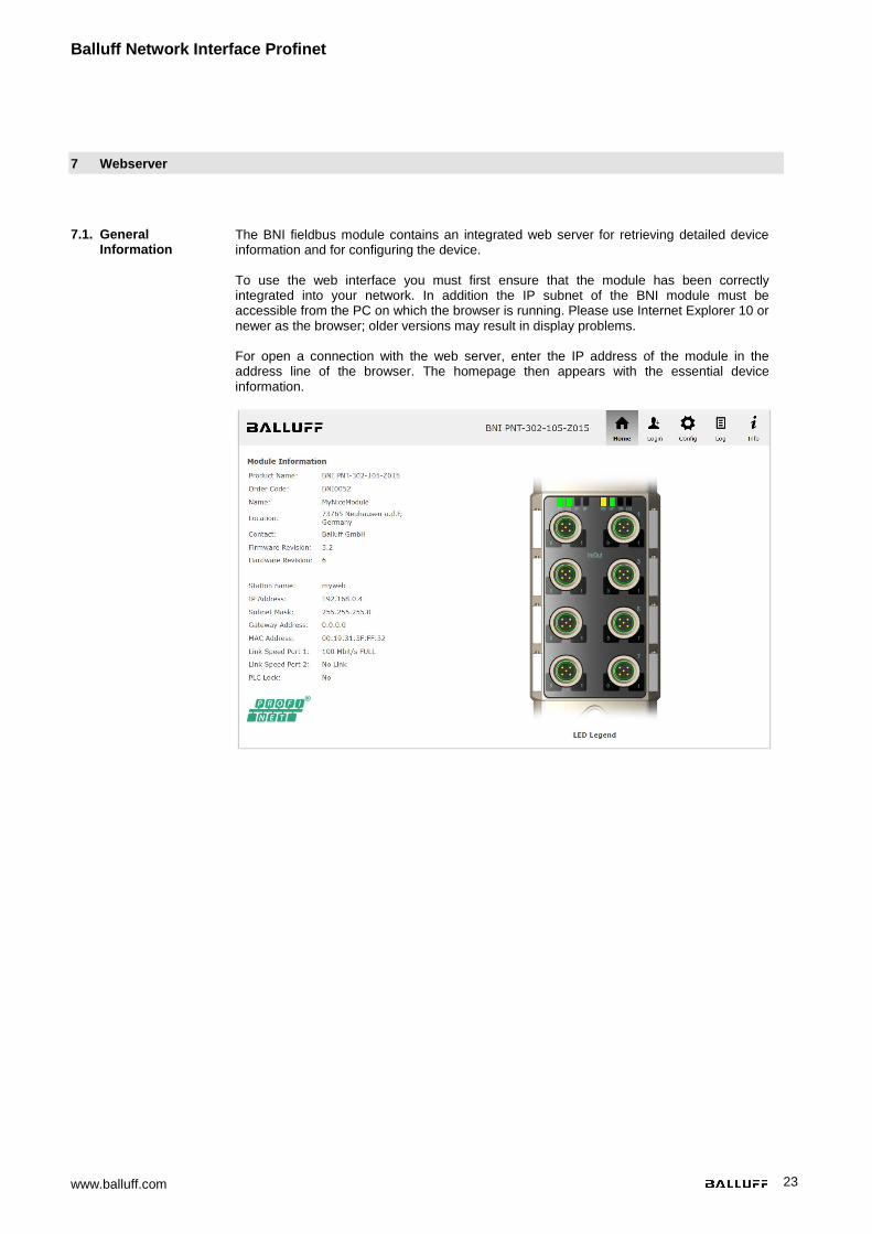
7.1. General Information
The BNI fieldbus module contains an integrated web server for retrieving detailed device information and for configuring the device. To use the web interface you must first ensure that the module has been correctly integrated into your network. In addition the IP subnet of the BNI module must be accessible from the PC on which the browser is running. Please use Internet Explorer 10 or newer as the browser; older versions may result in display problems. For open a connection with the web server, enter the IP address of the module in the address line of the browser. The homepage then appears with the essential device information.

www.balluff.com 24
7 Webserver
7.2. Navigation / Info The navigation bar is located in the upper area of the window, which allows you to switch between the various dialogs of the web interface. To do this click on the corresponding icon. When the "Info" tab is selected the following overview appears:
The "BALLUFF" logo at upper right links to the international Balluff homepage.
Balluff Network Interface Profinet
www.balluff.com 25
7 Webserver
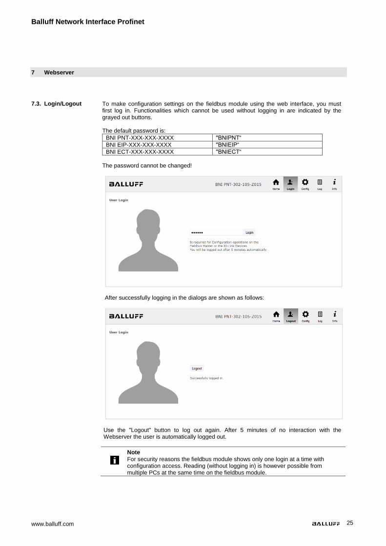
7.3. Login/Logout To make configuration settings on the fieldbus module using the web interface, you must first log in. Functionalities which cannot be used without logging in are indicated by the grayed out buttons. The default password is:
BNI PNT-XXX-XXX-XXXX "BNIPNT“
BNI EIP-XXX-XXX-XXXX "BNIEIP“
BNI ECT-XXX-XXX-XXXX "BNIECT“
The password cannot be changed!
After successfully logging in the dialogs are shown as follows:
Use the "Logout" button to log out again. After 5 minutes of no interaction with the
Webserver the user is automatically logged out.
Note
For security reasons the fieldbus module shows only one login at a time with configuration access. Reading (without logging in) is however possible from multiple PCs at the same time on the fieldbus module.
www.balluff.com 26
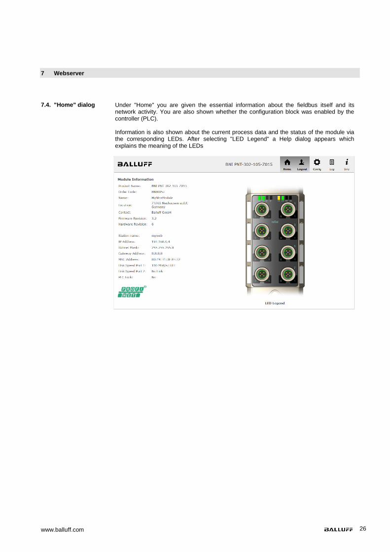
7 Webserver
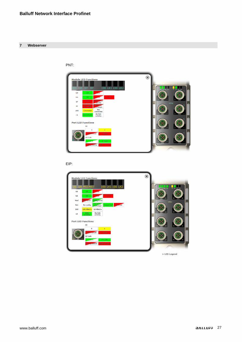
7.4. "Home" dialog Under "Home" you are given the essential information about the fieldbus itself and its network activity. You are also shown whether the configuration block was enabled by the controller (PLC). Information is also shown about the current process data and the status of the module via the corresponding LEDs. After selecting "LED Legend" a Help dialog appears which explains the meaning of the LEDs
Balluff Network Interface Profinet
www.balluff.com 27
7 Webserver
PNT:
EIP:

www.balluff.com 28
7 Webserver
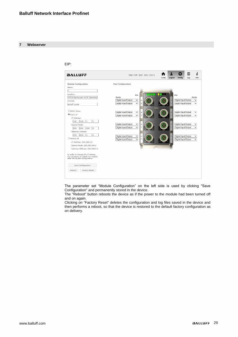
7.5. "Config" dialog The configuration page enables configuration of the module. You can change the module information texts and the (for EIP) IP-Configuration.
PNT / ECT:
Balluff Network Interface Profinet
www.balluff.com 29
7 Webserver
EIP:
The parameter set “Module Configuration” on the left side is used by clicking "Save Configuration" and permanently stored in the device. The "Reboot" button reboots the device as if the power to the module had been turned off and on again. Clicking on "Factory Reset" deletes the configuration and log files saved in the device and then performs a reboot, so that the device is restored to the default factory configuration as on delivery.
www.balluff.com 30
7 Webserver
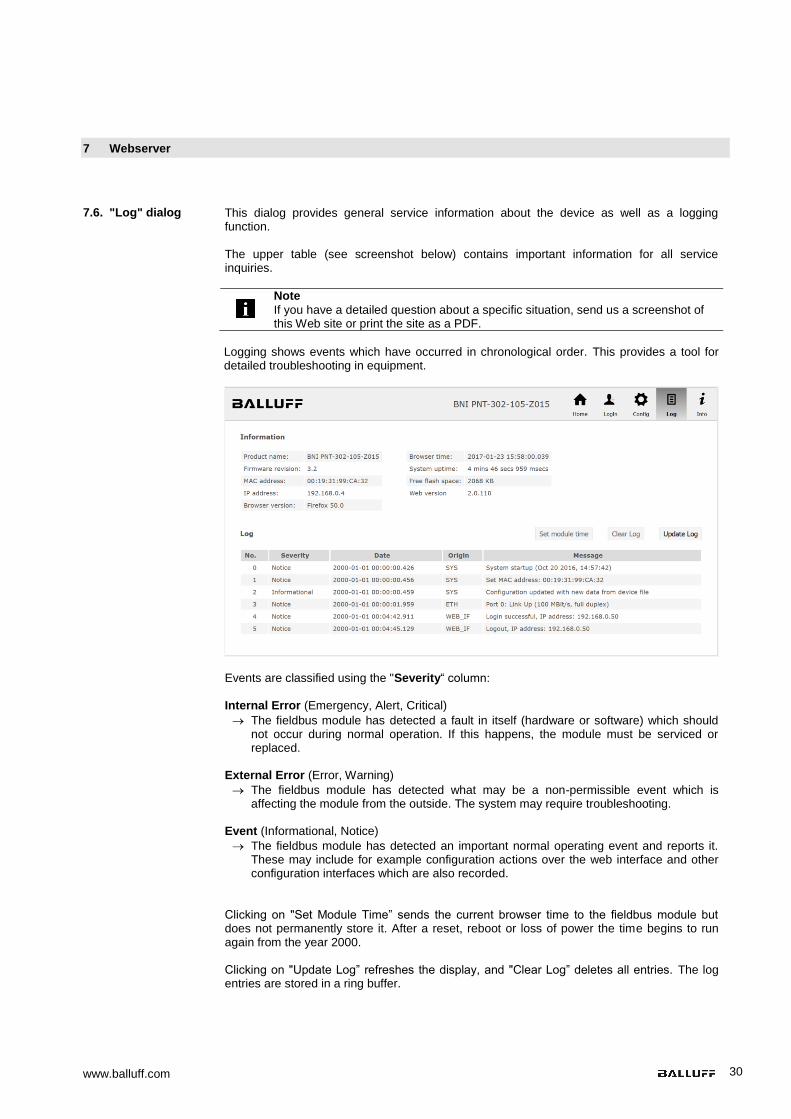
7.6. "Log" dialog This dialog provides general service information about the device as well as a logging function. The upper table (see screenshot below) contains important information for all service inquiries.
Note
If you have a detailed question about a specific situation, send us a screenshot of this Web site or print the site as a PDF.
Logging shows events which have occurred in chronological order. This provides a tool for
detailed troubleshooting in equipment.
Events are classified using the "Severity“ column:
Internal Error (Emergency, Alert, Critical)
The fieldbus module has detected a fault in itself (hardware or software) which should not occur during normal operation. If this happens, the module must be serviced or replaced.
External Error (Error, Warning)
The fieldbus module has detected what may be a non-permissible event which is affecting the module from the outside. The system may require troubleshooting.
Event (Informational, Notice)
The fieldbus module has detected an important normal operating event and reports it. These may include for example configuration actions over the web interface and other configuration interfaces which are also recorded.
Clicking on "Set Module Time” sends the current browser time to the fieldbus module but does not permanently store it. After a reset, reboot or loss of power the time begins to run again from the year 2000. Clicking on "Update Log” refreshes the display, and "Clear Log” deletes all entries. The log entries are stored in a ring buffer.
Balluff Network Interface Profinet
www.balluff.com 31
8 Monitoring & Diagnostics
8.1. General The fieldbus module offers a number of diagnostics interfaces which are described in the following:
Device diagnostics using the web interface
Network diagnostics via SNMP
Fieldbus-specific diagnostics using the PLC The web interface and the fieldbus-specific diagnostics interface are each described in a separate section. The monitoring and diagnostics interfaces on the device are accessed via the IP-based management interface over the Ethernet network. Alternately to the procedure for setting IP access described in the "Integration" section, other dedicated configuration tools can also be used together with the DCP protocol of PROFINET. The following parameters must then be set:
IP address (IP)
Subnet mask (SN)
Gateway address (GW)
Device name The configuration settings can be reset to their factory defaults through the web interface. Configuration settings are only possible if the module has no active connection with a controller unit.
8.2. SNMP MIBs Monitoring and diagnostics of the device network settings can be done over the network
using the SNMPv1 protocol. This can be accessed simply from a so-called SNMP browser or common network management applications. The following MIBs are supported:
MIB-2 (RFC 1213)
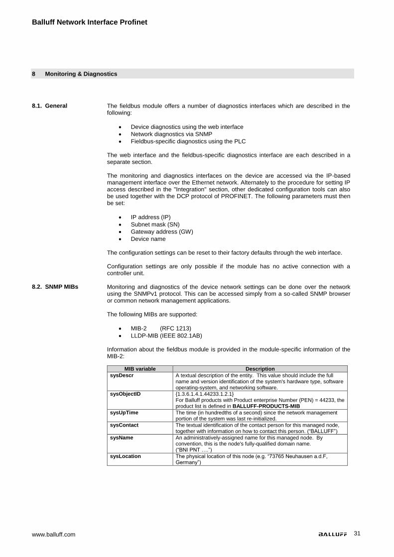
LLDP-MIB (IEEE 802.1AB) Information about the fieldbus module is provided in the module-specific information of the MIB-2:
MIB variable Description
sysDescr A textual description of the entity. This value should include the full name and version identification of the system's hardware type, software operating-system, and networking software.
sysObjectID {1.3.6.1.4.1.44233.1.2.1} For Balluff products with Product enterprise Number (PEN) = 44233, the product list is defined in BALLUFF-PRODUCTS-MIB
sysUpTime The time (in hundredths of a second) since the network management portion of the system was last re-initialized.
sysContact The textual identification of the contact person for this managed node, together with information on how to contact this person. (“BALLUFF”)
sysName An administratively-assigned name for this managed node. By convention, this is the node's fully-qualified domain name. (“BNI PNT ….”)
sysLocation The physical location of this node (e.g. “73765 Neuhausen a.d.F, Germany”)
www.balluff.com 32
8 Monitoring & Diagnostics
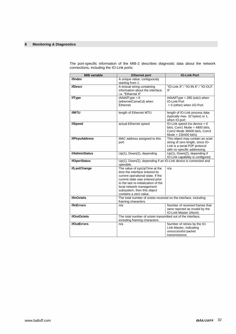
The port-specific information of the MIB-2 describes diagnostic data about the network connections, including the IO-Link ports:
MIB variable Ethernet port IO-Link Port
ifIndex A unique value, contiguously starting from 1.
ifDescr A textual string containing information about the interface, i.e. "Ethernet X”
”IO-Link X" / “IO-IN X” / ”IO-OUT X”
ifType IANAifType = 6 (ethernetCsmaCd) when Ethernet
IANAifType = 280 (sdci) when IO-Link-Port = 0 (other) when I/O-Port
ifMTU length of Ethernet MTU length of IO-Link process data (typically max. 32 bytes) or 1, when IO-port
ifSpeed actual Ethernet speed IO-Link speed (no device = 0 bit/s, Com1 Mode = 4800 bit/s, Com2 Mode 38400 bit/s, Com3 Mode = 230400 bit/s)
ifPhysAddress MAC address assigned to this port
This object may contain an octet string of zero length, since IO-Link is a serial P2P protocol with no specific addressing.
ifAdminStatus Up(1), Down(2), depending Up(1), Down(2), depending if IO-Link capability is configured.
ifOperStatus Up(1), Down(2), depending if an IO-Link device is connected and operable.
ifLastChange The value of sysUpTime at the time the interface entered its current operational state. If the current state was entered prior to the last re-initialization of the local network management subsystem, then this object contains a zero value.
n/a
ifInOctets The total number of octets received on the interface, including framing characters.
ifInErrors n/a Number of received frames that were rejected as invalid by the IO-Link-Master (Abort).
ifOutOctets The total number of octets transmitted out of the interface, including framing characters.
ifOutErrors n/a Number of retries by the IO-Link-Master, indicating unsuccessful packet transmissions.
Balluff Network Interface Profinet
www.balluff.com 33
9 Appendix
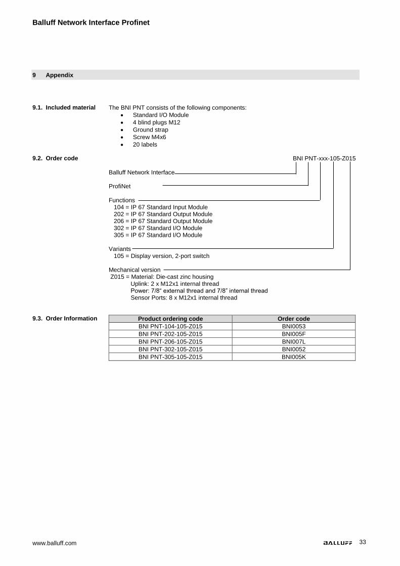
9.1. Included material The BNI PNT consists of the following components:
Standard I/O Module
4 blind plugs M12
Ground strap
Screw M4x6
20 labels 9.2. Order code BNI PNT-xxx-105-Z015
Balluff Network Interface ProfiNet Functions 104 = IP 67 Standard Input Module 202 = IP 67 Standard Output Module 206 = IP 67 Standard Output Module 302 = IP 67 Standard I/O Module 305 = IP 67 Standard I/O Module Variants 105 = Display version, 2-port switch Mechanical version Z015 = Material: Die-cast zinc housing Uplink: 2 x M12x1 internal thread Power: 7/8“ external thread and 7/8” internal thread Sensor Ports: 8 x M12x1 internal thread
9.3. Order Information Product ordering code Order code
BNI PNT-104-105-Z015 BNI0053
BNI PNT-202-105-Z015 BNI005F
BNI PNT-206-105-Z015 BNI007L
BNI PNT-302-105-Z015 BNI0052
BNI PNT-305-105-Z015 BNI005K

www.balluff.com 34
Notes

www.balluff.com
www.balluff.com
Balluff GmbH Schurwaldstrasse 9 73765 Neuhausen a.d.F. Germany Tel. +49 7158 173-0 Fax +49 7158 5010 [email protected]
Nr.
88
616
0-7
26
E
03
.12
486
3
Ed
itio
n I1
7
Repla
ce
s E
ditio
n 1
401
S
ub
ject to
mo
dific
ation