Embed Size (px)
Citation preview
U S E R ’ S G U I D E
V E R S I O N 1 . 4 . 3
FORMULA
8200
™
Fast Ethernet Workgroup Switch
PN 613-10611-00 Rev. A
ATMEthernet Fast Ethernet
Fiber
Copyright © 1998 Allied Telesyn International, Corp.All rights reserved. No part of this publication may be reproduced without prior written permission from Allied Telesyn International, Corp.
FORMULA 8200 is a trademark of Allied Telesyn International, Corp.
Ethernet is a registered trademark of Xerox Corporation. SNMPc is a registered trademark of Castle Rock. UNIX is a registered trademark of X/Open Company, LTD. Windows 95 and Windows NT are registered trademarks of Microsoft Corporation. All other product names, company names, logos or other designations mentioned herein are trademarks or registered trademarks of their respective owners.
Allied Telesyn International, Corp. reserves the right to make changes in specifications and other information contained in this document without prior written notice. The information provided herein is subject to change without notice. In no event shall Allied Telesyn International, Corp. be liable for any incidental, special, indirect, or consequential damages whatsoever, including but not limited to lost profits, arising out of or related to this manual or the information contained herein, even if Allied Telesyn International, Corp. has been advised of, known, or should have known, the possibility of such damages.
Table of Contents
Preface ...................................................................................................................................................................viiWho Should Use This Guide ............................................................................................................................................................................viiiHow This Guide Is Organized ............................................................................................................................................................................ ixDocument Conventions Used in This Guide ................................................................................................................................................ xRelated Documents .............................................................................................................................................................................................. xiRecommended Reading .................................................................................................................................................................................... xiiAllied Telesyn’s Software Library ................................................................................................................................................................... xiii
Chapter 1Overview ..............................................................................................................................................................1-1Product Features ................................................................................................................................................................................................ 1-1
Chapter 2Accessing the Command Line Interface (CLI) ...............................................................................................2-1Connecting the Console .................................................................................................................................................................................. 2-2
Terminal Configuration ........................................................................................................................................................................... 2-2Viewing Terminal Configuration Using the CLI .............................................................................................................................. 2-2
Observing the Power-On Self Test ............................................................................................................................................................... 2-3Observing the LEDs .................................................................................................................................................................................. 2-4
Logging In ............................................................................................................................................................................................................. 2-6Logging In Without a Password ........................................................................................................................................................... 2-7
Entering Commands ......................................................................................................................................................................................... 2-8Use of Square Brackets [ ] ....................................................................................................................................................................... 2-8Use of Angle Brackets <> ....................................................................................................................................................................... 2-8The LOOKUP Command .......................................................................................................................................................................... 2-9Command Formats ................................................................................................................................................................................... 2-9Moving Through the Menus ................................................................................................................................................................2-10
Configuring IP Information ...........................................................................................................................................................................2-11Verifying Firmware Information .................................................................................................................................................................2-13
Updating Your Ethernet Ports ............................................................................................................................................................2-13Updating System Information ............................................................................................................................................................2-13
Using Telnet to Access the Switch .............................................................................................................................................................2-14Resetting and Rebooting the Switch ........................................................................................................................................................2-15Where to Go Next .............................................................................................................................................................................................2-15
iii
Table of Contents
Chapter 3Configuring the FORMULA 8200 Switch ......................................................................................................... 3-1Default Configurations .....................................................................................................................................................................................3-1Optimizing Functionality for Your Application .......................................................................................................................................3-2Virtual LANs ..........................................................................................................................................................................................................3-2
FORMULA 8200 Implementation of VLANs ......................................................................................................................................3-3Virtual Bridges, Virtual Interfaces, Virtual Routers .........................................................................................................................3-5Spanning Tree .............................................................................................................................................................................................3-6
Configuring a Virtual LAN (VLAN) .................................................................................................................................................................3-8Configuring a Virtual Bridge ........................................................................................................................................................................ 3-11
Chapter 4Operating and Managing the FORMULA 8200 Switch .................................................................................. 4-1Using Online Help ..............................................................................................................................................................................................4-2Displaying the System Configuration .........................................................................................................................................................4-2Displaying Console Port Parameters ...........................................................................................................................................................4-4Displaying Ethernet Port Settings Information .......................................................................................................................................4-5Configuring Ethernet Port Settings .............................................................................................................................................................4-6Configuring Ethernet Port Statistics ............................................................................................................................................................4-7Displaying Ethernet Port Statistics Information ......................................................................................................................................4-8Clearing a Port’s Statistics Counters ............................................................................................................................................................4-9Using Ethernet Port Mirroring .......................................................................................................................................................................4-9Displaying Virtual LAN (VLAN) Information ........................................................................................................................................... 4-12Displaying Virtual Router Information ..................................................................................................................................................... 4-13Displaying Virtual Port Information .......................................................................................................................................................... 4-14Displaying Virtual Port Statistics ................................................................................................................................................................ 4-15Displaying Virtual Bridge Information ..................................................................................................................................................... 4-16Displaying Spanning Tree Port Parameters ........................................................................................................................................... 4-17Displaying the Bridge Forwarding Table ................................................................................................................................................ 4-18Upgrading Firmware ...................................................................................................................................................................................... 4-19
Backing Up Your Current Configurations ...................................................................................................................................... 4-20Configuring for the Download Process .......................................................................................................................................... 4-21Downloading the Firmware ................................................................................................................................................................ 4-22Restoring Your Configurations .......................................................................................................................................................... 4-24In Case of Problems With the Software Upgrade ........................................................................................................................ 4-25
Displaying RIP Support Information ......................................................................................................................................................... 4-26Modifying the IP RIP Mode ........................................................................................................................................................................... 4-27Configuring Static Routes ............................................................................................................................................................................ 4-28
Deleting Static Routes ........................................................................................................................................................................... 4-28Removing an IP Default Gateway .............................................................................................................................................................. 4-29Configuring SNMP Parameters ................................................................................................................................................................... 4-30Displaying SNMP Parameters ...................................................................................................................................................................... 4-31
iv
FORMULA 8200 User’s Guide
Chapter 5Command Reference ..........................................................................................................................................5-1ATM and FDDI Support .................................................................................................................................................................................... 5-5Command Edit Mode ........................................................................................................................................................................................ 5-6
Edit Mode Commands ............................................................................................................................................................................. 5-6Command Descriptions .......................................................................................................................................................................... 5-6
ALIAS Command ................................................................................................................................................................................................ 5-7ALLCMD Command ........................................................................................................................................................................................... 5-8ATM Command ................................................................................................................................................................................................... 5-9BOOT Command ..............................................................................................................................................................................................5-10CONSOLE Command ......................................................................................................................................................................................5-12ELOG Command ...............................................................................................................................................................................................5-14ETHERNET Command .....................................................................................................................................................................................5-17EXIT Command .................................................................................................................................................................................................5-24FILE Command ..................................................................................................................................................................................................5-25INET Command .................................................................................................................................................................................................5-27LOOKUP Command .........................................................................................................................................................................................5-30MODE Command .............................................................................................................................................................................................5-31PORTSERV Command .....................................................................................................................................................................................5-33REBOOT Command .........................................................................................................................................................................................5-34SNMP Command ..............................................................................................................................................................................................5-35SYSTEM Command ..........................................................................................................................................................................................5-38TFTP Command ................................................................................................................................................................................................5-39TOP Command ..................................................................................................................................................................................................5-40UP Command ....................................................................................................................................................................................................5-41VBRIDGE Command ........................................................................................................................................................................................5-42VLAN Command ...............................................................................................................................................................................................5-51
Appendix ACommand Summary ......................................................................................................................................... A-1
Appendix BRMON Configuration ......................................................................................................................................... B-1MIB Support ......................................................................................................................................................................................................... B-2SNMP Management Using Castle Rock’s SNMPc“ .................................................................................................................................. B-3RMON Support .................................................................................................................................................................................................... B-5
Enabling RMON Objects ......................................................................................................................................................................... B-5Disabling RMON Objects ........................................................................................................................................................................ B-6
Appendix CDownloading Software at the [VxWorks] Prompt ........................................................................................ C-1Firmware Upgrade Using FTP/TFTP ............................................................................................................................................................C-2
Backing Up Your Current Configurations .........................................................................................................................................C-3Configuring for the TFTP Download Process ..................................................................................................................................C-4Downloading the Firmware Using FTP/TFTP ..................................................................................................................................C-5Restoring Your Configurations .............................................................................................................................................................C-9
Firmware Upgrade Using Zmodem .......................................................................................................................................................... C-10In Case of Problems With the Software Upgrade ................................................................................................................................ C-13
Index ............................................................................................................................................................INDEX-1
v

Preface
This guide includes information about configuring and operating Allied Telesyn International Corp.’s FORMULA 8200™ 10/100 Mbps Fast Ethernet Workgroup Switch with any of the following configurations:
❑ AT-8208 or AT-8216, the FORMULA 8200 switch with either 8 or 16 10/100 Mbps TX ports with firmware version 1.4.3 or later
❑ AT-8208F/SC or AT-8216F/SC, the FORMULA 8200 switch with either 8 or 16 100 Mbps FX ports with firmware version 1.4.3 or later
❑ Any of the above switch models with one of the following uplink cards:
— AT-8202 ATM uplink card
— AT-8203 FDDI uplink card
This guide assumes that a FORMULA 8200 switch has been installed and is operational. For more information on installing the switch, refer to the FORMULA 8200 Installation Guide.
vii
Preface
Who Should Use This Guide
This guide is designed for you, the network administrator, to help you configure, operate, and manage the FORMULA 8200 switch as a device on your local area network. It assumes that you understand some of the basic concepts of local area networks, including:
❑ Ethernet MAC addresses
❑ Collision domains
❑ Broadcast domains
❑ CSMA/CD
❑ Differences between repeaters, bridges, and routers
❑ Spanning Tree Protocol
❑ Virtual LANs (VLANs)
❑ TCP/IP and associated protocols and applications
For detailed information about any of the above topics, see Recommended Reading at the end of this Preface.
If you have any uplink card installed, you must be familiar with the ATM or FDDI technology.
viii
FORMULA 8200 User’s Guide
How This Guide Is Organized
This guide consists of the following sections:
Chapter 1, Overview, provides a product overview and a list of common features that apply to all switch models.
Chapter 2, Accessing the Command Line Interface (CLI), provides information on attaching a console port and accessing the command line interface (CLI) to enter basic configuration parameters.
Chapter 3, Configuring the FORMULA 8200 Switch, provides procedures to configure the FORMULA 8200.
Chapter 4, Operating and Managing the FORMULA 8200 Switch, provides procedures to monitor the FORMULA 8200 and perform routine management tasks using the CLI.
Chapter 5, Command Reference, includes a description of all the commands and provides examples on where to use these commands.
Appendix A, Command Summary, is a table that lists all FORMULA 8200 commands in alphabetical order, their corresponding aliases, and the purpose of each command.
Appendix B, RMON Configuration, provides a sample procedure to configure your SNMP management station to manage and monitor the FORMULA 8200 switch.
Appendix C, Downloading Software at the [VxWorks] Prompt, provides the alternative procedures to upgrade switch software if the switch CLI is not accessible.
The Index at the back of this guide is according to subject matter.
For a definition of terms commonly used in Allied Telesyn technical publications, refer to the website glossary at www.alliedtelesyn.com.
ix
Preface
Document Conventions Used in This Guide
This section describes the typographic conventions used in this guide.
NoteThe command line interface (CLI) portion of the FORMULA 8200 is not case sensitive; however, this manual shows commands in uppercase letters. You may type your commands in either uppercase or lowercase, as shown in some of the examples.
This guide uses the following symbols to highlight special messages:
NoteA note includes information of importance or special interest.
CautionA caution includes information that will help you prevent equipment failure or loss of data.
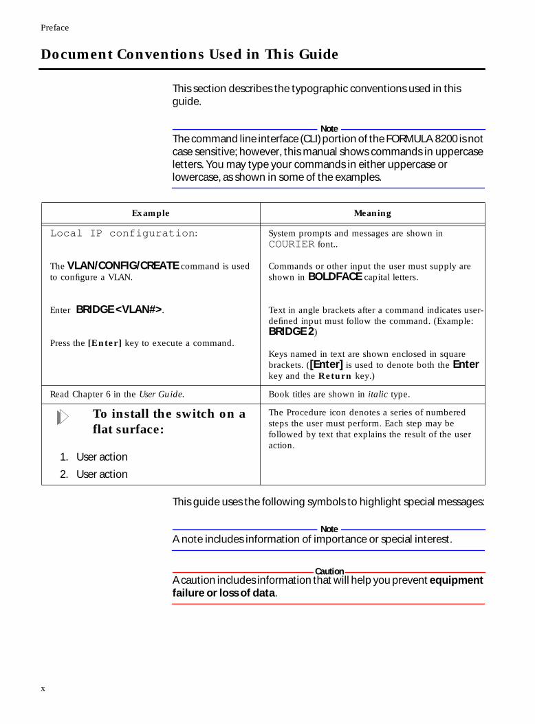
Example Meaning
Local IP configuration:
The VLAN/CONFIG/CREATE command is used to configure a VLAN.
Enter BRIDGE <VLAN#>.
Press the [Enter] key to execute a command.
System prompts and messages are shown in COURIER font..
Commands or other input the user must supply are shown in BOLDFACE capital letters.
Text in angle brackets after a command indicates user-defined input must follow the command. (Example: BRIDGE 2)
Keys named in text are shown enclosed in square brackets. ([Enter] is used to denote both the Enter key and the Return key.)
Read Chapter 6 in the User Guide. Book titles are shown in italic type.
To install the switch on a flat surface:
1. User action
2. User action
The Procedure icon denotes a series of numbered steps the user must perform. Each step may be followed by text that explains the result of the user action.
x
FORMULA 8200 User’s Guide
WarningA warning includes information that will help you prevent injury or equipment damage.
Related Documents
Refer to the following related publications from Allied Telesyn for additional information on the FORMULA 8200 switch:
❑ FORMULA 8200 Installation Guide for information on how to install and set up the switch
NoteThere are two versions of the FORMULA 8200 Installation Guide: one for 10Bse-T/100Base-TX ports and one for 100Base-FX ports.
❑ AT-8201 Installation Guide for information on how to install the eight-port 10/100Base-TX expansion module
❑ AT-8201 F/SC Installation Guide for information on how to install the eight-port 100Base-FX fiber expansion module
❑ AT-8202 and AT-8203 ATM and FDDI Uplink Installation Guide for information on how to install the ATM or FDDI uplink card and the accelerator card
❑ AT-8202 ATM Uplink User’s Guide for information about configuring and using the ATM uplink card
❑ AT-8203 FDDI Uplink User’s Guide for information about configuring and using the FDDI uplink card
❑ Release Notes that may be included in the package or distributed from Allied Telesyn’s website for the latest information about the product
These guides are available in PDF format from Allied Telesyn’s website at www.alliedtelesyn.com/manuals.htm.
xi
Preface
Recommended Reading
The following documents provide additional information on the topics described in this manual:
Interconnections: Bridges and Routers, Radia Perlman (1992).
Troubleshooting TCP/IP, Mark Miller (1992).
Internetworking with TCP/IP, Douglas Comer (1991).
IEEE 802.1D (Spanning Tree Protocol) (1990).
IEEE 802.3 (CSMA/CD) (1996).
IEEE 802.3u (Supplement to 802.3 100BT Operation) (1995).
RFC 791, Internet Protocol, J. Postel (1981).
RFC 951, Bootstrap Protocol, W. Croft, J Gilmore (1985).
RFC 1023, HEMS monitoring and control language, C. Partridge, G. Trewitt (1987).
RFC 1024, HEMS variable definitions, C. Partridge, G. Trewitt (1987).
RFC 1058, Routing Information Protocol, C. Hedrick (1988).
RFC 1122, Requirements for Internet hosts — application and support, R. Braden (1989).
RFC 1123, Requirements for Internet hosts — communication layers, R. Braden (1989).
RFC 1157, A Simple Network Management Protocol (SNMP), J. Case, M. Fedor, K. Schoffstall, and J. Davin (1990).
RFC 1350, The TFTP Protocol (Revision 2), K.R. Sollins (1992).
xii
FORMULA 8200 User’s Guide
Allied Telesyn’s Software Library
Allied Telesyn’s website, www.alliedtelesyn.com, maintains a Software Library that contains Allied Telesyn’s adapter drivers, system and management utilities, software updates, and ASCII documents.
You may also access the Software Library from Allied Telesyn’s FTP server. Enter the following information to access the FTP server:
Address: ftp.alliedtelesyn.com [lowercase letters]Login: anonymous [lowercase letters]Password: your e-mail address [requested by the server at login]
xiii

Chapter 1
Overview
The FORMULA 8200™ switch provides a cost effective solution for improving Ethernet network performance by reducing communications traffic congestion. It is a high-speed, multi-protocol workgroup Fast Ethernet switch that can be configured with up to 16 Fast Ethernet (10/100 Mbps) LAN switch ports.
The FORMULA 8200 offers virtual LAN (VLAN) support, including virtual routing and Spanning Tree Protocol, as well as network management using Simple Network Management Protocol (SNMP).
Product Features
The FORMULA 8200 includes the following hardware and software product features:
❑ Eight 10/100 Mbps Fast Ethernet ports (IEEE 802.3u)
❑ Optional 8-port 10/100 Mbps expansion module
❑ Virtual LAN (VLAN) support for up to 16 port-based VLANs
❑ IP Routing to provide communication between VLANs
❑ Loop detection using Spanning Tree Protocol (IEEE 802.1d)
❑ Front panel LEDs that provide operating status and a Reset button for front panel control of switch
❑ RS232C console port interface for local switch management and Telnet support for remote switch management
❑ Rack mount or table mount capabilities (hardware for either option included)
1-1
Overview
❑ Support for multiple hardware configurations and provides support for the following port configurations:
— 10Base-T/100Base-TX expansion ports
— 100Base-FX expansion ports
— OC3 ATM uplink card (optional)
— FDDI uplink card (optional)
❑ Field-upgradeable expansion modules for maximum customization
❑ Autonegotiation on all 10/100 Mbps TX ports
❑ Full or half duplex on all 10/100 Mbps TX ports and 100 Mbps full duplex on FX ports
❑ Port mirroring to allow monitoring of one’s port activities from any port
❑ Flow control to autosense buffer limits on the transmit port
❑ Support for RMON Groups 1, 2, 3, and 9
❑ Simple Network Management Protocol (SNMP) agent for Management Information Bases (MIB) II and private enterprise MIBs
❑ TFTP, FTP, and ZModem support for software upgrades and backup
For information about available configurations, see the FORMULA 8200 Installation Guide.
1-2
Chapter 2
Accessing the Command Line Interface (CLI)
This chapter describes how to access the CLI once you have completed the installation, as described in the FORMULA 8200 Installation Guide. The information provided here includes the following:
❑ Connecting the console
❑ Logging in (via preinstalled software)
❑ Entering commands
❑ Entering basic configuration parameters
❑ Accessing via Telnet
2-1
Connecting the Console
Connecting the Console
The RS232C console port permits you to connect a terminal or local workstation for system management. The console terminal interface is a DB9 (DCE) male connection.
NoteThe console is required to confirm that the switch is configured and operating correctly after installation.
Connect a VT-100 terminal or equivalent to the FORMULA 8200 using a 9-pin null-modem RS232 serial cable. You can also use a DOS®, Windows®, or UNIX® workstation running in terminal emulation mode. The cable connection to the switch must have a female DB9 connector.
TerminalConfiguration
To configure the terminal:
Use the following parameters:
❑ Baud rate: 9600
❑ Data bits: 8
❑ Stop bits: 1
❑ Parity: none
❑ Number of lines per page: 25
ViewingTerminal
ConfigurationUsing the CLI
Once you have completed the installation, you can then use the following command to show the console parameters:
CONSOLE/SHOW - show console parameters
For a complete description and additional information about this and other commands, see Chapter 5, Command Reference.
2-2
FORMULA 8200 User’s Guide
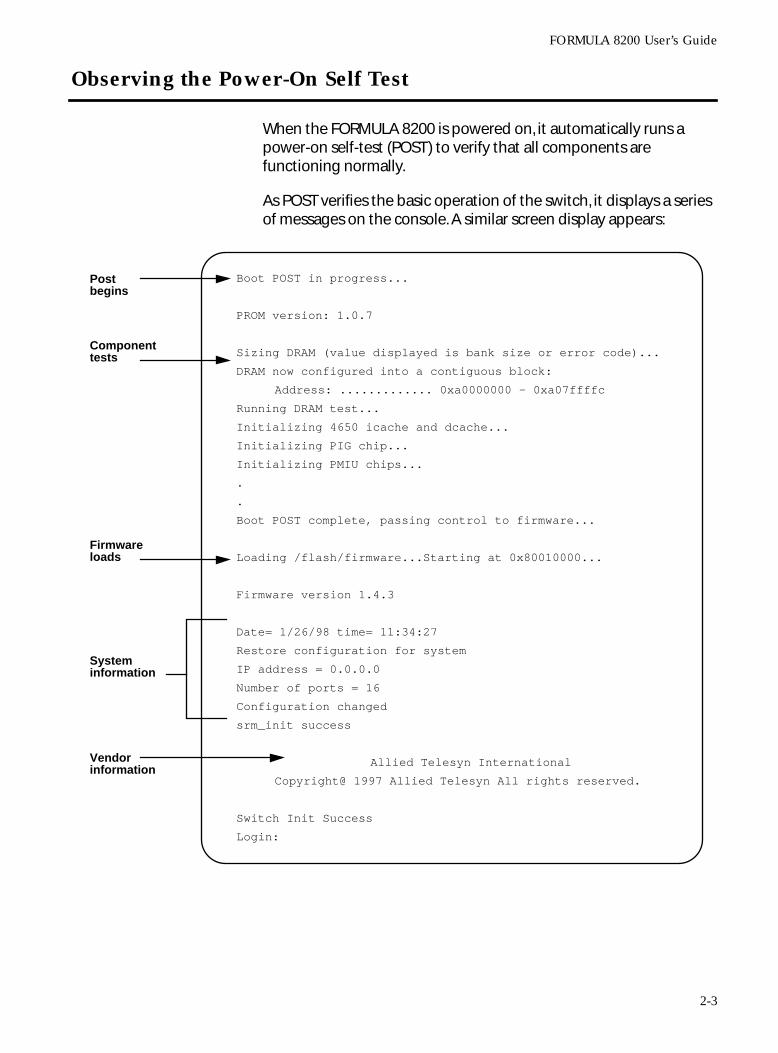
Observing the Power-On Self Test
When the FORMULA 8200 is powered on, it automatically runs a power-on self-test (POST) to verify that all components are functioning normally.
As POST verifies the basic operation of the switch, it displays a series of messages on the console. A similar screen display appears:
Boot POST in progress...
PROM version: 1.0.7
Sizing DRAM (value displayed is bank size or error code)...
DRAM now configured into a contiguous block:
Address: ............. 0xa0000000 - 0xa07ffffc
Running DRAM test...
Initializing 4650 icache and dcache...
Initializing PIG chip...
Initializing PMIU chips...
.
.
Boot POST complete, passing control to firmware...
Loading /flash/firmware...Starting at 0x80010000...
Firmware version 1.4.3
Date= 1/26/98 time= 11:34:27
Restore configuration for system
IP address = 0.0.0.0
Number of ports = 16
Configuration changed
srm_init success
Allied Telesyn International
Copyright@ 1997 Allied Telesyn All rights reserved.
Switch Init Success
Login:
Postbegins
Componenttests
Firmwareloads
Vendorinformation
Systeminformation
2-3
Observing the Power-On Self Test
If any error messages are displayed, report them to the Allied Telesyn’s Technical Support (see Allied Telesyn’s website at www.alliedtelesyn.com) or your reseller. The rest of the messages are for your information only; no action is required.
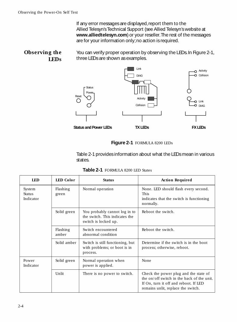
Observing theLEDs
You can verify proper operation by observing the LEDs. In Figure 2-1, three LEDs are shown as examples.
Figure 2-1 FORMULA 8200 LEDs
Table 2-1 provides information about what the LEDs mean in various states.
Status
PowerReset
Link
DIAG
Activity
Collision
Activity
Collision
Link
DIAG
Status and Power LEDs TX LEDs FX LEDs
Table 2-1 FORMULA 8200 LED States
LED LED Color Status Action Required
System Status Indicator
Flashing green
Normal operation None. LED should flash every second. This indicates that the switch is functioning normally.
Solid green You probably cannot log in to the switch. This indicates the switch is locked up.
Reboot the switch.
Flashing amber
Switch encountered abnormal condition
Reboot the switch.
Solid amber Switch is still functioning, but with problems; or boot is in process.
Determine if the switch is in the boot process; otherwise, reboot.
Power Indicator
Solid green Normal operation when power is applied.
None
Unlit There is no power to switch. Check the power plug and the state of the on/off switch in the back of the unit. If On, turn it off and reboot. If LED remains unlit, replace the switch.
2-4
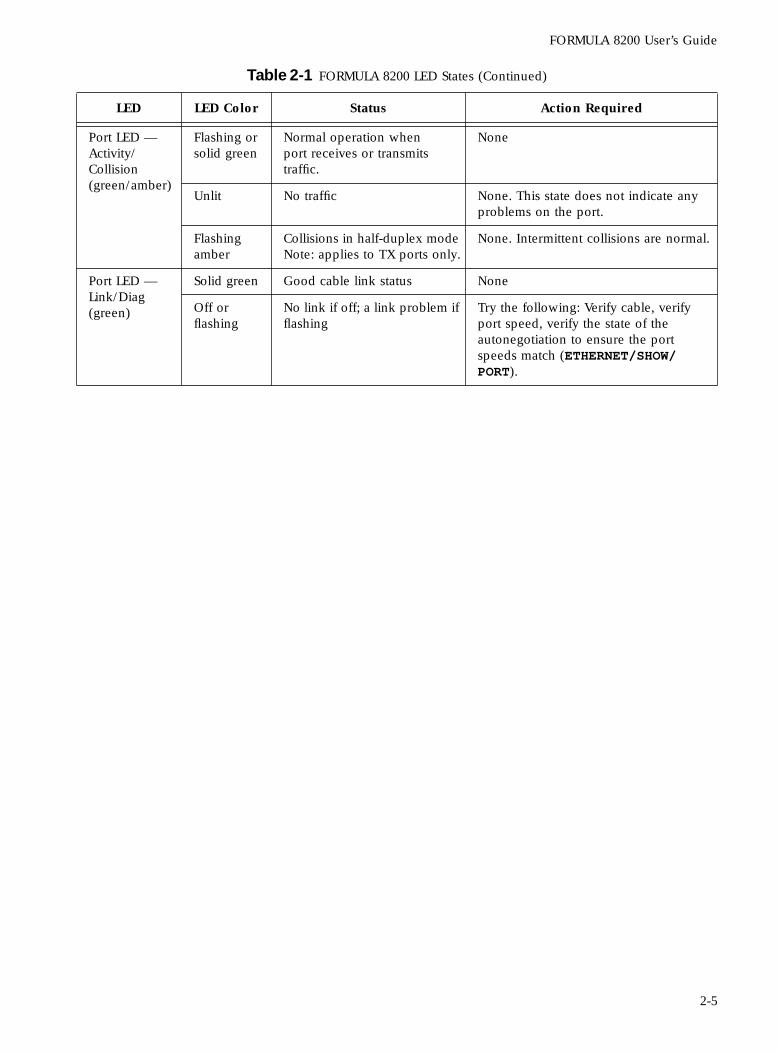
FORMULA 8200 User’s Guide
Port LED — Activity/Collision(green/amber)
Flashing or solid green
Normal operation when port receives or transmits traffic.
None
Unlit No traffic None. This state does not indicate any problems on the port.
Flashing amber
Collisions in half-duplex mode Note: applies to TX ports only.
None. Intermittent collisions are normal.
Port LED — Link/Diag(green)
Solid green Good cable link status None
Off orflashing
No link if off; a link problem if flashing
Try the following: Verify cable, verify port speed, verify the state of the autonegotiation to ensure the port speeds match (ETHERNET/SHOW/PORT).
Table 2-1 FORMULA 8200 LED States (Continued)
LED LED Color Status Action Required
2-5
Logging In
Logging In
The FORMULA 8200 switch ships from the factory with pre-installed software. Once the hardware has been installed, the switch displays the login prompt.
To begin using the CLI:
1. Log in by entering admin in lowercase letters, as follows:
The FORMULA 8200 displays the password prompt.
2. Enter switch, all in lowercase, as follows:
NoteWhen you type your password, the text does not appear on the screen.
After you have entered the password, the FORMULA 8200 command line interface (CLI) prompt is displayed:
For security reasons, change the admin password as soon as possible. To do so, use the SYSTEM/CONFIG/ADMINPW command (explained in detail in Chapter 5).
NoteIf you forget your administrator password, contact Allied Telesyn’s Technical Support. Visit Allied Telesyn’s website at www.alliedtelesyn.com for contact information.
Use the EXIT command to log out from the CLI session.
Login: admin
Password: switch
Login: admin
Password: ******
/>
2-6
FORMULA 8200 User’s Guide
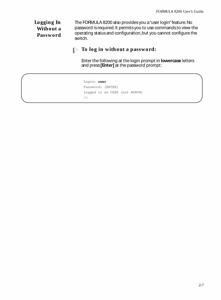
Logging InWithout aPassword
The FORMULA 8200 also provides you a “user login” feature. No password is required. It permits you to use commands to view the operating status and configuration, but you cannot configure the switch.
To log in without a password:
Enter the following at the login prompt in lowercase letters and press [Enter] at the password prompt:
Login: user
Password: [ENTER]
Logged in as USER (not ADMIN)
/>
2-7
Entering Commands
Entering Commands
The FORMULA 8200 command line interface (CLI) is a hierarchical menu-driven interface with menus, submenus, and commands arranged in a tree structure.
To access the main command menu:
Enter ? at the FORMULA 8200 prompt, as shown below.
Enter commands by typing selections from each successive menu; then press [Enter]. You can also enter the entire command at the prompt or you can use an alias; both methods are described in this chapter in Command Formats.
Use of SquareBrackets [ ]
Some commands in the main menu have square brackets around them to indicate that the command requires additional parameters. When you enter one of these commands, a submenu appears that lists the available parameters.
NoteDo not enter the brackets when you enter the command.
Use of AngleBrackets <>
This manual sometimes directs you to enter a command with a variable that is specific to your environment, such as IP addresses. The variables you must supply are enclosed in angle brackets.
For example, to configure a gateway address, enter:
/INET/CONFIG/ROUTE/DEFAULT <default route or gateway IP address>
where <default route or gateway address> can be in the format, 123.123.123.123.
== MAIN MENU ==
/ >
? ALIAS ALLCMD
[ATM] [BOOT] [CONSOLE]
[ELOG] [ETHERNET] EXIT
[FDDI] [FILE] [INET]
LOOKUP [MODE] [PORTSERV]
REBOOT [SNMP] [SYSTEM]
[TFTP] TOP UP
[VBRIDGE] [VLAN] [TRACE]
2-8
FORMULA 8200 User’s Guide
NoteDo not enter the brackets when you enter the command.
The LOOKUPCommand
Entering LOOKUP is a way to get a list of commands, their corresponding aliases, and descriptions.
CommandFormats
The software allows you to enter commands in three ways:
❑ By entering the complete command
❑ By using a shortcut
❑ By using an alias
Separating Command Words
When you enter any command, you may separate the command words with a slash (/). For example:
/FDDI/SHOW/SMT
You may also use a space to separate the command words.
Shortcuts
Use a shortcut by typing the first few characters needed to distinguish the command from others that start with the same letters, such as:
/FD/SH/SMT
This works unless your shortened version is ambiguous, which causes an error message to appear.
Aliases
An alias is an abbreviated command that can be accessed from anywhere in the command line interface. For example, the following alias is equivalent to the FDDI/SHOW/SMT command:
fsmt
Aliases are listed in Appendix A, and are also listed in Chapter 5 with each command description.
2-9
Entering Commands
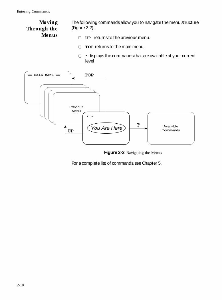
MovingThrough the
Menus
The following commands allow you to navigate the menu structure (Figure 2-2):
❑ UP returns to the previous menu.
❑ TOP returns to the main menu.
❑ ? displays the commands that are available at your current level
Figure 2-2 Navigating the Menus
For a complete list of commands, see Chapter 5.
You Are Here Available Commands
Previous Menu
/ >
UP?
TOP== Main Menu ==
2-10
FORMULA 8200 User’s Guide
Configuring IP Information
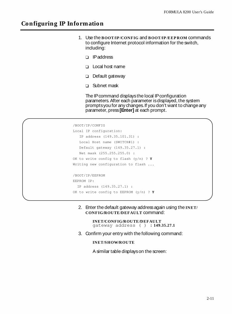
1. Use the BOOT/IP/CONFIG and BOOT/IP/EEPROM commands to configure Internet protocol information for the switch, including:
❑ IP address
❑ Local host name
❑ Default gateway
❑ Subnet mask
The IP command displays the local IP configuration parameters. After each parameter is displayed, the system prompts you for any changes. If you don’t want to change any parameter, press [Enter] at each prompt.
2. Enter the default gateway address again using the INET/CONFIG/ROUTE/DEFAULT command:
INET/CONFIG/ROUTE/DEFAULTgateway address ( ) : 149.35.27.1
3. Confirm your entry with the following command:
INET/SHOW/ROUTE
A similar table displays on the screen:
/BOOT/IP/CONFIG
Local IP configuration:
IP address (149.35.101.31) :
Local Host name (SWITCH#1) :
Default gateway (149.35.27.1) :
Net mask (255.255.255.0) :
OK to write config to flash (y/n) ? Y
Writing new configuration to flash ...
/BOOT/IP/EEPROM
EEPROM IP:
IP address (149.35.27.1) :
OK to write config to EEPROM (y/n) ? Y
2-11
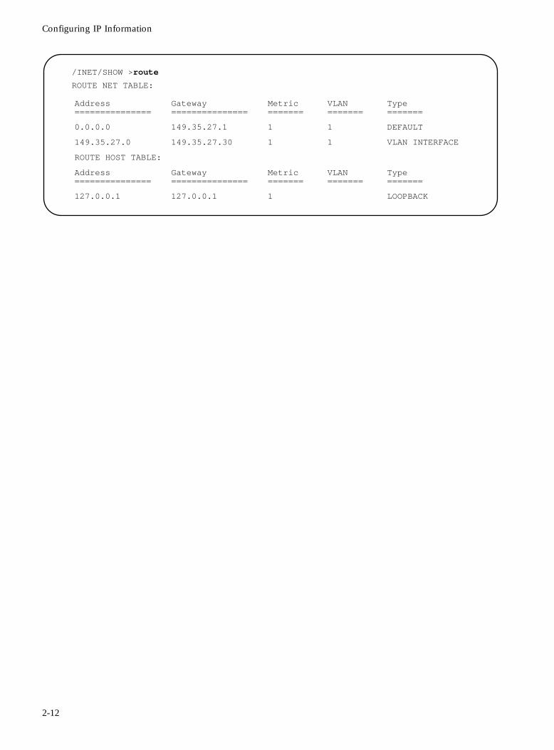
Configuring IP Information
/INET/SHOW >route
ROUTE NET TABLE:
Address ===============
Gateway ===============
Metric =======
VLAN =======
Type=======
0.0.0.0 149.35.27.1 1 1 DEFAULT
149.35.27.0 149.35.27.30 1 1 VLAN INTERFACE
ROUTE HOST TABLE:
Address ===============
Gateway ===============
Metric =======
VLAN =======
Type=======
127.0.0.1 127.0.0.1 1 LOOPBACK
2-12
FORMULA 8200 User’s Guide
Verifying Firmware Information
To ensure that you have the latest information about product features and fixes, verify that the version of any release notes you have received match the version of the firmware installed on the unit.
You also need to verify that the Internet protocol information you entered is correct.
To display firmware information:
Use the SYSTEM/SHOW command.
This displays your overall system configuration. For more information about using this command, see Displaying the System Configuration in Chapter 4; also see the SYSTEM command in Chapter 5.
Updating YourEthernet Ports
Before you connect the FORMULA 8200 to your network, use the ETHERNET/SHOW/PORT command to display, and if necessary, the ETHERNET/CONFIG/PORT command to modify your port configuration. For more details, see the ETHERNET command in Chapter 5.
UpdatingSystem
Information
Use the SYSTEM/CONFIG command to update your system information, including date, time, and admin password. It is especially important to ensure the security of your configuration by updating the admin password as soon as possible.
2-13
Using Telnet to Access the Switch
Using Telnet to Access the Switch
In addition to local console access, you can access the switch from a remote location by using Telnet to make a TCP/IP connection.
The Telnet command syntax depends on the type of terminal or TCP/IP software you are using. Check the appropriate manual for information about connecting to a host using Telnet. Telnet requires the FORMULA 8200’s IP address information has been configured.
To use Telnet to access a remote switch (example):
The following steps initiate a Telnet session to the switch at IP address 123.126.22.77.
1. Enter the Telnet command and the IP address at the system prompt:
telnet 123.126.22.77
2. Enter admin at the login prompt.
Login: admin
3. Enter the password at the password prompt. (If you have not yet changed the default password, enter switch.)
The system prompt now appears, giving you full access to the command line interface.
/ >
4. Use the EXIT command to log out from the CLI session.
NoteThe EXIT command does not end the Telnet session. On certain systems, pressing the CTRL-6, CTRL-], and [Enter] keys in sequence disconnects the Telnet session. Refer to your current Telnet manual for the correct command to disconnect the Telnet session.
2-14
FORMULA 8200 User’s Guide
Resetting and Rebooting the Switch
You may occasionally need to reset the FORMULA 8200. You can do this in one of three ways:
❑ The Reset button on the front panel permits you to perform a “hardware reset,” and does not require you to use the command line interface.
❑ The REBOOT command permits you to reset the switch via the command line interface, either from the local console, or from a remote location via Telnet. The current Telnet session is disconnected by this command.
❑ The On/Off switch in the rear panel recycles the power to the switch.
Either method initializes the hardware, loads the system software from the flash, restores the switch to the current (saved) configuration settings, and restarts the switch. Upon restart, the POST and other diagnostic information appear on the local console, followed by the login and password prompts.
Where to Go Next
Go to Chapter 3, Configuring the FORMULA 8200 Switch, for information about the default switch configurations, to reconfigure the switch for your particular application, or to create VLANs.
2-15

Chapter 3
Configuring the FORMULA 8200 Switch
This chapter describes:
❑ System default configurations
❑ An overview of virtual LANs (VLANs) and related parameters, including Spanning Tree (virtual bridges) and virtual routers, and how to configure them
Default Configurations
The FORMULA 8200 is shipped from the factory with the following default configurations:
❑ Console speed is 9600
❑ Login is admin and password is switch
❑ Autonegotiation is ON (enabled) for 10/100 Mbps TX ports
❑ Ethernet statistics are disabled
❑ All ports belong to the default VLAN 1
❑ Spanning Tree is enabled
❑ RIP (virtual routing) is silent
These settings provide for switching a single broadcast domain. To display and configure port settings, refer to Chapter 4 beginning on page 4-5.
3-1
Optimizing Functionality for Your Application
Optimizing Functionality for Your Application
The FORMULA 8200, unlike shared media switching hubs, allows you to divide your LAN into smaller segments. This increases and uses full LAN bandwidth for each segment. By providing high end devices such as workstations, servers, and routers their own dedicated connections to the switch, you can significantly increase throughput and decrease latency.
In addition to creating one or more VLANs to reduce broadcast traffic, you can also customize the configuration to meet your specific needs. Use the information in the remainder of this chapter; you can also review the command set in Chapter 5 for more specific information.
Virtual LANs
A Virtual LAN (VLAN) is a logical group of LANs or individual devices, established without regard to their physical location on the network. You can group any collection of ports on one or more FORMULA 8200 switches into a VLAN.
Since you can connect either a LAN or a device to a port in the FORMULA 8200, any group of LANs or individual devices connected to the switch can be connected together in a VLAN.
The LAN segments that comprise a VLAN can be distributed among multiple switches that are interconnected by a backbone network. This grouping of LAN segments into VLANs reduces the amount of work required when moving an end station from one LAN segment to another.
VLANs also maximize the efficient use of the bandwidth on any given LAN segment, since packets are forwarded only between segments as required. The separation of segments into VLANs also provides security, since data from a workgroup on one VLAN will not be seen on the VLANs for other workgroups. VLANs also create smaller broadcast domains, which reduce broadcast traffic across the network.
NoteTo communicate between VLANs, the FORMULA 8200 must be configured to enable RIP for IP routing. If additional protocols are required, a connection on each VLAN must go to an external router.
3-2
FORMULA 8200 User’s Guide
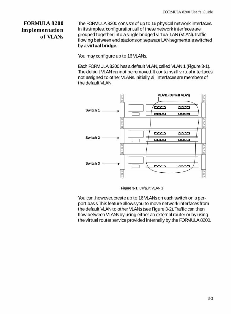
FORMULA 8200Implementation
of VLANs
The FORMULA 8200 consists of up to 16 physical network interfaces. In its simplest configuration, all of these network interfaces are grouped together into a single bridged virtual LAN (VLAN). Traffic flowing between end stations on separate LAN segments is switched by a virtual bridge.
You may configure up to 16 VLANs.
Each FORMULA 8200 has a default VLAN, called VLAN 1 (Figure 3-1). The default VLAN cannot be removed. It contains all virtual interfaces not assigned to other VLANs. Initially, all interfaces are members of the default VLAN.
Figure 3-1: Default VLAN 1
You can, however, create up to 16 VLANs on each switch on a per-port basis. This feature allows you to move network interfaces from the default VLAN to other VLANs (see Figure 3-2). Traffic can then flow between VLANs by using either an external router or by using the virtual router service provided internally by the FORMULA 8200.
VLAN1 (Default VLAN)
Switch 1
Switch 2
Switch 3
3-3
Virtual LANs
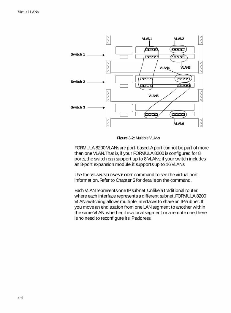
Figure 3-2: Multiple VLANs
FORMULA 8200 VLANs are port-based. A port cannot be part of more than one VLAN. That is, if your FORMULA 8200 is configured for 8 ports, the switch can support up to 8 VLANs; if your switch includes an 8-port expansion module, it supports up to 16 VLANs.
Use the VLAN/SHOW/VPORT command to see the virtual port information. Refer to Chapter 5 for details on the command.
Each VLAN represents one IP subnet. Unlike a traditional router, where each interface represents a different subnet, FORMULA 8200 VLAN switching allows multiple interfaces to share an IP subnet. If you move an end station from one LAN segment to another within the same VLAN, whether it is a local segment or a remote one, there is no need to reconfigure its IP address.
VLAN2
VLAN4
VLAN1
VLAN5
VLAN3
VLAN6
Switch 1
Switch 2
Switch 3
3-4
FORMULA 8200 User’s Guide
Virtual Bridges,Virtual
Interfaces,Virtual Routers
Each VLAN has a virtual bridge that maintains the locations of the end stations on each segment and controls the switching hardware. Each of the interfaces on a virtual bridge is called a virtual interface.
Each VLAN is identified by a number. These numbers are global to all FORMULA 8200 switches that are connected by a backbone network. Traffic can be exchanged over a backbone network in order to allow a VLAN to have segments that are distributed among multiple FORMULA 8200 switches. Traffic can be exchanged between VLANs by either internal or external routing.
Use the VLAN/SHOW/VLAN command to see the virtual VLAN information. Refer to Chapter 5 for details on the command.
An optional virtual router interface can be configured to forward traffic between VLANs by using the VLAN/CONFIG command; see Configuring a Virtual LAN (VLAN) later in this chapter.
Use the VLAN/SHOW/VROUTER command to see the virtual router information. Refer to Chapter 5 for details on the command.
To access the FORMULA 8200 management applications remotely via TCP/IP, the IP interface must be enabled on at least one VLAN (usually VLAN 1). The management applications may then be accessed from a station that has access to one of the LAN segments comprising that VLAN. If the interface over which management functions are taking place is disabled, it is possible to lose contact with the FORMULA 8200. In this case, you must use the console port to reestablish remote TCP/IP management capabilities.
Each VLAN has an associated virtual bridge. A distributed VLAN has one virtual bridge on each FORMULA 8200 that has interfaces participating in the VLAN. The virtual bridge implements the IEEE 802.1-D Spanning Tree Algorithm and Protocol, described in the next section.
Use the VLAN/SHOW/VPORT command to view the virtual port information, and VLAN/SHOW/VSTATS command to view the virtual port statistics.
3-5
Virtual LANs
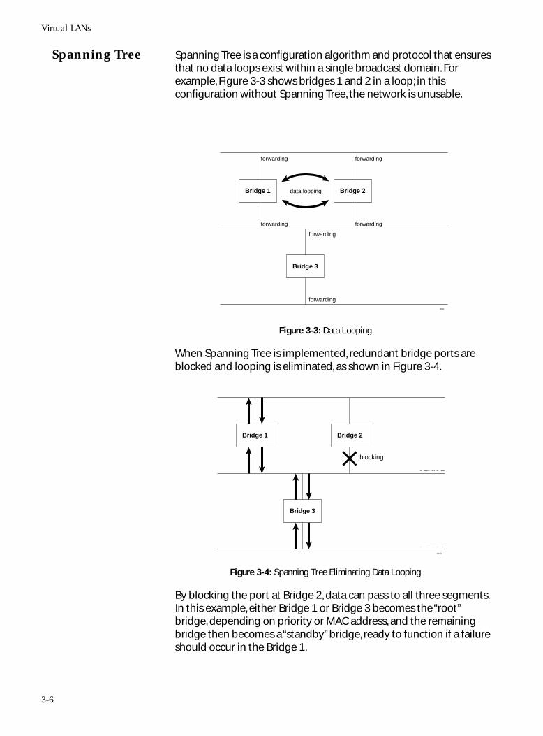
Spanning Tree Spanning Tree is a configuration algorithm and protocol that ensures that no data loops exist within a single broadcast domain. For example, Figure 3-3 shows bridges 1 and 2 in a loop; in this configuration without Spanning Tree, the network is unusable.
Figure 3-3: Data Looping
When Spanning Tree is implemented, redundant bridge ports are blocked and looping is eliminated, as shown in Figure 3-4.
Figure 3-4: Spanning Tree Eliminating Data Looping
By blocking the port at Bridge 2, data can pass to all three segments. In this example, either Bridge 1 or Bridge 3 becomes the “root” bridge, depending on priority or MAC address, and the remaining bridge then becomes a “standby” bridge, ready to function if a failure should occur in the Bridge 1.
forwarding
forwarding
data looping
forwarding
forwarding
forwarding
forwarding
Bridge 1
Bridge 3
Bridge 2
VLAN 1
VLAN 2
VLAN 33011
not forwarding
Bridge 1
Bridge 3
Bridge 2
VLAN 1
VLAN 2
VLAN 33012
blocking
3-6
FORMULA 8200 User’s Guide
In addition to preventing looping, Spanning Tree provides the following functions:
❑ Automatic reconfiguring of the topology in the event of a failure or the addition of a bridge or a bridged port
❑ Topology stability, regardless of the size of the bridged VLAN
❑ Configuration management, by displaying statistics and user-specified bridge and port priorities, parameters, and timers
Spanning Tree performs the above functions by exchanging BPDUs (Bridge Protocol Data Units) packets between bridges. When the topology changes, the time it takes for Spanning Tree to stabilize depends on the size of the bridged network and several user-configurable parameters.
Spanning Tree Protocol functions by putting its ports in the following modes or states:
Blocking State - In this state, ports do not forward packets and do not learn addresses. The ports are in standby mode until a topology change occurs.
Listening State - In this state, ports do not forward packets and do not learn addresses.
Learning State - In this state, ports do not forward packets in either direction, but they learn station addresses.
Forwarding State - In this state, ports forward and learn all packets in either direction.
The listening state and learning state are both temporary states as the port moves into forwarding state.
Use the VBRIDGE/SHOW/BRIDGE<VLAN#> command to view the current configuration settings.
To enable and configure Spanning Tree, use the VBRIDGE/CONFIG/BRIDGE<VLAN#> command, or refer to Configuring a Virtual Bridge later in this chapter.
3-7
Configuring a Virtual LAN (VLAN)
Configuring a Virtual LAN (VLAN)
Use this procedure to assign ports to create a VLAN, including a virtual router, if desired. By default, all the ports on your FORMULA 8200 are assigned to VLAN 1. If this configuration suits your needs, use VLAN 1 to define port assignments. Otherwise, create more VLANs to establish user groups and manage network traffic.
As you create additional VLANs, the ports you assign to them are removed from VLAN 1 (that is, a port cannot be in two VLANs at the same time).
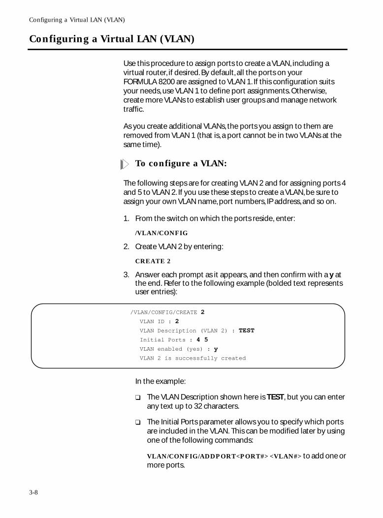
To configure a VLAN:
The following steps are for creating VLAN 2 and for assigning ports 4 and 5 to VLAN 2. If you use these steps to create a VLAN, be sure to assign your own VLAN name, port numbers, IP address, and so on.
1. From the switch on which the ports reside, enter:
/VLAN/CONFIG
2. Create VLAN 2 by entering:
CREATE 2
3. Answer each prompt as it appears, and then confirm with a y at the end. Refer to the following example (bolded text represents user entries):
In the example:
❑ The VLAN Description shown here is TEST, but you can enter any text up to 32 characters.
❑ The Initial Ports parameter allows you to specify which ports are included in the VLAN. This can be modified later by using one of the following commands:
VLAN/CONFIG/ADDPORT<PORT#> <VLAN#> to add one or more ports.
/VLAN/CONFIG/CREATE 2
VLAN ID : 2
VLAN Description (VLAN 2) : TEST
Initial Ports : 4 5
VLAN enabled (yes) : y
VLAN 2 is successfully created
3-8
FORMULA 8200 User’s Guide
VLAN/CONFIG/MOVPORT to move one or more ports.
VLAN/CONFIG/DELPORT<PORT#> <VLAN#> to delete one or more ports.
You can also use the following commands to change VLAN configuration:
VLAN/CONFIG/MODIFY <VLAN#> to modify a VLAN.
VLAN/CONFIG/REMOVE <VLAN#> to remove a VLAN.
VLAN/CONFIG/ENABLE <VLAN#> to enable the entire VLAN.
VLAN/CONFIG/DISABLE <VLAN#> to disable the entire VLAN.
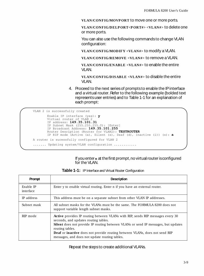
4. Proceed to the next series of prompts to enable the IP interface and a virtual router. Refer to the following example (bolded text represents user entries) and to Table 1-1 for an explanation of each prompt:
If you enter n at the first prompt, no virtual router is configured for the VLAN.
Repeat the steps to create additional VLANs.
VLAN 2 is successfully created
Enable IP interface (yes): yVirtual router of VLAN 2IP address: 149.35.101.31IP Subnet Mask (255.255.255.0): [Enter]IP Broadcast Address: 149.35.101.255Router Desription (Router for VLAN2): TESTROUTERIP RIP mode (Active (a), Silent (s), Deaf (d), Inactive (i)) (s): a
A router is sucessfully configured for VLAN 2
....... Updating system/VLAN configuration ............
Table 1-1: IP Interface and Virtual Router Configuration
Prompt Description
Enable IP interface
Enter y to enable virtual routing. Enter n if you have an external router.
IP address This address must be on a separate subnet from other VLAN IP addresses.
Subnet mask All subnet masks for the VLANs must be the same. The FORMULA 8200 does not support variable length subnet masks.
RIP mode Active provides IP routing between VLANs with RIP, sends RIP messages every 30 seconds, and updates routing tables.Silent does not provide IP routing between VLANs or send IP messages, but updates routing tables.Deaf or inactive does not provide routing between VLANs, does not send RIP messages, and does not update routing tables.
3-9
Configuring a Virtual LAN (VLAN)
To display the configuration of a virtual LAN:
Use the VLAN/SHOW/VLAN <VLAN#> command.
The following is an example configuration display of the previously-created VLAN 2:
VLAN/SHOW/VLAN 2
VLAN ID:2
VLAN Description:TEST
Router Description:TESTROUTER
Network Address:149.35.101.31
Subnetwork Mask:255.255.255.0
Broadcast Address:149.35.101.255
Admin Status:EMABLE
Operation Status:ACTIVE
Port Members:
VirtualPort ID=======
PhysicalPort ID=======
VLANID====
PortType====
PortMAC Address===========
BridgeState======
AdminStatus======
OperationStatus==========
4 4 2 Bridge 0:60:e8:ff:ff:23 Disable Enable Inactive
5 5 2 Bridge 0:60:e8:ff:ff:24 Forward Enable Active
18 33 2 Router 0:60:e8:ff:ff:50 Enable Active
3-10
FORMULA 8200 User’s Guide
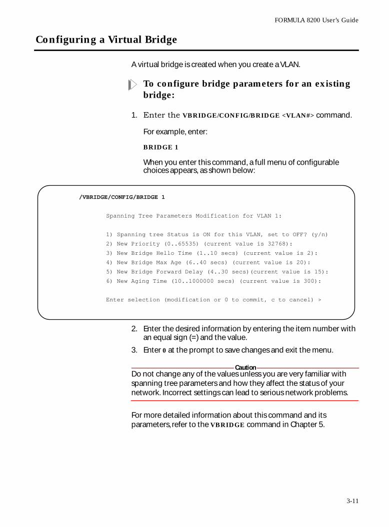
Configuring a Virtual Bridge
A virtual bridge is created when you create a VLAN.
To configure bridge parameters for an existing bridge:
1. Enter the VBRIDGE/CONFIG/BRIDGE <VLAN#> command.
For example, enter:
BRIDGE 1
When you enter this command, a full menu of configurable choices appears, as shown below:
2. Enter the desired information by entering the item number with an equal sign (=) and the value.
3. Enter 0 at the prompt to save changes and exit the menu.
CautionDo not change any of the values unless you are very familiar with spanning tree parameters and how they affect the status of your network. Incorrect settings can lead to serious network problems.
For more detailed information about this command and its parameters, refer to the VBRIDGE command in Chapter 5.
/VBRIDGE/CONFIG/BRIDGE 1
Spanning Tree Parameters Modification for VLAN 1:
1) Spanning tree Status is ON for this VLAN, set to OFF? (y/n)
2) New Priority (0..65535) (current value is 32768):
3) New Bridge Hello Time (1..10 secs) (current value is 2):
4) New Bridge Max Age (6..40 secs) (current value is 20):
5) New Bridge Forward Delay (4..30 secs)(current value is 15):
6) New Aging Time (10..1000000 secs) (current value is 300):
Enter selection (modification or 0 to commit, c to cancel) >
3-11
Configuring a Virtual Bridge
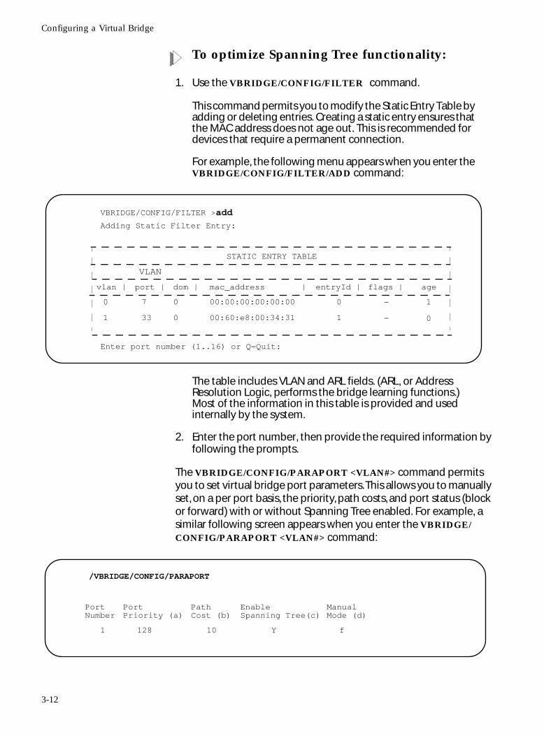
To optimize Spanning Tree functionality:
1. Use the VBRIDGE/CONFIG/FILTER command.
This command permits you to modify the Static Entry Table by adding or deleting entries. Creating a static entry ensures that the MAC address does not age out. This is recommended for devices that require a permanent connection.
For example, the following menu appears when you enter the VBRIDGE/CONFIG/FILTER/ADD command:
The table includes VLAN and ARL fields. (ARL, or Address Resolution Logic, performs the bridge learning functions.) Most of the information in this table is provided and used internally by the system.
2. Enter the port number, then provide the required information by following the prompts.
The VBRIDGE/CONFIG/PARAPORT <VLAN#> command permits you to set virtual bridge port parameters. This allows you to manually set, on a per port basis, the priority, path costs, and port status (block or forward) with or without Spanning Tree enabled. For example, a similar following screen appears when you enter the VBRIDGE/CONFIG/PARAPORT <VLAN#> command:
VBRIDGE/CONFIG/FILTER >add
Adding Static Filter Entry:
Enter port number (1..16) or Q=Quit:
STATIC ENTRY TABLE
VLAN
vlan | port | dom | mac_address | entryId | flags | age
0 7 0 00:00:00:00:00:00 0 — 1
1 33 0 00:60:e8:00:34:31 1 — 0
/VBRIDGE/CONFIG/PARAPORT
PortNumber
PortPriority (a)
PathCost (b)
EnableSpanning Tree(c)
ManualMode (d)
1 128 10 Y f
3-12

FORMULA 8200 User’s Guide
To display virtual bridge parameters:
Use the VBRIDGE/SHOW/BRIDGE <VLAN#> command.
See Chapter 5, Command Reference, for more information.
3-13

Chapter 4
Operating and Managing the FORMULA 8200 Switch
This chapter provides an overview of tasks that you may want to perform in the course of normal operation, including displaying or configuring parameters related to the following:
❑ System configuration
❑ Internet Protocol (IP)
❑ Ethernet configuration
❑ Port mirroring
❑ Virtual LANs
❑ Virtual bridges
❑ Spanning Tree
❑ RIP
❑ Firmware upgrades
4-1
Operating and Managing the FORMULA 8200 Switch
Using Online Help
Use the following command to obtain online information about the CLI:
For additional information about using these commands (and all FORMULA 8200 commands), see Chapter 5.
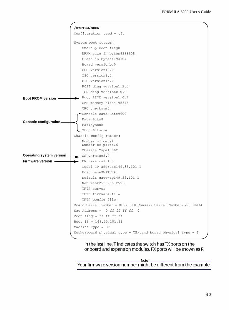
Displaying the System Configuration
The FORMULA 8200 SYSTEM/SHOW command displays system information, including the version numbers of your:
❑ Boot PROM
❑ Firmware
❑ Operating system
❑ Chassis type
❑ Board serial number
❑ Chassis serial number
❑ MAC address
The SYSTEM command also displays your Internet configuration data:
❑ Local IP address
❑ Host name
❑ Default gateway
❑ Subnet mask
To display system information:
Enter the SYSTEM/SHOW command. A similar screen appears:
ALIAS Lists command shortcuts and briefly describes each.
ALLCMD List available commands and briefly describes each.
LOOKUP Displays information about a specific command.
HELP <COMMAND> Provides brief descriptions of command usage.
4-2
FORMULA 8200 User’s Guide
In the last line, T indicates the switch has TX ports on the onboard and expansion modules. FX ports will be shown as F.
NoteYour firmware version number might be different from the example.
/SYSTEM/SHOW
Configuration used = cfg
System boot sector:
Startup boot flag0
DRAM size in bytes8388608
Flash in bytes4194304
Board versionb.0
CPU version10.0
ISC version1.0
PIG version15.0
POST diag version1.2.0
ISD diag version0.0.0
Boot PROM version1.0.7
QME memory size4195316
CRC checksum0
Console Baud Rate9600
Data Bits8
Paritynone
Stop Bitsone
Chassis configuration:
Number of qmus4Number of ports16
Chassis Type10002
OS version5.2
FW version1.4.3
Local IP address149.35.101.1
Host nameSWITCH#1
Default gateway149.35.101.1
Net mask255.255.255.0
TFTP server
TFTP firmware file
TFTP config file
Board Serial number = H6970318 Chassis Serial Number= JS000434
Mac Address = 0 ff ff ff ff 0
Boot flag = ff ff ff ff
Boot IP = 149.35.101.31
Machine Type = BT
Motherboard physical type = TExpand board physical type = T
Boot PROM version
Console configuration
Operating system version
Firmware version
4-3
Operating and Managing the FORMULA 8200 Switch
Displaying Console Port Parameters
To display the console parameters:
Use the CONSOLE command. You can perform the following functions:
For additional information about using these commands, refer to CONSOLE Command in Chapter 5.
CONSOLE/LOCK 1 Locks the console from remote sessions.
CONSOLE/LOCK 0 Unlocks the console from remote sessions.
CONSOLE/SHOW Displays the console parameters.
4-4
FORMULA 8200 User’s Guide
Displaying Ethernet Port Settings Information
To display Ethernet port information:
Use the ETHERNET/SHOW/PORT command. The following screen shows the port configuration for a FORMULA 8200 switch with 8 TX ports and 8 FX expansion ports.
/ETHERNET/SHOW> port
Physical Port# ==============
Autoneg =======
Speed =======
Duplex =======
1 on 100MBPS HALF
2 on 100MBPS HALF
3 on 100MBPS HALF
4 on 100MBPS HALF
5 on 100MBPS HALF
6 on 100MBPS HALF
7 on 100MBPS HALF
8 on 100MBPS HALF
9 off 100MBPS FULL
10 off 100MBPS FULL
11 off 100MBPS FULL
12 off 100MBPS FULL
13 off 100MBPS FULL
14 off 100MBPS FULL
15 off 100MBPS FULL
16 off 100MBPS FULL
FX ports
4-5
Operating and Managing the FORMULA 8200 Switch
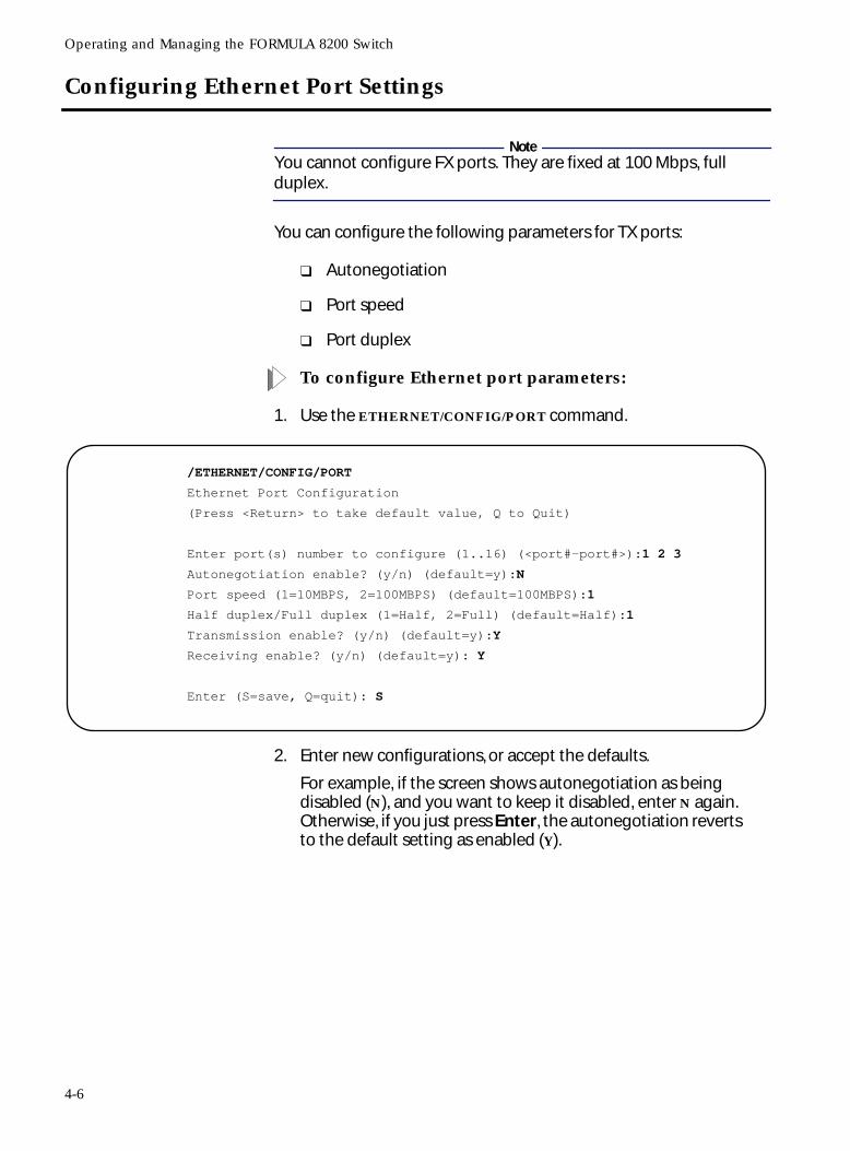
Configuring Ethernet Port Settings
NoteYou cannot configure FX ports. They are fixed at 100 Mbps, full duplex.
You can configure the following parameters for TX ports:
❑ Autonegotiation
❑ Port speed
❑ Port duplex
To configure Ethernet port parameters:
1. Use the ETHERNET/CONFIG/PORT command.
2. Enter new configurations, or accept the defaults.
For example, if the screen shows autonegotiation as being disabled (N), and you want to keep it disabled, enter N again. Otherwise, if you just press Enter, the autonegotiation reverts to the default setting as enabled (Y).
/ETHERNET/CONFIG/PORT
Ethernet Port Configuration
(Press <Return> to take default value, Q to Quit)
Enter port(s) number to configure (1..16) (<port#-port#>):1 2 3
Autonegotiation enable? (y/n) (default=y):N
Port speed (1=10MBPS, 2=100MBPS) (default=100MBPS):1
Half duplex/Full duplex (1=Half, 2=Full) (default=Half):1
Transmission enable? (y/n) (default=y):Y
Receiving enable? (y/n) (default=y): Y
Enter (S=save, Q=quit): S
4-6
FORMULA 8200 User’s Guide
Configuring Ethernet Port Statistics
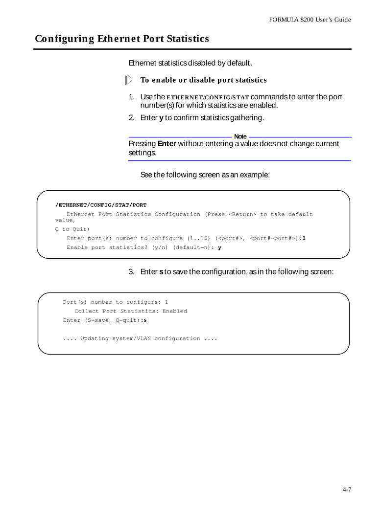
Ethernet statistics disabled by default.
To enable or disable port statistics
1. Use the ETHERNET/CONFIG/STAT commands to enter the port number(s) for which statistics are enabled.
2. Enter y to confirm statistics gathering.
NotePressing Enter without entering a value does not change current settings.
See the following screen as an example:
3. Enter s to save the configuration, as in the following screen:
/ETHERNET/CONFIG/STAT/PORT
Ethernet Port Statistics Configuration (Press <Return> to take default value,
Q to Quit)
Enter port(s) number to configure (1..16) (<port#>, <port#-port#>):1
Enable port statistics? (y/n) (default=n): y
Port(s) number to configure: 1
Collect Port Statistics: Enabled
Enter (S=save, Q=quit):s
.... Updating system/VLAN configuration ....
4-7
Operating and Managing the FORMULA 8200 Switch
Displaying Ethernet Port Statistics Information
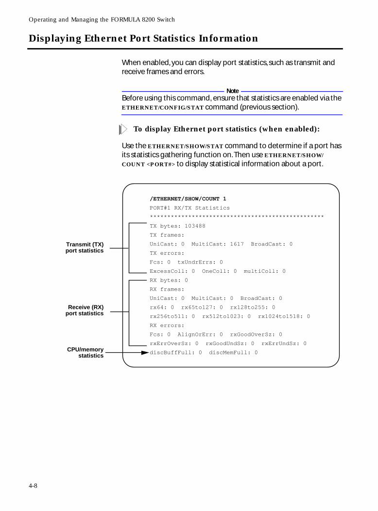
When enabled, you can display port statistics, such as transmit and receive frames and errors.
NoteBefore using this command, ensure that statistics are enabled via the ETHERNET/CONFIG/STAT command (previous section).
To display Ethernet port statistics (when enabled):
Use the ETHERNET/SHOW/STAT command to determine if a port has its statistics gathering function on. Then use ETHERNET/SHOW/
COUNT <PORT#> to display statistical information about a port.
/ETHERNET/SHOW/COUNT 1
PORT#1 RX/TX Statistics
**************************************************
TX bytes: 103488
TX frames:
UniCast: 0 MultiCast: 1617 BroadCast: 0
TX errors:
Fcs: 0 txUndrErrs: 0
ExcessColl: 0 OneColl: 0 multiColl: 0
RX bytes: 0
RX frames:
UniCast: 0 MultiCast: 0 BroadCast: 0
rx64: 0 rx65to127: 0 rx128to255: 0
rx256to511: 0 rx512to1023: 0 rx1024to1518: 0
RX errors:
Fcs: 0 AlignOrErr: 0 rxGoodOverSz: 0
rxErrOverSz: 0 rxGoodUndSz: 0 rxErrUndSz: 0
discBuffFull: 0 discMemFull: 0
Transmit (TX)port statistics
Receive (RX)port statistics
CPU/memorystatistics
4-8
FORMULA 8200 User’s Guide
Clearing a Port’s Statistics Counters
To clear a port’s statistics counters:
Use the ETHERNET/CONFIG/CLEAR <PORT#> command.
This command resets the port’s statistics to 0. If polling is enabled, the counters begin to increment at the next polling interval.
Using Ethernet Port Mirroring
You need to provide a network analyzer to monitor traffic on the FORMULA 8200.
Port mirroring lets you nonintrusively monitor the network traffic on one port from another port. You can set up port mirroring for any pair of Ethernet ports within the same switch. When you enable port mirroring, the active or mirrored port transmits and receives normally, and the mirroring or snoop port receives a copy of the receive traffic of that active port.
NoteBefore using the port mirroring feature, you must enable port statistics hardware and statistics polling by using the ETHERNET/
CONFIG/STAT command.
The following procedure shows you how to configure port mirroring using four basic steps:
❑ Configure the snoop port to mirror receive (rx) traffic
❑ Configure the port to be monitored
❑ Verify the configuration
❑ View the mirrored information
At the end of this section, a procedure also shows you how to clear the snoop port.
4-9
Operating and Managing the FORMULA 8200 Switch
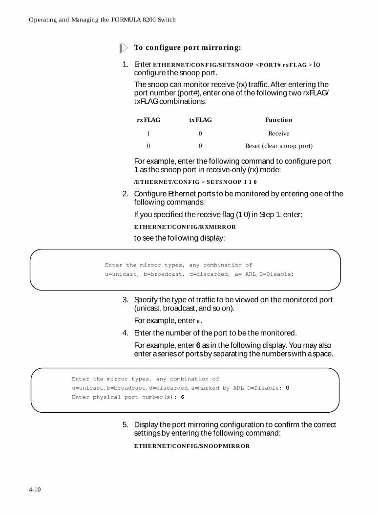
To configure port mirroring:
1. Enter ETHERNET/CONFIG/SETSNOOP <PORT# rxFLAG > to configure the snoop port.
The snoop can monitor receive (rx) traffic. After entering the port number (port#), enter one of the following two rxFLAG/txFLAG combinations:
For example, enter the following command to configure port 1 as the snoop port in receive-only (rx) mode:
/ETHERNET/CONFIG > SETSNOOP 1 1 0
2. Configure Ethernet ports to be monitored by entering one of the following commands:
If you specified the receive flag (1 0) in Step 1, enter:
ETHERNET/CONFIG/RXMIRROR
to see the following display:
3. Specify the type of traffic to be viewed on the monitored port (unicast, broadcast, and so on).
For example, enter u.
4. Enter the number of the port to be the monitored.
For example, enter 6 as in the following display. You may also enter a series of ports by separating the numbers with a space.
5. Display the port mirroring configuration to confirm the correct settings by entering the following command:
ETHERNET/CONFIG/SNOOPMIRROR
rxFLAG txFLAG Function
1 0 Receive
0 0 Reset (clear snoop port)
Enter the mirror types, any combination of
u=unicast, b=broadcast, d=discarded, a= ARL,D=Disable:
Enter the mirror types, any combination of
u=unicast,b=broadcast,d=discarded,a=marked by ARL,D=Disable: U
Enter physical port number(s): 6
4-10
FORMULA 8200 User’s Guide
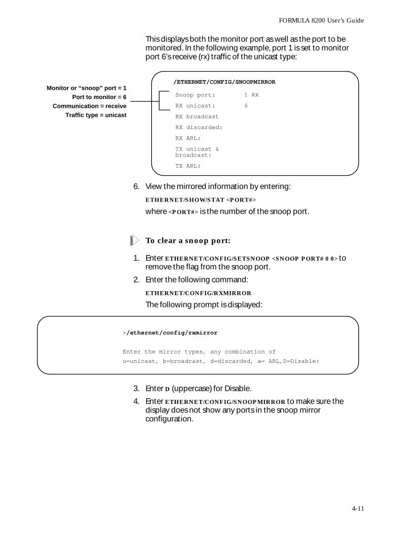
This displays both the monitor port as well as the port to be monitored. In the following example, port 1 is set to monitor port 6’s receive (rx) traffic of the unicast type:
6. View the mirrored information by entering:
ETHERNET/SHOW/STAT <PORT#>
where <PORT#> is the number of the snoop port.
To clear a snoop port:
1. Enter ETHERNET/CONFIG/SETSNOOP <SNOOP PORT# 0 0> to remove the flag from the snoop port.
2. Enter the following command:
ETHERNET/CONFIG/RXMIRROR
The following prompt is displayed:
3. Enter D (uppercase) for Disable.
4. Enter ETHERNET/CONFIG/SNOOPMIRROR to make sure the display does not show any ports in the snoop mirror configuration.
/ETHERNET/CONFIG/SNOOPMIRROR
Snoop port: 1 RX
RX unicast: 6
RX broadcast
RX discarded:
RX ARL:
TX unicast & broadcast:
TX ARL:
Monitor or “snoop” port = 1Port to monitor = 6
Communication = receiveTraffic type = unicast
>/ethernet/config/rxmirror
Enter the mirror types, any combination of
u=unicast, b=broadcast, d=discarded, a= ARL,D=Disable:
4-11
Operating and Managing the FORMULA 8200 Switch
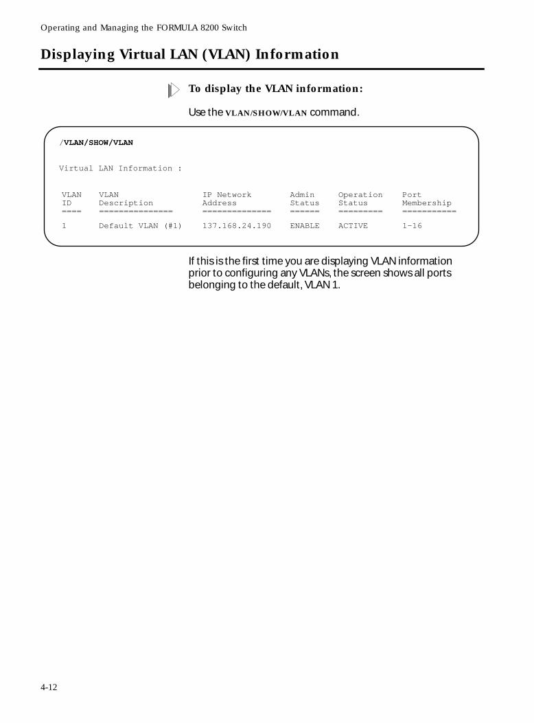
Displaying Virtual LAN (VLAN) Information
To display the VLAN information:
Use the VLAN/SHOW/VLAN command.
If this is the first time you are displaying VLAN information prior to configuring any VLANs, the screen shows all ports belonging to the default, VLAN 1.
/VLAN/SHOW/VLAN
Virtual LAN Information :
VLANID====
VLANDescription===============
IP NetworkAddress==============
AdminStatus======
OperationStatus=========
PortMembership===========
1 Default VLAN (#1) 137.168.24.190 ENABLE ACTIVE 1-16
4-12
FORMULA 8200 User’s Guide
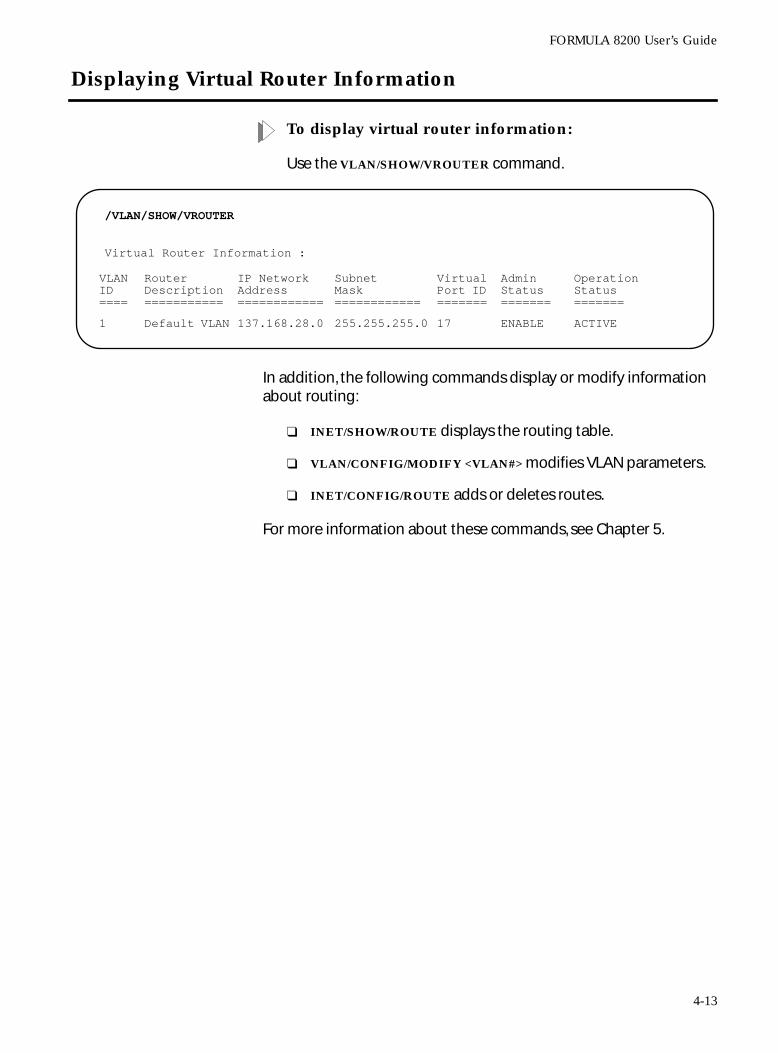
Displaying Virtual Router Information
To display virtual router information:
Use the VLAN/SHOW/VROUTER command.
In addition, the following commands display or modify information about routing:
❑ INET/SHOW/ROUTE displays the routing table.
❑ VLAN/CONFIG/MODIFY <VLAN#> modifies VLAN parameters.
❑ INET/CONFIG/ROUTE adds or deletes routes.
For more information about these commands, see Chapter 5.
/VLAN/SHOW/VROUTER
Virtual Router Information :
VLANID ====
Router Description ===========
IP Network Address ============
SubnetMask ============
VirtualPort ID =======
Admin Status =======
Operation Status =======
1 Default VLAN 137.168.28.0 255.255.255.0 17 ENABLE ACTIVE
4-13
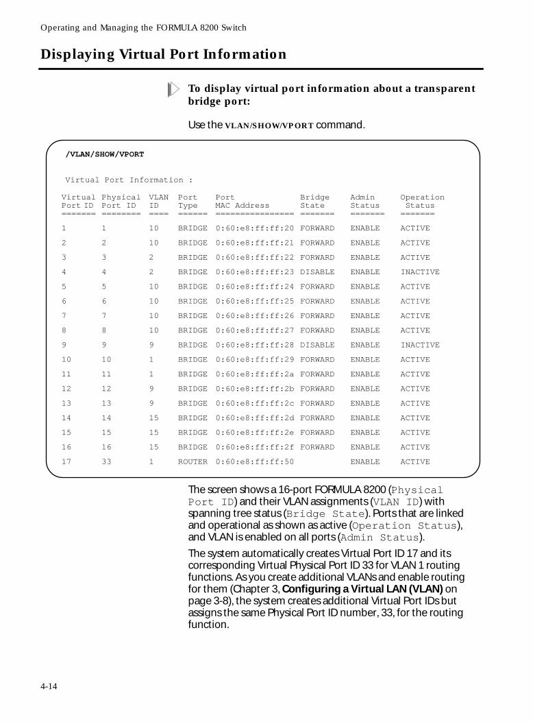
Operating and Managing the FORMULA 8200 Switch
Displaying Virtual Port Information
To display virtual port information about a transparent bridge port:
Use the VLAN/SHOW/VPORT command.
The screen shows a 16-port FORMULA 8200 (Physical Port ID) and their VLAN assignments (VLAN ID) with spanning tree status (Bridge State). Ports that are linked and operational as shown as active (Operation Status), and VLAN is enabled on all ports (Admin Status).
The system automatically creates Virtual Port ID 17 and its corresponding Virtual Physical Port ID 33 for VLAN 1 routing functions. As you create additional VLANs and enable routing for them (Chapter 3, Configuring a Virtual LAN (VLAN) on page 3-8), the system creates additional Virtual Port IDs but assigns the same Physical Port ID number, 33, for the routing function.
/VLAN/SHOW/VPORT
Virtual Port Information :
VirtualPort ID =======
PhysicalPort ID ========
VLAN ID ====
Port Type ======
PortMAC Address ================
Bridge State =======
Admin Status =======
Operation Status =======
1 1 10 BRIDGE 0:60:e8:ff:ff:20 FORWARD ENABLE ACTIVE
2 2 10 BRIDGE 0:60:e8:ff:ff:21 FORWARD ENABLE ACTIVE
3 3 2 BRIDGE 0:60:e8:ff:ff:22 FORWARD ENABLE ACTIVE
4 4 2 BRIDGE 0:60:e8:ff:ff:23 DISABLE ENABLE INACTIVE
5 5 10 BRIDGE 0:60:e8:ff:ff:24 FORWARD ENABLE ACTIVE
6 6 10 BRIDGE 0:60:e8:ff:ff:25 FORWARD ENABLE ACTIVE
7 7 10 BRIDGE 0:60:e8:ff:ff:26 FORWARD ENABLE ACTIVE
8 8 10 BRIDGE 0:60:e8:ff:ff:27 FORWARD ENABLE ACTIVE
9 9 9 BRIDGE 0:60:e8:ff:ff:28 DISABLE ENABLE INACTIVE
10 10 1 BRIDGE 0:60:e8:ff:ff:29 FORWARD ENABLE ACTIVE
11 11 1 BRIDGE 0:60:e8:ff:ff:2a FORWARD ENABLE ACTIVE
12 12 9 BRIDGE 0:60:e8:ff:ff:2b FORWARD ENABLE ACTIVE
13 13 9 BRIDGE 0:60:e8:ff:ff:2c FORWARD ENABLE ACTIVE
14 14 15 BRIDGE 0:60:e8:ff:ff:2d FORWARD ENABLE ACTIVE
15 15 15 BRIDGE 0:60:e8:ff:ff:2e FORWARD ENABLE ACTIVE
16 16 15 BRIDGE 0:60:e8:ff:ff:2f FORWARD ENABLE ACTIVE
17 33 1 ROUTER 0:60:e8:ff:ff:50 ENABLE ACTIVE
4-14
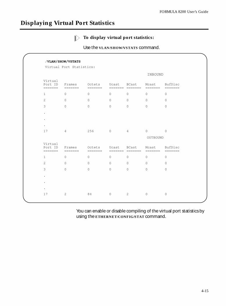
FORMULA 8200 User’s Guide
Displaying Virtual Port Statistics
To display virtual port statistics:
Use the VLAN/SHOW/VSTATS command.
You can enable or disable compiling of the virtual port statistics by using the ETHERNET/CONFIG/STAT command.
/VLAN/SHOW/VSTATS
Virtual Port Statistics:
INBOUND
VirtualPort ID =======
Frames=======
Octets=======
Ucast =======
BCast =======
Mcast =======
BufDisc =======
1 0 0 0 0 0 0
2 0 0 0 0 0 0
3 0 0 0 0 0 0
.
.
.
17 4 256 0 4 0 0
OUTBOUND
VirtualPort ID =======
Frames=======
Octets=======
Ucast =======
BCast =======
Mcast =======
BufDisc =======
1 0 0 0 0 0 0
2 0 0 0 0 0 0
3 0 0 0 0 0 0
.
.
.
17 2 84 0 2 0 0
4-15
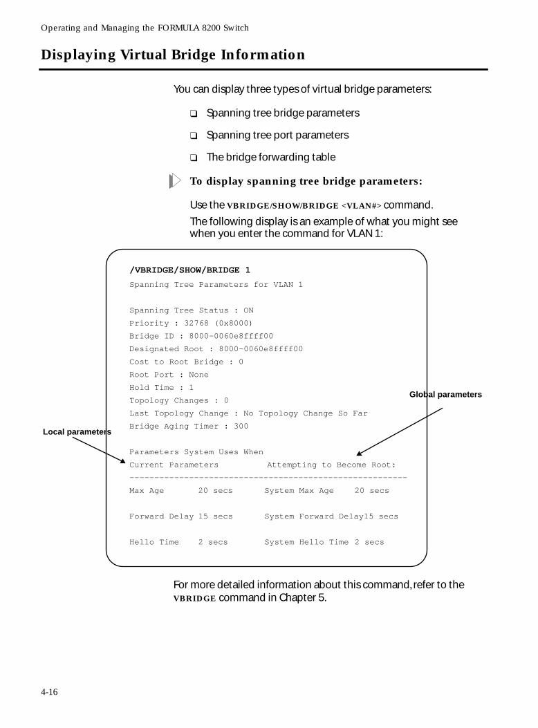
Operating and Managing the FORMULA 8200 Switch
Displaying Virtual Bridge Information
You can display three types of virtual bridge parameters:
❑ Spanning tree bridge parameters
❑ Spanning tree port parameters
❑ The bridge forwarding table
To display spanning tree bridge parameters:
Use the VBRIDGE/SHOW/BRIDGE <VLAN#> command.
The following display is an example of what you might see when you enter the command for VLAN 1:
For more detailed information about this command, refer to the VBRIDGE command in Chapter 5.
/VBRIDGE/SHOW/BRIDGE 1
Spanning Tree Parameters for VLAN 1
Spanning Tree Status : ON
Priority : 32768 (0x8000)
Bridge ID : 8000-0060e8ffff00
Designated Root : 8000-0060e8ffff00
Cost to Root Bridge : 0
Root Port : None
Hold Time : 1
Topology Changes : 0
Last Topology Change : No Topology Change So Far
Bridge Aging Timer : 300
Parameters System Uses When
Current Parameters Attempting to Become Root:
--------------------------------------------------------
Max Age 20 secs System Max Age 20 secs
Forward Delay 15 secs System Forward Delay15 secs
Hello Time 2 secs System Hello Time 2 secs
Local parameters
Global parameters
4-16
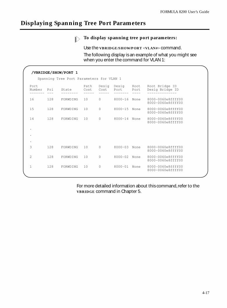
FORMULA 8200 User’s Guide
Displaying Spanning Tree Port Parameters
To display spanning tree port parameters:
Use the VBRIDGE/SHOW/PORT <VLAN#> command.
The following display is an example of what you might see when you enter the command for VLAN 1:
For more detailed information about this command, refer to the VBRIDGE command in Chapter 5.
/VBRIDGE/SHOW/PORT 1
Spanning Tree Port Parameters for VLAN 1
PortNumber -------
Pri---
State--------
PathCost-----
DesigCost-----
DesigPort-------
RootPort----
Root Bridge IDDesig Bridge ID--------------
16 128 FORWDING 10 0 8000-16 None 8000-0060e8ffff00 8000-0060e8ffff00
15 128 FORWDING 10 0 8000-15 None 8000-0060e8ffff00 8000-0060e8ffff00
14 128 FORWDING 10 0 8000-14 None 8000-0060e8ffff00 8000-0060e8ffff00
.
.
.
3 128 FORWDING 10 0 8000-03 None 8000-0060e8ffff00 8000-0060e8ffff00
2 128 FORWDING 10 0 8000-02 None 8000-0060e8ffff00 8000-0060e8ffff00
1 128 FORWDING 10 0 8000-01 None 8000-0060e8ffff00 8000-0060e8ffff00
4-17
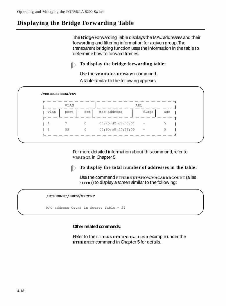
Operating and Managing the FORMULA 8200 Switch
Displaying the Bridge Forwarding Table
The Bridge Forwarding Table displays the MAC addresses and their forwarding and filtering information for a given group. The transparent bridging function uses the information in the table to determine how to forward frames.
To display the bridge forwarding table:
Use the VBRIDGE/SHOW/FWT command.
A table similar to the following appears:
For more detailed information about this command, refer to VBRIDGE in Chapter 5.
To display the total number of addresses in the table:
Use the command ETHERNET/SHOW/MACADDRCOUNT (alias srccnt) to display a screen similar to the following:
Other related commands:
Refer to the ETHERNET/CONFIG/FLUSH example under the ETHERNET command in Chapter 5 for details.
/VBRIDGE/SHOW/FWT
VLAN ARL
vlan port dom mac_address flags age
1 7 0 00:a0:d2:c1:55:01 — 5
1 33 0 00:60:e8:ff:ff:50 — 0
/ETHERNET/SHOW/SRCCNT
MAC address Count in Source Table = 22
4-18
FORMULA 8200 User’s Guide
Upgrading Firmware
This section describes the procedures for using TFTP to download the FORMULA 8200 system software (image file, binary) from your TFTP server to the FORMULA 8200 switch.
Prior to the TFTP download process:
1. Your TFTP server must be running the TFTP daemon (UNIX) or a TFTP process (DOS/Windows). Without the daemon or the process, your download from your server will fail.
2. If you have Solaris , refer to Appendix B for the procedures to configure a TFTP server on that platform.
3. If you have DOS or Windows, you have several options:
❑ Castle Rock’s SNMPc includes a TFTP server. Refer to the documentation for server setup.
❑ Shareware TFTP servers are available for Windows 95 or
WindowsNT .
❑ For other TCP/IP stacks, check your software applications for details.
4. The IP address of the switch and the TFTP server must be on the same subnet.
5. You need the latest FORMULA 8200’s system software file from Allied Telesyn. The software is available from the World Wide Web or from Allied Telesyn’s anonymous FTP server. For questions, please phone the Allied Telesyn’s Technical Support. For information on how to contact the nearest Allied Telesyn location, refer to Appendix A.
6. Note the name of the FORMULA 8200 system software file that resides on your TFTP server. This is the software file you will download.
7. Make sure the software file on your server has read and write access. In UNIX, enter
chmod 777 <filename>
to give read and write access to the files. Then copy the software file to the appropriate directory on your TFTP server.
8. Verify the physical connection from your TFTP server to the FORMULA 8200.
4-19
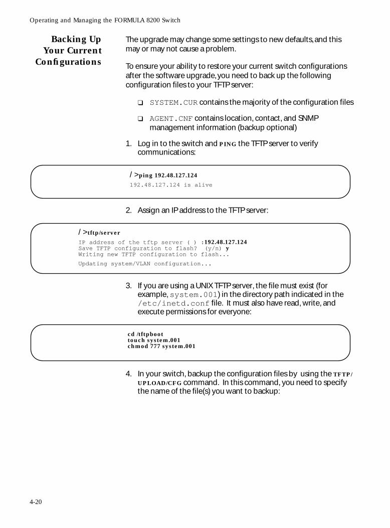
Operating and Managing the FORMULA 8200 Switch
Backing UpYour Current
Configurations
The upgrade may change some settings to new defaults, and this may or may not cause a problem.
To ensure your ability to restore your current switch configurations after the software upgrade, you need to back up the following configuration files to your TFTP server:
❑ SYSTEM.CUR contains the majority of the configuration files
❑ AGENT.CNF contains location, contact, and SNMP management information (backup optional)
1. Log in to the switch and PING the TFTP server to verify communications:
2. Assign an IP address to the TFTP server:
3. If you are using a UNIX TFTP server, the file must exist (for example, system.001) in the directory path indicated in the /etc/inetd.conf file. It must also have read, write, and execute permissions for everyone:
4. In your switch, backup the configuration files by using the TFTP/UPLOAD/CFG command. In this command, you need to specify the name of the file(s) you want to backup:
/ >ping 192.48.127.124
192.48.127.124 is alive
/ >tftp/server
IP address of the tftp server ( ) :192.48.127.124Save TFTP configuration to flash? (y/n) yWriting new TFTP configuration to flash...
Updating system/VLAN configuration...
cd /tftpboottouch system.001chmod 777 system.001
4-20
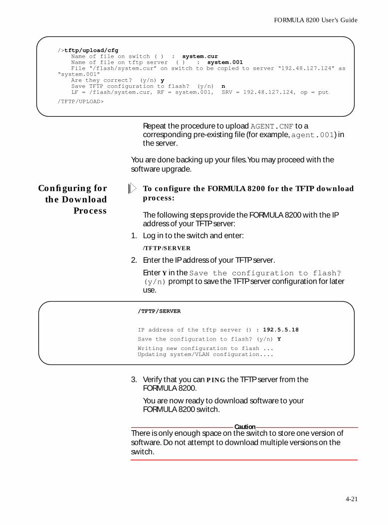
FORMULA 8200 User’s Guide
Repeat the procedure to upload AGENT.CNF to a corresponding pre-existing file (for example, agent.001) in the server.
You are done backing up your files. You may proceed with the software upgrade.
Configuring forthe Download
Process
To configure the FORMULA 8200 for the TFTP download process:
The following steps provide the FORMULA 8200 with the IP address of your TFTP server:
1. Log in to the switch and enter:
/TFTP/SERVER
2. Enter the IP address of your TFTP server.
Enter Y in the Save the configuration to flash? (y/n) prompt to save the TFTP server configuration for later use.
3. Verify that you can PING the TFTP server from the FORMULA 8200.
You are now ready to download software to your FORMULA 8200 switch.
CautionThere is only enough space on the switch to store one version of software. Do not attempt to download multiple versions on the switch.
/>tftp/upload/cfgName of file on switch ( ) : system.curName of file on tftp server ( ) : system.001File “/flash/system.cur” on switch to be copied to server “192.48.127.124” as
“system.001”Are they correct? (y/n) ySave TFTP configuration to flash? (y/n) nLF = /flash/system.cur, RF = system.001, SRV = 192.48.127.124, op = put
/TFTP/UPLOAD>
/TFTP/SERVER
IP address of the tftp server () : 192.5.5.18 Save the configuration to flash? (y/n) Y
Writing new configuration to flash ... Updating system/VLAN configuration....
4-21
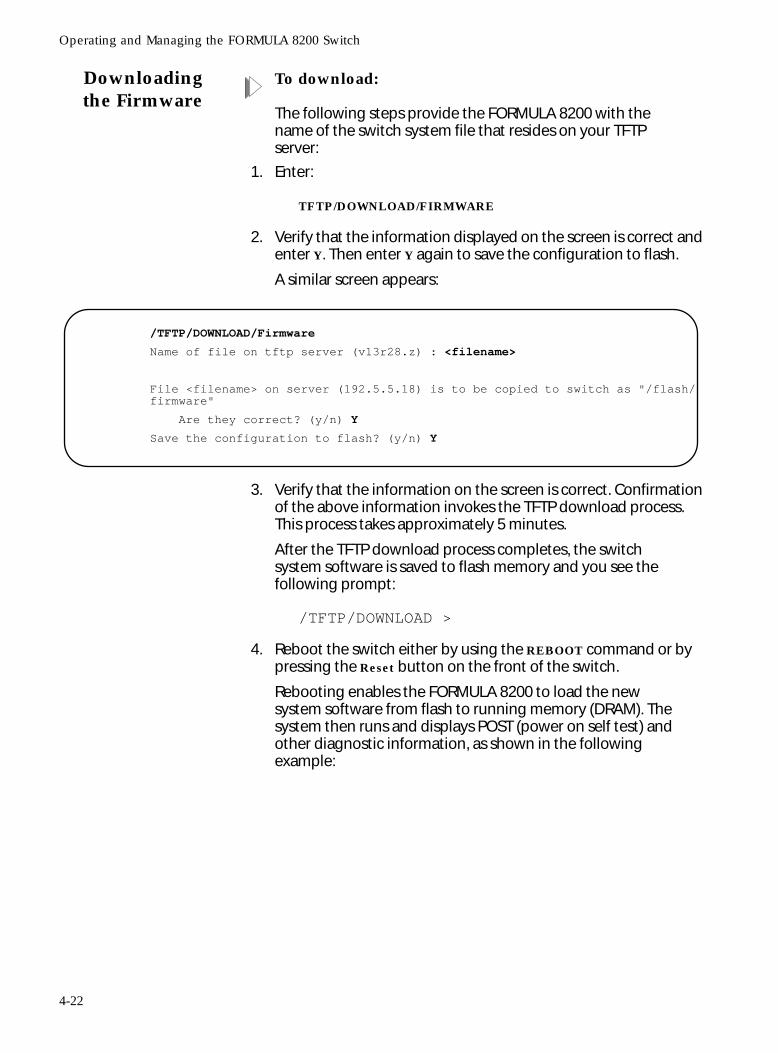
Operating and Managing the FORMULA 8200 Switch
Downloadingthe Firmware
To download:
The following steps provide the FORMULA 8200 with the name of the switch system file that resides on your TFTP server:
1. Enter:
TFTP/DOWNLOAD/FIRMWARE
2. Verify that the information displayed on the screen is correct and enter Y. Then enter Y again to save the configuration to flash.
A similar screen appears:
3. Verify that the information on the screen is correct. Confirmation of the above information invokes the TFTP download process. This process takes approximately 5 minutes.
After the TFTP download process completes, the switch system software is saved to flash memory and you see the following prompt:
/TFTP/DOWNLOAD >
4. Reboot the switch either by using the REBOOT command or by pressing the Reset button on the front of the switch.
Rebooting enables the FORMULA 8200 to load the new system software from flash to running memory (DRAM). The system then runs and displays POST (power on self test) and other diagnostic information, as shown in the following example:
/TFTP/DOWNLOAD/Firmware
Name of file on tftp server (v13r28.z) : <filename>
File <filename> on server (192.5.5.18) is to be copied to switch as "/flash/firmware"
Are they correct? (y/n) Y
Save the configuration to flash? (y/n) Y
4-22
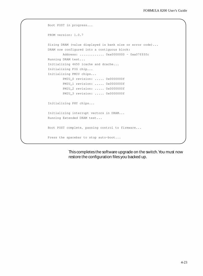
FORMULA 8200 User’s Guide
This completes the software upgrade on the switch. You must now restore the configuration files you backed up.
Boot POST in progress...
PROM version: 1.0.7
Sizing DRAM (value displayed is bank size or error code)...
DRAM now configured into a contiguous block:
Address: ............. 0xa0000000 - 0xa07ffffc
Running DRAM test...
Initializing 4650 icache and dcache...
Initializing PIG chip...
Initializing PMIU chips...
PMIU_0 revision: ..... 0x0000000f
PMIU_1 revision: ..... 0x0000000f
PMIU_2 revision: ..... 0x0000000f
PMIU_3 revision: ..... 0x0000000f
Initializing PHY chips...
Initializing interrupt vectors in DRAM...
Running Extended DRAM test...
Boot POST complete, passing control to firmware...
Press the spacebar to stop auto-boot...
4-23
Operating and Managing the FORMULA 8200 Switch
Restoring YourConfigurations
After making sure the software upgrade is stable, you may restore your old configurations using the following procedure.
To restore your configurations;
1. Log in to the switch and PING the TFTP server to verify communications:
2. Assign an IP address to the TFTP server:
3. Restore the configuration files by using the TFTP/DOWNLOAD//CFG command. In this command, you need to specify the name of the file(s) you want to restore:
4. Reboot the switch using the REBOOT command on the console prompt.
/ >ping 192.48.127.124
192.48.127.124 is alive
/ >tftp/server
IP address of the tftp server ( ) :192.48.127.124Save TFTP configuration to flash? (y/n) yWriting new TFTP configuration to flash...
Updating system/VLAN configuration...
/ >tftp/download/cfg
Name of file on switch (system.cur) :Name of file on tftp server (system.001) :
File “system.001” on server (192.48.12.124) is to be copied to switch as flash/system.cur”
Are they correct? (y/n) ySave TFTP configuration to flash? (y/n) y
Writing new TFTP configuration to flash ...Updating system/VLAN configuration
LF = /flash/system.cur, RF = system.001, SRV = 192.48.127.124, op = get
/TFTP/DOWNLOAD>
/ TFTP/DOWNLOAD>top/ >rebootAre you sure, you want to reboot ? [y/n]: y
4-24
FORMULA 8200 User’s Guide
In Case ofProblems With
the SoftwareUpgrade
This section tells you what to do if the software upgrade fails due to interruptions or if you see error messages while rebooting the switch as part of the upgrade process.
Interruptions during the download process
Interrupting a software download (for example, rebooting the switch or disconnecting the power cord) creates files of 0 bytes. Attempts to download again will not succeed because the download process cannot write over these files.
If you encounter these problems:
1. Log in to the switch.
2. Manually delete the firmware file by entering:
/FILE/DELETE firmware
3. Download the firmware again.
Error message during the boot process
If you see the following error message:
this means you can not use the CLI to download. Refer to Appendix C, Downloading Software at the [VxWorks] Prompt, for alternate procedures on how to download software to the FORMULA 8200.
error uncompressing file
status=0X3D00Q can’t load boot file.
4-25
Operating and Managing the FORMULA 8200 Switch
Displaying RIP Support Information
The FORMULA 8200 IP routing function is implemented on an individual-VLAN basis. When a VLAN is created, the FORMULA 8200 provides an option to configure its interface as an IP router and allows the network manager to choose from four RIP modes: active (send and receive RIP packets), deaf (send only), inactive (RIP disabled) or silent (receive only).
To display routes:
Use the INET/SHOW/ROUTE command.
/INET/SHOW/ROUTE
ROUTE NET TABLE:
Address ============
Gateway =============
Metric ======
VLAN =====
Type ==============
192.18.29.0 192.18.29.200 1 1 VLAN INTERFACE
192.18.30.0 192.18.30.200 1 2 VLAN INTERFACE
ROUTE HOST TABLE:
Address ============
Gateway =============
Metric ======
VLAN =====
Type ==============
132.10.10.1 192.18.29.200 2 1 STATIC
131.20.20.1 192.18.29.200 1 1 STATIC
193.10.10.1 192.18.29.200 1 1 STATIC
127.0.0.1 127.0.0.1 1 1 LOOPBACK
4-26
FORMULA 8200 User’s Guide
Modifying the IP RIP Mode
This section shows you how to modify the IP RIP mode once a VLAN has been created. You can set the RIP mode to one of four available states:
❑ Active (a) - to send and receive RIP packets
❑ Deaf (d) - to send only
❑ Inactive (i) - to disable RIP
❑ Silent (s) - to receive only
In the example below, the initial mode is silent and is modified to active. Use the same procedure to change the mode to any other state.
To modify the IP RIP mode:
1. Enter the VLAN/CONFIG/MODIFY <VLAN#> command.
The following display appears:
2. Set RIP mode to Active by entering the following at the prompt:
9=A
3. Confirm the change by entering 0 at the prompt:
Enter selection (0 to commit, c to cancel) >0
VLAN Modification :
VLAN 3 Configuration Parameters Current Value
------------------------------------------------------
1) VLAN ID :- 3
2) Description :- VLAN 3
3) VLAN enabled :- Y
4) IP enabled :- Y
5) Network Address : - 192.18.31.200
6) Subnetwork Mask :- 255.255.255.0
7) Broadcast Address : - 192.18.31.255
8) Router Description :- Router for VLAN 3
9) IP RIP Mode (Active(a), Silent(s), Deaf(d), Inactive(i)) : -
Silent
------------------------------------------------------
Modification instruction :
usage: <number of parameter> = <new vlaue>
command example: 2 = Engineering VLAN(#1)
---------------------------------------------
Enter selection (0 to commit, c to cancel) >
4-27
Operating and Managing the FORMULA 8200 Switch
Configuring Static Routes
To add static routes:
Use the INET/CONFIG/ROUTE/ADD command.
All static routes are saved into the FORMULA 8200 flash memory and downloaded at startup or system reset.
Deleting StaticRoutes
To delete a static route:
Use the INET/CONFIG/ROUTE/DELETE command:
/INET/CONFIG/ROUTE/ADD
Add static route -Host/network IP address: 132.10.10.1Gateway IP address: 192.18.29.200Metric: 2Add route? (yes) yUpdating system/VLAN configuration....Route has been added.
/INET/CONFIG/ROUTE/DELETE
Delete static route -Host/network IP address: 130.10.10.1Gateway IP address: 192.18.29.200Delete route? (yes) yUpdating system/VLAN configuration....Static route has been deleted.
4-28
FORMULA 8200 User’s Guide
Removing an IP Default Gateway
To remove an IP default gateway:
Use the INET/CONFIG/ROUTE/RMDEFAULT command.
Remove default route -
Gateway IP address: 192.18.29.200
Delete route? (yes) y
Route has been deleted.
Updating system/VLAN configuration....
Static route has been deleted from the flash.
Default route has been deleted.
/INET/CONFIG/ROUTE >VIR
ROUTE NET TABLE:
Address ============
Gateway =============
Metric ======
VLAN =====
Type ==============
192.18.29.0 192.18.29.200 1 1 VLAN INTERFACE
192.18.30.0 192.18.30.200 1 2 VLAN INTERFACE
ROUTE HOST TABLE:
Address ============
Gateway =============
Metric ======
VLAN =====
Type ==============
132.10.10.1 192.18.29.200 2 1 STATIC
131.20.20.1 192.18.29.200 1 1 STATIC
193.10.10.1 192.18.29.200 1 1 STATIC
127.0.0.1 127.0.0.1 1 1 LOOPBACK
4-29
Operating and Managing the FORMULA 8200 Switch
Configuring SNMP Parameters
You can configure the FORMULA 8200 to communicate with a network management station via SNMP (SNMP v.1 only). To configure the FORMULA 8200 as an SNMP managed networking device, you can provide system description, system contact, system location, and both read and write community strings.
To configure the FORMULA 8200 as an SNMP managed device:
1. Use the SNMP/CONFIG command to configure SNMP parameters as in the following screen:
2. Enter A to create a trap destination table and then respond to the prompts. For example:
— Enter 192.2.150.49 as the destination IP address.
— Press Enter to accept 162 as the default UDP port number.
— Enter public as the community string.
The screen displays the following similar information:
3. Enter q to quit and then y to save the information to flash as in the following example:
/SNMP/CONFIG
SNMP Agent configuration:
system contact () : JOE ADMIN
system location () : ENGINEERING LAB
Read community string (public) :
Write community string (private) :
SNMP trap destination table is empty.
Enter A=add, C=change, D=delete, Q=quit
SNMP Trap Destination Table
Enter A=add, C=change, D=delete, Q=Quit:
Index =====
IP Address ==========
UDP Port ==========
Community ==========
1. 192.2.150.49 162 public
Enter A=add, C=change, D=delete, Q=Quit: qOK to write SNMP config file (y/n)? y
4-30
FORMULA 8200 User’s Guide
Displaying SNMP Parameters
To display system description, location and contact:
1. Use the SNMP/SHOW/PARAM command:
2. Enter the information at the prompts.
To display the read community string:
Use the SNMP/SHOW/READCOMM command.
To display the write community string:
Use the SNMP/SHOW/WRITECOMM command.
/SNMP/SHOW/PARAM
System Description:
System location :
System contact :
4-31

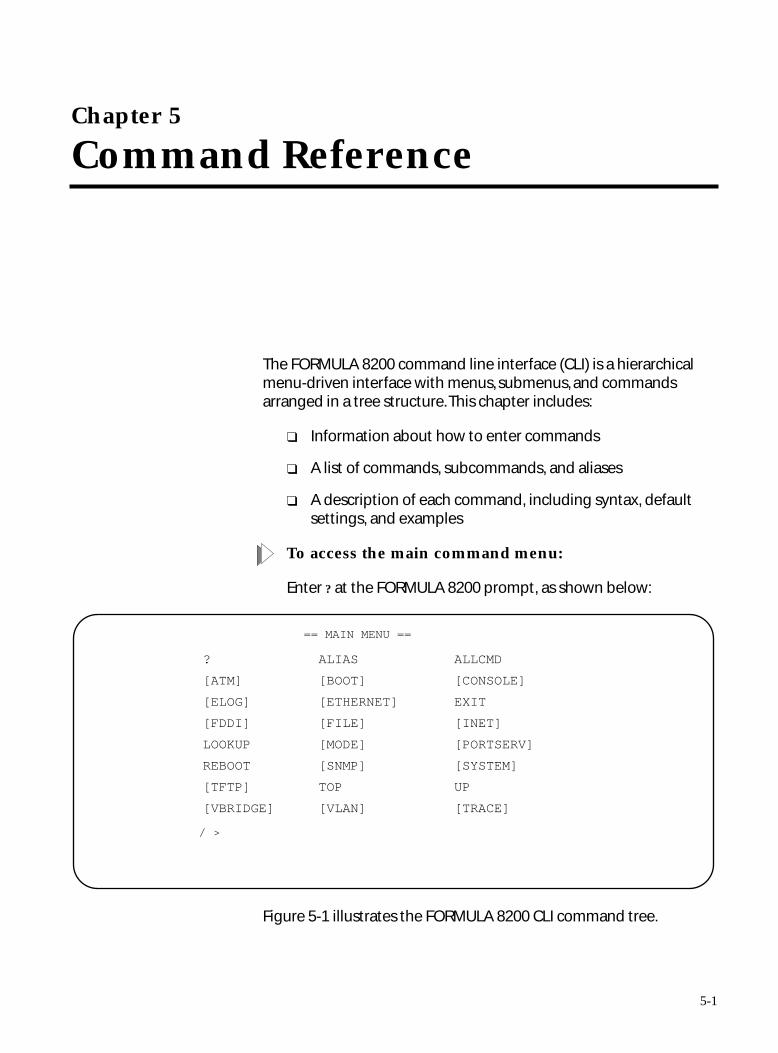
Chapter 5
Command Reference
The FORMULA 8200 command line interface (CLI) is a hierarchical menu-driven interface with menus, submenus, and commands arranged in a tree structure. This chapter includes:
❑ Information about how to enter commands
❑ A list of commands, subcommands, and aliases
❑ A description of each command, including syntax, default settings, and examples
To access the main command menu:
Enter ? at the FORMULA 8200 prompt, as shown below:
Figure 5-1 illustrates the FORMULA 8200 CLI command tree.
== MAIN MENU ==
/ >
? ALIAS ALLCMD
[ATM] [BOOT] [CONSOLE]
[ELOG] [ETHERNET] EXIT
[FDDI] [FILE] [INET]
LOOKUP [MODE] [PORTSERV]
REBOOT [SNMP] [SYSTEM]
[TFTP] TOP UP
[VBRIDGE] [VLAN] [TRACE]
5-1
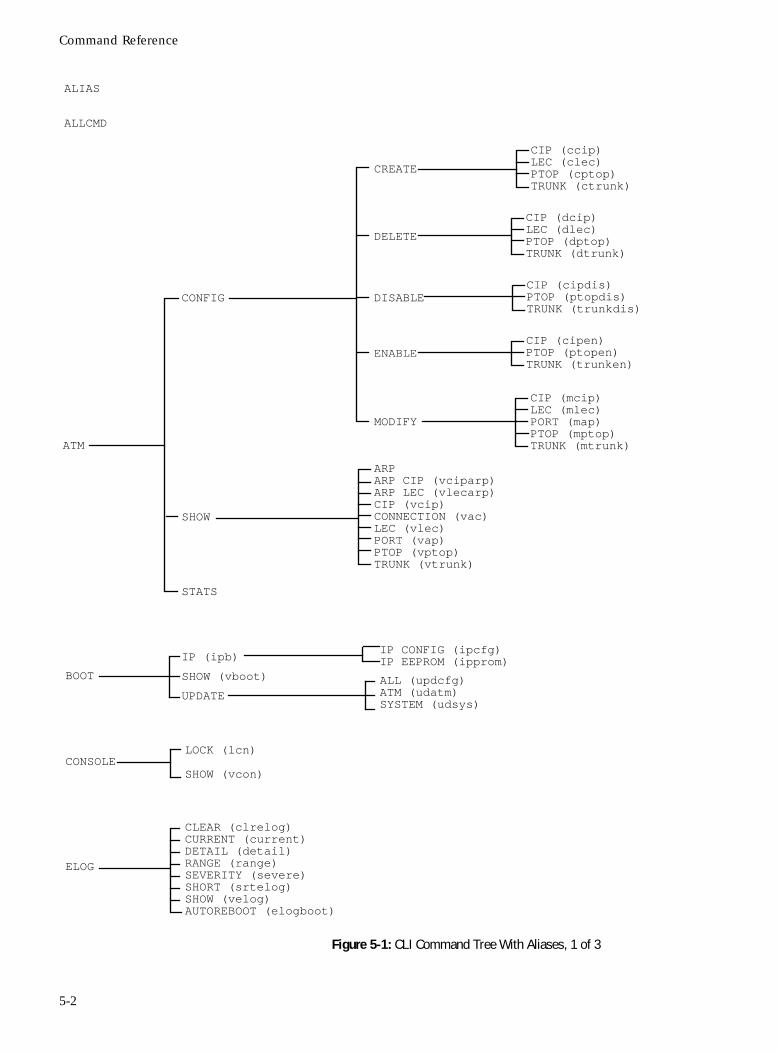
Command Reference
Figure 5-1: CLI Command Tree With Aliases, 1 of 3
BOOT
IP (ipb)
SHOW (vboot)
UPDATE
IP CONFIG (ipcfg)IP EEPROM (ipprom)
ALL (updcfg)ATM (udatm)SYSTEM (udsys)
CONSOLELOCK (lcn)
SHOW (vcon)
ELOG
CLEAR (clrelog)CURRENT (current)DETAIL (detail)RANGE (range)SEVERITY (severe)SHORT (srtelog)SHOW (velog)AUTOREBOOT (elogboot)
ALIAS
ALLCMD
CIP (ccip)LEC (clec)PTOP (cptop)TRUNK (ctrunk)
ATM
CONFIG
SHOW
ARPARP CIP (vciparp)ARP LEC (vlecarp)CIP (vcip)
CREATE
DELETE
CIP (dcip)LEC (dlec)PTOP (dptop)TRUNK (dtrunk)
DISABLECIP (cipdis)PTOP (ptopdis)TRUNK (trunkdis)
ENABLECIP (cipen)PTOP (ptopen)TRUNK (trunken)
MODIFY
CIP (mcip)LEC (mlec)PORT (map)PTOP (mptop)TRUNK (mtrunk)
CONNECTION (vac)LEC (vlec)PORT (vap)PTOP (vptop)TRUNK (vtrunk)
STATS
5-2
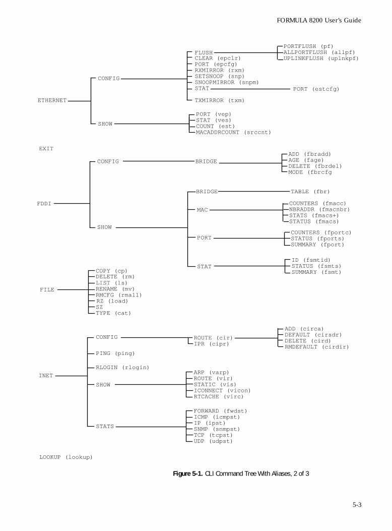
FORMULA 8200 User’s Guide
Figure 5-1. CLI Command Tree With Aliases, 2 of 3
FILE
COPY (cp)DELETE (rm)LIST (ls)RENAME (mv)RMCFG (rmall)
SZRZ (load)
TYPE (cat)
INET
CONFIG ROUTE (cir)
ADD (circa)DEFAULT (cirsdr)DELETE (cird)RMDEFAULT (cirdir)
PING (ping)
RLOGIN (rlogin)ARP (varp)ROUTE (vir)STATIC (vis)ICONNECT (vicon)
SHOW
FORWARD (fwdst)ICMP (icmpst)IP (ipst)
STATS SNMP (snmpst)TCP (tcpst)
IPR (cipr)
RTCACHE (virc)
FDDI
CONFIG
SHOW
BRIDGE
BRIDGE
MAC
TABLE (fbr)
COUNTERS (fmacc)NBRADDR (fmacnbr)STATS (fmacs+)STATUS (fmacs)
PORTCOUNTERS (fportc)STATUS (fports)SUMMARY (fport)
STATID (fsmtid)STATUS (fsmts)SUMMARY (fsmt)
ADD (fbradd)AGE (fage)DELETE (fbrdel)MODE (fbrcfg
EXIT
ETHERNET
CONFIG
SHOW
CLEAR (epclr)PORT (epcfg)RXMIRROR (rxm)SETSNOOP (snp)SNOOPMIRROR (snpm)STAT
PORT (vep)STAT (ves)
PORT (estcfg)
TXMIRROR (txm)
COUNT (est)MACADDRCOUNT (srccnt)
FLUSHPORTFLUSH (pf)ALLPORTFLUSH (allpf)UPLINKFLUSH (uplnkpf)
LOOKUP (lookup)
UDP (udpst)
5-3
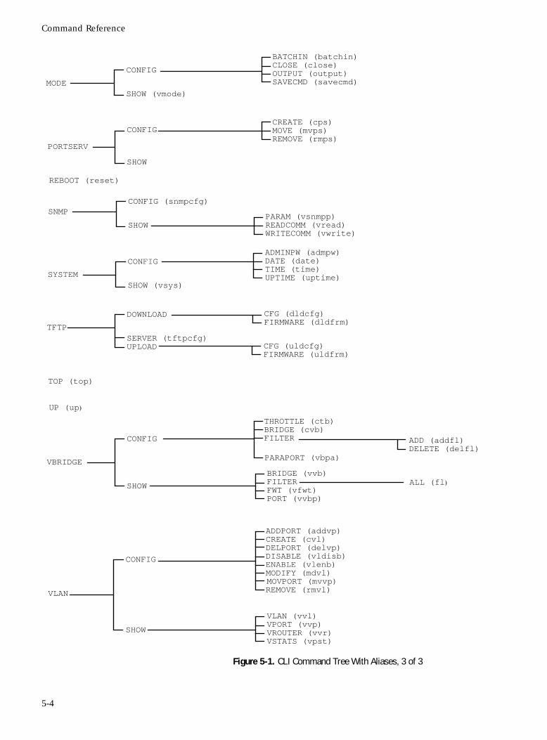
Command Reference
Figure 5-1. CLI Command Tree With Aliases, 3 of 3
ADDPORT (addvp)CREATE (cvl)DELPORT (delvp)DISABLE (vldisb)ENABLE (vlenb)MODIFY (mdvl)
REMOVE (rmvl)MOVPORT (mvvp)
TOP (top)
VLAN
BRIDGE (vvb)FILTERFWT (vfwt)PORT (vvbp)
UP (up)
VBRIDGE
CONFIG
THROTTLE (ctb)BRIDGE (cvb)
SHOW
PARAPORT (vbpa)
ADD (addfl)DELETE (delfl)
CONFIG
SHOW
FILTER
VLAN (vvl)VPORT (vvp)VROUTER (vvr)VSTATS (vpst)
ALL (fl)
REBOOT (reset)
SNMPCONFIG (snmpcfg)
SHOWPARAM (vsnmpp)READCOMM (vread)WRITECOMM (vwrite)
SYSTEM
CONFIG
SHOW (vsys)
ADMINPW (admpw)DATE (date)TIME (time)
TFTP
DOWNLOAD
SERVER (tftpcfg)
CFG (dldcfg)FIRMWARE (dldfrm)
UPLOAD CFG (uldcfg)FIRMWARE (uldfrm)
PORTSERV
CONFIG
SHOW
MODE
CONFIG
SHOW (vmode)
BATCHIN (batchin)CLOSE (close)OUTPUT (output)SAVECMD (savecmd)
CREATE (cps)MOVE (mvps)REMOVE (rmps)
UPTIME (uptime)
5-4
FORMULA 8200 User’s Guide
ATM and FDDI Support
The ATM and FDDI commands in this chapter are enabled if you have the appropriate card installed in the uplink slot: the AT-8202 for ATM or the AT-8203 for FDDI connectivity.
For details about ATM commands, refer to the AT-8202 ATM Uplink User’s Guide. For details about FDDI commands, refer to the AT-8203 FDDI Uplink User’s Guide. These guides are available in PDF format from Allied Telesyn website at www.alliedtelesyn.com/manuals.htm.
5-5
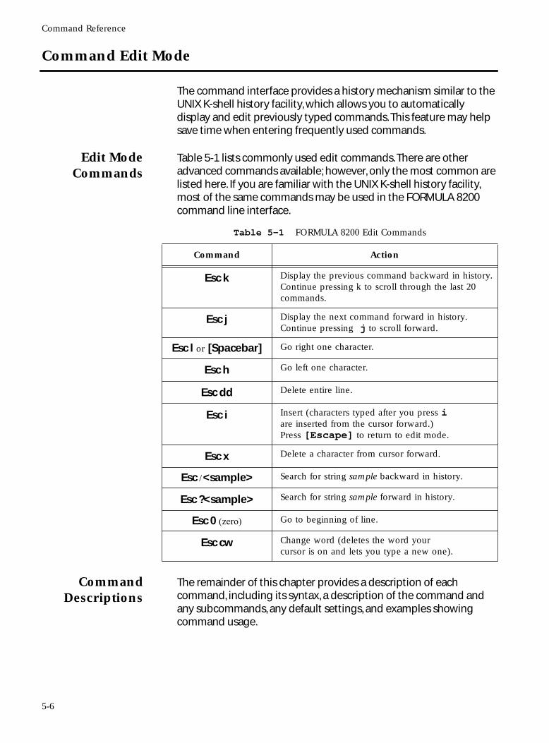
Command Reference
Command Edit Mode
The command interface provides a history mechanism similar to the UNIX K-shell history facility, which allows you to automatically display and edit previously typed commands. This feature may help save time when entering frequently used commands.
Edit ModeCommands
Table 5-1 lists commonly used edit commands. There are other advanced commands available; however, only the most common are listed here. If you are familiar with the UNIX K-shell history facility, most of the same commands may be used in the FORMULA 8200 command line interface.
CommandDescriptions
The remainder of this chapter provides a description of each command, including its syntax, a description of the command and any subcommands, any default settings, and examples showing command usage.
Table 5-1 FORMULA 8200 Edit Commands
Command Action
Esc k Display the previous command backward in history. Continue pressing k to scroll through the last 20 commands.
Esc j Display the next command forward in history. Continue pressing j to scroll forward.
Esc l or [Spacebar] Go right one character.
Esc h Go left one character.
Esc dd Delete entire line.
Esc i Insert (characters typed after you press i are inserted from the cursor forward.) Press [Escape] to return to edit mode.
Esc x Delete a character from cursor forward.
Esc /<sample> Search for string sample backward in history.
Esc ?<sample> Search for string sample forward in history.
Esc 0 (zero) Go to beginning of line.
Esc cw Change word (deletes the word your cursor is on and lets you type a new one).
5-6
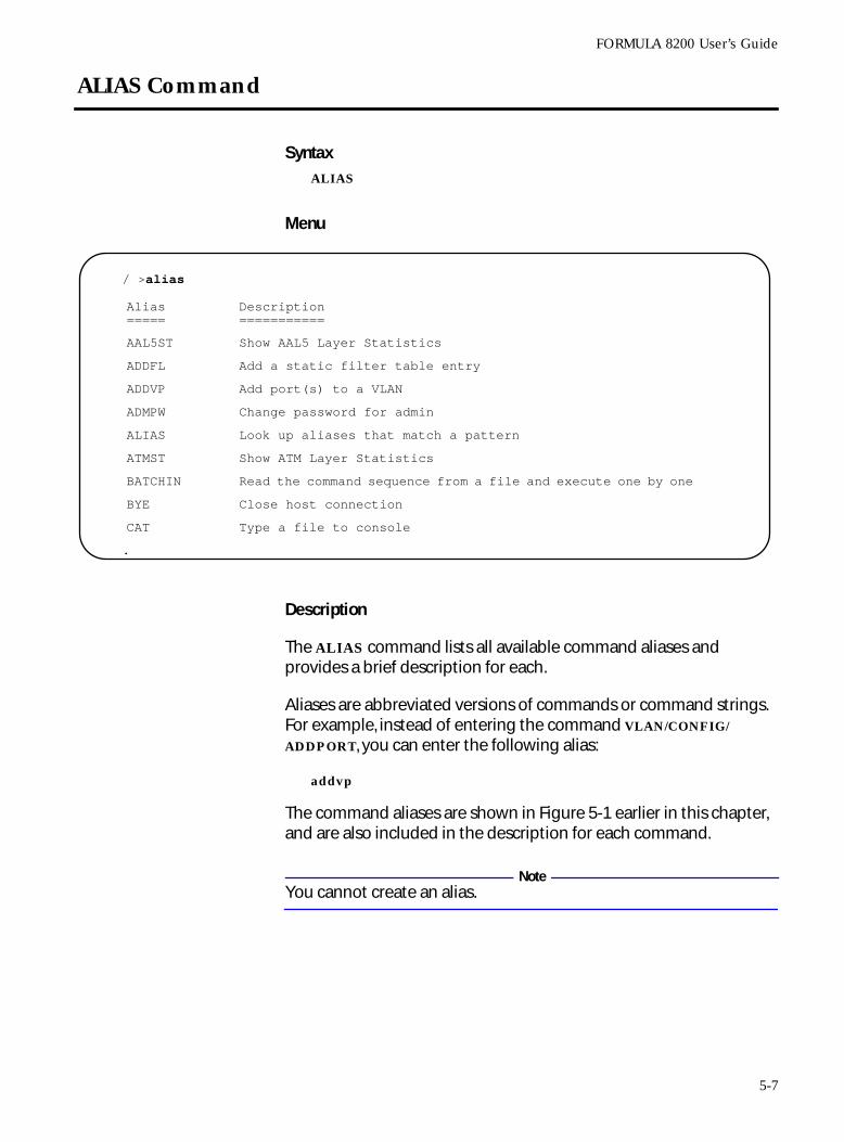
FORMULA 8200 User’s Guide
ALIAS Command
SyntaxALIAS
Menu
Description
The ALIAS command lists all available command aliases and provides a brief description for each.
Aliases are abbreviated versions of commands or command strings. For example, instead of entering the command VLAN/CONFIG/
ADDPORT, you can enter the following alias:
addvp
The command aliases are shown in Figure 5-1 earlier in this chapter, and are also included in the description for each command.
NoteYou cannot create an alias.
/ >alias
.
Alias=====
Description===========
AAL5ST Show AAL5 Layer Statistics
ADDFL Add a static filter table entry
ADDVP Add port(s) to a VLAN
ADMPW Change password for admin
ALIAS Look up aliases that match a pattern
ATMST Show ATM Layer Statistics
BATCHIN Read the command sequence from a file and execute one by one
BYE Close host connection
CAT Type a file to console
5-7
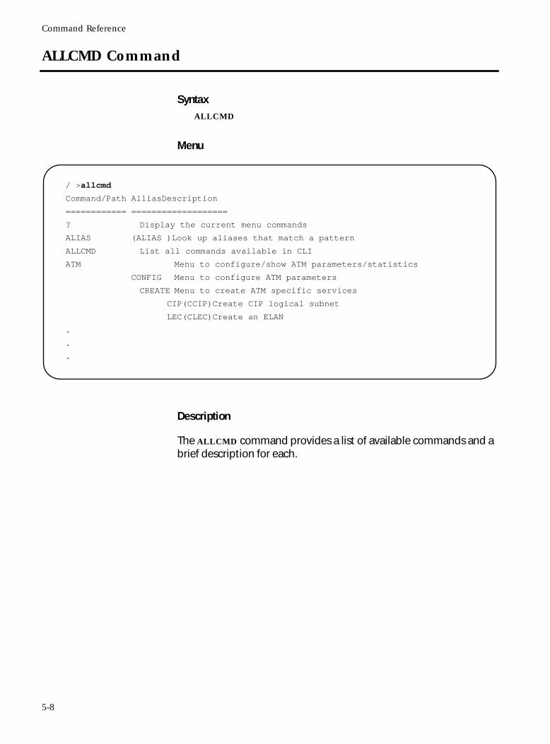
Command Reference
ALLCMD Command
SyntaxALLCMD
Menu
Description
The ALLCMD command provides a list of available commands and a brief description for each.
/ >allcmd
Command/Path AlliasDescription
============ ===================
? Display the current menu commands
ALIAS (ALIAS )Look up aliases that match a pattern
ALLCMD List all commands available in CLI
ATM Menu to configure/show ATM parameters/statistics
CONFIG Menu to configure ATM parameters
CREATE Menu to create ATM specific services
CIP(CCIP)Create CIP logical subnet
LEC(CLEC)Create an ELAN
.
.
.
5-8
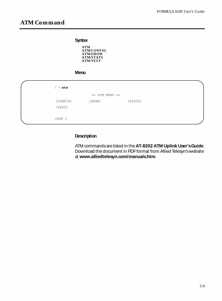
FORMULA 8200 User’s Guide
ATM Command
SyntaxATMATM/CONFIGATM/SHOWATM/STATSATM/TEST
Menu
Description
ATM commands are listed in the AT-8202 ATM Uplink User’s Guide. Download the document in PDF format from Allied Telesyn’s website at www.alliedtelesyn.com/manuals.htm.
/ > atm
/ATM >
== ATM MENU ==
[CONFIG] [SHOW] [STATS]
[TEST]
5-9
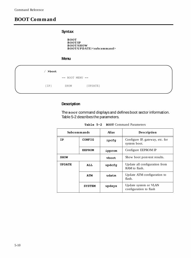
Command Reference
BOOT Command
Syntax
BOOTBOOT/IPBOOT/SHOWBOOT/UPDATE/<subcommand>
Menu
Description
The BOOT command displays and defines boot sector information. Table 5-2 describes the parameters.
/ >boot
== BOOT MENU ==
[IP] SHOW [UPDATE]
Table 5-2 BOOT Command Parameters
Subcommands Alias Description
IP CONFIG ipcfg Configure IP, gateway, etc. for system boot.
EEPROM ipprom Configure EEPROM IP
SHOW vboot Show boot post-test results.
UPDATE ALL updcfg Update all configuration from RAM to flash.
ATM udatm Update ATM configuration to flash.
SYSTEM updsys Update system or VLAN configuration to flash
5-10
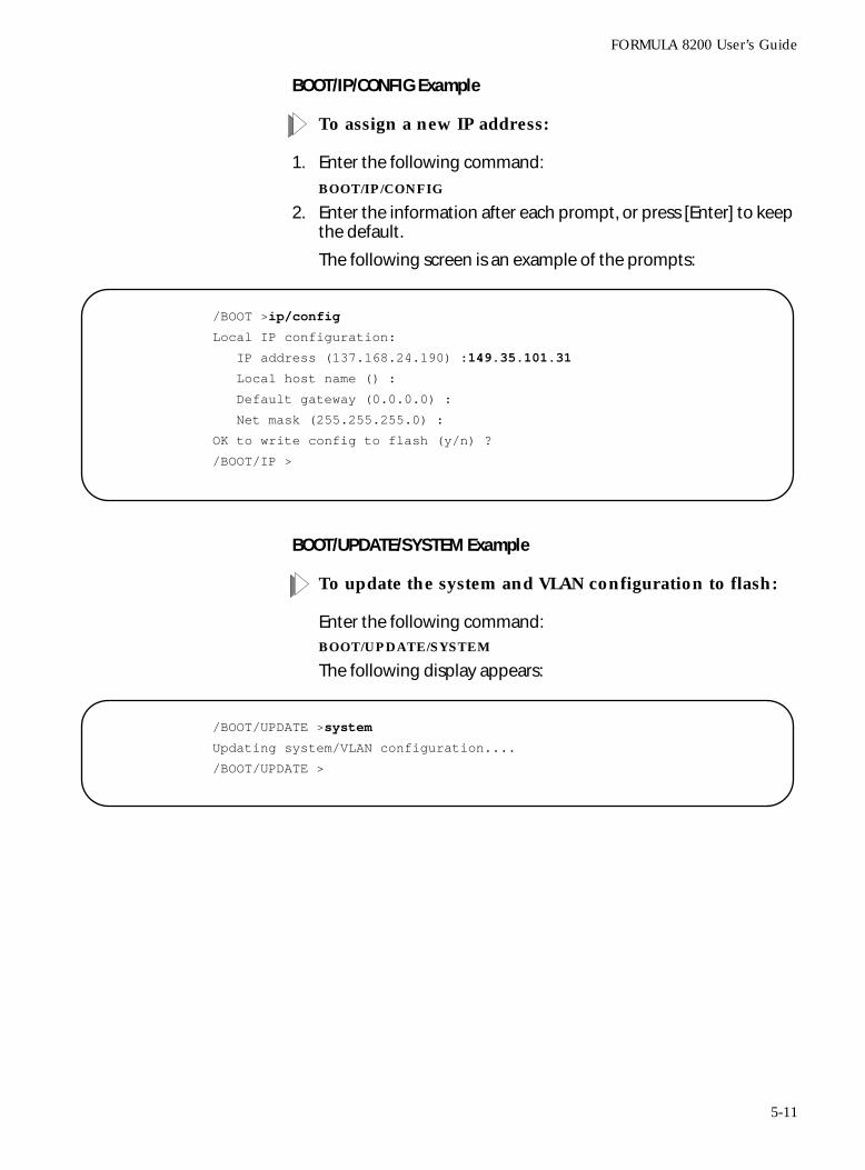
FORMULA 8200 User’s Guide
BOOT/IP/CONFIG Example
To assign a new IP address:
1. Enter the following command:
BOOT/IP/CONFIG
2. Enter the information after each prompt, or press [Enter] to keep the default.
The following screen is an example of the prompts:
BOOT/UPDATE/SYSTEM Example
To update the system and VLAN configuration to flash:
Enter the following command:BOOT/UPDATE/SYSTEM
The following display appears:
/BOOT >ip/config
Local IP configuration:
IP address (137.168.24.190) :149.35.101.31
Local host name () :
Default gateway (0.0.0.0) :
Net mask (255.255.255.0) :
OK to write config to flash (y/n) ?
/BOOT/IP >
/BOOT/UPDATE >system
Updating system/VLAN configuration....
/BOOT/UPDATE >
5-11
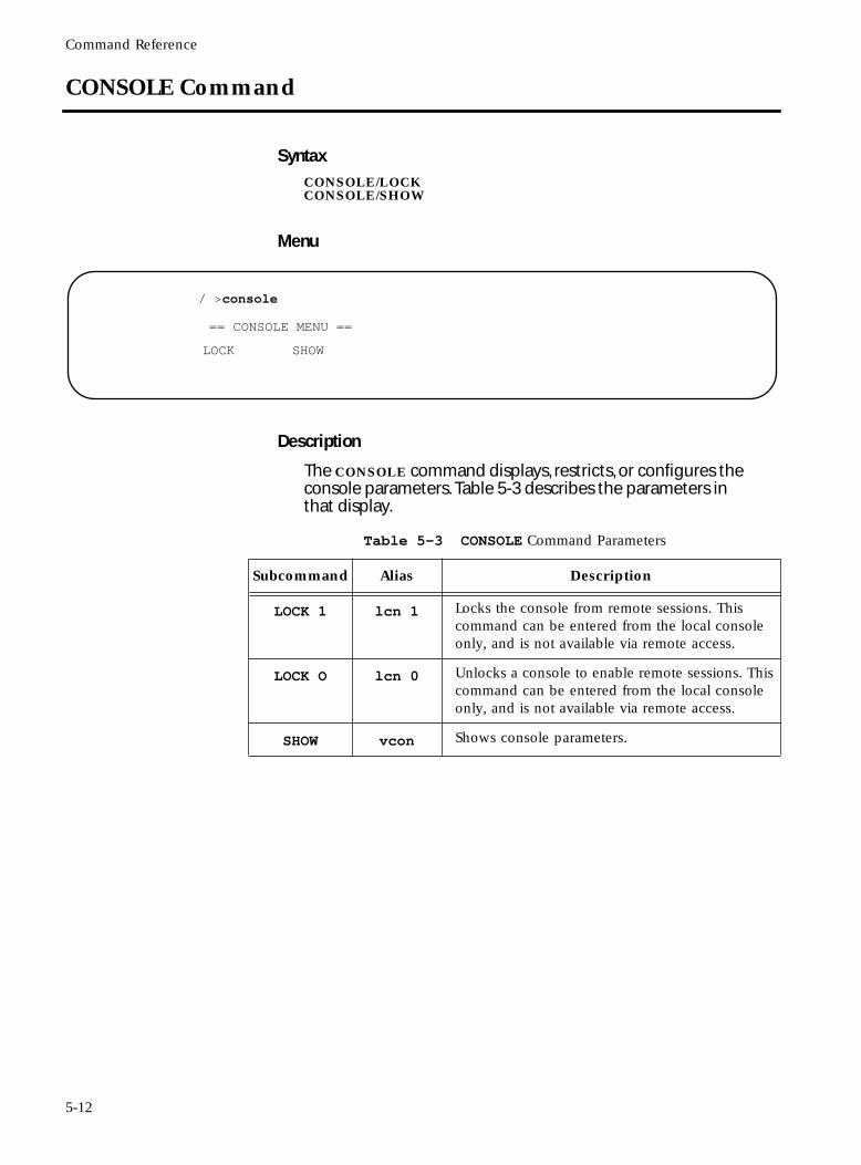
Command Reference
CONSOLE Command
SyntaxCONSOLE/LOCKCONSOLE/SHOW
Menu
Description
The CONSOLE command displays, restricts, or configures the console parameters. Table 5-3 describes the parameters in that display.
/ >console
== CONSOLE MENU ==
LOCK SHOW
Table 5-3 CONSOLE Command Parameters
Subcommand Alias Description
LOCK 1 lcn 1 Locks the console from remote sessions. This command can be entered from the local console only, and is not available via remote access.
LOCK O lcn 0 Unlocks a console to enable remote sessions. This command can be entered from the local console only, and is not available via remote access.
SHOW vcon Shows console parameters.
5-12
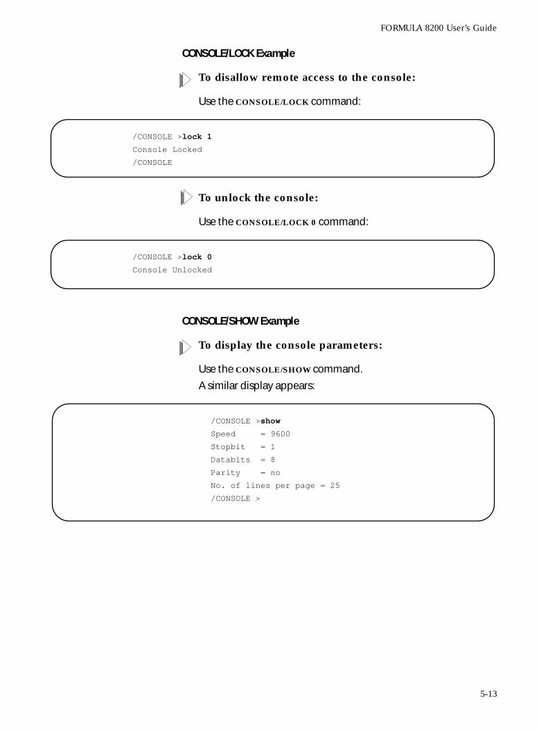
FORMULA 8200 User’s Guide
CONSOLE/LOCK Example
To disallow remote access to the console:
Use the CONSOLE/LOCK command:
To unlock the console:
Use the CONSOLE/LOCK 0 command:
CONSOLE/SHOW Example
To display the console parameters:
Use the CONSOLE/SHOW command.
A similar display appears:
/CONSOLE >lock 1
Console Locked
/CONSOLE
/CONSOLE >lock 0
Console Unlocked
/CONSOLE >show
Speed = 9600
Stopbit = 1
Databits = 8
Parity = no
No. of lines per page = 25
/CONSOLE >
5-13
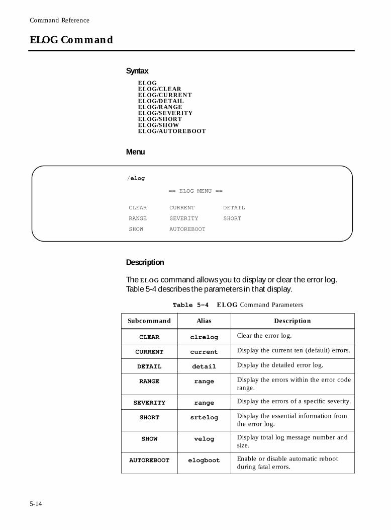
Command Reference
ELOG Command
SyntaxELOGELOG/CLEARELOG/CURRENTELOG/DETAILELOG/RANGEELOG/SEVERITYELOG/SHORTELOG/SHOWELOG/AUTOREBOOT
Menu
Description
The ELOG command allows you to display or clear the error log. Table 5-4 describes the parameters in that display.
/elog
== ELOG MENU ==
CLEAR CURRENT DETAIL
RANGE SEVERITY SHORT
SHOW AUTOREBOOT
Table 5-4 ELOG Command Parameters
Subcommand Alias Description
CLEAR clrelog Clear the error log.
CURRENT current Display the current ten (default) errors.
DETAIL detail Display the detailed error log.
RANGE range Display the errors within the error code range.
SEVERITY range Display the errors of a specific severity.
SHORT srtelog Display the essential information from the error log.
SHOW velog Display total log message number and size.
AUTOREBOOT elogboot Enable or disable automatic reboot during fatal errors.
5-14
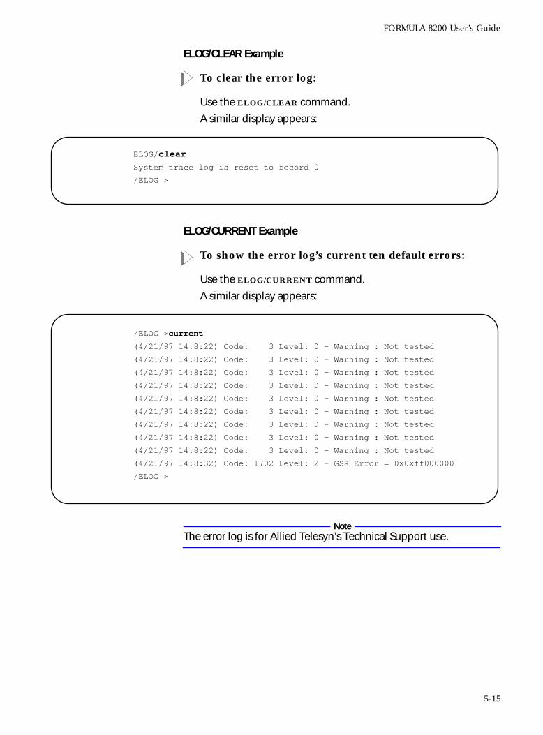
FORMULA 8200 User’s Guide
ELOG/CLEAR Example
To clear the error log:
Use the ELOG/CLEAR command.
A similar display appears:
ELOG/CURRENT Example
To show the error log’s current ten default errors:
Use the ELOG/CURRENT command.
A similar display appears:
NoteThe error log is for Allied Telesyn’s Technical Support use.
ELOG/clear
System trace log is reset to record 0
/ELOG >
/ELOG >current
(4/21/97 14:8:22) Code: 3 Level: 0 - Warning : Not tested
(4/21/97 14:8:22) Code: 3 Level: 0 - Warning : Not tested
(4/21/97 14:8:22) Code: 3 Level: 0 - Warning : Not tested
(4/21/97 14:8:22) Code: 3 Level: 0 - Warning : Not tested
(4/21/97 14:8:22) Code: 3 Level: 0 - Warning : Not tested
(4/21/97 14:8:22) Code: 3 Level: 0 - Warning : Not tested
(4/21/97 14:8:22) Code: 3 Level: 0 - Warning : Not tested
(4/21/97 14:8:22) Code: 3 Level: 0 - Warning : Not tested
(4/21/97 14:8:22) Code: 3 Level: 0 - Warning : Not tested
(4/21/97 14:8:32) Code: 1702 Level: 2 - GSR Error = 0x0xff000000
/ELOG >
5-15
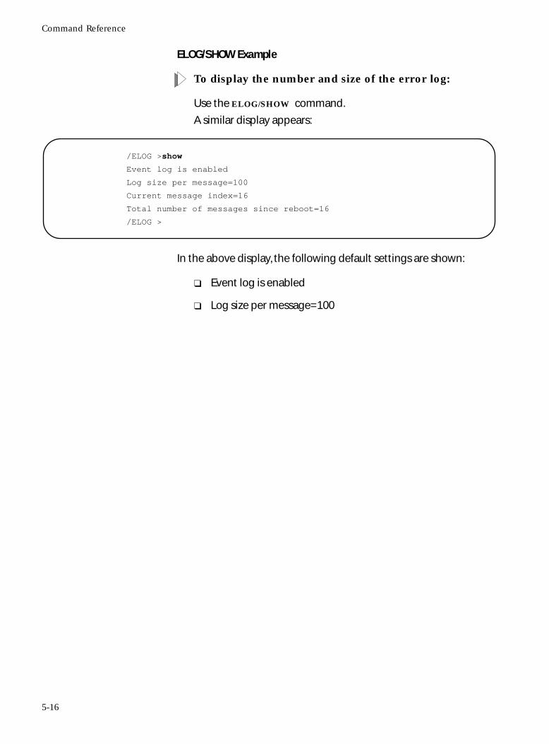
Command Reference
ELOG/SHOW Example
To display the number and size of the error log:
Use the ELOG/SHOW command.
A similar display appears:
In the above display, the following default settings are shown:
❑ Event log is enabled
❑ Log size per message=100
/ELOG >show
Event log is enabled
Log size per message=100
Current message index=16
Total number of messages since reboot=16
/ELOG >
5-16
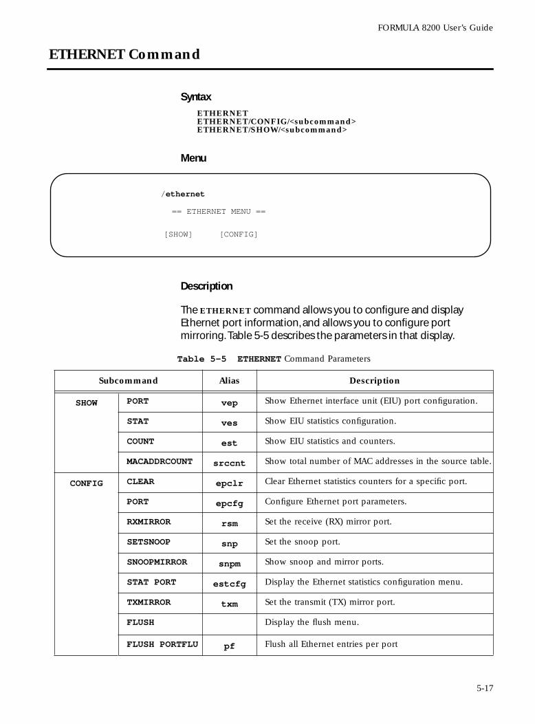
FORMULA 8200 User’s Guide
ETHERNET Command
SyntaxETHERNETETHERNET/CONFIG/<subcommand>ETHERNET/SHOW/<subcommand>
Menu
Description
The ETHERNET command allows you to configure and display Ethernet port information, and allows you to configure port mirroring. Table 5-5 describes the parameters in that display.
/ethernet
== ETHERNET MENU ==
[SHOW] [CONFIG]
Table 5-5 ETHERNET Command Parameters
Subcommand Alias Description
SHOW PORT vep Show Ethernet interface unit (EIU) port configuration.
STAT ves Show EIU statistics configuration.
COUNT est Show EIU statistics and counters.
MACADDRCOUNT srccnt Show total number of MAC addresses in the source table.
CONFIG CLEAR epclr Clear Ethernet statistics counters for a specific port.
PORT epcfg Configure Ethernet port parameters.
RXMIRROR rsm Set the receive (RX) mirror port.
SETSNOOP snp Set the snoop port.
SNOOPMIRROR snpm Show snoop and mirror ports.
STAT PORT estcfg Display the Ethernet statistics configuration menu.
TXMIRROR txm Set the transmit (TX) mirror port.
FLUSH Display the flush menu.
FLUSH PORTFLU pf Flush all Ethernet entries per port
5-17
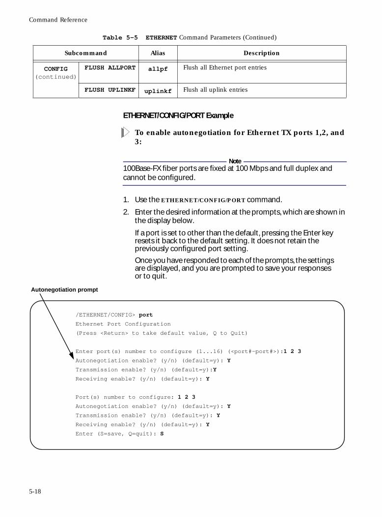
Command Reference
ETHERNET/CONFIG/PORT Example
To enable autonegotiation for Ethernet TX ports 1,2, and 3:
Note100Base-FX fiber ports are fixed at 100 Mbps and full duplex and cannot be configured.
1. Use the ETHERNET/CONFIG/PORT command.
2. Enter the desired information at the prompts, which are shown in the display below.
If a port is set to other than the default, pressing the Enter key resets it back to the default setting. It does not retain the previously configured port setting.
Once you have responded to each of the prompts, the settings are displayed, and you are prompted to save your responses or to quit.
CONFIG(continued)
FLUSH ALLPORT allpf Flush all Ethernet port entries
FLUSH UPLINKF uplinkf Flush all uplink entries
Table 5-5 ETHERNET Command Parameters (Continued)
Subcommand Alias Description
/ETHERNET/CONFIG> port
Ethernet Port Configuration
(Press <Return> to take default value, Q to Quit)
Enter port(s) number to configure (1...16) (<port#-port#>):1 2 3
Autonegotiation enable? (y/n) (default=y): Y
Transmission enable? (y/n) (default=y):Y
Receiving enable? (y/n) (default=y): Y
Port(s) number to configure: 1 2 3
Autonegotiation enable? (y/n) (default=y): Y
Transmission enable? (y/n) (default=y): Y
Receiving enable? (y/n) (default=y): Y
Enter (S=save, Q=quit): S
Autonegotiation prompt
5-18
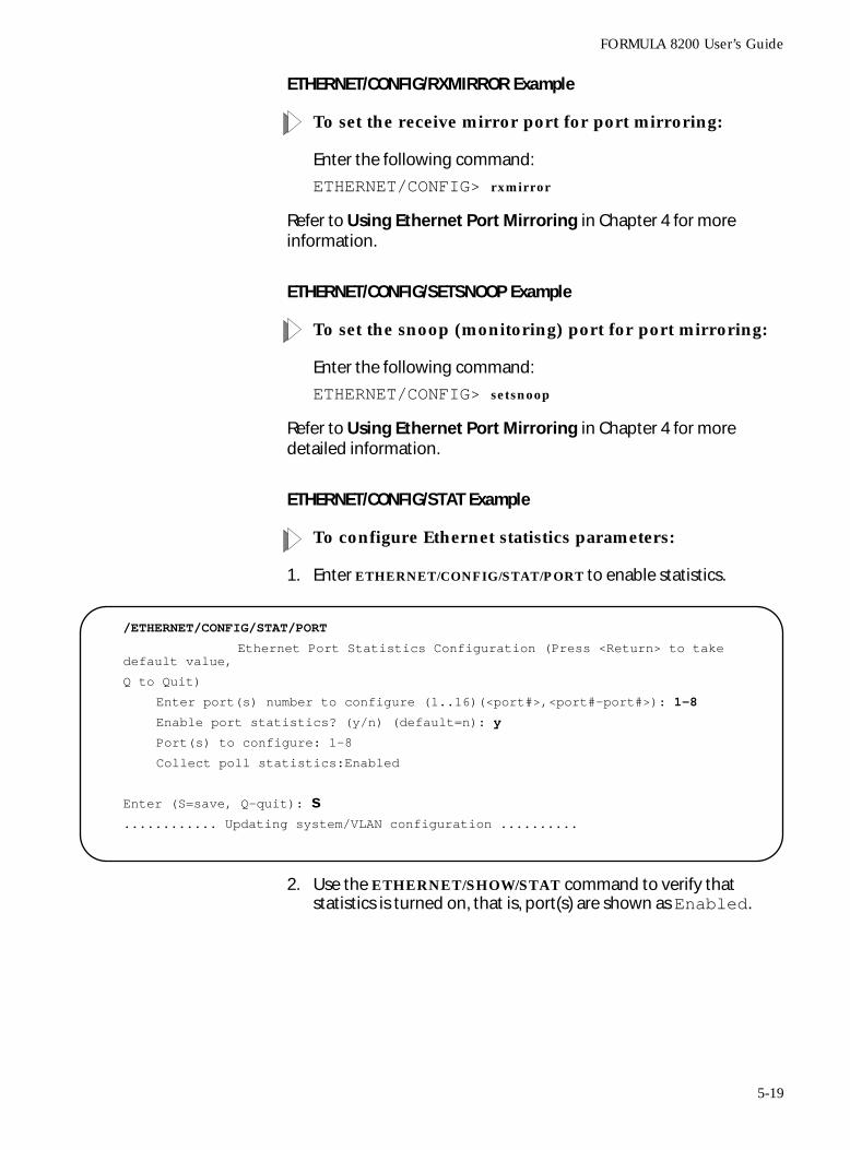
FORMULA 8200 User’s Guide
ETHERNET/CONFIG/RXMIRROR Example
To set the receive mirror port for port mirroring:
Enter the following command:
ETHERNET/CONFIG> rxmirror
Refer to Using Ethernet Port Mirroring in Chapter 4 for more information.
ETHERNET/CONFIG/SETSNOOP Example
To set the snoop (monitoring) port for port mirroring:
Enter the following command:
ETHERNET/CONFIG> setsnoop
Refer to Using Ethernet Port Mirroring in Chapter 4 for more detailed information.
ETHERNET/CONFIG/STAT Example
To configure Ethernet statistics parameters:
1. Enter ETHERNET/CONFIG/STAT/PORT to enable statistics.
2. Use the ETHERNET/SHOW/STAT command to verify that statistics is turned on, that is, port(s) are shown as Enabled.
/ETHERNET/CONFIG/STAT/PORT
Ethernet Port Statistics Configuration (Press <Return> to take default value,
Q to Quit)
Enter port(s) number to configure (1..16)(<port#>,<port#-port#>): 1-8
Enable port statistics? (y/n) (default=n): y
Port(s) to configure: 1-8
Collect poll statistics:Enabled
Enter (S=save, Q-quit): s............ Updating system/VLAN configuration ..........
5-19
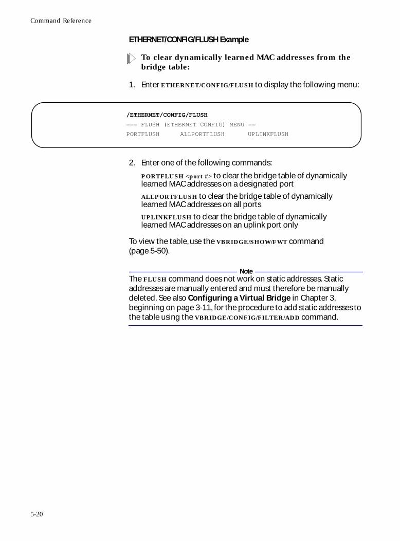
Command Reference
ETHERNET/CONFIG/FLUSH Example
To clear dynamically learned MAC addresses from the bridge table:
1. Enter ETHERNET/CONFIG/FLUSH to display the following menu:
2. Enter one of the following commands:
PORTFLUSH <port #> to clear the bridge table of dynamically learned MAC addresses on a designated port
ALLPORTFLUSH to clear the bridge table of dynamically learned MAC addresses on all ports
UPLINKFLUSH to clear the bridge table of dynamically learned MAC addresses on an uplink port only
To view the table, use the VBRIDGE/SHOW/FWT command (page 5-50).
NoteThe FLUSH command does not work on static addresses. Static addresses are manually entered and must therefore be manually deleted. See also Configuring a Virtual Bridge in Chapter 3, beginning on page 3-11, for the procedure to add static addresses to the table using the VBRIDGE/CONFIG/FILTER/ADD command.
/ETHERNET/CONFIG/FLUSH
=== FLUSH (ETHERNET CONFIG) MENU ==
PORTFLUSH ALLPORTFLUSH UPLINKFLUSH
5-20
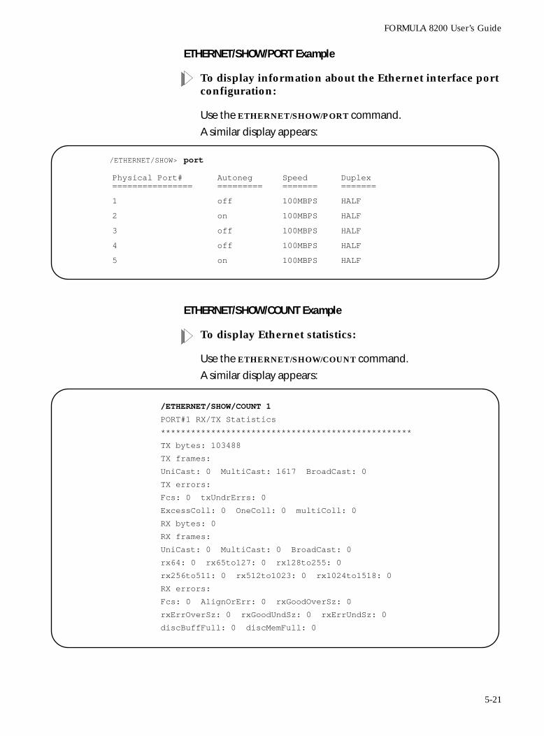
FORMULA 8200 User’s Guide
ETHERNET/SHOW/PORT Example
To display information about the Ethernet interface port configuration:
Use the ETHERNET/SHOW/PORT command.
A similar display appears:
ETHERNET/SHOW/COUNT Example
To display Ethernet statistics:
Use the ETHERNET/SHOW/COUNT command.
A similar display appears:
/ETHERNET/SHOW> port
Physical Port#================
Autoneg=========
Speed=======
Duplex=======
1 off 100MBPS HALF
2 on 100MBPS HALF
3 off 100MBPS HALF
4 off 100MBPS HALF
5 on 100MBPS HALF
/ETHERNET/SHOW/COUNT 1
PORT#1 RX/TX Statistics
**************************************************
TX bytes: 103488
TX frames:
UniCast: 0 MultiCast: 1617 BroadCast: 0
TX errors:
Fcs: 0 txUndrErrs: 0
ExcessColl: 0 OneColl: 0 multiColl: 0
RX bytes: 0
RX frames:
UniCast: 0 MultiCast: 0 BroadCast: 0
rx64: 0 rx65to127: 0 rx128to255: 0
rx256to511: 0 rx512to1023: 0 rx1024to1518: 0
RX errors:
Fcs: 0 AlignOrErr: 0 rxGoodOverSz: 0
rxErrOverSz: 0 rxGoodUndSz: 0 rxErrUndSz: 0
discBuffFull: 0 discMemFull: 0
5-21

Command Reference
Table 5-6 describes the parameters shown in the ETHERNET/SHOW/COUNT display.
Table 5-6 ETHERNET/SHOW/COUNT Parameters
Parameter Description
TX bytes The number of transmitted bytes since the last time Ethernet statistics were enabled or cleared
Tx frames UniCast The number of unicast frames transmitted from one network device to another single network device
MultiCast The number of multicast frames transmitted from one network device to multiple network devices
BroadCast The number of broadcast frames transmitted to all network devices
TX errors Fcs The number of frames that were discarded on the transmit side because of FCS (Frame Check Sequence) error
txUndrErrs The number of frames that were discarded on the transmit side because of underrun
ExcessColl The number of frames that were dropped because of excessive collisions
OneColl The number of frames that were transmitted after exactly one collision
multiColl The number of frames that were transmitted after more than one collision
Rx bytes The number of received bytes since the last time Ethernet statistics were enabled or cleared
RX frames
UniCast The number of received unicast frames
MultiCast The number of received multicast frames
BroadCast The number of received broadcast frames
rx64 The number of frames (including frames with errors) that were 64 bytes in length
rx65to127 The number of frames (including frames with errors) that were between 65 and 127 bytes long
rx128to255 The number of frames (including frames with errors) that were between 127 and 255 bytes long
rx256to511 The number of frames (including frames with errors) that were between 256 and 511 bytes long
rx512to1023 The number of frames (including frames with errors) that were between 512 and 1023 bytes long
rx1024to1518 The number of frames (including frames with errors) that were between 1024 and 1518 bytes long
5-22
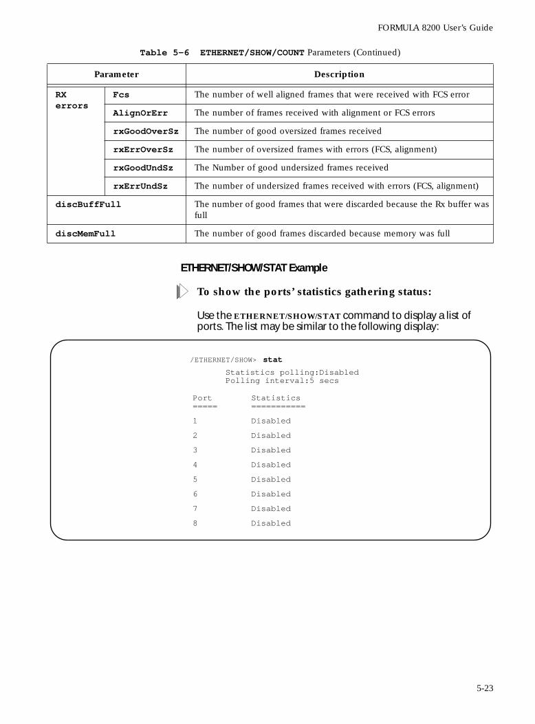
FORMULA 8200 User’s Guide
ETHERNET/SHOW/STAT Example
To show the ports’ statistics gathering status:
Use the ETHERNET/SHOW/STAT command to display a list of ports. The list may be similar to the following display:
RX errors
Fcs The number of well aligned frames that were received with FCS error
AlignOrErr The number of frames received with alignment or FCS errors
rxGoodOverSz The number of good oversized frames received
rxErrOverSz The number of oversized frames with errors (FCS, alignment)
rxGoodUndSz The Number of good undersized frames received
rxErrUndSz The number of undersized frames received with errors (FCS, alignment)
discBuffFull The number of good frames that were discarded because the Rx buffer was full
discMemFull The number of good frames discarded because memory was full
Table 5-6 ETHERNET/SHOW/COUNT Parameters (Continued)
Parameter Description
/ETHERNET/SHOW> statStatistics polling:DisabledPolling interval:5 secs
Port=====
Statistics===========
1 Disabled
2 Disabled
3 Disabled
4 Disabled
5 Disabled
6 Disabled
7 Disabled
8 Disabled
5-23
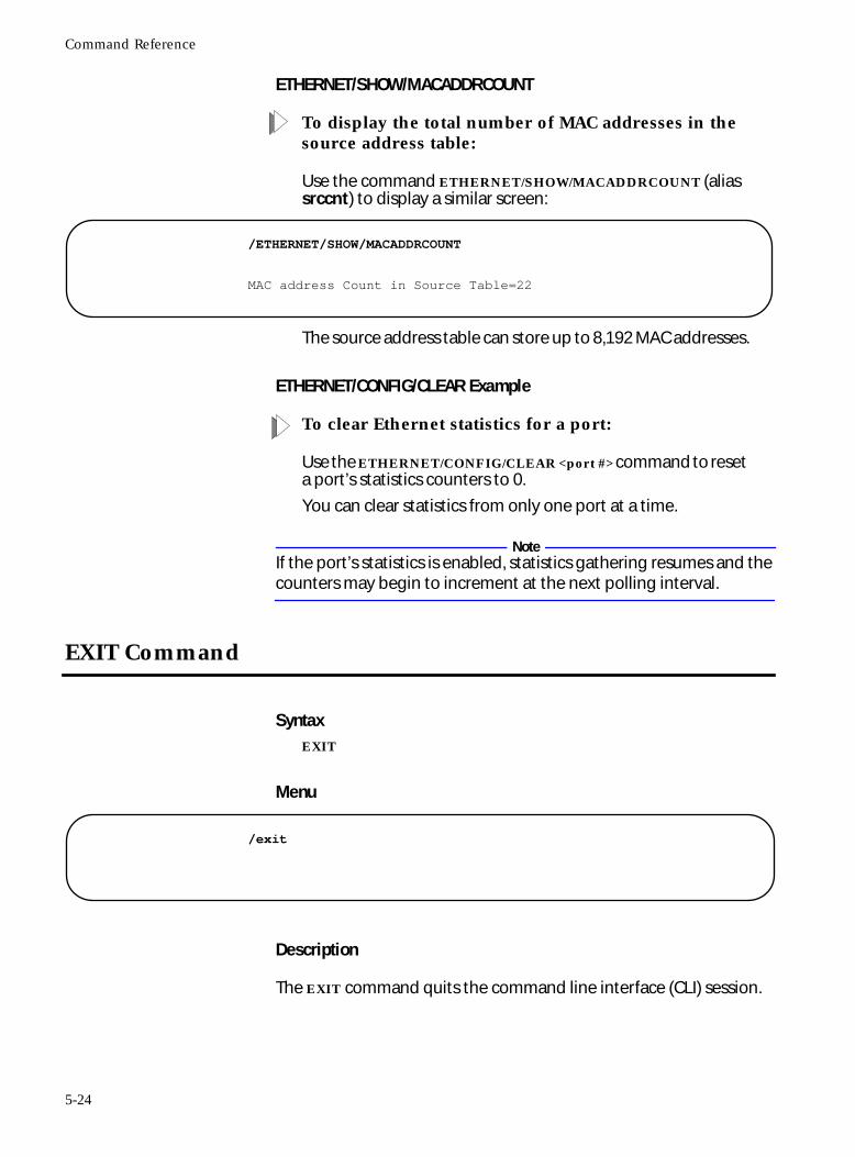
Command Reference
ETHERNET/SHOW/MACADDRCOUNT
To display the total number of MAC addresses in the source address table:
Use the command ETHERNET/SHOW/MACADDRCOUNT (alias srccnt) to display a similar screen:
The source address table can store up to 8,192 MAC addresses.
ETHERNET/CONFIG/CLEAR Example
To clear Ethernet statistics for a port:
Use the ETHERNET/CONFIG/CLEAR <port #> command to reset a port’s statistics counters to 0.
You can clear statistics from only one port at a time.
NoteIf the port’s statistics is enabled, statistics gathering resumes and the counters may begin to increment at the next polling interval.
EXIT Command
SyntaxEXIT
Menu
Description
The EXIT command quits the command line interface (CLI) session.
/ETHERNET/SHOW/MACADDRCOUNT
MAC address Count in Source Table=22
/exit
5-24
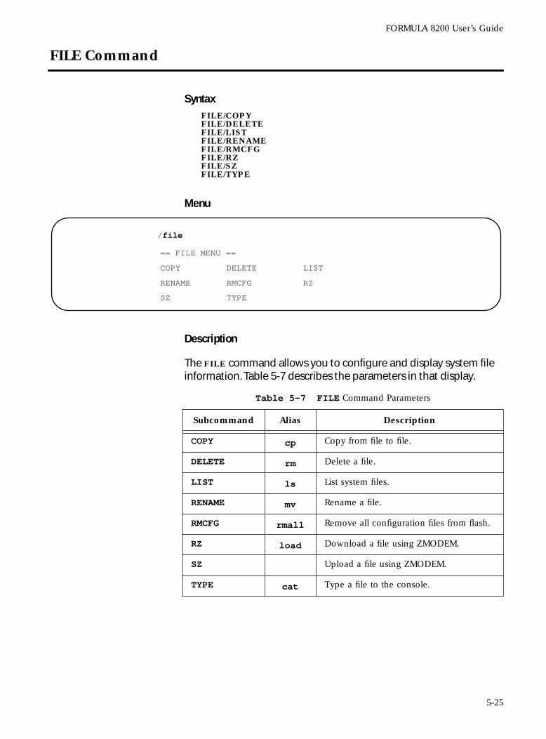
FORMULA 8200 User’s Guide
FILE Command
SyntaxFILE/COPYFILE/DELETEFILE/LISTFILE/RENAMEFILE/RMCFGFILE/RZFILE/SZFILE/TYPE
Menu
Description
The FILE command allows you to configure and display system file information. Table 5-7 describes the parameters in that display.
/file
== FILE MENU ==
COPY DELETE LIST
RENAME RMCFG RZ
SZ TYPE
Table 5-7 FILE Command Parameters
Subcommand Alias Description
COPY cp Copy from file to file.
DELETE rm Delete a file.
LIST ls List system files.
RENAME mv Rename a file.
RMCFG rmall Remove all configuration files from flash.
RZ load Download a file using ZMODEM.
SZ Upload a file using ZMODEM.
TYPE cat Type a file to the console.
5-25
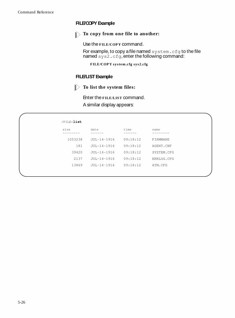
Command Reference
FILE/COPY Example
To copy from one file to another:
Use the FILE/COPY command.
For example, to copy a file named system.cfg to the file named sys2.cfg, enter the following command:
FILE/COPY system.cfg sys2.cfg
FILE/LIST Example
To list the system files:
Enter the FILE/LIST command.
A similar display appears:
/FILE>list
size--------
date------
time------
name--------
1053238 JUL-14-1916 09:18:12 FIRMWARE
181 JUL-14-1916 09:18:12 AGENT.CNF
39420 JUL-14-1916 09:18:12 SYSTEM.CFG
2137 JUL-14-1916 09:18:12 ERRLOG.CFG
13869 JUL-14-1916 09:18:12 ATM.CFG
5-26
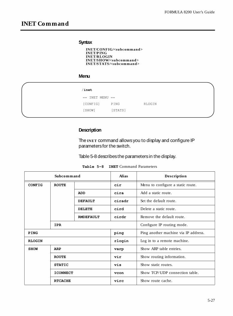
FORMULA 8200 User’s Guide
INET Command
SyntaxINET/CONFIG/<subcommand>INET/PINGINET/RLOGININET/SHOW/<subcommand>INET/STATS/<subcommand>
Menu
Description
The INET command allows you to display and configure IP parameters for the switch.
Table 5-8 describes the parameters in the display.
/inet
== INET MENU ==
[CONFIG] PING RLOGIN
[SHOW] [STATS]
Table 5-8 INET Command Parameters
Subcommand Alias Description
CONFIG ROUTE cir Menu to configure a static route.
ADD cira Add a static route.
DEFAULT ciradr Set the default route.
DELETE cird Delete a static route.
RMDEFAULT cirdr Remove the default route.
IPR Configure IP routing mode.
PING ping Ping another machine via IP address.
RLOGIN rlogin Log in to a remote machine.
SHOW ARP varp Show ARP table entries.
ROUTE vir Show routing information.
STATIC vis Show static routes.
ICONNECT vcon Show TCP/UDP connection table.
RTCACHE virc Show route cache.
5-27
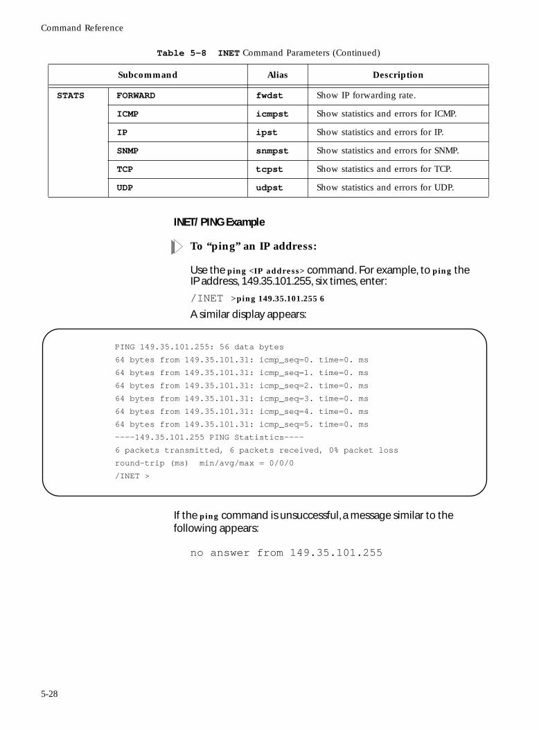
Command Reference
INET/ PING Example
To “ping” an IP address:
Use the ping <IP address> command. For example, to ping the IP address, 149.35.101.255, six times, enter:
/INET >ping 149.35.101.255 6
A similar display appears:
If the ping command is unsuccessful, a message similar to the following appears:
no answer from 149.35.101.255
STATS FORWARD fwdst Show IP forwarding rate.
ICMP icmpst Show statistics and errors for ICMP.
IP ipst Show statistics and errors for IP.
SNMP snmpst Show statistics and errors for SNMP.
TCP tcpst Show statistics and errors for TCP.
UDP udpst Show statistics and errors for UDP.
Table 5-8 INET Command Parameters (Continued)
Subcommand Alias Description
PING 149.35.101.255: 56 data bytes
64 bytes from 149.35.101.31: icmp_seq=0. time=0. ms
64 bytes from 149.35.101.31: icmp_seq=1. time=0. ms
64 bytes from 149.35.101.31: icmp_seq=2. time=0. ms
64 bytes from 149.35.101.31: icmp_seq=3. time=0. ms
64 bytes from 149.35.101.31: icmp_seq=4. time=0. ms
64 bytes from 149.35.101.31: icmp_seq=5. time=0. ms
----149.35.101.255 PING Statistics----
6 packets transmitted, 6 packets received, 0% packet loss
round-trip (ms) min/avg/max = 0/0/0
/INET >
5-28
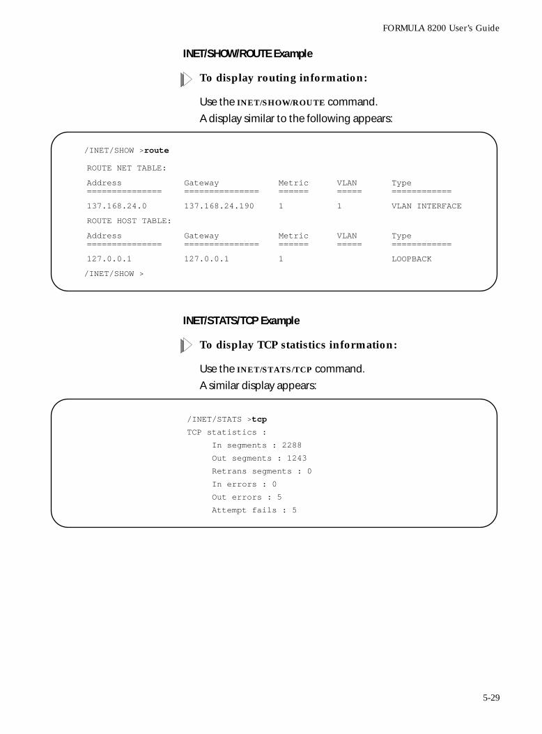
FORMULA 8200 User’s Guide
INET/SHOW/ROUTE Example
To display routing information:
Use the INET/SHOW/ROUTE command.
A display similar to the following appears:
INET/STATS/TCP Example
To display TCP statistics information:
Use the INET/STATS/TCP command.
A similar display appears:
/INET/SHOW >route
/INET/SHOW >
ROUTE NET TABLE:
Address===============
Gateway===============
Metric======
VLAN=====
Type============
137.168.24.0 137.168.24.190 1 1 VLAN INTERFACE
ROUTE HOST TABLE:
Address===============
Gateway===============
Metric======
VLAN=====
Type============
127.0.0.1 127.0.0.1 1 LOOPBACK
/INET/STATS >tcp
TCP statistics :
In segments : 2288
Out segments : 1243
Retrans segments : 0
In errors : 0
Out errors : 5
Attempt fails : 5
5-29
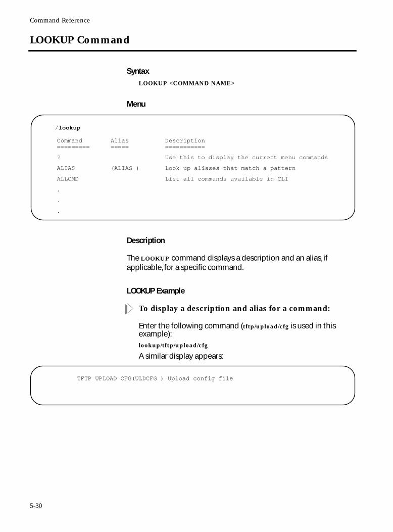
Command Reference
LOOKUP Command
SyntaxLOOKUP <COMMAND NAME>
Menu
Description
The LOOKUP command displays a description and an alias, if applicable, for a specific command.
LOOKUP Example
To display a description and alias for a command:
Enter the following command (tftp/upload/cfg is used in this example):lookup/tftp/upload/cfg
A similar display appears:
/lookup
Command=========
Alias=====
Description===========
? Use this to display the current menu commands
ALIAS (ALIAS ) Look up aliases that match a pattern
ALLCMD List all commands available in CLI
.
.
.
TFTP UPLOAD CFG(ULDCFG ) Upload config file
5-30
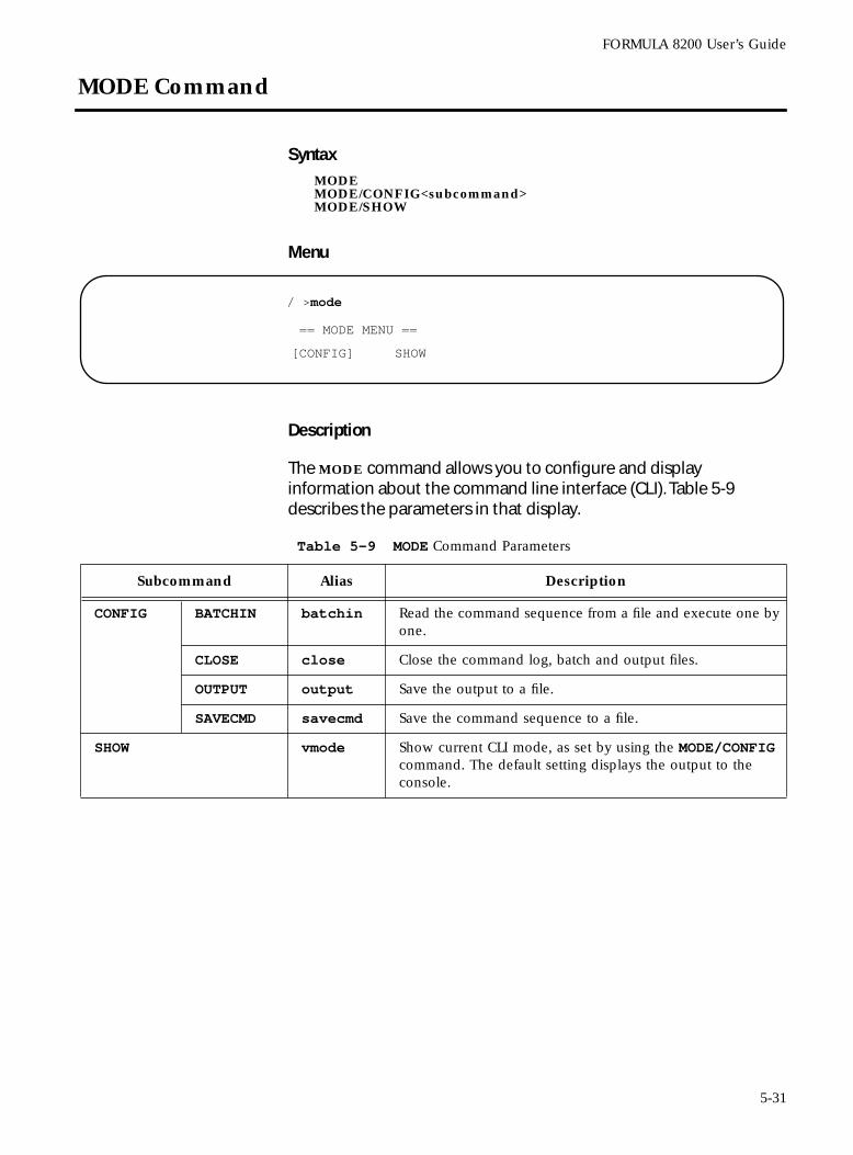
FORMULA 8200 User’s Guide
MODE Command
SyntaxMODEMODE/CONFIG<subcommand>MODE/SHOW
Menu
Description
The MODE command allows you to configure and display information about the command line interface (CLI). Table 5-9 describes the parameters in that display.
/ >mode
== MODE MENU ==
[CONFIG] SHOW
Table 5-9 MODE Command Parameters
Subcommand Alias Description
CONFIG BATCHIN batchin Read the command sequence from a file and execute one by one.
CLOSE close Close the command log, batch and output files.
OUTPUT output Save the output to a file.
SAVECMD savecmd Save the command sequence to a file.
SHOW vmode Show current CLI mode, as set by using the MODE/CONFIG command. The default setting displays the output to the console.
5-31
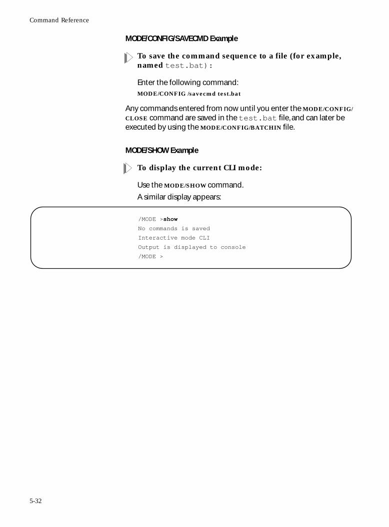
Command Reference
MODE/CONFIG/SAVECMD Example
To save the command sequence to a file (for example, named test.bat):
Enter the following command:MODE/CONFIG /savecmd test.bat
Any commands entered from now until you enter the MODE/CONFIG/
CLOSE command are saved in the test.bat file, and can later be executed by using the MODE/CONFIG/BATCHIN file.
MODE/SHOW Example
To display the current CLI mode:
Use the MODE/SHOW command.
A similar display appears:
/MODE >show
No commands is saved
Interactive mode CLI
Output is displayed to console
/MODE >
5-32
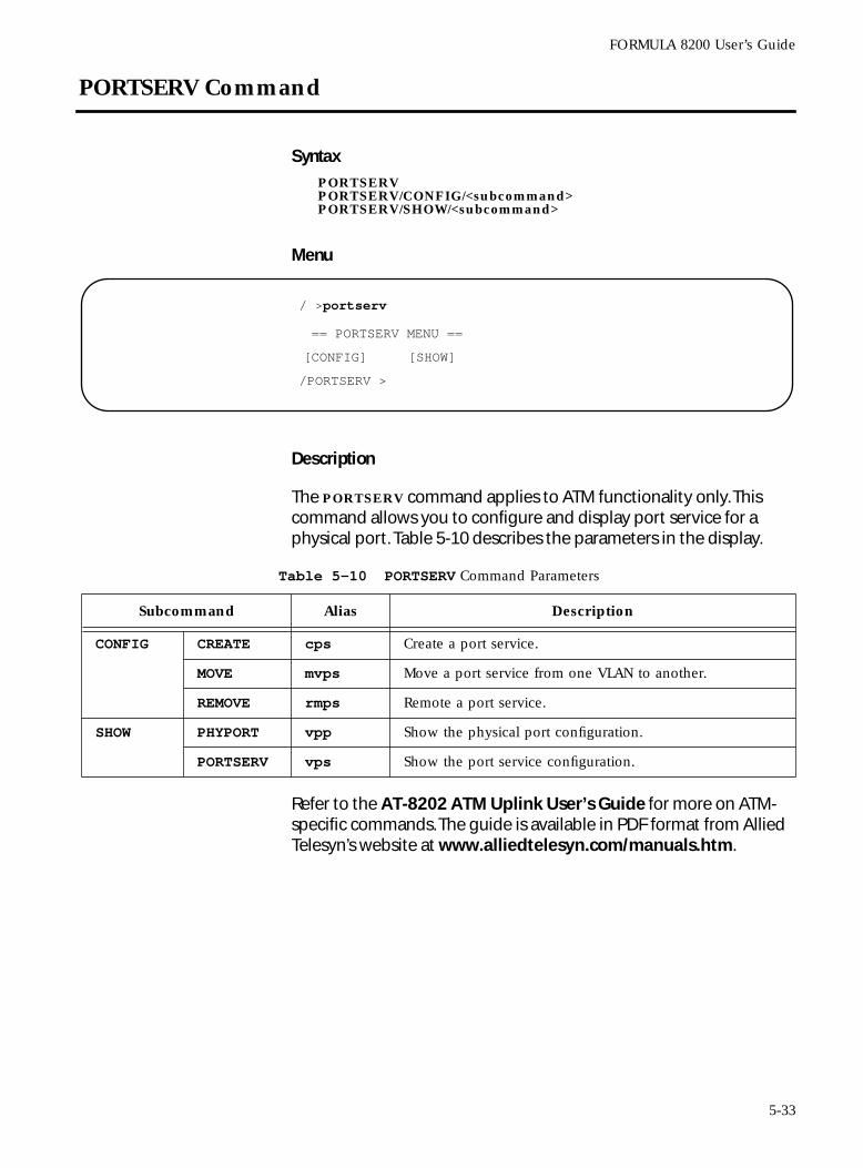
FORMULA 8200 User’s Guide
PORTSERV Command
SyntaxPORTSERVPORTSERV/CONFIG/<subcommand>PORTSERV/SHOW/<subcommand>
Menu
Description
The PORTSERV command applies to ATM functionality only. This command allows you to configure and display port service for a physical port. Table 5-10 describes the parameters in the display.
Refer to the AT-8202 ATM Uplink User’s Guide for more on ATM-specific commands. The guide is available in PDF format from Allied Telesyn’s website at www.alliedtelesyn.com/manuals.htm.
/ >portserv
/PORTSERV >
== PORTSERV MENU ==
[CONFIG] [SHOW]
Table 5-10 PORTSERV Command Parameters
Subcommand Alias Description
CONFIG CREATE cps Create a port service.
MOVE mvps Move a port service from one VLAN to another.
REMOVE rmps Remote a port service.
SHOW PHYPORT vpp Show the physical port configuration.
PORTSERV vps Show the port service configuration.
5-33
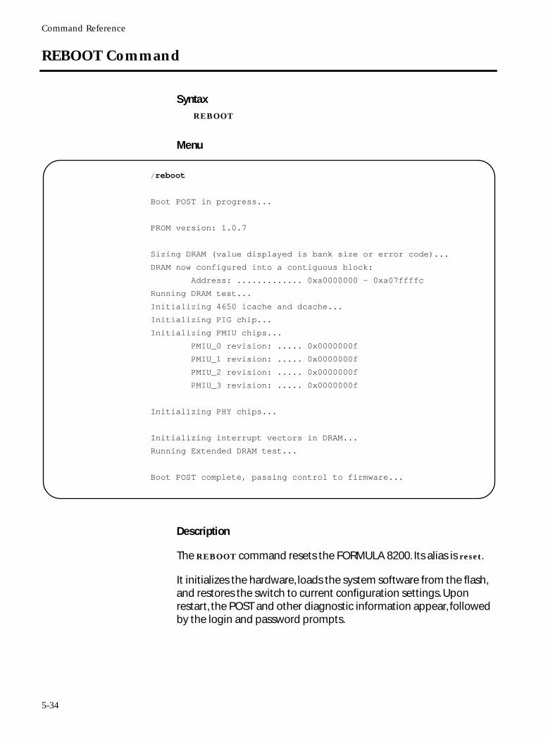
Command Reference
REBOOT Command
SyntaxREBOOT
Menu
Description
The REBOOT command resets the FORMULA 8200. Its alias is reset.
It initializes the hardware, loads the system software from the flash, and restores the switch to current configuration settings. Upon restart, the POST and other diagnostic information appear, followed by the login and password prompts.
/reboot
Boot POST in progress...
PROM version: 1.0.7
Sizing DRAM (value displayed is bank size or error code)...
DRAM now configured into a contiguous block:
Address: ............. 0xa0000000 - 0xa07ffffc
Running DRAM test...
Initializing 4650 icache and dcache...
Initializing PIG chip...
Initializing PMIU chips...
PMIU_0 revision: ..... 0x0000000f
PMIU_1 revision: ..... 0x0000000f
PMIU_2 revision: ..... 0x0000000f
PMIU_3 revision: ..... 0x0000000f
Initializing PHY chips...
Initializing interrupt vectors in DRAM...
Running Extended DRAM test...
Boot POST complete, passing control to firmware...
5-34
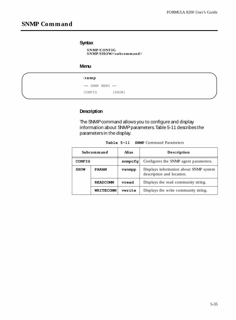
FORMULA 8200 User’s Guide
SNMP Command
SyntaxSNMP/CONFIGSNMP/SHOW/<subcommand>
Menu
Description
The SNMP command allows you to configure and display information about SNMP parameters. Table 5-11 describes the parameters in the display.
/snmp
== SNMP MENU ==
CONFIG [SHOW]
Table 5-11 SNMP Command Parameters
Subcommand Alias Description
CONFIG snmpcfg Configures the SNMP agent parameters.
SHOW PARAM vsnmpp Displays information about SNMP system description and location.
READCOMM vread Displays the read community string.
WRITECOMM vwrite Displays the write community string.
5-35
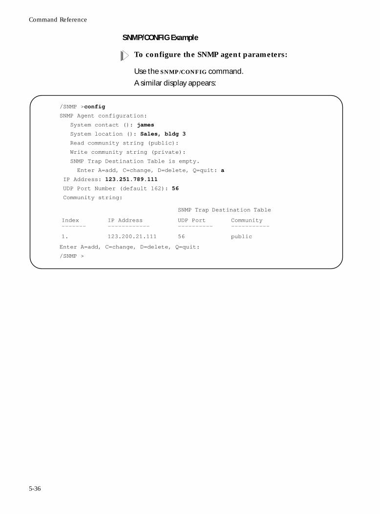
Command Reference
SNMP/CONFIG Example
To configure the SNMP agent parameters:
Use the SNMP/CONFIG command.
A similar display appears:
/SNMP >config
SNMP Agent configuration:
System contact (): james
System location (): Sales, bldg 3
Read community string (public):
Write community string (private):
SNMP Trap Destination Table is empty.
Enter A=add, C=change, D=delete, Q=quit: a
IP Address: 123.251.789.111
UDP Port Number (default 162): 56
Community string:
Enter A=add, C=change, D=delete, Q=quit:
/SNMP >
SNMP Trap Destination Table
Index-------
IP Address------------
UDP Port----------
Community-----------
1. 123.200.21.111 56 public
5-36
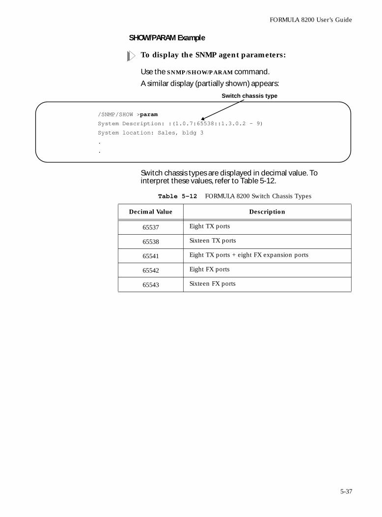
FORMULA 8200 User’s Guide
SHOW/PARAM Example
To display the SNMP agent parameters:
Use the SNMP/SHOW/PARAM command.
A similar display (partially shown) appears:
Switch chassis types are displayed in decimal value. To interpret these values, refer to Table 5-12.
/SNMP/SHOW >param
System Description: :(1.0.7:65538::1.3.0.2 - 9)
System location: Sales, bldg 3
.
.
Switch chassis type
Table 5-12 FORMULA 8200 Switch Chassis Types
Decimal Value Description
65537 Eight TX ports
65538 Sixteen TX ports
65541 Eight TX ports + eight FX expansion ports
65542 Eight FX ports
65543 Sixteen FX ports
5-37
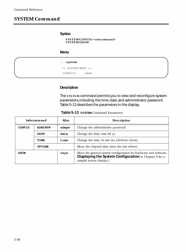
Command Reference
SYSTEM Command
SyntaxSYSTEM/CONFIG/<subcommand>SYSTEM/SHOW
Menu
Description
The SYSTEM command permits you to view and reconfigure system parameters, including the time, date, and administrator password. Table 5-13 describes the parameters in the display.
/ >system
== SYSTEM MENU ==
[CONFIG] SHOW
Table 5-13 SYSTEM Command Parameters
Subcommand Alias Description
CONFIG ADMINPW admpw Change the administrator password.
DATE date Change the date: mm dd yr.
TIME time Change the time: hr mn sec (24-hour clock).
UPTIME Show the elapsed time since the last reboot.
SHOW vsys Show the general system configuration for hardware and software. Displaying the System Configuration in Chapter 4 for a sample screen display.)
5-38
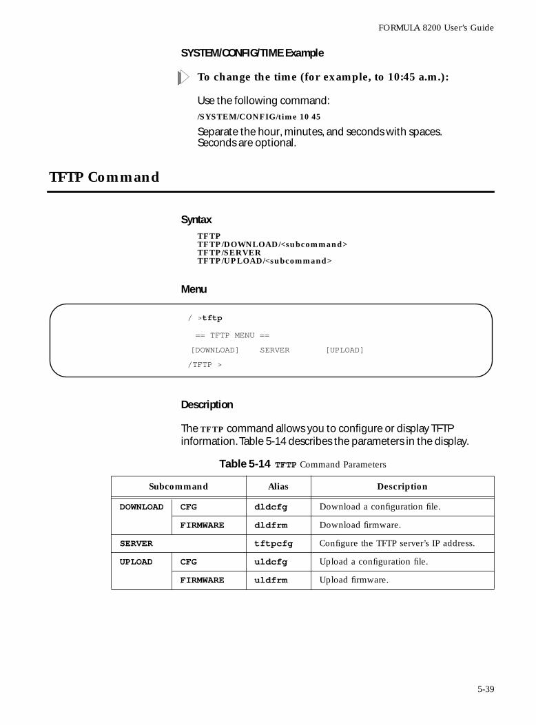
FORMULA 8200 User’s Guide
SYSTEM/CONFIG/TIME Example
To change the time (for example, to 10:45 a.m.):
Use the following command:
/SYSTEM/CONFIG/time 10 45
Separate the hour, minutes, and seconds with spaces. Seconds are optional.
TFTP Command
SyntaxTFTPTFTP/DOWNLOAD/<subcommand>TFTP/SERVERTFTP/UPLOAD/<subcommand>
Menu
Description
The TFTP command allows you to configure or display TFTP information. Table 5-14 describes the parameters in the display.
/ >tftp
/TFTP >
== TFTP MENU ==
[DOWNLOAD] SERVER [UPLOAD]
Table 5-14 TFTP Command Parameters
Subcommand Alias Description
DOWNLOAD CFG dldcfg Download a configuration file.
FIRMWARE dldfrm Download firmware.
SERVER tftpcfg Configure the TFTP server’s IP address.
UPLOAD CFG uldcfg Upload a configuration file.
FIRMWARE uldfrm Upload firmware.
5-39
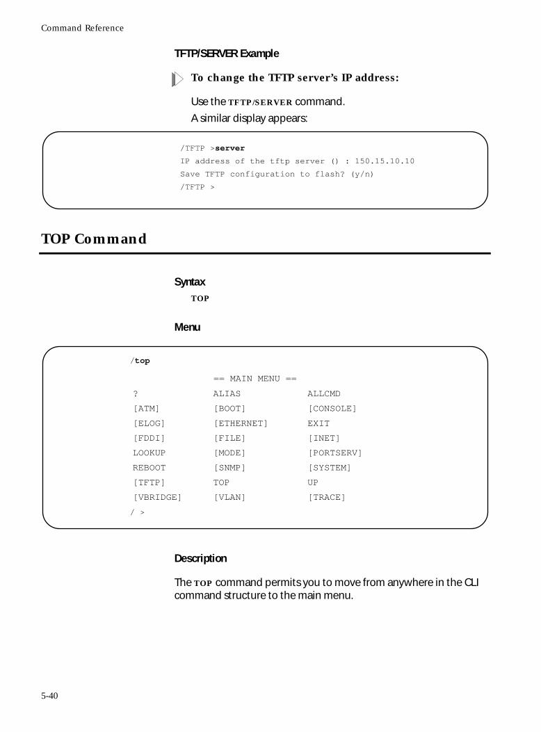
Command Reference
TFTP/SERVER Example
To change the TFTP server’s IP address:
Use the TFTP/SERVER command.
A similar display appears:
TOP Command
SyntaxTOP
Menu
Description
The TOP command permits you to move from anywhere in the CLI command structure to the main menu.
/TFTP >server
IP address of the tftp server () : 150.15.10.10
Save TFTP configuration to flash? (y/n)
/TFTP >
/top
/ >
== MAIN MENU ==
? ALIAS ALLCMD
[ATM] [BOOT] [CONSOLE]
[ELOG] [ETHERNET] EXIT
[FDDI] [FILE] [INET]
LOOKUP [MODE] [PORTSERV]
REBOOT [SNMP] [SYSTEM]
[TFTP] TOP UP
[VBRIDGE] [VLAN] [TRACE]
5-40
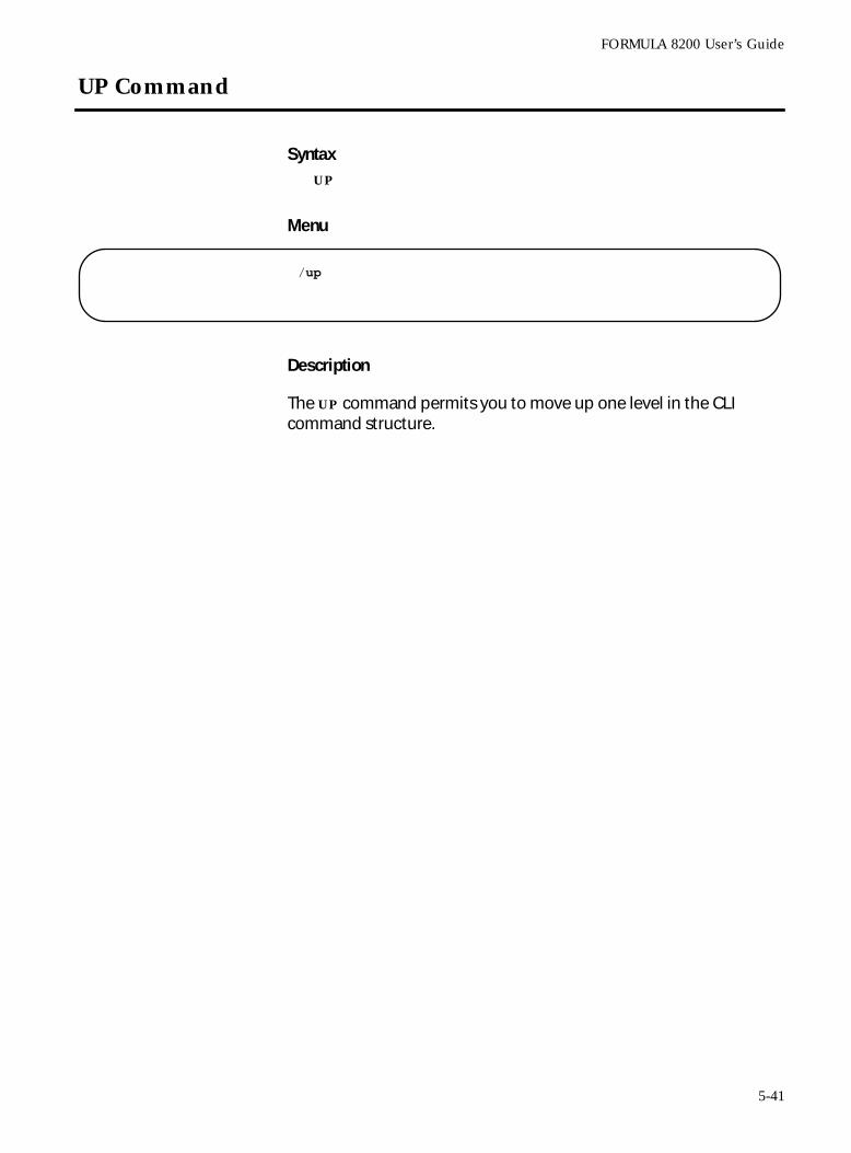
FORMULA 8200 User’s Guide
UP Command
SyntaxUP
Menu
Description
The UP command permits you to move up one level in the CLI command structure.
/up
5-41
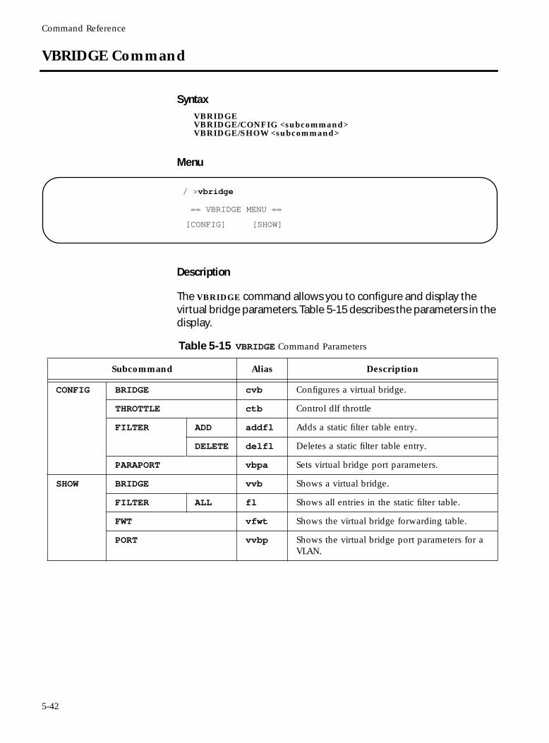
Command Reference
VBRIDGE Command
SyntaxVBRIDGEVBRIDGE/CONFIG <subcommand>VBRIDGE/SHOW <subcommand>
Menu
Description
The VBRIDGE command allows you to configure and display the virtual bridge parameters. Table 5-15 describes the parameters in the display.
/ >vbridge
== VBRIDGE MENU ==
[CONFIG] [SHOW]
Table 5-15 VBRIDGE Command Parameters
Subcommand Alias Description
CONFIG BRIDGE cvb Configures a virtual bridge.
THROTTLE ctb Control dlf throttle
FILTER ADD addfl Adds a static filter table entry.
DELETE delfl Deletes a static filter table entry.
PARAPORT vbpa Sets virtual bridge port parameters.
SHOW BRIDGE vvb Shows a virtual bridge.
FILTER ALL fl Shows all entries in the static filter table.
FWT vfwt Shows the virtual bridge forwarding table.
PORT vvbp Shows the virtual bridge port parameters for a VLAN.
5-42
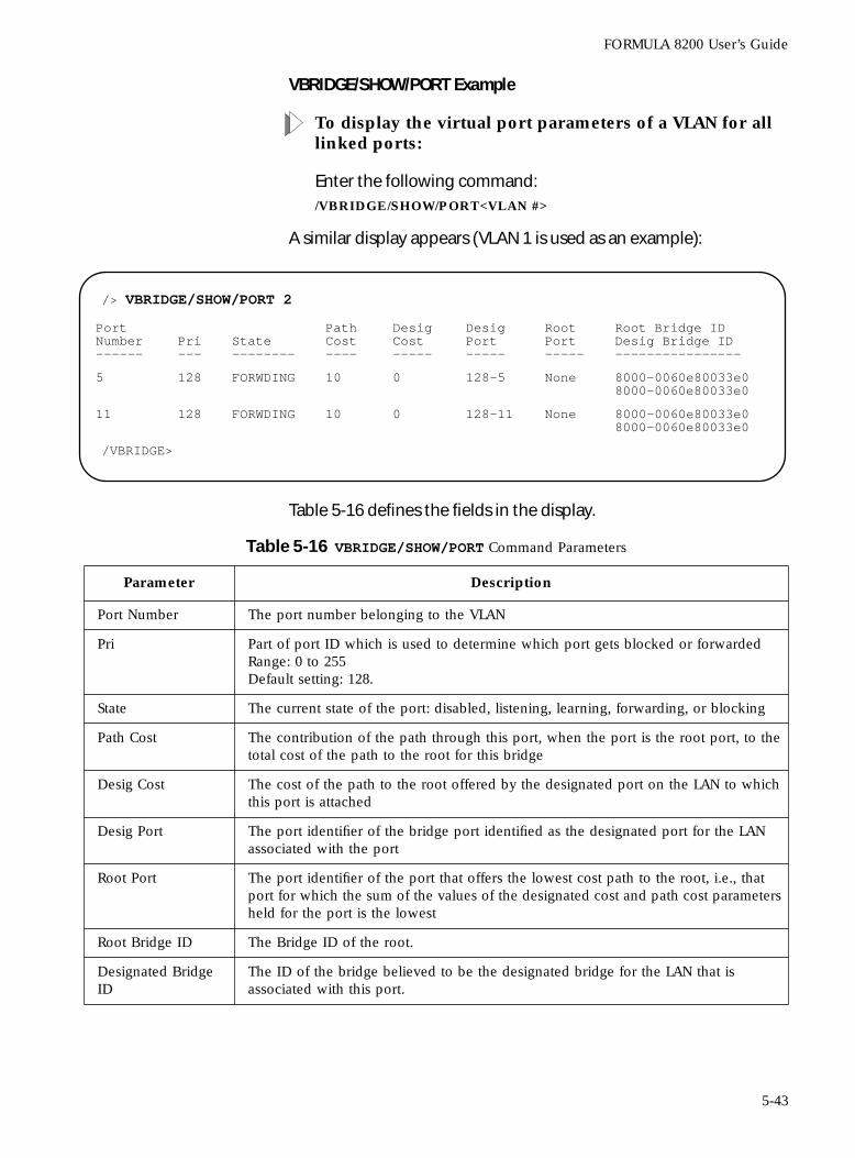
FORMULA 8200 User’s Guide
VBRIDGE/SHOW/PORT Example
To display the virtual port parameters of a VLAN for all linked ports:
Enter the following command: /VBRIDGE/SHOW/PORT<VLAN #>
A similar display appears (VLAN 1 is used as an example):
Table 5-16 defines the fields in the display.
/> VBRIDGE/SHOW/PORT 2
/VBRIDGE>
PortNumber------
Pri---
State--------
PathCost----
DesigCost-----
DesigPort-----
RootPort-----
Root Bridge IDDesig Bridge ID----------------
5 128 FORWDING 10 0 128-5 None 8000-0060e80033e08000-0060e80033e0
11 128 FORWDING 10 0 128-11 None 8000-0060e80033e08000-0060e80033e0
Table 5-16 VBRIDGE/SHOW/PORT Command Parameters
Parameter Description
Port Number The port number belonging to the VLAN
Pri Part of port ID which is used to determine which port gets blocked or forwardedRange: 0 to 255Default setting: 128.
State The current state of the port: disabled, listening, learning, forwarding, or blocking
Path Cost The contribution of the path through this port, when the port is the root port, to the total cost of the path to the root for this bridge
Desig Cost The cost of the path to the root offered by the designated port on the LAN to which this port is attached
Desig Port The port identifier of the bridge port identified as the designated port for the LAN associated with the port
Root Port The port identifier of the port that offers the lowest cost path to the root, i.e., that port for which the sum of the values of the designated cost and path cost parameters held for the port is the lowest
Root Bridge ID The Bridge ID of the root.
Designated Bridge ID
The ID of the bridge believed to be the designated bridge for the LAN that is associated with this port.
5-43
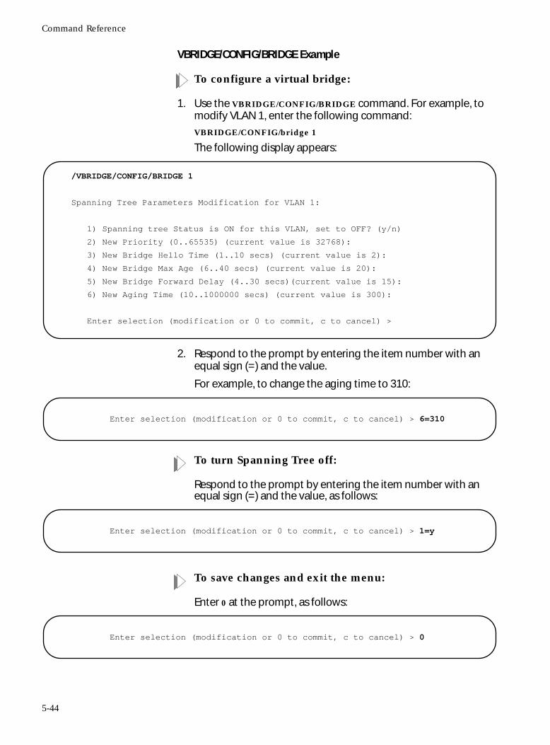
Command Reference
VBRIDGE/CONFIG/BRIDGE Example
To configure a virtual bridge:
1. Use the VBRIDGE/CONFIG/BRIDGE command. For example, to modify VLAN 1, enter the following command:
VBRIDGE/CONFIG/bridge 1
The following display appears:
2. Respond to the prompt by entering the item number with an equal sign (=) and the value.
For example, to change the aging time to 310:
To turn Spanning Tree off:
Respond to the prompt by entering the item number with an equal sign (=) and the value, as follows:
To save changes and exit the menu:
Enter 0 at the prompt, as follows:
/VBRIDGE/CONFIG/BRIDGE 1
Spanning Tree Parameters Modification for VLAN 1:
1) Spanning tree Status is ON for this VLAN, set to OFF? (y/n)
2) New Priority (0..65535) (current value is 32768):
3) New Bridge Hello Time (1..10 secs) (current value is 2):
4) New Bridge Max Age (6..40 secs) (current value is 20):
5) New Bridge Forward Delay (4..30 secs)(current value is 15):
6) New Aging Time (10..1000000 secs) (current value is 300):
Enter selection (modification or 0 to commit, c to cancel) >
Enter selection (modification or 0 to commit, c to cancel) > 6=310
Enter selection (modification or 0 to commit, c to cancel) > 1=y
Enter selection (modification or 0 to commit, c to cancel) > 0
5-44
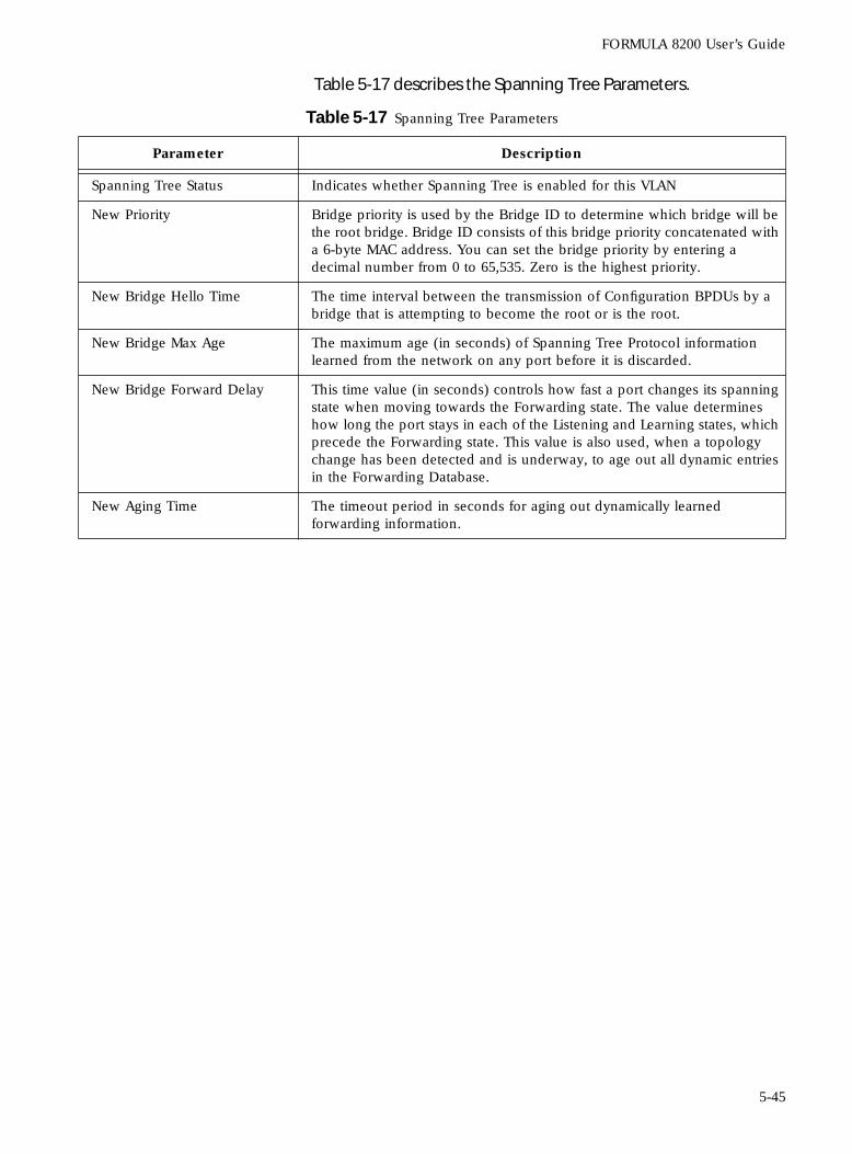
FORMULA 8200 User’s Guide
Table 5-17 describes the Spanning Tree Parameters.
Table 5-17 Spanning Tree Parameters
Parameter Description
Spanning Tree Status Indicates whether Spanning Tree is enabled for this VLAN
New Priority Bridge priority is used by the Bridge ID to determine which bridge will be the root bridge. Bridge ID consists of this bridge priority concatenated with a 6-byte MAC address. You can set the bridge priority by entering a decimal number from 0 to 65,535. Zero is the highest priority.
New Bridge Hello Time The time interval between the transmission of Configuration BPDUs by a bridge that is attempting to become the root or is the root.
New Bridge Max Age The maximum age (in seconds) of Spanning Tree Protocol information learned from the network on any port before it is discarded.
New Bridge Forward Delay This time value (in seconds) controls how fast a port changes its spanning state when moving towards the Forwarding state. The value determines how long the port stays in each of the Listening and Learning states, which precede the Forwarding state. This value is also used, when a topology change has been detected and is underway, to age out all dynamic entries in the Forwarding Database.
New Aging Time The timeout period in seconds for aging out dynamically learned forwarding information.
5-45
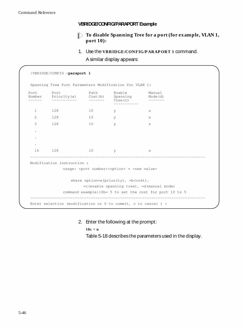
Command Reference
VBRIDGE/CONFIG/PARAPORT Example
To disable Spanning Tree for a port (for example, VLAN 1, port 10):
1. Use the VBRIDGE/CONFIG/PARAPORT 1 command.
A similar display appears:
2. Enter the following at the prompt:
10c = n
Table 5-18 describes the parameters used in the display.
/VBRIDGE/CONFIG >paraport 1
Spanning Tree Port Parameters Modification for VLAN 1:
------------------------------------------------------------------------------
Modification instruction :
usage: <port number><option> = <new value>
where option=a(priority), =b(cost),
=c(enable spanning tree), =d(manual mode)
command example:10b= 5 to set the cost for port 10 to 5
------------------------------------------------------------------------------
Enter selection (modification or 0 to commit, c to cancel ) >
PortNumber------
PortPriority(a)-----------
PathCost(b)-------
EnableSpanning Tree(c)-----------
ManualMode(d)-------
1 128 10 y s
2 128 10 y s
3 128 10 y s
.
.
.
16 128 10 y s
5-46
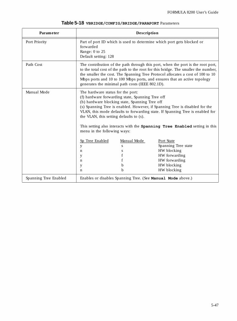
FORMULA 8200 User’s Guide
Table 5-18 VBRIDGE/CONFIG/BRIDGE/PARAPORT Parameters
Parameter Description
Port Priority Part of port ID which is used to determine which port gets blocked or forwardedRange: 0 to 25Default setting: 128
Path Cost The contribution of the path through this port, when the port is the root port, to the total cost of the path to the root for this bridge. The smaller the number, the smaller the cost. The Spanning Tree Protocol allocates a cost of 100 to 10 Mbps ports and 10 to 100 Mbps ports, and ensures that an active topology generates the minimal path costs (IEEE 802.1D).
Manual Mode The hardware status for the port:(f) hardware forwarding state, Spanning Tree off(b) hardware blocking state, Spanning Tree off(s) Spanning Tree is enabled. However, if Spanning Tree is disabled for the VLAN, this mode defaults to forwarding state. If Spanning Tree is enabled for the VLAN, this setting defaults to (s).
This setting also interacts with the Spanning Tree Enabled setting in this menu in the following ways:
Sp Tree Enabled Manual Mode Port State y s Spanning Tree staten s HW blockingy f HW forwardingn f HW forwardingy b HW blockingn b HW blocking
Spanning Tree Enabled Enables or disables Spanning Tree. (See Manual Mode above.)
5-47
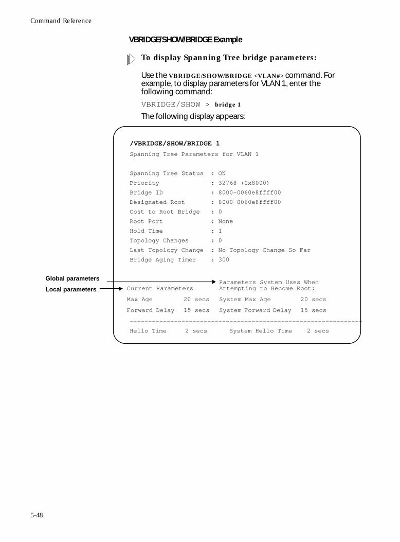
Command Reference
VBRIDGE/SHOW/BRIDGE Example
To display Spanning Tree bridge parameters:
Use the VBRIDGE/SHOW/BRIDGE <VLAN#> command. For example, to display parameters for VLAN 1, enter the following command:
VBRIDGE/SHOW > bridge 1
The following display appears:
/VBRIDGE/SHOW/BRIDGE 1
Spanning Tree Parameters for VLAN 1
Spanning Tree Status : ON
Priority : 32768 (0x8000)
Bridge ID : 8000-0060e8ffff00
Designated Root : 8000-0060e8ffff00
Cost to Root Bridge : 0
Root Port : None
Hold Time : 1
Topology Changes : 0
Last Topology Change : No Topology Change So Far
Bridge Aging Timer : 300
----------------------------------------------------------------
Hello Time 2 secs System Hello Time 2 secs
Current ParametersParameters System Uses WhenAttempting to Become Root:
Max Age 20 secs System Max Age 20 secs
Forward Delay 15 secs System Forward Delay 15 secs
Global parameters
Local parameters
5-48
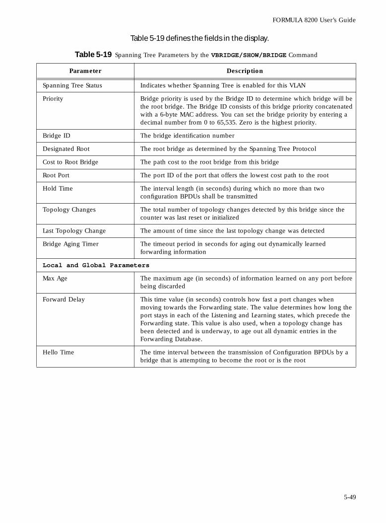
FORMULA 8200 User’s Guide
Table 5-19 defines the fields in the display.
Table 5-19 Spanning Tree Parameters by the VBRIDGE/SHOW/BRIDGE Command
Parameter Description
Spanning Tree Status Indicates whether Spanning Tree is enabled for this VLAN
Priority Bridge priority is used by the Bridge ID to determine which bridge will be the root bridge. The Bridge ID consists of this bridge priority concatenated with a 6-byte MAC address. You can set the bridge priority by entering a decimal number from 0 to 65,535. Zero is the highest priority.
Bridge ID The bridge identification number
Designated Root The root bridge as determined by the Spanning Tree Protocol
Cost to Root Bridge The path cost to the root bridge from this bridge
Root Port The port ID of the port that offers the lowest cost path to the root
Hold Time The interval length (in seconds) during which no more than two configuration BPDUs shall be transmitted
Topology Changes The total number of topology changes detected by this bridge since the counter was last reset or initialized
Last Topology Change The amount of time since the last topology change was detected
Bridge Aging Timer The timeout period in seconds for aging out dynamically learned forwarding information
Local and Global Parameters
Max Age The maximum age (in seconds) of information learned on any port before being discarded
Forward Delay This time value (in seconds) controls how fast a port changes when moving towards the Forwarding state. The value determines how long the port stays in each of the Listening and Learning states, which precede the Forwarding state. This value is also used, when a topology change has been detected and is underway, to age out all dynamic entries in the Forwarding Database.
Hello Time The time interval between the transmission of Configuration BPDUs by a bridge that is attempting to become the root or is the root
5-49
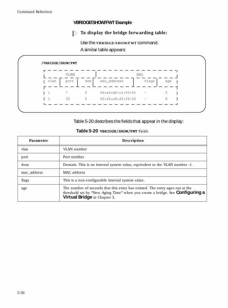
Command Reference
VBRIDGE/SHOW/FWT Example
To display the bridge forwarding table:
Use the VBRIDGE/SHOW/FWT command.
A similar table appears:
Table 5-20 describes the fields that appear in the display:
/VBRIDGE/SHOW/FWT
VLAN ARL
vlan port dom mac_address flags age
1 7 0 00:a0:d2:c1:55:01 — 5
1 33 0 00:60:e8:ff:ff:50 — 0
Table 5-20 VBRIDGE/SHOW/FWT Fields
Parameter Description
vlan VLAN number
port Port number
dom Domain. This is an internal system value, equivalent to the VLAN number -1.
mac_address MAC address
flags This is a non-configurable internal system value.
age The number of seconds that this entry has existed. The entry ages out at the threshold set by “New Aging Time” when you create a bridge. See Configuring a Virtual Bridge in Chapter 3.
5-50
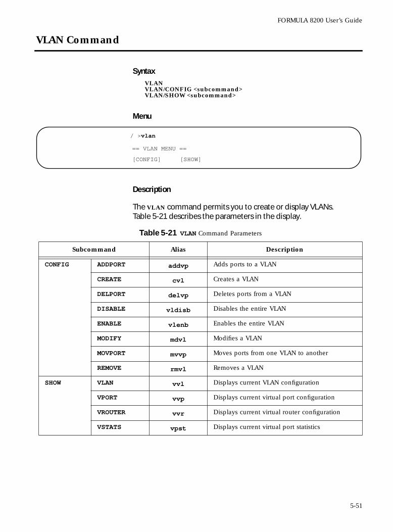
FORMULA 8200 User’s Guide
VLAN Command
SyntaxVLANVLAN/CONFIG <subcommand>VLAN/SHOW <subcommand>
Menu
Description
The VLAN command permits you to create or display VLANs. Table 5-21 describes the parameters in the display.
/ >vlan
== VLAN MENU ==
[CONFIG] [SHOW]
Table 5-21 VLAN Command Parameters
Subcommand Alias Description
CONFIG ADDPORT addvp Adds ports to a VLAN
CREATE cvl Creates a VLAN
DELPORT delvp Deletes ports from a VLAN
DISABLE vldisb Disables the entire VLAN
ENABLE vlenb Enables the entire VLAN
MODIFY mdvl Modifies a VLAN
MOVPORT mvvp Moves ports from one VLAN to another
REMOVE rmvl Removes a VLAN
SHOW VLAN vvl Displays current VLAN configuration
VPORT vvp Displays current virtual port configuration
VROUTER vvr Displays current virtual router configuration
VSTATS vpst Displays current virtual port statistics
5-51
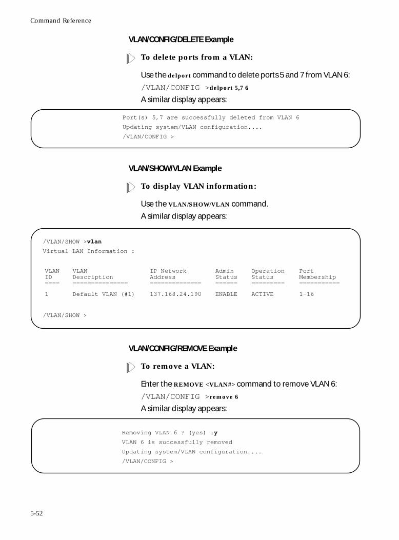
Command Reference
VLAN/CONFIG/DELETE Example
To delete ports from a VLAN:
Use the delport command to delete ports 5 and 7 from VLAN 6:
/VLAN/CONFIG >delport 5,7 6
A similar display appears:
VLAN/SHOW/VLAN Example
To display VLAN information:
Use the VLAN/SHOW/VLAN command.
A similar display appears:
VLAN/CONFIG/REMOVE Example
To remove a VLAN:
Enter the REMOVE <VLAN#> command to remove VLAN 6:
/VLAN/CONFIG >remove 6
A similar display appears:
Port(s) 5,7 are successfully deleted from VLAN 6
Updating system/VLAN configuration....
/VLAN/CONFIG >
/VLAN/SHOW >vlan
Virtual LAN Information :
/VLAN/SHOW >
VLANID====
VLANDescription===============
IP NetworkAddress==============
AdminStatus======
OperationStatus=========
PortMembership===========
1 Default VLAN (#1) 137.168.24.190 ENABLE ACTIVE 1-16
Removing VLAN 6 ? (yes) :y
VLAN 6 is successfully removed
Updating system/VLAN configuration....
/VLAN/CONFIG >
5-52
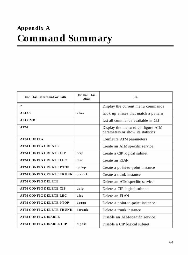
Appendix A
Command Summary
Use This Command or PathOr Use This
AliasTo
? Display the current menu commands
ALIAS alias Look up aliases that match a pattern
ALLCMD List all commands available in CLI
ATM Display the menu to configure ATM parameters or show its statistics
ATM CONFIG Configure ATM parameters
ATM CONFIG CREATE Create an ATM specific service
ATM CONFIG CREATE CIP ccip Create a CIP logical subnet
ATM CONFIG CREATE LEC clec Create an ELAN
ATM CONFIG CREATE PTOP cptop Create a point-to-point instance
ATM CONFIG CREATE TRUNK ctrunk Create a trunk instance
ATM CONFIG DELETE Delete an ATM-specific service
ATM CONFIG DELETE CIP dcip Delete a CIP logical subnet
ATM CONFIG DELETE LEC dlec Delete an ELAN
ATM CONFIG DELETE PTOP dptop Delete a point-to-point instance
ATM CONFIG DELETE TRUNK dtrunk Delete a trunk instance
ATM CONFIG DISABLE Disable an ATM-specific service
ATM CONFIG DISABLE CIP cipdis Disable a CIP logical subnet
A-1
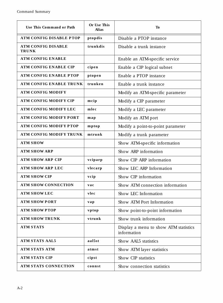
Command Summary
ATM CONFIG DISABLE PTOP ptopdis Disable a PTOP instance
ATM CONFIG DISABLE TRUNK
trunkdis Disable a trunk instance
ATM CONFIG ENABLE Enable an ATM-specific service
ATM CONFIG ENABLE CIP cipen Enable a CIP logical subnet
ATM CONFIG ENABLE PTOP ptopen Enable a PTOP instance
ATM CONFIG ENABLE TRUNK trunken Enable a trunk instance
ATM CONFIG MODIFY Modify an ATM-specific parameter
ATM CONFIG MODIFY CIP mcip Modify a CIP parameter
ATM CONFIG MODIFY LEC mlec Modify a LEC parameter
ATM CONFIG MODIFY PORT map Modify an ATM port
ATM CONFIG MODIFY PTOP mptop Modify a point-to-point parameter
ATM CONFIG MODIFY TRUNK mtrunk Modify a trunk parameter
ATM SHOW Show ATM-specific information
ATM SHOW ARP Show ARP information
ATM SHOW ARP CIP vciparp Show CIP ARP information
ATM SHOW ARP LEC vlecarp Show LEC ARP Information
ATM SHOW CIP vcip Show CIP information
ATM SHOW CONNECTION vac Show ATM connection information
ATM SHOW LEC vlec Show LEC Information
ATM SHOW PORT vap Show ATM Port Information
ATM SHOW PTOP vptop Show point-to-point information
ATM SHOW TRUNK vtrunk Show trunk information
ATM STATS Display a menu to show ATM statistics information
ATM STATS AAL5 aal5st Show AAL5 statistics
ATM STATS ATM atmst Show ATM layer statistics
ATM STATS CIP cipst Show CIP statistics
ATM STATS CONNECTION connst Show connection statistics
Use This Command or PathOr Use This
AliasTo
A-2
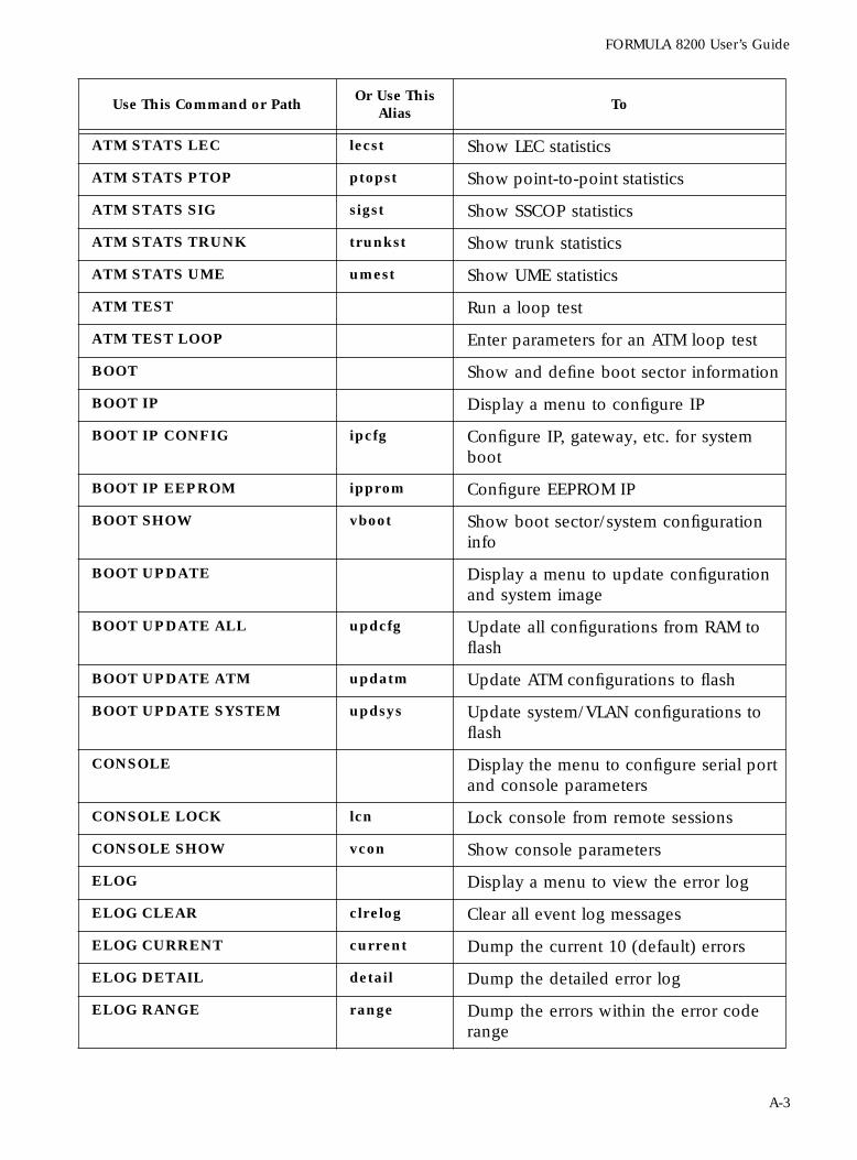
FORMULA 8200 User’s Guide
ATM STATS LEC lecst Show LEC statistics
ATM STATS PTOP ptopst Show point-to-point statistics
ATM STATS SIG sigst Show SSCOP statistics
ATM STATS TRUNK trunkst Show trunk statistics
ATM STATS UME umest Show UME statistics
ATM TEST Run a loop test
ATM TEST LOOP Enter parameters for an ATM loop test
BOOT Show and define boot sector information
BOOT IP Display a menu to configure IP
BOOT IP CONFIG ipcfg Configure IP, gateway, etc. for system boot
BOOT IP EEPROM ipprom Configure EEPROM IP
BOOT SHOW vboot Show boot sector/system configuration info
BOOT UPDATE Display a menu to update configuration and system image
BOOT UPDATE ALL updcfg Update all configurations from RAM to flash
BOOT UPDATE ATM updatm Update ATM configurations to flash
BOOT UPDATE SYSTEM updsys Update system/VLAN configurations to flash
CONSOLE Display the menu to configure serial port and console parameters
CONSOLE LOCK lcn Lock console from remote sessions
CONSOLE SHOW vcon Show console parameters
ELOG Display a menu to view the error log
ELOG CLEAR clrelog Clear all event log messages
ELOG CURRENT current Dump the current 10 (default) errors
ELOG DETAIL detail Dump the detailed error log
ELOG RANGE range Dump the errors within the error code range
Use This Command or PathOr Use This
AliasTo
A-3
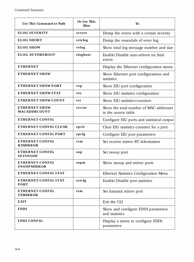
Command Summary
ELOG SEVERITY severe Dump the errors with a certain severity
ELOG SHORT srtelog Dump the essentials of error log
ELOG SHOW velog Show total log message number and size
ELOG AUTOREBOOT elogboot Enable/Disable auto-reboot on fatal errors
ETHERNET Display the Ethernet configuration menu
ETHERNET SHOW Show Ethernet port configurations and statistics
ETHERNET SHOW PORT vep Show EIU port configuration
ETHERNET SHOW STAT ves Show EIU statistics configuration
ETHERNET SHOW COUNT est Show EIU statistics/counters
ETHERNET SHOW MACADDRCOUNT
srccnt Show the total number of MAC addresses in the source table
ETHERNET CONFIG Configure EIU ports and statistical output
ETHERNET CONFIG CLEAR epclr Clear EIU statistics counters for a port
ETHERNET CONFIG PORT epcfg Configure EIU port parameters
ETHERNET CONFIG RXMIRROR
rxm Set receive mirror RT information
ETHERNET CONFIG SETSNOOP
snp Set snoop port
ETHERNET CONFIG SNOOPMIRROR
snpm Show snoop and mirror ports
ETHERNET CONFIG STAT Ethernet Statistics Configuration Menu
ETHERNET CONFIG STAT PORT
estcfg Enable/Disable port statistics
ETHERNET CONFIG TXMIRROR
txm Set transmit mirror port
EXIT Exit the CLI
FDDI Show and configure FDDI parameters and statistics
FDDI CONFIG Display a menu to configure FDDI parameters
Use This Command or PathOr Use This
AliasTo
A-4
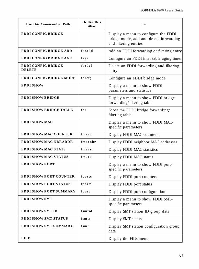
FORMULA 8200 User’s Guide
FDDI CONFIG BRIDGE Display a menu to configure the FDDI bridge mode, add and delete forwarding and filtering entries
FDDI CONFIG BRIDGE ADD fbradd Add an FDDI forwarding or filtering entry
FDDI CONFIG BRIDGE AGE fage Configure an FDDI filter table aging timer
FDDI CONFIG BRIDGE DELETE
fbrdel Delete an FDDI forwarding and filtering entry
FDDI CONFIG BRIDGE MODE fbrcfg Configure an FDDI bridge mode
FDDI SHOW Display a menu to show FDDI parameters and statistics
FDDI SHOW BRIDGE Display a menu to show FDDI bridge forwarding/filtering table
FDDI SHOW BRIDGE TABLE fbr Show the FDDI bridge forwarding/filtering table
FDDI SHOW MAC Display a menu to show FDDI MAC-specific parameters
FDDI SHOW MAC COUNTER fmacc Display FDDI MAC counters
FDDI SHOW MAC NBRADDR fmacnbr Display FDDI neighbor MAC addresses
FDDI SHOW MAC STATS fmacst Display FDDI MAC statistics
FDDI SHOW MAC STATUS fmacs Display FDDI MAC status
FDDI SHOW PORT Display a menu to show FDDI port-specific parameters
FDDI SHOW PORT COUNTER fportc Display FDDI port counters
FDDI SHOW PORT STATUS fports Display FDDI port status
FDDI SHOW PORT SUMMARY fport Display FDDI port configuration
FDDI SHOW SMT Display a menu to show FDDI SMT-specific parameters
FDDI SHOW SMT ID fsmtid Display SMT station ID group data
FDDI SHOW SMT STATUS fsmts Display SMT status
FDDI SHOW SMT SUMMARY fsmt Display SMT station configuration group data
FILE Display the FILE menu
Use This Command or PathOr Use This
AliasTo
A-5
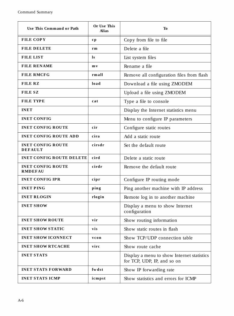
Command Summary
FILE COPY cp Copy from file to file
FILE DELETE rm Delete a file
FILE LIST ls List system files
FILE RENAME mv Rename a file
FILE RMCFG rmall Remove all configuration files from flash
FILE RZ load Download a file using ZMODEM
FILE SZ Upload a file using ZMODEM
FILE TYPE cat Type a file to console
INET Display the Internet statistics menu
INET CONFIG Menu to configure IP parameters
INET CONFIG ROUTE cir Configure static routes
INET CONFIG ROUTE ADD cira Add a static route
INET CONFIG ROUTE DEFAULT
cirsdr Set the default route
INET CONFIG ROUTE DELETE cird Delete a static route
INET CONFIG ROUTE RMDEFAU
cirdr Remove the default route
INET CONFIG IPR cipr Configure IP routing mode
INET PING ping Ping another machine with IP address
INET RLOGIN rlogin Remote log in to another machine
INET SHOW Display a menu to show Internet configuration
INET SHOW ROUTE vir Show routing information
INET SHOW STATIC vis Show static routes in flash
INET SHOW ICONNECT vcon Show TCP/UDP connection table
INET SHOW RTCACHE virc Show route cache
INET STATS Display a menu to show Internet statistics for TCP, UDP, IP, and so on
INET STATS FORWARD fwdst Show IP forwarding rate
INET STATS ICMP icmpst Show statistics and errors for ICMP
Use This Command or PathOr Use This
AliasTo
A-6
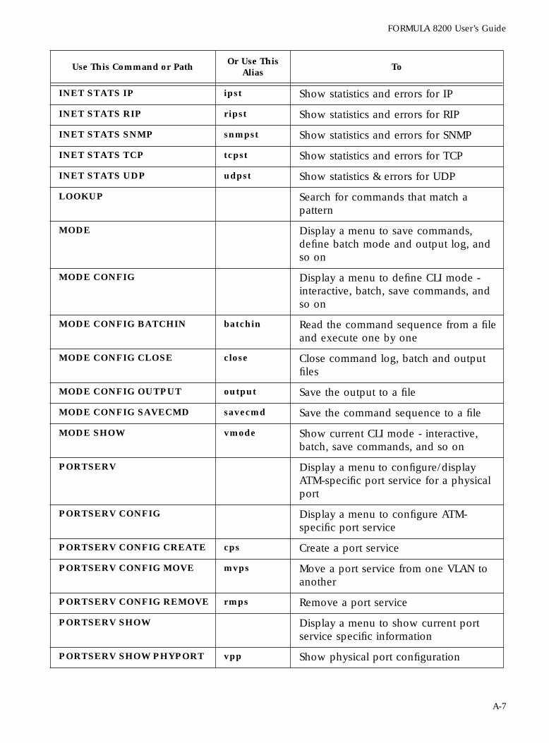
FORMULA 8200 User’s Guide
INET STATS IP ipst Show statistics and errors for IP
INET STATS RIP ripst Show statistics and errors for RIP
INET STATS SNMP snmpst Show statistics and errors for SNMP
INET STATS TCP tcpst Show statistics and errors for TCP
INET STATS UDP udpst Show statistics & errors for UDP
LOOKUP Search for commands that match a pattern
MODE Display a menu to save commands, define batch mode and output log, and so on
MODE CONFIG Display a menu to define CLI mode - interactive, batch, save commands, and so on
MODE CONFIG BATCHIN batchin Read the command sequence from a file and execute one by one
MODE CONFIG CLOSE close Close command log, batch and output files
MODE CONFIG OUTPUT output Save the output to a file
MODE CONFIG SAVECMD savecmd Save the command sequence to a file
MODE SHOW vmode Show current CLI mode - interactive, batch, save commands, and so on
PORTSERV Display a menu to configure/display ATM-specific port service for a physical port
PORTSERV CONFIG Display a menu to configure ATM-specific port service
PORTSERV CONFIG CREATE cps Create a port service
PORTSERV CONFIG MOVE mvps Move a port service from one VLAN to another
PORTSERV CONFIG REMOVE rmps Remove a port service
PORTSERV SHOW Display a menu to show current port service specific information
PORTSERV SHOW PHYPORT vpp Show physical port configuration
Use This Command or PathOr Use This
AliasTo
A-7
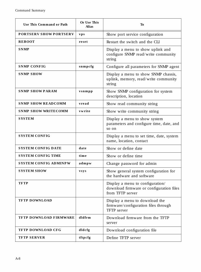
Command Summary
PORTSERV SHOW PORTSERV vps Show port service configuration
REBOOT reset Restart the switch and the CLI
SNMP Display a menu to show uplink and configure SNMP read/write community string
SNMP CONFIG snmpcfg Configure all parameters for SNMP agent
SNMP SHOW Display a menu to show SNMP chassis, uplink, memory, read/write community string
SNMP SHOW PARAM vsnmpp Show SNMP configuration for system description, location
SNMP SHOW READCOMM vread Show read community string
SNMP SHOW WRITECOMM vwrite Show write community string
SYSTEM Display a menu to show system parameters and configure time, date, and so on
SYSTEM CONFIG Display a menu to set time, date, system name, location, contact
SYSTEM CONFIG DATE date Show or define date
SYSTEM CONFIG TIME time Show or define time
SYSTEM CONFIG ADMINPW admpw Change password for admin
SYSTEM SHOW vsys Show general system configuration for the hardware and software
TFTP Display a menu to configuration/download firmware or configuration files from TFTP server
TFTP DOWNLOAD Display a menu to download the firmware/configuration files through TFTP server
TFTP DOWNLOAD FIRMWARE dldfrm Download firmware from the TFTP server
TFTP DOWNLOAD CFG dldcfg Download configuration file
TFTP SERVER tftpcfg Define TFTP server
Use This Command or PathOr Use This
AliasTo
A-8
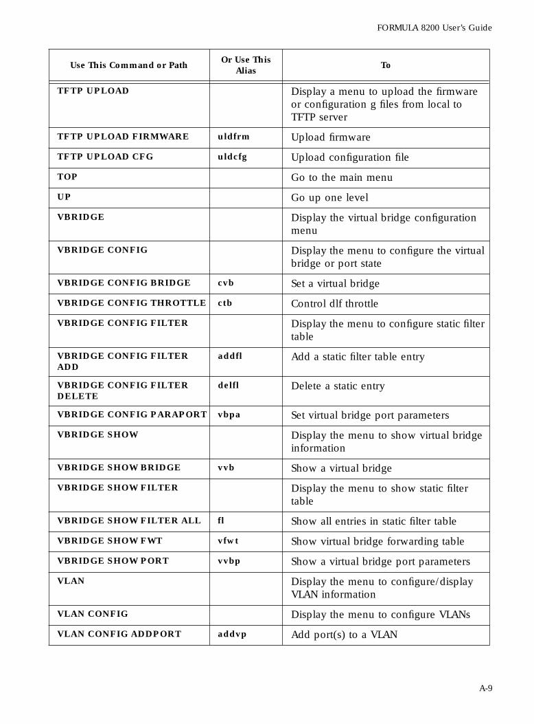
FORMULA 8200 User’s Guide
TFTP UPLOAD Display a menu to upload the firmware or configuration g files from local to TFTP server
TFTP UPLOAD FIRMWARE uldfrm Upload firmware
TFTP UPLOAD CFG uldcfg Upload configuration file
TOP Go to the main menu
UP Go up one level
VBRIDGE Display the virtual bridge configuration menu
VBRIDGE CONFIG Display the menu to configure the virtual bridge or port state
VBRIDGE CONFIG BRIDGE cvb Set a virtual bridge
VBRIDGE CONFIG THROTTLE ctb Control dlf throttle
VBRIDGE CONFIG FILTER Display the menu to configure static filter table
VBRIDGE CONFIG FILTER ADD
addfl Add a static filter table entry
VBRIDGE CONFIG FILTER DELETE
delfl Delete a static entry
VBRIDGE CONFIG PARAPORT vbpa Set virtual bridge port parameters
VBRIDGE SHOW Display the menu to show virtual bridge information
VBRIDGE SHOW BRIDGE vvb Show a virtual bridge
VBRIDGE SHOW FILTER Display the menu to show static filter table
VBRIDGE SHOW FILTER ALL fl Show all entries in static filter table
VBRIDGE SHOW FWT vfwt Show virtual bridge forwarding table
VBRIDGE SHOW PORT vvbp Show a virtual bridge port parameters
VLAN Display the menu to configure/display VLAN information
VLAN CONFIG Display the menu to configure VLANs
VLAN CONFIG ADDPORT addvp Add port(s) to a VLAN
Use This Command or PathOr Use This
AliasTo
A-9
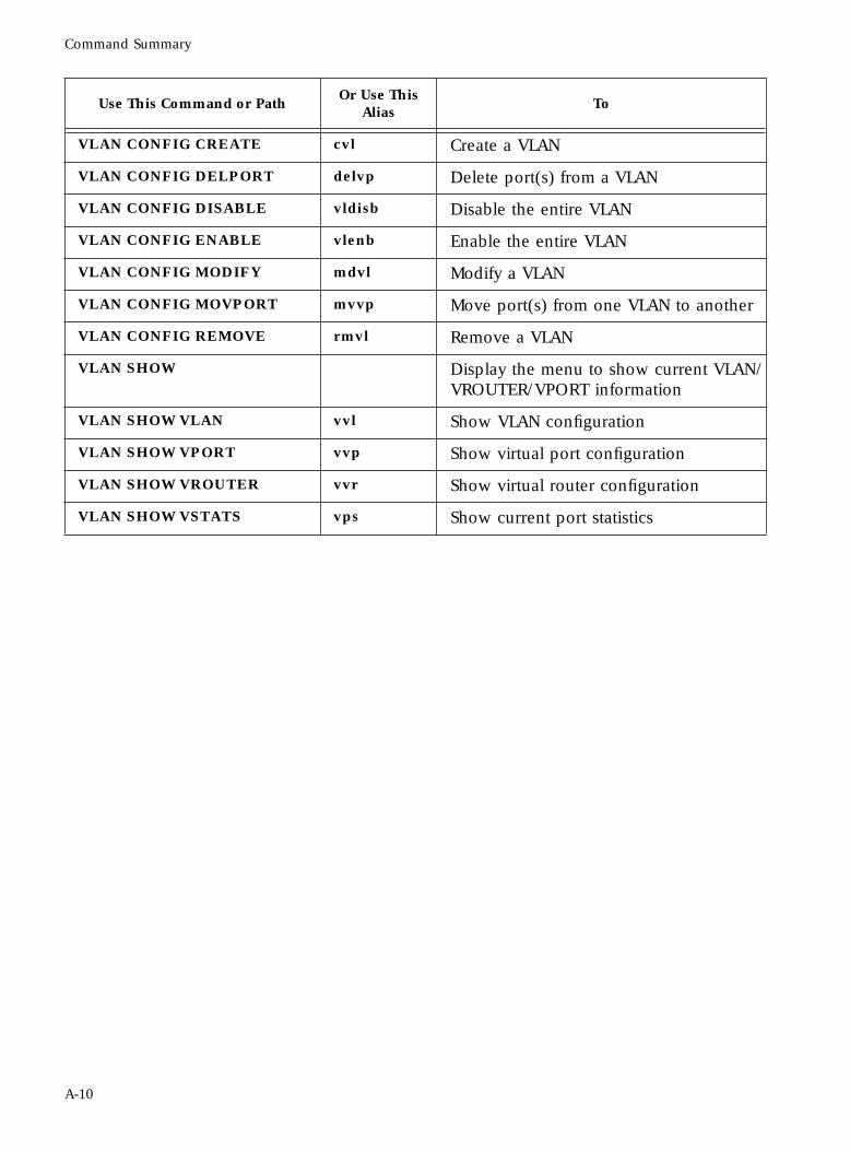
Command Summary
VLAN CONFIG CREATE cvl Create a VLAN
VLAN CONFIG DELPORT delvp Delete port(s) from a VLAN
VLAN CONFIG DISABLE vldisb Disable the entire VLAN
VLAN CONFIG ENABLE vlenb Enable the entire VLAN
VLAN CONFIG MODIFY mdvl Modify a VLAN
VLAN CONFIG MOVPORT mvvp Move port(s) from one VLAN to another
VLAN CONFIG REMOVE rmvl Remove a VLAN
VLAN SHOW Display the menu to show current VLAN/VROUTER/VPORT information
VLAN SHOW VLAN vvl Show VLAN configuration
VLAN SHOW VPORT vvp Show virtual port configuration
VLAN SHOW VROUTER vvr Show virtual router configuration
VLAN SHOW VSTATS vps Show current port statistics
Use This Command or PathOr Use This
AliasTo
A-10
Appendix B
RMON Configuration
This appendix provides the following information:
❑ A list of supported standard and proprietary MIBs
❑ The sequence followed by Castle Rock’s SNMPc® when compiling MIBs
❑ Sample procedures for enabling and disabling RMON objects
This appendix does not provide all the details on SNMP and assumes you are experienced in using SNMP commands to manage your network.
The FORMULA 8200 has an SNMP agent software that can provide information on the following RMON groups (RFC 1271):
❑ Statistics
❑ History
❑ Alarms
❑ Events
B-1
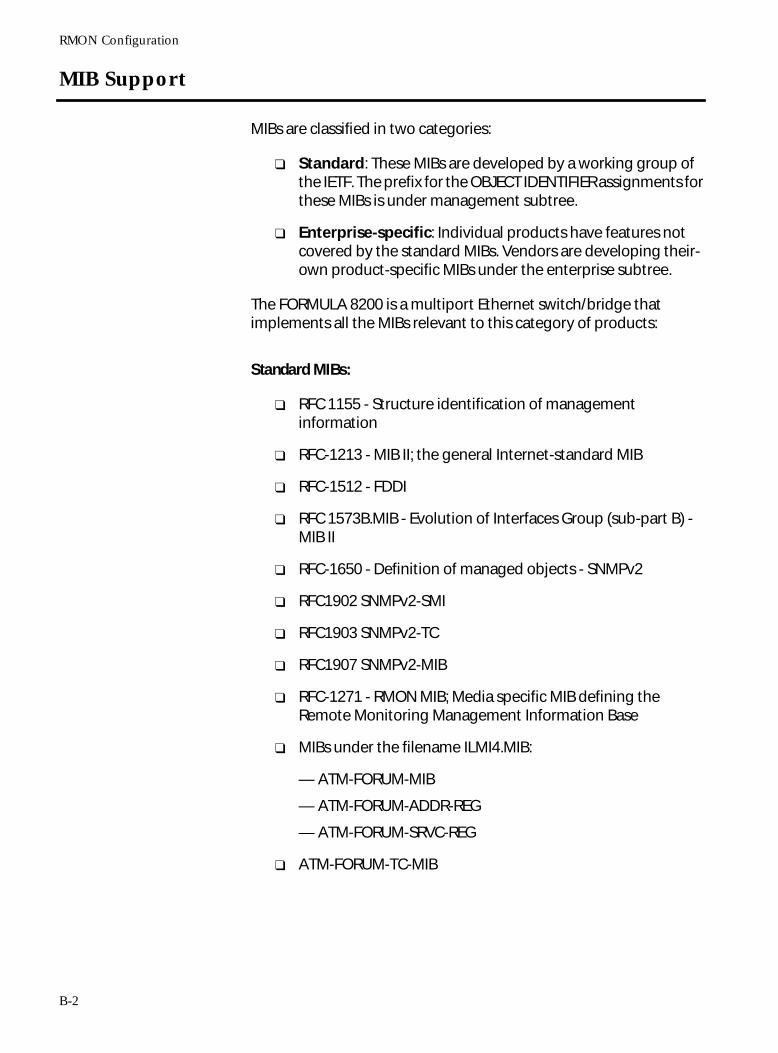
RMON Configuration
MIB Support
MIBs are classified in two categories:
❑ Standard: These MIBs are developed by a working group of the IETF. The prefix for the OBJECT IDENTIFIER assignments for these MIBs is under management subtree.
❑ Enterprise-specific: Individual products have features not covered by the standard MIBs. Vendors are developing their-own product-specific MIBs under the enterprise subtree.
The FORMULA 8200 is a multiport Ethernet switch/bridge that implements all the MIBs relevant to this category of products:
Standard MIBs:
❑ RFC 1155 - Structure identification of management information
❑ RFC-1213 - MIB II; the general Internet-standard MIB
❑ RFC-1512 - FDDI
❑ RFC 1573B.MIB - Evolution of Interfaces Group (sub-part B) - MIB II
❑ RFC-1650 - Definition of managed objects - SNMPv2
❑ RFC1902 SNMPv2-SMI
❑ RFC1903 SNMPv2-TC
❑ RFC1907 SNMPv2-MIB
❑ RFC-1271 - RMON MIB; Media specific MIB defining the Remote Monitoring Management Information Base
❑ MIBs under the filename ILMI4.MIB:
— ATM-FORUM-MIB
— ATM-FORUM-ADDR-REG
— ATM-FORUM-SRVC-REG
❑ ATM-FORUM-TC-MIB
B-2
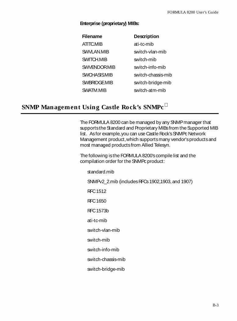
FORMULA 8200 User’s Guide
Enterprise (proprietary) MIBs:
SNMP Management Using Castle Rock’s SNMPc
The FORMULA 8200 can be managed by any SNMP manager that supports the Standard and Proprietary MIBs from the Supported MIB list. As for example, you can use Castle Rock’s SNMPc Network Management product, which supports many vendor's products and most managed products from Allied Telesyn.
The following is the FORMULA 8200’s compile list and the compilation order for the SNMPc product:
standard.mib
SNMPv2_2.mib (includes RFCs 1902,1903, and 1907)
RFC 1512
RFC 1650
RFC 1573b
ati-tc-mib
switch-vlan-mib
switch-mib
switch-info-mib
switch-chassis-mib
switch-bridge-mib
Filename Description
ATITC.MIB ati-tc-mib
SWVLAN.MIB switch-vlan-mib
SWITCH.MIB switch-mib
SWVENDOR.MIB switch-info-mib
SWCHASIS.MIB switch-chassis-mib
SWBRIDGE.MIB switch-bridge-mib
SWATM.MIB switch-atm-mib
B-3
RMON Configuration
ILMI4.MIB:
— atm-forum-mib
— atm-forum-addr-reg
— atm-forum-srvc-reg
— atm-forum-tc-mib
switch-atm-mib (included in ILMI4.MIB)
RFC 1271
The compile results in three warnings. These warnings will not affect the management of the FORMULA 8200.
The Product MIB files can be obtained from Allied Telesyn’s FTP server:
Address: ftp.alliedtelesyn.com [lowercase letters]Login: anonymous [lowercase letters]Password: your e-mail address [requested by the server at login]
To obtain Standard based RFC MIB files not available in your SNMP manager, contact the manufacturer of your SNMP manager for support. You can also find the standard RFCs on the WWW.INTERNIC.NET web site.
Go to the URL:
http://ds.internic.net/rfc/rfc<# of RFC>.txt
Substitute the number of the needed RFC for <# of RFC>
The ATM MIBs can be obtained from ATM Forum web site.
http://www.atmforum.com/atmforum/
The SNMPc compiler requires that the text content of the RFC be stripped before the RFC can be compiled by SNMPc. For future information on the SNMPc, see the SNMPc Network Management Reference Guide. Each SNMP compiler has it own requirements, so contact the manufacturer of you SNMP manager for support on that compiler’s requirements.
You can enable the RMON groups History, Alarm, and Event in SNMPc by using the RMON probe or using the Edit MIB var (F7) command. See the FORMULA 8200 User’s Guide on how to set up the SNMP parameters. See the SNMPc Network Management Reference Guide for information on managing RMON probes and MIB objects.
B-4
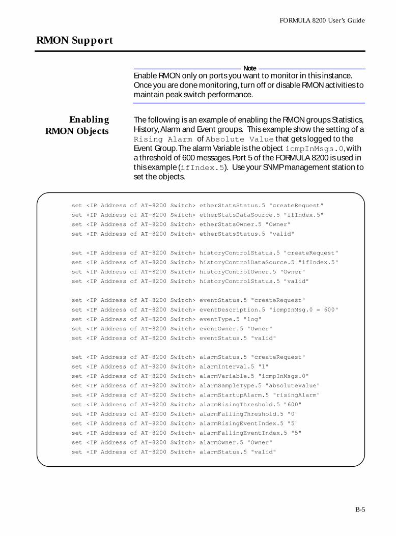
FORMULA 8200 User’s Guide
RMON Support
NoteEnable RMON only on ports you want to monitor in this instance. Once you are done monitoring, turn off or disable RMON activities to maintain peak switch performance.
EnablingRMON Objects
The following is an example of enabling the RMON groups Statistics, History, Alarm and Event groups. This example show the setting of a Rising Alarm of Absolute Value that gets logged to the Event Group. The alarm Variable is the object icmpInMsgs.0, with a threshold of 600 messages. Port 5 of the FORMULA 8200 is used in this example (ifIndex.5). Use your SNMP management station to set the objects.
set <IP Address of AT-8200 Switch> etherStatsStatus.5 "createRequest"
set <IP Address of AT-8200 Switch> etherStatsDataSource.5 "ifIndex.5"
set <IP Address of AT-8200 Switch> etherStatsOwner.5 "Owner"
set <IP Address of AT-8200 Switch> etherStatsStatus.5 "valid"
set <IP Address of AT-8200 Switch> historyControlStatus.5 "createRequest"
set <IP Address of AT-8200 Switch> historyControlDataSource.5 "ifIndex.5"
set <IP Address of AT-8200 Switch> historyControlOwner.5 "Owner"
set <IP Address of AT-8200 Switch> historyControlStatus.5 "valid"
set <IP Address of AT-8200 Switch> eventStatus.5 "createRequest"
set <IP Address of AT-8200 Switch> eventDescription.5 "icmpInMsg.0 = 600"
set <IP Address of AT-8200 Switch> eventType.5 "log"
set <IP Address of AT-8200 Switch> eventOwner.5 "Owner"
set <IP Address of AT-8200 Switch> eventStatus.5 "valid"
set <IP Address of AT-8200 Switch> alarmStatus.5 "createRequest"
set <IP Address of AT-8200 Switch> alarmInterval.5 "1"
set <IP Address of AT-8200 Switch> alarmVariable.5 "icmpInMsgs.0"
set <IP Address of AT-8200 Switch> alarmSampleType.5 "absoluteValue"
set <IP Address of AT-8200 Switch> alarmStartupAlarm.5 "risingAlarm"
set <IP Address of AT-8200 Switch> alarmRisingThreshold.5 "600"
set <IP Address of AT-8200 Switch> alarmFallingThreshold.5 "0"
set <IP Address of AT-8200 Switch> alarmRisingEventIndex.5 "5"
set <IP Address of AT-8200 Switch> alarmFallingEventIndex.5 "5"
set <IP Address of AT-8200 Switch> alarmOwner.5 "Owner"
set <IP Address of AT-8200 Switch> alarmStatus.5 "valid"
B-5
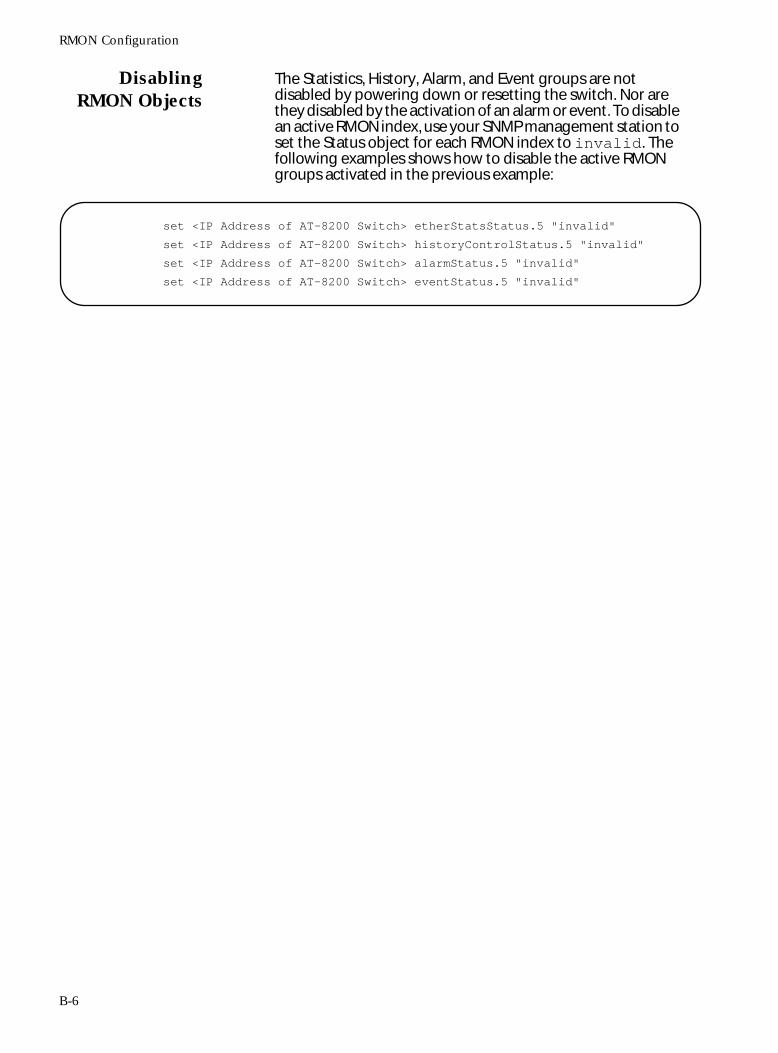
RMON Configuration
DisablingRMON Objects
The Statistics, History, Alarm, and Event groups are not disabled by powering down or resetting the switch. Nor are they disabled by the activation of an alarm or event. To disable an active RMON index, use your SNMP management station to set the Status object for each RMON index to invalid. The following examples shows how to disable the active RMON groups activated in the previous example:
set <IP Address of AT-8200 Switch> etherStatsStatus.5 "invalid"
set <IP Address of AT-8200 Switch> historyControlStatus.5 "invalid"
set <IP Address of AT-8200 Switch> alarmStatus.5 "invalid"
set <IP Address of AT-8200 Switch> eventStatus.5 "invalid"
B-6
Appendix C
Downloading Software at the [VxWorks] Prompt
This appendix describes the procedures to download software to your switch from the [VxWorks] prompt. To use these procedures, you must be logged in to another host on the network, for example, an SNMP management station.
CautionThe recommended procedure to upgrade software is via the FORMULA 8200’s command, TFTP. Follow the procedures in this appendix only if the switch’s command line interface (CLI) is not accessible for some reason, and if you are very familiar with VxWorks commands.
This appendix discusses the following topics:
❑ What you need prior to downloading the software
❑ Backing up your configurations
❑ Using FTP/TFTP or ZMODEM at the [VxWorks] prompt to upgrade software
❑ What to do in case of problems during the download
CautionThere is only enough space on the switch to store one version of software. Do not attempt to download multiple versions on the switch.
C-1
FORMULA 8200 User’s Guide
Firmware Upgrade Using FTP/TFTP
This section describes the procedures to use FTP/TFTP at the [VxWorks] prompt. If you can, use Port 1 for this procedure; however, you may use any port.
This procedure requires a workstation with both FTP and TFTP server capabilities.
Prior to the TFTP download process:
1. Your TFTP server must be running the TFTP daemon (UNIX) or a TFTP process (DOS/Windows). Without the daemon or the process, your download from your server will fail.
2. If you have Solaris , refer to Appendix B for the procedures to configure a TFTP server on that platform.
3. If you have DOS or Windows, you have several options:
❑ Castle Rock’s SNMPc includes a TFTP server. Refer to the documentation for server setup.
❑ Shareware TFTP servers are available for Windows 95 or
WindowsNT .
❑ For other TCP/IP stacks, check your software applications for details.
4. The IP address of the switch and the TFTP server must be on the same subnet.
5. You need the latest FORMULA 8200’s system software file from Allied Telesyn. The software is available from the World Wide Web or from Allied Telesyn’s anonymous FTP server. For questions, please phone the Allied Telesyn’s Technical Support. For information on how to contact the nearest Allied Telesyn location, refer to Appendix A.
6. Note the name of the FORMULA 8200 system software file that resides on your TFTP server. This is the software file you will download.
7. Make sure the software file on your server has read and write access. In UNIX, enter
chmod 777 <filename>
to give read and write access to the files. Then copy the software file to the appropriate directory on your TFTP server.
8. Verify the physical connection from your TFTP server to the FORMULA 8200.
C-2
FORMULA 8200 User’s Guide
Backing UpYour Current
Configurations
The upgrade may change some settings to new defaults, and this may or may not cause a problem.
To ensure your ability to restore your current switch configurations after the software upgrade, you need to back up the following configuration files to your TFTP server:
❑ SYSTEM.CUR contains the majority of the configuration files
❑ AGENT.CNF contains location, contact, and SNMP management information (backup optional)
1. Log in to the switch and PING the TFTP server to verify communications:
2. Assign an IP address to the TFTP server:
3. If you are using a UNIX TFTP server, the file must exist (for example, system.001) in the directory path indicated in the /etc/inetd.conf file. It must also have read, write, and execute permissions for everyone:
4. In your switch, backup the configuration files by using the TFTP/UPLOAD/CFG command. In this command, you need to specify the name of the file(s) you want to backup:
/>ping 192.48.127.124
192.48.127.124 is alive
/TFTP/SERVER
IP address of the tftp server () : 192.48.127.124 Save TFTP configuration to flash? (y/n) Y
Writing new TFTP configuration to flash ... Updating system/VLAN configuration....
cd /tftpboottouch system.001chmod 777 system.001.
C-3
FORMULA 8200 User’s Guide
5. Repeat the procedure to upload AGENT.CNF to a corresponding pre-existing file (for example, agent.001) in the server.
You are done backing up your files. You may proceed with the software upgrade.
Configuring forthe TFTP
DownloadProcess
The following steps provide the FORMULA 8200 with the IP address of your TFTP server:
1. Log in to the switch and enter:
/TFTP/SERVER
2. Enter the IP address of your TFTP server.
Enter Y in the Save the configuration to flash? (y/n) prompt to save the TFTP server configuration for later use.
3. Verify that you can PING the TFTP server from the FORMULA 8200.
You are now ready to download software to your FORMULA 8200 switch.
CautionThere is only enough space on the switch to store one version of software. Do not attempt to download multiple versions on the switch.
/>tftp/upload/cfgName of file on switch () : system.curName of file on tftp server () : system.001File “/flash/system.cur” on switch to be copied to server “192.48.127.124” as
“system.001”Are they correct? (y/n) ySave TFTP configuration to flash? (y/n) nLF = /flash/system.cur, RF = system.001, SRV = 192.48.127.124, op = put
/TFTP/UPLOAD>
/TFTP/SERVER
IP address of the tftp server () : 192.5.5.18 Save the configuration to flash? (y/n) Y
Writing new configuration to flash ... Updating system/VLAN configuration....
C-4
FORMULA 8200 User’s Guide
Downloadingthe Firmware
Using FTP/TFTP
This procedure requires a station with both FTP and TFTP server capabilities.
1. Reset the FORMULA 8200.
When the system starts, the following message appears:
2. Quickly press any key.
The VxWorks operating system prompt appears:
[VxWorks Boot]:
The flash needs to be formatted to accommodate the new version of the image software.
3. Enter F at the prompt to format the flash and confirm.
The system restarts and the following message appears:
4. Quickly press any key.
This returns you to the VxWorks operating system prompt:
[VxWorks Boot]:
5. Enter c to change the parameters for downloading the image software:
Press any key to stop auto-boot...
[VxWorks Boot]: F
WARNING: you are about to reformat the flash file system The system cannot boot after this. Are you sure (y/n):y
Formatting the flash ...done
Press any key to stop auto-boot...
[VxWorks Boot]: c
‘.’=clear field; ‘-’=go to previous field; ^D=quit
boot device:
C-5
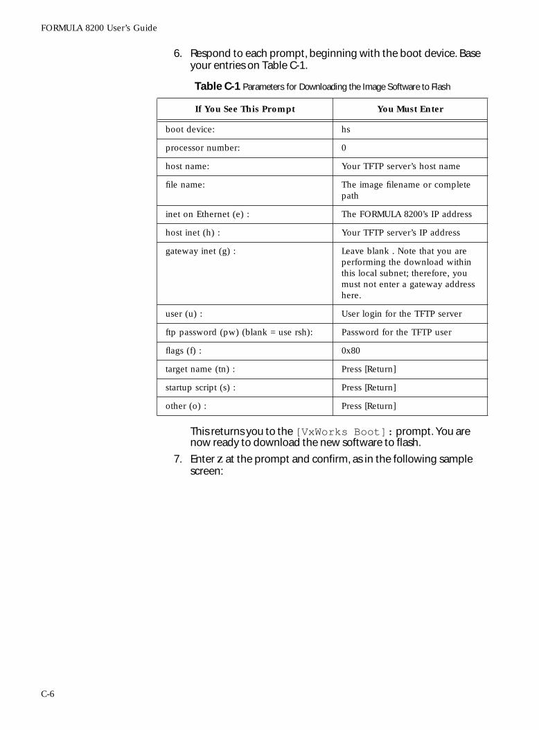
FORMULA 8200 User’s Guide
6. Respond to each prompt, beginning with the boot device. Base your entries on Table C-1.
This returns you to the [VxWorks Boot]: prompt. You are now ready to download the new software to flash.
7. Enter Z at the prompt and confirm, as in the following sample screen:
Table C-1 Parameters for Downloading the Image Software to Flash
If You See This Prompt You Must Enter
boot device: hs
processor number: 0
host name: Your TFTP server’s host name
file name: The image filename or complete path
inet on Ethernet (e) : The FORMULA 8200’s IP address
host inet (h) : Your TFTP server’s IP address
gateway inet (g) : Leave blank . Note that you are performing the download within this local subnet; therefore, you must not enter a gateway address here.
user (u) : User login for the TFTP server
ftp password (pw) (blank = use rsh): Password for the TFTP user
flags (f) : 0x80
target name (tn) : Press [Return]
startup script (s) : Press [Return]
other (o) : Press [Return]
C-6
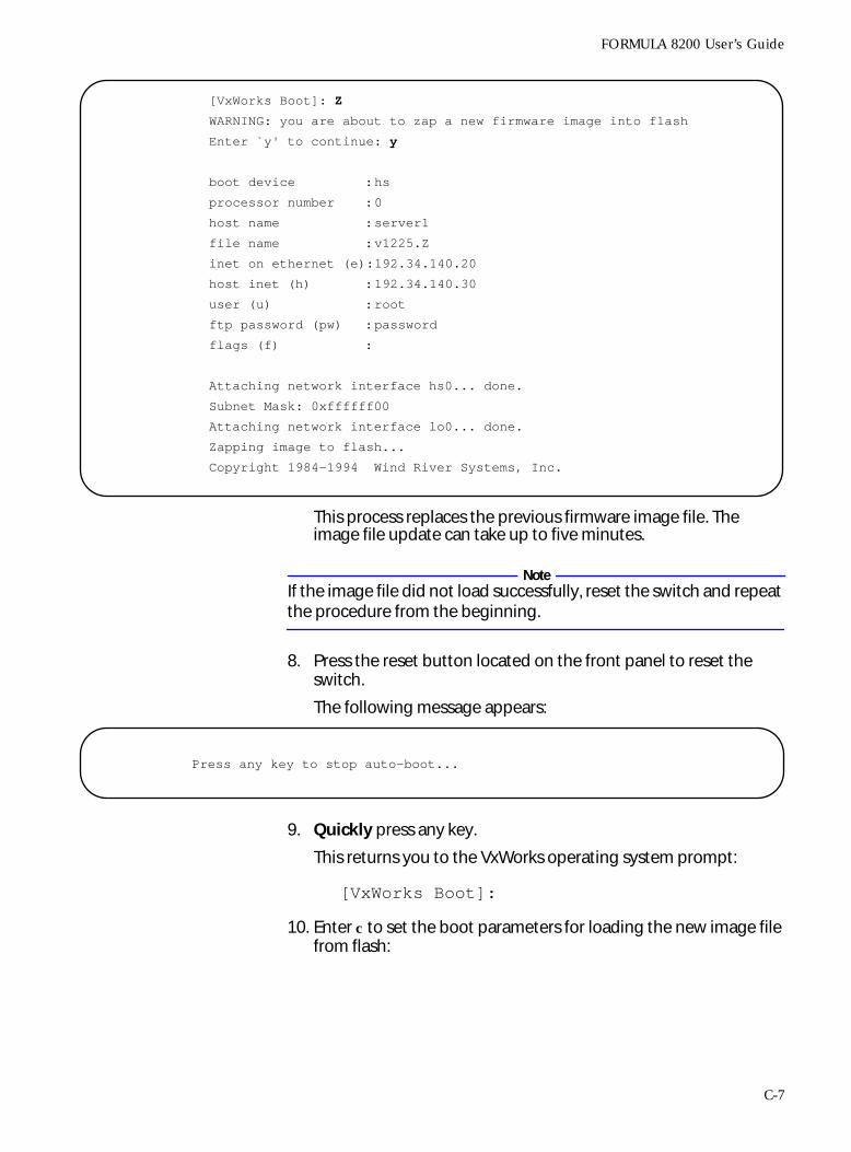
FORMULA 8200 User’s Guide
This process replaces the previous firmware image file. The image file update can take up to five minutes.
NoteIf the image file did not load successfully, reset the switch and repeat the procedure from the beginning.
8. Press the reset button located on the front panel to reset the switch.
The following message appears:
9. Quickly press any key.
This returns you to the VxWorks operating system prompt:
[VxWorks Boot]:
10. Enter c to set the boot parameters for loading the new image file from flash:
[VxWorks Boot]: Z
WARNING: you are about to zap a new firmware image into flash
Enter `y' to continue: y
boot device :hs
processor number :0
host name :server1
file name :v1225.Z
inet on ethernet (e):192.34.140.20
host inet (h) :192.34.140.30
user (u) :root
ftp password (pw) :password
flags (f) :
Attaching network interface hs0... done.
Subnet Mask: 0xffffff00
Attaching network interface lo0... done.
Zapping image to flash...
Copyright 1984-1994 Wind River Systems, Inc.
Press any key to stop auto-boot...
C-7
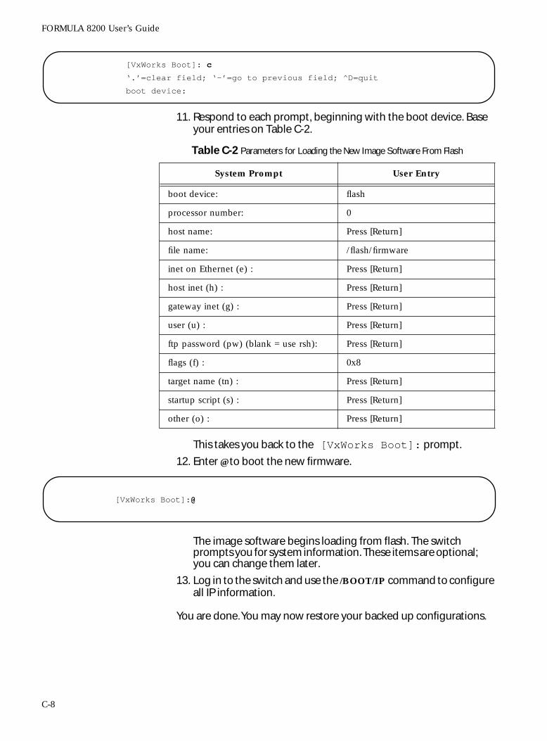
FORMULA 8200 User’s Guide
11. Respond to each prompt, beginning with the boot device. Base your entries on Table C-2.
This takes you back to the [VxWorks Boot]: prompt.
12. Enter @ to boot the new firmware.
The image software begins loading from flash. The switch prompts you for system information. These items are optional; you can change them later.
13. Log in to the switch and use the /BOOT/IP command to configure all IP information.
You are done. You may now restore your backed up configurations.
[VxWorks Boot]: c
‘.’=clear field; ‘-’=go to previous field; ^D=quit
boot device:
Table C-2 Parameters for Loading the New Image Software From Flash
System Prompt User Entry
boot device: flash
processor number: 0
host name: Press [Return]
file name: /flash/firmware
inet on Ethernet (e) : Press [Return]
host inet (h) : Press [Return]
gateway inet (g) : Press [Return]
user (u) : Press [Return]
ftp password (pw) (blank = use rsh): Press [Return]
flags (f) : 0x8
target name (tn) : Press [Return]
startup script (s) : Press [Return]
other (o) : Press [Return]
[VxWorks Boot]:@
C-8
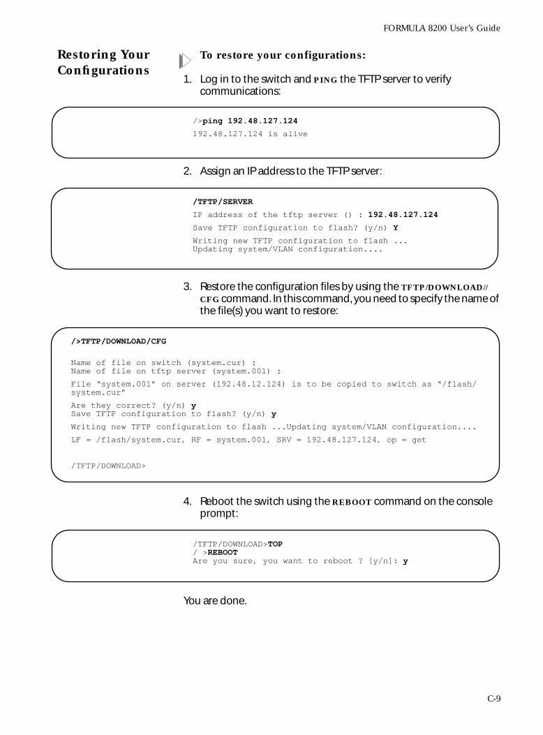
FORMULA 8200 User’s Guide
Restoring YourConfigurations
To restore your configurations:
1. Log in to the switch and PING the TFTP server to verify communications:
2. Assign an IP address to the TFTP server:
3. Restore the configuration files by using the TFTP/DOWNLOAD//CFG command. In this command, you need to specify the name of the file(s) you want to restore:
4. Reboot the switch using the REBOOT command on the console prompt:
You are done.
/>ping 192.48.127.124
192.48.127.124 is alive
/TFTP/SERVER
IP address of the tftp server () : 192.48.127.124 Save TFTP configuration to flash? (y/n) Y
Writing new TFTP configuration to flash ... Updating system/VLAN configuration....
/>TFTP/DOWNLOAD/CFG
Name of file on switch (system.cur) :Name of file on tftp server (system.001) :
File “system.001” on server (192.48.12.124) is to be copied to switch as “/flash/system.cur”
Are they correct? (y/n) ySave TFTP configuration to flash? (y/n) y
Writing new TFTP configuration to flash ...Updating system/VLAN configuration....
LF = /flash/system.cur, RF = system.001, SRV = 192.48.127.124, op = get
/TFTP/DOWNLOAD>
/TFTP/DOWNLOAD>TOP/ >REBOOTAre you sure, you want to reboot ? [y/n]: y
C-9
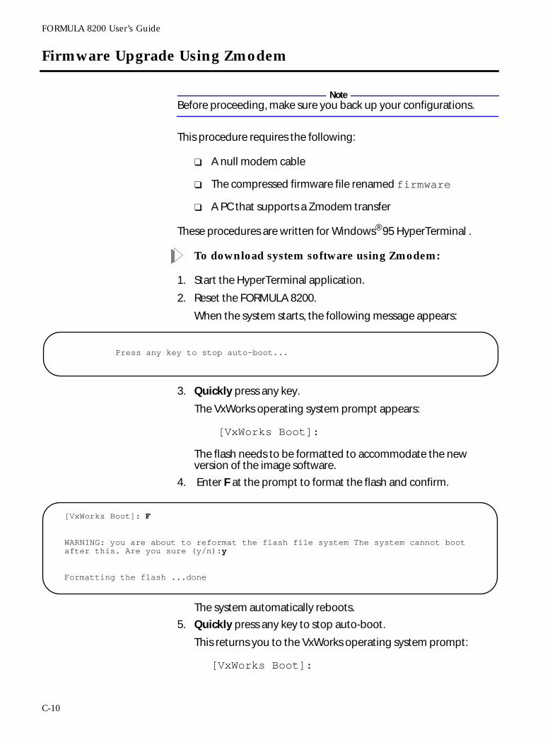
FORMULA 8200 User’s Guide
Firmware Upgrade Using Zmodem
NoteBefore proceeding, make sure you back up your configurations.
This procedure requires the following:
❑ A null modem cable
❑ The compressed firmware file renamed firmware
❑ A PC that supports a Zmodem transfer
These procedures are written for Windows® 95 HyperTerminal .
To download system software using Zmodem:
1. Start the HyperTerminal application.
2. Reset the FORMULA 8200.
When the system starts, the following message appears:
3. Quickly press any key.
The VxWorks operating system prompt appears:
[VxWorks Boot]:
The flash needs to be formatted to accommodate the new version of the image software.
4. Enter F at the prompt to format the flash and confirm.
The system automatically reboots.
5. Quickly press any key to stop auto-boot.
This returns you to the VxWorks operating system prompt:
[VxWorks Boot]:
Press any key to stop auto-boot...
[VxWorks Boot]: F
WARNING: you are about to reformat the flash file system The system cannot boot after this. Are you sure (y/n):y
Formatting the flash ...done
C-10
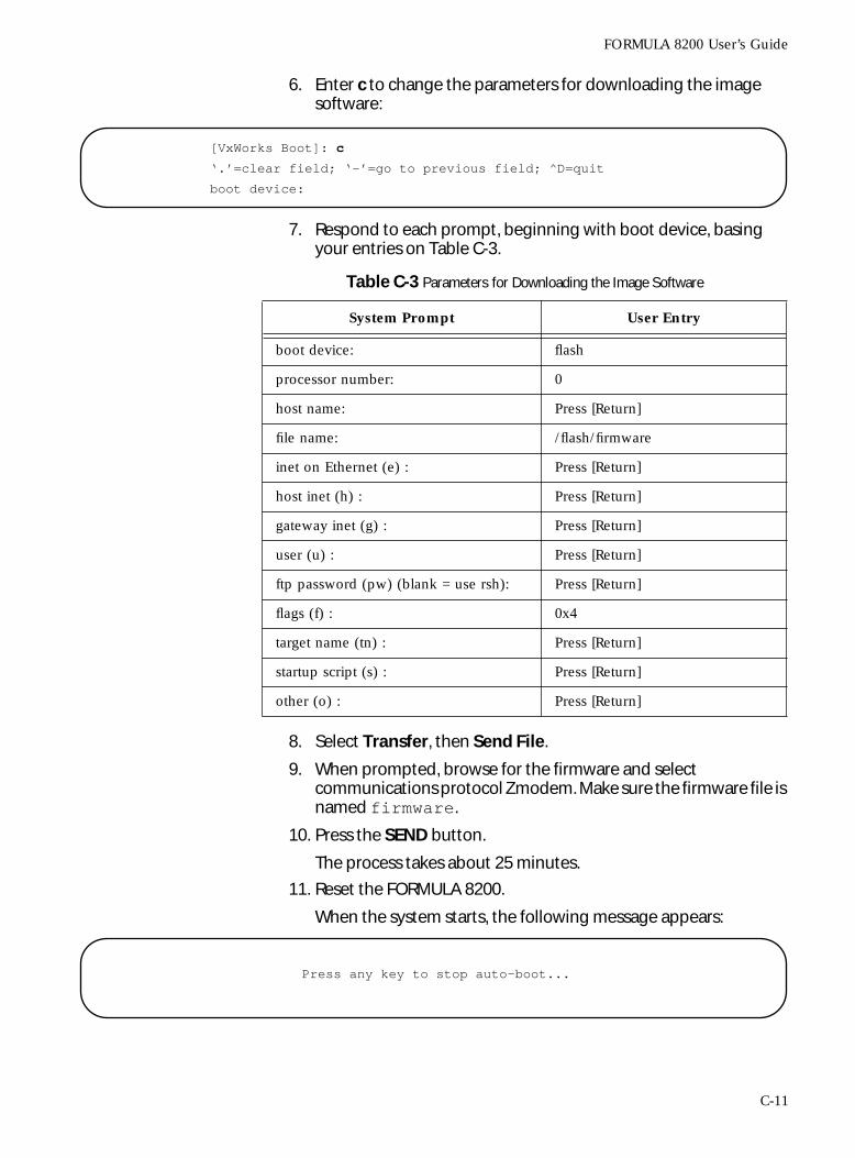
FORMULA 8200 User’s Guide
6. Enter c to change the parameters for downloading the image software:
7. Respond to each prompt, beginning with boot device, basing your entries on Table C-3.
8. Select Transfer, then Send File.
9. When prompted, browse for the firmware and select communications protocol Zmodem. Make sure the firmware file is named firmware.
10. Press the SEND button.
The process takes about 25 minutes.
11. Reset the FORMULA 8200.
When the system starts, the following message appears:
[VxWorks Boot]: c
‘.’=clear field; ‘-’=go to previous field; ^D=quit
boot device:
Table C-3 Parameters for Downloading the Image Software
System Prompt User Entry
boot device: flash
processor number: 0
host name: Press [Return]
file name: /flash/firmware
inet on Ethernet (e) : Press [Return]
host inet (h) : Press [Return]
gateway inet (g) : Press [Return]
user (u) : Press [Return]
ftp password (pw) (blank = use rsh): Press [Return]
flags (f) : 0x4
target name (tn) : Press [Return]
startup script (s) : Press [Return]
other (o) : Press [Return]
Press any key to stop auto-boot...
C-11
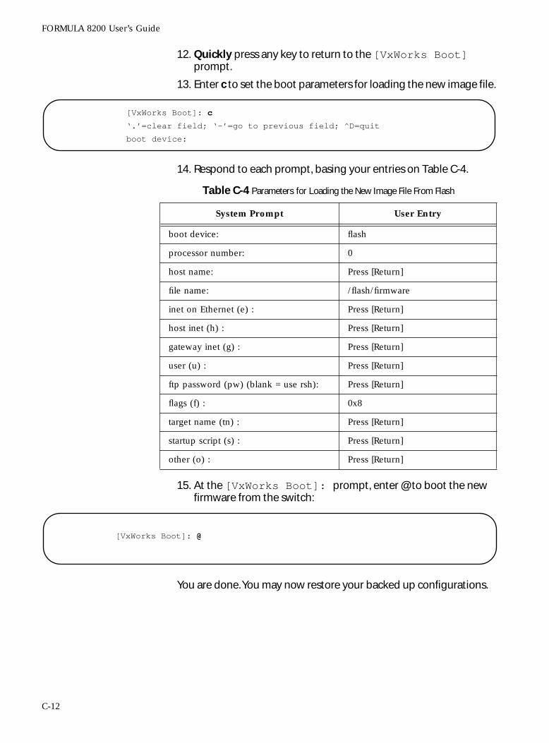
FORMULA 8200 User’s Guide
12. Quickly press any key to return to the [VxWorks Boot] prompt.
13. Enter c to set the boot parameters for loading the new image file.
14. Respond to each prompt, basing your entries on Table C-4.
15. At the [VxWorks Boot]: prompt, enter @ to boot the new firmware from the switch:
You are done. You may now restore your backed up configurations.
[VxWorks Boot]: c
‘.’=clear field; ‘-’=go to previous field; ^D=quit
boot device:
Table C-4 Parameters for Loading the New Image File From Flash
System Prompt User Entry
boot device: flash
processor number: 0
host name: Press [Return]
file name: /flash/firmware
inet on Ethernet (e) : Press [Return]
host inet (h) : Press [Return]
gateway inet (g) : Press [Return]
user (u) : Press [Return]
ftp password (pw) (blank = use rsh): Press [Return]
flags (f) : 0x8
target name (tn) : Press [Return]
startup script (s) : Press [Return]
other (o) : Press [Return]
[VxWorks Boot]: @
C-12
FORMULA 8200 User’s Guide
In Case of Problems With the Software Upgrade
Interrupting a software download (for example, rebooting the switch or disconnecting the power cord) creates files of 0 bytes. Attempts to download again will not succeed because the download process cannot write over these files.
If you encounter these problems:
1. Log in to the switch.
2. Manually delete the firmware file by entering:
/FILE/DELETE firmware
3. Download the firmware again.
C-13

Index
Symbols<> angle brackets, use of, 2-8[] square brackets, use of, 2-8
Aaliases, commands, 5-2—5-4, 5-7
Bbacking up, configurations, 4-20—4-21blocking state, 3-7BPDUs, 3-7bridge forwarding table, see forwarding table
Ccommand line interface (CLI)
accessing, 2-6command tree, 5-2—5-4current mode, viewing and configuring,
5-31—5-32description of, 2-8main menu, 5-1navigating, 2-10, 5-40, 5-41
command mode, 5-6commands
formats, 2-9list of, A-1—A-10listing all, 5-8, 5-30
configurationdefault settings, 3-1IP parameters, 2-11saving to flash, 5-11
configurationsports on the switch, 1-2
consoleconnecting, 2-2parameters, showing, 2-2, 5-13securing, 5-13terminal settings, 2-2
conventions, used in guide, x
Ddata loops, 3-6default configuration, 3-1downloading software
FTP/TFTP, C-2—C-9TFTP command, 4-22—4-23, 5-39—5-40Zmodem, C-10—C-12
Eedit mode, 5-6error log
clearing, 5-15description, 5-14viewing information from, 5-15—5-16
Ffeatures, FORMULA 8200, 1-1—1-2files
commands, description, 5-25copying, 5-26listing, 5-26
firmware, upgrading, 4-19—4-24forwarding state, 3-7forwarding table, 4-18, 5-50FTP server, accessing, xiii, B-4
Index-1
Index
Hhelp, online, 4-2
Iicons, used in guide, xIP address, assigning, 5-11IP address, TFTP server, configuring, 5-40IP parameters, configuration, 5-27—5-28
LLAN concepts, list of, viiilearning state, 3-7LEDs
description of, 2-4system and port, examples, 2-4
listening state, 3-7logging in
with password, 2-6without password, 2-7
loops, data, without spanning tree, 3-6
MMAC address table
static entry, creating, 3-12storage capacity, 5-24
menu tree, 5-2—5-4mirroring, port, 4-9—4-11
Ppassword, logging in, 2-6—2-7ping command, 5-28port
clearing statistics 5-24configuring, 4-6enabling Ethernet settings, 5-18mirroring, 4-9—4-11setting receive mirroring, 5-19setting snoop port, 5-19statistics, configuring, 4-7, 5-19statistics, viewing, 5-21—5-23viewing settings, 4-5, 5-21viewing spanning tree parameters, 4-17
port configurations, 1-2power-on self-test (POST), 2-3—2-4problems with, software upgrades, 4-25
Index-2
Rreboot, 2-15, 5-33related documents, xireset, 2-15restoring, backed up configurations, 4-24RMON
disabling MIB objects, B-6enabling MIB objects, B-5groups supported, B-1MIBs supported, list of, B-2—B-3
routing information protocol (RIP)changing, modes, 4-27removing default routes, 4-29viewing, 4-26, 5-29
Ssimple network management protocol (SNMP)
parameters, configuring, 4-30, 5-36parameters, viewing, 4-31, 5-37
SNMPc, managing with, B-3—B-4snoop port, 4-9, 4-11, 5-19software upgrades, problems with, 4-25spanning tree
configuring, 3-11—3-13configuring, for VLAN, 5-44—5-45description of, 3-6—3-7disabling, for port, 5-46—5-47disabling, for VLAN, 5-44optimization of, 3-12viewing parameters, for port, 4-17viewing parameters, for switch, 4-16,
5-48—5-50static entry, MAC address table, 3-12static routes, 4-28statistics
clearing counters, port, 4-9enabling, for port, 4-7viewing, TCP, 5-29
switch configuration, see system configurationsyntax, see commands, syntaxsystem configuration, 5-38system configuration, viewing 4-2—4-3
FORMULA 8200 User’s Guide
TTCP statistics, viewing, 5-29Telnet, to access switch, 2-14terminal, see console
Vviewing
firmware information, 2-13port settings 4-5SNMP parameters, 5-37system configuration, 4-2—4-3virtual bridge parameters, 3-13
virtual bridgeconfiguring 5-42configuring, 3-11—3-13, 5-44—5-47description, 3-5viewing information, 4-16viewing, 5-42—5-43, 5-48—5-50
virtual LANs (VLANs)commands, 5-51communications between, 3-3configuring, 3-8—3-10default VLAN, FORMULA 8200, 3-3deleting ports from, 5-52description of, 3-2—3-7multiple VLANs, example, 3-3removing, 5-52saving to flash, configuration, 5-11viewing information, 4-12, 5-52virtual routing, 3-5
virtual portviewing information, 4-14viewing statistics, 4-15
virtual routerdescription, 3-5viewing information, 4-13
virtual routing, 3-5VT-100 terminal, connecting, 2-2
Index-3


![Multi-Port Fast Ethernet Print Server1].pdf · Multi-Port Fast Ethernet Print Server FPS-3300 User’s Manual 1](https://img.pdfslide.us/doc/110x75/5f8848bdc824844a0b17dfd3/multi-port-fast-ethernet-print-1pdf-multi-port-fast-ethernet-print-server-fps-3300.jpg)